US9017389B2 - Methods for facet joint treatment - Google Patents
Methods for facet joint treatmentDownload PDFInfo
- Publication number
- US9017389B2 US9017389B2US13/793,977US201313793977AUS9017389B2US 9017389 B2US9017389 B2US 9017389B2US 201313793977 AUS201313793977 AUS 201313793977AUS 9017389 B2US9017389 B2US 9017389B2
- Authority
- US
- United States
- Prior art keywords
- resurfacing
- superior
- inferior
- facet
- facet joint
- Prior art date
- Legal status (The legal status is an assumption and is not a legal conclusion. Google has not performed a legal analysis and makes no representation as to the accuracy of the status listed.)
- Active, expires
Links
Images


Classifications
- A—HUMAN NECESSITIES
- A61—MEDICAL OR VETERINARY SCIENCE; HYGIENE
- A61F—FILTERS IMPLANTABLE INTO BLOOD VESSELS; PROSTHESES; DEVICES PROVIDING PATENCY TO, OR PREVENTING COLLAPSING OF, TUBULAR STRUCTURES OF THE BODY, e.g. STENTS; ORTHOPAEDIC, NURSING OR CONTRACEPTIVE DEVICES; FOMENTATION; TREATMENT OR PROTECTION OF EYES OR EARS; BANDAGES, DRESSINGS OR ABSORBENT PADS; FIRST-AID KITS
- A61F2/00—Filters implantable into blood vessels; Prostheses, i.e. artificial substitutes or replacements for parts of the body; Appliances for connecting them with the body; Devices providing patency to, or preventing collapsing of, tubular structures of the body, e.g. stents
- A61F2/02—Prostheses implantable into the body
- A61F2/30—Joints
- A61F2/44—Joints for the spine, e.g. vertebrae, spinal discs
- A61F2/4405—Joints for the spine, e.g. vertebrae, spinal discs for apophyseal or facet joints, i.e. between adjacent spinous or transverse processes
- A—HUMAN NECESSITIES
- A61—MEDICAL OR VETERINARY SCIENCE; HYGIENE
- A61F—FILTERS IMPLANTABLE INTO BLOOD VESSELS; PROSTHESES; DEVICES PROVIDING PATENCY TO, OR PREVENTING COLLAPSING OF, TUBULAR STRUCTURES OF THE BODY, e.g. STENTS; ORTHOPAEDIC, NURSING OR CONTRACEPTIVE DEVICES; FOMENTATION; TREATMENT OR PROTECTION OF EYES OR EARS; BANDAGES, DRESSINGS OR ABSORBENT PADS; FIRST-AID KITS
- A61F2/00—Filters implantable into blood vessels; Prostheses, i.e. artificial substitutes or replacements for parts of the body; Appliances for connecting them with the body; Devices providing patency to, or preventing collapsing of, tubular structures of the body, e.g. stents
- A61F2/02—Prostheses implantable into the body
- A61F2/30—Joints
- A61F2/46—Special tools for implanting artificial joints
- A61F2/4603—Special tools for implanting artificial joints for insertion or extraction of endoprosthetic joints or of accessories thereof
- A61F2/4611—Special tools for implanting artificial joints for insertion or extraction of endoprosthetic joints or of accessories thereof of spinal prostheses
- A—HUMAN NECESSITIES
- A61—MEDICAL OR VETERINARY SCIENCE; HYGIENE
- A61F—FILTERS IMPLANTABLE INTO BLOOD VESSELS; PROSTHESES; DEVICES PROVIDING PATENCY TO, OR PREVENTING COLLAPSING OF, TUBULAR STRUCTURES OF THE BODY, e.g. STENTS; ORTHOPAEDIC, NURSING OR CONTRACEPTIVE DEVICES; FOMENTATION; TREATMENT OR PROTECTION OF EYES OR EARS; BANDAGES, DRESSINGS OR ABSORBENT PADS; FIRST-AID KITS
- A61F2/00—Filters implantable into blood vessels; Prostheses, i.e. artificial substitutes or replacements for parts of the body; Appliances for connecting them with the body; Devices providing patency to, or preventing collapsing of, tubular structures of the body, e.g. stents
- A61F2/02—Prostheses implantable into the body
- A61F2/30—Joints
- A61F2002/30001—Additional features of subject-matter classified in A61F2/28, A61F2/30 and subgroups thereof
- A61F2002/30003—Material related properties of the prosthesis or of a coating on the prosthesis
- A61F2002/3006—Properties of materials and coating materials
- A61F2002/3008—Properties of materials and coating materials radio-opaque, e.g. radio-opaque markers
- A—HUMAN NECESSITIES
- A61—MEDICAL OR VETERINARY SCIENCE; HYGIENE
- A61F—FILTERS IMPLANTABLE INTO BLOOD VESSELS; PROSTHESES; DEVICES PROVIDING PATENCY TO, OR PREVENTING COLLAPSING OF, TUBULAR STRUCTURES OF THE BODY, e.g. STENTS; ORTHOPAEDIC, NURSING OR CONTRACEPTIVE DEVICES; FOMENTATION; TREATMENT OR PROTECTION OF EYES OR EARS; BANDAGES, DRESSINGS OR ABSORBENT PADS; FIRST-AID KITS
- A61F2/00—Filters implantable into blood vessels; Prostheses, i.e. artificial substitutes or replacements for parts of the body; Appliances for connecting them with the body; Devices providing patency to, or preventing collapsing of, tubular structures of the body, e.g. stents
- A61F2/02—Prostheses implantable into the body
- A61F2/30—Joints
- A61F2002/30001—Additional features of subject-matter classified in A61F2/28, A61F2/30 and subgroups thereof
- A61F2002/30108—Shapes
- A61F2002/30199—Three-dimensional shapes
- A61F2002/30299—Three-dimensional shapes umbrella-shaped or mushroom-shaped
- A—HUMAN NECESSITIES
- A61—MEDICAL OR VETERINARY SCIENCE; HYGIENE
- A61F—FILTERS IMPLANTABLE INTO BLOOD VESSELS; PROSTHESES; DEVICES PROVIDING PATENCY TO, OR PREVENTING COLLAPSING OF, TUBULAR STRUCTURES OF THE BODY, e.g. STENTS; ORTHOPAEDIC, NURSING OR CONTRACEPTIVE DEVICES; FOMENTATION; TREATMENT OR PROTECTION OF EYES OR EARS; BANDAGES, DRESSINGS OR ABSORBENT PADS; FIRST-AID KITS
- A61F2/00—Filters implantable into blood vessels; Prostheses, i.e. artificial substitutes or replacements for parts of the body; Appliances for connecting them with the body; Devices providing patency to, or preventing collapsing of, tubular structures of the body, e.g. stents
- A61F2/02—Prostheses implantable into the body
- A61F2/30—Joints
- A61F2002/30001—Additional features of subject-matter classified in A61F2/28, A61F2/30 and subgroups thereof
- A61F2002/30316—The prosthesis having different structural features at different locations within the same prosthesis; Connections between prosthetic parts; Special structural features of bone or joint prostheses not otherwise provided for
- A61F2002/30535—Special structural features of bone or joint prostheses not otherwise provided for
- A61F2002/30576—Special structural features of bone or joint prostheses not otherwise provided for with extending fixation tabs
- A61F2002/30578—Special structural features of bone or joint prostheses not otherwise provided for with extending fixation tabs having apertures, e.g. for receiving fixation screws
- A—HUMAN NECESSITIES
- A61—MEDICAL OR VETERINARY SCIENCE; HYGIENE
- A61F—FILTERS IMPLANTABLE INTO BLOOD VESSELS; PROSTHESES; DEVICES PROVIDING PATENCY TO, OR PREVENTING COLLAPSING OF, TUBULAR STRUCTURES OF THE BODY, e.g. STENTS; ORTHOPAEDIC, NURSING OR CONTRACEPTIVE DEVICES; FOMENTATION; TREATMENT OR PROTECTION OF EYES OR EARS; BANDAGES, DRESSINGS OR ABSORBENT PADS; FIRST-AID KITS
- A61F2/00—Filters implantable into blood vessels; Prostheses, i.e. artificial substitutes or replacements for parts of the body; Appliances for connecting them with the body; Devices providing patency to, or preventing collapsing of, tubular structures of the body, e.g. stents
- A61F2/02—Prostheses implantable into the body
- A61F2/30—Joints
- A61F2/30767—Special external or bone-contacting surface, e.g. coating for improving bone ingrowth
- A61F2/30771—Special external or bone-contacting surface, e.g. coating for improving bone ingrowth applied in original prostheses, e.g. holes or grooves
- A61F2002/30841—Sharp anchoring protrusions for impaction into the bone, e.g. sharp pins, spikes
- A61F2002/30843—Pyramidally-shaped
- A—HUMAN NECESSITIES
- A61—MEDICAL OR VETERINARY SCIENCE; HYGIENE
- A61F—FILTERS IMPLANTABLE INTO BLOOD VESSELS; PROSTHESES; DEVICES PROVIDING PATENCY TO, OR PREVENTING COLLAPSING OF, TUBULAR STRUCTURES OF THE BODY, e.g. STENTS; ORTHOPAEDIC, NURSING OR CONTRACEPTIVE DEVICES; FOMENTATION; TREATMENT OR PROTECTION OF EYES OR EARS; BANDAGES, DRESSINGS OR ABSORBENT PADS; FIRST-AID KITS
- A61F2/00—Filters implantable into blood vessels; Prostheses, i.e. artificial substitutes or replacements for parts of the body; Appliances for connecting them with the body; Devices providing patency to, or preventing collapsing of, tubular structures of the body, e.g. stents
- A61F2/02—Prostheses implantable into the body
- A61F2/30—Joints
- A61F2/30767—Special external or bone-contacting surface, e.g. coating for improving bone ingrowth
- A61F2/30771—Special external or bone-contacting surface, e.g. coating for improving bone ingrowth applied in original prostheses, e.g. holes or grooves
- A61F2002/30841—Sharp anchoring protrusions for impaction into the bone, e.g. sharp pins, spikes
- A61F2002/30845—Sharp anchoring protrusions for impaction into the bone, e.g. sharp pins, spikes with cutting edges
- A—HUMAN NECESSITIES
- A61—MEDICAL OR VETERINARY SCIENCE; HYGIENE
- A61F—FILTERS IMPLANTABLE INTO BLOOD VESSELS; PROSTHESES; DEVICES PROVIDING PATENCY TO, OR PREVENTING COLLAPSING OF, TUBULAR STRUCTURES OF THE BODY, e.g. STENTS; ORTHOPAEDIC, NURSING OR CONTRACEPTIVE DEVICES; FOMENTATION; TREATMENT OR PROTECTION OF EYES OR EARS; BANDAGES, DRESSINGS OR ABSORBENT PADS; FIRST-AID KITS
- A61F2/00—Filters implantable into blood vessels; Prostheses, i.e. artificial substitutes or replacements for parts of the body; Appliances for connecting them with the body; Devices providing patency to, or preventing collapsing of, tubular structures of the body, e.g. stents
- A61F2/02—Prostheses implantable into the body
- A61F2/30—Joints
- A61F2/30767—Special external or bone-contacting surface, e.g. coating for improving bone ingrowth
- A61F2/30771—Special external or bone-contacting surface, e.g. coating for improving bone ingrowth applied in original prostheses, e.g. holes or grooves
- A61F2002/3085—Special external or bone-contacting surface, e.g. coating for improving bone ingrowth applied in original prostheses, e.g. holes or grooves with a threaded, e.g. self-tapping, bone-engaging surface, e.g. external surface
- A—HUMAN NECESSITIES
- A61—MEDICAL OR VETERINARY SCIENCE; HYGIENE
- A61F—FILTERS IMPLANTABLE INTO BLOOD VESSELS; PROSTHESES; DEVICES PROVIDING PATENCY TO, OR PREVENTING COLLAPSING OF, TUBULAR STRUCTURES OF THE BODY, e.g. STENTS; ORTHOPAEDIC, NURSING OR CONTRACEPTIVE DEVICES; FOMENTATION; TREATMENT OR PROTECTION OF EYES OR EARS; BANDAGES, DRESSINGS OR ABSORBENT PADS; FIRST-AID KITS
- A61F2/00—Filters implantable into blood vessels; Prostheses, i.e. artificial substitutes or replacements for parts of the body; Appliances for connecting them with the body; Devices providing patency to, or preventing collapsing of, tubular structures of the body, e.g. stents
- A61F2/02—Prostheses implantable into the body
- A61F2/30—Joints
- A61F2/30767—Special external or bone-contacting surface, e.g. coating for improving bone ingrowth
- A61F2/30771—Special external or bone-contacting surface, e.g. coating for improving bone ingrowth applied in original prostheses, e.g. holes or grooves
- A61F2002/30878—Special external or bone-contacting surface, e.g. coating for improving bone ingrowth applied in original prostheses, e.g. holes or grooves with non-sharp protrusions, for instance contacting the bone for anchoring, e.g. keels, pegs, pins, posts, shanks, stems, struts
- A—HUMAN NECESSITIES
- A61—MEDICAL OR VETERINARY SCIENCE; HYGIENE
- A61F—FILTERS IMPLANTABLE INTO BLOOD VESSELS; PROSTHESES; DEVICES PROVIDING PATENCY TO, OR PREVENTING COLLAPSING OF, TUBULAR STRUCTURES OF THE BODY, e.g. STENTS; ORTHOPAEDIC, NURSING OR CONTRACEPTIVE DEVICES; FOMENTATION; TREATMENT OR PROTECTION OF EYES OR EARS; BANDAGES, DRESSINGS OR ABSORBENT PADS; FIRST-AID KITS
- A61F2/00—Filters implantable into blood vessels; Prostheses, i.e. artificial substitutes or replacements for parts of the body; Appliances for connecting them with the body; Devices providing patency to, or preventing collapsing of, tubular structures of the body, e.g. stents
- A61F2/02—Prostheses implantable into the body
- A61F2/30—Joints
- A61F2/30767—Special external or bone-contacting surface, e.g. coating for improving bone ingrowth
- A61F2/30771—Special external or bone-contacting surface, e.g. coating for improving bone ingrowth applied in original prostheses, e.g. holes or grooves
- A61F2002/30904—Special external or bone-contacting surface, e.g. coating for improving bone ingrowth applied in original prostheses, e.g. holes or grooves serrated profile, i.e. saw-toothed
- A—HUMAN NECESSITIES
- A61—MEDICAL OR VETERINARY SCIENCE; HYGIENE
- A61F—FILTERS IMPLANTABLE INTO BLOOD VESSELS; PROSTHESES; DEVICES PROVIDING PATENCY TO, OR PREVENTING COLLAPSING OF, TUBULAR STRUCTURES OF THE BODY, e.g. STENTS; ORTHOPAEDIC, NURSING OR CONTRACEPTIVE DEVICES; FOMENTATION; TREATMENT OR PROTECTION OF EYES OR EARS; BANDAGES, DRESSINGS OR ABSORBENT PADS; FIRST-AID KITS
- A61F2250/00—Special features of prostheses classified in groups A61F2/00 - A61F2/26 or A61F2/82 or A61F9/00 or A61F11/00 or subgroups thereof
- A61F2250/0058—Additional features; Implant or prostheses properties not otherwise provided for
- A61F2250/0096—Markers and sensors for detecting a position or changes of a position of an implant, e.g. RF sensors, ultrasound markers
- A61F2250/0098—Markers and sensors for detecting a position or changes of a position of an implant, e.g. RF sensors, ultrasound markers radio-opaque, e.g. radio-opaque markers
Definitions
- the present disclosurerelates to systems and methods for treating patients experiencing zygapophyseal (facet) joint-related pain. More particularly, it relates to implantable systems, and corresponding insertion methods and procedures that effectuate resurfacing of the facet joint anatomy on a minimally-invasive basis to minimize pain and reestablish or maintain normal or near-normal facet joint stabilization and motion.
- articular cartilagethat allows bones to smoothly move over each other wears down with time and disease, and like many tissues in the body, articular cartilage has a limited ability to heal itself.
- approximately 200,000 total knee joint and over 300,000 hip joint replacement operationsare performed annually, and typically these artificial joints last about 10-15 years.
- Chronic lower back painalso affects both work force productivity and healthcare expense, and there are currently over 500,000 surgical procedures performed annually in the United States in an attempt to alleviate lower back pain that persists following failure of more conservative therapy (e.g., bed rest, pain and muscle relaxant medication, physical therapy or steroid injection).
- the source of this painmay originate from dysfunction among a plurality of anatomical structures (as described below) that are comprised in the spine, including facet joints.
- each vertebraforms two pedicles and two laminae that combine to define a spinal foramen in which the spinal cord is protected. Extending laterally from the pedicles are two transverse processes. Extending from the mid-line of the vertebra where the two laminae meet is a spinous process. These three processes serve as a connection point for ligaments and muscles.
- Adjacent vertebraeare separated by an intervertebral disc and surfaces of the adjacent vertebrae form portions of two facet joints by and between the two vertebrae (it being understood that relative to a spinal segment consisting of an intermediate vertebra, an immediately adjacent cephalad vertebra, and an immediately adjacent caudal vertebra, the intermediate vertebra forms portions of four facet joints; namely, two facet joints with the cephalad vertebra, and two facet joints with the caudal vertebra).
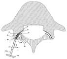
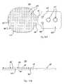
- FIGS. 1A and 1Billustrate a facet joint 20 composed of a superior articular facet 22 and an inferior articular facet 24 .
- the superior articular facet 22is formed by the vertebral level below the intervertebral disc (i.e., a superior articular facet projects upward from the junction of the lamina and the pedicle), whereas the inferior articular facet 24 is formed by the vertebral level above the intervertebral disc (i.e., an inferior articular facet projects downward).
- On the superior articular facet 22is a superior articular face 26
- the inferior articular facet 24is an inferior articular face 28 .
- Facet jointsare oriented obliquely to the sagittal plane, and the joint space itself is curved from front to back.
- the more posteriorly located inferior face 28is convex, whereas the more interiorly located superior face 26 is concave.
- the facet joint 20is a synovial joint; effectively defined by the two opposing bony faces 26 , 28 with cartilage 30 between them and a capsule 32 around the joint 20 .
- synovial fluid 34is contained inside the joint 20 by the capsule 32 , that is otherwise a water-tight sac of soft tissue and ligaments that fully surrounds and encloses the joint 20 , and keeps the joint faces 26 , 28 lubricated.
- the ends of the bone articular facets 22 , 24 that make up the synovial facet joint 20are normally covered with the articular, hyaline cartilage 30 that allows the bony faces 26 , 28 to glide against one another, providing the flexibility that allows the movement of vertebral bodies relative to one another.
- each pair of vertebraethere are two facet joints between each pair of vertebrae, one on each side (located posterior and lateral of the vertebral centerline), from the top and bottom of each vertebra.
- the jointscombine with the disc space to create a three joint complex at each vertebral level, and each joint extends and overlaps neighboring vertebral facet joints, linking each other and hence the vertebra together.
- the assembly of two vertebral bodies, the interposed spinal disc and the attached ligaments, muscles, and facet jointsis referred to as a “spinal motion segment”.
- Each motion segmentcontributes the overall flexibility of the spine and contributes to the overall ability of the spine to provide support for the movement of the trunk and head, and in particular, the facet joints limit torsional (twisting) motion.
- torsionaltilting
- the functional role of the facet joints in a spinal motion segmentis thus relevant to an understanding of the operative and functional advantages of the facet joint systems and methods disclosed herein, which achieve dynamic stabilization and mobility preservation without constraining motion in any plane.
- anteriorrefers to in front of the spinal column, and “posterior” refers to behind the column; “cephalad” means towards a patient's head (sometimes referred to as “superior”); and “caudal” (sometimes referred to as “inferior”) refers to the direction or location that is closer to the patient's feet.
- proximal and distalare defined in context of this channel of approach.
- proximalis closer to the beginning of the channel and thus closer to the clinician, and “distal” is further from the beginning of the channel and thus more distant from the clinician.
- distalwould be the end intended for insertion into the access channel, and “proximal” refers to the opposing end, generally the end closer to the handle of the delivery tool.
- distalwould be the leading end first inserted into the joint and “proximal” refers to the trailing end, generally in an engagement with a deployment tool.
- Facet jointscan be arthritic due to degeneration with aging, trauma, or disease (e.g., pathologies that include inflammatory, metabolic, or synovial, disorders).
- fractures, torn ligaments, and disc problemse.g., dehydration or herniation
- osteophitesi.e., bone spurs.
- the spursform around the edges of the facet joint, the joint becomes enlarged, a condition called hypertrophy, and eventually the joint surfaces become arthritic.
- the articular cartilagedegenerates or wears away, the bone underneath is uncovered and rubs against bone. The joint thus becomes inflamed, swollen, and painful.
- Facet joint arthritisis a significant source of neck and back pain, and is attributable to about 15-30% of persistent lower back pain complaints.
- facet joint painsuch as intra-articular steroids/local anesthetic injections administered under fluoroscopic guidance
- some patients with chronic painmay eventually require surgical intervention for facet joint arthritis including, for example, facet rhizotomy; facet ectomony to remove the facet joint to reduce pressure on the exiting nerve root; total joint replacement or facet arthrodesis (i.e., fixation leading to fusion, where the two articulating surfaces of the joint remain immobile or grow solidly together and form a single, solid piece of bone); etc.
- facet joint capsulesare primarily loaded in flexion and in rotation, and the facet joints are the primary resistors against rotational or torsional forces (e.g., normally, the facet joints control approximately 30% of axial rotation), facet joint degeneration significantly alters spinal mobility.
- One therapyfacet rhizotomy, involves techniques that sever small nerves that go to the facet joint. The intent of the procedure is to stop the transmission of pain impulses along these nerves.
- the nerve(s)is identified using a diagnostic injection. Then, the surgeon inserts a large, hollow needle through the tissues in the low back. A radiofrequency probe is inserted through the needle, and a fluoroscope is used to guide the probe toward the nerve. The probe is slowly heated until the nerve is severed. Another technique using pulsed radiofrequency does not actually burn the nerve, rather it is believed to stun the nerve.
- Yet another techniqueinvolves denervation by probe tip freezing, and still another procedure involves carefully controlled injection of botox toxin to treat muscle spasm, a protective reflex that may occur when the facets are inflamed that in turn causes the nearby muscles that parallel the spine to go into spasm. While these procedures may provide pain relief, they do not address ongoing joint degeneration (e.g., wear on articulating surfaces), which leads to kinematic and biomechanical dysfunction that may in turn lead to transition syndrome (i.e., progression of degeneration and pain to other joints) at other levels.
- transition syndromei.e., progression of degeneration and pain to other joints
- prosthetic total joint replacement of damaged facet jointsWhile certain clinicians have advocated prosthetic total joint replacement of damaged facet joints, in practice, it is difficult to implement such a prosthesis for a variety of reasons including the variability of facet joint geometry from facet joint to facet joint, and the high level of interaction between the facet joint and the other components in the spinal column. Moreover, joint replacement is a highly invasive and time-consuming procedure, requiring pre-preparation of joint surfaces and removal of bone, and thus there are associated risks, including blood loss and morbidity, increased anesthesia time, and increased convalescence time.
- a related therapeutic treatment of the facet jointentails the provision of an artificial facet joint where the inferior facet segment, the mating superior facet segment, or both, are covered with a cap (i.e., over all, or substantially all, of the facet).
- a capi.e., over all, or substantially all, of the facet.
- One such device and related method of implantationis described in Fitz, U.S. Pat. No. RE 36,758. While potentially viable, the capping of the facet segments has several potential disadvantages. Clinical concerns are believed to result from the disruption of the periosteum and ligamenturn teres femoris, both serving a nutrition delivery role to the femoral head, thereby leading to avascular necrosis of the bony support structure for the cap.
- Another therapeutic treatment of the facet jointis to affix the superior articular process to the inferior articular process using a facet screw.
- fixation therapymay alleviate symptoms associated with a degenerated facet joint, it also sacrifices some of the ability of the motion segment to move and thus sacrifices some of the ability of the spinal column to move in a natural manner.
- Central and lateral spinal stenosisjoint narrowing
- degenerative spondylolisthesismay all result from the abnormal mechanical relationship between the anterior and posterior column structures and induce debilitating pain.
- the facet joint stabilization devicegenerally entails a superior body and an inferior body that, when combined, form an exteriorly threaded device. When inserted into the joint space, the inferior and superior bodies establish an engaged relationship with the corresponding inferior and superior bony faces of the facet joint anatomy, respectively, and are somewhat slidable relative to one another to facilitate near normal facet joint motion ability. While viable, areas for improvement remain, including retention, long-term functioning, and insertion techniques.
- An embodiment of the inventionis directed to a method of treating a facet joint of a patient.
- the facet jointincludes a superior facet having superior articular face and an inferior facet having an inferior articular face.
- a distal end of an implant delivery cannulais extended between the superior and inferior articular faces.
- the implant delivery cannulahas a channel extending therethrough.
- An implantis moved through the channel until the implant is between the superior and inferior articular faces while at least a portion of the implant is within the channel.
- the implantcomprises a first surface and a second surface.
- the implant delivery cannulais moved away from the superior and inferior articular faces so that the first surface is adjacent the superior articular face and the second surface is adjacent the inferior articular face.
- Another embodiment of the inventionis directed to a method of treating a facet joint of a patient.
- the facet jointincludes a superior facet having superior articular face and an inferior facet having an inferior articular face.
- a distal end of an implant delivery cannulais extended between the superior and inferior articular faces.
- the implant delivery cannulahas a channel extending therethrough.
- a superior resurfacing body and an inferior resurfacing bodyare positioned in an adjacent relationship proximate a distal end of a pusher tool.
- the superior resurfacing body and the inferior resurfacing bodyare maintained in a desired position with respect to the pusher tool with an alignment guide and a recess.
- a first one of the alignment guide and the recessis provided on the superior and inferior resurfacing bodies and a second one of the alignment guide and the recess is provided on the pusher tool.
- the recessis adapted to receive at least a portion of the alignment guide.
- the superior and inferior resurfacing bodiesare moved through the channel with the pusher tool until the superior and inferior resurfacing bodies are between the superior and inferior articular faces while at least a portion of the superior and inferior resurfacing bodies are within the channel.
- the implant delivery cannulais moved away from the superior and inferior articular faces so that the superior resurfacing body is adjacent the superior articular face and wherein the inferior resurfacing body is adjacent the inferior articular face.
- the pusher toolis moved away from the superior and inferior articular faces.
- Another embodiment of the inventionis directed to a method of treating a facet joint of a patient.
- the facet jointincludes a superior facet having superior articular face and an inferior facet having an inferior articular face.
- a distal end of an implant delivery cannulais extended between the superior and inferior articular faces.
- the implant delivery cannulahas a channel extending therethrough.
- a superior resurfacing body and an inferior resurfacing bodyare positioned in an adjacent relationship proximate a distal end of a pusher tool.
- the superior resurfacing body and the inferior resurfacing bodyeach include an articulating surface and an engagement surface on opposite sides thereof.
- the articulating surfaceis substantially smooth.
- the engagement surfacehas a plurality of teeth extending therefrom.
- the superior and inferior resurfacing bodiesare moved through the channel with the pusher tool until the superior and inferior resurfacing bodies are between the superior and inferior articular faces while at least a portion of the superior and inferior resurfacing bides are within the channel.
- the implant delivery cannulais moved away from the superior and inferior articular faces so that the plurality of teeth on the superior resurfacing body engage the superior articular face and the plurality of teeth on the inferior resurfacing body engage the inferior articular face.
- the articulating surfaces on the superior resurfacing body and the inferior resurfacing bodyare adjacent.
- the pusher toolis moved away from the superior and inferior articular faces.
- FIG. 1Ais a simplified cross-sectional view of a human spinal segment illustrating anatomy of native facet joints with which the systems and methods of the present disclosure are useful in treating;
- FIG. 1Bis an enlarged view of one facet joint of the segment of FIG. 1A ;
- FIG. 2is a perspective view of a facet joint treatment system in accordance with principles of the present disclosure
- FIG. 3Ais a top view of a resurfacing device component of the system of FIG. 2 ;
- FIG. 3Bis a cross-sectional view of the resurfacing device of FIG. 3A , taken along the line 3 B- 3 B;
- FIG. 3Cis an enlarged view of a portion of the device of FIG. 3B , taken along the line 3 C;
- FIG. 3Dis a front view of the resurfacing device of FIG. 3A ;
- FIG. 4Ais a perspective view of an alternative resurfacing device useful with facet joint treatment systems of the present disclosure
- FIG. 4Bis a perspective view of another resurfacing device useful with facet joint treatment systems of the present disclosure.
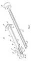
- FIG. 5is a perspective, exploded view of an insertion tooling set useful in inserting the facet joint treatment systems of the present disclosure
- FIG. 6Ais a side sectional view of a delivery cannula assembly component of the tooling set of FIG. 5 ;
- FIG. 6Bis a cross-sectional view of the cannula assembly of FIG. 6A , taken along the line 6 B- 6 B;
- FIG. 6Cis a size view of the cannula assembly of FIG. 6A , loaded with the facet joint treatment system of FIG. 2 ;
- FIG. 6Dis a cross-sectional view of the loaded cannula assembly of FIG. 6C , taken along the lines 6 D- 6 D;
- FIG. 6Eis an enlarged, top perspective view of a portion of the delivery cannula assembly of FIG. 5 ;
- FIG. 7Ais a perspective view of a pusher tool component of the tooling set of FIG. 5 ;
- FIG. 7Bis an enlarged plan view of a distal portion of the pusher tool of FIG. 7A engaging a resurfacing device in accordance with principles of the present disclosure
- FIGS. 8A-8Cillustrate loading and operation of the tooling set of FIG. 5 in deploying the facet joint treatment system of FIG. 2 ;
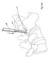
- FIG. 9illustrates accessing a facet joint in preparation for subsequent resurfacing device insertion into the joint in accordance with principles of the present disclosure
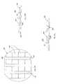
- FIGS. 10A-10Cillustrate use of optional dilator and sheath instruments in accordance with the present disclosure
- FIGS. 11A-11Cillustrate deployment of the facet joint treatment system of FIG. 2 within a facet joint using the tooling set of FIG. 5 ;
- FIG. 11Dis an enlarged, cross-sectional view of a facet joint within which the treatment system of FIG. 2 has been inserted;
- FIG. 12Ais a top plan view of another resurfacing device useful with facet joint treatment systems in accordance with principles of the present disclosure
- FIG. 12Bis a side view of the resurfacing device of FIG. 12A ;
- FIG. 12Cis a front view of the resurfacing device of FIG. 12A ;
- FIG. 13Ais a top plan view of another resurfacing device useful with facet joint treatment systems in accordance with principles of the present disclosure
- FIG. 13Bis a side view of the resurfacing device of FIG. 13A ;
- FIG. 13Cis a front view of the resurfacing device of FIG. 13A ;
- FIG. 14Ais a top plan view of another resurfacing device useful with facet joint treatment systems in accordance with principles of the present disclosure
- FIG. 14Bis a side view of the resurfacing device of FIG. 14A ;
- FIG. 14Cis a front view of the resurfacing device of FIG. 14A ;
- FIG. 15Ais a top plan view of another resurfacing device useful with facet joint treatment systems in accordance with principles of the present disclosure
- FIG. 15Bis a side view of the resurfacing device of FIG. 15A ;
- FIG. 15Cis a front view of the resurfacing device of FIG. 15A ;
- FIG. 16Ais a top plan view of another resurfacing device useful with facet joint treatment systems in accordance with principles of the present disclosure
- FIG. 16Bis a side view of the resurfacing device of FIG. 16A ;
- FIG. 17Ais a top plan view of another resurfacing device useful with facet joint treatment systems in accordance with principles of the present disclosure
- FIG. 17Bis a side view of the resurfacing device of FIG. 17A ;
- FIG. 18Ais a top plan view of another resurfacing device useful with facet joint treatment system in accordance with principles of the present disclosure
- FIG. 18Bis a side view of the resurfacing device of FIG. 18A ;
- FIG. 19Ais a top plan view of another resurfacing device useful with facet joint treatment systems in accordance with principles of the present disclosure.
- FIG. 19Bis a side view of the resurfacing device of FIG. 19A ;
- FIG. 20Ais a top plan view of another resurfacing device useful with facet joint treatment systems in accordance with principles of the present disclosure
- FIG. 20Bis a side view of the resurfacing device of FIG. 20A ;
- FIG. 21Ais a side view of another facet joint treatment system in accordance with principles of the present disclosure.
- FIG. 21Bis a front view of the system of FIG. 21A ;
- FIG. 21Cis a top plan view of the system of FIG. 21A ;
- FIG. 22Ais a front perspective view of another facet joint treatment system in accordance with principles of the present disclosure.
- FIG. 22Bis a side, exploded view of the system of FIG. 22A ;
- FIG. 23is a sectional view of a facet joint to which another facet joint treatment system of the present disclosure is implanted;
- FIG. 24Ais a side, exploded view of another facet joint treatment system of the present disclosure.
- FIG. 24Bis a sectional view of the system of FIG. 24A implanted to a facet joint;
- FIG. 25Ais a perspective view of a portion of another facet joint treatment system of the present disclosure.
- FIG. 25Bis a side view of the system of FIG. 25A ;
- FIG. 25Cis a simplified perspective view of the system of FIG. 25B implanted to a facet joint.
- FIG. 2One embodiment of a system 40 in accordance with principles of the present disclosure and useful for treating a facet joint of a patient is shown in FIG. 2 .
- the system 40includes a superior resurfacing device 42 and an inferior resurfacing device 44 . Details on the various components are provided below.
- the resurfacing devices 42 , 44can be identical, with the superior resurfacing device 42 serving as a liner for a superior facet joint articular face (e.g., the superior articular face 26 of FIG. 1B ), and the inferior resurfacing device 44 serving as a liner for an inferior facet joint articular face (e.g., the inferior articular face 28 of FIG. 1B ).
- the resurfacing devices 42 , 44are capable of substantially conforming to the naturally-occurring shape or curvature of the facet joint anatomy, and replace the existing, bone-on-bone interface of the natural facet joint in a manner achieving normal or near normal mobility.
- the resurfacing devices 42 , 44can be identical. Thus, the following description of the superior resurfacing device 42 is equally applicable to the inferior resurfacing device 44 .
- the resurfacing device 42consists of a resurfacing body 46 . In other embodiments described below, one or more additional components can be attached to, or extend from, the resurfacing body 46 .
- the resurfacing body 46has a disc-like shape, and includes a base web 50 and a plurality of teeth 52 (referenced generally). The base web 50 defines opposing major surfaces 54 , 56 (best shown in FIG.
- first major surface 54provides or serving as an articulating surface (e.g., articulates relative to a corresponding articulating surface of the inferior resurfacing device 44 ( FIG. 2 )) as described below.
- first major surface 54can also be referenced as the “articulating surface” of the resurfacing body 46 .
- the plurality of teeth 52project from the second major surface 56 in a direction generally opposite the first major surface 54 .
- the base web 50defines an outer perimeter 58 (referenced generally) of the resurfacing body 46 , with the perimeter 58 having an oval-like shape (relative to a top or bottom plan view) in some constructions. More particularly, the perimeter 58 , and thus the resurfacing body 46 , defines a major diameter MA along a major axis thereof, and a minor diameter MI along a minor axis thereof.
- An overall size or footprint of the resurfacing body 46is defined by the perimeter 58 and can vary depending upon a size of the facet joint being treated, but is generally relatively small, especially as compared to conventional facet joint prostheses and/or capping devices.
- the major diameter MAcan be in the range of 5-12 mm
- the minor diameter MIcan be in the range of 4-10 mm in some embodiments.
- facet joint treatment systems in accordance with the present disclosurecan be provided to a treating clinician with two or more different superior resurfacing devices 42 (and two or more different inferior resurfacing devices 44 ) each having a differently-sized resurfacing body 46 (e.g., 5 mm ⁇ 4 mm; 8 mm ⁇ 6 mm; 10 mm ⁇ 8 mm; 11 mm ⁇ 9 mm; 12 mm ⁇ 10 mm, etc.), with the treating clinician selecting the most appropriately sized resurfacing device for implantation based upon an evaluation of the facet joint to be treated.
- the perimeter 58need not necessarily be oval in shape. Instead, other shapes (e.g., circular, square, rectangular, curvilinear, etc.) are also acceptable.
- the resurfacing body 46can incorporate one or more features dictating a preferred insertion orientation and/or direction (i.e., the resurfacing body 46 is more readily inserted into, and subsequently retained within, a facet joint in a particular orientation).
- the perimeter 58can be described as generally defining a leading or distal end 70 , a trailing or proximal end 72 , and opposing sides 74 , 76 .
- the minor diameter MIintersects the leading and trailing ends 70 , 72 , whereas the opposing sides 74 , 76 are aligned along the major diameter MA.
- the resurfacing body 46is oriented such that the leading end 70 is initially inserted into the facet joint, followed by the trailing end 72 .
- the trailing end 72can form or define an engagement feature 80 (referenced generally) that promotes desired interaction with a separately-provided insertion tool (not shown) described below.
- the engagement feature 80can be a notch 82 formed in the base web 50 at the trailing end 72 .
- the notch 82can assume various shapes, and in some constructions, is defined as a 90° cut into the base web 50 .
- the notch 82can have shapes differing from that illustrated, and the engagement feature 80 can assume other formats that may or may not include the notch 82 .
- the engagement feature 80is omitted.
- the base web 50has, in some constructions, a relatively uniform thickness t (e.g., nominal thickness variation of +/ ⁇ 0.05 mm). Regardless, the base web 50 forms the articulating surface 54 to be highly smooth. This smoothness attribute is, at least in part, a function of the material employed for the resurfacing body 46 as described below. In other embodiments, the articulating surface 54 of the base web 50 can be coated with a separate layer that provides enhanced frictional (i.e., lower coefficient of friction) and wear characteristics.
- the plurality of teeth 52project from the second major surface 56 of the base web 50 , and can assume a variety of forms.
- the teeth 52are arranged to form or define discrete zones or teeth sets, such as the teeth sets 90 , 92 , 94 generally identified in FIG. 3A .
- the first teeth set 90is centrally located along the base web 50 extending between the leading and trailing ends 70 , 72 .
- Individual teeth of the first teeth set 90are generally identical, with a leading tooth 96 a of the first teeth set 90 being shown in greater detail in FIG. 3C . More particularly, the tooth 96 a includes a leading face 98 and a trailing face 100 that extend from the second major surface 56 and intersect at a tip 102 .
- the leading face 98is more proximate the leading end 70 (as compared to the trailing face 100 ), whereas the trailing face 100 is more proximate the trailing end 72 ( FIG. 3B ).
- the tooth 96 ais constructed to define an insertion direction whereby an angle ⁇ formed by the leading face 98 relative to the second major surface 56 is less than an angle ⁇ formed by the trailing face 100 relative to the second major surface 56 .
- the leading face 98has a more gradual slope relative to the leading end 70 as compared to a slope of the trailing face 100 relative to the trailing end 72 such that the tooth 96 a more overtly engages a separate structure, such as the facet joint superior face (not shown) at and along the trailing face 100 as compared to the leading face 98 .
- the angle ⁇ defined by the leading face 98is in the range of 20°-60°, whereas the angle ⁇ defined by the trailing face 100 is approximately 90°. Other angles are also acceptable.
- the remaining teeth of the first teeth set 90are aligned with one another in two or more rows as shown.
- the second teeth set 92 and the third teeth set 94are formed at or along the opposing sides 74 , 76 , respectively.
- an exterior face 104 associated with each tooth of the second and third teeth sets 92 , 94establish an angle of extension relative to the second major surface 56 that approaches 90° as best shown in FIG. 3D in some embodiments.
- the second and third teeth sets 92 , 94overtly resist side-to-side displacement of the resurfacing body 46 relative to a corresponding facet joint face following insertion (e.g., relative to the orientation of FIG. 3D , the second teeth set 92 resists leftward displacement of the resurfacing body 46 , whereas the third teeth set 94 resists rightward displacement).
- each tooth of the plurality of teeth 52can have an identical, or nearly identical, height (or extension from the second major surface 56 ).
- the teeth of the first teeth set 90have an elevated height as compared to teeth of the second and third teeth sets 92 , 94 ( FIG. 3A ), and combine to define a tapering height of the resurfacing body 46 from the leading end 70 to the trailing end 72 .
- a height of the leading tooth 96 ais greater than a height of a trailing tooth 96 b .
- the tips 102 associated with the teeth of the first teeth set 90combine to define a hypothetical plane P.
- the plane Pis, in some embodiments, non-perpendicular relative to a plane of the first major surface 54 , combining with the first major surface 54 to define an included angle ⁇ in the range of 1°-5°.
- the teeth 52have identical heights.
- the tallest tooth 96 ais provided at the leading end 70 that ultimately is located opposite the point of insertion into the facet joint.
- the leading tooth 96 acan desirably establish a more rigid engagement with the corresponding facet joint face to thereby overtly resist displacement upon final insertion.
- the base web 50 and the teeth 52combine to define an overall thickness T of the resurfacing body 46 (e.g., lateral distance between the first major surface 54 and the tip 102 of the “tallest” tooth 96 a ).
- an overall thickness T of the resurfacing body 46e.g., lateral distance between the first major surface 54 and the tip 102 of the “tallest” tooth 96 a .
- a desired conformability characteristic of the resurfacing body 46is influenced by the overall thickness T and the base web thickness t, and thus the overall thickness T is selected, along with other parameters, to effectuate the desired degree of conformability.
- the overall thickness T of the resurfacing body 46is in the range of 0.25-4 mm, although other dimensions are also contemplated.
- the overall thickness T associated with the resurfacing body 46 selected by the treating clinician for insertion into a particular facet jointmay vary as a function of other procedures associated with the insertion.
- the overall thickness Tcan be in the range of 0.5-2.5 mm. If, however, the insertion procedure entails first removing cartilage (or other tissue) from the facet joint, a larger version of the resurfacing body 46 can be inserted, such that the overall thickness T of the resurfacing body 46 is in the range of 0.5-3 mm.
- FIGS. 4A and 4Billustrate alternative resurfacing bodies 46 ′, 46 ′′, respectively, in accordance with principles of the present disclosure.
- the resurfacing body 46 ′ of FIG. 4Aincorporates an increased number of teeth 52 ′.
- some of the teeth 52 ′′are arranged in discretely spaced rows.
- the teethcan be replaced or augmented with other features (e.g., surface textures or coatings) that promote retention in the facet joint, bony in-growth, or both.
- the resurfacing devices 42 , 44are each integrally formed of a robust material that achieves desired conformability.
- the resurfacing body 46in accordance with the present disclosure maintains its structural integrity (i.e., little or no wear) without adhesive or cohesive damage when subjected to typical articulation of the facet joint with movement of the patient.
- the resurfacing devices 42 , 44are formed of an implantable-grade plastic, although other materials such as metal are also available.
- the resurfacing devices 42 , 44can be made from the polyetherketone (PEK) family of plastics, which have strength, wear, flexibility, and biocompatibility properties appropriate for insertion into, and long-term functioning within, the facet joint.
- PEKpolyetherketone
- PEEKpolyetheretherketone
- Additional material(s)can be incorporated, such as those exhibiting radio-opacity properties.
- the resurfacing devices 42 , 44can be formed from a radio-opaque mineral (e.g., barium)-loaded PEK composition. Visualization can also be provided via one or more radio-opaque marker bands (e.g., platinum marker band).
- the marker band(s)can be embedded within the resurfacing device 42 , 44 (e.g., a radio-opaque rod inserted into a hole formed in the resurfacing device 42 , 44 ); inserted around a perimeter of the resurfacing device 42 , 44 ; etc.
- the selected materials, shapes, and dimensions associated with the resurfacing body 46 of each of the resurfacing devices 42 , 44impart or create a conformability property to the resurfacing body 46 sufficient to allow the resurfacing body 46 to “match” the multi-planar concavity associated with a native facet joint articular face anatomy.
- the resurfacing body 46forms an entirety of the corresponding resurfacing device 42 , 44 .
- one or more additional componentscan be included with the resurfacing body 46 , such that the following explanation of conformability is specifically applicable to the resurfacing body 46 , but may also apply equally to the resurfacing devices 42 , 44 as a whole.
- “conformability”is inversely proportional to bending stiffness of the resurfacing body 46 during insertion, and may be increased as the resurfacing body 46 heats to body temperature and is allowed to creep. From a clinical perspective, “conformability” of the resurfacing body 46 entails the resurfacing body 46 conforming to a radius of curvature of the C-shaped or J-shaped portions of the articular joint (e.g., the concave-shaped superior articular face 26 of FIG. 1B or the convex-shaped inferior articular face 28 of FIG. 1B ).
- the minimum radius of curvature of the human facet joint in the transverse planeis on the order of 20 mm, with a lower bound (10 th percentile) on the order of 7 mm.
- the radius of curvaturewill vary with the vertebral level and the patient's specific anatomy and disease state. Preparation of the facet joint prior to insertion of the resurfacing devices 42 , 44 may also change the radius of curvature.
- a range of curvature radii of 7 mm to infinityi.e., flat facet anatomy
- the conformability characteristic of the resurfacing body 46is sufficient such that the resurfacing body 46 readily transition from the relatively flat state illustrated in FIG. 2 to an inserted state (not shown but reflected, for example, in FIG. 11D ) in which the resurfacing body 46 substantially matches or mimics the naturally-occurring shape (e.g., radius of curvature of curved portions) of the facet joint face to which the resurfacing body 46 is secured.
- the facet joint 20( FIG. 1B ) is subject to, or experiences, various loads that effectuate compressive forces at the region of interface between the superior and inferior articular faces 26 , 28 ( FIG. 1B ).
- the conformable nature of the resurfacing body 46is such that in the presence of these typical compressive forces, the resurfacing body 46 will transition from the relatively flat state to the inserted state in which the resurfacing body 46 substantially matches the geometry of the facet joint surface to which the resurfacing body 46 is secured (i.e., the resurfacing body 46 will flex to conform with a macroscopic shape/contour of the native articular face to which the resurfacing body 46 is applied, but may not conform to the microscopic variations in the native articular face, for example small deviations due to cartilage defects, bony fissures, or small voids during preparation of the joint (typically 0.05-0.5 mm in width)).
- a resurfacing body that conforms to the minimum radius of curvature of an adult human facet joint under normal physiologic forces (e.g., on the order of 180-450 N/mm per segment assuming a net 1 mm posterior shear translation) without deviations from the articular surface to which the resurfacing body is applied of greater than 1 mmis defined as being “conformable” and “substantially matching” the multi-planar curvatures of a facet joint.
- a resurfacing body sized for placement within an adult human facet joint and exhibiting a Conformability Factor (described below) of not more than 100 Nis also defined as being “conformable” and “substantially matching” the multi-planar curvatures of a facet joint in accordance with the present disclosure.
- resurfacing bodies in accordance with the present disclosureexhibit a Conformability Factor of not more than 50 N, and in other embodiments not more than 25 N. It has surprisingly been found that forming the resurfacing body 46 (and thus either of the resurfacing devices 42 , 44 of the one embodiment of FIG. 2 ) of PEEK and with the footprint size and thickness dimensions described above achieves the desired conformability characteristics, long-term resistance to wear, and facet joint stabilization following insertion.
- the resurfacing body 46can be delivered to, and inserted within, a facet joint in a variety of manners via various instrumentations sets or systems.
- Components of one useful insertion tooling set 150is shown in FIG. 5 , and includes a delivery cannula assembly 152 and a pusher tool 154 .
- the delivery cannula assembly 152is sized to slidably receive the pusher tool 154 and the resurfacing devices 42 , 44 ( FIG. 2 ), with the cannula assembly 152 and the pusher tool 154 being operable to insert the resurfacing devices 42 , 44 into a facet joint.
- the tooling set 150can optionally further include a guide pin 156 and a retention cap 158 .
- the delivery cannula assembly 152includes, in some constructions, a cannula body 160 , guide arms 162 a , 162 b , and a handle 164 .
- the cannula body 160forms or defines a distal section 170 terminating at a distal end 172 , and a proximal section 174 terminating at a proximal end 176 .
- the cannula body 160forms an internal passage 178 ( FIGS. 6A and 6B ) that extends between, and is open relative to, the distal and proximal ends 172 , 176 .
- the internal passage 178is sized and shaped in accordance with a combined size and shape of the resurfacing devices 42 , 44 ( FIG. 2 ). More particularly, the internal passage 178 is sized to slidably receive and maintain the resurfacing devices 42 , 44 when arranged or stacked against one another in a mirror-like fashion. For example, as shown in FIGS. 6C and 6D , the internal passage 178 is sized and shaped such that the resurfacing devices 42 , 44 are maintained therein, with the articulating surface 54 of the superior resurfacing device 42 abutting the articulating surface 54 of the inferior resurfacing device 44 .
- a height of the internal passage 178corresponds with, or is slightly greater than, a combined thickness of the resurfacing devices 42 , 44 .
- the cannula body 160forms one or more interior ribs 180 (best shown in FIGS. 6B and 6D ) projecting within the internal passage 178 .
- FIG. 6Bdepicts one embodiment including a pair of spaced-apart upper ribs 180 a , 180 b and a pair of spaced-apart lower ribs 180 c , 180 d .
- the rib(s) 180extend longitudinally relative to the internal passage 178 , and are sized (e.g., in terms of width and distance or length of projection into the internal passage 178 ) to be slidably received between the teeth 52 of the corresponding resurfacing device 42 , 44 (e.g., in some embodiments, various ones of the teeth 52 are aligned with one another to collectively define a channel across the resurfacing device 42 , 44 that is sized to slidably receive one of the ribs 180 ).
- the teeth 52 of the corresponding resurfacing device 42 , 44e.g., in some embodiments, various ones of the teeth 52 are aligned with one another to collectively define a channel across the resurfacing device 42 , 44 that is sized to slidably receive one of the ribs 180 ).
- a horizontal gap between opposing ones of the ribs 180corresponds with, or is slightly greater than, a combined thickness of the base webs 50 of the resurfacing devices 42 , 44 .
- the ribs 180serve to guide the resurfacing devices 42 , 44 when longitudinally moved through the internal passage 178 , thereby preventing undesired rotation thereof.
- the internal passage 178is defined by a width corresponding with the major diameter MA ( FIG. 3A ).
- the internal passage 178can have a width of approximately 11.7 mm.
- Other dimensionsare also acceptable so long as the resurfacing devices 42 , 44 can be slidably retained within the internal passage 178 in the stacked arrangement shown.
- the distal section 170can include or form one or more features that facilitate desired positioning of the tooling set 150 during use and/or operation thereof.
- the cannula body 160can be defined as having a first major surface 182 (also identified in FIG. 6A ) and an opposing, second major surface 184 .
- a slot 186is formed in the distal section 170 along the second major surface 184 in some constructions.
- the slot 186is open to the internal passage 178 , and extends from, and is open relative to, the distal end 172 .
- the slot 186extends between and terminates at a proximal side 188 and a distal side 190 , and is sized to slidably receive a corresponding component of the pin 156 ( FIG. 5 ) as described below.
- the distal section 170further provides or forms an optional shoulder 192 along the first major surface 182 as best shown in FIG. 6A .
- the shoulder 192can assume a variety of forms differing from those reflected in the drawings, and in more general terms defines an enlarged stop surface 194 at the distal end 172 .
- the stop surface 194is configured to better ensure desired positioning of the guide arms 162 a , 162 b relative to a facet joint during an insertion procedure as described below.
- the shoulder 192can be omitted.
- the guide arms 162 a , 162 bare connected to, and extend from, the distal end 172 of the cannula body 160 , each terminating at a distal tip 196 a , 196 b , respectively.
- the guide arms 162 a , 162 bare rigid yet flexible (akin to a metal tape), and can deflect away from one another from the natural, pre-insertion arrangement of FIGS. 5 and 6E .
- the guide arms 162 a , 162 bare readily insertable into a confined space (e.g., a facet joint) with the distal tips 196 a , 196 b contacting, or nearly contacting, one another at least at the corresponding tips 196 a , 196 b . Subsequently, as the stacked resurfacing devices 42 , 44 ( FIG. 6C ) are forced between the guide arms 162 a , 162 b , the distal tips 196 a , 196 b will splay away from one another, with the guide arms 162 a , 162 b deflecting at the distal end 172 of the cannula body 160 .
- a confined spacee.g., a facet joint
- the slot 186can terminate proximal the second guide arm 162 b as shown.
- the second guide arm 162 bcan form a slot segment that serves as a continuation of the slot 186 .
- An arrangement of the distal side of the slot 186e.g., the distal side 190 ) relative to the distal tips 196 a , 196 b , as well as a length of the slot 186 , are selected to effectuate optimal insertion of the resurfacing devices 42 , 44 ( FIG. 2 ) via the cannula assembly 152 and the pusher tool 154 as described below.
- the handle 164extends radially from the proximal end 176 of the cannula body 160 .
- the internal passage 178( FIG. 6A ) extends through, and is open at, a proximal face 200 of the handle 164 .
- the handle 164is configured to facilitate not only handling of the tool set 150 by a user, but can also serve to ensure or limit movement of the pusher tool 154 relative to the cannula body 160 .
- the pusher tool 154is shown in greater detail in FIG. 7A , and is generally formed as an elongate body forming a hole 208 , and defining a distal end 210 and a proximal end 212 .
- the hole 208is sized to frictionally receive a component of the pin 156 ( FIG. 5 ) as described below, and is formed at a distance from the distal end 210 selected to facilitate deployment of the resurfacing devices 42 , 44 ( FIG. 2 ) in a desired fashion.
- the pusher tool 154is sized to be slidably received within the internal passage 178 ( FIG. 6A ) of the cannula body 160 ( FIG. 5 ), and thus has a size and shape corresponding with that of the internal passage 178 .
- the pusher tool 154can form longitudinal channels 214 sized to slidably receive respective ones of the ribs 180 .
- the distal end 210is configured to interface with the stacked resurfacing devices 42 , 44 ( FIG. 6D ), and in some embodiments can incorporate one or more features that promote a more robust interface with the stacked resurfacing devices 42 , 44 .
- the distal end 210can include or form a central finger 216 defined between opposing grooves 218 a , 218 b .
- the finger 216can assume a variety of shapes and dimensions, and is generally sized in accordance with the notch 82 ( FIG. 3A ) of the corresponding resurfacing bodies 46 .
- the grooves 218 a , 218 bare generally shaped in accordance with a shape of the trailing end 72 ( FIG.
- abutting contact between the distal end 210 and the trailing end 72 of the resurfacing body 46 of the superior resurfacing device 42includes the finger 216 nesting within the notch 82 , and the trailing end 72 disposed within the grooves 218 a , 218 b .
- the opportunity for undesired rotation of the resurfacing body 46 relative to the distal end 210is reduced, yet a sufficient surface area interface between the distal end 210 and the resurfacing body 46 is provided such that the pusher tool 154 can readily be employed to distally move the contacted resurfacing body 46 (and thus the stacked resurfacing devices 42 , 44 as a collective unit).
- the finger 216is provided with the tool 154 and the notch 82 is formed by the resurfacing bodies 46 ; alternatively, the resurfacing bodies 46 can include a finger, with the pusher tool 154 forming a corresponding notch.
- the finger 216is configured to provide a more secure (but releasable) attachment between the pusher tool 154 and the resurfacing devices 42 , 44 so that the devices 42 , 44 can be both pushed and pulled relative to the pusher tool 154 (and thus relative to the facet joint being resurfaced).
- the optional guide pin 156includes a shaft 220 and a grip 222 .
- the shaft 220is sized to be insertable through the slot 186 (e.g., a diameter of the shaft 220 is less than a width of the slot 186 ), and to be received and frictionally retained at the hole 208 in the pusher tool 154 .
- the grip 222is dimensioned to be larger than the slot 186 (e.g., the grip 222 cannot pass through the slot 186 ), with a length of the shaft 220 being greater than a thickness of the cannula body 160 wall at which the slot 186 is formed.
- the shaft 220can be inserted through the slot 186 (e.g., manually by a user otherwise grasping the pin 156 at the grip 222 ) and engaged with the pusher tool 154 . With sliding of the pusher tool 154 relative to the cannula body 160 , then, the shaft 220 slides within the slot 186 ; upon contacting the distal side 190 , the shaft 220 prevents further distal movement of the pusher tool 154 .
- the guide pin 156can be removed from the pusher tool 154 /cannula body 160 by manually retracting the shaft 220 from the hole 208 .
- the shaft 220can be formed as a permanent projection from the pusher tool 154 , and the separate guide pin 156 eliminated.
- the tooling set 150Prior to an insertion procedure, the tooling set 150 is loaded with the resurfacing devices 42 , 44 ( FIG. 2 ).
- the pusher tool 154is slidably disposed within the internal passage 178 ( FIG. 6B ) of the cannula body 160 , with the shaft 220 being slidably disposed within the slot 186 as shown in FIG. 8A (for purposes of explanation, the grip 222 ( FIG. 5 ) of the pin 156 ( FIG. 5 ) is omitted).
- loading of the pusher tool 154is described as occurring prior to loading of the resurfacing devices 42 , 44 .
- the resurfacing devices 42 , 44are initially placed into the internal passage 178 , followed by the pusher tool 154 .
- the proximal end 212 ( FIG. 5 ) of the pusher tool 154projects outwardly (proximally) beyond the proximal face 200 ( FIG. 5 ) of the handle 164 ( FIG. 5 ).
- the pusher tool 154is arranged relative to the cannula body 160 such that the shaft 220 is located adjacent the proximal side 188 of the slot 186 .
- the distal end 210 of the pusher tool 154is thus spaced from the distal end 172 of the cannula body 160 .
- the pusher tool 154can be captured relative thereto via the cap 158 ( FIG. 5 ) or other structure mounted to the proximal end 212 .
- the cap 158provides an enlarged surface for grasping by a user for subsequent manipulation of the pusher tool 154 relative to the cannula body 160 .
- the pin 156is retractable from the pusher tool 154 and the cannula body 160
- the stacked resurfacing devices 42 , 44 and the pusher tool 154can be inserted into the cannula body 160 proximally via the distal end 172 , or distally via the proximal end 176 ( FIG. 5 ).
- the stacked resurfacing devices 42 , 44are inserted into the internal passage 178 of the cannula body 160 as shown in FIG. 8B (as well as FIGS. 6C and 6D ).
- the stacked resurfacing devices 42 , 44(one of which is partially visible in FIG. 8B through the slot 186 ) can be inserted through the distal end 172 , and slid proximally toward the distal end 210 of the pusher tool 154 .
- the distal end 210engages the trailing end 72 of the corresponding resurfacing bodies 46 as described above, with the resurfacing devices 42 , 44 thus being located or disposed completely within the cannula body 160 .
- a distance between the proximal side 188 of the slot 186 and the distal end 172 of the cannula body 160is less than, or approximates, a combination of a length of the stacked resurfacing devices 42 , 44 and a distance between the distal end 210 of the pusher tool 154 and the shaft 220 .
- the pusher tool 154is moved distally relative to the delivery cannula assembly 152 , with the shaft 220 is sliding within the slot 186 .
- distal-most movement of the pusher tool 154 relative to the delivery cannula assembly 152is achieved with the shaft 220 abutting the distal side 190 of the slot 186 .
- a distance between the distal tips 196 a , 196 b of the guide arms 162 a , 162 b(it being understood that only the lower guide arm 162 b and the corresponding tip 196 b are visible in the view of FIG.
- the distal side 190 of the slot 186corresponds with a distance between the finger 216 (hidden in FIG. 8C , but visible in FIG. 7B ) and the shaft 220 such that with the shaft 220 at the distal side 190 , at least a majority of the resurfacing bodies 46 (one of which is visible in FIG. 8C ) are forced distally beyond the distal tips 196 a , 196 b .
- the resurfacing bodies 46are essentially (but not completely) deployed from the tooling set 150 .
- Engagement of the shaft 220 with the distal side 190 of the slot 186prevents further distal movement of the pusher tool 154 relative to the cannula body 160 .
- over-deployment of the resurfacing bodies 46 distally beyond the tooling set 150 (and perhaps beyond the facet joint 20 )is prevented.
- the tooling set 150 described aboveis but one possible configuration envisioned by the present disclosure and otherwise useful in deploying the resurfacing devices 42 , 44 within a facet joint.
- Other tooling sets and/or componentscan be employed as part of an insertion procedure.
- the assemblies, tools, and methods described in this disclosureare not limited to a specific method of access to the posterior of a motion segment facet joint.
- cervical facetsmay require a different operative approach (for example, posterior approach versus a posterior lateral approach) as well as modified access and preparation tool and resurfacing body dimensions, because of coronal angulation.
- precautionsare indicated in access and preparation of surgical sites, including use of an imaging system, e.g., bi-planar fluoroscopy, to help maintain interior/posterior and lateral alignment and facilitate surgery, and use of instrumentation with marking indicia in increments in millimeter as appropriate numbers to facilitate accuracy, and in particular with respect to the accurate placement and alignment of the resurfacing bodies 46 within the facet joint.
- an imaging systeme.g., bi-planar fluoroscopy
- the patientis placed in the prone position and x-ray imaging equipment is set-up to provide views in both the antero-posterior (AP) plane and the lateral plane so that the procedure can be performed under fluoroscopic guidance.
- APantero-posterior
- FIG. 9using fluoroscopy or image guidance, access to the facet joint 20 capsule and inter-articular space is achieved by advancing a guide wire or needle 250 through the soft tissue and docking a tip 252 of the guide wire 250 into the facet space 20 at a point corresponding with an end of the joint's principal articulating access.
- Contrast materialmay be injected to confirm the location of the guide wire 250 , especially at first, but with experience, confirmation of appropriate guide wire placement can be made by feel and by viewing antero-posterior and lateral projections.
- the joint access tract formed between the point of skin entry and docking at an end of the facet joint 20is typically at the facet joint 20 to be resurfaced, but can alternatively initiate one to two motion segment levels apart from the point of entry into the facet joint 20 of the planned resurfacing to allow for optimal insertion trajectory and placement.
- osteophytes on the posterior facetsmay be removed to provide better visualization, to help define the anatomy of the facets, and to provide a suitable surface to allow for therapies as set forth in this disclosure.
- Access to and preparation of a posterior target site on the spine, such as the posterior of the L5-S1 segment facet joints, and subsequent deployment therapy, e.g., the deployed resurfacing devices described above,may be performed following percutaneous entry, e.g., by means of a stab incision (the location of the incision may vary, dependent on individual patient anatomy), and by means of subsequent insertion of instrumentation systems including guide wire, dilators, cannulas, insertion tooling sets, as described herein.
- percutaneousmeans through the skin from an access point on the patient and to the posterior target point, as in transcutaneous or transdermal, without implying any particular procedure from other medical arts.
- percutaneousis distinct from an open surgical access, and the percutaneous opening in the skin is preferably minimized so that it is less than 4 cm across, preferably less than 2 cm.
- the percutaneous pathwayis generally aligned with the bore extending from the posterior target point through and into the facet joint 20 and into the articular space, as visualized by radiographic or fluoroscopic equipment.
- a cannulated dilator 254 having a conical, tapered distal end 256is advanced over the guide wire 250 into the point of entry in the facet joint 20 to create subcutaneous space for the working channel.
- a hammer or malletcan be used to dock the cannulated dilator 254 into the facet joint 20 . It will be understood, for example as needed for other anatomically located joint therapies, this process may be sequentially repeated as needed, i.e., by subsequently inserting a larger diameter cannulated dilator to successively enlarge the access tract.
- An enlarged guide cannula 258can optionally be inserted over the cannulated dilator 254 and into the facet joint 20 as shown in FIG. 10A .
- the guide cannula 258is temporarily left in place to serve as a working cannula that provides a protective portal through the soft tissue access tract to the operative site and about which subsequent instruments can be delivered through the intravenous soft tissue to the target facet joint 20 .
- FIG. 10AAn enlarged guide cannula 258 can optionally be inserted over the cannulated dilator 254 and into the facet joint 20 as shown in FIG. 10A .
- the cannula body 160can be inserted over the guide cannula 258 , distally directing the guide arms 162 a , 162 b into the facet joint 20 . Distal movement continues until the shoulder 192 contacts a vertebral structure as shown in FIG. 10C .
- the guide cannula 258( FIG. 10B ) is retracted from the cannula body 160 , and the treatment system 40 ( FIG. 2 ) and the pusher tool 154 ( FIG. 5 ) loaded into the cannula body 160 as described below.
- an outer guide cannula within which the cannula body 160 is insertedcan be utilized in place of the guide cannula 258 .
- a channel into and across the facet joint 20can be formed by removing cartilage or other tissue via a drill, burr, or hand tool (not shown) deployed over the guide wire 250 ( FIG. 5 ).
- removal of tissue from the facet joint 20is not performed or required as part of the resurfacing system insertion procedure. That is, as compared to facet joint prosthesis implantation and/or capping procedures, methods of the present disclosure are significantly less time consuming and traumatic in that tissue (e.g., bone) removal and/or facet joint articular face restructuring (e.g., the superior and/or inferior articular faces 26 , 28 of FIG. 1B ) is not necessary. Furthermore, by not overtly disrupting the articular faces 26 , 28 , the likelihood of undesired fusion between the faces 26 , 28 is greatly reduced.
- the guide cannula 258is removed.
- the cannula body 160has been directed to the facet joint 20 , with the guide arms 162 a , 162 b sliding along and between the superior and inferior articular faces 26 , 28 of the facet joint 20 (and conforming to the curvatures thereof).
- Distal deployment of the tooling set 150continues until the shoulder 192 contacts the joint capsule 32 (and/or bone surrounding the joint capsule 32 ).
- the shoulder 192serves to prevent overt movement or placement of the guide arms 162 a , 162 b outside of or beyond the facet joint 20 (opposite the point of entry).
- the resurfacing devices 42 , 44(hidden in FIG. 11A ) are loaded into the cannula body 160 , along with the pusher tool 154 .
- the pusher tool 154is captured relative to the cannula body 160 via the pin 156 and the cap 158 as described above.
- the pusher tool 154is then driven distally relative to the delivery cannula assembly 152 , thereby deploying the resurfacing devices 42 , 44 from the cannula body 160 , along the guide arms 162 a , 162 b , and into the facet joint 20 as shown in FIG. 11B (for ease of illustration, the pusher tool 154 is omitted from the view of FIG. 11B ).
- the insertion orientation of the teeth 52 as described aboveis such that the teeth 52 do not overtly impede insertion of the corresponding resurfacing body 46 in the direction shown (i.e., the angled orientation of the teeth 52 corresponds with the direction of insertion such that the teeth 52 slide along the corresponding articular surface 26 , 28 ).
- distal movement of the pusher tool 154is constrained by the pin 156 contacting the distal side 190 of the slot 186 and/or by the cap 158 ( FIG. 5 ) contacting the handle 164 .
- a portion of the resurfacing bodies 46are distally beyond the distal ends 196 a , 196 b of the guide arms 162 a , 162 b .
- the so-exposed teeth 52embed with the corresponding articular surfaces 26 , 28 (e.g., the cartilage 30 covering the surfaces 26 , 28 ) in a direction opposite the direction of insertion, such that as the tooling set 150 (and in particular the cannula body 160 ) is subsequently withdrawn (e.g., the guide arms 162 a , 162 b retracted from the facet joint 20 ), the guide arms 162 a , 162 b slide over the corresponding resurfacing device 42 , 44 , and the resurfacing devices 42 , 44 remain in place within the facet joint 20 as shown in FIG. 11C .
- FIG. 11DFinal placement of the facet joint treatment system 40 within the facet joint 20 is reflected in FIG. 11D .
- the teeth 52 of the superior resurfacing device 42frictionally engage the superior articular face 26 of the facet joint 20 (e.g., the cartilage 30 covering the superior articular face 26 ), whereas the teeth 52 of the inferior resurfacing device 44 frictionally engage the inferior articular face 28 (e.g., the cartilage 30 covering the inferior articular face 28 ).
- each of the corresponding resurfacing bodies 46transitions from the pre-insertion, relatively flat state to the inserted state shown in which the resurfacing bodies 46 substantially match or conform with the macroscopic geometry or contour (e.g., multi-planar curvature(s)) of the corresponding articular surfaces 26 , 28 .
- the resurfacing body 46 of the superior resurfacing device 42conforms with or substantially matches the complex shape of the superior articular face 26 ;
- the resurfacing body 46 of the inferior resurfacing device 44similarly conforms with or substantially matches the shape of the inferior articular face 28 .
- a sliding interfaceis established between the articulating surfaces 54 of the resurfacing bodies 46 , thereby providing normal or near-normal facet joint motion while eliminating painful, bone-on-bone interaction. More particularly, the articulating surface 54 of the superior resurfacing device 42 bears against, and is slidable relative to, the articulating surface 54 of the inferior resurfacing device 44 . A combined thickness of the base webs 50 re-establishes a near normal articular spacing of the facet joint 20 , enhancing overall stability of the facet joint 20 . Where desired, additional facet joint treatment systems 40 can be inserted into other facet joints of the patient.
- FIGS. 12A-12Cillustrate another embodiment resurfacing device 300 in accordance with principles of the present disclosure.
- a second resurfacing device(not shown) that can be identical to the resurfacing device 300 is also provided in forming a facet joint treatment system as described above.
- the resurfacing device 300is similar to the resurfacing devices 42 , 44 ( FIG. 2 ) previously described, and is comprised of a resurfacing body 302 having a base web 304 and a plurality of teeth 306 .
- the base web 304defines a first major surface 308 that serves as an articulating surface upon final insertion.
- the plurality of teeth 306project from an opposing, second major surface 310 of the base web 304 , and have the pattern and orientations shown. Following insertion of the resurfacing body 302 , the teeth 306 frictionally and/or mechanically engage a native facet joint articular surface, thereby securing the resurfacing device 300 within the facet joint.
- FIGS. 13A-13CYet another embodiment resurfacing device 330 useful as part of a facet joint treatment system in accordance with principles of the present disclosure is shown in FIGS. 13A-13C .
- the resurfacing device 330is akin to the resurfacing devices 42 , 44 ( FIG. 2 ) previously described, and consists of a resurfacing body 332 having a base web 334 and a plurality of teeth 336 .
- the base web 334forms or defines a first major surface 338 that serves as an articulating surface upon final insertion to the facet joint.
- the plurality of teeth 336project from a second major surface 340 of the base web 334 , and have the pattern and orientation shown.
- the teeth 336frictionally and/or mechanically engage a native facet joint articular surface, thereby securing the resurfacing device 330 to the facet joint.
- FIGS. 14A-14CYet another embodiment resurfacing device 350 useful as part of a facet joint treatment system in accordance with principles of the present disclosure is shown in FIGS. 14A-14C .
- the resurfacing device 350is akin to the resurfacing devices 42 , 44 ( FIG. 2 ) previously described, and consists of a resurfacing body 352 having a base web 354 and a plurality of teeth 356 .
- the base web 354forms a first major surface 358 that serves as an articulating surface upon final insertion to the facet joint.
- the teeth 356project from a second major surface 360 of the base web 354 .
- the second major surface 360forms a series of ridges 362 .
- the teeth 356project beyond the ridges 362 , and serve to establish a robust, aggressive interface with a native facet joint articular face. Further, the ridges 362 provide additional resistance to “back out” or retropulsion of the resurfacing body 352 upon insertion to the facet joint.
- FIGS. 15A-15CA related embodiment resurfacing device 380 useful as part of a facet joint treatment system in accordance with the present disclosure is shown in FIGS. 15A-15C .
- the resurfacing device 380consists of a resurfacing body 382 having a base web 384 forming a first major surface 386 that serves as an articulating surface upon final insertion to a facet joint.
- the articulating surface 386is convex.
- An opposing, second major surface 388 of the base web 384forms a series of ridges 390 having the orientation shown.
- the ridges 390have an angular orientation that facilitates easy insertion of the resurfacing body 382 along a native facet joint articular surface, but overtly resist “back out” of the resurfacing body 382 following insertion.
- the base web 384can form one or more holes 392 that provide attachment to a separation insertion instrument (not shown).
- FIGS. 16A and 16Billustrate another embodiment resurfacing device 400 useful as part of a facet joint treatment system in accordance with the present disclosure.
- the resurfacing device 400includes a resurfacing body 402 and a tab 404 .
- the resurfacing body 402is akin to any of the resurfacing bodies described above, and thus is sized and shaped for insertion within a facet joint.
- the tab 404extends from the resurfacing body 402 , and is configured to facilitate additional fixation of the resurfacing device 400 to a facet joint.
- the resurfacing body 402includes a base web 406 and a plurality of teeth 408 .
- the base web 406forms or defines a first major surface 410 that serves as an articulating surface upon final insertion.
- the teeth 408project from a second major surface 412 of the base web 406 , and can have the pattern and orientation as shown, or any other configuration described above.
- the tab 404can be integrally formed with the resurfacing body 402 , for example as a continuation of the base web 406 .
- a neck region 414is defined at a transition between the resurfacing body 402 and the tab 404 that allows closure of soft tissues around the resurfacing device 400 .
- a trough 416can be defined that allows for bending of the tab 404 relative to the resurfacing body 402 and/or serves as a guide for cutting under circumstances in which the tab 404 is not desired.
- the tab 404optionally forms suture holes 418 and/or screw holes 420 .
- the suture holes 418are sized and positioned to allow securement of the tab 404 , and thus of the resurfacing device 400 , to the facet joint capsule or other surrounding tissue with one or more sutures (not shown).
- the screw holes 420are each sized to receive a respective bone screw (not shown) that otherwise affix the tab 404 , and thus the resurfacing device 400 , into a bony structure at or adjacent the facet joint being treated.
- Insertion of the resurfacing device 400 to a facet jointcan be performed as described above, and typically entails simultaneous insertion of a stacked arrangement of two of the resurfacing devices 400 .
- the tab 404is mechanically affixed relative to the facet joint being treated via sutures (not shown) threaded through the suture holes 418 and into the joint capsule or other surrounding tissue and/or bone screws placed through the screw holes 420 and into bone.
- the tab 404can simply be removed (e.g., cut) from the resurfacing body 402 as described above.
- the resurfacing body 402can assume any of the forms described elsewhere in this disclosure (e.g., the resurfacing body 46 of FIG. 2 ), with the resurfacing device 400 more generally described as providing the optional attachment tab 404 . That is to say, the tab 404 (or any other tab component described elsewhere) can be incorporated with any other resurfacing body configuration set forth in this disclosure, and vice-versa.
- a resurfacing device 420 akin to the resurfacing device 400i.e., including a resurfacing body and additional component(s) that can assist in affixing the device to a facet joint
- FIGS. 17A and 17BAnother example of a resurfacing device 420 akin to the resurfacing device 400 (i.e., including a resurfacing body and additional component(s) that can assist in affixing the device to a facet joint) and useful as part of a facet joint treatment system in accordance with the present disclosure is shown in FIGS. 17A and 17B .
- the resurfacing device 420includes a resurfacing body 422 and a tab 424 , with the resurfacing body 422 forming or providing ridges 426 as shown.
- a related embodiment resurfacing device 430is shown in FIGS. 18A and 18B , and also includes a resurfacing body 432 and a tab 434 , with the resurfacing body 432 forming or providing a keel structure 436 having deep fins 438 that create a screw-like surface.
- a resurfacing device 440is shown in FIGS. 19A and 19B , and includes a resurfacing body 442 and a tab 444 , with the resurfacing body 442 forming or providing a circular fixation grid 446 that prevents migration in all directions.
- FIGS. 20A and 20BYet another embodiment resurfacing device 450 akin to the resurfacing device 400 ( FIGS. 16A and 16B ) described above and useful as part of a facet joint treatment system in accordance with the present disclosure is illustrated in FIGS. 20A and 20B .
- the resurfacing device 450includes a resurfacing body 452 and a tab 454 .
- the resurfacing body 452can have any of the forms previously described, with the tab 454 projecting therefrom and forming various features (e.g., screw holes 456 ) that facilitate fixation of the resurfacing device 450 relative to a facet joint.
- the tab 454extends at an angle relative to an axis of the resurfacing body 452 .
- the angled tab constructionmay facilitate easier insertion of the resurfacing body 452 within a facet joint, as well as capturing of the resurfacing device 450 to the facet joint capsule.
- FIGS. 21A-21CYet another facet joint treatment system 500 in accordance with the present disclosure is shown in FIGS. 21A-21C , and includes a superior resurfacing device 502 and an inferior resurfacing device 504 .
- the resurfacing devices 502 , 504are substantially identical, and each consists of a resurfacing body 506 , 508 , respectively, having a base web 510 , 512 and an engagement structure 514 , 516 .
- a first major surface 518 of the superior resurfacing body 506is configured to slidably interface (e.g., articulate) with a corresponding major surface 520 of the inferior resurfacing body 508 , with the respective base webs 510 , 512 exhibiting sufficient conformability to substantially match a contour or geometry of the facet joint articular face to which the resurfacing body 506 , 508 is inserted as described above.
- the engagement structure 514 , 516includes a series of projecting fins 522 having the shape and arrangement as shown.
- the insertion techniquecan include pre-drilling of the facet joint to form a channel sized to receive the engagement structures 514 , 516 of the stacked resurfacing devices 502 , 504 .
- a related embodiment facet joint treatment system 550is shown in FIGS. 22A and 22B , and includes superior and inferior resurfacing devices 552 , 554 .
- a resurfacing body 556 of the inferior resurfacing device 554forms an enlarged flange 558 having a convex surface 560 .
- a resurfacing body 562 of the superior resurfacing device 552has a corresponding concave surface (hidden in the views) that slidably interfaces or articulates relative to the convex surface 560 upon final insertion into the facet joint.
- FIG. 23Another embodiment facet joint treatment system 570 is shown in FIG. 23 , and includes superior and inferior resurfacing devices 572 , 574 .
- the resurfacing devices 572 , 574are, in some constructions, identical, and are akin to thumbtacks.
- the superior resurfacing device 572includes a resurfacing body 576 and a stem 578 ; similarly, the inferior resurfacing device 574 includes a resurfacing body 582 and a stem 584 .
- the resurfacing bodies 576 , 580can be omni-directional, and provide opposing articulating surfaces.
- the resurfacing devices 572 , 574are secure within the facet joint 20 via embedding of the stems 578 , 582 into corresponding articular facet bone.
- FIG. 24AYet another embodiment facet joint treatment system 590 is shown in FIG. 24A , and includes a resurfacing device 592 and a retainer 594 .
- the facet joint treatment system 590is adapted for anteroposterior insertion, with the resurfacing device 592 providing a bearing surface 596 .
- the retention device 594is selectively assembled to the resurfacing device 592 via insertion of a leading end 598 thereof into a corresponding slot (not shown) formed in the resurfacing device 592 .
- the retention device 594is adapted for robust affixment with boney structures, and includes or forms exterior threads 600 .
- insertion of the treatment system 590 to the facet joint 20entails initial insertion of the resurfacing device 592 into the joint capsule 32 , between the articular faces 26 , 28 .
- the retention device 594is directed through the superior articular facet 22 as shown, with the threads 600 embedding into the boney mass of the superior articular facet 22 . Forced threading of the retention device 594 continues until the leading end 598 engages the resurfacing device 592 , establishing positive fixation of the resurfacing device 592 relative to the facet joint 20 .
- FIGS. 25A and 25BYet another embodiment facet joint treatment system 620 is shown in FIGS. 25A and 25B , and includes a resurfacing device 622 and a retention device 624 (shown in FIG. 25B ).
- the resurfacing device 622serves as a joint spacer as described below, and can be formed of various materials.
- the resurfacing device 622is conformable, having a shape generally akin to that illustrated in FIG. 25A .
- the resurfacing device 622is a homogenous body defined by a leading segment 626 , a central segment 628 , and a trailing segment 630 .
- the leading and central segments 626 , 628are generally shaped in accordance with the expected contours of a facet joint.
- the trailing segment 630projects from the central segment 628 and provides one or more features that interface with the retention device 624 .
- the trailing segment 630can form a hole 632 through which the retention device 624 is received.
- insertion of the resurfacing systems 620 to the facet joint 20includes inserting a portion of the resurfacing device 622 (e.g., the leading and central segments 626 , 628 ) between the articular facets 22 , 24 .
- the trailing segment 630projects from the facet joint 20 , and is affixed to vertebral bone via the retention device 624 .
- the resurfacing device 622thus serves to cover one (or both) of the native articular surfaces, and assists in establishing near-normal joint spacing.
- a second resurfacing device 622can also be inserted to the facet joint 20 in a similar manner, with the two resurfacing devices 622 articulating against one another with motion of the facet joint 20 .
- a resurfacing devicecan have a range of thicknesses or forms, and so a structural property, as opposed to a material property (e.g., modulus), is sought as a measure of conformability.
- a structural propertyas opposed to a material property (e.g., modulus)
- a material propertye.g., modulus
- basic engineering measures of structural rigiditysuch as flexural rigidity, are insufficient because a combination of deformation processes may be involved in conforming to the anatomical shape (e.g., elastic deformation, plastic deformation, creep, articulation, etc.).
- a Conformability Testhas been established in which a sample is deflected and compressed between a convex probe and a concave trough, and from which the Conformability Factor of the sample can be determined.
- the concave troughis formed in a polished stainless steel material block, and has a radius of 7.1 mm and a chord length of 9 mm.
- a minimum radius of curvature of a typical adult human facet jointis 7 mm, and that an appropriate resurfacing body has a minimum length (e.g., major diameter) of 9 mm.
- the concave trough associated with the Conformability Testreflects a “worst case” implantation environment. The resurfacing body to be evaluated is placed onto the material block, over the concave trough.
- a convex-ended impounder probe formed of a hard material (e.g., Delrin®) having a radius of curvature of 5.5 mmis assembled to an axial loading machine (e.g., 858 Mini Bionix® Test System from MTS Systems Corp. of Eden Prairie, Minn.) and arranged over the resurfacing body/concave trough.
- the axial loading machineis then operated to cause the convex impounder to apply an incrementally increasing load onto the resurfacing body (e.g., at a rate of 0.05 mm/s), in turn causing the resurfacing body to deflect into the concave trough via compression loading.
- the applied load and axial displacement of the probeare periodically recorded, with the test continuing until full displacement of the resurfacing body into the concave trough is ensured, and/or a maximum load (e.g., 500 N) is achieved.
- the Conformability Factoris determined as the applied load at which the resurfacing body first fully conforms to the concave trough curvature.
- displacement of the resurfacing body throughout the testestablishes a load-displacement curve that is characterized by two distinct phases: 1) a bending region, dominated by bending of the resurfacing body into the concave trough, and 2) a compression region, dominated by compression of the resurfacing body between the trough and the impounder.
- a linear curvecan be fit to each of these regions.
- the “inflection point” between (or point of intersection of) these two curvesrepresents the point at which the resurfacing body transitions from bending to compression, and thus approximates initial, full conformance to the concave surface.
- the applied load corresponding to the so-determined “inflection point”is designated as the Conformability Factor for the resurfacing device under consideration.
- Example AEach of the three samples of a first set was formed to a thickness of 0.25 mm (“Example A”). Each of the three samples of a second set was formed to a thickness of 0.38 mm (“Example B”). Each of the three samples of a third set was formed to a thickness of 0.51 mm (“Example C”).
- a set of three sample resurfacing body blanks(i.e., smooth discs) was prepared from PEEK material, each having a major diameter of 9 mm and a thickness of 1.02 mm (“Comparative Example”).
- Example Ahad a median Conformability Factor of 2.7 N; Example B had a median Conformability Factor of 7.7 N; and Example C had a median Conformability Factor of 20.2 N).
- the Comparative Examplehad a median Conformability Factor of 154.5 N, and thus was deemed to not be “conformable” in accordance with present disclosure.
Landscapes
- Health & Medical Sciences (AREA)
- Engineering & Computer Science (AREA)
- Biomedical Technology (AREA)
- Orthopedic Medicine & Surgery (AREA)
- Transplantation (AREA)
- Heart & Thoracic Surgery (AREA)
- Oral & Maxillofacial Surgery (AREA)
- Cardiology (AREA)
- Neurology (AREA)
- Vascular Medicine (AREA)
- Life Sciences & Earth Sciences (AREA)
- Animal Behavior & Ethology (AREA)
- General Health & Medical Sciences (AREA)
- Public Health (AREA)
- Veterinary Medicine (AREA)
- Physical Education & Sports Medicine (AREA)
- Prostheses (AREA)
Abstract
Description
| Bending | Compression | Conformability | |||
| Stiffness | Stiffness | Factor | |||
| Sample | (N/mm) | (N/mm) | (N) | ||
| A-1 | 1.9 | 8175 | 3.3 | ||
| A-2 | 1.2 | 7948 | 2.4 | ||
| A-3 | 1.5 | 8268 | 2.7 | ||
| B-1 | 5.9 | 9658 | 7.7 | ||
| B-2 | 6.6 | 8730 | 9.7 | ||
| B-3 | 4.7 | 8857 | 5.7 | ||
| C-1 | 15.6 | 6656 | 20.2 | ||
| C-2 | 14.5 | 9794 | 19.9 | ||
| C-3 | 14.6 | 7960 | 20.3 | ||
| Comp Ex-1 | 109.5 | 4571 | 155 | ||
| Comp Ex-2 | 113.7 | 6878 | 163 | ||
| Comp Ex-3 | 98.0 | 4067 | 149 | ||
Claims (12)
Priority Applications (2)
| Application Number | Priority Date | Filing Date | Title |
|---|---|---|---|
| US13/793,977US9017389B2 (en) | 2009-07-24 | 2013-03-11 | Methods for facet joint treatment |
| US14/627,811US9700427B2 (en) | 2009-07-24 | 2015-02-20 | Methods for facet joint treatment |
Applications Claiming Priority (2)
| Application Number | Priority Date | Filing Date | Title |
|---|---|---|---|
| US12/509,260US8394125B2 (en) | 2009-07-24 | 2009-07-24 | Systems and methods for facet joint treatment |
| US13/793,977US9017389B2 (en) | 2009-07-24 | 2013-03-11 | Methods for facet joint treatment |
Related Parent Applications (2)
| Application Number | Title | Priority Date | Filing Date |
|---|---|---|---|
| US12/509,260DivisionUS8394125B2 (en) | 2009-07-24 | 2009-07-24 | Systems and methods for facet joint treatment |
| US12/509,260Continuation-In-PartUS8394125B2 (en) | 2009-07-24 | 2009-07-24 | Systems and methods for facet joint treatment |
Related Child Applications (1)
| Application Number | Title | Priority Date | Filing Date |
|---|---|---|---|
| US14/627,811DivisionUS9700427B2 (en) | 2009-07-24 | 2015-02-20 | Methods for facet joint treatment |
Publications (2)
| Publication Number | Publication Date |
|---|---|
| US20130190879A1 US20130190879A1 (en) | 2013-07-25 |
| US9017389B2true US9017389B2 (en) | 2015-04-28 |
Family
ID=43223438
Family Applications (3)
| Application Number | Title | Priority Date | Filing Date |
|---|---|---|---|
| US12/509,260Expired - Fee RelatedUS8394125B2 (en) | 2009-07-24 | 2009-07-24 | Systems and methods for facet joint treatment |
| US13/793,977Active2030-01-05US9017389B2 (en) | 2009-07-24 | 2013-03-11 | Methods for facet joint treatment |
| US14/627,811Expired - Fee RelatedUS9700427B2 (en) | 2009-07-24 | 2015-02-20 | Methods for facet joint treatment |
Family Applications Before (1)
| Application Number | Title | Priority Date | Filing Date |
|---|---|---|---|
| US12/509,260Expired - Fee RelatedUS8394125B2 (en) | 2009-07-24 | 2009-07-24 | Systems and methods for facet joint treatment |
Family Applications After (1)
| Application Number | Title | Priority Date | Filing Date |
|---|---|---|---|
| US14/627,811Expired - Fee RelatedUS9700427B2 (en) | 2009-07-24 | 2015-02-20 | Methods for facet joint treatment |
Country Status (11)
| Country | Link |
|---|---|
| US (3) | US8394125B2 (en) |
| EP (1) | EP2456393B1 (en) |
| JP (1) | JP5379305B2 (en) |
| KR (1) | KR101582249B1 (en) |
| CN (1) | CN102438555A (en) |
| AU (1) | AU2010276139B2 (en) |
| BR (1) | BRPI1007740A2 (en) |
| CA (1) | CA2754004C (en) |
| IL (1) | IL214848A (en) |
| RU (1) | RU2011140726A (en) |
| WO (1) | WO2011011621A1 (en) |
Cited By (23)
| Publication number | Priority date | Publication date | Assignee | Title |
|---|---|---|---|---|
| US9421044B2 (en) | 2013-03-14 | 2016-08-23 | Spinal Elements, Inc. | Apparatus for bone stabilization and distraction and methods of use |
| USD765854S1 (en) | 2011-10-26 | 2016-09-06 | Spinal Elements, Inc. | Interbody bone implant |
| USD765853S1 (en) | 2013-03-14 | 2016-09-06 | Spinal Elements, Inc. | Flexible elongate member with a portion configured to receive a bone anchor |
| US9456855B2 (en) | 2013-09-27 | 2016-10-04 | Spinal Elements, Inc. | Method of placing an implant between bone portions |
| US9517077B2 (en) | 2007-02-22 | 2016-12-13 | Spinal Elements, Inc. | Vertebral facet joint drill and method of use |
| USD777921S1 (en) | 2011-02-24 | 2017-01-31 | Spinal Elements, Inc. | Interbody bone implant |
| US9572602B2 (en) | 2011-02-24 | 2017-02-21 | Spinal Elements, Inc. | Vertebral facet joint fusion implant and method for fusion |
| US9675387B2 (en) | 2004-02-06 | 2017-06-13 | Spinal Elements, Inc. | Vertebral facet joint prosthesis and method of fixation |
| US9743937B2 (en) | 2007-02-22 | 2017-08-29 | Spinal Elements, Inc. | Vertebral facet joint drill and method of use |
| US9808294B2 (en) | 2011-02-24 | 2017-11-07 | Spinal Elements, Inc. | Methods and apparatus for stabilizing bone |
| US9820784B2 (en) | 2013-03-14 | 2017-11-21 | Spinal Elements, Inc. | Apparatus for spinal fixation and methods of use |
| US9839450B2 (en) | 2013-09-27 | 2017-12-12 | Spinal Elements, Inc. | Device and method for reinforcement of a facet |
| US9931142B2 (en) | 2004-06-10 | 2018-04-03 | Spinal Elements, Inc. | Implant and method for facet immobilization |
| EP3391859A1 (en) | 2017-04-21 | 2018-10-24 | "CHM" Spolka Z Organiczona Odpowiedzialnoscia | Facet joint implants system |
| US10758361B2 (en) | 2015-01-27 | 2020-09-01 | Spinal Elements, Inc. | Facet joint implant |
| US11304733B2 (en) | 2020-02-14 | 2022-04-19 | Spinal Elements, Inc. | Bone tie methods |
| US11457959B2 (en) | 2019-05-22 | 2022-10-04 | Spinal Elements, Inc. | Bone tie and bone tie inserter |
| US11464552B2 (en) | 2019-05-22 | 2022-10-11 | Spinal Elements, Inc. | Bone tie and bone tie inserter |
| US11478275B2 (en) | 2014-09-17 | 2022-10-25 | Spinal Elements, Inc. | Flexible fastening band connector |
| US12102348B2 (en) | 2016-09-07 | 2024-10-01 | Vertos Medical, Inc. | Percutaneous lateral recess resection methods and instruments |
| US12324572B2 (en) | 2022-06-16 | 2025-06-10 | Vertos Medical, Inc. | Integrated instrument assembly |
| US12369952B2 (en) | 2021-12-10 | 2025-07-29 | Spinal Elements, Inc. | Bone tie and portal |
| US12440242B2 (en) | 2024-04-29 | 2025-10-14 | Spinal Elements, Inc. | Flexible fastening band connector |
Families Citing this family (78)
| Publication number | Priority date | Publication date | Assignee | Title |
|---|---|---|---|---|
| US20070027547A1 (en)* | 2003-06-27 | 2007-02-01 | Advanced Bio Surfaces, Inc. | System and method for ankle arthroplasty |
| US20180228621A1 (en) | 2004-08-09 | 2018-08-16 | Mark A. Reiley | Apparatus, systems, and methods for the fixation or fusion of bone |
| US8414648B2 (en)* | 2004-08-09 | 2013-04-09 | Si-Bone Inc. | Apparatus, systems, and methods for achieving trans-iliac lumbar fusion |
| US8470004B2 (en) | 2004-08-09 | 2013-06-25 | Si-Bone Inc. | Apparatus, systems, and methods for stabilizing a spondylolisthesis |
| US9949843B2 (en) | 2004-08-09 | 2018-04-24 | Si-Bone Inc. | Apparatus, systems, and methods for the fixation or fusion of bone |
| US8388667B2 (en) | 2004-08-09 | 2013-03-05 | Si-Bone, Inc. | Systems and methods for the fixation or fusion of bone using compressive implants |
| US8425570B2 (en) | 2004-08-09 | 2013-04-23 | Si-Bone Inc. | Apparatus, systems, and methods for achieving anterior lumbar interbody fusion |
| US8444693B2 (en)* | 2004-08-09 | 2013-05-21 | Si-Bone Inc. | Apparatus, systems, and methods for achieving lumbar facet fusion |
| US8696707B2 (en) | 2005-03-08 | 2014-04-15 | Zyga Technology, Inc. | Facet joint stabilization |
| US20080161929A1 (en) | 2006-12-29 | 2008-07-03 | Mccormack Bruce | Cervical distraction device |
| US8343189B2 (en)* | 2007-09-25 | 2013-01-01 | Zyga Technology, Inc. | Method and apparatus for facet joint stabilization |
| WO2009089367A2 (en) | 2008-01-09 | 2009-07-16 | Providence Medical Technology, Inc. | Methods and apparatus for accessing and treating the facet joint |
| US7976578B2 (en)* | 2008-06-04 | 2011-07-12 | James Marvel | Buffer for a human joint and method of arthroscopically inserting |
| EP2361046B1 (en) | 2008-06-06 | 2019-04-24 | Providence Medical Technology, Inc. | Cervical distraction/implant delivery device |
| US9333086B2 (en) | 2008-06-06 | 2016-05-10 | Providence Medical Technology, Inc. | Spinal facet cage implant |
| US8361152B2 (en) | 2008-06-06 | 2013-01-29 | Providence Medical Technology, Inc. | Facet joint implants and delivery tools |
| US8267966B2 (en) | 2008-06-06 | 2012-09-18 | Providence Medical Technology, Inc. | Facet joint implants and delivery tools |
| CA2725811A1 (en) | 2008-06-06 | 2009-12-10 | Providence Medical Technology, Inc. | Facet joint implants and delivery tools |
| US11224521B2 (en) | 2008-06-06 | 2022-01-18 | Providence Medical Technology, Inc. | Cervical distraction/implant delivery device |
| US9381049B2 (en) | 2008-06-06 | 2016-07-05 | Providence Medical Technology, Inc. | Composite spinal facet implant with textured surfaces |
| CA2958962C (en) | 2008-10-21 | 2020-03-10 | Ww Technology Ag | Method for fusing a human or animal joint as well as fusion device and tool set for carrying out the method |
| US9220547B2 (en) | 2009-03-27 | 2015-12-29 | Spinal Elements, Inc. | Flanged interbody fusion device |
| US8394125B2 (en) | 2009-07-24 | 2013-03-12 | Zyga Technology, Inc. | Systems and methods for facet joint treatment |
| JP2013504389A (en) | 2009-09-11 | 2013-02-07 | アーティキュリンクス, インコーポレイテッド | Disc-shaped orthopedic device |
| US8961613B2 (en)* | 2009-10-07 | 2015-02-24 | Zyga Technology, Inc. | Low friction resurfacing implant |
| US8663293B2 (en) | 2010-06-15 | 2014-03-04 | Zyga Technology, Inc. | Systems and methods for facet joint treatment |
| US9233006B2 (en)* | 2010-06-15 | 2016-01-12 | Zyga Technology, Inc. | Systems and methods for facet joint treatment |
| US8900309B2 (en) | 2010-08-31 | 2014-12-02 | Meditech Spine, Llc | Spinal implants |
| RU2585694C2 (en) | 2010-09-21 | 2016-06-10 | Спайнуэлдинг Аг | Device for restoration of human or animal joint |
| US8998991B2 (en)* | 2011-02-23 | 2015-04-07 | Globus Medical, Inc. | Six degree spine stabilization devices and methods |
| US8998905B2 (en)* | 2011-04-29 | 2015-04-07 | Warsaw Orthopedic, Inc. | Methods and instruments for use in vertebral treatment |
| US8778026B2 (en) | 2012-03-09 | 2014-07-15 | Si-Bone Inc. | Artificial SI joint |
| US9044321B2 (en) | 2012-03-09 | 2015-06-02 | Si-Bone Inc. | Integrated implant |
| US10363140B2 (en) | 2012-03-09 | 2019-07-30 | Si-Bone Inc. | Systems, device, and methods for joint fusion |
| EP3818947B1 (en) | 2012-05-04 | 2023-08-30 | SI-Bone, Inc. | Fenestrated implant |
| USD745156S1 (en) | 2012-10-23 | 2015-12-08 | Providence Medical Technology, Inc. | Spinal implant |
| USD732667S1 (en) | 2012-10-23 | 2015-06-23 | Providence Medical Technology, Inc. | Cage spinal implant |
| CA2887215A1 (en) | 2012-11-15 | 2014-05-22 | Zyga Technology, Inc. | Systems and methods for facet joint treatment |
| US20140277467A1 (en)* | 2013-03-14 | 2014-09-18 | Spinal Stabilization Technologies, Llc | Prosthetic Spinal Disk Nucleus |
| WO2014145902A1 (en) | 2013-03-15 | 2014-09-18 | Si-Bone Inc. | Implants for spinal fixation or fusion |
| US9839448B2 (en) | 2013-10-15 | 2017-12-12 | Si-Bone Inc. | Implant placement |
| US11147688B2 (en) | 2013-10-15 | 2021-10-19 | Si-Bone Inc. | Implant placement |
| WO2015109414A1 (en) | 2014-01-26 | 2015-07-30 | IGNITE-concepts GmbH | Facet joint prosthesis |
| US9901478B2 (en) | 2014-03-11 | 2018-02-27 | Chine, Llc | Methods and apparatuses for the external distraction in the assistance of spinal deformities |
| AU2015267055B2 (en) | 2014-05-27 | 2020-04-02 | Christopher U. Phan | Lateral mass fixation implant |
| JP2017520357A (en) | 2014-05-28 | 2017-07-27 | プロビデンス メディカル テクノロジー インコーポレイテッド | Outer mass fixing system |
| JP6542362B2 (en) | 2014-09-18 | 2019-07-10 | エスアイ−ボーン・インコーポレイテッドSi−Bone, Inc. | Matrix implant |
| US10166033B2 (en) | 2014-09-18 | 2019-01-01 | Si-Bone Inc. | Implants for bone fixation or fusion |
| WO2016073587A1 (en) | 2014-11-04 | 2016-05-12 | Spinal Stabilization Technologies Llc | Percutaneous implantable nuclear prosthesis |
| KR102464886B1 (en) | 2014-11-04 | 2022-11-08 | 스파이널 스태빌라이제이션 테크놀로지스, 엘엘씨 | Percutaneous implantable nuclear prosthesis |
| US10376206B2 (en) | 2015-04-01 | 2019-08-13 | Si-Bone Inc. | Neuromonitoring systems and methods for bone fixation or fusion procedures |
| DE102015215184B4 (en)* | 2015-08-10 | 2018-04-12 | Bayerische Motoren Werke Aktiengesellschaft | Tool for heat treatment of undercut components |
| JP6891176B2 (en) | 2015-09-01 | 2021-06-18 | スパイナル スタビライゼーション テクノロジーズ リミテッド ライアビリティ カンパニー | Implantable nucleus pulposus prosthesis |
| CN108289689A (en) | 2015-10-13 | 2018-07-17 | 普罗维登斯医疗技术公司 | Joint of vertebral column implantation material conveying device and system |
| USD841165S1 (en) | 2015-10-13 | 2019-02-19 | Providence Medical Technology, Inc. | Cervical cage |
| TW201806562A (en)* | 2016-06-28 | 2018-03-01 | 普羅維登斯醫療科技公司 | Spinal implant and methods of using the same |
| USD887552S1 (en) | 2016-07-01 | 2020-06-16 | Providence Medical Technology, Inc. | Cervical cage |
| US11871968B2 (en) | 2017-05-19 | 2024-01-16 | Providence Medical Technology, Inc. | Spinal fixation access and delivery system |
| US10526296B2 (en) | 2017-06-30 | 2020-01-07 | Johnson & Johnson Vision Care, Inc. | Hydroxyphenyl naphthotriazoles as polymerizable blockers of high energy light |
| US10835381B2 (en)* | 2017-07-28 | 2020-11-17 | Active Implants LLC | Two-piece floating joint replacement device with a rigid backing material |
| US11116519B2 (en) | 2017-09-26 | 2021-09-14 | Si-Bone Inc. | Systems and methods for decorticating the sacroiliac joint |
| US11648128B2 (en) | 2018-01-04 | 2023-05-16 | Providence Medical Technology, Inc. | Facet screw and delivery device |
| ES3011907T3 (en) | 2018-03-28 | 2025-04-08 | Si Bone Inc | Threaded implants for use across bone segments |
| AU2019342137A1 (en) | 2018-09-20 | 2021-03-25 | Spinal Elements, Inc. | Spinal implant device |
| WO2020061464A1 (en) | 2018-09-21 | 2020-03-26 | Providence Medical Technology, Inc. | Vertebral joint access and decortication devices and methods of using |
| EP4613244A2 (en) | 2019-02-14 | 2025-09-10 | SI-Bone Inc. | Implants for spinal fixation and or fusion |
| US11369419B2 (en) | 2019-02-14 | 2022-06-28 | Si-Bone Inc. | Implants for spinal fixation and or fusion |
| USD933230S1 (en) | 2019-04-15 | 2021-10-12 | Providence Medical Technology, Inc. | Cervical cage |
| USD911525S1 (en) | 2019-06-21 | 2021-02-23 | Providence Medical Technology, Inc. | Spinal cage |
| JP7646654B2 (en) | 2019-11-21 | 2025-03-17 | エスアイ-ボーン・インコーポレイテッド | Rod coupling assembly for bone stabilization construct - Patent application |
| AU2020392121B2 (en) | 2019-11-27 | 2025-05-22 | Si-Bone, Inc. | Bone stabilizing implants and methods of placement across SI joints |
| EP4072452A4 (en) | 2019-12-09 | 2023-12-20 | SI-Bone, Inc. | Sacro-iliac joint stabilizing implants and methods of implantation |
| USD945621S1 (en) | 2020-02-27 | 2022-03-08 | Providence Medical Technology, Inc. | Spinal cage |
| US11911284B2 (en) | 2020-11-19 | 2024-02-27 | Spinal Elements, Inc. | Curved expandable interbody devices and deployment tools |
| EP4259015A4 (en) | 2020-12-09 | 2024-09-11 | SI-Bone, Inc. | SACROILIAC JOINT STABILIZATION IMPLANTS AND METHODS OF IMPLANTATION |
| WO2022133456A1 (en) | 2020-12-17 | 2022-06-23 | Spinal Elements, Inc. | Spinal implant device |
| US12201309B2 (en) | 2023-02-03 | 2025-01-21 | Travis Greenhalgh | Decompression system and methods of use |
| WO2025038769A1 (en) | 2023-08-15 | 2025-02-20 | Si-Bone Inc. | Pelvic stabilization implants, methods of use and manufacture |
Citations (182)
| Publication number | Priority date | Publication date | Assignee | Title |
|---|---|---|---|---|
| US2677369A (en) | 1952-03-26 | 1954-05-04 | Fred L Knowles | Apparatus for treatment of the spinal column |
| US3426364A (en) | 1966-08-25 | 1969-02-11 | Colorado State Univ Research F | Prosthetic appliance for replacing one or more natural vertebrae |
| US3879767A (en) | 1972-01-26 | 1975-04-29 | Cutter Lab | Prosthesis for articulating body structures |
| US4052753A (en) | 1976-08-02 | 1977-10-11 | Dedo Richard G | Knee spacer and method of reforming sliding body surfaces |
| US4349921A (en) | 1980-06-13 | 1982-09-21 | Kuntz J David | Intervertebral disc prosthesis |
| US4502161A (en) | 1981-09-21 | 1985-03-05 | Wall W H | Prosthetic meniscus for the repair of joints |
| US4553273A (en) | 1983-11-23 | 1985-11-19 | Henry Ford Hospital | Vertebral body prosthesis and spine stabilizing method |
| US4554914A (en) | 1983-10-04 | 1985-11-26 | Kapp John P | Prosthetic vertebral body |
| US4599086A (en) | 1985-06-07 | 1986-07-08 | Doty James R | Spine stabilization device and method |
| US4636217A (en) | 1985-04-23 | 1987-01-13 | Regents Of The University Of Minnesota | Anterior spinal implant |
| US4743256A (en) | 1985-10-04 | 1988-05-10 | Brantigan John W | Surgical prosthetic implant facilitating vertebral interbody fusion and method |
| US4834757A (en) | 1987-01-22 | 1989-05-30 | Brantigan John W | Prosthetic implant |
| US5092866A (en) | 1989-02-03 | 1992-03-03 | Breard Francis H | Flexible inter-vertebral stabilizer as well as process and apparatus for determining or verifying its tension before installation on the spinal column |
| US5147404A (en) | 1987-12-07 | 1992-09-15 | Downey Ernest L | Vertebra prosthesis |
| US5156616A (en) | 1992-02-10 | 1992-10-20 | Meadows Bruce F | Apparatus and method for suture attachment |
| FR2681525A1 (en) | 1991-09-19 | 1993-03-26 | Medical Op | Device for flexible or semi-rigid stabilisation of the spine, in particular of the human spine, by a posterior route |
| DE9304368U1 (en) | 1993-03-18 | 1993-05-13 | AAP GmbH & Co. Betriebs KG, 1000 Berlin | Spinal implant |
| WO1993010725A3 (en) | 1991-12-04 | 1993-07-08 | Customflex Limited | Improvements in or relating to spinal vertebrae implants |
| WO1994005235A1 (en) | 1991-03-22 | 1994-03-17 | Brantigan John W | Surgical prosthetic implant for vertebrae |
| US5415661A (en) | 1993-03-24 | 1995-05-16 | University Of Miami | Implantable spinal assist device |
| US5415659A (en) | 1993-12-01 | 1995-05-16 | Amei Technologies Inc. | Spinal fixation system and pedicle clamp |
| US5496318A (en) | 1993-01-08 | 1996-03-05 | Advanced Spine Fixation Systems, Inc. | Interspinous segmental spine fixation device |
| US5507823A (en) | 1993-12-28 | 1996-04-16 | Walston; D. Kenneth | Joint prosthesis having PTFE cushion |
| FR2717675B1 (en) | 1994-03-24 | 1996-05-03 | Jean Taylor | Interspinous wedge. |
| US5527312A (en) | 1994-08-19 | 1996-06-18 | Salut, Ltd. | Facet screw anchor |
| US5571191A (en) | 1995-03-16 | 1996-11-05 | Fitz; William R. | Artificial facet joint |
| US5609634A (en) | 1992-07-07 | 1997-03-11 | Voydeville; Gilles | Intervertebral prosthesis making possible rotatory stabilization and flexion/extension stabilization |
| US5665122A (en) | 1995-01-31 | 1997-09-09 | Kambin; Parviz | Expandable intervertebral cage and surgical method |
| US5681310A (en) | 1994-07-20 | 1997-10-28 | Yuan; Hansen A. | Vertebral auxiliary fixation device having holding capability |
| US5697889A (en) | 1994-03-16 | 1997-12-16 | Gus J. Slotman | Surgical instruments useful for endoscopic spinal procedures |
| US5968098A (en) | 1996-10-22 | 1999-10-19 | Surgical Dynamics, Inc. | Apparatus for fusing adjacent bone structures |
| US6019792A (en) | 1998-04-23 | 2000-02-01 | Cauthen Research Group, Inc. | Articulating spinal implant |
| US6102948A (en) | 1996-01-16 | 2000-08-15 | Surgical Dynamics Inc. | Spinal fusion device |
| US6126688A (en) | 1998-12-21 | 2000-10-03 | Surgical Dynamics Inc. | Apparatus for fusion of adjacent bone structures |
| US6132464A (en) | 1994-06-24 | 2000-10-17 | Paulette Fairant | Vertebral joint facets prostheses |
| US6132468A (en) | 1998-09-10 | 2000-10-17 | Mansmann; Kevin A. | Arthroscopic replacement of cartilage using flexible inflatable envelopes |
| US6156067A (en) | 1994-11-14 | 2000-12-05 | Spinal Dynamics Corporation | Human spinal disc prosthesis |
| US6179874B1 (en) | 1998-04-23 | 2001-01-30 | Cauthen Research Group, Inc. | Articulating spinal implant |
| US6287313B1 (en) | 1999-11-23 | 2001-09-11 | Sdgi Holdings, Inc. | Screw delivery system and method |
| US6290724B1 (en) | 1998-05-27 | 2001-09-18 | Nuvasive, Inc. | Methods for separating and stabilizing adjacent vertebrae |
| DE20112123U1 (en) | 2001-07-23 | 2001-09-27 | Aesculap AG & Co. KG, 78532 Tuttlingen | Facet joint implant |
| US20010051807A1 (en) | 2000-06-12 | 2001-12-13 | Arthrex, Inc. | Expandable tissue anchor |
| US20020016592A1 (en)* | 1998-08-27 | 2002-02-07 | Branch Charles L. | Interbody fusion grafts and instrumentation |
| US20020026244A1 (en) | 2000-08-30 | 2002-02-28 | Trieu Hai H. | Intervertebral disc nucleus implants and methods |
| US6368350B1 (en) | 1999-03-11 | 2002-04-09 | Sulzer Spine-Tech Inc. | Intervertebral disc prosthesis and method |
| WO2002034147A1 (en) | 2000-10-24 | 2002-05-02 | Sdgi Holdings, Inc. | Rotation locking driver for image guided instruments |
| US20020055737A1 (en) | 2000-11-08 | 2002-05-09 | The Cleveland Clinic Foundation | Apparatus for implantation into bone related applications |
| WO2002045765A8 (en) | 2000-12-08 | 2002-08-01 | Osteotech Inc | Biocompatible osteogenic band for repair of spinal disorders |
| WO2002065954A1 (en) | 2001-02-16 | 2002-08-29 | Queen's University At Kingston | Method and device for treating scoliosis |
| US20020120270A1 (en) | 2001-02-28 | 2002-08-29 | Hai Trieu | Flexible systems for spinal stabilization and fixation |
| US6443988B2 (en) | 1994-05-06 | 2002-09-03 | Disc Dynamics, Inc. | Mold apparatus and kit for in situ tissue repair |
| US6458159B1 (en) | 2000-08-15 | 2002-10-01 | John S. Thalgott | Disc prosthesis |
| US20020143329A1 (en) | 2001-03-30 | 2002-10-03 | Serhan Hassan A. | Intervertebral connection system |
| US6485518B1 (en) | 1999-12-10 | 2002-11-26 | Nuvasive | Facet screw and bone allograft intervertebral support and fusion system |
| US20030028250A1 (en) | 1999-10-22 | 2003-02-06 | Archus Orthopedics, Inc. | Prostheses, systems and methods for replacement of natural facet joints with artifical facet joint surfaces |
| US6540747B1 (en) | 1999-04-16 | 2003-04-01 | Nuvasive, Inc. | System for securing joints together |
| US20030125748A1 (en)* | 1999-04-26 | 2003-07-03 | Li Lehmann K. | Instrumentation and method for delivering an implant into a vertebral space |
| US6610093B1 (en) | 2000-07-28 | 2003-08-26 | Perumala Corporation | Method and apparatus for stabilizing adjacent vertebrae |
| US20030176871A1 (en) | 2000-08-10 | 2003-09-18 | Paul Pavlov | Device for the introduction of medical items |
| US20030208202A1 (en) | 2002-05-04 | 2003-11-06 | Falahee Mark H. | Percutaneous screw fixation system |
| US6652587B2 (en) | 2000-08-28 | 2003-11-25 | Advanced Bio Surfaces, Inc. | Method and system for mammalian joint resurfacing |
| US6652585B2 (en) | 2001-02-28 | 2003-11-25 | Sdgi Holdings, Inc. | Flexible spine stabilization system |
| US20030220643A1 (en) | 2002-05-24 | 2003-11-27 | Ferree Bret A. | Devices to prevent spinal extension |
| US6679915B1 (en) | 1998-04-23 | 2004-01-20 | Sdgi Holdings, Inc. | Articulating spinal implant |
| US20040087954A1 (en) | 2002-08-28 | 2004-05-06 | Allen C . Wayne | Systems, methods, and apparatuses for clamping and reclamping an orthopedic surgical cable |
| US6733531B1 (en) | 2000-10-20 | 2004-05-11 | Sdgi Holdings, Inc. | Anchoring devices and implants for intervertebral disc augmentation |
| US6733505B2 (en)* | 2000-04-26 | 2004-05-11 | Sdgi Holdings, Inc. | Apparatus and method for loading a prosthetic nucleus into a deployment cannula to replace the nucleus pulposus of an intervertebral disc |
| US6755841B2 (en)* | 2000-05-08 | 2004-06-29 | Depuy Acromed, Inc. | Medical installation tool |
| US20040225360A1 (en) | 2000-12-14 | 2004-11-11 | Malone David G. | Devices and methods for facilitating controlled bone growth or repair |
| US20040236331A1 (en)* | 1988-06-13 | 2004-11-25 | Michelson Gary Karlin | Methods for distraction of a disc space |
| US20040236328A1 (en) | 2003-05-23 | 2004-11-25 | Paul David C. | Spine stabilization system |
| US20040260287A1 (en) | 2001-03-26 | 2004-12-23 | Nuvasive, Inc. | Spinal alignment system and related methods |
| US20050021029A1 (en) | 2003-07-25 | 2005-01-27 | Trieu Hai H. | Annulus repair systems, instruments and techniques |
| US20050027300A1 (en)* | 2003-03-31 | 2005-02-03 | Depuy Spine, Inc. | Method and apparatus for artificial disc insertion |
| US20050027361A1 (en) | 1999-10-22 | 2005-02-03 | Reiley Mark A. | Facet arthroplasty devices and methods |
| US20050049705A1 (en) | 2003-08-29 | 2005-03-03 | Hale Horace Winston | Facet implant |
| US20050080486A1 (en) | 2000-11-29 | 2005-04-14 | Fallin T. Wade | Facet joint replacement |
| US20050076974A1 (en) | 2003-10-10 | 2005-04-14 | Aichi Steel Corporation | Composite rare-earth anisotropic bonded magnet, composite rare-earth anisotropic bonded magnet compound, and methods for their production |
| US20050085912A1 (en) | 2003-10-20 | 2005-04-21 | Uri Arnin | Facet prosthesis |
| US6893463B2 (en) | 1999-05-10 | 2005-05-17 | Barry M. Fell | Surgically implantable knee prosthesis having two-piece keyed components |
| US20050119748A1 (en) | 1999-10-22 | 2005-06-02 | Reiley Mark A. | Prostheses, systems and methods for replacement of natural facet joints with artificial facet joint surfaces |
| US20050125062A1 (en) | 2003-12-09 | 2005-06-09 | Lutz Biedermann | Height-adjustable intervertebrae implant |
| US20050143747A1 (en)* | 2001-07-16 | 2005-06-30 | Rafail Zubok | Parallel distractor and related methods for use in implanting an artificial intervertebral disc |
| US20050143818A1 (en) | 2003-05-14 | 2005-06-30 | Hansen Yuan | Prostheses, tools and methods for replacement of natural facet joints with artifical facet joint surfaces |
| US20050143825A1 (en) | 2002-07-09 | 2005-06-30 | Albert Enayati | Intervertebral prosthesis |
| US20050159746A1 (en) | 2004-01-21 | 2005-07-21 | Dieter Grob | Cervical facet resurfacing implant |
| US20050177240A1 (en) | 2004-02-06 | 2005-08-11 | Jason Blain | Vertebral facet joint prosthesis and method of fixation |
| US6932842B1 (en) | 1999-05-11 | 2005-08-23 | 3Di Gmbh | Method for generating patient-specific implants |
| US20050197706A1 (en) | 2004-02-04 | 2005-09-08 | Ldr Medical, Inc. | Intervertebral disc prosthesis |
| US20050251256A1 (en) | 1999-10-22 | 2005-11-10 | Archus Orthopedics, Inc. | Facet arthroplasty devices and methods |
| US20050273100A1 (en) | 2004-06-04 | 2005-12-08 | Taylor Brett A | Variable laminoplasty implant |
| US20060036243A1 (en) | 2004-08-13 | 2006-02-16 | Ricardo Sasso | Replacement facet joint and method |
| US20060036323A1 (en) | 2004-08-03 | 2006-02-16 | Carl Alan L | Facet device and method |
| US20060041311A1 (en) | 2004-08-18 | 2006-02-23 | Mcleer Thomas J | Devices and methods for treating facet joints |
| US20060064099A1 (en) | 2002-11-13 | 2006-03-23 | Paul Pavlov | Articular facet interference screw |
| US20060084977A1 (en) | 2004-09-29 | 2006-04-20 | The Cleveland Clinic Foundation | Minimally invasive method and apparatus for fusing adjacent vertebrae |
| US20060085068A1 (en) | 2004-10-18 | 2006-04-20 | Barry Richard J | Spine microsurgery techniques, training aids and implants |
| US7041136B2 (en) | 2000-11-29 | 2006-05-09 | Facet Solutions, Inc. | Facet joint replacement |
| US20060111780A1 (en) | 2004-11-22 | 2006-05-25 | Orthopedic Development Corporation | Minimally invasive facet joint hemi-arthroplasty |
| US20060111779A1 (en) | 2004-11-22 | 2006-05-25 | Orthopedic Development Corporation, A Florida Corporation | Minimally invasive facet joint fusion |
| WO2006065774A1 (en) | 2004-12-13 | 2006-06-22 | St. Francis Medical Technologies, Inc. | Inter-facet implant |
| US20060149374A1 (en) | 2004-12-13 | 2006-07-06 | St. Francis Medical Technologies, Inc. | Inter-cervical facet implant and method |
| US20060155297A1 (en) | 2003-10-23 | 2006-07-13 | Ainsworth Stephen D | Driver assembly for simultaneous axial delivery of spinal implants |
| US20060190081A1 (en) | 2005-02-09 | 2006-08-24 | Gary Kraus | Facet stabilization schemes |
| US20060195097A1 (en)* | 2005-02-25 | 2006-08-31 | Evans David E | Implant insertion apparatus and method of use |
| US7101398B2 (en) | 2002-12-31 | 2006-09-05 | Depuy Acromed, Inc. | Prosthetic facet joint ligament |
| US20060200246A1 (en)* | 1999-08-18 | 2006-09-07 | Lambrecht Gregory H | Method of monitoring characteristics of an intervertebral disc and implantable prosthetic |
| US7115142B2 (en) | 1999-04-05 | 2006-10-03 | Bone Runner Technologies, LLC | Method of repairing a bone joint |
| US7115131B2 (en) | 2001-06-14 | 2006-10-03 | Alexandria Research Technologies, Llc | Apparatus and method for sculpting the surface of a joint |
| US20060235533A1 (en) | 2005-03-17 | 2006-10-19 | Jason Blain | Flanged interbody fusion device with hinge |
| US20060235391A1 (en) | 2005-03-08 | 2006-10-19 | Sutterlin Chester Iii | Facet joint stabilization |
| US20060241758A1 (en) | 2005-04-20 | 2006-10-26 | Sdgi Holdings, Inc. | Facet spacers |
| US20060247633A1 (en) | 2004-12-13 | 2006-11-02 | St. Francis Medical Technologies, Inc. | Inter-cervical facet implant with surface enhancements |
| US20060276907A1 (en) | 2000-03-22 | 2006-12-07 | Boyer Michael L Ii | Multipiece implants formed of bone material |
| US20060276790A1 (en) | 2005-06-02 | 2006-12-07 | Zimmer Spine, Inc. | Minimally invasive facet joint repair |
| US7147665B1 (en) | 1998-07-22 | 2006-12-12 | Sdgi Holdings, Inc. | Threaded cylindrical multidiscoid single or multiple array disc prosthesis |
| US20070016218A1 (en)* | 2005-05-10 | 2007-01-18 | Winslow Charles J | Inter-cervical facet implant with implantation tool |
| US20070032790A1 (en) | 2005-08-05 | 2007-02-08 | Felix Aschmann | Apparatus for treating spinal stenosis |
| WO2007019215A2 (en) | 2005-08-04 | 2007-02-15 | Hubbard Jason R | Artificial facet joint and a method of making the same |
| US20070055236A1 (en) | 2005-09-02 | 2007-03-08 | Zimmer Spine, Inc. | Translaminar facet augmentation and flexible spinal stabilization |
| US20070055373A1 (en) | 2005-09-08 | 2007-03-08 | Zimmer Spine, Inc. | Facet replacement/spacing and flexible spinal stabilization |
| US20070067032A1 (en) | 2003-06-27 | 2007-03-22 | Felt Jeffrey C | Meniscus preserving implant method and apparatus |
| US20070083266A1 (en) | 2001-05-25 | 2007-04-12 | Vertegen, Inc. | Devices and methods for treating facet joints, uncovertebral joints, costovertebral joints and other joints |
| US20070088358A1 (en) | 2005-03-22 | 2007-04-19 | Hansen Yuan | Minimally Invasive Spine Restoration Systems, Devices, Methods and Kits |
| US20070100450A1 (en) | 2005-11-02 | 2007-05-03 | Zimmer Technology, Inc. | Joint spacer implant |
| US20070100453A1 (en) | 2005-10-31 | 2007-05-03 | Depuy Spine, Inc. | Intervertebral disc prosthesis |
| US20070118218A1 (en) | 2005-11-22 | 2007-05-24 | Hooper David M | Facet joint implant and procedure |
| US20070123863A1 (en) | 2004-12-13 | 2007-05-31 | St. Francis Medical Technologies, Inc. | Inter-cervical facet implant with multiple direction articulation joint and method for implanting |
| US20070135919A1 (en) | 2002-12-17 | 2007-06-14 | Max Aebi | Intervertebral implant with joint parts mounted on roller bodies |
| US20070135814A1 (en) | 2005-12-12 | 2007-06-14 | Sdgi Holdings, Inc. | Facet spacer |
| US20070161991A1 (en) | 2004-10-20 | 2007-07-12 | Moti Altarac | Systems and methods for posterior dynamic stabilization of the spine |
| US20070167946A1 (en) | 2004-02-17 | 2007-07-19 | Facet Solutions, Inc. | System and Method for Multiple Level Facet joint Arthroplasty and Fusion |
| US20070179608A1 (en) | 2005-07-29 | 2007-08-02 | Arthrosurface, Inc. | System and method for articular surface repair |
| US20070213822A1 (en)* | 2006-02-14 | 2007-09-13 | Sdgi Holdings, Inc. | Treatment of the vertebral column |
| US20070225813A1 (en) | 2006-01-24 | 2007-09-27 | Timothy Haines | Dynamic spinal implants incorporating cartilage bearing graft material |
| US7291169B2 (en) | 2005-04-15 | 2007-11-06 | Zimmer Technology, Inc. | Cartilage implant |
| US20070276499A1 (en) | 2003-07-31 | 2007-11-29 | Paul David C | Prosthetic spinal disc replacement |
| US20070276498A1 (en) | 2002-12-17 | 2007-11-29 | Mayhys Medizinaltechnik Ag | Interbertebral Implant with Tiltable Joint Parts |
| US20070276370A1 (en) | 2004-10-20 | 2007-11-29 | Vertiflex, Inc. | Minimally invasive tooling for delivery of interspinous spacer |
| DE202007015081U1 (en) | 2007-10-30 | 2008-01-03 | Aesculap Ag & Co. Kg | Implant for replacing a facet joint surface |
| US20080009875A1 (en) | 2006-07-07 | 2008-01-10 | Meera Sankaran | Medical device with dual expansion mechanism |
| US20080091199A1 (en) | 2000-02-16 | 2008-04-17 | Trans1 Inc. | Methods and apparatus for performing therapeutic procedures in the spine |
| US20080119933A1 (en) | 2002-12-17 | 2008-05-22 | Mathys Medizinaltechnik Ag | Intervertebral Implant Comprising Joint Parts That Are Mounted To Form A Universal Joint |
| US7377942B2 (en) | 2003-08-06 | 2008-05-27 | Warsaw Orthopedic, Inc. | Posterior elements motion restoring device |
| US20080140121A1 (en) | 2004-10-04 | 2008-06-12 | Archus Orthopedics, Inc. | Polymeric joint complex and methods of use |
| US20080143818A1 (en) | 2004-08-03 | 2008-06-19 | Bran Ferren | Systems and Methods For Enhancing Teleconferencing Collaboration |
| US20080154305A1 (en) | 2006-12-26 | 2008-06-26 | Warsaw Orthopedic, Inc. | Minimally invasive spinal distraction devices and methods |
| US7404795B2 (en)* | 2001-04-27 | 2008-07-29 | Spinecore, Inc. | Femoral ring loader |
| US20080208249A1 (en) | 2007-02-22 | 2008-08-28 | Jason Blain | Vertebral facet joint drill and method of use |
| US20080262555A1 (en) | 2007-01-05 | 2008-10-23 | Trans1 Inc. | Percutaneous delivery of facet screws using depth control indicator |
| US7468075B2 (en) | 2001-05-25 | 2008-12-23 | Conformis, Inc. | Methods and compositions for articular repair |
| US7476252B2 (en) | 2002-10-21 | 2009-01-13 | Warsaw Orthopedic, Inc. | System and techniques for restoring and maintaining intervertebral anatomy |
| US20090036927A1 (en)* | 2007-05-22 | 2009-02-05 | Tov Vestgaarden | Method and apparatus for spinal facet fusion |
| US7507243B2 (en)* | 1999-08-18 | 2009-03-24 | Gregory Lambrecht | Devices and method for augmenting a vertebral disc |
| US20090088846A1 (en) | 2007-04-17 | 2009-04-02 | David Myung | Hydrogel arthroplasty device |
| US20090131986A1 (en)* | 2007-11-19 | 2009-05-21 | David Lee | Method and apparatus for spinal facet joint fusion using irregularly shaped cortical bone implants |
| US20090138053A1 (en) | 2007-09-25 | 2009-05-28 | Zyga Technology, Inc. | Method and apparatus for facet joint stabilization |
| US20090177205A1 (en) | 2008-01-09 | 2009-07-09 | Providence Medical Technology, Inc. | Methods and apparatus for accessing and treating the facet joint |
| DE202009006906U1 (en) | 2009-05-13 | 2009-07-23 | Aesculap Ag | Facet joint implant |
| US20090234458A1 (en) | 2008-03-11 | 2009-09-17 | Spinalmotion, Inc. | Artificial Intervertebral Disc With Lower Height |
| US20090264928A1 (en) | 2004-06-10 | 2009-10-22 | Spinal Elements, Inc. | Implant and method for facet immobilization |
| US7618451B2 (en) | 2001-05-25 | 2009-11-17 | Conformis, Inc. | Patient selectable joint arthroplasty devices and surgical tools facilitating increased accuracy, speed and simplicity in performing total and partial joint arthroplasty |
| WO2009143496A1 (en) | 2008-05-22 | 2009-11-26 | Trinity Orthopedics, Llc | Devices and methods for spinal reduction, displacement and resection |
| US20090306672A1 (en)* | 2008-06-05 | 2009-12-10 | Alphatec Spine,Inc. | Alif inserter/distractor |
| US20090306671A1 (en)* | 2008-06-06 | 2009-12-10 | Providence Medical Technology, Inc. | Facet joint implants and delivery tools |
| US7648511B2 (en)* | 2003-03-06 | 2010-01-19 | Spinecore, Inc. | Instrumentation and methods for use in implanting a cervical disc replacement device |
| US20100131008A1 (en) | 2008-11-25 | 2010-05-27 | Thomas Overes | Visco-elastic facet joint implant |
| US7744612B2 (en) | 2004-02-10 | 2010-06-29 | Spinal Elements, Inc. | System and method for protecting neurovascular structures |
| US20100249937A1 (en) | 2009-03-27 | 2010-09-30 | Spinal Elements, Inc. | Flanged interbody fusion device |
| US20100274286A1 (en) | 2009-04-23 | 2010-10-28 | Spinal Elements, Inc. | Transverse connectors |
| US20100286778A1 (en) | 2007-04-18 | 2010-11-11 | Lukas Eisermann | Textile-Based Spinal Implant and Related Methods |
| US20110022089A1 (en) | 2009-07-24 | 2011-01-27 | Zyga Technology, Inc | Systems and methods for facet joint treatment |
| US20110040301A1 (en) | 2007-02-22 | 2011-02-17 | Spinal Elements, Inc. | Vertebral facet joint drill and method of use |
| US20110060366A1 (en) | 2007-06-29 | 2011-03-10 | Stephen Heim | Facet Joint Implant and Related Methods |
| US7935134B2 (en) | 2004-10-20 | 2011-05-03 | Exactech, Inc. | Systems and methods for stabilization of bone structures |
| US7938857B2 (en) | 2001-11-09 | 2011-05-10 | Zimmer Spine, Inc. | Spinal implant |
| US7955355B2 (en) | 2003-09-24 | 2011-06-07 | Stryker Spine | Methods and devices for improving percutaneous access in minimally invasive surgeries |
| US8062304B2 (en)* | 2007-04-25 | 2011-11-22 | Spinal Elements, Inc. | Spinal implant distractor/inserter |
| US8092464B2 (en)* | 2005-04-30 | 2012-01-10 | Warsaw Orthopedic, Inc. | Syringe devices and methods useful for delivering osteogenic material |
| US8167915B2 (en)* | 2005-09-28 | 2012-05-01 | Nuvasive, Inc. | Methods and apparatus for treating spinal stenosis |
| US8343163B1 (en)* | 2008-02-14 | 2013-01-01 | Nuvasive, Inc. | Spinal implant installation device |
| US8828062B2 (en)* | 2008-06-06 | 2014-09-09 | Providence Medical Technology, Inc. | Vertebral joint implants and delivery tools |
Family Cites Families (28)
| Publication number | Priority date | Publication date | Assignee | Title |
|---|---|---|---|---|
| DE8912648U1 (en)* | 1989-10-23 | 1990-11-22 | Mecron Medizinische Produkte Gmbh, 1000 Berlin | Vertebral body implant |
| US5306309A (en)* | 1992-05-04 | 1994-04-26 | Calcitek, Inc. | Spinal disk implant and implantation kit |
| US6123464A (en) | 1999-02-10 | 2000-09-26 | The Furukawa Electric Co., Ltd. | Optical module package and method for manufacturing the same |
| US7115132B2 (en)* | 2001-07-16 | 2006-10-03 | Spinecore, Inc. | Static trials and related instruments and methods for use in implanting an artificial intervertebral disc |
| US20040010312A1 (en) | 2002-07-09 | 2004-01-15 | Albert Enayati | Intervertebral prosthesis |
| AU2003287370B2 (en)* | 2002-10-31 | 2009-05-07 | Zimmer Spine, Inc. | Movable disc implant |
| US7153325B2 (en)* | 2003-08-01 | 2006-12-26 | Ultra-Kinetics, Inc. | Prosthetic intervertebral disc and methods for using the same |
| JP2007517386A (en)* | 2003-12-19 | 2007-06-28 | インフィネオン テクノロジーズ アクチエンゲゼルシャフト | BRIDGE FIELD EFFECT TRANSISTOR MEMORY CELL, DEVICE HAVING THE CELL, AND METHOD FOR MANUFACTURING BRIDGE FIELD EFFECT TRANSISTOR MEMORY CELL |
| EP2113227B1 (en)* | 2004-02-04 | 2015-07-29 | LDR Medical | Intervertebral disc prosthesis |
| WO2005079711A1 (en)* | 2004-02-18 | 2005-09-01 | Boehm Frank H Jr | Facet joint prosthesis and method of replacing a facet joint |
| US7244254B2 (en)* | 2004-04-29 | 2007-07-17 | Micrablate | Air-core microwave ablation antennas |
| US7146665B1 (en) | 2004-06-05 | 2006-12-12 | Moorin Steve H | Inflatable, disposable pillow with comfort features |
| US8172904B2 (en)* | 2004-06-30 | 2012-05-08 | Synergy Disc Replacement, Inc. | Artificial spinal disc |
| US20060111871A1 (en)* | 2004-11-19 | 2006-05-25 | Winston Howard A | Method of and system for representing unscheduled events in a service plan |
| US20060122701A1 (en)* | 2004-11-23 | 2006-06-08 | Kiester P D | Posterior lumbar interbody fusion expandable cage with lordosis and method of deploying the same |
| CH697737B1 (en)* | 2004-12-28 | 2009-01-30 | Synthes Gmbh | Kit for assembling an intervertebral implant. |
| CH697330B1 (en)* | 2004-12-28 | 2008-08-29 | Synthes Gmbh | Intervertebral prosthesis. |
| FR2887435B1 (en)* | 2005-06-24 | 2007-10-05 | Abbott Spine Sa | INTERVERTEBRAL DISC PROSTHESIS |
| NZ566184A (en)* | 2005-08-26 | 2010-07-30 | Synthes Gmbh | Hydrogel balloon prosthesis for nucleus pulposus |
| KR101337707B1 (en)* | 2006-02-23 | 2013-12-06 | 퍼네윌 이노베이션스 인베스트먼트 엘티디. | Intervertebral disc replacement |
| US7615077B2 (en)* | 2006-03-31 | 2009-11-10 | Warsaw Orthopedic, Inc. | Intervertebral implants with radial teeth and methods of use |
| US20080027543A1 (en)* | 2006-06-28 | 2008-01-31 | Sdgi Holdings, Inc. | Prosthesis and method for replacing degenerative vertebral portions |
| US20080027547A1 (en)* | 2006-07-27 | 2008-01-31 | Warsaw Orthopedic Inc. | Prosthetic device for spinal joint reconstruction |
| US20080051901A1 (en)* | 2006-07-28 | 2008-02-28 | Spinalmotion, Inc. | Spinal Prosthesis with Multiple Pillar Anchors |
| FR2916962B1 (en)* | 2007-06-11 | 2010-07-30 | Nicolas Gros | PROSTHESIS OF INTERVERTEBRAL DISC |
| EP2018832B1 (en)* | 2007-07-26 | 2011-09-21 | BIEDERMANN MOTECH GmbH | Intervertebral disc prosthesis |
| DE102009021134A1 (en)* | 2009-05-13 | 2010-11-18 | Aesculap Ag | Facet joint implant |
| EP2729075A1 (en)* | 2011-07-10 | 2014-05-14 | NLT Spine Ltd. | Retractor tool |
- 2009
- 2009-07-24USUS12/509,260patent/US8394125B2/ennot_activeExpired - Fee Related
- 2010
- 2010-07-22JPJP2012521789Apatent/JP5379305B2/ennot_activeExpired - Fee Related
- 2010-07-22KRKR1020127001178Apatent/KR101582249B1/ennot_activeExpired - Fee Related
- 2010-07-22AUAU2010276139Apatent/AU2010276139B2/ennot_activeCeased
- 2010-07-22BRBRPI1007740Apatent/BRPI1007740A2/ennot_activeIP Right Cessation
- 2010-07-22CACA2754004Apatent/CA2754004C/ennot_activeExpired - Fee Related
- 2010-07-22CNCN2010800164641Apatent/CN102438555A/enactivePending
- 2010-07-22EPEP10739764.8Apatent/EP2456393B1/enactiveActive
- 2010-07-22RURU2011140726/14Apatent/RU2011140726A/ennot_activeApplication Discontinuation
- 2010-07-22WOPCT/US2010/042931patent/WO2011011621A1/enactiveApplication Filing
- 2011
- 2011-08-25ILIL214848Apatent/IL214848A/ennot_activeIP Right Cessation
- 2013
- 2013-03-11USUS13/793,977patent/US9017389B2/enactiveActive
- 2015
- 2015-02-20USUS14/627,811patent/US9700427B2/ennot_activeExpired - Fee Related
Patent Citations (243)
| Publication number | Priority date | Publication date | Assignee | Title |
|---|---|---|---|---|
| US2677369A (en) | 1952-03-26 | 1954-05-04 | Fred L Knowles | Apparatus for treatment of the spinal column |
| US3426364A (en) | 1966-08-25 | 1969-02-11 | Colorado State Univ Research F | Prosthetic appliance for replacing one or more natural vertebrae |
| US3879767A (en) | 1972-01-26 | 1975-04-29 | Cutter Lab | Prosthesis for articulating body structures |
| US4052753A (en) | 1976-08-02 | 1977-10-11 | Dedo Richard G | Knee spacer and method of reforming sliding body surfaces |
| US4349921A (en) | 1980-06-13 | 1982-09-21 | Kuntz J David | Intervertebral disc prosthesis |
| US4502161B1 (en) | 1981-09-21 | 1989-07-25 | ||
| US4502161A (en) | 1981-09-21 | 1985-03-05 | Wall W H | Prosthetic meniscus for the repair of joints |
| US4554914A (en) | 1983-10-04 | 1985-11-26 | Kapp John P | Prosthetic vertebral body |
| US4553273A (en) | 1983-11-23 | 1985-11-19 | Henry Ford Hospital | Vertebral body prosthesis and spine stabilizing method |
| US4636217A (en) | 1985-04-23 | 1987-01-13 | Regents Of The University Of Minnesota | Anterior spinal implant |
| US4599086A (en) | 1985-06-07 | 1986-07-08 | Doty James R | Spine stabilization device and method |
| US4743256A (en) | 1985-10-04 | 1988-05-10 | Brantigan John W | Surgical prosthetic implant facilitating vertebral interbody fusion and method |
| US4834757A (en) | 1987-01-22 | 1989-05-30 | Brantigan John W | Prosthetic implant |
| US5147404A (en) | 1987-12-07 | 1992-09-15 | Downey Ernest L | Vertebra prosthesis |
| US20040236331A1 (en)* | 1988-06-13 | 2004-11-25 | Michelson Gary Karlin | Methods for distraction of a disc space |
| US5092866A (en) | 1989-02-03 | 1992-03-03 | Breard Francis H | Flexible inter-vertebral stabilizer as well as process and apparatus for determining or verifying its tension before installation on the spinal column |
| EP0381588B2 (en) | 1989-02-03 | 2000-05-03 | Francis Henri Bréard | Intervertebral flexible stabilizer |
| WO1994005235A1 (en) | 1991-03-22 | 1994-03-17 | Brantigan John W | Surgical prosthetic implant for vertebrae |
| FR2681525A1 (en) | 1991-09-19 | 1993-03-26 | Medical Op | Device for flexible or semi-rigid stabilisation of the spine, in particular of the human spine, by a posterior route |
| WO1993010725A3 (en) | 1991-12-04 | 1993-07-08 | Customflex Limited | Improvements in or relating to spinal vertebrae implants |
| US5156616A (en) | 1992-02-10 | 1992-10-20 | Meadows Bruce F | Apparatus and method for suture attachment |
| US5609634A (en) | 1992-07-07 | 1997-03-11 | Voydeville; Gilles | Intervertebral prosthesis making possible rotatory stabilization and flexion/extension stabilization |
| US5496318A (en) | 1993-01-08 | 1996-03-05 | Advanced Spine Fixation Systems, Inc. | Interspinous segmental spine fixation device |
| DE9304368U1 (en) | 1993-03-18 | 1993-05-13 | AAP GmbH & Co. Betriebs KG, 1000 Berlin | Spinal implant |
| US5415661A (en) | 1993-03-24 | 1995-05-16 | University Of Miami | Implantable spinal assist device |
| US5415659A (en) | 1993-12-01 | 1995-05-16 | Amei Technologies Inc. | Spinal fixation system and pedicle clamp |
| US5507823A (en) | 1993-12-28 | 1996-04-16 | Walston; D. Kenneth | Joint prosthesis having PTFE cushion |
| US5697889A (en) | 1994-03-16 | 1997-12-16 | Gus J. Slotman | Surgical instruments useful for endoscopic spinal procedures |
| FR2717675B1 (en) | 1994-03-24 | 1996-05-03 | Jean Taylor | Interspinous wedge. |
| US6443988B2 (en) | 1994-05-06 | 2002-09-03 | Disc Dynamics, Inc. | Mold apparatus and kit for in situ tissue repair |
| US7001431B2 (en) | 1994-05-06 | 2006-02-21 | Disc Dynamics, Inc. | Intervertebral disc prosthesis |
| US6132464A (en) | 1994-06-24 | 2000-10-17 | Paulette Fairant | Vertebral joint facets prostheses |
| US5681310A (en) | 1994-07-20 | 1997-10-28 | Yuan; Hansen A. | Vertebral auxiliary fixation device having holding capability |
| US5527312A (en) | 1994-08-19 | 1996-06-18 | Salut, Ltd. | Facet screw anchor |
| US6156067A (en) | 1994-11-14 | 2000-12-05 | Spinal Dynamics Corporation | Human spinal disc prosthesis |
| US5665122A (en) | 1995-01-31 | 1997-09-09 | Kambin; Parviz | Expandable intervertebral cage and surgical method |
| US5571191A (en) | 1995-03-16 | 1996-11-05 | Fitz; William R. | Artificial facet joint |
| USRE36758E (en) | 1995-03-16 | 2000-06-27 | Fitz; William R. | Artificial facet joint |
| US6102948A (en) | 1996-01-16 | 2000-08-15 | Surgical Dynamics Inc. | Spinal fusion device |
| US5968098A (en) | 1996-10-22 | 1999-10-19 | Surgical Dynamics, Inc. | Apparatus for fusing adjacent bone structures |
| US6019792A (en) | 1998-04-23 | 2000-02-01 | Cauthen Research Group, Inc. | Articulating spinal implant |
| US20040049280A1 (en) | 1998-04-23 | 2004-03-11 | Cauthen Joseph C. | Articulating spinal implant |
| US20040153159A1 (en) | 1998-04-23 | 2004-08-05 | Cauthen Joseph C. | Articulating spinal implant |
| US6179874B1 (en) | 1998-04-23 | 2001-01-30 | Cauthen Research Group, Inc. | Articulating spinal implant |
| US6679915B1 (en) | 1998-04-23 | 2004-01-20 | Sdgi Holdings, Inc. | Articulating spinal implant |
| US7270681B2 (en) | 1998-04-23 | 2007-09-18 | Warsaw Orthopedic, Inc. | Articulating spinal implant |
| US6846328B2 (en) | 1998-04-23 | 2005-01-25 | Sdgi Holdings, Inc. | Articulating spinal implant |
| US6440168B1 (en) | 1998-04-23 | 2002-08-27 | Sdgi Holdings, Inc. | Articulating spinal implant |
| US6290724B1 (en) | 1998-05-27 | 2001-09-18 | Nuvasive, Inc. | Methods for separating and stabilizing adjacent vertebrae |
| US7147665B1 (en) | 1998-07-22 | 2006-12-12 | Sdgi Holdings, Inc. | Threaded cylindrical multidiscoid single or multiple array disc prosthesis |
| US20020016592A1 (en)* | 1998-08-27 | 2002-02-07 | Branch Charles L. | Interbody fusion grafts and instrumentation |
| US20050261681A9 (en)* | 1998-08-27 | 2005-11-24 | Branch Charles L | Interbody fusion grafts and instrumentation |
| US6132468A (en) | 1998-09-10 | 2000-10-17 | Mansmann; Kevin A. | Arthroscopic replacement of cartilage using flexible inflatable envelopes |
| US20040097929A1 (en)* | 1998-10-28 | 2004-05-20 | Branch Charles L. | Interbody fusion grafts and instrumentation |
| US6126688A (en) | 1998-12-21 | 2000-10-03 | Surgical Dynamics Inc. | Apparatus for fusion of adjacent bone structures |
| US6368350B1 (en) | 1999-03-11 | 2002-04-09 | Sulzer Spine-Tech Inc. | Intervertebral disc prosthesis and method |
| US7115142B2 (en) | 1999-04-05 | 2006-10-03 | Bone Runner Technologies, LLC | Method of repairing a bone joint |
| US6540747B1 (en) | 1999-04-16 | 2003-04-01 | Nuvasive, Inc. | System for securing joints together |
| US7081120B2 (en)* | 1999-04-26 | 2006-07-25 | Sdgi Holdings, Inc. | Instrumentation and method for delivering an implant into a vertebral space |
| US8480744B2 (en)* | 1999-04-26 | 2013-07-09 | Warsaw Orthopedic, Inc. | Method of preparing an implant for delivery into a vertebral space |
| US20030125748A1 (en)* | 1999-04-26 | 2003-07-03 | Li Lehmann K. | Instrumentation and method for delivering an implant into a vertebral space |
| US6893463B2 (en) | 1999-05-10 | 2005-05-17 | Barry M. Fell | Surgically implantable knee prosthesis having two-piece keyed components |
| US6932842B1 (en) | 1999-05-11 | 2005-08-23 | 3Di Gmbh | Method for generating patient-specific implants |
| US7507243B2 (en)* | 1999-08-18 | 2009-03-24 | Gregory Lambrecht | Devices and method for augmenting a vertebral disc |
| US20120289865A1 (en)* | 1999-08-18 | 2012-11-15 | Intrinsic Therapeutics, Inc. | Monitoring characteristics of an intervertebral disc and/or prosthesis material |
| US8231678B2 (en)* | 1999-08-18 | 2012-07-31 | Intrinsic Therapeutics, Inc. | Method of treating a herniated disc |
| US20060200246A1 (en)* | 1999-08-18 | 2006-09-07 | Lambrecht Gregory H | Method of monitoring characteristics of an intervertebral disc and implantable prosthetic |
| US20030028250A1 (en) | 1999-10-22 | 2003-02-06 | Archus Orthopedics, Inc. | Prostheses, systems and methods for replacement of natural facet joints with artifical facet joint surfaces |
| US20060009847A1 (en) | 1999-10-22 | 2006-01-12 | Reiley Mark A | Facet arthroplasty devices and methods |
| US7087084B2 (en) | 1999-10-22 | 2006-08-08 | Archus Orthopedics, Inc. | Method for replacing a natural facet joint with a prosthesis having an artificial facet joint structure |
| US20050251256A1 (en) | 1999-10-22 | 2005-11-10 | Archus Orthopedics, Inc. | Facet arthroplasty devices and methods |
| US20080045954A1 (en) | 1999-10-22 | 2008-02-21 | Reiley Mark A | Prostheses, systems and methods for replacement of natural facet joints with artificial facet joint surfaces |
| US20050027361A1 (en) | 1999-10-22 | 2005-02-03 | Reiley Mark A. | Facet arthroplasty devices and methods |
| US20050119748A1 (en) | 1999-10-22 | 2005-06-02 | Reiley Mark A. | Prostheses, systems and methods for replacement of natural facet joints with artificial facet joint surfaces |
| US20080132951A1 (en) | 1999-10-22 | 2008-06-05 | Reiley Mark A | Prostheses systems and methods for replacement of natural facet joints with artificial facet joint surfaces |
| US20080097613A1 (en) | 1999-10-22 | 2008-04-24 | Reiley Mark A | Prostheses, Systems and Methods for Replacement of Natural Facet Joints With Artificial Facet Joint Surfaces |
| US6974478B2 (en) | 1999-10-22 | 2005-12-13 | Archus Orthopedics, Inc. | Prostheses, systems and methods for replacement of natural facet joints with artificial facet joint surfaces |
| US6287313B1 (en) | 1999-11-23 | 2001-09-11 | Sdgi Holdings, Inc. | Screw delivery system and method |
| US6562046B2 (en) | 1999-11-23 | 2003-05-13 | Sdgi Holdings, Inc. | Screw delivery system and method |
| US6485518B1 (en) | 1999-12-10 | 2002-11-26 | Nuvasive | Facet screw and bone allograft intervertebral support and fusion system |
| US20080091199A1 (en) | 2000-02-16 | 2008-04-17 | Trans1 Inc. | Methods and apparatus for performing therapeutic procedures in the spine |
| US20060276907A1 (en) | 2000-03-22 | 2006-12-07 | Boyer Michael L Ii | Multipiece implants formed of bone material |
| US6733505B2 (en)* | 2000-04-26 | 2004-05-11 | Sdgi Holdings, Inc. | Apparatus and method for loading a prosthetic nucleus into a deployment cannula to replace the nucleus pulposus of an intervertebral disc |
| USRE43317E1 (en)* | 2000-05-08 | 2012-04-17 | Depuy Spine, Inc. | Medical installation tool |
| US6755841B2 (en)* | 2000-05-08 | 2004-06-29 | Depuy Acromed, Inc. | Medical installation tool |
| US20010051807A1 (en) | 2000-06-12 | 2001-12-13 | Arthrex, Inc. | Expandable tissue anchor |
| US6610093B1 (en) | 2000-07-28 | 2003-08-26 | Perumala Corporation | Method and apparatus for stabilizing adjacent vertebrae |
| US20030176871A1 (en) | 2000-08-10 | 2003-09-18 | Paul Pavlov | Device for the introduction of medical items |
| US6458159B1 (en) | 2000-08-15 | 2002-10-01 | John S. Thalgott | Disc prosthesis |
| US6652587B2 (en) | 2000-08-28 | 2003-11-25 | Advanced Bio Surfaces, Inc. | Method and system for mammalian joint resurfacing |
| US20020026244A1 (en) | 2000-08-30 | 2002-02-28 | Trieu Hai H. | Intervertebral disc nucleus implants and methods |
| US6733531B1 (en) | 2000-10-20 | 2004-05-11 | Sdgi Holdings, Inc. | Anchoring devices and implants for intervertebral disc augmentation |
| WO2002034147A1 (en) | 2000-10-24 | 2002-05-02 | Sdgi Holdings, Inc. | Rotation locking driver for image guided instruments |
| US6544265B2 (en) | 2000-11-08 | 2003-04-08 | The Cleveland Clinic Foundation | Apparatus for implantation into bone related applications |
| US20020055737A1 (en) | 2000-11-08 | 2002-05-09 | The Cleveland Clinic Foundation | Apparatus for implantation into bone related applications |
| US7041136B2 (en) | 2000-11-29 | 2006-05-09 | Facet Solutions, Inc. | Facet joint replacement |
| US20050080486A1 (en) | 2000-11-29 | 2005-04-14 | Fallin T. Wade | Facet joint replacement |
| WO2002045765A8 (en) | 2000-12-08 | 2002-08-01 | Osteotech Inc | Biocompatible osteogenic band for repair of spinal disorders |
| US20040225360A1 (en) | 2000-12-14 | 2004-11-11 | Malone David G. | Devices and methods for facilitating controlled bone growth or repair |
| US20070083265A1 (en) | 2000-12-14 | 2007-04-12 | Malone David G | Devices and methods for facilitating controlled bone growth or repair |
| US7371238B2 (en) | 2001-02-16 | 2008-05-13 | Queen's University At Kingston | Method and device for treating scoliosis |
| WO2002065954A1 (en) | 2001-02-16 | 2002-08-29 | Queen's University At Kingston | Method and device for treating scoliosis |
| US20020151895A1 (en) | 2001-02-16 | 2002-10-17 | Soboleski Donald A. | Method and device for treating scoliosis |
| US20020120270A1 (en) | 2001-02-28 | 2002-08-29 | Hai Trieu | Flexible systems for spinal stabilization and fixation |
| US6652585B2 (en) | 2001-02-28 | 2003-11-25 | Sdgi Holdings, Inc. | Flexible spine stabilization system |
| US20040260287A1 (en) | 2001-03-26 | 2004-12-23 | Nuvasive, Inc. | Spinal alignment system and related methods |
| US20020143329A1 (en) | 2001-03-30 | 2002-10-03 | Serhan Hassan A. | Intervertebral connection system |
| US7404795B2 (en)* | 2001-04-27 | 2008-07-29 | Spinecore, Inc. | Femoral ring loader |
| US7468075B2 (en) | 2001-05-25 | 2008-12-23 | Conformis, Inc. | Methods and compositions for articular repair |
| US20070083266A1 (en) | 2001-05-25 | 2007-04-12 | Vertegen, Inc. | Devices and methods for treating facet joints, uncovertebral joints, costovertebral joints and other joints |
| US7618451B2 (en) | 2001-05-25 | 2009-11-17 | Conformis, Inc. | Patient selectable joint arthroplasty devices and surgical tools facilitating increased accuracy, speed and simplicity in performing total and partial joint arthroplasty |
| US7115131B2 (en) | 2001-06-14 | 2006-10-03 | Alexandria Research Technologies, Llc | Apparatus and method for sculpting the surface of a joint |
| US7575576B2 (en)* | 2001-07-16 | 2009-08-18 | Spinecore, Inc. | Wedge ramp distractor and related methods for use in implanting artificial intervertebral discs |
| US20050143747A1 (en)* | 2001-07-16 | 2005-06-30 | Rafail Zubok | Parallel distractor and related methods for use in implanting an artificial intervertebral disc |
| DE20112123U1 (en) | 2001-07-23 | 2001-09-27 | Aesculap AG & Co. KG, 78532 Tuttlingen | Facet joint implant |
| US7938857B2 (en) | 2001-11-09 | 2011-05-10 | Zimmer Spine, Inc. | Spinal implant |
| US20030208202A1 (en) | 2002-05-04 | 2003-11-06 | Falahee Mark H. | Percutaneous screw fixation system |
| US20030220643A1 (en) | 2002-05-24 | 2003-11-27 | Ferree Bret A. | Devices to prevent spinal extension |
| US20050143825A1 (en) | 2002-07-09 | 2005-06-30 | Albert Enayati | Intervertebral prosthesis |
| US20040087954A1 (en) | 2002-08-28 | 2004-05-06 | Allen C . Wayne | Systems, methods, and apparatuses for clamping and reclamping an orthopedic surgical cable |
| US7476252B2 (en) | 2002-10-21 | 2009-01-13 | Warsaw Orthopedic, Inc. | System and techniques for restoring and maintaining intervertebral anatomy |
| US20060064099A1 (en) | 2002-11-13 | 2006-03-23 | Paul Pavlov | Articular facet interference screw |
| US20080119933A1 (en) | 2002-12-17 | 2008-05-22 | Mathys Medizinaltechnik Ag | Intervertebral Implant Comprising Joint Parts That Are Mounted To Form A Universal Joint |
| US20070276498A1 (en) | 2002-12-17 | 2007-11-29 | Mayhys Medizinaltechnik Ag | Interbertebral Implant with Tiltable Joint Parts |
| US20070135919A1 (en) | 2002-12-17 | 2007-06-14 | Max Aebi | Intervertebral implant with joint parts mounted on roller bodies |
| US7101398B2 (en) | 2002-12-31 | 2006-09-05 | Depuy Acromed, Inc. | Prosthetic facet joint ligament |
| US7648511B2 (en)* | 2003-03-06 | 2010-01-19 | Spinecore, Inc. | Instrumentation and methods for use in implanting a cervical disc replacement device |
| US20050027300A1 (en)* | 2003-03-31 | 2005-02-03 | Depuy Spine, Inc. | Method and apparatus for artificial disc insertion |
| US20050143818A1 (en) | 2003-05-14 | 2005-06-30 | Hansen Yuan | Prostheses, tools and methods for replacement of natural facet joints with artifical facet joint surfaces |
| US20080125814A1 (en) | 2003-05-14 | 2008-05-29 | Archus Orthopedics, Inc. | Prostheses, tools and methods for replacement of natural facet joints with artificial facet joint surfaces |
| US20040236328A1 (en) | 2003-05-23 | 2004-11-25 | Paul David C. | Spine stabilization system |
| US6989011B2 (en) | 2003-05-23 | 2006-01-24 | Globus Medical, Inc. | Spine stabilization system |
| US6986771B2 (en) | 2003-05-23 | 2006-01-17 | Globus Medical, Inc. | Spine stabilization system |
| US20070067032A1 (en) | 2003-06-27 | 2007-03-22 | Felt Jeffrey C | Meniscus preserving implant method and apparatus |
| US20050021029A1 (en) | 2003-07-25 | 2005-01-27 | Trieu Hai H. | Annulus repair systems, instruments and techniques |
| US20070276499A1 (en) | 2003-07-31 | 2007-11-29 | Paul David C | Prosthetic spinal disc replacement |
| US7377942B2 (en) | 2003-08-06 | 2008-05-27 | Warsaw Orthopedic, Inc. | Posterior elements motion restoring device |
| US20050049705A1 (en) | 2003-08-29 | 2005-03-03 | Hale Horace Winston | Facet implant |
| US20070149976A1 (en) | 2003-08-29 | 2007-06-28 | Gerraspine A.G. | Method for resurfacing a lumbar articular facet |
| US7955355B2 (en) | 2003-09-24 | 2011-06-07 | Stryker Spine | Methods and devices for improving percutaneous access in minimally invasive surgeries |
| US20050076974A1 (en) | 2003-10-10 | 2005-04-14 | Aichi Steel Corporation | Composite rare-earth anisotropic bonded magnet, composite rare-earth anisotropic bonded magnet compound, and methods for their production |
| US6966930B2 (en) | 2003-10-20 | 2005-11-22 | Impliant Ltd. | Facet prosthesis |
| US20050085912A1 (en) | 2003-10-20 | 2005-04-21 | Uri Arnin | Facet prosthesis |
| US20060155297A1 (en) | 2003-10-23 | 2006-07-13 | Ainsworth Stephen D | Driver assembly for simultaneous axial delivery of spinal implants |
| US7938836B2 (en) | 2003-10-23 | 2011-05-10 | Trans1, Inc. | Driver assembly for simultaneous axial delivery of spinal implants |
| US20050125062A1 (en) | 2003-12-09 | 2005-06-09 | Lutz Biedermann | Height-adjustable intervertebrae implant |
| WO2005072661A1 (en) | 2004-01-21 | 2005-08-11 | Gerraspine A.G. | Cervical facet resurfacing implant |
| US20050159746A1 (en) | 2004-01-21 | 2005-07-21 | Dieter Grob | Cervical facet resurfacing implant |
| US7922766B2 (en) | 2004-01-21 | 2011-04-12 | Gerraspine A.G. | Method for resurfacing a cervical articular facet |
| US20050197706A1 (en) | 2004-02-04 | 2005-09-08 | Ldr Medical, Inc. | Intervertebral disc prosthesis |
| US20110082503A1 (en) | 2004-02-06 | 2011-04-07 | Spinal Elements, Inc. | Vertebral facet joint prosthesis and method of fixation |
| US7998172B2 (en) | 2004-02-06 | 2011-08-16 | Spinal Elements, Inc. | Vertebral facet joint prosthesis and method of fixation |
| WO2005076974A2 (en) | 2004-02-06 | 2005-08-25 | Quantum Orthopedics | Vertebral facet joint prosthesis and method of fixation |
| US20050177240A1 (en) | 2004-02-06 | 2005-08-11 | Jason Blain | Vertebral facet joint prosthesis and method of fixation |
| US20130245693A1 (en)* | 2004-02-06 | 2013-09-19 | Spinal Elements, Inc. | Vertebral facet joint prosthesis and method of fixation |
| US7846183B2 (en) | 2004-02-06 | 2010-12-07 | Spinal Elements, Inc. | Vertebral facet joint prosthesis and method of fixation |
| US20130197646A1 (en)* | 2004-02-06 | 2013-08-01 | Spinal Elements, Inc. | Vertebral facet joint prosthesis and method of fixation |
| US20110313456A1 (en) | 2004-02-06 | 2011-12-22 | Jason Blain | Vertebral facet joint prosthesis and method of fixation |
| US7744612B2 (en) | 2004-02-10 | 2010-06-29 | Spinal Elements, Inc. | System and method for protecting neurovascular structures |
| US20100228288A1 (en) | 2004-02-10 | 2010-09-09 | Spinal Elements, Inc. | System and method for protecting neurovascular structures |
| US20070167946A1 (en) | 2004-02-17 | 2007-07-19 | Facet Solutions, Inc. | System and Method for Multiple Level Facet joint Arthroplasty and Fusion |
| US20050273100A1 (en) | 2004-06-04 | 2005-12-08 | Taylor Brett A | Variable laminoplasty implant |
| US20090264928A1 (en) | 2004-06-10 | 2009-10-22 | Spinal Elements, Inc. | Implant and method for facet immobilization |
| US20080143818A1 (en) | 2004-08-03 | 2008-06-19 | Bran Ferren | Systems and Methods For Enhancing Teleconferencing Collaboration |
| US20060036323A1 (en) | 2004-08-03 | 2006-02-16 | Carl Alan L | Facet device and method |
| US20060036243A1 (en) | 2004-08-13 | 2006-02-16 | Ricardo Sasso | Replacement facet joint and method |
| WO2006020464B1 (en) | 2004-08-13 | 2007-02-08 | Sasso Ricardo | Replacement facet joint and method |
| US20060041311A1 (en) | 2004-08-18 | 2006-02-23 | Mcleer Thomas J | Devices and methods for treating facet joints |
| US20060084977A1 (en) | 2004-09-29 | 2006-04-20 | The Cleveland Clinic Foundation | Minimally invasive method and apparatus for fusing adjacent vertebrae |
| US20080140121A1 (en) | 2004-10-04 | 2008-06-12 | Archus Orthopedics, Inc. | Polymeric joint complex and methods of use |
| US20060085068A1 (en) | 2004-10-18 | 2006-04-20 | Barry Richard J | Spine microsurgery techniques, training aids and implants |
| US7935134B2 (en) | 2004-10-20 | 2011-05-03 | Exactech, Inc. | Systems and methods for stabilization of bone structures |
| US20070161991A1 (en) | 2004-10-20 | 2007-07-12 | Moti Altarac | Systems and methods for posterior dynamic stabilization of the spine |
| US20070276370A1 (en) | 2004-10-20 | 2007-11-29 | Vertiflex, Inc. | Minimally invasive tooling for delivery of interspinous spacer |
| US20060111779A1 (en) | 2004-11-22 | 2006-05-25 | Orthopedic Development Corporation, A Florida Corporation | Minimally invasive facet joint fusion |
| US20060111781A1 (en) | 2004-11-22 | 2006-05-25 | Orthopedic Development Corporation | Implant device used in minimally invasive facet joint hemi-arthroplasty |
| US20060111782A1 (en) | 2004-11-22 | 2006-05-25 | Orthopedic Development Corporation | Spinal plug for a minimally invasive facet joint fusion system |
| US20060111780A1 (en) | 2004-11-22 | 2006-05-25 | Orthopedic Development Corporation | Minimally invasive facet joint hemi-arthroplasty |
| US20060247633A1 (en) | 2004-12-13 | 2006-11-02 | St. Francis Medical Technologies, Inc. | Inter-cervical facet implant with surface enhancements |
| US7591851B2 (en) | 2004-12-13 | 2009-09-22 | Kyphon Sarl | Inter-cervical facet implant and method |
| WO2006065774A1 (en) | 2004-12-13 | 2006-06-22 | St. Francis Medical Technologies, Inc. | Inter-facet implant |
| US20060149374A1 (en) | 2004-12-13 | 2006-07-06 | St. Francis Medical Technologies, Inc. | Inter-cervical facet implant and method |
| US20070123863A1 (en) | 2004-12-13 | 2007-05-31 | St. Francis Medical Technologies, Inc. | Inter-cervical facet implant with multiple direction articulation joint and method for implanting |
| US20060247632A1 (en) | 2004-12-13 | 2006-11-02 | St. Francis Medical Technologies, Inc. | Inter-cervical facet implant with surface enhancements |
| US7776090B2 (en) | 2004-12-13 | 2010-08-17 | Warsaw Orthopedic, Inc. | Inter-cervical facet implant and method |
| US20060190081A1 (en) | 2005-02-09 | 2006-08-24 | Gary Kraus | Facet stabilization schemes |
| US20090209967A1 (en)* | 2005-02-25 | 2009-08-20 | Evans David E | Implant insertion apparatus and method of use |
| US20060195097A1 (en)* | 2005-02-25 | 2006-08-31 | Evans David E | Implant insertion apparatus and method of use |
| US20100262154A1 (en)* | 2005-02-25 | 2010-10-14 | Evans David E | Implant insertion apparatus and method of use |
| WO2006096803A3 (en) | 2005-03-08 | 2007-01-25 | Iii Chester Sutterlin | Facet joint stabilization |
| US20060235391A1 (en) | 2005-03-08 | 2006-10-19 | Sutterlin Chester Iii | Facet joint stabilization |
| US20070055252A1 (en) | 2005-03-17 | 2007-03-08 | Jason Blain | Flanged interbody fusion device with oblong fastener apertures |
| US20060235412A1 (en) | 2005-03-17 | 2006-10-19 | Jason Blain | Side-biased orthopedic fastener retention |
| US20060235409A1 (en) | 2005-03-17 | 2006-10-19 | Jason Blain | Flanged interbody fusion device |
| US20060235518A1 (en) | 2005-03-17 | 2006-10-19 | Jason Blain | Flanged interbody fusion device with fastener insert and retaining ring |
| US20060235403A1 (en) | 2005-03-17 | 2006-10-19 | Jason Blain | Flanged interbody fusion device with locking plate |
| US20060235533A1 (en) | 2005-03-17 | 2006-10-19 | Jason Blain | Flanged interbody fusion device with hinge |
| US8100955B2 (en) | 2005-03-17 | 2012-01-24 | Spinal Elements, Inc. | Orthopedic expansion fastener |
| US20070088358A1 (en) | 2005-03-22 | 2007-04-19 | Hansen Yuan | Minimally Invasive Spine Restoration Systems, Devices, Methods and Kits |
| US7291169B2 (en) | 2005-04-15 | 2007-11-06 | Zimmer Technology, Inc. | Cartilage implant |
| US20060241758A1 (en) | 2005-04-20 | 2006-10-26 | Sdgi Holdings, Inc. | Facet spacers |
| US8092464B2 (en)* | 2005-04-30 | 2012-01-10 | Warsaw Orthopedic, Inc. | Syringe devices and methods useful for delivering osteogenic material |
| US20070016218A1 (en)* | 2005-05-10 | 2007-01-18 | Winslow Charles J | Inter-cervical facet implant with implantation tool |
| US20060276790A1 (en) | 2005-06-02 | 2006-12-07 | Zimmer Spine, Inc. | Minimally invasive facet joint repair |
| US20070179608A1 (en) | 2005-07-29 | 2007-08-02 | Arthrosurface, Inc. | System and method for articular surface repair |
| WO2007019215A2 (en) | 2005-08-04 | 2007-02-15 | Hubbard Jason R | Artificial facet joint and a method of making the same |
| US20070032790A1 (en) | 2005-08-05 | 2007-02-08 | Felix Aschmann | Apparatus for treating spinal stenosis |
| US20070055236A1 (en) | 2005-09-02 | 2007-03-08 | Zimmer Spine, Inc. | Translaminar facet augmentation and flexible spinal stabilization |
| US20070055373A1 (en) | 2005-09-08 | 2007-03-08 | Zimmer Spine, Inc. | Facet replacement/spacing and flexible spinal stabilization |
| US8167915B2 (en)* | 2005-09-28 | 2012-05-01 | Nuvasive, Inc. | Methods and apparatus for treating spinal stenosis |
| US20070100453A1 (en) | 2005-10-31 | 2007-05-03 | Depuy Spine, Inc. | Intervertebral disc prosthesis |
| US20070100450A1 (en) | 2005-11-02 | 2007-05-03 | Zimmer Technology, Inc. | Joint spacer implant |
| US20070118218A1 (en) | 2005-11-22 | 2007-05-24 | Hooper David M | Facet joint implant and procedure |
| US20070135814A1 (en) | 2005-12-12 | 2007-06-14 | Sdgi Holdings, Inc. | Facet spacer |
| US20070225813A1 (en) | 2006-01-24 | 2007-09-27 | Timothy Haines | Dynamic spinal implants incorporating cartilage bearing graft material |
| US20070213822A1 (en)* | 2006-02-14 | 2007-09-13 | Sdgi Holdings, Inc. | Treatment of the vertebral column |
| US20080009875A1 (en) | 2006-07-07 | 2008-01-10 | Meera Sankaran | Medical device with dual expansion mechanism |
| US20080154305A1 (en) | 2006-12-26 | 2008-06-26 | Warsaw Orthopedic, Inc. | Minimally invasive spinal distraction devices and methods |
| US20080262555A1 (en) | 2007-01-05 | 2008-10-23 | Trans1 Inc. | Percutaneous delivery of facet screws using depth control indicator |
| US20080208249A1 (en) | 2007-02-22 | 2008-08-28 | Jason Blain | Vertebral facet joint drill and method of use |
| US20110040301A1 (en) | 2007-02-22 | 2011-02-17 | Spinal Elements, Inc. | Vertebral facet joint drill and method of use |
| US20090088846A1 (en) | 2007-04-17 | 2009-04-02 | David Myung | Hydrogel arthroplasty device |
| US20100286778A1 (en) | 2007-04-18 | 2010-11-11 | Lukas Eisermann | Textile-Based Spinal Implant and Related Methods |
| US8062304B2 (en)* | 2007-04-25 | 2011-11-22 | Spinal Elements, Inc. | Spinal implant distractor/inserter |
| US20090036927A1 (en)* | 2007-05-22 | 2009-02-05 | Tov Vestgaarden | Method and apparatus for spinal facet fusion |
| US20110060366A1 (en) | 2007-06-29 | 2011-03-10 | Stephen Heim | Facet Joint Implant and Related Methods |
| US20090138053A1 (en) | 2007-09-25 | 2009-05-28 | Zyga Technology, Inc. | Method and apparatus for facet joint stabilization |
| DE202007015081U1 (en) | 2007-10-30 | 2008-01-03 | Aesculap Ag & Co. Kg | Implant for replacing a facet joint surface |
| US20090131986A1 (en)* | 2007-11-19 | 2009-05-21 | David Lee | Method and apparatus for spinal facet joint fusion using irregularly shaped cortical bone implants |
| US20090177205A1 (en) | 2008-01-09 | 2009-07-09 | Providence Medical Technology, Inc. | Methods and apparatus for accessing and treating the facet joint |
| US8343163B1 (en)* | 2008-02-14 | 2013-01-01 | Nuvasive, Inc. | Spinal implant installation device |
| US20090234458A1 (en) | 2008-03-11 | 2009-09-17 | Spinalmotion, Inc. | Artificial Intervertebral Disc With Lower Height |
| WO2009143496A1 (en) | 2008-05-22 | 2009-11-26 | Trinity Orthopedics, Llc | Devices and methods for spinal reduction, displacement and resection |
| US20090306672A1 (en)* | 2008-06-05 | 2009-12-10 | Alphatec Spine,Inc. | Alif inserter/distractor |
| US20090306671A1 (en)* | 2008-06-06 | 2009-12-10 | Providence Medical Technology, Inc. | Facet joint implants and delivery tools |
| US8828062B2 (en)* | 2008-06-06 | 2014-09-09 | Providence Medical Technology, Inc. | Vertebral joint implants and delivery tools |
| US20140296916A1 (en)* | 2008-06-06 | 2014-10-02 | Providence Medical Technology, Inc. | Vertebral joint implants and delivery tools |
| US20100131008A1 (en) | 2008-11-25 | 2010-05-27 | Thomas Overes | Visco-elastic facet joint implant |
| US20100249937A1 (en) | 2009-03-27 | 2010-09-30 | Spinal Elements, Inc. | Flanged interbody fusion device |
| US20100274286A1 (en) | 2009-04-23 | 2010-10-28 | Spinal Elements, Inc. | Transverse connectors |
| DE202009006906U1 (en) | 2009-05-13 | 2009-07-23 | Aesculap Ag | Facet joint implant |
| US20110022089A1 (en) | 2009-07-24 | 2011-01-27 | Zyga Technology, Inc | Systems and methods for facet joint treatment |
| WO2011011621A1 (en) | 2009-07-24 | 2011-01-27 | Zyga Technology, Inc. | Systems and methods for facet joint treatment |
Non-Patent Citations (2)
| Title |
|---|
| Notification of First Office Action (AU-2010276139), dated May 21, 2014. |
| Notification of First Office Action (CN-201080016464.1), dated Mar. 31, 2014. |
Cited By (48)
| Publication number | Priority date | Publication date | Assignee | Title |
|---|---|---|---|---|
| US9675387B2 (en) | 2004-02-06 | 2017-06-13 | Spinal Elements, Inc. | Vertebral facet joint prosthesis and method of fixation |
| US10085776B2 (en) | 2004-02-06 | 2018-10-02 | Spinal Elements, Inc. | Vertebral facet joint prosthesis and method of fixation |
| US9931142B2 (en) | 2004-06-10 | 2018-04-03 | Spinal Elements, Inc. | Implant and method for facet immobilization |
| US9743937B2 (en) | 2007-02-22 | 2017-08-29 | Spinal Elements, Inc. | Vertebral facet joint drill and method of use |
| US9517077B2 (en) | 2007-02-22 | 2016-12-13 | Spinal Elements, Inc. | Vertebral facet joint drill and method of use |
| USD777921S1 (en) | 2011-02-24 | 2017-01-31 | Spinal Elements, Inc. | Interbody bone implant |
| US9572602B2 (en) | 2011-02-24 | 2017-02-21 | Spinal Elements, Inc. | Vertebral facet joint fusion implant and method for fusion |
| US11464551B2 (en) | 2011-02-24 | 2022-10-11 | Spinal Elements, Inc. | Methods and apparatus for stabilizing bone |
| US10368921B2 (en) | 2011-02-24 | 2019-08-06 | Spinal Elements, Inc. | Methods and apparatus for stabilizing bone |
| US10022161B2 (en) | 2011-02-24 | 2018-07-17 | Spinal Elements, Inc. | Vertebral facet joint fusion implant and method for fusion |
| US12343048B2 (en) | 2011-02-24 | 2025-07-01 | Spinal Elements, Inc. | Methods and apparatus for stabilizing bone |
| US9808294B2 (en) | 2011-02-24 | 2017-11-07 | Spinal Elements, Inc. | Methods and apparatus for stabilizing bone |
| USD958366S1 (en) | 2011-10-26 | 2022-07-19 | Spinal Elements, Inc. | Interbody bone implant |
| USD926982S1 (en) | 2011-10-26 | 2021-08-03 | Spinal Elements, Inc. | Interbody bone implant |
| USD810942S1 (en) | 2011-10-26 | 2018-02-20 | Spinal Elements, Inc. | Interbody bone implant |
| USD884896S1 (en) | 2011-10-26 | 2020-05-19 | Spinal Elements, Inc. | Interbody bone implant |
| USD979062S1 (en) | 2011-10-26 | 2023-02-21 | Spinal Elements, Inc. | Interbody bone implant |
| USD790062S1 (en) | 2011-10-26 | 2017-06-20 | Spinal Elements, Inc. | Interbody bone implant |
| USD765854S1 (en) | 2011-10-26 | 2016-09-06 | Spinal Elements, Inc. | Interbody bone implant |
| USD857900S1 (en) | 2011-10-26 | 2019-08-27 | Spinal Elements, Inc. | Interbody bone implant |
| USD834194S1 (en) | 2011-10-26 | 2018-11-20 | Spinal Elements, Inc. | Interbody bone implant |
| US9820784B2 (en) | 2013-03-14 | 2017-11-21 | Spinal Elements, Inc. | Apparatus for spinal fixation and methods of use |
| US10251679B2 (en) | 2013-03-14 | 2019-04-09 | Spinal Elements, Inc. | Apparatus for bone stabilization and distraction and methods of use |
| USD780315S1 (en) | 2013-03-14 | 2017-02-28 | Spinal Elements, Inc. | Flexible elongate member with a portion configured to receive a bone anchor |
| USD765853S1 (en) | 2013-03-14 | 2016-09-06 | Spinal Elements, Inc. | Flexible elongate member with a portion configured to receive a bone anchor |
| US10426524B2 (en) | 2013-03-14 | 2019-10-01 | Spinal Elements, Inc. | Apparatus for spinal fixation and methods of use |
| US9421044B2 (en) | 2013-03-14 | 2016-08-23 | Spinal Elements, Inc. | Apparatus for bone stabilization and distraction and methods of use |
| USD812754S1 (en) | 2013-03-14 | 2018-03-13 | Spinal Elements, Inc. | Flexible elongate member with a portion configured to receive a bone anchor |
| US11272961B2 (en) | 2013-03-14 | 2022-03-15 | Spinal Elements, Inc. | Apparatus for bone stabilization and distraction and methods of use |
| US9839450B2 (en) | 2013-09-27 | 2017-12-12 | Spinal Elements, Inc. | Device and method for reinforcement of a facet |
| US11517354B2 (en) | 2013-09-27 | 2022-12-06 | Spinal Elements, Inc. | Method of placing an implant between bone portions |
| US10624680B2 (en) | 2013-09-27 | 2020-04-21 | Spinal Elements, Inc. | Device and method for reinforcement of a facet |
| US11918258B2 (en) | 2013-09-27 | 2024-03-05 | Spinal Elements, Inc. | Device and method for reinforcement of a facet |
| US9456855B2 (en) | 2013-09-27 | 2016-10-04 | Spinal Elements, Inc. | Method of placing an implant between bone portions |
| US10194955B2 (en) | 2013-09-27 | 2019-02-05 | Spinal Elements, Inc. | Method of placing an implant between bone portions |
| US11998240B2 (en) | 2014-09-17 | 2024-06-04 | Spinal Elements, Inc. | Flexible fastening band connector |
| US11478275B2 (en) | 2014-09-17 | 2022-10-25 | Spinal Elements, Inc. | Flexible fastening band connector |
| US10758361B2 (en) | 2015-01-27 | 2020-09-01 | Spinal Elements, Inc. | Facet joint implant |
| US12102348B2 (en) | 2016-09-07 | 2024-10-01 | Vertos Medical, Inc. | Percutaneous lateral recess resection methods and instruments |
| EP3391859A1 (en) | 2017-04-21 | 2018-10-24 | "CHM" Spolka Z Organiczona Odpowiedzialnoscia | Facet joint implants system |
| US11464552B2 (en) | 2019-05-22 | 2022-10-11 | Spinal Elements, Inc. | Bone tie and bone tie inserter |
| US11457959B2 (en) | 2019-05-22 | 2022-10-04 | Spinal Elements, Inc. | Bone tie and bone tie inserter |
| US11304733B2 (en) | 2020-02-14 | 2022-04-19 | Spinal Elements, Inc. | Bone tie methods |
| US12232778B2 (en) | 2020-02-14 | 2025-02-25 | Spinal Elements, Inc. | Bone tie methods |
| US12369952B2 (en) | 2021-12-10 | 2025-07-29 | Spinal Elements, Inc. | Bone tie and portal |
| US12324572B2 (en) | 2022-06-16 | 2025-06-10 | Vertos Medical, Inc. | Integrated instrument assembly |
| US12342999B2 (en) | 2022-06-16 | 2025-07-01 | Vertos Medical, Inc. | Integrated instrument assembly |
| US12440242B2 (en) | 2024-04-29 | 2025-10-14 | Spinal Elements, Inc. | Flexible fastening band connector |
Also Published As
| Publication number | Publication date |
|---|---|
| CN102438555A (en) | 2012-05-02 |
| US8394125B2 (en) | 2013-03-12 |
| EP2456393A1 (en) | 2012-05-30 |
| US20130190879A1 (en) | 2013-07-25 |
| US9700427B2 (en) | 2017-07-11 |
| KR20120050432A (en) | 2012-05-18 |
| AU2010276139B2 (en) | 2015-07-02 |
| JP2013500070A (en) | 2013-01-07 |
| WO2011011621A1 (en) | 2011-01-27 |
| CA2754004A1 (en) | 2011-01-27 |
| CA2754004C (en) | 2016-03-15 |
| US20110022089A1 (en) | 2011-01-27 |
| US20150164652A1 (en) | 2015-06-18 |
| EP2456393B1 (en) | 2014-08-20 |
| IL214848A (en) | 2013-10-31 |
| AU2010276139A1 (en) | 2011-09-08 |
| KR101582249B1 (en) | 2016-01-04 |
| IL214848A0 (en) | 2011-11-30 |
| RU2011140726A (en) | 2013-08-27 |
| JP5379305B2 (en) | 2013-12-25 |
| BRPI1007740A2 (en) | 2018-02-14 |
Similar Documents
| Publication | Publication Date | Title |
|---|---|---|
| US9700427B2 (en) | Methods for facet joint treatment | |
| US9314277B2 (en) | Systems and methods for facet joint treatment | |
| US9233006B2 (en) | Systems and methods for facet joint treatment | |
| US9833328B2 (en) | System and methods for facet joint treatment | |
| US8343189B2 (en) | Method and apparatus for facet joint stabilization | |
| US9649138B2 (en) | Facet screw and method for spinal stabilization | |
| EP1786341B1 (en) | Therapy provision to adjacent motion segments | |
| US20070173824A1 (en) | Method of percutaneous paracoccygeal pre-sacral stabilization of a failed artificial disc replacement | |
| JP2017505701A (en) | Bone fixation system, use thereof, and surgical kit comprising the same | |
| US20200281738A1 (en) | Method and apparatus for spinal facet fusion |
Legal Events
| Date | Code | Title | Description |
|---|---|---|---|
| AS | Assignment | Owner name:ZYGA TECHNOLOGY, INC., MINNESOTA Free format text:ASSIGNMENT OF ASSIGNORS INTEREST;ASSIGNORS:ASSELL, ROBERT L.;BEAUBIEN, BRIAN P.;DICKHUDT, EUGENE;SIGNING DATES FROM 20130322 TO 20130404;REEL/FRAME:030510/0609 | |
| STCF | Information on status: patent grant | Free format text:PATENTED CASE | |
| AS | Assignment | Owner name:TD BANK, NA, FLORIDA Free format text:SECURITY INTEREST;ASSIGNOR:ZYGA TECHNOLOGY, INC.;REEL/FRAME:044641/0036 Effective date:20180112 | |
| AS | Assignment | Owner name:RTI SURGICAL, INC., FLORIDA Free format text:ASSIGNMENT OF ASSIGNORS INTEREST;ASSIGNOR:ZYGA TECHNOLOGY, INC.;REEL/FRAME:044840/0299 Effective date:20180202 | |
| FEPP | Fee payment procedure | Free format text:ENTITY STATUS SET TO UNDISCOUNTED (ORIGINAL EVENT CODE: BIG.) | |
| AS | Assignment | Owner name:JPMORGAN CHASE BANK, N.A., AS THE ADMINISTRATIVE AGENT, ILLINOIS Free format text:SECURITY INTEREST;ASSIGNORS:RTI SURGICAL, INC.;PIONEER SURGICAL TECHNOLOGY, INC.;TUTOGEN MEDICAL, INC.;REEL/FRAME:046303/0926 Effective date:20180605 Owner name:JPMORGAN CHASE BANK, N.A., AS THE ADMINISTRATIVE A Free format text:SECURITY INTEREST;ASSIGNORS:RTI SURGICAL, INC.;PIONEER SURGICAL TECHNOLOGY, INC.;TUTOGEN MEDICAL, INC.;REEL/FRAME:046303/0926 Effective date:20180605 | |
| AS | Assignment | Owner name:RTI SURGICAL, INC., SUCCESSOR IN INTEREST TO ZYGA TECHNOLOGY, INC., FLORIDA Free format text:RELEASE BY SECURED PARTY;ASSIGNOR:TD BANK, N.A., AS ADMINISTRATIVE AGENT;REEL/FRAME:046019/0817 Effective date:20180605 Owner name:RTI SURGICAL, INC., SUCCESSOR IN INTEREST TO ZYGA Free format text:RELEASE BY SECURED PARTY;ASSIGNOR:TD BANK, N.A., AS ADMINISTRATIVE AGENT;REEL/FRAME:046019/0817 Effective date:20180605 | |
| MAFP | Maintenance fee payment | Free format text:PAYMENT OF MAINTENANCE FEE, 4TH YEAR, LARGE ENTITY (ORIGINAL EVENT CODE: M1551); ENTITY STATUS OF PATENT OWNER: LARGE ENTITY Year of fee payment:4 | |
| AS | Assignment | Owner name:ARES CAPITAL CORPORATION, AS ADMINISTRATIVE AGENT, Free format text:SECURITY INTEREST;ASSIGNORS:RTI SURGICAL, INC.;PIONEER SURGICAL TECHNOLOGY, INC.;TUTOGEN MEDICAL, INC.;AND OTHERS;REEL/FRAME:048543/0505 Effective date:20190308 Owner name:ARES CAPITAL CORPORATION, AS ADMINISTRATIVE AGENT, NEW YORK Free format text:SECURITY INTEREST;ASSIGNORS:RTI SURGICAL, INC.;PIONEER SURGICAL TECHNOLOGY, INC.;TUTOGEN MEDICAL, INC.;AND OTHERS;REEL/FRAME:048543/0505 Effective date:20190308 | |
| AS | Assignment | Owner name:RTI SURGICAL, INC., FLORIDA Free format text:RELEASE BY SECURED PARTY;ASSIGNOR:ARES CAPITAL CORPORATION, AS AGENT;REEL/FRAME:053257/0652 Effective date:20200720 Owner name:PARADIGM SPINE, LLC, NEW YORK Free format text:RELEASE BY SECURED PARTY;ASSIGNOR:ARES CAPITAL CORPORATION, AS AGENT;REEL/FRAME:053257/0652 Effective date:20200720 Owner name:FOURTH DIMENSION SPINE, LLC, NEW YORK Free format text:RELEASE BY SECURED PARTY;ASSIGNOR:ARES CAPITAL CORPORATION, AS AGENT;REEL/FRAME:053257/0652 Effective date:20200720 Owner name:PIONEER SURGICAL TECHNOLOGY, INC., FLORIDA Free format text:RELEASE BY SECURED PARTY;ASSIGNOR:ARES CAPITAL CORPORATION, AS AGENT;REEL/FRAME:053257/0652 Effective date:20200720 Owner name:TUTOGEN MEDICAL, INC., FLORIDA Free format text:RELEASE BY SECURED PARTY;ASSIGNOR:ARES CAPITAL CORPORATION, AS AGENT;REEL/FRAME:053257/0652 Effective date:20200720 | |
| AS | Assignment | Owner name:PIONEER SURGICAL TECHNOLOGY, INC., FLORIDA Free format text:RELEASE BY SECURED PARTY;ASSIGNOR:JPMORGAN CHASE BANK, N.A., AS ADMINISTRATIVE AGENT;REEL/FRAME:053260/0398 Effective date:20200720 Owner name:RTI SURGICAL, INC., FLORIDA Free format text:RELEASE BY SECURED PARTY;ASSIGNOR:JPMORGAN CHASE BANK, N.A., AS ADMINISTRATIVE AGENT;REEL/FRAME:053260/0398 Effective date:20200720 Owner name:TUTOGEN MEDICAL, INC., FLORIDA Free format text:RELEASE BY SECURED PARTY;ASSIGNOR:JPMORGAN CHASE BANK, N.A., AS ADMINISTRATIVE AGENT;REEL/FRAME:053260/0398 Effective date:20200720 | |
| AS | Assignment | Owner name:SURGALIGN SPINE TECHNOLOGIES, INC., ILLINOIS Free format text:CHANGE OF NAME;ASSIGNOR:RTI SURGICAL, INC.;REEL/FRAME:055066/0774 Effective date:20200717 | |
| MAFP | Maintenance fee payment | Free format text:PAYMENT OF MAINTENANCE FEE, 8TH YEAR, LARGE ENTITY (ORIGINAL EVENT CODE: M1552); ENTITY STATUS OF PATENT OWNER: LARGE ENTITY Year of fee payment:8 | |
| AS | Assignment | Owner name:XTANT MEDICAL HOLDINGS, INC., MONTANA Free format text:ASSIGNMENT OF ASSIGNORS INTEREST;ASSIGNOR:SURGALIGN SPINE TECHNOLOGIES, INC.;REEL/FRAME:065186/0084 Effective date:20230810 | |
| AS | Assignment | Owner name:MIDCAP FUNDING IV TRUST, MARYLAND Free format text:SECURITY AGREEMENT SUPPLEMENT (REVOLVING);ASSIGNORS:XTANT MEDICAL HOLDINGS, INC.;XTANT MEDICAL, INC.;BACTERIN INTERNATIONAL, INC.;AND OTHERS;REEL/FRAME:066095/0652 Effective date:20231218 Owner name:MIDCAP FINANCIAL TRUST, MARYLAND Free format text:SECURITY AGREEMENT SUPPLEMENT (TERM);ASSIGNORS:XTANT MEDICAL HOLDINGS, INC.;XTANT MEDICAL, INC.;BACTERIN INTERNATIONAL, INC.;AND OTHERS;REEL/FRAME:066095/0635 Effective date:20231218 | |
| AS | Assignment | Owner name:MIDCAP FINANCIAL TRUST, MARYLAND Free format text:SECURITY INTEREST;ASSIGNORS:XTANT MEDICAL, INC.;BACTERIN INTERNATIONAL, INC.;X-SPINE SYSTEMS, INC.;AND OTHERS;REEL/FRAME:068539/0665 Effective date:20240307 Owner name:MIDCAP FUNDING IV TRUST, MARYLAND Free format text:SECURITY INTEREST;ASSIGNORS:XTANT MEDICAL, INC.;BACTERIN INTERNATIONAL, INC.;X-SPINE SYSTEMS, INC.;AND OTHERS;REEL/FRAME:068539/0492 Effective date:20240307 |