US9017343B2 - Biological unit removal tools with movable retention member - Google Patents
Biological unit removal tools with movable retention memberDownload PDFInfo
- Publication number
- US9017343B2 US9017343B2US14/186,174US201414186174AUS9017343B2US 9017343 B2US9017343 B2US 9017343B2US 201414186174 AUS201414186174 AUS 201414186174AUS 9017343 B2US9017343 B2US 9017343B2
- Authority
- US
- United States
- Prior art keywords
- retention member
- retention
- elongated body
- biological
- tissue
- Prior art date
- Legal status (The legal status is an assumption and is not a legal conclusion. Google has not performed a legal analysis and makes no representation as to the accuracy of the status listed.)
- Active
Links
- 230000014759maintenance of locationEffects0.000titleclaimsabstractdescription115
- 238000000034methodMethods0.000claimsabstractdescription60
- 230000033001locomotionEffects0.000claimsabstractdescription14
- 230000003325follicularEffects0.000claimsdescription73
- 210000001519tissueAnatomy0.000claimsdescription54
- 210000003491skinAnatomy0.000claimsdescription46
- 238000003306harvestingMethods0.000claimsdescription32
- 210000004209hairAnatomy0.000claimsdescription28
- 210000003780hair follicleAnatomy0.000claimsdescription16
- 238000001574biopsyMethods0.000claimsdescription11
- 239000012781shape memory materialSubstances0.000claimsdescription2
- 230000008569processEffects0.000description17
- 238000005520cutting processMethods0.000description14
- 239000000463materialSubstances0.000description14
- 230000007246mechanismEffects0.000description11
- 230000006378damageEffects0.000description8
- 238000013461designMethods0.000description8
- 210000003811fingerAnatomy0.000description8
- 229920000642polymerPolymers0.000description8
- 238000002054transplantationMethods0.000description8
- 239000012530fluidSubstances0.000description7
- 230000006870functionEffects0.000description7
- 241001631457CannulaSpecies0.000description5
- MWCLLHOVUTZFKS-UHFFFAOYSA-NMethyl cyanoacrylateChemical compoundCOC(=O)C(=C)C#NMWCLLHOVUTZFKS-UHFFFAOYSA-N0.000description5
- 238000002513implantationMethods0.000description5
- 208000014674injuryDiseases0.000description5
- 229910001000nickel titaniumInorganic materials0.000description5
- HLXZNVUGXRDIFK-UHFFFAOYSA-Nnickel titaniumChemical compound[Ti].[Ti].[Ti].[Ti].[Ti].[Ti].[Ti].[Ti].[Ti].[Ti].[Ti].[Ni].[Ni].[Ni].[Ni].[Ni].[Ni].[Ni].[Ni].[Ni].[Ni].[Ni].[Ni].[Ni].[Ni]HLXZNVUGXRDIFK-UHFFFAOYSA-N0.000description5
- 210000004761scalpAnatomy0.000description5
- 230000008733traumaEffects0.000description5
- 230000008901benefitEffects0.000description4
- 230000001681protective effectEffects0.000description4
- 238000012546transferMethods0.000description4
- 229910000684Cobalt-chromeInorganic materials0.000description3
- FAPWRFPIFSIZLT-UHFFFAOYSA-MSodium chlorideChemical class[Na+].[Cl-]FAPWRFPIFSIZLT-UHFFFAOYSA-M0.000description3
- WAIPAZQMEIHHTJ-UHFFFAOYSA-N[Cr].[Co]Chemical compound[Cr].[Co]WAIPAZQMEIHHTJ-UHFFFAOYSA-N0.000description3
- 239000010952cobalt-chromeSubstances0.000description3
- 238000002224dissectionMethods0.000description3
- 238000009826distributionMethods0.000description3
- 229910000701elgiloys (Co-Cr-Ni Alloy)Inorganic materials0.000description3
- RVTZCBVAJQQJTK-UHFFFAOYSA-Noxygen(2-);zirconium(4+)Chemical class[O-2].[O-2].[Zr+4]RVTZCBVAJQQJTK-UHFFFAOYSA-N0.000description3
- 229920003023plasticPolymers0.000description3
- 239000004033plasticSubstances0.000description3
- 239000002861polymer materialSubstances0.000description3
- 239000011780sodium chlorideSubstances0.000description3
- 238000003860storageMethods0.000description3
- 206010028980NeoplasmDiseases0.000description2
- 239000004809TeflonSubstances0.000description2
- 229920006362Teflon®Polymers0.000description2
- RTAQQCXQSZGOHL-UHFFFAOYSA-NTitaniumChemical compound[Ti]RTAQQCXQSZGOHL-UHFFFAOYSA-N0.000description2
- 230000006978adaptationEffects0.000description2
- 210000000577adipose tissueAnatomy0.000description2
- 230000000712assemblyEffects0.000description2
- 238000000429assemblyMethods0.000description2
- 201000011510cancerDiseases0.000description2
- 210000002808connective tissueAnatomy0.000description2
- 210000004207dermisAnatomy0.000description2
- 239000012636effectorSubstances0.000description2
- 239000013013elastic materialSubstances0.000description2
- 238000000605extractionMethods0.000description2
- 210000004919hair shaftAnatomy0.000description2
- 238000003780insertionMethods0.000description2
- 230000037431insertionEffects0.000description2
- 238000003973irrigationMethods0.000description2
- 230000002262irrigationEffects0.000description2
- 230000004048modificationEffects0.000description2
- 238000012986modificationMethods0.000description2
- 206010033675panniculitisDiseases0.000description2
- 230000000149penetrating effectEffects0.000description2
- 238000004080punchingMethods0.000description2
- 230000009467reductionEffects0.000description2
- 238000007493shaping processMethods0.000description2
- 239000007787solidSubstances0.000description2
- 238000009987spinningMethods0.000description2
- 210000004304subcutaneous tissueAnatomy0.000description2
- 239000010936titaniumSubstances0.000description2
- 229910052719titaniumInorganic materials0.000description2
- 230000009466transformationEffects0.000description2
- 230000000472traumatic effectEffects0.000description2
- 238000012800visualizationMethods0.000description2
- 201000004384AlopeciaDiseases0.000description1
- XUIMIQQOPSSXEZ-UHFFFAOYSA-NSiliconChemical compound[Si]XUIMIQQOPSSXEZ-UHFFFAOYSA-N0.000description1
- 238000009825accumulationMethods0.000description1
- 239000000853adhesiveSubstances0.000description1
- 230000001070adhesive effectEffects0.000description1
- 229910052782aluminiumInorganic materials0.000description1
- XAGFODPZIPBFFR-UHFFFAOYSA-NaluminiumChemical compound[Al]XAGFODPZIPBFFR-UHFFFAOYSA-N0.000description1
- 210000003484anatomyAnatomy0.000description1
- 206010068168androgenetic alopeciaDiseases0.000description1
- 201000002996androgenic alopeciaDiseases0.000description1
- 238000013459approachMethods0.000description1
- 238000005452bendingMethods0.000description1
- 230000009286beneficial effectEffects0.000description1
- 230000005540biological transmissionEffects0.000description1
- 230000015572biosynthetic processEffects0.000description1
- 210000004369bloodAnatomy0.000description1
- 239000008280bloodSubstances0.000description1
- 210000000988bone and boneAnatomy0.000description1
- 210000005013brain tissueAnatomy0.000description1
- 210000000481breastAnatomy0.000description1
- 210000001072colonAnatomy0.000description1
- 238000001816coolingMethods0.000description1
- 239000002537cosmeticSubstances0.000description1
- 230000001351cycling effectEffects0.000description1
- 230000007812deficiencyEffects0.000description1
- 238000003745diagnosisMethods0.000description1
- 238000006073displacement reactionMethods0.000description1
- 230000000694effectsEffects0.000description1
- 229920001971elastomerPolymers0.000description1
- 210000002615epidermisAnatomy0.000description1
- 238000011010flushing procedureMethods0.000description1
- 230000003779hair growthEffects0.000description1
- 210000003128headAnatomy0.000description1
- 210000005003heart tissueAnatomy0.000description1
- 238000009998heat settingMethods0.000description1
- 238000003384imaging methodMethods0.000description1
- 239000007943implantSubstances0.000description1
- 230000003993interactionEffects0.000description1
- 238000003698laser cuttingMethods0.000description1
- 210000004185liverAnatomy0.000description1
- 210000004072lungAnatomy0.000description1
- 238000003754machiningMethods0.000description1
- 238000004519manufacturing processMethods0.000description1
- 229910000734martensiteInorganic materials0.000description1
- 229910052751metalInorganic materials0.000description1
- 239000002184metalSubstances0.000description1
- 238000012544monitoring processMethods0.000description1
- 230000035515penetrationEffects0.000description1
- 229920000728polyesterPolymers0.000description1
- 230000002035prolonged effectEffects0.000description1
- 210000002307prostateAnatomy0.000description1
- 238000009877renderingMethods0.000description1
- 230000003252repetitive effectEffects0.000description1
- 230000000717retained effectEffects0.000description1
- 239000005060rubberSubstances0.000description1
- 229910052710siliconInorganic materials0.000description1
- 239000010703siliconSubstances0.000description1
- 229920002379silicone rubberPolymers0.000description1
- 230000003813thin hairEffects0.000description1
- 210000003813thumbAnatomy0.000description1
- 230000007704transitionEffects0.000description1
- 238000013519translationMethods0.000description1
- 238000009966trimmingMethods0.000description1
Images


Classifications
- A61B19/50—
- A—HUMAN NECESSITIES
- A61—MEDICAL OR VETERINARY SCIENCE; HYGIENE
- A61B—DIAGNOSIS; SURGERY; IDENTIFICATION
- A61B10/00—Instruments for taking body samples for diagnostic purposes; Other methods or instruments for diagnosis, e.g. for vaccination diagnosis, sex determination or ovulation-period determination; Throat striking implements
- A61B10/02—Instruments for taking cell samples or for biopsy
- A61B10/0233—Pointed or sharp biopsy instruments
- A61B10/0266—Pointed or sharp biopsy instruments means for severing sample
- A—HUMAN NECESSITIES
- A61—MEDICAL OR VETERINARY SCIENCE; HYGIENE
- A61B—DIAGNOSIS; SURGERY; IDENTIFICATION
- A61B17/00—Surgical instruments, devices or methods
- A—HUMAN NECESSITIES
- A61—MEDICAL OR VETERINARY SCIENCE; HYGIENE
- A61B—DIAGNOSIS; SURGERY; IDENTIFICATION
- A61B17/00—Surgical instruments, devices or methods
- A61B17/32—Surgical cutting instruments
- A61B17/3205—Excision instruments
- A61B17/32053—Punch like cutting instruments, e.g. using a cylindrical or oval knife
- A—HUMAN NECESSITIES
- A61—MEDICAL OR VETERINARY SCIENCE; HYGIENE
- A61B—DIAGNOSIS; SURGERY; IDENTIFICATION
- A61B17/00—Surgical instruments, devices or methods
- A61B17/32—Surgical cutting instruments
- A61B17/322—Skin grafting apparatus
- A61B19/2203—
- A—HUMAN NECESSITIES
- A61—MEDICAL OR VETERINARY SCIENCE; HYGIENE
- A61B—DIAGNOSIS; SURGERY; IDENTIFICATION
- A61B34/00—Computer-aided surgery; Manipulators or robots specially adapted for use in surgery
- A61B34/10—Computer-aided planning, simulation or modelling of surgical operations
- A—HUMAN NECESSITIES
- A61—MEDICAL OR VETERINARY SCIENCE; HYGIENE
- A61B—DIAGNOSIS; SURGERY; IDENTIFICATION
- A61B34/00—Computer-aided surgery; Manipulators or robots specially adapted for use in surgery
- A61B34/30—Surgical robots
- A—HUMAN NECESSITIES
- A61—MEDICAL OR VETERINARY SCIENCE; HYGIENE
- A61B—DIAGNOSIS; SURGERY; IDENTIFICATION
- A61B17/00—Surgical instruments, devices or methods
- A61B2017/00743—Type of operation; Specification of treatment sites
- A61B2017/00747—Dermatology
- A61B2017/00752—Hair removal or transplantation
- A—HUMAN NECESSITIES
- A61—MEDICAL OR VETERINARY SCIENCE; HYGIENE
- A61B—DIAGNOSIS; SURGERY; IDENTIFICATION
- A61B17/00—Surgical instruments, devices or methods
- A61B17/32—Surgical cutting instruments
- A61B17/320016—Endoscopic cutting instruments, e.g. arthroscopes, resectoscopes
- A61B2017/32004—Endoscopic cutting instruments, e.g. arthroscopes, resectoscopes having a laterally movable cutting member at its most distal end which remains within the contours of said end
- A—HUMAN NECESSITIES
- A61—MEDICAL OR VETERINARY SCIENCE; HYGIENE
- A61B—DIAGNOSIS; SURGERY; IDENTIFICATION
- A61B17/00—Surgical instruments, devices or methods
- A61B17/32—Surgical cutting instruments
- A61B2017/320064—Surgical cutting instruments with tissue or sample retaining means
Definitions
- This inventionrelates generally to tools used for the harvesting of various biological tissue samples, including hair follicles.
- biopsy needles and punchesare used when a small tissue specimen is required for examination, for example, to identify certain medical conditions.
- Another example of the biological tissue which is often desired to be removed or harvestedis a hair follicle.
- Hair transplantation proceduresare well-known, and typically involve harvesting donor hair grafts from the “donor areas,” for example, side and back fringe areas of the patient's scalp, and implanting them in a bald area (“recipient area”).
- the harvested hair graftswere relatively large (3-5 mm), although more recently the donor grafts may be single “follicular units,” which are naturally occurring aggregates of 1-3 (and much less commonly, 4-5) closely spaced hair follicles that are distributed randomly over the surface of the scalp.
- a linear portion of the scalpis removed from a donor area by dissection, using a scalpel to cut down into the fatty subcutaneous tissue.
- the stripis then dissected (under a microscope) into the component follicular units, which are then implanted into a recipient area in respective puncture incisions made by a needle or razor blade. Forceps are typically used to grasp and place the follicular unit grafts into the needle puncture locations, although other instruments and methods are known for doing so.
- M. Inaba & Y. Inabadisclose and describe a method for harvesting singular follicular units utilizing a hollow needle punch having a cutting edge and an interior lumen with a diameter of 1 mm, which is about equal to the diameter of critical anatomical parts of a follicular unit.
- the needle punchis axially aligned with an axis of a follicular unit to be extracted and then advanced into the scalp to cut the scalp about the circumference of the selected follicular unit. Thereafter, the follicular units are easily removed, e.g., using forceps, for subsequent implantation into a recipient site with a specially devised insertion needle.
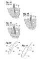
- FIG. 1shows a section of skin 20 containing a hair follicle 22 with a hair 24 disposed therein, wherein a tubular harvesting punch 26 contacts the surface of the skin.
- the punch 26contacts the skin at an angle with respect to the skin's surface over the location at which the hair 24 emerges from the skin.
- a sharp end of the punch 26penetrates the skin and advances to a depth D of between about 0.05-0.5 millimeters.
- the surgeonangles the punch 26 to an angle along the same axis as the hair growth, and further advances the punch into the dermis to a second depth D 2 of 2-7 millimeters.
- the present inventionprovides a number of solutions to deficiencies in the prior art and includes various features for increasing the yield of usable harvested biological specimens for instance a follicular unit, a skin sample, a tissue sample, or a biopsy unit.
- the inventionprovides tools that effectively penetrate tissue and remove and retain biological units therein without damaging them.
- One particularly useful application for the tools described hereinis in the area of hair harvesting and transplantation, which requires the removal of countless follicular units.
- the toolscan be manually operated or incorporated into an automated system, including robotic system.
- One aspect of the inventionis a biological tissue removal tool comprising an inner elongated body which has a lumen sized to receive a biological unit and a distal tip configured to penetrate a body surface, and an outer elongated body axially movable over the inner elongated body and having a retention member.
- the retention membermoves between a retracted position and a retention position depending upon the relative axial positions of the respective elongated bodies.
- a biological tissue removal toolcomprising an elongated body and at least one movable retention member.
- the elongated bodyhas a lumen sized to receive a biological unit and a distal end with a distal tip configured to penetrate a body surface.
- At least a portion of the retention memberis axially movable over the elongated body and the retention member is radially movable between a retracted position and a retention position, such that in the retention position at least a distal tip of the retention member extends beyond the distal tip of the elongated body and converges.
- a biological tissue removal toolcomprising an elongated body which has a lumen sized to receive a biological unit, a distal end with a distal tip configured to penetrate tissue.
- a retention memberis axially movable with respect to the elongated body and radially movable from a retracted position to a retention position. In the retraction position the retention member is substantially disposed within the elongated body, and in the retention position at least a portion of the retention member extends beyond the distal tip of the elongated body.
- the elongated bodyfurther comprises a structure configured to guide at least a portion of a retention member to converge.
- the biological unitis a follicular unit and the removal tools are hair harvesting tools.
- the toolis configured for use in a robotic hair harvesting system.
- any of the retention features of the removal tool of the present inventioncan be incorporated into a single tube or cannula, or it could form a part of an inner or outer cannula of a concentric tubes removal tool.
- the tools of the inventionmay be used for removal of biological units, including hair harvesting and/or transplantation.
- various combinations of featurescan be incorporated into a manual, semi-automatic, or fully automated system, including a robotic system. In short, unless stated otherwise, any combination of features described herein are contemplated.
- FIGS. 1A-1Cshow a section of skin containing a hair follicle in contact with a portion of a tool of the prior art
- FIG. 2Ashows the outline of a biological unit removed from a body surface by a harvesting tool advanced at an angle to the surface, while FIG. 2B shows the same biological unit and the resulting hair transection;
- FIGS. 3A-3Fillustrate a sequence of steps of operation of an exemplary biological unit removal tool of the present invention in the process of removing a follicular unit from the body surface;
- FIGS. 4A-4Care elevational and sectional views of an exemplary outer tube having a constrictive retention member of the biological unit removal tool of the FIG. 3A-3F ;
- FIGS. 5A and 5Bare side and longitudinal sectional views, respectively, of another exemplary embodiment of the biological unit removal tool of the application having a movable retention member in the form of outer tines in a retracted or an undeployed state;
- FIGS. 6A and 6Bare side and longitudinal sectional views, respectively, of the biological unit removal tool of FIGS. 5A and 5B in a retentive or deployed state;
- FIGS. 7A-7Eare various alternative views of the biological unit removal tool similar to one in FIGS. 5A and 5B ;
- FIGS. 8A-8Care several end views of the biological unit removal tool with the movable retention member of the invention, e.g. tines, showing a progression between the retracted and retentive states;
- FIGS. 9A-9Bare side and longitudinal sectional views, respectively, of a another exemplary embodiment of the biological unit removal tool of the invention having movable tines and a protective outer sheath;
- FIGS. 10A-10Bare side and longitudinal sectional views, respectively, of an exemplary manually-operated device for controlling the various biological unit removal tools of the invention
- FIGS. 11A-11Care exploded and assembled perspective views of a semi-automated handpiece or tool for controlling the various biological unit removal tools of the invention
- FIGS. 12A-12Bare side and longitudinal sectional views, respectively, of an exemplary biological unit removal tool in accordance with the invention that can be incorporated into a more automated system;
- FIGS. 13A-13Care longitudinal sectional views of three stages of operation of an embodiment according to another aspect of the present invention directed to a concentric tube concept for the biological unit removal tools;
- FIGS. 14A and 14Bare side and end sectional views, respectively, or a another exemplary embodiment of a biological unit removal tool of the invention having a movable retention member in the form of a plurality of wires shown in a retracted or undeployed state;
- FIGS. 15A and 15Bare side and longitudinal sectional views, respectively, of yet another exemplary embodiment of the biological unit removal tool of the invention having a movable retention member in the form of inner tines in a retracted or undeployed state;
- FIGS. 16A and 16Bare side and longitudinal sectional views, respectively, of the biological unit removal tool of FIGS. 15A and 15B in a retentive state;
- FIG. 17is an elevational view of one embodiment of a biological unit removal tool incorporated into an exemplary substantially automated system.
- FIGS. 18A and 18Bare perspective views of yet another embodiment of the biological unit removal tool incorporated in the exemplary robotically-operated system for hair removal and implantation.
- FIG. 2Ashows the outline of a typical biological unit 30 removed from a body surface by a tubular harvesting cannula (not shown) advanced at an angle to the surface.
- the cannulagenerally removes a tissue plug 32 , preferably centered in the example shown around a follicular unit having a bulb 34 and shaft 36 .
- a tissue plug 32preferably centered in the example shown around a follicular unit having a bulb 34 and shaft 36 .
- an undesirable lateral flap 38 of skin in the direction that the cannula is angledmay result.
- This appendage or flap 38occurs more often in high-speed punching using a harvesting cannula or needle and low angles of incidence from the body surface, such as between 15-45°.
- the flap 38may interfere with movement of the biological unit 30 through the harvesting tool, its removal from the body surface and its retention in the removal tool.
- FIG. 2Bshows an additional problem associated with the sliding of the cannula before a complete penetration of the skin while being advanced at an angle which results again in the creation of the flap and also in biological unit 30 being transected along the shaft 36 .
- the devices and methods of the present inventionare useful in manual procedures and systems, as well as in automated procedures and system.
- the tools of the present inventioncould be used with the robotically-assisted systems and procedures.
- the adverb “automatically” when referring to use of a particular component of a system or a particular step in a processmeans that such step is accomplished autonomously, i.e., without real-time manual assistance.
- toolrefers to any number of tools or end effectors that are capable of removing or harvesting various biological tissues, for example, follicular units (“FUs”) from a body surface.
- FUsfollicular units
- the tools of the present inventionmay be useful for removing biological units other than FUs from a body surface.
- a body surfacecan be attached to the body or may be a flap of skin or body tissue removed from the body.
- Such toolsmay have many different forms and configurations.
- the toolcomprises a hollow tubular shaft and thus may be labeled, for example, a cannula, a needle, or a punch.
- removal toolsfor example, punches, coring devices, cutting and/or trimming devices, needles
- tissuee.g., hair follicle
- the terms “coupled,” or “attached,” or “connected,” or “mounted” as used herein,may mean directly or indirectly coupled, attached, integrated, or mounted through one or more intervening components.
- follicular unit harvesting cannulasor tools
- follicular unit harvesting cannulasor tools
- each harvesting cannula designmay have certain benefits (e.g., superior retraction and retention of follicular units, less trauma to the surrounding skin and tissue), or drawbacks (e.g., complex design and/or operation, higher manufacturing costs, increased trauma), relative to the other embodiments.
- selection of a particular harvesting cannula distal end designwill depend on the particular performance criteria sought to be achieved.
- Bio unitsinclude discrete units used in cosmetic, diagnostic, and dermatological procedures, for example, various tissues, including that extracted for biopsies or grafting, fat units, skin units, etc.
- Examples of the biological units particularly useful with the present inventionare hair grafts, or follicles, or “follicular unit(s).”
- Other biological unitsmay be tissue used for diagnosis of cancer, such as from the areas of the breast, liver, prostate, colon and small bowel, or lungs. Other tissue examples where biopsies are performed include bone, heart and brain tissue.
- “biological unit”may alternatively be referred to as “biopsy sample,” “biopsy specimen,” “biological tissue sample,” or “biological tissue specimen.”
- biological unitsencompasses a number of things, though the present invention is particularly useful in hair harvesting, to provide devices and methods for harvesting follicular units (FUs).
- FUsfollicular units
- the term follicular units (or FUs)will be used herein simply as an example for purposes of describing some embodiments of the present invention with the understanding that it represents more broadly biological units.
- the removal tool of the present inventionis designed to help retain a biological unit within the tool without damaging it. That is, the removal tool penetrates a body surface, causes a biological unit to enter a lumen therein, and then removes it. It is important that the biological unit goes with or is retained within the removal tool as it is retracted from the body surface. Often, however, the biological unit remains connected in some manner to the tissue that had been surrounding it. For example, a follicular unit may remain attached to the body surface by surrounding connective tissue, even if a vacuum is used in the tool lumen. The surrounding connective tissue tends to pull back the follicular unit from the removal tool which sometimes results either in tearing the follicular unit apart, or simply not retaining it in the removal tool.
- biological specimens that are taken for cancer biopsies, etc.share similar issues with follicular units. That is, it may be important to keep a biopsy specimen intact and not damaged or separated because it may be desirable to see all of the layers of the specimen in exact original order and form to determine an exact location of the cancerous portion (or other problem).
- the present inventionthus provides a retention solution that helps pull biological units free from the surrounding tissue.
- the present inventionprovides an improved biological unit removal tool that solves certain problems associated with some prior art designs that have one or two sharp proximally-oriented barbs to retain tissue specimens with a tool. Such barbs tend to either destroy or damage the specimen, and may in any event have insufficient retention structure to hold the biological unit within the tool upon removal.
- the present inventionprovides a retention structure that is effective in retaining the biological unit within the lumen of the tool without damaging the biological unit.
- Various features for improving retention, reducing a flap and transection ratesmay be incorporated in a single elongated body that is used to penetrate tissue and remove the biological unit. Such features enable a removal tool to be sharp to cut through the epidermis and dermis, and at the same time dull to pass through fatty tissue that surrounds a biological unit such as a follicular unit.
- Another approach in solving the problems associated with certain prior art devicesis to separate the functions of the removal tool into two different tubes that are utilized in concert, for example a dual-needle or concentric tube can be utilized. It should be understood that various features described herein may be combined with the tool in a similar manner, unless there is some mutually exclusivity between the tools.
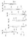
- FIGS. 3A-3Fillustrate the first example of one embodiment of the invention, demonstrating a sequence wherein the removal tool 200 removes a follicular unit FU from below a body surface, denoted by a skin plane 210 , of a donor area.
- the configuration used to illustrate the sequence shown in FIGS. 3A-3Fis representative of one configuration that can be used, but not limited to that shown.
- a concentric tube biological unit removal tool 200comprises an outer elongated body 202 concentrically disposed to slide over an inner elongated body 204 .
- the two elongated bodies 202 , 204are desirably tubular both having cylindrical inner lumens so that they may freely rotate with respect to each other. Alternatively, the cross-section may be other than tubular which might preclude relative rotation.
- the terms elongated bodies and tubeswill hereafter be used interchangeably.
- the inner elongated body 204includes a distal cutting tip 206 .
- Distal tips 206 of varying configurationscan be utilized. Certain distal tip designs help to minimize damage to the harvested biological unit and to improve the quality of the harvested specimen. Examples of possible designs can be found in U.S. Patent Publication Number US2008/0234698.
- the distal tip 206may define a non-circular periphery, be defined by a series of alternating cutting and relief segments which repeat a pattern of constant or varying spacing, or resemble a “crown” shape.
- some or all of the relief segmentsmay be offset axially or proximally from the cutting segments.
- the shapes of the cutting segments and relief segmentsmay take a variety of forms.
- the provision of alternating relatively sharp or cutting segments with relatively dull or relief segmentsreduce the chance of transection of hair shafts during follicular unit removal.
- the relative sizes and shapes of the cutting segments and relief segmentsdetermine the character and magnitude of cutting versus bluntly dissecting. For example, in some instances a tool that has less cutting ability may be required, such as when harvesting follicular units from a subject that has relatively thin hair follicles which transect more easily, and vice versa.
- the cutting tip 206may have both cutting (e.g., sharp) and dissecting (e.g., blunt) segments around a periphery thereof. As explained above, this arrangement helps prevent transection of biological units, especially follicular units, as the inner tube 204 descends through tissue.
- the outer elongated body 202also includes a distal tip 208 , though it is preferably blunt so as to be capable of dissection of tissue but relatively incapable of cutting through follicular units or the like.
- FIG. 3Ashows the tool 200 positioned over a skin plane 210 with the follicular unit FU embedded below the skin plane.
- the inner tube 204is seen advanced a predetermined distance beyond the distal tip 208 of the outer tube 202 .
- FIG. 3Billustrates the tool 200 after having been displaced such that a majority of the exposed portion of the inner tube 204 has penetrated the skin plane 210 such that the distal tip 206 extends past the follicular unit FU.
- suction within an inner lumen of the inner tube 204helps begin removal of the follicular unit FU.
- FIG. 3Cillustrates the next step in which the outer tube 202 advances axially over the inner tube 204 .
- the distal tip 208 of the outer tube 202extends as far as the distal tip 206 of the inner tube 204 , or at least extends past the follicular unit.
- a stop mechanism between the two tubes 202 , 204may be provided to facilitate the co-extension therebetween.
- FIG. 3Dillustrates proximal retraction of the inner tube 204 within the outer tube 202 .
- the outer tube 202features a biological unit retention mechanism or member 220 that is actuated upon retraction of the inner tube 204 .
- retention mechanism or retention memberwill hereafter be used interchangeably.
- the retention member 220as described in more detail below with respect to FIGS. 4A-4C , includes a plurality of radially movable members 222 that are biased inwardly.
- the movable members 222Prior to retraction of the inner tube 204 , the movable members 222 remain in outer retracted position, and upon removal of the inner tube the movable members constrict inward around the follicular unit FU, as seen in FIG. 3D . In this position, the retention member 220 is said to be in its retention position.
- the movable members 222are spaced circumferentially around the wall of the outer tube 202 and constrict inward to define an hourglass shape which includes a reduced diameter neck 224 close to the distal tip 208 .
- the reduced diameter neck 224is located distal to the follicular unit FU so as to retain or capture it within the lumen of the outer tube 202 .
- the reduced diameter neck 224may be located somewhere along the length of the follicular unit FU as long as it non-traumatically envelops or “hugs” the follicular unit providing the desired retention without damaging the FU.
- the entire tool 200is withdrawn from the skin plane 210 .
- the follicular unit FUis seen captured within the outer tube 202 , which remains advanced with respect to the inner tube 204 .
- the positive retention of the follicular unit FU in this mannerwill effectively extract the follicular unit from any surrounding tissue under the skin plane 210 .
- FIG. 3Fillustrates a subsequent step in which the outer tube 202 has been retracted in the proximal direction with respect to the inner tube 204 .
- the inner tube 204could be advanced distally with respect to the outer tube 202 . This relative movement causes the movable members 222 outward to their retracted position.
- the inner tube 204receives the follicular unit FU within its lumen as it advances through the outer tube 202 .
- the tool 200captures the follicular unit first within the inner tube 204 , transfers it into the outer tube 202 , and then transfers it back to the inner tube 204 .
- FIGS. 4A-4Cillustrates an exemplary alternative outer tube 202 of the present invention shown in a relaxed or retentive configuration in which the aforementioned movable members 222 are displaced radially inward.
- the outer tube 204includes a proximal end 230 and the aforementioned distal tip 208 .
- a proximal, preferably solid, tubular portion 232extends approximately half the length of the tube 204 .
- the distal tip 208comprises a generally tubular ring section 234 preferably having the same diameter as the proximal tubular portion 232 .
- the movable members 222extend and define the cross-sectional shape of the outer tube 202 .
- Each of the movable members 222may be formed from the wall of the outer tube 202 , preferably by laser cutting of a tubular blank.
- the outer tube 202may be made of the highly elastic material such as Nitinol, although certain elastic polymers may also be suitable.
- the movable members 222are elongated in an axial direction and separated from each other by elongated slots 240 , as seen in FIG. 4C .
- each of the slots 240is relatively narrow, extending axially and terminating at both ends in a pair of enlarged windows 242 .
- the enlarged windows 242may be circular, as illustrated, such that the slots 240 resemble barbells.
- FIGS. 4A-4Cillustrate a configuration in which there are three evenly spaced slots 240 , of identical length, width and shape, with identical windows 242 . It will be appreciated that the movable members may be formed with differing numbers of slots 240 , unevenly spaced, and of varying lengths, width and shape combinations.
- Nitinolis a material that can be designed so that above certain stresses it becomes super-elastic.
- the relaxed or retentive configuration with the retention member 220 constricted as in FIG. 3Dmay be the pre-biased or unstressed shape (which is achieved through a heat-setting or thermal process, as known in the art), and the stressed shape is when the presence of the inner tube 202 expands the retention member 220 , thus stressing it above a certain limit so it becomes superelastic (however, the strain levels may not require that the material needs to enter superelastic range).
- the retention member 220again constricts inward and resumes its relaxed shape with no plastic deformation.
- Such material propertyis sometimes known as superelasticity, or stress-induced martensitic transformation.
- each movable member 222consists of a proximal trapezoidal segment 244 , a central rectangular segment 246 , and a distal generally trapezoidal segment 248 .
- bend linessuch as the one labeled at 250 at the proximal end of the visible movable member 222 .
- the proximal and distal most bend lines 250preferably lie in planes that bisect the enlarged windows 242 so that the material cross-section of those points is reduced.
- the intermediate bend lines 250are located in the area of the reduced diameter neck 224 .
- the configuration of the outer tube 204 and having movable members 222is such that the bend lines 250 are located at points where the area moment of inertia of the wall of the tube is low relative to surrounding sections, thus facilitating inward and outward movement of the members 222 by flexion about bend lines.
- the distal endfurther includes short slots 260 that extend from the distal tip 208 of the outer tube 204 to enlarged windows 262 in the middle of the distal segments 248 of each movable member 222 . These distal slots 260 further facilitate flexion of the movable members 222 .
- the distal end of the outer tube 204describes nearly a continuous circular periphery, except for the distal slots 260 .
- the particular design of the outer tube 204 comprising the movable numbers 222is exemplary only, and a number of different configurations are contemplated.
- the biological unit retention function of the movable members 222could conceivably be accomplished by using only one movable member, or more than three.
- there are movable members disposed substantially around the circumference of the outer tube 204meaning at least three of them.
- the movable members 222are configured to have proximal and distal ends that are solidly connected to the nominal tubular wall of the outer tube 204 , with the middle portions flexing inward, alternative embodiments could have just the proximal ends connected to the outer tube, while the distal ends cantilever inward.
- the outer tube 204may be made of a highly elastic material that stretches and not have any slots at all, such as a solid tube with the neck 224 .
- Alternative movable member 222 configurationscan be selected to better suit the type of biological unit being removed, the nature of the surrounding tissue, or the nature of the removal process.
- member configurationsthat are tongue- or petal-like, multi-pronged, prongs equi-distributed, or prongs of varied distributions may be utilized, the prongs being of various lengths, shapes, thicknesses and surface finishes.
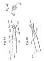
- FIGS. 5A and 5Bare side and longitudinal sectional views, respectively, of a second exemplary embodiment of a biological unit removal tool 350 according to the invention having a movable retention member in the form of outer tines or blades 352 in an undeployed or retracted state
- FIGS. 6A and 6Bshow the removal tool in a deployed or retentive state
- FIGS. 7A-7Eshow further views of the biological unit removal tool similar to those of FIGS. 5A and 5B
- FIGS. 8A-8Care several end views showing a progression between the retracted and retention positions.
- the outer tines or blades 352are deformable and extend from an outer tube 354 .
- the function of the blades 352is similar to the embodiment shown in FIGS. 3-4 but with the blades at least partially located on the outer tube 354 and guided through slots, channels or openings 355 located at the distal end 356 of an inner tube 358 .
- One or more slots, channels or openings 355may be located anywhere proximally to the distal tip. In some embodiments, they may be in close proximity to the distal tip, in other embodiments they may be positioned further from the distal tip along the length of the inner tube.
- FIG. 7Dis a view looking into the distal end 356 of the inner tube 358 . It can be seen that at least a portion of the retention member (in this case the distal ends of the tines 352 ) extend beyond the distal tip of the inner tube 358 and converge.
- irrigationfor example in the form of a saline fluid, can be injected between the outer tube 354 and the inner tube 358 so as facilitate the capture of the follicular unit, as well as, to minimize the accumulation of blood, tissue, and debris in between the tube members during prolonged procedures by constantly flushing the region between the tube members.
- FIGS. 8A-8Care several end views of the biological unit removal tool with the blades or tines 352 , showing a progression between the retracted ( FIG. 8A ) and retentive states ( FIG. 8C ).
- FIG. 8Ait can be seen that substantially no portion of the tines 352 projects across the lumen.
- FIG. 8Bthe tines 352 are in the process of leaving their retracted position, and project partially across the lumen.
- FIG. 8Cthe tines project both into and across the lumen.
- FIG. 7Cwhich once again is a view looking into the distal end 356 of the inner tube 358 .
- the tips of the tinesmay be located at the opening of the slot for easy re-entry.
- the position of the tines relative to the slot and the shape of the tines (and/or slot)can be configured, such that even during insertion into tissue or with inward deflection of the tines, the tips of the tines remain substantially removed from the inner lumen, so as not to project into the lumen.
- the diameter of the inner tube 358 behind the tip portion 356may have a reduced diameter (which may be incorporated into any of the embodiments) to ensure a low profile.
- the tinesalso desirably lie in tracts that are parallel to the long axis and further reduce the profile so that the tines do not extend much beyond the outer diameter of the tip. Three exemplary tines are shown in FIGS. 5A- and 5 B, but there could be other numbers of tines employed in various embodiments, for example, two, four, five or more.
- the tines 352may be configured as wires, filaments, fingers, or paddle-shaped, for example.
- any potential trauma that may be experienced by the biological unit and/or the surrounding tissuecan be reduced by providing tines or blades 352 that are made of Nitinol, titanium, Elgiloy, cobalt chromium, Teflon, silicon, rubber, polymer, plastic or any other materials that are non-traumatic and/or reduce the possibility of damage to the biological unit and/or the surrounding tissue.
- providing blades 352 having at least tip portions 360 that are made of a material different to the remainder of the material of the blade 352can achieve this purpose.
- removal or reduction of any sharp edges or corners at, near or around the slot, or any other portion of the devicecan also be utilized to minimize damage to the biological unit.
- FIG. 7Eshow another aspect of the invention, in which the tip portions 360 of the blades 352 are adapted such that when they coapt or converge, they do not meet substantially along the longitudinal axis of the lumen of the inner tube 358 (in other words, they do not completely close), but stop short of doing that. Therefore, a small gap 362 is created, thus providing another means by which the biological unit and/or the surrounding tissue can be less traumatized during the removal process, especially in those embodiments where the blades or tines 352 converge somewhere along the length of the follicular unit to hold it tight. Trauma experienced by the biological unit and/or the surrounding tissue can be further reduced by adapting the tip portion 360 to minimize such trauma.
- Such adaptationsincluding, for example, modification to the shape or finish to the tip portion 360 of the blade 352 .
- Adaptationsinclude but are not limited to tip portions that comprise any one or more of non-knife-like, blunt or rounded edges, jagged edges, tapers or other such gradual transitions, crown-like shaping, and roughened finishes.
- These non-traumatic and non-completely converging tip portionsmay be incorporated into any of the embodiments of the retention members described herein in reference to various Figures.
- the blade tips 360may extend to form an elongated section, taking the form of flattened blades for example.
- the elongated sections of the blade tips 360extend in a direction that is longitudinal to the lumen formed in the inner tube 358 , and coapt such that they physically retain the biological unit along a length of the elongated sections.
- FIGS. 9A-9Bare side and longitudinal sectional views, respectively, of yet another embodiment of the biological unit removal tool 370 of the present application having a movable tube with blades or tines (not shown) and a protective outer sheath 374 .
- the separate outer sheath 374fits over an inner tube member 375 which has window features 376 cut, typically by laser, EDM, or conventional machining.
- the outer sheath 374has internal longitudinal channels 378 which accommodate the tines and help guide the tines within the windows 376 . (Black lines 380 indicate the path for the tines).
- One advantage of this embodiment of the inventionis that it protects the tines and minimizes possible deflection or disengagement with the windows 376 because of an interaction with the tissue.
- the windows of the inner tube 375may also have tabular features within the tube to help guide the tine tip (not shown), especially if the outer sheath is made from polymer, as repeated cycling may damage the polymer portion that interacts with the tine tip.
- the sheath lengthcan cover the area just at the tip of the inner tube 375 , or it could be longer and extend along any portion and up to the full length of the inner tube.
- a polymer materialfor example a heat-shrinkable polymer polyester, can be placed on the outside of the tines of FIG. 5 and FIG.
- a section of the tip portion 356may be formed from a polymer material, either through an overmolding process, by reflowing a covering material through a thermal process, or by creating the shape through the application, shaping, and/or forming of a material, which can be polymer, metal or a combination of the two.
- FIGS. 10A-10Bare side and longitudinal sectional views, respectively, of an exemplary manual handpiece 390 for controlling the various biological unit removal tools of the present application.
- the handpiececan be used to actuate/mechanize the tined tip devices previously described.
- a return spring 394causes the slider 392 to return to its original position and “part” the outer tines in the slots or windows and out of the lumen.
- the “handle” portioncan be made from a variety of materials, including but not limited to polymer, aluminum, etc.
- FIGS. 11A-11Care exploded and assembled perspective views of a semi-automated handpiece 400 for controlling the various biological unit removal tools of the present application.
- FIG. 11Ais an expanded view of a mechanized tool 400 using an electric motor with a gear reduction head to provide, for example, a 400 rpm rotary speed to provide rotary control of the coring tube (whichever of the inner or outer tubes ends up containing the biological or follicular unit).
- Two gearsoffset the drive mechanism so that a cartridge 402 can enter and exit the hollow tapered spindle.
- the cartridge 402 in this examplemay be similar to the handpiece 390 described above, or may be another of the concentric tubular assemblies described herein.
- FIG. 11Bis a collapsed view showing the cartridge 402 engaged into a hollow spindle 404
- FIG. 11Cis a view showing the handle 400 outer body surface.
- the cartridgecan be inserted into the hollow tapered spindle of the tool and locked in place either with a threaded portion or with a twist-and-lock feature (not shown).
- the inner tubular memberpasses all the way through the tool and exits the rear where it may interface to a vacuum collection system.
- pneumatic actuators shownthat act on a collar feature that then pushes on the external tabs of the cartridge.
- the mechanismmay be, for example, a scaled-down version of the manual device of FIGS. 10A-10B
- FIGS. 12A-12Bare side and longitudinal sectional views, respectively, of an exemplary biological unit removal tool or cartridge 410 in accordance with the present application that can be incorporated into a more fully automated system.
- the cartridge 410includes a similar actuation mechanism as the manual device, but now the slider has two outwardly extending tabs 412 upon which a pneumatic collar (not shown) may act to provide the linear distal displacement.
- This assemblymay be incorporated into semi- or fully-automated systems, such as described below, and may also be coupled with the mechanized handpiece 400 of FIGS. 11A-11C .
- the various biological unit removal toolsare operated by a technician or a physician to remove biological units, such as follicular units during a hair harvesting or hair transplantation procedure.
- the technicianfirst pierces or penetrates the skin surface with the coring needle or tube, which may be simultaneously rotated. At a predetermined depth, such as between 1-5 mm for follicular units, the technician may halt further rotation of the coring needle. The technician then activates the particular retention member (e.g., tines, blades, wires, petals, etc., as described above) to prevent the biological unit from exiting the lumen of the coring needle.
- the particular retention membere.g., tines, blades, wires, petals, etc., as described above
- the coring needlemay then resume spinning, if able, to help sever the biological unit from its tissue bed. Withdrawal or retraction of the entire removal tool completes the process, with the biological unit remaining in the needle lumen for later explusion from the distal end, possibly with the aid of compressed air or the like, or proximally through the needle shaft, possibly with the aid of a vacuum source or the like. During certain applications, it is possible to continue rotation or spinning of the coring needle through the whole process.
- FIGS. 13A-Cdepict the distal end portion of an alternate embodiment of a tool assembly 520 for harvesting biological units 522 from a body surface 524 .
- the tool assembly 520includes a pair of coaxially disposed cannulas 526 and 528 that are moveable relative to one another.
- a collet 530holds (and moves) an outer cannula 526 having a blunt distal end opening 532 into the skin surface 524 .
- an inner cannula 528 having a sharpened distal end 534is thrust at high speed through the inner lumen of the outer cannula 526 to pierce the skin surface 524 to a depth of approximately 1 to 2 mm.
- Both cannulas 526 and 528are then withdrawn together from the skin surface 524 .
- the removal toolhas two concentric needles or tubes.
- An inside needleis sharp or semi-sharp, and an outside needle is relatively dull or less able to cut through tissue than the inside needle.
- the outside needlemoves slowly down around the inner needle, whereas the inside needle makes a sudden and rapid punching motion to form a 0.5-2.0 mm deep circular incision.
- the outside needlecan then follow the inside needle into the circular cut made by the inside needle and continue through deeper fatty tissue to a depth of 5-8 mm.
- the relatively dull edge of the outside needlewill guide any hair follicles into both the inner and outer needles instead of transecting them.
- An exemplary embodiment implemented with respect to the embodiment of FIGS. 13A-13Cmay include a rod or piston 540 connected to a proximal end of the outer tube 526 and movable within a plenum chamber 542 . Alternating positive and negative pressure within the plenum chamber 542 therefore advances and retracts, respectively, the outer tube 526 .
- the inner tube 528may be similarly actuated, or may be connected to a mechanical stepper motor or the like (not shown).
- FIG. 13Ashows the outer tube 526 disposed above the skin surface 524 and positioned over the hair of a follicular unit 522 .
- the inner tube 528is then advanced rapidly within the outer tube 526 such that the sharp distal end 534 incises a circular cut in the skin surface 524 .
- the outer tube 526follows over the inner tube 528 and continues deeper below the skin surface 524 to surround the follicular unit 522 .
- retention meanssuch as various retention members described above
- within the inner or outer tubesmay take effect or be actuated, and the assembly pulled free of the skin surface 524 such that the follicular unit 522 is captured therein.
- the retention membermay be incorporated into the inner, or outer cannulas, or both. Suction within a lumen 544 of the inner tube 528 may be used to further transfer the follicular unit 522 in a proximal direction.
- the concentric tube embodiment described aboverelies on the formation of a circular incision made by the sharp inner tube after which the less sharp outer tube follows into the tissue.
- One undesirable possibilityis the enlargement or destruction of the clean circular incision by the blunt outer tube.
- the outer tubemay be rotated while the descending into the incision to reduce the chance of catching on the incision from direct linear movement.
- a small annular space between the inner and outer tubesmay be designed so that the outer tube rotates slightly off the axis of the inner tube so as to wobble or be mis-aligned with respect thereto.
- both tubesmight be caused to rotate off-center from their own axes and wobble.
- the wobbling from one or both tubesmay allow the outside tube to spiral into the opening created by the inside tube.
- the removal tool and corresponding process described with reference to FIGS. 13A-Cmay be substantially automated, and it is especially fitted for use with robotic or computer-controlled systems.
- FIGS. 14 A and 14 Bare side and cross-sectional views, respectively, of another exemplary embodiment of the biological unit removal tool of the invention having a movable retention member in the form of a plurality of movable wires 558 .
- the figuresillustrate the biological unit removal tool in its retracted position, in which substantially no portion of the movable member 558 projects into or across the lumen 552 .
- this particular configurationemploys the use of eight evenly circumferentially-distributed wire fingers, though it will be apparent to the reader that any number of, and a varied distribution of wire fingers may be utilized.
- the exemplary removal tool 550has a guide 554 that resides on the outer wall of the member 552 that defines a lumen, and a protective outer sheath 556 .
- the guide 554has an internal structure 566 such as a channel, or guide which helps guide the movable member 558 in the form of a Nitinol wire finger, for example (though certain other materials that are elastic in nature may also be suitable, such as titanium, Elgiloy, cobalt chromium, Teflon, silicon rubber, polymer or other plastics) through an opening 568 between the guide 554 and the outer sheath 556 .
- the outer sheath 556may also assist in this guiding process.
- the guide 554 and protective outer sheath 556also house an actuator 560 which moves distal/proximal relative to the lumen and provides a means to control movement of the movable member 558 in and out of the opening 568 .
- actuator 560is also configured such that it assists the movable member 558 in maintaining its original shape in the radial direction even though it is continually being moved in a longitudinal direction substantially parallel to the longitudinal axis of the lumen 552 . Provision of such assistance during both the retention and the retraction process reduces distortion of the wire finger in the radial direction with respect to the lumen 552 .
- the actuator 560employs the combination of an o-ring 564 and a groove 562 which is shaped to accommodate the o-ring 564 between the groove 562 and the outer sheath 556 , the combination keeping the wire in place.
- the wire fingeris additionally solidly affixed to the actuator 560 at the proximal end thereof.
- the actuator 560is moved to advance in the distal direction relative to the lumen, cause the movable member 558 to exit the opening 568 , and converge with other movable members 558 in the retention position, in which the movable members 558 assist in retention of a biological unit.
- the actuatoradvances the movable members such that at least a portion of the movable members extends beyond the distal end of the lumen and converges.
- the movable member 558is pre-biased in the retention position, and when retracted back through the opening 568 is in a more stressed state.
- the movable membersare made with a material that permits repeated flexing and outward without fatigue, or exhibits superelastic or stress-induced martenistic transformation properties.
- the opening 568is adapted to guide the movable member in the desired direction, such guiding provided by a ridge, step or other such guiding feature.
- this removal toolcan be actuated manually, or be incorporated into a semi- or fully-automated system.
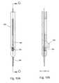
- FIGS. 15A and 15Bare side and longitudinal sectional views, respectively, of yet another exemplary embodiment of the biological unit removal tool of the invention having a movable retention member in the form of inner tines in a retracted or undeployed state, and FIGS. 16A and 16B show the removal tool in a retention or deployed state.
- the exemplary removal tool 640 of FIGS. 15-16has an outer tube or outer member 642 defining a lumen, and an inner tube or inner member 644 with a plurality of movable members or deformable tines 646 mounted on the inner tube.
- the deformable tines 646are flush with the inner diameter of the outer tube 642 and mounted to the distal end of the inner tube 644 , which is allowed to move proximal/distal relative to the distal tip 643 of the outer tube.
- the distal tip 643has a structure 645 that influences or guides the deformable tines to converge.
- the structure 645can take the form of an inner ridge that guides the tines inward as the inner tube is advanced distally such that the tines converge.
- the structuremay take the form of a taper, a step, an incline or any other form that guides the deformable tines to coapt.
- the deformable tinesextend beyond the distal tip of the outer elongated member 642 .
- the inner tube with tinesmay be made of various materials, including shape memory materials, for example, Nitinol, or Elgiloy, or cobalt chromium, or similar material which accommodates repetitive bending without fatigue (or with more tolerant fatigue properties), if desired, at the base of the tines.
- the movable retention membersneed not be in the form of tines, but may be configured as thin wires, filaments, or paddle shaped structures for example, or varying shapes and surface finishes, and of various circumferential distributions.
- the exemplary embodiment of the present inventionmay be used in the manual hand-held removal tools, it could also be beneficially incorporated into automated, or semi-automated systems and devices. Specifically, it could be implemented in the robotically-assisted systems and devices, for example, by being connected to the moveable robotic arm. Some exemplary embodiments of such automated systems are described below in reference to FIGS. 17 and 18 A- 18 B.
- FIG. 17is an elevational view of one embodiment of a concentric tube biological unit removal tool incorporated into an exemplary substantially automated system, such as robotic system.
- the removal tool assemblyis carried on an automated (e.g., robotic) arm, so that movement of the removal tool relative to the body surface may be performed by movement of the robotic arm relative to the body surface, movement of the removal tool relative to the automated arm, or a combination of each.
- the assembly of FIG. 17may be modified to incorporate the exemplary outer elongated body 204 of FIGS. 4A-4C , and caused to operate as seen in FIGS. 3A-3F .
- FIG. 17shows a concentric tube embodiment in which an inner tube 700 slides inside an outer tube 702 .
- a source of reduced pressurecommunicates with a lumen 704 of the inner needle 700 to create a pressure differential therein for moving biological units through the lumen in a proximal direction.
- the inner needlemay be held at the end of a linearly movable rod 706 , while the outer needle is held in a collet 708 and may be rotated or oscillated relative to the inner tube through a spindle 710 on the end of which the collet mounts.
- a spring 712acts in a distal direction on a sleeve 714 to maintain the jaws of the collet 708 closed.
- the inner tube 700has a distal tip that is sharp, or at least that has cutting segments thereon.
- the inner tube 700translates at a relatively high velocity of between 1-3 m/s, and penetrates the skin (i.e., body surface) to a depth of between 0.25-3.0 mm.
- the inner tube 700remains under the surface while the outer tube 702 follows.
- the outer tube 702is desirably relatively dull compared to the inner tube 700 , and enters the skin through the incision that the inner tube 700 created.
- the outer tube 702stretches the skin to make the incision somewhat bigger, and enters at a slower velocity, for example, of between 1.0-25.0 mm/s.
- the outer tube 702may be rotated or oscillated during its advance. After the outer tube 702 enters the skin, the inner tube 700 may move in concert with the outer tube, remain stationary, or retract as the outer tube continues farther into the skin. Likewise, both tubes 700 , 702 may retract from the skin simultaneously, or separately, and may retract at the same or different velocities.
- suctionis desirably applied within the inner tube lumen 704 to aid in biological unit retention. In addition, suction may be applied between the inner and outer tubes 700 , 702 , and fluids or gas may be supplied between the tubes to aid in retention.
- FIGS. 18A and 18Bare perspective views of yet another embodiment of the biological unit removal tool 750 incorporated in an exemplary robotically-operated system 752 for hair removal and implantation.
- the assembly of FIGS. 18A-18Bmay be modified to incorporate the exemplary outer elongated body 204 of FIGS. 4A-4C , and caused to operate as seen in FIGS. 3A-3F .
- a bank of LEDs 754illuminates a body surface in front of the system so that an imaging device 756 , such as a pair of cameras in the illustrated embodiment, obtains a clear picture for transmission back to a monitor (not shown).
- an imaging device 756such as a pair of cameras in the illustrated embodiment, obtains a clear picture for transmission back to a monitor (not shown).
- Various componentsare mounted for rotation or linear translation of the removal tool 750 at the distal end of the system. Stepper motors, hydraulic cylinders, and the like may be used, and will not be described in great detail herein.
- the systemmay further incorporate a fluid (e.g., saline) delivery subsystem 760 as seen in FIG. 18B near the distal end of the removal tool.
- FIG. 18Balso shows an inner tube 770 having a crown-shaped distal tip 772 and a retention device therein 774 .
- An outer tube 776surrounds the inner tube 770 . Fluid may be delivered in a concentric space between the two tubes 770 , 776 .
- FIG. 18Aalso illustrates an exemplary subsystem for moving the inner and outer tubes 770 , 776 together and with respect to one another.
- the inner tube 770extends along an axis of the subsystem in a proximal direction and is held within a clamp 780 fixed with respect to a movable piston 782 .
- the piston 782reciprocates within a gas cylinder 784 depending on the pressure within the cylinder, which is controlled by a pneumatic subsystem that will be apparent to one of skill in the art.
- a distal end of an elongated flexible tube 786abuts a proximal end of the inner tube 770 within a clamp 780 , and defines a continuous extension of the lumen within the inner tube.
- a suctionmay be created within the inner tube 770 , which continues through the flexible tube 786 .
- the proximal end of the flexible tube 786engages a storage cartridge (not shown) for receiving and holding follicular units.
- the inner tube 770extends a significant length beyond the outer tube 776 , and therefore it should be understood that the aforementioned exemplary lengths for the removal tools applies just to the outer tube 776 .
- the outer tube 776also reciprocates with a piston 790 within a gas cylinder 792 .
- a leading end nut 794holds the outer tube 776 fixed relative to the piston 790 .
- the fluid delivery subsystem 760is located on a distal end of the nut 794 .
- a gear 796is keyed to and rotates the piston 790 , and thus the outer tube 776 .
- the inner and outer tubes 760 , 776translate coaxially with respect to one another (or in concert) and are displaced by independently controlled piston/cylinder mechanisms.
- the mechanisms for linearly displacing the two tubes 760 , 776may be linear motors or other alternatives.
- the outer tube 776rotates with respect to the inner tube 760 , and may be rotated in a constant or pulsed manner as it travels in a distal direction over the inner tube 760 and into the skin, as mentioned above.
- the subsystem shown in FIG. 18Acan, with the help of the visualization tools 754 , 756 and a computer monitoring subsystem (not shown), rapidly remove follicular units from a body surface and transfer them to a storage device.
- a storage devicethat could be incorporated into an automated system, such as robotic system, for use with the present invention, is shown and described in co-pending application Ser. No. 60/997,188 filed Sep. 29, 2007 in reference to an exemplary system for robotic hair transplantation.
- the structural parameters for the inner and outer tubes 770 , 776are desirably the same as described above for the concentric tubes 700 , 702 of FIG. 17 .
- the entire subsystem 752maneuvers into position (under the control of larger prime movers) so as to locate the distal tip 772 over a particular follicular unit to be removed.
- the visualization subsystem 754 , 756is extremely valuable in pinpointing the location and orientation of the visible hair follicle.
- the piston/cylinder combination 782 , 784then actuates to punch the inner tube 770 into the skin to a depth of up to 3 mm and at a very high velocity (for example, 1-3 m/s).
- the distal tip 772includes both sharp and dull segments so that transection of the hair follicles is minimized.
- the piston/cylinder combination 790 , 792 and gear 796translates with rotation the outer tube 776 over the inner tube 770 in a distal direction.
- the outer tube 776desirably has a relatively dull distal tip which enters the circular incision that the inner tube 770 created.
- the outer tube 776proceeds at a relatively slow velocity of 1-25 mm/s past the end of the inner tube 770 and to a depth of approximately 5-7 mm, surrounding the targeted hair follicle.
- Suctionmay be applied to the lumen of the inner tube 770 which continues through the lumen of the outer tube 776 and helps pull free the follicular unit.
- fluidmay be applied by the subsystem 760 to the space between the two tubes to further help remove the follicular unit. Retraction of the outer tube 776 , preferably in conjunction with the inner tube 770 and, also in some preferred embodiments with the help of the retention device 774 , fully removes the follicular unit from the body surface.
Landscapes
- Health & Medical Sciences (AREA)
- Life Sciences & Earth Sciences (AREA)
- Surgery (AREA)
- Engineering & Computer Science (AREA)
- Biomedical Technology (AREA)
- Medical Informatics (AREA)
- Molecular Biology (AREA)
- Heart & Thoracic Surgery (AREA)
- Animal Behavior & Ethology (AREA)
- General Health & Medical Sciences (AREA)
- Public Health (AREA)
- Veterinary Medicine (AREA)
- Nuclear Medicine, Radiotherapy & Molecular Imaging (AREA)
- Robotics (AREA)
- Pathology (AREA)
- Plastic & Reconstructive Surgery (AREA)
- Transplantation (AREA)
- Surgical Instruments (AREA)
Abstract
Description
Claims (20)
Priority Applications (1)
| Application Number | Priority Date | Filing Date | Title |
|---|---|---|---|
| US14/186,174US9017343B2 (en) | 2008-03-18 | 2014-02-21 | Biological unit removal tools with movable retention member |
Applications Claiming Priority (5)
| Application Number | Priority Date | Filing Date | Title |
|---|---|---|---|
| US3770108P | 2008-03-18 | 2008-03-18 | |
| US14709009P | 2009-01-24 | 2009-01-24 | |
| US12/403,605US8226664B2 (en) | 2008-03-18 | 2009-03-13 | Biological unit removal tools with movable retention member |
| US13/533,614US8696686B2 (en) | 2008-03-18 | 2012-06-26 | Biological unit removal tools with movable retention member |
| US14/186,174US9017343B2 (en) | 2008-03-18 | 2014-02-21 | Biological unit removal tools with movable retention member |
Related Parent Applications (1)
| Application Number | Title | Priority Date | Filing Date |
|---|---|---|---|
| US13/533,614ContinuationUS8696686B2 (en) | 2008-03-18 | 2012-06-26 | Biological unit removal tools with movable retention member |
Publications (2)
| Publication Number | Publication Date |
|---|---|
| US20140171827A1 US20140171827A1 (en) | 2014-06-19 |
| US9017343B2true US9017343B2 (en) | 2015-04-28 |
Family
ID=40622253
Family Applications (3)
| Application Number | Title | Priority Date | Filing Date |
|---|---|---|---|
| US12/403,605Active2029-10-07US8226664B2 (en) | 2008-03-18 | 2009-03-13 | Biological unit removal tools with movable retention member |
| US13/533,614Active2029-04-12US8696686B2 (en) | 2008-03-18 | 2012-06-26 | Biological unit removal tools with movable retention member |
| US14/186,174ActiveUS9017343B2 (en) | 2008-03-18 | 2014-02-21 | Biological unit removal tools with movable retention member |
Family Applications Before (2)
| Application Number | Title | Priority Date | Filing Date |
|---|---|---|---|
| US12/403,605Active2029-10-07US8226664B2 (en) | 2008-03-18 | 2009-03-13 | Biological unit removal tools with movable retention member |
| US13/533,614Active2029-04-12US8696686B2 (en) | 2008-03-18 | 2012-06-26 | Biological unit removal tools with movable retention member |
Country Status (2)
| Country | Link |
|---|---|
| US (3) | US8226664B2 (en) |
| WO (1) | WO2009117324A1 (en) |
Cited By (14)
| Publication number | Priority date | Publication date | Assignee | Title |
|---|---|---|---|---|
| US20150313579A1 (en)* | 2014-05-01 | 2015-11-05 | Devicor Medical Products, Inc. | Introducer for biopsy device |
| US9743949B2 (en) | 2015-04-22 | 2017-08-29 | Medline Industries, Inc. | Two-dimensional needle array device and method of use |
| US9895162B2 (en) | 2010-05-07 | 2018-02-20 | The General Hospital Corporation | Method and apparatus for tissue grafting and copying |
| US10251792B2 (en) | 2013-02-20 | 2019-04-09 | Cytrellis Biosystems, Inc. | Methods and devices for skin tightening |
| US10357278B1 (en) | 2015-11-05 | 2019-07-23 | Sanusi Umar | Slit maker |
| US10555754B2 (en) | 2013-08-09 | 2020-02-11 | Cytrellis Biosystems, Inc. | Methods and apparatuses for skin treatment using non-thermal tissue ablation |
| US10953143B2 (en) | 2013-12-19 | 2021-03-23 | Cytrellis Biosystems, Inc. | Methods and devices for manipulating subdermal fat |
| US11065027B2 (en) | 2014-07-15 | 2021-07-20 | The General Hospital Corporation | Method and apparatus for tissue copying and grafting |
| US11141186B2 (en) | 2014-12-03 | 2021-10-12 | PAVmed Inc. | Systems and methods for percutaneous division of fibrous structures |
| US11166743B2 (en) | 2016-03-29 | 2021-11-09 | Cytrellis Biosystems, Inc. | Devices and methods for cosmetic skin resurfacing |
| US11324534B2 (en) | 2014-11-14 | 2022-05-10 | Cytrellis Biosystems, Inc. | Devices and methods for ablation of the skin |
| US11464954B2 (en) | 2016-09-21 | 2022-10-11 | Cytrellis Biosystems, Inc. | Devices and methods for cosmetic skin resurfacing |
| US11717317B2 (en) | 2012-08-14 | 2023-08-08 | The General Hospital Corporation | Method and apparatus for tissue harvesting |
| US12156693B2 (en) | 2020-05-27 | 2024-12-03 | PAVmed Inc. | Systems and methods for minimally-invasive division of fibrous structures |
Families Citing this family (40)
| Publication number | Priority date | Publication date | Assignee | Title |
|---|---|---|---|---|
| US8066717B2 (en) | 2007-03-19 | 2011-11-29 | Restoration Robotics, Inc. | Device and method for harvesting and implanting follicular units |
| WO2009002677A1 (en) | 2007-06-26 | 2008-12-31 | Restoration Robotics, Inc. | Follicular unit harvesting tools including devices and their use for severing connective tissue |
| US8226664B2 (en)* | 2008-03-18 | 2012-07-24 | Restoration Robotics, Inc. | Biological unit removal tools with movable retention member |
| US9981143B2 (en) | 2008-06-29 | 2018-05-29 | Venus Concept Ltd. | Esthetic apparatus useful for increasing skin rejuvenation and methods thereof |
| ES2823288T3 (en) | 2008-06-29 | 2021-05-06 | Venus Concept Ltd | Useful aesthetic device to increase skin rejuvenation |
| US20100082042A1 (en)* | 2008-09-30 | 2010-04-01 | Drews Michael J | Biological unit removal tool with occluding member |
| GB2469082A (en)* | 2009-03-31 | 2010-10-06 | Nhs Innovations South East | Surgical Instrument for Biopsy |
| US9414889B2 (en)* | 2009-09-04 | 2016-08-16 | Restoration Robotics, Inc. | Follicular unit harvesting tool |
| AU2010295447C1 (en) | 2009-09-17 | 2014-11-27 | Carlos K. Wesley | Hair restoration surgery |
| US9314082B2 (en) | 2009-09-17 | 2016-04-19 | Pilofocus, Inc. | System and method for extraction of hair follicle |
| US9693799B2 (en) | 2009-09-17 | 2017-07-04 | Pilofocus, Inc. | System and method for aligning hair follicle |
| US8876847B2 (en)* | 2009-12-31 | 2014-11-04 | Sanusi Umar | Hair punch |
| US8298246B2 (en)* | 2010-04-01 | 2012-10-30 | Restoration Robotics, Inc. | Follicular unit removal tool with pivoting retention member |
| WO2011130216A1 (en)* | 2010-04-14 | 2011-10-20 | Cook Incorporated | Full core biopsy needle with secondary cutting cannula |
| US8128639B2 (en)* | 2010-05-20 | 2012-03-06 | Restoration Robotics, Inc. | Tools and methods for harvesting follicular units |
| US20130041385A1 (en)* | 2011-08-10 | 2013-02-14 | Joseph Giovannoli | Apparatus for skin reduction |
| HK1201134A1 (en) | 2011-10-17 | 2015-08-28 | 皮洛福克斯有限公司 | Hair restoration |
| US9028424B2 (en) | 2011-12-02 | 2015-05-12 | Interscope, Inc. | Endoscope including a torque generation component or torque delivery component disposed within an insertable portion of the endoscope and a surgical cutting assembly insertable within the endoscope |
| US9033895B2 (en) | 2011-12-02 | 2015-05-19 | Interscope, Inc. | Endoscope including an torque generation component or torque delivery component disposed within an insertable portion of the endoscope and a surgical cutting assembly insertable within the endoscope |
| US9808146B2 (en) | 2011-12-02 | 2017-11-07 | Interscope, Inc. | Endoscopic tool for debriding and removing polyps |
| US11076840B2 (en) | 2011-12-02 | 2021-08-03 | Interscope, Inc. | Surgical console, specimen receiver, and insertable endoscopic instrument for tissue removal |
| US9204868B2 (en) | 2011-12-02 | 2015-12-08 | Interscope, Inc. | Methods and apparatus for removing material from within a mammalian cavity using an insertable endoscopic instrument |
| US8882680B2 (en) | 2011-12-02 | 2014-11-11 | Interscope, Inc. | Insertable endoscopic instrument for tissue removal |
| US9033864B2 (en) | 2011-12-02 | 2015-05-19 | Interscope, Inc. | Endoscope including a torque generation component or torque delivery component disposed within an insertable portion of the endoscope and a surgical cutting assembly insertable within the endoscope |
| USD855802S1 (en) | 2011-12-23 | 2019-08-06 | Interscope, Inc. | Disposable tool |
| US9687268B2 (en)* | 2013-02-19 | 2017-06-27 | Bioventures, Llc | Dermatome with adjustable width and depth guards |
| CA2902238A1 (en) | 2013-03-15 | 2014-09-18 | Stryker Corporation | End effector of a surgical robotic manipulator |
| KR101521553B1 (en)* | 2013-07-26 | 2015-05-20 | 주식회사 하이로닉 | Follicles collector and hair transplant device having the same |
| CN205586030U (en)* | 2013-07-26 | 2016-09-21 | 海罗尼克株式会社 | Hair collector and have planting of its and send out a device |
| US9204867B2 (en) | 2013-08-31 | 2015-12-08 | Robert Bilgor Peliks | Tissue removal device and method of use |
| WO2016070059A1 (en)* | 2014-10-31 | 2016-05-06 | Rutgers, The State University Of New Jersey | Transection device |
| KR101516320B1 (en) | 2015-01-21 | 2015-05-06 | 주식회사 하이로닉 | Follicles collector and hair transplant device having the same |
| GEP20166478B (en)* | 2015-02-06 | 2016-05-10 | Device for getting hair root and transplantation thereof | |
| US10076352B2 (en) | 2015-05-29 | 2018-09-18 | Restoration Robotics, Inc. | Implantation needle |
| KR102271869B1 (en)* | 2015-11-12 | 2021-07-05 | 한국전자통신연구원 | apparatus to load follicular unit into needle for hair implant |
| BE1024365B1 (en)* | 2016-07-05 | 2018-02-05 | Jean Devroye | Device for collecting grafts "FUE", as well as the technique of hair transplantation using such a device |
| CN108478260B (en)* | 2018-04-28 | 2024-03-08 | 焦亚桂 | Intelligent particle skin taking and grafting device |
| EP3801311B1 (en)* | 2018-06-11 | 2023-10-04 | Devroye Instruments Belgium | Apparatus for follicular unit extraction |
| US11103273B2 (en)* | 2018-12-14 | 2021-08-31 | Rasim Kakony | Powered hair restoration and surgical assembly |
| US12109099B1 (en)* | 2020-09-04 | 2024-10-08 | Athena Surgical, LLC | Surgical implant delivery system and related methods |
Citations (122)
| Publication number | Priority date | Publication date | Assignee | Title |
|---|---|---|---|---|
| US3561429A (en) | 1968-05-23 | 1971-02-09 | Eversharp Inc | Instrument for obtaining a biopsy specimen |
| US3605721A (en)* | 1969-11-03 | 1971-09-20 | Ismet Hallac | Biopsy needle |
| US3998230A (en)* | 1974-10-22 | 1976-12-21 | Hairegenics, Inc. | Hair transplant process |
| US4023559A (en)* | 1975-01-28 | 1977-05-17 | Smith & Nephew (Australia) Pty. Limited | Sampling catheter device |
| GB2006017A (en) | 1977-10-13 | 1979-05-02 | Kondo Giken Yk | Artificial hair implantation tool |
| US4160453A (en) | 1975-12-05 | 1979-07-10 | Hairegenics, Inc. | Apparatus for implanting hair |
| US4243040A (en) | 1979-09-17 | 1981-01-06 | Beecher William H | Extracting device for removing objects from human body passages |
| US4393872A (en) | 1980-05-27 | 1983-07-19 | Eder Instrument Co., Inc. | Aspirating surgical forceps |
| US4427014A (en)* | 1981-05-06 | 1984-01-24 | Metallisations Et Traitements Optiques M.T.O. | Biopsy forceps |
| US4479291A (en) | 1979-07-03 | 1984-10-30 | Nido, Ltd. | Hair implanting appliance |
| US4640296A (en) | 1983-11-12 | 1987-02-03 | Schnepp Pesch Wolfram | Biopsy cannula |
| US4651752A (en)* | 1985-03-08 | 1987-03-24 | Fuerst Erwin J | Biopsy needle |
| US4716901A (en)* | 1984-09-27 | 1988-01-05 | Pratt Burnerd International Limited | Surgical appliance for forming an opening through the skin |
| US4781202A (en)* | 1987-08-31 | 1988-11-01 | Janese Woodrow W | Biopsy cannula |
| US4785826A (en)* | 1987-03-02 | 1988-11-22 | Ward John L | Biopsy instrument |
| US4926877A (en)* | 1989-04-24 | 1990-05-22 | Bookwalter John R | Biopsy needle with completely closable cutting end bore |
| US4946440A (en) | 1988-10-05 | 1990-08-07 | Hall John E | Evertible membrane catheter and method of use |
| US5036860A (en) | 1989-11-24 | 1991-08-06 | Medical Device Technologies, Inc. | Disposable soft tissue biopsy apparatus |
| US5133360A (en)* | 1991-03-07 | 1992-07-28 | Spears Colin P | Spears retriever |
| US5183053A (en) | 1991-04-12 | 1993-02-02 | Acuderm, Inc. | Elliptical biopsy punch |
| US5267572A (en)* | 1990-11-20 | 1993-12-07 | Bucalo Brian D | Biopsy instrument with tissue specimen retaining and retrieval device |
| US5341816A (en) | 1989-11-06 | 1994-08-30 | Allen William C | Biopsy device |
| US5423330A (en) | 1993-03-10 | 1995-06-13 | The University Of Miami | Capsule suction punch instrument and method of use |
| US5439475A (en) | 1990-07-03 | 1995-08-08 | Bennett; David M. | Tissue grafting method using an apparatus with multiple tissue receiving receptacles |
| US5462062A (en)* | 1991-12-13 | 1995-10-31 | Rubinstein; Daniel B. | Bone marrow biopsy needle with cutting and/or retaining device at distal end |
| US5480388A (en) | 1991-09-13 | 1996-01-02 | Zadini; Filiberto P. | Semi-automatic cannulation device |
| US5522833A (en)* | 1994-08-29 | 1996-06-04 | Ethicon Endo-Surgery, Inc. | Retractable obturator for a trocar |
| US5562613A (en) | 1991-07-02 | 1996-10-08 | Intermed, Inc. | Subcutaneous drug delivery device |
| US5573008A (en)* | 1993-10-29 | 1996-11-12 | Boston Scientific Corporation | Multiple biopsy sampling coring device |
| US5584841A (en) | 1995-05-19 | 1996-12-17 | Rassman; William R. | Instrument for implanting hair grafts |
| US5591190A (en)* | 1992-01-06 | 1997-01-07 | Yoon; Inbae | Safety trocar penetrating instrument |
| US5595186A (en)* | 1992-04-06 | 1997-01-21 | Alan I. Rubinstein | Bone marrow biopsy needle |
| WO1997006749A1 (en) | 1995-08-16 | 1997-02-27 | Pascal Boudjema | Clip for implanting small diameter hair grafts |
| US5693064A (en)* | 1994-11-04 | 1997-12-02 | Arnold; James E. | Dermal punch for hair transplantation and methods |
| US5752970A (en)* | 1995-02-03 | 1998-05-19 | Yoon; Inbae | Cannula with distal end valve |
| US5782853A (en) | 1996-09-13 | 1998-07-21 | Zeevi; Eli I. | Surgical handle for surgical blades and punches |
| US5782851A (en) | 1996-04-10 | 1998-07-21 | Rassman; William R. | Hair transplantation system |
| US5788651A (en)* | 1995-01-26 | 1998-08-04 | Weilandt; Anders | Instrument and apparatus for biopsy |
| US5792163A (en) | 1996-01-03 | 1998-08-11 | Hitzig; Gary | Linear punch |
| US5794626A (en) | 1994-08-18 | 1998-08-18 | Kieturakis; Maciej J. | Excisional stereotactic apparatus |
| US5817120A (en) | 1997-02-10 | 1998-10-06 | Rassman; William R. | Hair implanting instrument |
| US5827199A (en) | 1996-06-24 | 1998-10-27 | Alexander; A. Melvin | Biopsy punch apparatus |
| US5827305A (en)* | 1996-01-24 | 1998-10-27 | Gordon; Mark G. | Tissue sampling device |
| US5827297A (en) | 1992-10-01 | 1998-10-27 | Medicamat S.A. | Device for transplanting small diameter hair grafts |
| US5893853A (en) | 1997-01-31 | 1999-04-13 | Arnold; James E. | Method for transplanting grafts of skin having at least one hair |
| US5895403A (en) | 1997-10-17 | 1999-04-20 | Collinsworth; Lonnie Rae | Surgical cutting tool |
| US5910121A (en)* | 1997-01-03 | 1999-06-08 | Gallini S.R.L. | Biopsy device |
| US5961529A (en) | 1998-01-12 | 1999-10-05 | Arnold; James E. | Hourglass-shaped dermal punch and methods for its use |
| EP0966920A2 (en) | 1998-06-24 | 1999-12-29 | Rubicor Medical, Inc. | Fine needle and core biopsy devices |
| US6015391A (en) | 1998-10-06 | 2000-01-18 | Medsol, Corp. | Biopsy needle structure |
| US6059807A (en) | 1998-03-17 | 2000-05-09 | Apex Medical Products, Llc | Device for implanting small-diameter capillary grafts |
| US6068603A (en)* | 1998-02-17 | 2000-05-30 | Olympus Optical Co., Ltd. | Medical instrument for use in combination with an endoscope |
| US6080175A (en) | 1998-07-29 | 2000-06-27 | Corvascular, Inc. | Surgical cutting instrument and method of use |
| US6110189A (en) | 1995-02-28 | 2000-08-29 | Markman; Barry S. | Device and method for implanting hair grafts |
| US6110127A (en)* | 1998-02-17 | 2000-08-29 | Olympus Optical, Co., Ltd. | Medical instrument for use in combination with an endoscope |
| US6120521A (en) | 1995-02-22 | 2000-09-19 | Casparian; Jacques Michael | Dilator/hair implantor device |
| US6142955A (en) | 1997-09-19 | 2000-11-07 | United States Surgical Corporation | Biopsy apparatus and method |
| US6248081B1 (en)* | 1999-09-28 | 2001-06-19 | Scimed Life Systems, Inc. | Endoscopic submucosal core biopsy device |
| US6273861B1 (en) | 1997-01-30 | 2001-08-14 | Scimed Life Systems, Inc. | Pneumatically actuated tissue sampling device |
| US20010034534A1 (en) | 2000-01-26 | 2001-10-25 | James Transue | Apparatus and method for making incisions for hair grafts |
| US6315737B1 (en) | 1998-01-02 | 2001-11-13 | Biopsy Needle Limited Partnership | Biopsy needle for a biopsy instrument |
| WO2002007602A2 (en) | 2000-07-20 | 2002-01-31 | H.S. Hospital Service S.P.A. | Device for transcutaneous biopsy |
| US6395002B1 (en)* | 2000-01-18 | 2002-05-28 | Alan G. Ellman | Electrosurgical instrument for ear surgery |
| US6416484B1 (en)* | 2000-03-24 | 2002-07-09 | Promex, Inc. | Biopsy extractor |
| US20020103500A1 (en) | 2000-04-20 | 2002-08-01 | Gildenberg Philip L. | Hair transplantation method and apparatus |
| WO2002065919A1 (en) | 2001-02-16 | 2002-08-29 | Jacques Phillibert Janssens | Device for taking a tissue sample |
| US6461369B1 (en) | 1999-08-05 | 2002-10-08 | Jung Chul Kim | Hair transplanter |
| US20020151821A1 (en)* | 2000-07-24 | 2002-10-17 | Pietro Castellacci | Needle of the biopsy type or for taking other samples from human or animal organs |
| US6471709B1 (en) | 1998-10-30 | 2002-10-29 | Vivant Medical, Inc. | Expandable ring percutaneous tissue removal device |
| US6488636B2 (en) | 1997-09-19 | 2002-12-03 | United States Surgical Corporation | Biopsy apparatus |
| EP1293167A2 (en) | 2001-09-14 | 2003-03-19 | TuiLaser AG | Instrument for cutting and removing tissue |
| US6554779B2 (en) | 1998-02-20 | 2003-04-29 | United States Surgical Corporation | Biopsy instrument driver apparatus |
| US20030097079A1 (en) | 2001-10-19 | 2003-05-22 | Garcia Maurice M. | Biopsy needle sheath |
| US20030097144A1 (en) | 2001-11-17 | 2003-05-22 | Lee Hoon Bum | Hair transplant device |
| US6572625B1 (en) | 1998-09-13 | 2003-06-03 | William R. Rassman | Hair transplant harvesting device and method for its use |
| US20040092924A1 (en) | 2002-05-17 | 2004-05-13 | Vasa Sanjiv A. | Method and device for follicular hair transplantation |
| US20040116942A1 (en)* | 2002-12-16 | 2004-06-17 | Feller Alan S. | Method and apparatus for follicular extraction and transplantation |
| US6770026B2 (en)* | 1999-03-18 | 2004-08-03 | Hitachi, Ltd. | Operating instrument insertion apparatus and operation supporting apparatus |
| US20040220589A1 (en)* | 2003-04-29 | 2004-11-04 | Feller Alan S. | Method and apparatus for follicular extraction and transplantation |
| US20050043718A1 (en) | 1997-09-19 | 2005-02-24 | Intuitive Surgical, Inc. | Robotic apparatus |
| US6875220B2 (en) | 2002-12-30 | 2005-04-05 | Cybersonics, Inc. | Dual probe |
| US20050085838A1 (en) | 2003-02-25 | 2005-04-21 | Bennie Thompson | Method of operating a biopsy device |
| US20050090809A1 (en) | 2001-06-29 | 2005-04-28 | Intuitive Surgical, Inc. | Surgical tool having positively positionable tendon-actuated multi-disk wrist joint |
| US20050096687A1 (en) | 2003-08-12 | 2005-05-05 | Rassman William R. | Method and apparatus for transplanting a hair graft |
| US20050131313A1 (en) | 2003-12-16 | 2005-06-16 | Mikulka Thomas L. | Tissue sampling device and method |
| US6918880B2 (en) | 2002-06-28 | 2005-07-19 | Ethicon, Inc. | Bipolar RF excision and aspiration device and method for endometriosis removal |
| US20050187573A1 (en) | 2003-08-12 | 2005-08-25 | Rassman William R. | Method and apparatus for transplanting a hair graft |
| US6939318B2 (en) | 2002-05-03 | 2005-09-06 | Boston Scientific Scimed, Inc. | Method, tool, and system for deploying an implant into the body |
| US20050245952A1 (en) | 2004-04-29 | 2005-11-03 | Feller Alan S | Apparatus and method for dermal punch and follicular unit circumferential incision |
| WO2005109799A2 (en) | 2004-04-08 | 2005-11-17 | Hsc Development Llc | Follicular extraction method and device |
| US20060122535A1 (en)* | 2004-12-08 | 2006-06-08 | Wolfgang Daum | Method and device to obtain percutaneous tissue samples |
| US20060161179A1 (en) | 2004-12-23 | 2006-07-20 | Kachenmeister Robert M | Follicular transplantation device and method |
| WO2006081556A2 (en) | 2005-01-28 | 2006-08-03 | The General Hospital Corporation | Biopsy needle |
| US20060173476A1 (en) | 2005-02-02 | 2006-08-03 | Gino Bradica | Coring device for preserving living tissue |
| US20060178678A1 (en) | 2004-03-09 | 2006-08-10 | Cole John P | Enhanced follicular extraction punch and method |
| US7147656B2 (en) | 2001-12-03 | 2006-12-12 | Xtent, Inc. | Apparatus and methods for delivery of braided prostheses |
| US7172604B2 (en) | 2004-03-09 | 2007-02-06 | Cole John P | Follicular extraction punch and method |
| WO2007021904A2 (en) | 2005-08-10 | 2007-02-22 | C.R. Bard Inc. | Single-insertion, multiple sampling biopsy device usable with various transport systems and integrated markers |
| US20070078466A1 (en)* | 2005-09-30 | 2007-04-05 | Restoration Robotics, Inc. | Methods for harvesting follicular units using an automated system |
| US7201722B2 (en) | 2000-04-18 | 2007-04-10 | Allegiance Corporation | Bone biopsy instrument having improved sample retention |
| US20070106307A1 (en)* | 2005-09-30 | 2007-05-10 | Restoration Robotics, Inc. | Methods for implanting follicular units using an automated system |
| US20070142743A1 (en)* | 2005-12-16 | 2007-06-21 | Provencher Kevin M | Tissue sample needle actuator system and apparatus and method of using same |
| US20070149985A1 (en) | 2004-03-09 | 2007-06-28 | Cole John P | Follicular extraction punch and method |
| US20070213634A1 (en) | 2006-02-24 | 2007-09-13 | Boston Scientific Scimed, Inc. | Obtaining a tissue sample |
| US20080033455A1 (en) | 2006-08-03 | 2008-02-07 | Rassman William R | Hair extraction device and method for its use |
| US20080045858A1 (en)* | 2003-08-07 | 2008-02-21 | Marco Tessitore | Device for Transcutaneous Biopsy of Tissues |
| WO2008027829A2 (en) | 2006-08-29 | 2008-03-06 | Kyphon Sarl | Tissue extraction device and method of using the same |
| US20080154296A1 (en)* | 2006-12-22 | 2008-06-26 | The Spectranetics Corporation | Tissue Separating Systems and Methods |
| US20080154150A1 (en)* | 2006-05-01 | 2008-06-26 | Goldenberg Alec S | Bone marrow biopsy needle |
| US20080234699A1 (en)* | 2007-03-19 | 2008-09-25 | Oostman Jr Clifford A | Biological unit removal tools with concentric tubes |
| WO2009017445A1 (en) | 2007-08-02 | 2009-02-05 | Novoaim Ab | Surgical kits and methods |
| US20090227895A1 (en)* | 2008-03-04 | 2009-09-10 | Goldenberg Alec S | Biopsy needle |
| US20090240261A1 (en)* | 2008-03-18 | 2009-09-24 | Restoration Robotics, Inc. | Biological unit removal tools with movable retention member |
| US7635340B2 (en)* | 2005-04-05 | 2009-12-22 | Rubicor Medical, Inc. | Methods and devices for removing tissue from a patient |
| US20100082042A1 (en) | 2008-09-30 | 2010-04-01 | Drews Michael J | Biological unit removal tool with occluding member |
| US7762959B2 (en) | 2002-06-18 | 2010-07-27 | Tyco Healthcare Group Lp | Tissue removal device |
| US7775989B2 (en) | 2003-09-03 | 2010-08-17 | Granit Medical Innovations, Llc | Needle biopsy forceps with integral sample ejector |
| US20100324446A1 (en)* | 2009-06-18 | 2010-12-23 | Vance Products Incorporated, D/B/A Cook Orolgoical Incorporated | Telescoping Biopsy Device |
| US20110245845A1 (en) | 2010-04-01 | 2011-10-06 | Oostman Jr Clifford A | Follicular Unit Removal Tool with Pivoting Retention Member |
| US8282648B2 (en)* | 2007-12-19 | 2012-10-09 | Cook Medical Technologies Llc | Bone cement needle |
| US8337394B2 (en)* | 2008-10-01 | 2012-12-25 | Ethicon Endo-Surgery, Inc. | Overtube with expandable tip |
| US8475393B1 (en)* | 2009-12-01 | 2013-07-02 | Chest Innovations, Inc. | Methods and devices for obtaining biopsy samples |
Family Cites Families (3)
| Publication number | Priority date | Publication date | Assignee | Title |
|---|---|---|---|---|
| AU711165B2 (en)* | 1995-09-28 | 1999-10-07 | Merck Sharp & Dohme Limited | Substituted indolylpropyl-piperazine derivatives as 5-ht1dalpha agonists |
| WO2004089776A1 (en) | 2003-04-08 | 2004-10-21 | Obshchestvo S Ogranichennoi Otvetstvennostyu 'gletcher Invest' | Closure |
| SE539729C2 (en) | 2016-03-15 | 2017-11-14 | Method and device for anchoring an insert in a structure by using a vibration device |
- 2009
- 2009-03-13USUS12/403,605patent/US8226664B2/enactiveActive
- 2009-03-13WOPCT/US2009/037132patent/WO2009117324A1/enactiveApplication Filing
- 2012
- 2012-06-26USUS13/533,614patent/US8696686B2/enactiveActive
- 2014
- 2014-02-21USUS14/186,174patent/US9017343B2/enactiveActive
Patent Citations (147)
| Publication number | Priority date | Publication date | Assignee | Title |
|---|---|---|---|---|
| US3561429A (en) | 1968-05-23 | 1971-02-09 | Eversharp Inc | Instrument for obtaining a biopsy specimen |
| US3605721A (en)* | 1969-11-03 | 1971-09-20 | Ismet Hallac | Biopsy needle |
| US3998230A (en)* | 1974-10-22 | 1976-12-21 | Hairegenics, Inc. | Hair transplant process |
| US4023559A (en)* | 1975-01-28 | 1977-05-17 | Smith & Nephew (Australia) Pty. Limited | Sampling catheter device |
| US4160453A (en) | 1975-12-05 | 1979-07-10 | Hairegenics, Inc. | Apparatus for implanting hair |
| GB2006017A (en) | 1977-10-13 | 1979-05-02 | Kondo Giken Yk | Artificial hair implantation tool |
| US4479291A (en) | 1979-07-03 | 1984-10-30 | Nido, Ltd. | Hair implanting appliance |
| US4243040A (en) | 1979-09-17 | 1981-01-06 | Beecher William H | Extracting device for removing objects from human body passages |
| US4393872A (en) | 1980-05-27 | 1983-07-19 | Eder Instrument Co., Inc. | Aspirating surgical forceps |
| US4427014A (en)* | 1981-05-06 | 1984-01-24 | Metallisations Et Traitements Optiques M.T.O. | Biopsy forceps |
| US4640296A (en) | 1983-11-12 | 1987-02-03 | Schnepp Pesch Wolfram | Biopsy cannula |
| US4716901A (en)* | 1984-09-27 | 1988-01-05 | Pratt Burnerd International Limited | Surgical appliance for forming an opening through the skin |
| US4651752A (en)* | 1985-03-08 | 1987-03-24 | Fuerst Erwin J | Biopsy needle |
| US4785826A (en)* | 1987-03-02 | 1988-11-22 | Ward John L | Biopsy instrument |
| US4781202A (en)* | 1987-08-31 | 1988-11-01 | Janese Woodrow W | Biopsy cannula |
| US4946440A (en) | 1988-10-05 | 1990-08-07 | Hall John E | Evertible membrane catheter and method of use |
| US4926877A (en)* | 1989-04-24 | 1990-05-22 | Bookwalter John R | Biopsy needle with completely closable cutting end bore |
| US5341816A (en) | 1989-11-06 | 1994-08-30 | Allen William C | Biopsy device |
| US5036860A (en) | 1989-11-24 | 1991-08-06 | Medical Device Technologies, Inc. | Disposable soft tissue biopsy apparatus |
| US5439475A (en) | 1990-07-03 | 1995-08-08 | Bennett; David M. | Tissue grafting method using an apparatus with multiple tissue receiving receptacles |
| US5267572A (en)* | 1990-11-20 | 1993-12-07 | Bucalo Brian D | Biopsy instrument with tissue specimen retaining and retrieval device |
| US5133360A (en)* | 1991-03-07 | 1992-07-28 | Spears Colin P | Spears retriever |
| US5183053A (en) | 1991-04-12 | 1993-02-02 | Acuderm, Inc. | Elliptical biopsy punch |
| US5562613A (en) | 1991-07-02 | 1996-10-08 | Intermed, Inc. | Subcutaneous drug delivery device |
| US5480388A (en) | 1991-09-13 | 1996-01-02 | Zadini; Filiberto P. | Semi-automatic cannulation device |
| US5462062A (en)* | 1991-12-13 | 1995-10-31 | Rubinstein; Daniel B. | Bone marrow biopsy needle with cutting and/or retaining device at distal end |
| US5885226A (en)* | 1991-12-13 | 1999-03-23 | International Medical Technologies Corporation | Bone marrow biopsy needle with cutting and/or retaining device at distal end |
| US5676683A (en)* | 1992-01-06 | 1997-10-14 | Yoon; Inbae | Safety trocar penetrating instrument with safety shield having faceted distal end |
| US5730755A (en)* | 1992-01-06 | 1998-03-24 | Yoon; Inbae | Safety trocar penetrating instrument with mating safety shield nub and trocar depression |
| US5688286A (en)* | 1992-01-06 | 1997-11-18 | Yoon; Inbae | Safety trocar penetrating instrument with safety shield having resilient distal end |
| US5591190A (en)* | 1992-01-06 | 1997-01-07 | Yoon; Inbae | Safety trocar penetrating instrument |
| US5676682A (en)* | 1992-01-06 | 1997-10-14 | Yoon; Inbae | Safety trocar penetrating instrument with conical and/or threaded trocar and safety shield |
| US5676681A (en)* | 1992-01-06 | 1997-10-14 | Yoon; Inbae | Safety trocar penetrating instrument with safety shield having resilient legs |
| US5595186A (en)* | 1992-04-06 | 1997-01-21 | Alan I. Rubinstein | Bone marrow biopsy needle |
| US5827297A (en) | 1992-10-01 | 1998-10-27 | Medicamat S.A. | Device for transplanting small diameter hair grafts |
| US5423330A (en) | 1993-03-10 | 1995-06-13 | The University Of Miami | Capsule suction punch instrument and method of use |
| US5823971A (en)* | 1993-10-29 | 1998-10-20 | Boston Scientific Corporation | Multiple biopsy sampling coring device |
| US5573008A (en)* | 1993-10-29 | 1996-11-12 | Boston Scientific Corporation | Multiple biopsy sampling coring device |
| US5794626A (en) | 1994-08-18 | 1998-08-18 | Kieturakis; Maciej J. | Excisional stereotactic apparatus |
| US5522833A (en)* | 1994-08-29 | 1996-06-04 | Ethicon Endo-Surgery, Inc. | Retractable obturator for a trocar |
| US5693064A (en)* | 1994-11-04 | 1997-12-02 | Arnold; James E. | Dermal punch for hair transplantation and methods |
| US5788651A (en)* | 1995-01-26 | 1998-08-04 | Weilandt; Anders | Instrument and apparatus for biopsy |
| US5752970A (en)* | 1995-02-03 | 1998-05-19 | Yoon; Inbae | Cannula with distal end valve |
| US6120521A (en) | 1995-02-22 | 2000-09-19 | Casparian; Jacques Michael | Dilator/hair implantor device |
| US6110189A (en) | 1995-02-28 | 2000-08-29 | Markman; Barry S. | Device and method for implanting hair grafts |
| US5584841A (en) | 1995-05-19 | 1996-12-17 | Rassman; William R. | Instrument for implanting hair grafts |
| WO1997006749A1 (en) | 1995-08-16 | 1997-02-27 | Pascal Boudjema | Clip for implanting small diameter hair grafts |
| US5792163A (en) | 1996-01-03 | 1998-08-11 | Hitzig; Gary | Linear punch |
| US5827305A (en)* | 1996-01-24 | 1998-10-27 | Gordon; Mark G. | Tissue sampling device |
| US5782851A (en) | 1996-04-10 | 1998-07-21 | Rassman; William R. | Hair transplantation system |
| US5827199A (en) | 1996-06-24 | 1998-10-27 | Alexander; A. Melvin | Biopsy punch apparatus |
| US5782853A (en) | 1996-09-13 | 1998-07-21 | Zeevi; Eli I. | Surgical handle for surgical blades and punches |
| US5910121A (en)* | 1997-01-03 | 1999-06-08 | Gallini S.R.L. | Biopsy device |
| US6273861B1 (en) | 1997-01-30 | 2001-08-14 | Scimed Life Systems, Inc. | Pneumatically actuated tissue sampling device |
| US5893853A (en) | 1997-01-31 | 1999-04-13 | Arnold; James E. | Method for transplanting grafts of skin having at least one hair |
| US5817120A (en) | 1997-02-10 | 1998-10-06 | Rassman; William R. | Hair implanting instrument |
| US6142955A (en) | 1997-09-19 | 2000-11-07 | United States Surgical Corporation | Biopsy apparatus and method |
| US6488636B2 (en) | 1997-09-19 | 2002-12-03 | United States Surgical Corporation | Biopsy apparatus |
| US20050043718A1 (en) | 1997-09-19 | 2005-02-24 | Intuitive Surgical, Inc. | Robotic apparatus |
| US5895403A (en) | 1997-10-17 | 1999-04-20 | Collinsworth; Lonnie Rae | Surgical cutting tool |
| US6315737B1 (en) | 1998-01-02 | 2001-11-13 | Biopsy Needle Limited Partnership | Biopsy needle for a biopsy instrument |
| US5961529A (en) | 1998-01-12 | 1999-10-05 | Arnold; James E. | Hourglass-shaped dermal punch and methods for its use |
| US6068603A (en)* | 1998-02-17 | 2000-05-30 | Olympus Optical Co., Ltd. | Medical instrument for use in combination with an endoscope |
| US6110127A (en)* | 1998-02-17 | 2000-08-29 | Olympus Optical, Co., Ltd. | Medical instrument for use in combination with an endoscope |
| US6554779B2 (en) | 1998-02-20 | 2003-04-29 | United States Surgical Corporation | Biopsy instrument driver apparatus |
| US6059807A (en) | 1998-03-17 | 2000-05-09 | Apex Medical Products, Llc | Device for implanting small-diameter capillary grafts |
| US6086543A (en) | 1998-06-24 | 2000-07-11 | Rubicor Medical, Inc. | Fine needle and core biopsy devices and methods |
| EP0966920A2 (en) | 1998-06-24 | 1999-12-29 | Rubicor Medical, Inc. | Fine needle and core biopsy devices |
| US6080175A (en) | 1998-07-29 | 2000-06-27 | Corvascular, Inc. | Surgical cutting instrument and method of use |
| US6572625B1 (en) | 1998-09-13 | 2003-06-03 | William R. Rassman | Hair transplant harvesting device and method for its use |
| US6015391A (en) | 1998-10-06 | 2000-01-18 | Medsol, Corp. | Biopsy needle structure |
| US6471709B1 (en) | 1998-10-30 | 2002-10-29 | Vivant Medical, Inc. | Expandable ring percutaneous tissue removal device |
| US6770026B2 (en)* | 1999-03-18 | 2004-08-03 | Hitachi, Ltd. | Operating instrument insertion apparatus and operation supporting apparatus |
| US6461369B1 (en) | 1999-08-05 | 2002-10-08 | Jung Chul Kim | Hair transplanter |
| US20010023323A1 (en)* | 1999-09-28 | 2001-09-20 | Scimed Life Systems, Inc. | Endoscopic submucosal core biopsy device |
| US7137956B2 (en)* | 1999-09-28 | 2006-11-21 | Boston Scientific Scimed, Inc. | Endoscopic submucosal core biopsy device |
| US20070123800A1 (en)* | 1999-09-28 | 2007-05-31 | Boston Scientific Scimed, Inc. | Endoscopic submucosal core biopsy device |
| US7981052B2 (en)* | 1999-09-28 | 2011-07-19 | Boston Scientific Scimed, Inc. | Endoscopic submucosal core biopsy device |
| US6551254B2 (en)* | 1999-09-28 | 2003-04-22 | Scimed Life Systems | Endoscopic submucosal core biopsy device |
| US6248081B1 (en)* | 1999-09-28 | 2001-06-19 | Scimed Life Systems, Inc. | Endoscopic submucosal core biopsy device |
| US6395002B1 (en)* | 2000-01-18 | 2002-05-28 | Alan G. Ellman | Electrosurgical instrument for ear surgery |
| US20010034534A1 (en) | 2000-01-26 | 2001-10-25 | James Transue | Apparatus and method for making incisions for hair grafts |
| US6416484B1 (en)* | 2000-03-24 | 2002-07-09 | Promex, Inc. | Biopsy extractor |
| US7201722B2 (en) | 2000-04-18 | 2007-04-10 | Allegiance Corporation | Bone biopsy instrument having improved sample retention |
| US6585746B2 (en) | 2000-04-20 | 2003-07-01 | Philip L. Gildenberg | Hair transplantation method and apparatus |
| US20020103500A1 (en) | 2000-04-20 | 2002-08-01 | Gildenberg Philip L. | Hair transplantation method and apparatus |
| US7014614B2 (en)* | 2000-07-20 | 2006-03-21 | H.S. Hospital Service S.P.A. | Device for transcutaneous biopsy |
| WO2002007602A2 (en) | 2000-07-20 | 2002-01-31 | H.S. Hospital Service S.P.A. | Device for transcutaneous biopsy |
| US20020151821A1 (en)* | 2000-07-24 | 2002-10-17 | Pietro Castellacci | Needle of the biopsy type or for taking other samples from human or animal organs |
| WO2002065919A1 (en) | 2001-02-16 | 2002-08-29 | Jacques Phillibert Janssens | Device for taking a tissue sample |
| US20050090809A1 (en) | 2001-06-29 | 2005-04-28 | Intuitive Surgical, Inc. | Surgical tool having positively positionable tendon-actuated multi-disk wrist joint |
| EP1293167A2 (en) | 2001-09-14 | 2003-03-19 | TuiLaser AG | Instrument for cutting and removing tissue |
| US20030097079A1 (en) | 2001-10-19 | 2003-05-22 | Garcia Maurice M. | Biopsy needle sheath |
| US20030097144A1 (en) | 2001-11-17 | 2003-05-22 | Lee Hoon Bum | Hair transplant device |
| US7147656B2 (en) | 2001-12-03 | 2006-12-12 | Xtent, Inc. | Apparatus and methods for delivery of braided prostheses |
| US6939318B2 (en) | 2002-05-03 | 2005-09-06 | Boston Scientific Scimed, Inc. | Method, tool, and system for deploying an implant into the body |
| US20040092924A1 (en) | 2002-05-17 | 2004-05-13 | Vasa Sanjiv A. | Method and device for follicular hair transplantation |
| US7762959B2 (en) | 2002-06-18 | 2010-07-27 | Tyco Healthcare Group Lp | Tissue removal device |
| US6918880B2 (en) | 2002-06-28 | 2005-07-19 | Ethicon, Inc. | Bipolar RF excision and aspiration device and method for endometriosis removal |
| US20040116942A1 (en)* | 2002-12-16 | 2004-06-17 | Feller Alan S. | Method and apparatus for follicular extraction and transplantation |
| US7261721B2 (en)* | 2002-12-16 | 2007-08-28 | Feller Alan S | Method and apparatus for follicular extraction and transplantation |
| US6875220B2 (en) | 2002-12-30 | 2005-04-05 | Cybersonics, Inc. | Dual probe |
| US20050085838A1 (en) | 2003-02-25 | 2005-04-21 | Bennie Thompson | Method of operating a biopsy device |
| US20040220589A1 (en)* | 2003-04-29 | 2004-11-04 | Feller Alan S. | Method and apparatus for follicular extraction and transplantation |
| US20080045858A1 (en)* | 2003-08-07 | 2008-02-21 | Marco Tessitore | Device for Transcutaneous Biopsy of Tissues |
| US20050187573A1 (en) | 2003-08-12 | 2005-08-25 | Rassman William R. | Method and apparatus for transplanting a hair graft |
| US20050096687A1 (en) | 2003-08-12 | 2005-05-05 | Rassman William R. | Method and apparatus for transplanting a hair graft |
| US7775989B2 (en) | 2003-09-03 | 2010-08-17 | Granit Medical Innovations, Llc | Needle biopsy forceps with integral sample ejector |
| US20050131313A1 (en) | 2003-12-16 | 2005-06-16 | Mikulka Thomas L. | Tissue sampling device and method |
| US20070213741A1 (en) | 2004-03-09 | 2007-09-13 | Cole John P | Follicular extraction punch and method |
| US20060178678A1 (en) | 2004-03-09 | 2006-08-10 | Cole John P | Enhanced follicular extraction punch and method |
| US7172604B2 (en) | 2004-03-09 | 2007-02-06 | Cole John P | Follicular extraction punch and method |
| US20070156164A1 (en)* | 2004-03-09 | 2007-07-05 | Cole John P | Follicular dissection device and method |
| US20070149985A1 (en) | 2004-03-09 | 2007-06-28 | Cole John P | Follicular extraction punch and method |
| WO2005109799A2 (en) | 2004-04-08 | 2005-11-17 | Hsc Development Llc | Follicular extraction method and device |
| US20050267506A1 (en) | 2004-04-08 | 2005-12-01 | Harris James A | Follicular extraction method and device |
| US20050245952A1 (en) | 2004-04-29 | 2005-11-03 | Feller Alan S | Apparatus and method for dermal punch and follicular unit circumferential incision |
| US20060122535A1 (en)* | 2004-12-08 | 2006-06-08 | Wolfgang Daum | Method and device to obtain percutaneous tissue samples |
| US20060161179A1 (en) | 2004-12-23 | 2006-07-20 | Kachenmeister Robert M | Follicular transplantation device and method |
| WO2006081556A2 (en) | 2005-01-28 | 2006-08-03 | The General Hospital Corporation | Biopsy needle |
| US20060173476A1 (en) | 2005-02-02 | 2006-08-03 | Gino Bradica | Coring device for preserving living tissue |
| US7635340B2 (en)* | 2005-04-05 | 2009-12-22 | Rubicor Medical, Inc. | Methods and devices for removing tissue from a patient |
| WO2007021904A2 (en) | 2005-08-10 | 2007-02-22 | C.R. Bard Inc. | Single-insertion, multiple sampling biopsy device usable with various transport systems and integrated markers |
| US20070078466A1 (en)* | 2005-09-30 | 2007-04-05 | Restoration Robotics, Inc. | Methods for harvesting follicular units using an automated system |
| US7621933B2 (en)* | 2005-09-30 | 2009-11-24 | Restoration Robotics, Inc. | Tool assembly for harvesting and implanting follicular units |
| US20070106307A1 (en)* | 2005-09-30 | 2007-05-10 | Restoration Robotics, Inc. | Methods for implanting follicular units using an automated system |
| US20070078473A1 (en) | 2005-09-30 | 2007-04-05 | Restoration Robotics, Inc. | Methods of harvesting and implanting follicular units using a coaxial tool |
| US20070142743A1 (en)* | 2005-12-16 | 2007-06-21 | Provencher Kevin M | Tissue sample needle actuator system and apparatus and method of using same |
| US20070213634A1 (en) | 2006-02-24 | 2007-09-13 | Boston Scientific Scimed, Inc. | Obtaining a tissue sample |
| US20080154150A1 (en)* | 2006-05-01 | 2008-06-26 | Goldenberg Alec S | Bone marrow biopsy needle |
| US20080033455A1 (en) | 2006-08-03 | 2008-02-07 | Rassman William R | Hair extraction device and method for its use |
| WO2008027829A2 (en) | 2006-08-29 | 2008-03-06 | Kyphon Sarl | Tissue extraction device and method of using the same |
| US20080154296A1 (en)* | 2006-12-22 | 2008-06-26 | The Spectranetics Corporation | Tissue Separating Systems and Methods |
| US20120165832A1 (en)* | 2007-03-19 | 2012-06-28 | Oostman Jr Clifford A | Biological Unit Removal Tools with Concentric Tubes |
| US20080234698A1 (en)* | 2007-03-19 | 2008-09-25 | Oostman Clifford A | Harvesting tools for biological units |
| US20080234602A1 (en)* | 2007-03-19 | 2008-09-25 | Oostman Clifford A | Biological unit removal tools with retention mechanism |
| US20080234699A1 (en)* | 2007-03-19 | 2008-09-25 | Oostman Jr Clifford A | Biological unit removal tools with concentric tubes |
| WO2009017445A1 (en) | 2007-08-02 | 2009-02-05 | Novoaim Ab | Surgical kits and methods |
| US8282648B2 (en)* | 2007-12-19 | 2012-10-09 | Cook Medical Technologies Llc | Bone cement needle |
| US20090227895A1 (en)* | 2008-03-04 | 2009-09-10 | Goldenberg Alec S | Biopsy needle |
| US20090240261A1 (en)* | 2008-03-18 | 2009-09-24 | Restoration Robotics, Inc. | Biological unit removal tools with movable retention member |
| US8226664B2 (en)* | 2008-03-18 | 2012-07-24 | Restoration Robotics, Inc. | Biological unit removal tools with movable retention member |
| US20100082042A1 (en) | 2008-09-30 | 2010-04-01 | Drews Michael J | Biological unit removal tool with occluding member |
| US8337394B2 (en)* | 2008-10-01 | 2012-12-25 | Ethicon Endo-Surgery, Inc. | Overtube with expandable tip |
| US20100324446A1 (en)* | 2009-06-18 | 2010-12-23 | Vance Products Incorporated, D/B/A Cook Orolgoical Incorporated | Telescoping Biopsy Device |
| US8475393B1 (en)* | 2009-12-01 | 2013-07-02 | Chest Innovations, Inc. | Methods and devices for obtaining biopsy samples |
| US20110245845A1 (en) | 2010-04-01 | 2011-10-06 | Oostman Jr Clifford A | Follicular Unit Removal Tool with Pivoting Retention Member |
Non-Patent Citations (17)
| Title |
|---|
| Bernstein, et al., "New Instrumentation for Three-Step Follicular Unit Extraction", Hair Transplant Forum International (Official publication of the International Society of Hair Restoration Surgery) vol. 16, No. 1, Jan./Feb. 2006., Jan. 2006, 4 pages. |
| Final Office Action mailed Apr. 26, 2011, in relation to commonly assigned, U.S. Appl. No. 12/050,913, 24 pages. |
| Harris, "New Methodology and Instrumentation for Follicular Unit Extraction: Lower Follicle Transection Rates and Expanded Patient Candidacy", Dermatol Surg 32, Jan. 2006. |
| Inaba, et al., "Androgenetic Alopecia, Modern Concepts of Pathogenesis and Treatment, 29. Operative Treatment for Androgenetic Alopecia.", 1996, pp. 238-244, 309 (9 pages). |
| Non-Final Office Action dated Mar. 6, 2012, in relation to commonly assigned, U.S. Appl. No. 12/752,889, Mar. 6, 2012, (12 pages). |
| Non-Final Office Action dated Oct. 25, 2011, in relation to commonly assigned, U.S. Appl. No. 12/050,917, (13 pages). |
| Non-Final Office Action mailed Oct. 27, 2010, in relation to commonly assigned, U.S. Appl. No. 12/050,913, 21 pages. |
| Office Action mailed Apr. 27, 2011, in relation to commonly assigned, U.S. Appl. No. 12/050,907, 20 pages. |
| Office Action mailed Aug. 27, 2012, in relation to commonly assigned U.S. Appl. No. 12/558,102, Aug. 27, 2012, (17 pages). |
| Office Action mailed Mar. 28, 2011, in relation to commonly assigned U.S. Appl. No. 12/050,917, (19 pages). |
| PCT International Search Report and Written Opinion in PCT/US2008/003623, Applicant Restoration Robotics, Inc. Forms PCT/ISA/210 and 237, dated Nov. 12, 2008, (14 pages). |
| PCT International Search Report and Written Opinion in PCT/US2009/037132, Forms PCT/ISA/210 and PCT/ISA/237. Applicant Restoration Robotics, Inc., dated May 27, 2009, (17 pages). |
| PCT Int'l Search Report and Written Opinion in connection with commonly, assigned PCT/US2009/056775, Applicant: Restoration Robotics, Inc. Forms PCT/ISA220, 210, and 237, dated Jan. 12, 2010, 14 pages. |
| PCT Notification Concerning Transmittal of International Preliminary Report, on Patentability. International Application No. PCT/US2008/003623. Form PCT/IB/.326 & 373, and PCT/ISA/237. Mailed Oct. 1, 2009, (10 pages). |
| PCT Notification concerning Transmittal of International Preliminary, Report on Patentability in connection with commonly assigned International Application PCT/US2009/056775, Applicant Restoration Robotics, Inc., Forms PCT/IB/326, PCT/IB/373, and PCT/ISA/237, dated Apr. 14, 2011. 8 pages. |
| Response filed Jul. 26, 2011 to Final Office Action dated Apr. 26, 2011, in relation to commonly assigned U.S. Appl. No. 12/050,913, 12 pages. |
| Response filed Jul. 27, 2011 to Office Action dated Mar. 28, 2011, in relation to commonly assigned, U.S. Appl. No. 12/050,917. |
Cited By (30)
| Publication number | Priority date | Publication date | Assignee | Title |
|---|---|---|---|---|
| US11832845B2 (en) | 2010-05-07 | 2023-12-05 | The General Hospital Corporation | Method and apparatus for tissue grafting and copying |
| US9895162B2 (en) | 2010-05-07 | 2018-02-20 | The General Hospital Corporation | Method and apparatus for tissue grafting and copying |
| US10736654B2 (en) | 2010-05-07 | 2020-08-11 | The General Hospital Corporation | Method and apparatus for tissue grafting and copying |
| US11717317B2 (en) | 2012-08-14 | 2023-08-08 | The General Hospital Corporation | Method and apparatus for tissue harvesting |
| US12023226B2 (en) | 2013-02-20 | 2024-07-02 | Cytrellis Biosystems, Inc. | Methods and devices for skin tightening |
| US10251792B2 (en) | 2013-02-20 | 2019-04-09 | Cytrellis Biosystems, Inc. | Methods and devices for skin tightening |
| US10543127B2 (en) | 2013-02-20 | 2020-01-28 | Cytrellis Biosystems, Inc. | Methods and devices for skin tightening |
| US11534344B2 (en) | 2013-02-20 | 2022-12-27 | Cytrellis Biosystems, Inc. | Methods and devices for skin tightening |
| US12150671B2 (en) | 2013-08-09 | 2024-11-26 | Cytrellis Biosystems, Inc. | Methods and apparatuses for skin treatment using non-thermal tissue ablation |
| US10555754B2 (en) | 2013-08-09 | 2020-02-11 | Cytrellis Biosystems, Inc. | Methods and apparatuses for skin treatment using non-thermal tissue ablation |
| US10953143B2 (en) | 2013-12-19 | 2021-03-23 | Cytrellis Biosystems, Inc. | Methods and devices for manipulating subdermal fat |
| US9788819B2 (en)* | 2014-05-01 | 2017-10-17 | Devicor Medical Products, Inc. | Introducer for biopsy device |
| US20150313579A1 (en)* | 2014-05-01 | 2015-11-05 | Devicor Medical Products, Inc. | Introducer for biopsy device |
| US11065027B2 (en) | 2014-07-15 | 2021-07-20 | The General Hospital Corporation | Method and apparatus for tissue copying and grafting |
| US11324534B2 (en) | 2014-11-14 | 2022-05-10 | Cytrellis Biosystems, Inc. | Devices and methods for ablation of the skin |
| US12256957B2 (en) | 2014-11-14 | 2025-03-25 | Cytrellis Biosystems, Inc. | Devices and methods for ablation of the skin |
| US11896261B2 (en) | 2014-11-14 | 2024-02-13 | Cytrellis Biosystems, Inc. | Devices and methods for ablation of the skin |
| US12114888B2 (en) | 2014-12-03 | 2024-10-15 | PAVmed Inc. | Systems and methods for percutaneous division of fibrous structures |
| US11259837B2 (en) | 2014-12-03 | 2022-03-01 | PAVmed Inc. | Systems and methods for percutaneous division of fibrous structures |
| US11141186B2 (en) | 2014-12-03 | 2021-10-12 | PAVmed Inc. | Systems and methods for percutaneous division of fibrous structures |
| US10743904B2 (en) | 2015-04-22 | 2020-08-18 | Medline Industries, Inc. | Two-dimensional needle array device and method of use |
| US10478212B2 (en) | 2015-04-22 | 2019-11-19 | Medline Industries, Inc. | Method and system for harvesting biological tissue |
| US11819235B2 (en) | 2015-04-22 | 2023-11-21 | Medline Industries, Lp | Method and system for harvesting biological tissue |
| US10070886B2 (en) | 2015-04-22 | 2018-09-11 | Medline Industries, Inc. | Method of harvesting tissue using sequential sections of a two dimensional array of needles |
| US10898220B2 (en) | 2015-04-22 | 2021-01-26 | Medline Industries, Inc. | Method of harvesting tissue using sequential sections of a two dimensional array of needles |
| US9743949B2 (en) | 2015-04-22 | 2017-08-29 | Medline Industries, Inc. | Two-dimensional needle array device and method of use |
| US10357278B1 (en) | 2015-11-05 | 2019-07-23 | Sanusi Umar | Slit maker |
| US11166743B2 (en) | 2016-03-29 | 2021-11-09 | Cytrellis Biosystems, Inc. | Devices and methods for cosmetic skin resurfacing |
| US11464954B2 (en) | 2016-09-21 | 2022-10-11 | Cytrellis Biosystems, Inc. | Devices and methods for cosmetic skin resurfacing |
| US12156693B2 (en) | 2020-05-27 | 2024-12-03 | PAVmed Inc. | Systems and methods for minimally-invasive division of fibrous structures |
Also Published As
| Publication number | Publication date |
|---|---|
| US8226664B2 (en) | 2012-07-24 |
| WO2009117324A1 (en) | 2009-09-24 |
| US20090240261A1 (en) | 2009-09-24 |
| US20140171827A1 (en) | 2014-06-19 |
| US20120265217A1 (en) | 2012-10-18 |
| US8696686B2 (en) | 2014-04-15 |
Similar Documents
| Publication | Publication Date | Title |
|---|---|---|
| US9017343B2 (en) | Biological unit removal tools with movable retention member | |
| US9084465B2 (en) | Biological unit removal tools and methods | |
| US8128639B2 (en) | Tools and methods for harvesting follicular units | |
| US8512356B2 (en) | Follicular unit harvesting tools including devices and their use for severing connective tissue | |
| CA2792922C (en) | Follicular unit removal tool with pivoting retention member | |
| US8986324B2 (en) | Systems and methods for harvesting follicular units | |
| US10390806B2 (en) | Devices, systems, and methods for obtaining a tissue sample using a biopsy tool | |
| US20140171968A1 (en) | Follicular Unit Harvesting Tools for Severing Connective Tissue and Methods of Their Use |
Legal Events
| Date | Code | Title | Description |
|---|---|---|---|
| AS | Assignment | Owner name:RESTORATION ROBOTICS, INC., CALIFORNIA Free format text:ASSIGNMENT OF ASSIGNORS INTEREST;ASSIGNORS:DREWS, MICHAEL J;WESTERLING, DENNIS;KIRKLEY, TIMOTHY J.;SIGNING DATES FROM 20090311 TO 20090312;REEL/FRAME:032322/0433 | |
| STCF | Information on status: patent grant | Free format text:PATENTED CASE | |
| AS | Assignment | Owner name:SOLAR CAPITAL LTD., NEW YORK Free format text:SHORT-FORM PATENT SECURITY AGREEMENT;ASSIGNOR:RESTORATION ROBOTICS, INC.;REEL/FRAME:046125/0518 Effective date:20180510 | |
| MAFP | Maintenance fee payment | Free format text:PAYMENT OF MAINTENANCE FEE, 4TH YR, SMALL ENTITY (ORIGINAL EVENT CODE: M2551); ENTITY STATUS OF PATENT OWNER: SMALL ENTITY Year of fee payment:4 | |
| AS | Assignment | Owner name:RESTORATION ROBOTICS, INC., CALIFORNIA Free format text:RELEASE BY SECURED PARTY;ASSIGNOR:SOLAR CAPITAL LTD.;REEL/FRAME:050965/0765 Effective date:20191107 Owner name:RESTORATION ROBOTICS, INC., CALIFORNIA Free format text:TERMINATION OF PATENT SECURITY AGREEMENT;ASSIGNOR:SOLAR CAPITAL LTD.;REEL/FRAME:050966/0741 Effective date:20191107 | |
| AS | Assignment | Owner name:MADRYN HEALTH PARTNERS, LP, NEW YORK Free format text:SECURITY INTEREST;ASSIGNOR:VENUS CONCEPT INC.;REEL/FRAME:051156/0892 Effective date:20161011 | |
| AS | Assignment | Owner name:VENUS CONCEPT INC., CALIFORNIA Free format text:CHANGE OF NAME;ASSIGNOR:RESTORATION ROBOTICS, INC.;REEL/FRAME:057843/0981 Effective date:20191107 | |
| AS | Assignment | Owner name:VENUS CONCEPT INC., CALIFORNIA Free format text:CHANGE OF NAME;ASSIGNOR:RESTORATION ROBOTICS, INC.;REEL/FRAME:057788/0712 Effective date:20191107 | |
| MAFP | Maintenance fee payment | Free format text:PAYMENT OF MAINTENANCE FEE, 8TH YR, SMALL ENTITY (ORIGINAL EVENT CODE: M2552); ENTITY STATUS OF PATENT OWNER: SMALL ENTITY Year of fee payment:8 | |
| AS | Assignment | Owner name:EW HEALTHCARE PARTNERS, L.P., TEXAS Free format text:SECURITY INTEREST;ASSIGNOR:VENUS CONCEPT INC.;REEL/FRAME:066354/0565 Effective date:20240118 |