US9017318B2 - Cryogenic probe system and method - Google Patents
Cryogenic probe system and methodDownload PDFInfo
- Publication number
- US9017318B2 US9017318B2US13/747,436US201313747436AUS9017318B2US 9017318 B2US9017318 B2US 9017318B2US 201313747436 AUS201313747436 AUS 201313747436AUS 9017318 B2US9017318 B2US 9017318B2
- Authority
- US
- United States
- Prior art keywords
- handpiece
- probe
- needle
- assembly
- canister
- Prior art date
- Legal status (The legal status is an assumption and is not a legal conclusion. Google has not performed a legal analysis and makes no representation as to the accuracy of the status listed.)
- Active, expires
Links
Images


Classifications
- A—HUMAN NECESSITIES
- A61—MEDICAL OR VETERINARY SCIENCE; HYGIENE
- A61B—DIAGNOSIS; SURGERY; IDENTIFICATION
- A61B18/00—Surgical instruments, devices or methods for transferring non-mechanical forms of energy to or from the body
- A61B18/02—Surgical instruments, devices or methods for transferring non-mechanical forms of energy to or from the body by cooling, e.g. cryogenic techniques
- A—HUMAN NECESSITIES
- A61—MEDICAL OR VETERINARY SCIENCE; HYGIENE
- A61B—DIAGNOSIS; SURGERY; IDENTIFICATION
- A61B17/00—Surgical instruments, devices or methods
- A61B2017/00477—Coupling
- A61B2017/00482—Coupling with a code
- A—HUMAN NECESSITIES
- A61—MEDICAL OR VETERINARY SCIENCE; HYGIENE
- A61B—DIAGNOSIS; SURGERY; IDENTIFICATION
- A61B17/00—Surgical instruments, devices or methods
- A61B2017/00681—Aspects not otherwise provided for
- A61B2017/00734—Aspects not otherwise provided for battery operated
- A—HUMAN NECESSITIES
- A61—MEDICAL OR VETERINARY SCIENCE; HYGIENE
- A61B—DIAGNOSIS; SURGERY; IDENTIFICATION
- A61B18/00—Surgical instruments, devices or methods for transferring non-mechanical forms of energy to or from the body
- A61B18/02—Surgical instruments, devices or methods for transferring non-mechanical forms of energy to or from the body by cooling, e.g. cryogenic techniques
- A61B2018/0293—Surgical instruments, devices or methods for transferring non-mechanical forms of energy to or from the body by cooling, e.g. cryogenic techniques using an instrument interstitially inserted into the body, e.g. needle
Definitions
- the present inventionis generally directed to medical devices, systems, and methods, particularly for cooling-induced remodeling of tissues.
- Embodiments of the inventioninclude devices, systems, and methods for applying cryogenic cooling to dermatological tissues so as to selectively remodel one or more target tissues along and/or below an exposed surface of the skin.
- Embodimentsmay be employed for a variety of cosmetic conditions, optionally by inhibiting undesirable and/or unsightly effects on the skin (such as lines, wrinkles, or cellulite dimples) or on other surrounding tissue. Other embodiments may find use for a wide range of medical indications.
- the remodeling of the target tissuemay achieve a desired change in its behavior or composition.
- Botulinum toxin type Ais an example of a pharmacologically based therapy used for cosmetic applications. It is typically injected into the facial muscles to block muscle contraction, resulting in temporary enervation or paralysis of the muscle. Once the muscle is disabled, the movement contributing to the formation of the undesirable wrinkle is temporarily eliminated.
- Another example of pharmaceutical cosmetic treatmentis mesotherapy, where a cocktail of homeopathic medication, vitamins, and/or drugs approved for other indications is injected into the skin to deliver healing or corrective treatment to a specific area of the body.
- Various cocktailsare intended to effect body sculpting and cellulite reduction by dissolving adipose tissue, or skin resurfacing via collagen enhancement.
- Development of non-pharmacologically based cosmetic treatmentsalso continues.
- endermologyis a mechanical based therapy that utilizes vacuum suction to stretch or loosen fibrous connective tissues which are implicated in the dimpled appearance of cellulite.
- BOTOX® and/or mesotherapiesmay temporarily reduce lines and wrinkles, reduce fat, or provide other cosmetic benefits they are not without their drawbacks, particularly the dangers associated with injection of a known toxic substance into a patient, the potential dangers of injecting unknown and/or untested cocktails, and the like. Additionally, while the effects of endermology are not known to be potentially dangerous, they are brief and only mildly effective.
- cryogenic treatmentsare also desirable since they may be used in the treatment of other cosmetic and/or dermatological conditions (and potentially other target tissues), particularly where the treatments may be provided with greater accuracy and control, less collateral tissue injury and/or pain, and greater ease of use.
- cryogenic probeWhile these new cryogenic treatments are promising, careful control of temperature along the cryogenic probe is necessary in order to obtain desired results in the target treatment area as well as to avoid unwanted tissue injury in adjacent areas.
- cooling fluidflows through the probe and probe temperature decreases proximally along the length of the probe toward the probe hub.
- Embodiments of the inventionprovide improved medical devices, systems, and methods. Many of the devices and systems described herein will be beneficial for monitoring operational parameters when cryogenically remodeling target tissue.
- Some embodiments of the inventionrelate a system that can create and regulate a freeze zone in tissue.
- the systemcan include a probe, handpiece, cryogen cartridge assembly, and control unit.
- the cryogen cartridge and probemay attach (and detach) to the handpiece.
- the cryogen cartridge assemblyprovides a source of cryogen fluid for delivery to the probe.
- the probedelivers refrigeration power to cool tissue.
- the handpieceregulates the delivery of cryogen to the probe from the cartridge. Actuation of a switch on the handpiece initiates an automated refrigeration cycle.
- the handpieceattaches (and detaches) via a tethered cable to the control unit, also referred to as a base unit or base device. Monitoring and controlling of the handpiece can be performed by the control unit.
- the control unitcan connect to mains and provide operational power to the handpiece.
- the control unitalso can include a back-up power source to provide operational power to the handpiece in case of a mains failure (e.g., blackout, mains cord detachment).
- the back-up power sourceincludes enough power to only safely shut down the handpiece.
- a mains failurecauses the control unit to interrupt or override a treatment algorithm with a safe shut-down algorithm.
- One embodiment of the inventionrelates to a system having a base unit electrically tethered to a handpiece.
- the cryogenic systemcan include a back-up power source.
- the handpieceis configured to hold a cryogenic fluid source.
- the systemcan include a base unit and a handpiece having at least one cryogenic needle.
- the cryogenic systemis used to remodel tissue.
- a cryogenic fluid supplyis disposed in the handpiece.
- a valve within the handpieceis electrically powered by the base unit to actuate for providing cryogenic fluid to the at least one needle.
- the base unithas a primary power source connectable to mains and a back-up power source.
- the base unitis configured to provide power from the back-up battery source when the primary power source fails during use of the cryogenic system.
- the handpieceincludes a slave microcontroller for controlling the valve, where the slave controller is controlled by a master microcontroller of the base unit.
- the back-up power sourceis a supercapacitor.
- the systemincludes a handpiece that is connectable to at least one cryogenic needle.
- a cryogenic fluid supplyis disposed in the handpiece.
- a valve within the handpieceis electrically powered by the base unit to actuate for providing cryogenic fluid to the at least one needle.
- the base unithas a primary power source connectable to mains and a back-up power source.
- the base unitis configured to provide power from the back-up battery source when the primary power source fails during use of the cryogenic system.
- the valvecomprises a stepper motor coupled to a plunger.
- the handpieceincludes a slave microcontroller for controlling the valve, where the slave controller is controlled by a master microcontroller of the base unit.
- the back-up power sourceis a supercapacitor.
- Another embodiment of the inventionrelates to a cryogenic system having a cryogenic handpiece configured to sequentially couple with a plurality of cryogenic canister assemblies, where each canister assembly can include a filter.
- the cryogenic handpiececan have a cartridge assembly interface.
- the cartridge assemblycan includes a body having an interface configured for detachably coupling with the interface of the handpiece.
- a cryogenic canistercan be supported by the body.
- the canistermay contain cryogenic fluid and a fluid path configured to be in fluid communication with the handpiece when the interface of the body is coupled with the interface of the handpiece.
- a filtercan be disposed along the fluid path between the canister and the interface of the body.
- Another embodiment of the inventionrelates to a method that provides plurality of cryogenic canister assemblies configured for sequential use with a cryogenic handpiece.
- Each canister assemblyhas an associated canister with a frangible seal, a housing supporting the canister, a pin supported by the housing and movable relative to the seal so as to penetrate the seal when the assembly is mounted to the handpiece, and a desiccant/molecular sieve downstream of the pin and upstream of a port from which the fluid flows into the handpiece.
- a first canister assembly of the plurality cryogenic canister assembliesis mounted to the handpiece.
- the cryogenic handpiece mounted with the first canister assemblyis used to remodel tissue.
- the first canister assemblyis removed thereby halting use of the cryogenic handpiece to remodel tissue.
- a second canister assembly of the plurality cryogenic canister assembliesis mounted to the handpiece. The cryogenic handpiece mounted with the second canister assembly is then used to remodel the tissue.
- a cryogenic systemincluding a cryogenic handpiece.
- a plurality of cryogenic canister assembliescan be configured for sequential use with a cryogenic handpiece.
- Each canister assemblyhas an associated canister with a frangible seal, a housing supporting the canister, a pin supported by the housing and movable relative to the seal so as to penetrate the seal when the assembly is mounted to the handpiece, and a molecular sieve downstream of the pin and upstream of a port from which the fluid flows into the handpiece.
- Another embodiment of the inventionrelates to a system having a cryogenic handpiece configured to engage with a probe assembly.
- the handpiececan be configured to vent and halt use of the probe assembly via partial disengagement of the probe assembly.
- a probe assembly with a needle supported by a probe housing and a handpiece attachable with the probe housingis provided.
- the probe assemblyincludes an interface with a mechanical attachment and inner and outer seals for mounting to a handpiece.
- the handpieceincludes circuitry identifying a type of needle when coupled to the probe housing, the circuitry disengaging from the housing during removal of the probe so as to shut down cooling when the outer seal still sealingly engages the handpiece sufficiently to vent cryogen fluid therethrough when the mechanical attachment is partially disengaged from the handpiece.
- the handpiece attached with the probe assemblyby providing cryogen fluid from the handpiece to the probe assembly is used to treat tissue. Use of the handpiece attached with the probe assembly is then halted by stopping flow of the cryogen fluid from the handpiece to the probe assembly.
- the probe assemblyis partially detached after halting use to vent residual cryogen fluid remaining within the handpiece and/or probe assembly.
- the type of needlerelates to a number of needles of the probe assembly.
- the probe assemblycan include a probe body having an interface configured for coupling with the interface of the probe assembly.
- a needlemay be supported by a probe body.
- the interfacemay include a mechanical attachment and a cryogenic fluid seal for engagement with the interface of the handpiece.
- the mechanical attachmentcan be configured to restrain the probe assembly relative to the handpiece and the seal to sealingly engage the interface of the handpiece when the probe assembly moves from full engagement with the handpiece interface to partially disengaged from the handpiece.
- Another embodiment of the inventionrelates to a system including a probe assembly with a needle supported by a probe housing.
- the systemfurther includes a handpiece attachable with the probe housing.
- the probe assemblyincludes an interface with a mechanical attachment and inner and outer seals for mounting to a handpiece.
- the handpieceincludes circuitry identifying a type of needle when coupled to the probe housing. During removal of the probe assembly, circuitry is disengaged so as to shut down cooling. This occurs while the outer seal still sealingly engages the handpiece sufficiently to vent fluid therethrough when the mechanical attachment is partially disengaged from the handpiece.
- the type of needlerelates to a number of needles of the probe assembly.
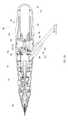
- FIG. 1Ais a perspective view of a self-contained subdermal cryogenic remodeling probe and system, according to an embodiment of the invention.
- FIG. 1Bis a partially transparent perspective view of the self-contained probe of FIG. 1A , showing internal components of the cryogenic remodeling system and schematically illustrating replacement treatment needles for use with the disposable probe.
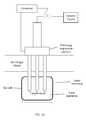
- FIG. 2Aschematically illustrates components that may be included in the treatment system.
- FIG. 2Bis a cross-sectional view of the system of FIG. 1A , according to an embodiment of the invention.
- FIGS. 2C and 2Dare cross-sectional views showing operational modes of the system of FIG. 2B .
- FIGS. 3A-3Billustrate an exemplary embodiment of a clad needle probe, according to an embodiment of the invention.
- FIG. 4is a flow chart illustrating an exemplary algorithm for heating the needle probe of FIG. 3A , according to an embodiment of the invention.
- FIG. 5is a flow chart schematically illustrating a method for treatment using the disposable cryogenic probe and system of FIGS. 1A and 1B , according to an embodiment of the invention.
- FIG. 6Ais a flow chart schematically illustrating a method for treatment using the disposable cryogenic probe and system of FIGS. 1A and 1B , according to an embodiment of the invention.
- FIG. 6Bis a flow chart schematically illustrating a method for treatment using the disposable cryogenic probe and system of FIGS. 1A and 1B , according to an embodiment of the invention.
- FIG. 6Cis a simplified depiction of the method of treatment of FIG. 6B .
- Embodiments of the inventionwill facilitate remodeling of target tissues disposed at and below the skin, optionally to treat a cosmetic defect, a lesion, a disease state, and/or so as to alter a shape of the overlying skin surface, while providing protection to portions of non-target tissues, including the skin, which are directly above the target tissues.
- At least some embodiments of the present inventionmay improve upon at least some aspects of previous systems. At least some previous systems relied upon the user to mechanically open and close a valve. Some of the present embodiments may improve upon these previous systems by performing this function via electronic control of an electromechanical valve. The improvement enables the system to perform repeatable, automated refrigeration cycles. It also enables monitoring and control for safe, reliable performance.
- At least some embodimentsenable what previously required separate mechanical and electrical connection of the probe to be performed with one assembly step and may be safer to use during installation and removal. Some embodiments also or alternatively enable power and control through a mains operated, external control unit; or fully integrating control and power through component selection in particular the electro-mechanical valve. Some embodiments also or alternatively enable the full integration of the refrigerant into the handpiece by adapting refrigerant cartridges to provide cryogen fluid to an attached needle probe.
- Embodiments of the disclosed systemmay be hand held providing ease of use.
- the systemmay also enable untethered or disassembled configurations that allow the system to be easily transportable.
- the systemmay include sensors and automation for added safety and reliability.
- the probe and cartridgeare designed for safe and reliable use even in instances where they are not handled following normal operating instructions.
- a user interfacemay provide key information to the user regarding the system status.
- the present inventionmay be the amelioration of lines and wrinkles, particularly by inhibiting muscular contractions which are associated with these cosmetic defects so as so improve an appearance of the patient.
- many embodiments of the inventionwill at least in part employ cold to immobilize muscles.
- nerves, muscles, and associated tissuesmay be temporarily immobilized using moderately cold temperatures of 10° C. to ⁇ 5° C. without permanently disabling the tissue structures.
- a needle probe or other treatment devicecan be used to identify a target tissue structure in a diagnostic mode with these moderate temperatures, and the same probe (or a different probe) can also be used to provide a longer term or permanent treatment, optionally by ablating the target tissue zone and/or inducing apoptosis at temperatures from about ⁇ 5° C. to about ⁇ 50° C.
- apoptosismay be induced using treatment temperatures from about ⁇ 1° C. to about ⁇ 15° C., or from about ⁇ 1° C.
- cryogenic coolingfor treatment of cosmetic and other defects may be found in commonly assigned U.S. Pat. No.
- embodiments of the inventionmay also find applications for treatments of subdermal adipose tissues, benign, pre-malignant lesions, malignant lesions, acne and a wide range of other dermatological conditions (including dermatological conditions for which cryogenic treatments have been proposed and additional dermatological conditions), and the like.
- Embodiments of the inventionmay also find applications for alleviation of pain, including those associated with muscle spasms as disclosed in commonly assigned U.S. Pub. No. 2009/0248001 entitled “Pain Management Using Cryogenic Remodeling” the full disclosure of which is incorporated herein by reference.
- a system for cryogenic remodelingincludes a self-contained probe handpiece generally having a proximal end 12 and a distal end 14 .
- a handpiece body or housing 16has a size and ergonomic shape suitable for being grasped and supported in a surgeon's hand or other system operator.
- a cryogenic cooling fluid supply 18also referred to as cryogen cartridge
- a supply valve 32and an optional electrical power source 20 are found within housing 16 , along with a circuit 22 S having a processor for controlling cooling applied by self-contained system 10 in response to actuation of an input 24 .
- electrical powercan be applied through a cord from a remote power source.
- electrical power source 20can be an emergency back-up power source in the advent of a power delivery failure from the remote power source.
- Power source 20also supplies power to heater element 44 in order to heat the proximal region of probe 26 thereby helping to prevent unwanted skin damage, and a temperature sensor 48 adjacent the proximal region of probe 26 helps monitor probe temperature. Additional details on the heater 44 and temperature sensor 48 are described in greater detail below.
- supply valve 32controls the flow of cryogenic cooling fluid from fluid supply 18 .
- Some embodimentsmay, at least in part, be manually activated, such as through the use of a manual supply valve and/or the like, so that processors, electrical power supplies, and the like may not be required.
- Probe 26Extending distally from distal end 14 of housing 16 is a tissue-penetrating cryogenic cooling probe 26 .
- Probe 26is thermally coupled to a cooling fluid path extending from cooling fluid source 18 , with the exemplary probe comprising a tubular body receiving at least a portion of the cooling fluid from the cooling fluid source therein.
- the exemplary probe 26comprises a 27 g needle having a sharpened distal end that is axially sealed.
- Probe 26may have an axial length between distal end 14 of housing 16 and the distal end of the needle of between about 0.5 mm and 5 cm, preferably having a length from about 3 mm to about 10 mm.
- needlesmay comprise a stainless steel tube with an inner diameter of about 0.006 inches and an outer diameter of about 0.012 inches, while alternative probes may comprise structures having outer diameters (or other lateral cross-sectional dimensions) from about 0.006 inches to about 0.100 inches.
- needle probe 26will comprise a 16 g or smaller size needle, often comprising a 20 g needle or smaller, typically comprising a 25, 26, 27, 28, 29, or 30 g or smaller needle.
- probe 26may comprise two or more needles arranged in a linear array, such as those disclosed in previously incorporated U.S. Pat. No. 7,850,683.
- Another exemplary embodiment of a probe having multiple needle probe configurationsallow the cryogenic treatment to be applied to a larger or more specific treatment area.
- Other needle configurations that facilitate controlling the depth of needle penetration and insulated needle embodimentsare disclosed in commonly assigned U.S. Patent Publication No. 2008/0200910 entitled “Replaceable and/or Easily Removable Needle Systems for Dermal and Transdermal Cryogenic Remodeling,” the entire content of which is incorporated herein by reference.
- Multiple needle arraysmay also be arrayed in alternative configurations such as a triangular or square array.
- Arraysmay be designed to treat a particular region of tissue, or to provide a uniform treatment within a particular region, or both.
- needle 26is releasably coupled with body 16 so that it may be replaced after use with a sharper needle (as indicated by the dotted line) or with a needle having a different configuration.
- the needlemay be threaded into the body, it may be press fit into an aperture in the body or it may have a quick disconnect such as a detent mechanism for engaging the needle with the body.
- a quick disconnect with a check valveis advantageous since it permits decoupling of the needle from the body at any time without excessive coolant discharge. This can be a useful safety feature in the event that the device fails in operation (e.g.
- valve failureallowing an operator to disengage the needle and device from a patient's tissue without exposing the patient to coolant as the system depressurizes. This feature is also advantageous because it allows an operator to easily exchange a dull needle with a sharp needle in the middle of a treatment.
- coupling mechanismsmay be used.
- the exemplary cooling fluid supply 18comprises a canister, sometimes referred to herein as a cartridge, containing a liquid under pressure, with the liquid preferably having a boiling temperature of less than 37° C.
- a canistersometimes referred to herein as a cartridge
- the liquidpreferably having a boiling temperature of less than 37° C.
- a supply valve 32may be disposed along the cooling fluid flow path between canister 18 and probe 26 , or along the cooling fluid path after the probe so as to limit coolant flow thereby regulating the temperature, treatment time, rate of temperature change, or other cooling characteristics.
- the valvewill often be powered electrically, per the direction of processor 22 S, but may at least in part be manually powered.
- the exemplary power source 20comprises a rechargeable or single-use battery. Additional details about valve 32 are disclosed below and further disclosure on the power source 20 may be found in commonly assigned Int'l Pub. No. WO 2010/075438 entitled “Integrated Cryosurgical Probe Package with Fluid Reservoir and Limited Electrical Power Source,” the entire contents of which is incorporated herein by reference.
- the exemplary cooling fluid supply 18comprises a single-use canister.
- the canister and cooling fluid thereinmay be stored and/or used at (or even above) room temperature.
- the canistermay have a frangible seal or may be refillable, with the exemplary canister containing liquid nitrous oxide, N 2 O.
- a variety of alternative cooling fluidsmight also be used, with exemplary cooling fluids including fluorocarbon refrigerants and/or carbon dioxide.
- the quantity of cooling fluid contained by canister 18will typically be sufficient to treat at least a significant region of a patient, but will often be less than sufficient to treat two or more patients.
- An exemplary liquid N 2 O canistermight contain, for example, a quantity in a range from about 1 gram to about 40 grams of liquid, more preferably from about 1 gram to about 35 grams of liquid, and even more preferably from about 7 grams to about 30 grams of liquid.
- Processor 22will typically comprise a programmable electronic microprocessor embodying machine readable computer code or programming instructions for implementing one or more of the treatment methods described herein.
- the microprocessorwill typically include or be coupled to a memory (such as a non-volatile memory, a flash memory, a read-only memory (“ROM”), a random access memory (“RAM”), or the like) storing the computer code and data to be used thereby, and/or a recording media (including a magnetic recording media such as a hard disk, a floppy disk, or the like; or an optical recording media such as a CD or DVD) may be provided.
- a memorysuch as a non-volatile memory, a flash memory, a read-only memory (“ROM”), a random access memory (“RAM”), or the like
- a recording mediaincluding a magnetic recording media such as a hard disk, a floppy disk, or the like; or an optical recording media such as a CD or DVD
- Suitable interface devicessuch as digital-to-analog or analog-to-digital converters, or the like
- input/output devicessuch as USB or serial I/O ports, wireless communication cards, graphical display cards, and the like
- processor 22may be integrated on a single processor board and may run a single program or may make use of a plurality of boards running a number of different program modules in a wide variety of alternative distributed data processing or code architectures.
- Supply valve 32may comprise an electrically actuated solenoid valve, a motor actuated valve or the like operating in response to control signals from controller 22 , and/or may comprise a manual valve.
- Exemplary supply valvesmay comprise structures suitable for on/off valve operation, and may provide venting of the fluid source and/or the cooling fluid path downstream of the valve when cooling flow is halted so as to limit residual cryogenic fluid vaporization and cooling.
- valvemay be actuated by the controller in order to modulate coolant flow to provide high rates of cooling in some instances where it is desirable to promote necrosis of tissue such as in malignant lesions and the like or slow cooling which promotes ice formation between cells rather than within cells when necrosis is not desired.
- More complex flow modulating valve structuresmight also be used in other embodiments.
- other applicable valve embodimentsare disclosed in previously incorporated U.S. Pub. No. 2008/0200910.
- an optional heatermay be used to heat cooling fluid supply 18 so that heated cooling fluid flows through valve 32 and through a lumen 34 of a cooling fluid supply tube 36 .
- Supply tube 36is, at least in part, disposed within a lumen 38 of needle 26 , with the supply tube extending distally from a proximal end 40 of the needle toward a distal end 42 .
- the exemplary supply tube 36comprises a fused silica tubular structure (not illustrated) having a polymer coating and extending in cantilever into the needle lumen 38 .
- Supply tube 36may have an inner lumen with an effective inner diameter of less than about 200 ⁇ m, the inner diameter often being less than about 100 ⁇ m, and typically being less than about 40 ⁇ m. Exemplary embodiments of supply tube 36 have inner lumens of between about 15 and 50 ⁇ m, such as about 30 ⁇ m. An outer diameter or size of supply tube 36 will typically be less than about 1000 ⁇ m, often being less than about 800 ⁇ m, with exemplary embodiments being between about 60 and 150 ⁇ m, such as about 90 ⁇ m or 105 ⁇ m.
- the tolerance of the inner lumen diameter of supply tubing 36will preferably be relatively tight, typically being about +/ ⁇ 10 ⁇ m or tighter, often being +/ ⁇ 5 ⁇ m or tighter, and ideally being +/ ⁇ 3 ⁇ m or tighter, as the small diameter supply tube may provide the majority of (or even substantially all of) the metering of the cooling fluid flow into needle 26 .
- Previously incorporated U.S. Patent Publication No. 2008/0200910discloses additional details on the needle 26 along with various alternative embodiments and principles of operation.
- the cooling fluid injected into lumen 38 of needle 26will typically comprise liquid, though some gas may also be injected. At least some of the liquid vaporizes within needle 26 , and the enthalpy of vaporization cools the needle and also the surrounding tissue engaged by the needle.
- An optional heater 44(illustrated in FIG. 1B ) may be used to heat the proximal region of the needle 26 in order to prevent unwanted skin damage in this area, as discussed in greater detail below. Controlling a pressure of the gas/liquid mixture within needle 26 substantially controls the temperature within lumen 38 , and hence the treatment temperature range of the tissue.
- a relatively simple mechanical pressure relief valve 46may be used to control the pressure within the lumen of the needle, with the exemplary valve comprising a valve body such as a ball bearing, urged against a valve seat by a biasing spring.
- An exemplary relief valveis disclosed in U.S. Provisional Patent Application No. 61/116,050 previously incorporated herein by reference.
- the relief valveallows better temperature control in the needle, minimizing transient temperatures. Further details on exhaust volume are disclosed in previously incorporated U.S. Pat. Pub. No. 2008/0200910.
- the heater 44may be thermally coupled to a thermally responsive element 50 , which is supplied with power by the controller 22 and thermally coupled to a proximal portion of the needle 26 .
- the thermally responsive element 50can be a block constructed from a material of high thermal conductivity and low heat capacity, such as aluminum.
- a temperature sensor 52e.g., thermistor, thermocouple
- the controller 22can be configured to receive temperature information of the thermally responsive element 50 via the temperature sensor 52 in order to provide the heater 44 with enough power to maintain the thermally responsive element 50 at a particular temperature.
- the controller 22can be further configured to monitor power draw from the heater 44 in order to characterize tissue type, perform device diagnostics, and/or provide feedback for a tissue treatment algorithm. This can be advantageous over monitoring temperature alone, since power draw from the heater 44 can vary greatly while temperature of the thermally responsive element 50 remains relatively stable. For example, during treatment of target tissue, maintaining the thermally responsive element 50 at 40° C. during a cooling cycle may take 1.0 W initially and is normally expected to climb to 1.5 W after 20 seconds, due to the needle 26 drawing in surrounding heat. An indication that the heater is drawing 2.0 W after 20 seconds to maintain 40° C. can indicate that an aspect of the system 10 is malfunctioning and/or that the needle 26 is incorrectly positioned. Correlations with power draw and correlated device and/or tissue conditions can be determined experimentally to determine acceptable treatment power ranges.
- metering coolant flowcould maintain a large thermal gradient at its outside edges. This may be particularly advantageous in applications for creating an array of connected cooling zones (i.e, fence) in a treatment zone, as time would be provided for the treatment zone to fully develop within the fenced in portion of the tissue, while the outer boundaries maintained a relatively large thermal gradient due to the repeated application and removal of refrigeration power.
- Thiscould provide a mechanism within the body of tissue to thermally regulate the treatment zone and could provide increased ability to modulate the treatment zone at a prescribed distance from the surface of the skin.
- a related treatment algorithmcould be predefined, or it could be in response to feedback from the tissue.
- Such feedbackcould be temperature measurements from the needle 26 , or the temperature of the surface of the skin could be measured.
- monitoring temperature at the needle 26is impractical due to size constraints.
- operating performance of the sensorless needle 26can be interpolated by measuring characteristics of thermally coupled elements, such as the thermally responsive element 50 .
- One such measured characteristiccould be the power required to heat the thermally responsive element 50 , therefore the medium which the thermally responsive element 50 , or the thermally coupled needle 26 , is coupled to. For example, very little power would be required to warm and maintain the temperature of the thermally conductive block in air.
- the thermally responsive element 50could be used to determine whether the thermally responsive element 50 , or the thermally coupled needle 26 , has sufficient contact with skin due to the thermal load of the skin. This would be useful for ensuring that the needle 26 was correctly placed prior to treatment. This could be done without flowing coolant to the needle 26 , or alternatively, by metering very little coolant to the needle 26 , i.e., less than what is required to treat tissue.
- thermally conductive element 50there may be more or less residual refrigerant that affected the thermally conductive element 50 depending upon how much thermal load was applied to the needle 26 . This could be used to characterize the tissue(s) the probes was placed into. For example, there would be relatively more heat drawn from the thermally conductive element 50 in insulative tissue such as adipose tissue. Since thermal load on the distal end of the needle 26 would be affected by the development of an cooling zone around the needle 26 , the thermally conductive element 50 could be used to determine the state of the needle 26 as ice forms.
- Power feedbackcould provide feedback to regulate the delivery of refrigerant based upon the tissue, formation of ice, contact with the skin, or other useful information.
- the feedbackcould be used to control the treatment zone to the desired configuration.
- the feedbackcould be used to diagnose a treatment failure. For instance if the probe had three needles delivering refrigerant, but only two were working, the thermally conductive element could detect the failure and inform the user.
- Temperature feedbackcould also used in conjunction with power feedback. Temperature sensing could occur on the needle 26 if possible, on the thermally conductive element 50 , and/or remote to the thermally conductive element.
- the thermally conductive element 50could reside on a detachable cooling probe and be thermally coupled to a handpiece, with feedback and control circuits located within the handpiece (e.g., housing 16 ). This could be advantageous to provide a low cost detachable cooling probe and for system reliability, since the probe could be coupled to a controller in the reusable handpiece. Thus, practically offering higher capability due to the ability to afford more precise controls.
- the thermally conductive element 50could be thermally coupled to the needle 26 at a proximal tissue interface.
- excess refrigerantwould return through the needle.
- the excess refrigerantcould be in the form of cool gas or liquid that had not yet converted to gas through the latent heat of vaporization.
- the excess refrigerantcould change dependent upon the tissue(s) the probe was in, variations in tissue temperature, presence of local heat sources (arteries and veins), and metabolic effects.
- the excess refrigerantcould also be affected by the effect of the treatment over time. In particular, changes in thermal loading as a function of the cooling of adjacent tissue and the formation of ice.
- the thermally conductive elementcould be tailored to deliver comparable, or more heat than the available refrigeration power.
- the transfer of heat into the tissuewould be constrained by the material and dimensions of the needle.
- a relatively long needlemight receive enough heat from the adjacent tissue along its length to prevent the freeze zone from extending more proximally than desired.
- the ability to transfer more heat into the tissuecould be achieved by providing improved thermal coupling from the thermally conductive block into the tissue. This could be achieved by increasing the diameter and or wall thickness of the needle, or through the addition of thermally conductive cladding to the proximal portion of the needle.
- This couplingcould also be optimized to extend the length of the protection desired. For instance, the cladding or portion of increased wall thickness and diameter could extend through the dermis and subdermal fat layer, then end.
- the cooling of the tip and the heating of more proximal tissuecould be uncoupled. This could be achieved by applying an insulative material between the cladding and the underlying needle. Therefore, the heat through the protected portion of tissue could be controlled independent of the refrigeration of the tip. This would be advantageous in that the heat added would not compromise the refrigerant delivered to the tip and the refrigerant would not comprise the heat added to the tissue.
- Additional methods of monitoring cooling and maintaining an unfrozen portion of the needleinclude the addition of a heating element and/or monitoring element into the needle itself. This could consist of a small thermistor or thermocouple, and a wire that could provide resistive heat. Other power sources could also be applied such as infrared light, radiofrequency heat, and ultrasound. These systems could also be applied together dependent upon the control of the treatment zone desired.
- Supply valve 32may comprise an electrically actuated solenoid valve, a motor actuated valve or the like operating in response to control signals from controller 22 , and/or may comprise a manual valve.
- Exemplary supply valvesmay comprise structures suitable for on/off valve operation, and may provide venting of the fluid source and/or the cooling fluid path downstream of the valve when cooling flow is halted so as to limit residual cryogenic fluid vaporization and cooling.
- valvemay be actuated by the controller in order to modulate coolant flow to provide high rates of cooling in some instances where it is desirable to promote necrosis of tissue such as in malignant lesions and the like or slow cooling which promotes ice formation between cells rather than within cells when necrosis is not desired.
- More complex flow modulating valve structuresmight also be used in other embodiments.
- other applicable valve embodimentsare disclosed in previously incorporated U.S. Pub. No. 2008/0200910.
- an optional cooling supply heatermay be used to heat cooling fluid supply 18 so that heated cooling fluid flows through valve 32 and through a lumen 34 of a cooling fluid supply tube 36 .
- safety mechanismcan be included so that the cooling supply is not overheated. Examples of such embodiments are disclosed in commonly assigned Int'l. Pub. No. WO 2010075438, the entirety of which is incorporated by reference herein.
- Supply tube 36is, at least in part, disposed within a lumen 38 of needle 26 , with the supply tube extending distally from a proximal end 40 of the needle toward a distal end 42 .
- the exemplary supply tube 36comprises a fused silica tubular structure (not illustrated) having a polymer coating and extending in cantilever into the needle lumen 38 .
- Supply tube 36may have an inner lumen with an effective inner diameter of less than about 200 ⁇ m, the inner diameter often being less than about 100 ⁇ m, and typically being less than about 40 ⁇ m.
- Exemplary embodiments of supply tube 36have inner lumens of between about 15 and 50 ⁇ m, such as about 30 ⁇ m.
- An outer diameter or size of supply tube 36will typically be less than about 1000 ⁇ m, often being less than about 800 ⁇ m, with exemplary embodiments being between about 60 and 150 ⁇ m, such as about 90 ⁇ m or 105 ⁇ m.
- the tolerance of the inner lumen diameter of supply tubing 36will preferably be relatively tight, typically being about +/ ⁇ 10 ⁇ m or tighter, often being +/ ⁇ 5 ⁇ m or tighter, and ideally being +/ ⁇ 3 ⁇ m or tighter, as the small diameter supply tube may provide the majority of (or even substantially all of) the metering of the cooling fluid flow into needle 26 . Additional details on various aspects of needle 26 along with alternative embodiments and principles of operation are disclosed in greater detail in U.S. Patent Publication No.
- the cooling fluid injected into lumen 38 of needle 26will typically comprise liquid, though some gas may also be injected. At least some of the liquid vaporizes within needle 26 , and the enthalpy of vaporization cools the needle and also the surrounding tissue engaged by the needle.
- An optional heater 44(illustrated in FIG. 1B ) may be used to heat the proximal region of the needle in order to prevent unwanted skin damage in this area, as discussed in greater detail below. Controlling a pressure of the gas/liquid mixture within needle 26 substantially controls the temperature within lumen 38 , and hence the treatment temperature range of the tissue.
- a relatively simple mechanical pressure relief valve 46may be used to control the pressure within the lumen of the needle, with the exemplary valve comprising a valve body such as a ball bearing, urged against a valve seat by a biasing spring.
- the relief valveallows better temperature control in the needle, minimizing transient temperatures. Further details on exhaust volume are disclosed in U.S. Patent Publication No. 2008/0200910, previously incorporated herein by reference.
- FIG. 2Bshows a cross-section of the housing 16 .
- This embodiment of the housing 16is powered by an external source, hence the attached cable, but could alternatively include a portable power source.
- the housingincludes a cartridge assembly 50 .
- the cartridge assembly 50is connectable with a cartridge receiver 52 of the handpiece 16 , which is configured to hold a pressured refrigerant cartridge.
- the cartridge receiver 52includes an elongated cylindrical passage 54 , which is dimensioned to hold a commercially available cooling fluid cartridge.
- a distal portion of the cartridge receiver 52includes a filter device 56 , which has an elongated conical shape.
- the cartridge assembly 50is largely integrated into the housing 10 , however, in alternative embodiments, the cartridge assembly 50 is a wholly separate assembly, which may be pre-provided with a coolant fluid source 18 .
- the filter device 56fluidly couples the coolant fluid source (cartridge) 18 at a proximal end to the valve 32 at a distal end.
- the filter device 56includes at least one particulate filter 58 .
- a particulate filter 58 at each proximal and distal end of the filter device 56is included.
- the particulate filter 58can be configured to prevent particles of a certain size from passing through.
- the particulate filter 58can be constructed as a microscreen having a plurality of passages less than 2 microns in width, and thus particles greater than 2 microns would not be able to pass.
- the filter device 56also includes a molecular filter 60 that is configured to capture fluid impurities.
- the molecular filter 60is a plurality of filter media (e.g., pellets, powder, particles) configured to trap molecules of a certain size.
- the filter mediacan comprise molecular sieves having pores ranging from 1-20 ⁇ . In another example, the pores have an average size of 5 ⁇ .
- the molecular filter 60can have two modalities. In a first mode, the molecular filter 60 will filter fluid impurities received from the cartridge 18 . However, in another mode, the molecular filter 60 can capture impurities within the valve 32 and fluid supply tube 36 when the system 10 is not in use, i.e., when the cartridge 18 is not fluidly connected to the valve 32 .
- fluid impuritiesmay leach out from various aspects of the system 10 .
- These impuritiescan include trapped moisture in the form of water molecules and chemical gasses. The presence of these impurities is believed to hamper cooling performance of the system 10 .
- the filter device 56can act as a desiccant that attracts and traps moisture within the system 10 , as well as chemicals out gassed from various aspects of the system 10 .
- the cartridge 18can be held by the cartridge receiver 52 such that the cartridge 18 remains intact and unpunctured. In this inactive mode, the cartridge is not fluidly connected to the valve 32 .
- a removable cartridge cover 62can be attached to the cartridge receiver 52 such that the inactive mode is maintained while the cartridge is held by the system 10 .
- the cartridge cover 62can be removed and supplied with a new cartridge 18 containing a cooling fluid, or an entire new cartridge assembly 50 . In some cases, a procedure may require a plurality of cartridge assemblies 50 .
- the cartridge cover 62can then be reattached to the cartridge receiver 52 by turning the cartridge cover 62 until female threads 64 of the cartridge cover 62 engage with male threads of the cartridge receiver 52 .
- the cartridge cover 62can be turned until resilient force is felt from an elastic seal 66 , as shown in FIG. 2C .
- the cartridge cover 62can be further turned until the distal tip of the cartridge 18 is punctured by a puncture pin 68 , as shown in FIG. 2D .
- cooling fluidescapes the cartridge by flowing through the filter device 56 , where the impurities within the cooling fluid are captured.
- the purified cooling fluidthen passes to the valve 32 , and onto the coolant supply tube 36 to cool the probe 26 .
- the filter device, or portions thereof,is replaceable.
- the entire handpiecemay be single use and/or disposable.
- the cryogen cartridge 18is removeably connected at its proximal end to a cartridge cover 62 by a spring device 70 .
- the cryogen cartridge 18is removeably connected at its distal end to the filter assembly 66 via an interference fit with the elastic seal 66 .
- the body of the filter assembly 56is a nose cone 72 that contains the molecular filter 60 , particulate filters 58 , and the puncture pin 68 .
- a proximal portion of the nose cone 72has an internal diameter that engages with the elastic seal 66 via spring device 74 .
- the nose cone 72is installed on the tip of the cryogen cartridge 18 .
- the handpiece 16has a mating element that the nose cone 72 engages with.
- a distal portion of the nose cone 72has a flanged or stepped portion 76 .
- a switch 78 of the handpiece 16engages with the stepped portion 76 to provide an indication of positive engagement.
- the cartridge assembly 50is attachable to into the handpiece 16 .
- the threaded capis then rotated within the mating threads of the handpiece 16 .
- the rotation of the cartridge cover 62advances the cryogen cartridge 18 within the handpiece 16 .
- the nose cone 72extending from the end of the cartridge 18 engages a port 80 within the handpiece 16 and advances until an o-ring seal on the nose cone 72 is fully seated within the bore of the handpiece 16 mating port.
- the seated distanceis controlled by a separate step on the cartridge nose cone 72 engaging the cartridge housing of the handpiece 16 . Therefore once the o-ring is seated within the handpiece port 80 , no additional loading is placed on the mated port 80 .
- the cartridge receiver 52 of the handpiece 16can be constructed as one rigid element, preferably from hard anodized aluminum for its rigidity, heat transfer and electrical isolation characteristics.
- the cryogen cartridge 18advances into the now seated nose cone 72 . Further advancement engages a frangible seal at the end of the cryogen cartridge 18 with the puncture pin 68 seated in the nose cone. Puncturing the seal releases cryogen through the bore of the puncture pin 68 . To prevent leakage, the frangible seal on the cryogen cylinder secures to the puncture pin 68 . In addition a secondary elastomeric seal seals against the distal end of the cryogen cartridge 18 . One or both of these may be used to prevent cryogen leakage.
- the cryogenflows through a 2 micron mesh screen, followed by the molecular filter 60 , and by the particulate filter 58 .
- the mesh screens 58serve to remove particulate from the refrigerant stream.
- the molecular sieves columnserves to remove moisture, oils and other contaminants from the refrigerant.
- the refrigerantexits the cryogen cartridge 18 in a pure form that enables reliable refrigeration performance.
- the nose coneengages the switch 78 during installation enabling the handpiece to recognize the presence of the cartridge.
- the cryogen pressureis regulated by heating the cryogen cylinder using a temperature regulated kapton heater 82 that engages the cryogen cartridge 18 along its length and around its diameter.
- the cartridge assembly 50is removed by unthreading the cartridge cover 62 and removing the cartridge.
- the engagement mechanism of the cartridge cover 62 to the cryogen cartridge 18ensures a pressurized cartridge 18 cannot be fluidly connected with the handpiece 16 without the cartridge cover 62 securing it in place.
- the nose cone 72is removed with the cartridge by having secure attachment to the elastic seal 66 at the end of the refrigerant cartridge. Secure attachment can be in the form of an interference fit between the parts or physical latching of the parts together.
- the probe 26has sealed tip, 20 g or smaller needles.
- the needleshave sharpened tips for percutaneous insertion.
- the needlesare fully sealed.
- Cryogen fluidis delivered into the needles through an internal tube.
- the cryogenexpands and evaporates within the tips of the needles cooling the surrounding tissue.
- the cryogen exhaustpasses up the needle and exhausts the system outside of the patient and into the treatment room.
- the probe 26threads into a mating manifold in the handpiece 16 .
- the probehas a sealing o-ring that mates with the handpiece and isolates the refrigerant entering the probe from the cryogen exhaust.
- the probe 26has a circuit board with pads that engage pogo pin electrical connectors on the handpiece. As the probe 26 is threaded into the handpiece 16 , the threads first ensure secure mechanical engagement. Further threading passes the inlet o-ring seal past the exhaust port on the handpiece 16 . Then electrical engagement occurs enabling the system to recognize the probe presence and enabling system functionality. Finally, there is an index mark and a feature that provides an audible and tactile click at the rotation stop indicating full probe engagement. Similarly, removal of the probe first results in electrical disengagement.
- the internal fluid pathpasses first through a 2 micron particle filter, then enters a tube within the probe.
- the fluid paththen separates into multiple smaller tubes for each needle that extend into the needle tips.
- the exhausted gaspasses through the annular space between the delivery tube and internal bore of the needles, then exits through the handpiece.
- a second o-ringisolates the exhausting refrigerant. This forces the exhaust to pass a sensor in the handpiece.
- the sensorcould be a temperature sensor used to detect proper performance of the system by measuring the temperature of the exhaust stream.
- the needles on the probe 26are attached with thermally-conductive epoxy to a temperature-regulated, hard-anodized aluminum block.
- the attachmentprovides thermal coupling and electrical isolation.
- the aluminum block temperatureis regulated with a temperature sensor and resistive heating element.
- the electrical elementsare attached to the block using thermal epoxy that provides thermal coupling and electrical isolation. Power is supplied to the electrical elements to regulate the temperature.
- the heating element and sensorare electrically coupled to the circuit board that mates with the handpiece pogo pins. Therefore, engagement of the probe 26 enables the system to provide temperature regulation of the block and therefore the needles.
- the electrical circuitcould contain an element such as a fuse that can be disabled once the probe has been used preventing reuse of the probe.
- the probe 26could have an identifier such as a resistor or other identification chip that could identify and even provide instructions to the handpiece on the proper functional use of the system.
- an identifiercan include information about the gage of needles of the probe 26 , the length of needles of the probe 26 , and/or the type of needle of the probe 26 .
- a particular treatment algorithmcould be enabled.
- the handpiece 16mates with the probe 26 and cryogen cartridge 18 , and also with the control unit.
- the handpieceis plumbed from the cartridge to the probe.
- An electromechanical valveis present that isolates refrigerant from the probe.
- a second manual mechanical valveis present in the event the electromechanical valve errors and does not stop flow. Engagement of the mechanical valve vents the downstream refrigerant, preventing further flow of refrigerant to the electromechanical valve and probe.
- the electromechanical valveis a stepper motor with a plunger that compresses an elastomeric ring. Actuation of the valve opens or closes the fluid path through the elastomeric ring. The selection of a stepper motor enables the use of the system with mains power or self-contained battery power.
- Treatment operationincluding opening and closing the valve is programmed into the system and controlled through the control unit. The treatment cycle is initiated through pressing an electromechanical switch on the handpiece 16 . The treatment can be stopped by pressing the same switch.
- the fluid pathis constructed to have a minimal amount of volume enabling the system to be responsive and enabling the use of small refrigerant cartridges that keep the system small, light and easy to handle.
- the fluid pathis constructed primarily from thermally insulative components. This enables the refrigeration power to be available for cooling the probe needles rather than cooling elements of the system. In addition this makes the system robust to environmental conditions that could heat or cool the refrigerant therefore preventing inconsistent refrigeration cycle performance.
- Sensorsare present in the handpiece to determine the state of the system. Selection of sensors that require low power, such as thermistors, enables the system to be mains powered or alternatively battery powered and ensure the system remains small and light for ease of handling. Sensors are used to ensure proper function such as: opening and closing of the valve during treatment, ensuring proper performance of the probe, and maintaining cartridge pressure. Sensors also detect the state of the system ensuring safe and reliable performance of the system including: monitoring the system for leaks, ensuring the probe and cartridge are engaged and ready for use prior to enabling initiating the treatment cycle, and ensuring the heaters on the probe and cartridge assembly 50 are performing normally.
- a microcontroller 22 S on the handpieceacts as a slave to a microcontroller in the control unit 22 .
- the handpiece 16 microcontroller 22 Sreads sensors on the handpiece and issues commands based upon the control unit commands. Communication between the handpiece and control unit and power supply to the handpiece are provide through a tether between the handpiece and control unit.
- the control unit 22contains a microcontroller that commands the handpiece 16 to perform functions. Feedback is provided to the control unit from the microcontroller 22 S on the handpiece. The control unit 22 provides feedback to the user audibly and visually as to the system state. The control unit is mains powered and has backup power provided from a super cap. The backup power enables the system to notify the user and safely shut the system down in the event of power disruption.
- resistive heater element 314is disposed near the needle hub 318 and near a proximal region of needle shaft 302 .
- the resistance of the heater elementis preferably 1 ⁇ to 1K ⁇ , and more preferably from 5 ⁇ to 50 ⁇ .
- a temperature sensor 312such as a thermistor or thermocouple is also disposed in the same vicinity.
- the heater 314may be turned on in order to heat the hub 318 and proximal region of needle shaft 302 , thereby preventing this portion of the device from cooling down as much as the remainder of the needle shaft 302 .
- the temperature sensor 312may provide feedback to controller 22 and a feedback loop can be used to control the heater 314 .
- the cooling power of the nitrous oxidewill eventually overcome the effects of the heater, therefore the microprocessor may also be programmed with a warning light and/or an automatic shutoff time to stop the cooling treatment before skin damage occurs.
- An added benefit of using such a heater elementis the fact that the heat helps to moderate the flow of cooling fluid into the needle shaft 302 helping to provide more uniform coolant mass flow to the needles shaft 302 with more uniform cooling resulting.
- FIG. 3Aillustrates a heater fixed to the probe hub.
- the heatermay float, thereby ensuring proper skin contact and proper heat transfer to the skin. Examples of floating heaters are disclosed in commonly assigned Int'l Pub. No. WO 2010/075448 entitled “Skin Protection for Subdermal Cyrogenic Remodelling for Cosmetic and Other Treatments”, the entirety of which is incorporated by reference herein.
- three needlesare illustrated.
- a single needlemay be used, as well as two, four, five, six, or more needles may be used.
- a plurality of needlesmay be arranged in any number of patterns.
- a single linear arraymay be used, or a two dimensional or three dimensional array may be used.
- two dimensional arraysinclude any number of rows and columns of needles (e.g. a rectangular array, a square array, elliptical, circular, triangular, etc.), and examples of three dimensional arrays include those where the needle tips are at different distances from the probe hub, such as in an inverted pyramid shape.
- FIG. 3Billustrates a cross-section of the needle shaft 302 of needle probe 300 .
- the needle shaftcan be conductively coupled (e.g., welded, conductively bonded, press fit) to a conductive heater 314 to enable heat transfer therebetween.
- the needle shaft 302is generally a small (e.g., 20-30 gauge) closed tip hollow needle, which can be between about 0.2 mm and 5 cm, preferably having a length from about 0.3 cm to about 0.6 cm.
- the conductive heater element 314can be housed within a conductive block 315 of high thermally conductive material, such as aluminum and include an electrically insulated coating, such as Type III anodized coating to electrically insulate it without diminishing its heat transfer properties.
- the conductive block 315can be heated by a resister or other heating element (e.g. cartridge heater, nichrome wire, etc.) bonded thereto with a heat conductive adhesive, such as epoxy.
- a thermistorcan be coupled to the conductive block 315 with heat conductive epoxy allows temperature monitoring.
- Other temperature sensorsmay also be used, such as a thermocouple.
- a cladding 320 of conductive materialis directly conductively coupled to the proximal portion of the shaft of needle shaft 302 , which can be stainless steel.
- the cladding 320is a layer of gold, or alloys thereof, coated on the exterior of the proximal portion of the needle shaft 302 .
- the exposed length of cladding 320 on the proximal portion of the needleis 2 mm.
- the cladding 320be of a thickness such that the clad portion has a diameter ranging from 0.017-0.020 in., and in some embodiments 0.0182 in. Accordingly, the cladding 320 can be conductively coupled to the material of the needle 302 , which can be less conductive, than the cladding 320 .
- the cladding 320can include sub-coatings (e.g., nickel) that promote adhesion of an outer coating that would otherwise not bond well to the needle shaft 302 .
- sub-coatingse.g., nickel
- Other highly conductive materialscan be used as well, such as copper, silver, aluminum, and alloys thereof.
- a protective polymer or metal coatingcan cover the cladding to promote biocompatibility of an otherwise non-biocompatible but highly conductive cladding material. Such a biocompatible coating however, would be applied to not disrupt conductivity between the conductive block 315 .
- an insulating layersuch as a ceramic material, is coated over the cladding 320 , which remains conductively coupled to the needle shaft 302 .
- the cladding 320can transfer heat to the proximal portion of the needle 302 to prevent directly surrounding tissue from dropping to cryogenic temperatures. Protection can be derived from heating the non-targeting tissue during a cooling procedure, and in some embodiments before the procedure as well. The mechanism of protection may be providing latent heat to pressurized cryogenic cooling fluid passing within the proximal portion of the needle to affect complete vaporization of the fluid. Thus, the non-target tissue in contact with the proximal portion of the needle shaft 302 does not need to supply latent heat, as opposed to target tissue in contact with the distal region of the needle shaft 302 .
- the cladding 320is coating within the interior of the distal portion of the needle, with or without an exterior cladding.
- the distal portion of the needlecan be thermally isolated from the proximal portion by a junction, such as a ceramic junction. While in some further embodiments, the entirety of the proximal portion is constructed from a more conductive material than the distal portion.
- the cladding 320can help limit formation of an cooling zone to the distal portion of the needle shaft 302 , which tends to demarcate at a distal end of the cladding 320 .
- This effectis shown depicted in later described FIG. 6C where non-target tissue, directly above target tissue, including skin and at least a portion of subcutaneous tissue are not made part of the ice-ball. Rather, cooling zones are formed only about the distal portions of the needles—in this case to target a temporal nerve branch.
- Such effectscan include discoloration and blistering of the skin.
- Such cooling zonesmay be associated with a particular physical reaction, such as the formation of an ice-ball, or with a particular temperature required to therapeutically affect the tissue therein.
- FIG. 4An exemplary algorithm 400 for controlling the heater element 314 , and thus for transferring heat to the cladding 320 , is illustrated in FIG. 4 .
- the start of the interrupt service routine (ISR) 402begins with reading the current needle hub temperature 404 using a temperature sensor such as a thermistor or thermocouple disposed near the needle hub. The time of the measurement is also recorded. This data is fed back to controller 22 where the slope of a line connecting two points is calculated. The first point in the line is defined by the current needle hub temperature and time of its measurement and the second point consists of a previous needle hub temperature measurement and its time of measurement. Once the slope of the needle hub temperature curve has been calculated 406 , it is also stored 408 along with the time and temperature data.
- ISRinterrupt service routine
- the needle hub temperature slopeis then compared with a slope threshold value 410 . If the needle hub temperature slope is less than the threshold value then a treating flag is activated 412 and the treatment start time is noted and stored 414 . If the needle hub slope is greater than or equal to the slope threshold value 410 , an optional secondary check 416 may be used to verify that cooling has not been initiated.
- absolute needle hub temperatureis compared to a temperature threshold. If the hub temperature is less than the temperature threshold, then the treating flag is activated 412 and the treatment start time is recorded 414 as previously described.
- the shape of the slopecould be compared to a norm, and an error flag could be activated for an out of norm condition. Such a condition could indicate the system was not heating or cooling sufficiently.
- the error flagcould trigger an automatic stop to the treatment with an error indicator light. Identifying the potential error condition and possibly stopping the treatment, may prevent damage to the proximal tissue in the form of too much heat, or too much cooling to the tissue.
- the algorithmpreferably uses the slope comparison as the trigger to activate the treatment flag because it is more sensitive to cooling conditions when the cryogenic device is being used rather than simply measuring absolute temperature. For example, a needle probe exposed to a cold environment would gradually cool the needle down and this could trigger the heater to turn on even though no cryogenic cooling treatment was being conducted. The slope more accurately captures rapid decreases in needle temperature as are typically seen during cryogenic treatments.
- the needle heateris enabled 420 and heater power may be adjusted based on the elapsed treatment time and current needle hub temperature 422 . Thus, if more heat is required, power is increased and if less heat is required, power is decreased. Whether the treatment flag is activated or not, as an additional safety mechanism, treatment duration may be used to control the heater element 424 . As mentioned above, eventually, cryogenic cooling of the needle will overcome the effects of the heater element. In that case, it would be desirable to discontinue the cooling treatment so that the proximal region of the probe does not become too cold and cause skin damage. Therefore, treatment duration is compared to a duration threshold value in step 424 .
- treatment durationexceeds the duration threshold then the treatment flag is cleared or deactivated 426 and the needle heater is deactivated 428 . If the duration has not exceeded the duration threshold 424 then the interrupt service routine ends 430 . The algorithm then begins again from the start step 402 . This process continues as long as the cryogenic device is turned on.
- Preferred ranges for the slope threshold valuemay range from about ⁇ 5° C. per second to about ⁇ 90° C. per second and more preferably range from about ⁇ 30° C. per second to about 57° C. per second.
- Preferred ranges for the temperature threshold valuemay range from about ⁇ 15° C. to about 0° C., and more preferably may range from about 0° C. to about 10° C.
- Treatment duration thresholdmay range from about 15 seconds to about 75 seconds and more preferably may range from about 15 seconds to about 60 seconds.
- FIG. 4provides a particular method of heating a cryogenic probe, according to an embodiment of the present invention.
- Other sequences of stepsmay also be performed according to alternative embodiments.
- alternative embodiments of the present inventionmay perform the steps outlined above in a different order.
- the individual steps illustrated in FIG. 4may include multiple sub-steps that may be performed in various sequences as appropriate to the individual step.
- additional stepsmay be added or removed depending on the particular applications.
- One of ordinary skill in the artwould recognize many variations, modifications, and alternatives.
- a method 100facilitates treating a patient using a cryogenic cooling system having a reusable or disposable handpiece either of which that can be self-contained or externally powered with replaceable needles such as those of FIG. 1B and a limited capacity battery or metered electrical supply.
- Method 100generally begins with a determination 110 of the desired tissue therapy and results, such as the alleviation of specific cosmetic wrinkles of the face, the inhibition of pain from a particular site, the alleviation of unsightly skin lesions or cosmetic defects from a region of the face, or the like.
- Step 112may include performing a tissue characterization and/or device diagnostic algorithm, based on power draw of system 10 , for example.
- the application of the treatment algorithm 114may include the control of multiple parameters such as temperature, time, cycling, pulsing, and ramp rates for cooling or thawing of treatment areas.
- one or more power monitoring algorithms 115can be implemented.
- An appropriate needle assemblycan then be mounted 116 to the handpiece, with the needle assembly optionally having a needle length, skin surface cooling chamber, needle array, and/or other components suitable for treatment of the target tissues.
- Simpler systemsmay include only a single needle type, and/or a first needle assembly mounted to the handpiece.
- Pressure, heating, cooling, or combinations thereofmay be applied 118 to the skin surface adjacent the needle insertion site before, during, and/or after insertion 120 and cryogenic cooling 122 of the needle and associated target tissue.
- Non-target tissue directly above the target tissuecan be protected by directly conducting energy in the form of heat to the cladding on a proximal portion of the needle shaft during cooling.
- the needlesUpon completion of the cryogenic cooling cycle the needles will need additional “thaw” time 123 to thaw from the internally created cooling zone to allow for safe removal of the probe without physical disruption of the target tissues, which may include, but not be limited to nerves, muscles, blood vessels, or connective tissues.
- This thaw timecan either be timed with the refrigerant valve shut-off for as short a time as possible, preferably under 15 seconds, more preferably under 5 seconds, manually or programmed into the controller to automatically shut-off the valve and then pause for a chosen time interval until there is an audible or visual notification of treatment completion.
- Heating of the needlemay be used to prevent unwanted skin damage using the apparatus and methods previously described.
- the needlecan then be retracted 124 from the target tissue. If the treatment is not complete 126 and the needle is not yet dull 128 , pressure and/or cooling can be applied to the next needle insertion location site 118 , and the additional target tissue treated. However, as small gauge needles may dull after being inserted only a few times into the skin, any needles that are dulled (or otherwise determined to be sufficiently used to warrant replacement, regardless of whether it is after a single insertion, 5 insertions, or the like) during the treatment may be replaced with a new needle 116 before the next application of pressure/cooling 118 , needle insertion 120 , and/or the like. Once the target tissues have been completely treated, or once the cooling supply canister included in the self-contained handpiece is depleted, the used canister and/or needles can be disposed of 130 . The handpiece may optionally be discarded.
- a power monitoring algorithm 115can be applied prior to, during, after, and in some cases in lieu of, the treatment algorithm 114 , such as the one shown in FIG. 4 .
- a power monitoring algorithm 600is shown in FIG. 6A , which illustrates a method for monitoring power demand from a heater when cooling fluid is passed through at least one needle.
- the power monitoring algorithm 600can be performed during an actual treatment of tissue.
- the controllere.g., controller 22
- monitors power consumption of a heatere.g., heater 44
- a needlee.g., needle 26
- a thermally responsive elemente.g., element 50
- Monitoringcan take place during a tissue treatment procedure, for example, as discussed with reference to FIG. 5 , performed in parallel to a treatment algorithm.
- power monitoringcan take place during a diagnostic routine.
- the controllercorrelates a sampled power measurement with an acceptable power range corresponding to a tissue characteristic and/or operating parameter. This measurement may further be correlated according to the time of measurement and temperature of the thermally responsive element 50 . For example, during treatment of target tissue, maintaining the thermally responsive element 50 at 40° C. during a cooling cycle may be expected to require 1.0 W initially and is expected to climb to 1.5 W after 20 seconds, due to the needle 26 drawing in surrounding heat. An indication that the heater is drawing 2.0 W after 20 seconds to maintain 40° C. can indicate that an aspect of the system 10 is malfunctioning and/or that the needle 26 is incorrectly positioned within target tissue or primarily positioned in non-target tissue. Correlations with power draw and correlated device and/or tissue conditions can be determined experimentally to determine acceptable power ranges.
- the controllerdetermines whether the power measurement is correlated within acceptable limits of an expected power draw, or to a power draw indicating a tissue or device problem. If the correlation is unacceptable, then the controller may in operation 608 initiate an alarm to the user and/or halt or modify the treatment algorithm. In some cases, the error is minor, for example, the controller may signal a user indication to modify operator technique, e.g., apply greater or lesser pressure to the skin. In other cases, the error can indicate a major valve malfunction, and signal an alert to abort the process and/or cause a secondary or purge valve to operate. If the correlation is acceptable, then in operation 610 it is determined whether the treatment algorithm is still in process, which will cause the power monitoring algorithm to end or continue to loop. Alternatively, the power monitoring algorithm 600 can simply loop until interrupted by the controller, for example, when treatment algorithm has ended or by some other trigger.
- the power monitoring algorithm 600can be performed exclusively for tissue characterization purposes, e.g., to determine proper operating parameters for a later treatment, by only looping between operations 602 and 604 for a predetermined amount of time to collect data. Data can be collected and correlated by the controller to a particular tissue type and further correlated to optimal treatment parameters. For example, the characterized tissue may have a greater or lesser average amount of adjacent adipose tissue, which could require longer or shorter treatment times. This process could be performed, for example, by inserting the needle into the target tissue and providing only enough coolant to characterize the tissue, rather than remodel.
- FIGS. 6B and 6Cshow another power monitoring algorithm 612 for regulating a freeze zone, that can be implemented parallel to or in lieu of a treatment algorithm, such as the one shown in FIG. 4 , as well as parallel to another power monitoring algorithm, such as the one shown in FIG. 6A .
- a valveis or has been previously regulated to provide at least one needle with coolant, with the needle being in contact with tissue, as illustrated in FIG. 6C .
- a cooling zoneforms within the tissue, and will continue to grow in size as long as the needle is supplied with coolant.
- the ice ballis limited in size to the area of target tissue, to prevent unintentional treatment of the non-target tissue.
- power demand from the heateris monitored, which can occur immediately or alternatively after a predetermined amount of time has passed since opening of the valve.
- the controllerdetermines whether a sampled power measurement correlates to a maximum ice-ball size desired for a particular therapeutic effect, such as tissue remodeling. Correlations with power draw and ice ball size can be determined experimentally to determine acceptable power ranges, and the tissue can be pre-characterized according to a tissue characterization algorithm, such as shown in FIG. 6A This measurement may further be correlated according to the time of measurement and temperature of the thermally responsive element 50 . If the power draw does not correlate with the maximum allowable ice-ball size, then the monitoring is continued.
- the valveis regulated to provide the needle with less or no coolant at operation 620 .
- the ice ballwill decrease in size as heat is drawn in from surrounding tissue.
- power supplied to the heateris monitored at operation 622 .
- the controllerdetermines whether a sampled power measurement correlates to a minimum ice-ball size required to maintain the desired therapeutic effect. If the power draw does not correlate with the maximum allowable ice-ball size, then the monitoring is continued while the ice ball continues to decrease in size.
- the power measurementwill correspond with the minimum ice ball size. This causes the controller to loop the process and provide more coolant, which causes the ice ball to grow in size. The valve can be metered in this manner to maintain the ice ball within acceptable ice ball size tolerances, until the procedure is complete.
- target treatment temperatures, times, and cyclesmay be applied to differing target tissues so as to achieve the desired remodeling.
- target treatment temperatures, times, and cyclesmay be applied to differing target tissues so as to achieve the desired remodeling.
- Apoptosismay exhibit a non-inflammatory cell death. Without inflammation, normal muscular healing processes may be inhibited. Following many muscular injuries (including many injuries involving necrosis), skeletal muscle satellite cells may be mobilized by inflammation. Without inflammation, such mobilization may be limited or avoided. Apoptotic cell death may reduce muscle mass and/or may interrupt the collagen and elastin connective chain.
- Temperature ranges that generate a mixture of apoptosis and necrosismay also provide long-lasting or permanent benefits.
- a permanent effectmay be advantageous.
- both apoptosis and necrosismay produce long-term or even permanent results in adipose tissues, since fat cells regenerate differently than muscle cells.
Landscapes
- Health & Medical Sciences (AREA)
- Surgery (AREA)
- Life Sciences & Earth Sciences (AREA)
- Nuclear Medicine, Radiotherapy & Molecular Imaging (AREA)
- Medical Informatics (AREA)
- Engineering & Computer Science (AREA)
- Biomedical Technology (AREA)
- Heart & Thoracic Surgery (AREA)
- Otolaryngology (AREA)
- Molecular Biology (AREA)
- Animal Behavior & Ethology (AREA)
- General Health & Medical Sciences (AREA)
- Public Health (AREA)
- Veterinary Medicine (AREA)
- Thermotherapy And Cooling Therapy Devices (AREA)
- Surgical Instruments (AREA)
Abstract
Description
Claims (20)
Priority Applications (1)
| Application Number | Priority Date | Filing Date | Title |
|---|---|---|---|
| US13/747,436US9017318B2 (en) | 2012-01-20 | 2013-01-22 | Cryogenic probe system and method |
Applications Claiming Priority (2)
| Application Number | Priority Date | Filing Date | Title |
|---|---|---|---|
| US201261589263P | 2012-01-20 | 2012-01-20 | |
| US13/747,436US9017318B2 (en) | 2012-01-20 | 2013-01-22 | Cryogenic probe system and method |
Publications (2)
| Publication Number | Publication Date |
|---|---|
| US20130190745A1 US20130190745A1 (en) | 2013-07-25 |
| US9017318B2true US9017318B2 (en) | 2015-04-28 |
Family
ID=48797813
Family Applications (1)
| Application Number | Title | Priority Date | Filing Date |
|---|---|---|---|
| US13/747,436Active2033-08-26US9017318B2 (en) | 2012-01-20 | 2013-01-22 | Cryogenic probe system and method |
Country Status (1)
| Country | Link |
|---|---|
| US (1) | US9017318B2 (en) |
Cited By (25)
| Publication number | Priority date | Publication date | Assignee | Title |
|---|---|---|---|---|
| US10226585B2 (en) | 2014-10-01 | 2019-03-12 | Allergan, Inc. | Devices for injection and dosing |
| US10265477B2 (en) | 2013-05-23 | 2019-04-23 | Allergan, Inc. | Mechanical syringe accessory |
| US10433928B2 (en) | 2015-03-10 | 2019-10-08 | Allergan Pharmaceuticals Holdings (Ireland) Unlimited Company | Multiple needle injector |
| USD865949S1 (en) | 2017-03-24 | 2019-11-05 | Allergan, Inc. | Syringe device |
| US10596321B2 (en) | 2016-04-08 | 2020-03-24 | Allergan, Inc. | Aspiration and injection device |
| US10792427B2 (en) | 2014-05-13 | 2020-10-06 | Allergan, Inc. | High force injection devices |
| US10993827B2 (en) | 2018-04-27 | 2021-05-04 | Recensmedical, Inc. | Hand-held cryotherapy device including cryogen temperature pressure controller and method thereof |
| WO2021086847A1 (en)* | 2019-10-29 | 2021-05-06 | Pacira Cryotech, Inc. | Cryogenic device with quick-connect needle probes |
| USD921211S1 (en) | 2019-06-21 | 2021-06-01 | Recensmedical, Inc. | Medical cooling device |
| USD921911S1 (en) | 2019-06-21 | 2021-06-08 | Recensmedical, Inc. | Medical cooling device |
| US11207488B2 (en) | 2016-11-15 | 2021-12-28 | Recensmedical, Inc. | Local cooling anesthesia device, method of controlling local cooling anesthesia device, and cooling temperature regulator of local cooling anesthesia device |
| US11241332B2 (en) | 2017-05-30 | 2022-02-08 | Recensmedical, Inc. | Handheld medical cooling device for cooling a target area of a subject patient for medical treatment and method thereof |
| US11278341B2 (en) | 2020-07-14 | 2022-03-22 | Recensmedical, Inc. | Method of safely using controlled cooling systems and devices |
| US11300340B2 (en) | 2017-12-29 | 2022-04-12 | Recensmedical, Inc. | Apparatus for generating refrigeration for cooling target and method of cooling target using the same |
| US11464669B2 (en) | 2017-05-30 | 2022-10-11 | Recensmedical, Inc. | Device and method for cooling living tissue |
| USD968627S1 (en) | 2020-08-07 | 2022-11-01 | Recensmedical, Inc. | Medical cooling device |
| USD968626S1 (en) | 2020-08-07 | 2022-11-01 | Recensmedical, Inc. | Medical cooling device |
| USD977633S1 (en) | 2020-08-07 | 2023-02-07 | Recensmedical, Inc. | Cradle for a medical cooling device |
| US11666479B2 (en) | 2018-08-19 | 2023-06-06 | Recensmedical, Inc. | Device for cooling anesthesia by chilled fluidic cooling medium |
| US11684719B2 (en) | 2013-05-23 | 2023-06-27 | Allergan, Inc. | Methods of treatment using a syringe extrusion accessory |
| US11865038B2 (en) | 2013-03-15 | 2024-01-09 | Pacira Cryotech, Inc. | Methods, systems, and devices for treating nerve spasticity |
| US11992668B2 (en) | 2008-12-02 | 2024-05-28 | Allergan, Inc. | Injection device |
| US12023273B2 (en) | 2018-07-27 | 2024-07-02 | Recensmedical, Inc. | Medical cooling device and cooling method using the same |
| US12076069B2 (en) | 2016-05-13 | 2024-09-03 | Pacira Cryotech, Inc. | Methods and systems for locating and treating nerves with cold therapy |
| US12364531B2 (en) | 2021-02-16 | 2025-07-22 | RecensMedical, Inc.; | Methods for treating skin disorders using precision cooling technology |
Families Citing this family (8)
| Publication number | Priority date | Publication date | Assignee | Title |
|---|---|---|---|---|
| EP2670328B1 (en) | 2011-02-01 | 2019-10-16 | Channel Medsystems, Inc. | Apparatus for cyrogenic treatment of a body cavity or lumen |
| US9610112B2 (en) | 2013-03-15 | 2017-04-04 | Myoscience, Inc. | Cryogenic enhancement of joint function, alleviation of joint stiffness and/or alleviation of pain associated with osteoarthritis |
| WO2014146127A1 (en) | 2013-03-15 | 2014-09-18 | Myoscience, Inc. | Methods and systems for treatment of spasticity |
| US10098685B2 (en) | 2013-10-30 | 2018-10-16 | Medtronic Cryocath Lp | Feedback system for cryoablation of cardiac tissue |
| US10130409B2 (en) | 2013-11-05 | 2018-11-20 | Myoscience, Inc. | Secure cryosurgical treatment system |
| JP6385740B2 (en)* | 2014-07-04 | 2018-09-05 | ルネサスエレクトロニクス株式会社 | Electronic device and manufacturing method thereof |
| US10492844B2 (en)* | 2017-05-25 | 2019-12-03 | Channel Medsystems, Inc. | Tethered system for cryogenic treatment |
| US12121281B2 (en) | 2019-08-07 | 2024-10-22 | Christopher M. Shaari | Systems and methods for cryogenic treatment of headache |
Citations (196)
| Publication number | Priority date | Publication date | Assignee | Title |
|---|---|---|---|---|
| US2319542A (en) | 1940-06-24 | 1943-05-18 | Franklin E Hall | Therapeutic machine |
| US2672032A (en) | 1951-10-19 | 1954-03-16 | Towse Robert Albert Edward | Carcass freezing device |
| US2746264A (en)* | 1953-07-17 | 1956-05-22 | Alfred Bicknell Associates Inc | Miniature cooling unit |
| US3266492A (en) | 1963-09-06 | 1966-08-16 | Samuel B Steinberg | Cryosurgery probe device |
| US3289424A (en) | 1963-07-01 | 1966-12-06 | Union Carbide Corp | Cryosurgical fluid control system |
| US3343544A (en) | 1965-12-21 | 1967-09-26 | Alcon Lab Inc | Cryogenic surgical instrument |
| US3351063A (en) | 1964-12-08 | 1967-11-07 | Stephen F Malaker | Cryosurgical probe |
| US3439680A (en) | 1965-04-12 | 1969-04-22 | Univ Northwestern | Surgical instrument for cataract removal |
| US3483869A (en) | 1966-02-17 | 1969-12-16 | Int Research & Dev Co Ltd | Surgical probes |
| US3507283A (en) | 1967-10-11 | 1970-04-21 | Univ Northwestern | Cryosurgical instrument |
| US3532094A (en) | 1967-07-20 | 1970-10-06 | Norman O Stahl | Cryogenic-instrument with detachable probe |
| US3664344A (en) | 1970-09-15 | 1972-05-23 | Brymill Corp | Tyned cryosurgical probe |
| US3702114A (en) | 1970-08-26 | 1972-11-07 | Frigitronics Of Conn Inc | Liquid refrigerant spray device |
| US3795245A (en) | 1971-04-29 | 1974-03-05 | Al Co Du | Splash-proof leak-proof syringe-type cryosurgical instrument |
| US3814095A (en) | 1972-03-24 | 1974-06-04 | H Lubens | Occlusively applied anesthetic patch |
| US3830239A (en) | 1972-09-12 | 1974-08-20 | Frigitronics Of Conn Inc | Cryosurgical device |
| US3886945A (en) | 1972-06-14 | 1975-06-03 | Frigitronics Of Conn Inc | Cryosurgical apparatus |
| US3889681A (en) | 1974-10-30 | 1975-06-17 | Jack Douglas Waller | Cryosurgical spraying apparatus |
| GB1402632A (en) | 1972-02-02 | 1975-08-13 | Wilkinson Sword Ltd | Medical equipment |
| US3951152A (en) | 1974-06-03 | 1976-04-20 | Dynatech Corporation | Cryosurgical probe |
| US3993075A (en) | 1975-12-24 | 1976-11-23 | Dynatech Corporation | Disposable, defrostable cryosurgical probe |
| US4140109A (en) | 1977-10-17 | 1979-02-20 | Savic Michael I | Impedance-based method and apparatus for monitoring cryodestruction in controlled cryosurgery |
| US4207897A (en) | 1976-07-21 | 1980-06-17 | Spembly Limited | Cryosurgical probe |
| US4236518A (en) | 1978-04-14 | 1980-12-02 | Gyne-Tech Instrument Corporation | Cryogenic device selectively operable in a continuous freezing mode, a continuous thawing mode or a combination thereof |
| US4306568A (en) | 1979-12-04 | 1981-12-22 | Torre Douglas P | Method and apparatus for congelation cryometry in cryosurgery |
| EP0043447A2 (en) | 1980-06-13 | 1982-01-13 | Karl-Heinz Kreibel | Low-temperature transmission device for medical purposes |
| US4376376A (en) | 1980-05-12 | 1983-03-15 | Virginia M. Gregory | Cryogenic device operable in single or dual phase with a range of nozzle sizes and method of using the same |
| US4404862A (en) | 1981-11-02 | 1983-09-20 | Dynatech Precision Sampling Corporation | Microdispensing springs with a needle in a tubular extension |
| JPS6013111B2 (en) | 1980-10-08 | 1985-04-05 | 神戸建設株式会社 | Equipment for repairing floating walls of concrete, etc. |
| US4524771A (en) | 1982-10-28 | 1985-06-25 | Ethicon Inc. | Multiple curved surgical needle |
| US4758217A (en) | 1986-05-05 | 1988-07-19 | L'oreal | Method for obtaining a cryogenic treatment effect for the cutaneous covering and a unit for the implementation of this method |
| US4802475A (en) | 1987-06-22 | 1989-02-07 | Weshahy Ahmed H A G | Methods and apparatus of applying intra-lesional cryotherapy |
| US4946460A (en) | 1989-04-26 | 1990-08-07 | Cryo Instruments, Inc. | Apparatus for cryosurgery |
| US5059197A (en) | 1989-04-15 | 1991-10-22 | Urie Robert G | Lesion location device |
| JPH04357945A (en) | 1991-06-03 | 1992-12-10 | Mayekawa Mfg Co Ltd | Living body freezing treating needle |
| US5200170A (en) | 1989-07-18 | 1993-04-06 | Mcdow Ronald A | Medical process--use of dichlorodifluoromethane (CCl2 F2) and chlorodifluoromethane (CHClF2) as cryogens for treating skin lesions |
| JPH0538347Y2 (en) | 1987-10-28 | 1993-09-28 | ||
| US5294325A (en) | 1992-07-09 | 1994-03-15 | World Precision Instruments, Inc. | Miniaturized fluid conveying device and methods of use thereof |
| US5334181A (en) | 1990-09-26 | 1994-08-02 | Cryomedical Sciences, Inc. | Cryosurgical system for destroying tumors by freezing |
| US5520681A (en) | 1992-04-24 | 1996-05-28 | Surgical Laser Technologies, Inc. | Light energy emitting probe with inclusions distributed within and throughout probe's tip portion |
| US5571147A (en) | 1993-11-02 | 1996-11-05 | Sluijter; Menno E. | Thermal denervation of an intervertebral disc for relief of back pain |
| US5647868A (en) | 1994-02-02 | 1997-07-15 | Chinn; Douglas Owen | Cryosurgical integrated control and monitoring system and method |
| WO1997049344A1 (en) | 1996-06-24 | 1997-12-31 | Allegheny-Singer Research Institute | Method and apparatus for cryosurgery |
| JPH1014656A (en) | 1996-07-01 | 1998-01-20 | Shigemi Kobayashi | Facial wrinkle-removing utencil |
| US5747777A (en) | 1995-04-07 | 1998-05-05 | Sharp Kabushiki Kaisha | Heater control device |
| US5755753A (en) | 1995-05-05 | 1998-05-26 | Thermage, Inc. | Method for controlled contraction of collagen tissue |
| US5814040A (en) | 1994-04-05 | 1998-09-29 | The Regents Of The University Of California | Apparatus and method for dynamic cooling of biological tissues for thermal mediated surgery |
| US5860970A (en) | 1994-05-10 | 1999-01-19 | Spembly Medical Limited | Cryosurgical instrument |
| US5879378A (en) | 1995-02-06 | 1999-03-09 | Kabushiki Kaisha Genchi Kenkyusho | Exothermic device and an application pad using the same |
| US5899897A (en) | 1996-09-26 | 1999-05-04 | Allegheny-Singer Research Institute | Method and apparatus for heating during cryosurgery |
| US5916212A (en) | 1998-01-23 | 1999-06-29 | Cryomedical Sciences, Inc. | Hand held cyrosurgical probe system |
| US5976505A (en) | 1997-07-02 | 1999-11-02 | Hcs Trust | Method for cryogenically treating psoriasis with liquid nitrogen or liquid nitrous oxide |
| EP0955012A1 (en) | 1994-05-10 | 1999-11-10 | Spembly Medical Limited | Cryosurgical instrument |
| US6003539A (en) | 1998-01-20 | 1999-12-21 | Nok Corporation | Differential pressure regulating valve and liquid shut-off valve device |
| US6032675A (en) | 1997-03-17 | 2000-03-07 | Rubinsky; Boris | Freezing method for controlled removal of fatty tissue by liposuction |
| US6041787A (en) | 1997-03-17 | 2000-03-28 | Rubinsky; Boris | Use of cryoprotective agent compounds during cryosurgery |
| US6139545A (en) | 1998-09-09 | 2000-10-31 | Vidaderm | Systems and methods for ablating discrete motor nerve regions |
| US6141985A (en) | 1998-03-06 | 2000-11-07 | Societe Cryonic Medical | Self-contained and portable cryogenic apparatus using carbon dioxide in liquid/solid phases |
| US6142991A (en) | 1998-03-31 | 2000-11-07 | Galil Medical, Ltd. | High resolution cryosurgical method and apparatus |
| US6182666B1 (en) | 1996-12-26 | 2001-02-06 | Cryogen, Inc. | Cryosurgical probe and method for uterine ablation |
| EP1074273A1 (en) | 1999-08-06 | 2001-02-07 | Becton Dickinson and Company | Improved medication delivery pen |
| US6196839B1 (en) | 1999-01-29 | 2001-03-06 | Robert Gregg Ross | Continuous use orthodontic cooling appliance |
| US6238386B1 (en) | 1992-07-20 | 2001-05-29 | Gerhard Müller | Method and arrangement for invasive or endoscopic therapy by utilizing ultrasound and laser |
| JP2001178737A (en) | 1999-12-07 | 2001-07-03 | Dieter Steinfatt | Freezer device |
| US6277116B1 (en) | 1994-05-06 | 2001-08-21 | Vidaderm | Systems and methods for shrinking collagen in the dermis |
| WO2001097702A1 (en) | 2000-06-21 | 2001-12-27 | Sanarus Medical, Inc. | Device for biopsy and treatment of breast tumors |
| US20020010460A1 (en) | 1999-03-15 | 2002-01-24 | James Joye | Cryosurgical fluid supply |
| US20020013602A1 (en) | 2000-07-31 | 2002-01-31 | Huttner James J. | Method for controlling the pain from injections or minor surgical procedures and apparatus for use therewith |
| US6363730B1 (en) | 2000-03-15 | 2002-04-02 | The Conair Group, Inc. | Method and apparatus for cryogenic cooling |
| US6371943B1 (en) | 1997-09-08 | 2002-04-16 | Epimed International, Inc. | Spring tip needle combination |
| US20020045434A1 (en) | 2000-08-31 | 2002-04-18 | Lee Masoian | System and method for transmitting information modulated radio frequency signals using infrared transmission |
| US20020049436A1 (en) | 2000-10-24 | 2002-04-25 | Galil Medical Ltd. | Multiple cryoprobe apparatus and method |
| US20020068929A1 (en) | 2000-10-24 | 2002-06-06 | Roni Zvuloni | Apparatus and method for compressing a gas, and cryosurgery system and method utilizing same |
| US20020120260A1 (en) | 2001-02-28 | 2002-08-29 | Morris David L. | Tissue surface treatment apparatus and method |
| US20020120263A1 (en) | 2000-12-15 | 2002-08-29 | Tony R. Brown | Atrial fibrillation RF treatment device and method |
| US20020128638A1 (en) | 2001-02-16 | 2002-09-12 | Patrick Chauvet | Method of using cryotreatment to treat brain tissue |
| US20020156469A1 (en) | 1998-03-31 | 2002-10-24 | Yon Steven A. | Method and device for performing colling- or cryo-therapies for, e.g., angioplasty with reduced restenosis or pulmonary vein cell necrosis to inhibit atrial fibrillation employing tissue protection |
| WO2002092153A2 (en) | 2001-05-16 | 2002-11-21 | Eli Lilly And Company | Medication injector apparatus with drive assembly that facilitates reset |
| US20020193778A1 (en) | 1999-10-14 | 2002-12-19 | Alchas Paul G. | Method of intradermally injecting substances |
| US6503246B1 (en) | 2000-07-05 | 2003-01-07 | Mor Research Applications Ltd. | Cryoprobe and method of treating scars |
| US6506796B1 (en) | 1995-10-09 | 2003-01-14 | Centre International De Recherches Dermatologiques Galderma | Use of a RAR-γ-specific agonist ligand for increasing the rate of apoptosis |
| US20030036752A1 (en) | 2001-08-13 | 2003-02-20 | Cryovascular Systems, Inc. | Cryotherapy methods for treating vessel dissections and side branch occlusion |
| US6546935B2 (en) | 2000-04-27 | 2003-04-15 | Atricure, Inc. | Method for transmural ablation |
| US6551309B1 (en) | 2000-09-14 | 2003-04-22 | Cryoflex, Inc. | Dual action cryoprobe and methods of using the same |
| US6562030B1 (en) | 1999-04-06 | 2003-05-13 | Cryocath Technologies Inc. | Heater control of cryocatheter tip temperature |
| US20030109912A1 (en) | 1999-02-24 | 2003-06-12 | Cryovascular Systems, Inc. | Cryogenically enhanced intravascular interventions |
| US20030130575A1 (en) | 1991-10-18 | 2003-07-10 | Ashvin Desai | Method and apparatus for tissue treatment with laser and electromagnetic radiation |
| US20030181896A1 (en) | 2001-09-27 | 2003-09-25 | Roni Zvuloni | Apparatus and method for cryosurgical treatment of tumors of the breast |
| US20030195436A1 (en) | 2000-10-16 | 2003-10-16 | Sanarus Medical Incorporated | Device for biopsy of tumors |
| US20030220635A1 (en) | 1996-01-05 | 2003-11-27 | Knowlton Edward W. | Method for treating skin and underlying tissue |
| US20030220674A1 (en) | 2002-03-15 | 2003-11-27 | Anderson Richard Rox | Methods and devices for selective disruption of fatty tissue by controlled cooling |
| US6669688B2 (en) | 2000-01-25 | 2003-12-30 | The Regents Of The University Of California | Method and apparatus for measuring the heat transfer coefficient during cryogen spray cooling of tissue |
| US6672095B1 (en) | 2002-06-28 | 2004-01-06 | Chin-Kuang Luo | Therapeutic freezing device and method |
| US6682501B1 (en) | 1996-02-23 | 2004-01-27 | Gyrus Ent, L.L.C. | Submucosal tonsillectomy apparatus and method |
| US20040024391A1 (en) | 2002-01-04 | 2004-02-05 | Galil Medical Ltd. | Apparatus and method for protecting tissues during cryoablation |
| US20040082943A1 (en) | 2002-10-04 | 2004-04-29 | Sanarusmedical, Inc. | Method and system for cryoablating fibroadenomas |
| US20040092875A1 (en) | 2002-11-08 | 2004-05-13 | Kochamba Gary Steven | Cutaneous injection delivery under suction |
| WO2004039440A1 (en) | 2002-10-30 | 2004-05-13 | Tecpharma Licensing Ag | Method and device for display and dosing on administration of a product |
| WO2004045434A2 (en) | 2002-11-18 | 2004-06-03 | N.V. H & O Equipments | Instrument for cryogenic treatments in the medical, paramedical and cosmetic field |
| US6749624B2 (en) | 1996-01-05 | 2004-06-15 | Edward W. Knowlton | Fluid delivery apparatus |
| US20040122482A1 (en) | 2002-12-20 | 2004-06-24 | James Tung | Nerve proximity method and device |
| US6761715B2 (en) | 2001-04-26 | 2004-07-13 | Ronald J. Carroll | Method and device for neurocryo analgesia and anesthesia |
| US6764493B1 (en) | 1999-01-20 | 2004-07-20 | Pearl Technology Holdings, Llc | Tissue removal using biocompatible materials |
| US20040143252A1 (en) | 2003-01-16 | 2004-07-22 | Charlotte-Mecklenburg Hospital Authority D/B/A Carolinas Medical Center | Echogenic needle for transvaginal ultrasound directed reduction of uterine fibroids and an associated method |
| US20040162551A1 (en) | 2000-12-15 | 2004-08-19 | Brown Tony R. | Method and device for creating transmural lesions |
| US20040191229A1 (en) | 2002-10-09 | 2004-09-30 | Link Charles J. | Antitumor vaccination using allogeneic tumor cells expressing alpha (1,3)-galactosyltransferase |
| US20040204705A1 (en) | 2003-04-10 | 2004-10-14 | Scimed Life Systems, Inc. | Cryotreatment devices and methods of forming conduction blocks |
| US20040210212A1 (en) | 2002-08-06 | 2004-10-21 | Maurice George T | Cryo-surgical apparatus and method of use |
| WO2004089460A2 (en) | 2003-03-31 | 2004-10-21 | Thermage, Inc. | Methods for creating tissue effect |
| US20040215294A1 (en) | 2003-01-15 | 2004-10-28 | Mediphysics Llp | Cryotherapy probe |
| US20040215295A1 (en) | 2003-01-15 | 2004-10-28 | Mediphysics Llp | Cryotherapy system |
| US20040220497A1 (en) | 2000-03-02 | 2004-11-04 | Findlay Judith M. | Patch for locating a target zone for penetration |
| US20040225276A1 (en) | 2003-03-13 | 2004-11-11 | Burgess Cheryl M. | Methods of administering a material into a patient for dermal enhancement |
| US20040267248A1 (en) | 2003-06-25 | 2004-12-30 | Thach Duong | Detachable cryosurgical probe |
| US20040267257A1 (en) | 2003-06-30 | 2004-12-30 | George Bourne | Apparatus and methods for delivering energy to a target site within bone |
| WO2005000106A2 (en) | 2003-06-25 | 2005-01-06 | Endocare, Inc. | Detachable cryosurgical probe |
| US20050004563A1 (en) | 2003-07-01 | 2005-01-06 | Racz N. Sandor | Apparatus and methods for sensing and cooling during application of thermal energy for treating degenerative spinal discs |
| US6840935B2 (en) | 2000-08-09 | 2005-01-11 | Bekl Corporation | Gynecological ablation procedure and system using an ablation needle |
| JP2005080988A (en) | 2003-09-10 | 2005-03-31 | Ruo Mei Ryan | Crymotherapy apparatus and heat conducting needle means |
| US6905492B2 (en) | 2000-07-31 | 2005-06-14 | Galil Medical Ltd. | Planning and facilitation systems and methods for cryosurgery |
| RU2254060C2 (en) | 1999-10-27 | 2005-06-20 | Энсон Медикал Лимитед | Method for manufacturing medical implants and device for suturing tubular medical implant walls |
| US20050177147A1 (en) | 2003-12-22 | 2005-08-11 | Vancelette David W. | Cryosurgical devices and methods for endometrial ablation |
| US20050182394A1 (en) | 2004-02-12 | 2005-08-18 | Spero Richard K. | Rotational core biopsy device with liquid cryogen adhesion probe |
| US20050203593A1 (en) | 2003-10-24 | 2005-09-15 | Shanks Steven C. | Method for dermatology therapies in combination with low level laser treatments |
| US20050203505A1 (en) | 2004-03-15 | 2005-09-15 | Scimed Life Systems, Inc. | Ablation probe with peltier effect thermal control |
| US20050209587A1 (en) | 1997-12-02 | 2005-09-22 | Cryovascular Systems,Inc. | Apparatus and method for cryogenic inhibition of hyperplasia |
| US20050209565A1 (en) | 1999-06-09 | 2005-09-22 | The Procter & Gamble Company | Intracutaneous microneedle array apparatus |
| US20050224086A1 (en) | 2004-03-31 | 2005-10-13 | Daniel Nahon | Method and apparatus for preventing atrial fibrillation |
| WO2005096979A1 (en) | 2004-04-01 | 2005-10-20 | The General Hospital Corporation | Method and apparatus for dermatological treatment and tissue reshaping |
| US20050261753A1 (en) | 2003-01-15 | 2005-11-24 | Mediphysics Llp | Methods and systems for cryogenic cooling |
| US20050276759A1 (en) | 1994-12-02 | 2005-12-15 | Roser Bruce J | Solid dose delivery vehicle and methods of making same |
| US20050283148A1 (en) | 2004-06-17 | 2005-12-22 | Janssen William M | Ablation apparatus and system to limit nerve conduction |
| US20050281530A1 (en) | 1995-08-31 | 2005-12-22 | Rizoiu Ioana M | Modified-output fiber optic tips |
| US20060015092A1 (en) | 2000-08-18 | 2006-01-19 | Cryovascular Systems, Inc. | Cryotherapy method for detecting and treating vulnerable plaque |
| WO2006012128A2 (en) | 2004-06-24 | 2006-02-02 | Houston Stereotactic Concepts | Semi-robotic suturing device |
| US7001400B1 (en) | 1999-03-04 | 2006-02-21 | Abbott Laboratories | Articulating suturing device and method |
| WO2006023348A1 (en) | 2004-08-16 | 2006-03-02 | Zimmer Spine, Inc. | Helical suturing device |
| US20060069385A1 (en) | 2004-09-28 | 2006-03-30 | Scimed Life Systems, Inc. | Methods and apparatus for tissue cryotherapy |
| US20060079914A1 (en) | 1999-03-04 | 2006-04-13 | Modesitt D B | Articulating suturing device and method |
| US20060084962A1 (en) | 2004-06-02 | 2006-04-20 | Cryovascular Systems, Inc. | Controllable pressure cryogenic balloon treatment system and method |
| US20060089688A1 (en) | 2004-10-25 | 2006-04-27 | Dorin Panescu | Method and apparatus to reduce wrinkles through application of radio frequency energy to nerves |
| US20060111732A1 (en) | 2002-10-03 | 2006-05-25 | George Gibbens | Cycling suturing and knot-tying device |
| JP2006130055A (en) | 2004-11-05 | 2006-05-25 | Tohoku Univ | Cryotherapy apparatus using Peltier module / element and cryotherapy temperature control method using Peltier module / element |
| WO2006062788A2 (en) | 2004-12-06 | 2006-06-15 | Washington Biotech Corporation | Medicine injection devices and methods |
| US20060129142A1 (en) | 2004-12-15 | 2006-06-15 | Cryovascular Systems, Inc. | Efficient controlled cryogenic fluid delivery into a balloon catheter and other treatment devices |
| US20060142785A1 (en) | 1999-03-04 | 2006-06-29 | Modesitt D B | Articulating suturing device and method |
| US7081111B2 (en) | 2001-05-16 | 2006-07-25 | Optomed. As | Cryosurgical apparatus and methods |
| US20060173469A1 (en) | 2001-01-24 | 2006-08-03 | Klein Enrique J | Device and method for suturing of internal puncture sites |
| US20060190035A1 (en) | 2004-10-08 | 2006-08-24 | Sherwood Services Ag | Latching mechanism for forceps |
| US20060189968A1 (en) | 2003-08-19 | 2006-08-24 | Howlett Harold A | Cryosurgery device |
| US20060212048A1 (en) | 2005-03-21 | 2006-09-21 | Design Standards Corporation | Suturing device |
| US20060224149A1 (en) | 2003-04-21 | 2006-10-05 | Galil Medical Ltd. | Apparatus and method positioning a therapeutic probe with respect to a therapeutic target |
| US20060223052A1 (en) | 2005-03-30 | 2006-10-05 | Kimberly-Clark Worldwide, Inc. | Technique for detecting microorganisms |
| US20060258951A1 (en) | 2005-05-16 | 2006-11-16 | Baxano, Inc. | Spinal Access and Neural Localization |
| WO2006125835A1 (en) | 2005-05-27 | 2006-11-30 | Instituto Tecnologico De Canarias, S.A. (Itc) | Surgical needle holder for stitch suturing |
| WO2006127467A2 (en) | 2005-05-20 | 2006-11-30 | Myoscience, Inc. | Subdermal cryogenic remodeling |
| WO2007025106A2 (en) | 2005-08-23 | 2007-03-01 | Sanarus Medical, Inc. | Rotational core biopsy device with liquid cryogen adhesion probe |
| WO2007037326A1 (en) | 2005-09-28 | 2007-04-05 | Olympus Medical Systems Corp. | Suturing device |
| US20070088217A1 (en) | 2005-10-13 | 2007-04-19 | Babaev Eilaz P | Apparatus and methods for the selective removal of tissue using combinations of ultrasonic energy and cryogenic energy |
| US7217939B2 (en) | 2002-07-23 | 2007-05-15 | Jettec Ab | Capillary tubing |
| US20070156125A1 (en) | 2005-12-30 | 2007-07-05 | Russell Delonzor | Encodable cryogenic device |
| US20070161975A1 (en) | 2006-01-06 | 2007-07-12 | Olga Goulko | Cryogenic applicator for rejuvenating human skin and related method |
| US20070167959A1 (en) | 1999-03-04 | 2007-07-19 | Abbott Laboratories | Articulating suturing device and method |
| US7250046B1 (en) | 2002-02-27 | 2007-07-31 | Fallat Lawrence M | Treatment of lower extremity pain |
| US20070179509A1 (en) | 2005-12-26 | 2007-08-02 | Nippon Sherwood Medical Industries Ltd. | Medical Suturing Device |
| WO2007089603A2 (en) | 2006-01-27 | 2007-08-09 | Suturtek Incorporated | Apparatus and method for tissue closure |
| US20070198071A1 (en) | 2006-02-22 | 2007-08-23 | Juniper Medical Systems | Cooling device for removing heat from subcutaneous lipid-rich cells |
| EP1377327B1 (en) | 2001-04-13 | 2007-09-19 | Becton, Dickinson and Company | Prefillable intradermal delivery device |
| US20070255362A1 (en) | 2006-04-28 | 2007-11-01 | Juniper Medical, Inc. | Cryoprotectant for use with a cooling device for improved cooling of subcutaneous lipid-rich cells |
| WO2007129121A1 (en) | 2006-05-08 | 2007-11-15 | Tayside Health Board | Device and method for improved surgical suturing |
| US20070270925A1 (en) | 2006-05-17 | 2007-11-22 | Juniper Medical, Inc. | Method and apparatus for non-invasively removing heat from subcutaneous lipid-rich cells including a coolant having a phase transition temperature |
| WO2007135629A1 (en) | 2006-05-16 | 2007-11-29 | Orhan Seyfi Aksakal | A needle pusher |
| EP1862125A2 (en) | 2006-05-31 | 2007-12-05 | Covidien AG | Medical suturing tool with gripping device |
| US20080051775A1 (en) | 2005-11-23 | 2008-02-28 | Evans David K | Multi-modal analgesia delivery system ("MADS") |
| US20080051776A1 (en) | 2001-05-21 | 2008-02-28 | Galil Medical Ltd. | Thin uninsulated cryoprobe and insulating probe introducer |
| US20080077201A1 (en) | 2006-09-26 | 2008-03-27 | Juniper Medical, Inc. | Cooling devices with flexible sensors |
| US20080077202A1 (en) | 2006-09-26 | 2008-03-27 | Juniper Medical, Inc. | Tissue Treatment Methods |
| US20080077211A1 (en) | 2006-09-26 | 2008-03-27 | Juniper Medical, Inc. | Cooling device having a plurality of controllable cooling elements to provide a predetermined cooling profile |
| US20080154254A1 (en) | 2006-12-21 | 2008-06-26 | Myoscience, Inc. | Dermal and Transdermal Cryogenic Microprobe Systems and Methods |
| US20080183164A1 (en) | 2005-05-20 | 2008-07-31 | Myoscience, Inc. | Subdermal cryogenic remodeling of muscles, nerves, connective tissue, and/or adipose tissue (fat) |
| US20080200910A1 (en) | 2007-02-16 | 2008-08-21 | Myoscience, Inc. | Replaceable and/or Easily Removable Needle Systems for Dermal and Transdermal Cryogenic Remodeling |
| US20080287839A1 (en) | 2007-05-18 | 2008-11-20 | Juniper Medical, Inc. | Method of enhanced removal of heat from subcutaneous lipid-rich cells and treatment apparatus having an actuator |
| US20090018627A1 (en) | 2007-07-13 | 2009-01-15 | Juniper Medical, Inc. | Secure systems for removing heat from lipid-rich regions |
| US20090018626A1 (en) | 2007-07-13 | 2009-01-15 | Juniper Medical, Inc. | User interfaces for a system that removes heat from lipid-rich regions |
| US20090018624A1 (en) | 2007-07-13 | 2009-01-15 | Juniper Medical, Inc. | Limiting use of disposable system patient protection devices |
| US20090018625A1 (en) | 2007-07-13 | 2009-01-15 | Juniper Medical, Inc. | Managing system temperature to remove heat from lipid-rich regions |
| US20090018623A1 (en) | 2007-07-13 | 2009-01-15 | Juniper Medical, Inc. | System for treating lipid-rich regions |
| WO2009026471A1 (en) | 2007-08-21 | 2009-02-26 | Zeltiq Aesthetics, Inc. | Monitoring the cooling of subcutaneous lipid-rich cells, such as the cooling of adipose tissue |
| US20090118722A1 (en) | 2006-10-31 | 2009-05-07 | Ebbers Edward A | Method and apparatus for cooling subcutaneous lipid-rich cells or tissue |
| US20090248001A1 (en) | 2007-11-14 | 2009-10-01 | Myoscience, Inc. | Pain management using cryogenic remodeling |
| US20090264876A1 (en) | 2006-07-28 | 2009-10-22 | Centre Hospitalier Universitaire De Quebec | Probe, sleeve, system, method and kit for performing percutaneous thermotherapy |
| US20090299357A1 (en) | 2006-04-24 | 2009-12-03 | Thomas Jefferson University | Cryoneedle and cryotheraphy system |
| WO2010075438A1 (en) | 2008-12-22 | 2010-07-01 | Myoscience, Inc. | Integrated cryosurgical system with refrigerant and electrical power source |
| WO2010075448A1 (en) | 2008-12-22 | 2010-07-01 | Myoscience, Inc. | Skin protection for subdermal cryogenic remodeling for cosmetic and other treatments |
| US20120089211A1 (en) | 2010-04-08 | 2012-04-12 | Myoscience, Inc. | Methods and apparatus for cryogenically treating multiple tissue sites with a single puncture |
| US20120265187A1 (en) | 2010-12-13 | 2012-10-18 | Myoscience, Inc. | Method for Reducing Hyperdynamic Facial Wrinkles |
- 2013
- 2013-01-22USUS13/747,436patent/US9017318B2/enactiveActive
Patent Citations (247)
| Publication number | Priority date | Publication date | Assignee | Title |
|---|---|---|---|---|
| US2319542A (en) | 1940-06-24 | 1943-05-18 | Franklin E Hall | Therapeutic machine |
| US2672032A (en) | 1951-10-19 | 1954-03-16 | Towse Robert Albert Edward | Carcass freezing device |
| US2746264A (en)* | 1953-07-17 | 1956-05-22 | Alfred Bicknell Associates Inc | Miniature cooling unit |
| US3289424A (en) | 1963-07-01 | 1966-12-06 | Union Carbide Corp | Cryosurgical fluid control system |
| US3266492A (en) | 1963-09-06 | 1966-08-16 | Samuel B Steinberg | Cryosurgery probe device |
| US3351063A (en) | 1964-12-08 | 1967-11-07 | Stephen F Malaker | Cryosurgical probe |
| US3439680A (en) | 1965-04-12 | 1969-04-22 | Univ Northwestern | Surgical instrument for cataract removal |
| US3343544A (en) | 1965-12-21 | 1967-09-26 | Alcon Lab Inc | Cryogenic surgical instrument |
| US3483869A (en) | 1966-02-17 | 1969-12-16 | Int Research & Dev Co Ltd | Surgical probes |
| US3532094A (en) | 1967-07-20 | 1970-10-06 | Norman O Stahl | Cryogenic-instrument with detachable probe |
| US3507283A (en) | 1967-10-11 | 1970-04-21 | Univ Northwestern | Cryosurgical instrument |
| US3702114A (en) | 1970-08-26 | 1972-11-07 | Frigitronics Of Conn Inc | Liquid refrigerant spray device |
| US3664344A (en) | 1970-09-15 | 1972-05-23 | Brymill Corp | Tyned cryosurgical probe |
| US3795245A (en) | 1971-04-29 | 1974-03-05 | Al Co Du | Splash-proof leak-proof syringe-type cryosurgical instrument |
| GB1402632A (en) | 1972-02-02 | 1975-08-13 | Wilkinson Sword Ltd | Medical equipment |
| US3814095A (en) | 1972-03-24 | 1974-06-04 | H Lubens | Occlusively applied anesthetic patch |
| US3886945A (en) | 1972-06-14 | 1975-06-03 | Frigitronics Of Conn Inc | Cryosurgical apparatus |
| US3830239A (en) | 1972-09-12 | 1974-08-20 | Frigitronics Of Conn Inc | Cryosurgical device |
| US3951152A (en) | 1974-06-03 | 1976-04-20 | Dynatech Corporation | Cryosurgical probe |
| US3889681A (en) | 1974-10-30 | 1975-06-17 | Jack Douglas Waller | Cryosurgical spraying apparatus |
| US3993075A (en) | 1975-12-24 | 1976-11-23 | Dynatech Corporation | Disposable, defrostable cryosurgical probe |
| US4207897A (en) | 1976-07-21 | 1980-06-17 | Spembly Limited | Cryosurgical probe |
| US4140109A (en) | 1977-10-17 | 1979-02-20 | Savic Michael I | Impedance-based method and apparatus for monitoring cryodestruction in controlled cryosurgery |
| US4236518A (en) | 1978-04-14 | 1980-12-02 | Gyne-Tech Instrument Corporation | Cryogenic device selectively operable in a continuous freezing mode, a continuous thawing mode or a combination thereof |
| US4306568A (en) | 1979-12-04 | 1981-12-22 | Torre Douglas P | Method and apparatus for congelation cryometry in cryosurgery |
| US4376376A (en) | 1980-05-12 | 1983-03-15 | Virginia M. Gregory | Cryogenic device operable in single or dual phase with a range of nozzle sizes and method of using the same |
| EP0043447A2 (en) | 1980-06-13 | 1982-01-13 | Karl-Heinz Kreibel | Low-temperature transmission device for medical purposes |
| JPS6013111B2 (en) | 1980-10-08 | 1985-04-05 | 神戸建設株式会社 | Equipment for repairing floating walls of concrete, etc. |
| US4404862A (en) | 1981-11-02 | 1983-09-20 | Dynatech Precision Sampling Corporation | Microdispensing springs with a needle in a tubular extension |
| US4524771A (en) | 1982-10-28 | 1985-06-25 | Ethicon Inc. | Multiple curved surgical needle |
| US4758217A (en) | 1986-05-05 | 1988-07-19 | L'oreal | Method for obtaining a cryogenic treatment effect for the cutaneous covering and a unit for the implementation of this method |
| US4802475A (en) | 1987-06-22 | 1989-02-07 | Weshahy Ahmed H A G | Methods and apparatus of applying intra-lesional cryotherapy |
| JPH0538347Y2 (en) | 1987-10-28 | 1993-09-28 | ||
| US5059197A (en) | 1989-04-15 | 1991-10-22 | Urie Robert G | Lesion location device |
| US4946460A (en) | 1989-04-26 | 1990-08-07 | Cryo Instruments, Inc. | Apparatus for cryosurgery |
| US5200170A (en) | 1989-07-18 | 1993-04-06 | Mcdow Ronald A | Medical process--use of dichlorodifluoromethane (CCl2 F2) and chlorodifluoromethane (CHClF2) as cryogens for treating skin lesions |
| US5334181A (en) | 1990-09-26 | 1994-08-02 | Cryomedical Sciences, Inc. | Cryosurgical system for destroying tumors by freezing |
| JPH04357945A (en) | 1991-06-03 | 1992-12-10 | Mayekawa Mfg Co Ltd | Living body freezing treating needle |
| US20030130575A1 (en) | 1991-10-18 | 2003-07-10 | Ashvin Desai | Method and apparatus for tissue treatment with laser and electromagnetic radiation |
| US5520681A (en) | 1992-04-24 | 1996-05-28 | Surgical Laser Technologies, Inc. | Light energy emitting probe with inclusions distributed within and throughout probe's tip portion |
| US5294325A (en) | 1992-07-09 | 1994-03-15 | World Precision Instruments, Inc. | Miniaturized fluid conveying device and methods of use thereof |
| US6238386B1 (en) | 1992-07-20 | 2001-05-29 | Gerhard Müller | Method and arrangement for invasive or endoscopic therapy by utilizing ultrasound and laser |
| US5571147A (en) | 1993-11-02 | 1996-11-05 | Sluijter; Menno E. | Thermal denervation of an intervertebral disc for relief of back pain |
| US5647868A (en) | 1994-02-02 | 1997-07-15 | Chinn; Douglas Owen | Cryosurgical integrated control and monitoring system and method |
| US5814040A (en) | 1994-04-05 | 1998-09-29 | The Regents Of The University Of California | Apparatus and method for dynamic cooling of biological tissues for thermal mediated surgery |
| US6277116B1 (en) | 1994-05-06 | 2001-08-21 | Vidaderm | Systems and methods for shrinking collagen in the dermis |
| US5860970A (en) | 1994-05-10 | 1999-01-19 | Spembly Medical Limited | Cryosurgical instrument |
| EP0955012A1 (en) | 1994-05-10 | 1999-11-10 | Spembly Medical Limited | Cryosurgical instrument |
| US20050276759A1 (en) | 1994-12-02 | 2005-12-15 | Roser Bruce J | Solid dose delivery vehicle and methods of making same |
| US5879378A (en) | 1995-02-06 | 1999-03-09 | Kabushiki Kaisha Genchi Kenkyusho | Exothermic device and an application pad using the same |
| US5747777A (en) | 1995-04-07 | 1998-05-05 | Sharp Kabushiki Kaisha | Heater control device |
| US5755753A (en) | 1995-05-05 | 1998-05-26 | Thermage, Inc. | Method for controlled contraction of collagen tissue |
| US20050281530A1 (en) | 1995-08-31 | 2005-12-22 | Rizoiu Ioana M | Modified-output fiber optic tips |
| US6506796B1 (en) | 1995-10-09 | 2003-01-14 | Centre International De Recherches Dermatologiques Galderma | Use of a RAR-γ-specific agonist ligand for increasing the rate of apoptosis |
| US20030220635A1 (en) | 1996-01-05 | 2003-11-27 | Knowlton Edward W. | Method for treating skin and underlying tissue |
| US6749624B2 (en) | 1996-01-05 | 2004-06-15 | Edward W. Knowlton | Fluid delivery apparatus |
| US6682501B1 (en) | 1996-02-23 | 2004-01-27 | Gyrus Ent, L.L.C. | Submucosal tonsillectomy apparatus and method |
| US6786902B1 (en) | 1996-06-24 | 2004-09-07 | Allegheny-Singer Research Institute | Method and apparatus for cryosurgery |
| US6039730A (en) | 1996-06-24 | 2000-03-21 | Allegheny-Singer Research Institute | Method and apparatus for cryosurgery |
| WO1997049344A1 (en) | 1996-06-24 | 1997-12-31 | Allegheny-Singer Research Institute | Method and apparatus for cryosurgery |
| JPH1014656A (en) | 1996-07-01 | 1998-01-20 | Shigemi Kobayashi | Facial wrinkle-removing utencil |
| US5899897A (en) | 1996-09-26 | 1999-05-04 | Allegheny-Singer Research Institute | Method and apparatus for heating during cryosurgery |
| US6182666B1 (en) | 1996-12-26 | 2001-02-06 | Cryogen, Inc. | Cryosurgical probe and method for uterine ablation |
| US6041787A (en) | 1997-03-17 | 2000-03-28 | Rubinsky; Boris | Use of cryoprotective agent compounds during cryosurgery |
| US6032675A (en) | 1997-03-17 | 2000-03-07 | Rubinsky; Boris | Freezing method for controlled removal of fatty tissue by liposuction |
| US5976505A (en) | 1997-07-02 | 1999-11-02 | Hcs Trust | Method for cryogenically treating psoriasis with liquid nitrogen or liquid nitrous oxide |
| US6371943B1 (en) | 1997-09-08 | 2002-04-16 | Epimed International, Inc. | Spring tip needle combination |
| US20050209587A1 (en) | 1997-12-02 | 2005-09-22 | Cryovascular Systems,Inc. | Apparatus and method for cryogenic inhibition of hyperplasia |
| US6003539A (en) | 1998-01-20 | 1999-12-21 | Nok Corporation | Differential pressure regulating valve and liquid shut-off valve device |
| US5916212A (en) | 1998-01-23 | 1999-06-29 | Cryomedical Sciences, Inc. | Hand held cyrosurgical probe system |
| US6141985A (en) | 1998-03-06 | 2000-11-07 | Societe Cryonic Medical | Self-contained and portable cryogenic apparatus using carbon dioxide in liquid/solid phases |
| US6142991A (en) | 1998-03-31 | 2000-11-07 | Galil Medical, Ltd. | High resolution cryosurgical method and apparatus |
| US20020156469A1 (en) | 1998-03-31 | 2002-10-24 | Yon Steven A. | Method and device for performing colling- or cryo-therapies for, e.g., angioplasty with reduced restenosis or pulmonary vein cell necrosis to inhibit atrial fibrillation employing tissue protection |
| US6139545A (en) | 1998-09-09 | 2000-10-31 | Vidaderm | Systems and methods for ablating discrete motor nerve regions |
| US6764493B1 (en) | 1999-01-20 | 2004-07-20 | Pearl Technology Holdings, Llc | Tissue removal using biocompatible materials |
| US6196839B1 (en) | 1999-01-29 | 2001-03-06 | Robert Gregg Ross | Continuous use orthodontic cooling appliance |
| US20030109912A1 (en) | 1999-02-24 | 2003-06-12 | Cryovascular Systems, Inc. | Cryogenically enhanced intravascular interventions |
| US7081112B2 (en) | 1999-02-24 | 2006-07-25 | Cryovascular Systems, Inc. | Cryogenically enhanced intravascular interventions |
| US20070167959A1 (en) | 1999-03-04 | 2007-07-19 | Abbott Laboratories | Articulating suturing device and method |
| US20060142785A1 (en) | 1999-03-04 | 2006-06-29 | Modesitt D B | Articulating suturing device and method |
| US7001400B1 (en) | 1999-03-04 | 2006-02-21 | Abbott Laboratories | Articulating suturing device and method |
| US20060079914A1 (en) | 1999-03-04 | 2006-04-13 | Modesitt D B | Articulating suturing device and method |
| US20020183731A1 (en) | 1999-03-15 | 2002-12-05 | Cryovascular Systems, Inc., A Delaware Corporation | Safety cryotherapy catheter |
| US20040167505A1 (en) | 1999-03-15 | 2004-08-26 | Cryovascular Systems, Inc. | Cryosurgical fluid supply |
| US20020010460A1 (en) | 1999-03-15 | 2002-01-24 | James Joye | Cryosurgical fluid supply |
| US20060212028A1 (en) | 1999-03-15 | 2006-09-21 | Cryovascular Systems, Inc. | Cryosurgical fluid supply |
| US6432102B2 (en) | 1999-03-15 | 2002-08-13 | Cryovascular Systems, Inc. | Cryosurgical fluid supply |
| US6562030B1 (en) | 1999-04-06 | 2003-05-13 | Cryocath Technologies Inc. | Heater control of cryocatheter tip temperature |
| US20050209565A1 (en) | 1999-06-09 | 2005-09-22 | The Procter & Gamble Company | Intracutaneous microneedle array apparatus |
| US6277099B1 (en) | 1999-08-06 | 2001-08-21 | Becton, Dickinson And Company | Medication delivery pen |
| EP1074273A1 (en) | 1999-08-06 | 2001-02-07 | Becton Dickinson and Company | Improved medication delivery pen |
| US20020193778A1 (en) | 1999-10-14 | 2002-12-19 | Alchas Paul G. | Method of intradermally injecting substances |
| RU2254060C2 (en) | 1999-10-27 | 2005-06-20 | Энсон Медикал Лимитед | Method for manufacturing medical implants and device for suturing tubular medical implant walls |
| JP2001178737A (en) | 1999-12-07 | 2001-07-03 | Dieter Steinfatt | Freezer device |
| US6669688B2 (en) | 2000-01-25 | 2003-12-30 | The Regents Of The University Of California | Method and apparatus for measuring the heat transfer coefficient during cryogen spray cooling of tissue |
| US20040220497A1 (en) | 2000-03-02 | 2004-11-04 | Findlay Judith M. | Patch for locating a target zone for penetration |
| US6363730B1 (en) | 2000-03-15 | 2002-04-02 | The Conair Group, Inc. | Method and apparatus for cryogenic cooling |
| US6546935B2 (en) | 2000-04-27 | 2003-04-15 | Atricure, Inc. | Method for transmural ablation |
| US6494844B1 (en) | 2000-06-21 | 2002-12-17 | Sanarus Medical, Inc. | Device for biopsy and treatment of breast tumors |
| WO2001097702A1 (en) | 2000-06-21 | 2001-12-27 | Sanarus Medical, Inc. | Device for biopsy and treatment of breast tumors |
| US20060009712A1 (en) | 2000-06-21 | 2006-01-12 | Sanarus, Inc. | Dual lumen device for biopsy and treatment of breast tumors and method for use |
| US6503246B1 (en) | 2000-07-05 | 2003-01-07 | Mor Research Applications Ltd. | Cryoprobe and method of treating scars |
| JP2004511274A (en) | 2000-07-05 | 2004-04-15 | モア−リサーチ・アプリケーシヨンズ・リミテツド | Frozen sonde and method of treating scar |
| US6905492B2 (en) | 2000-07-31 | 2005-06-14 | Galil Medical Ltd. | Planning and facilitation systems and methods for cryosurgery |
| US20020013602A1 (en) | 2000-07-31 | 2002-01-31 | Huttner James J. | Method for controlling the pain from injections or minor surgical procedures and apparatus for use therewith |
| US6902554B2 (en) | 2000-07-31 | 2005-06-07 | Bionix Development Corporation | Method for controlling the pain from injections or minor surgical procedures and apparatus for use therewith |
| US6840935B2 (en) | 2000-08-09 | 2005-01-11 | Bekl Corporation | Gynecological ablation procedure and system using an ablation needle |
| US20060015092A1 (en) | 2000-08-18 | 2006-01-19 | Cryovascular Systems, Inc. | Cryotherapy method for detecting and treating vulnerable plaque |
| US20020045434A1 (en) | 2000-08-31 | 2002-04-18 | Lee Masoian | System and method for transmitting information modulated radio frequency signals using infrared transmission |
| US6551309B1 (en) | 2000-09-14 | 2003-04-22 | Cryoflex, Inc. | Dual action cryoprobe and methods of using the same |
| US7311672B2 (en) | 2000-10-16 | 2007-12-25 | Sanarus Medical, Inc. | Device for biopsy of tumors |
| US20030195436A1 (en) | 2000-10-16 | 2003-10-16 | Sanarus Medical Incorporated | Device for biopsy of tumors |
| US20020049436A1 (en) | 2000-10-24 | 2002-04-25 | Galil Medical Ltd. | Multiple cryoprobe apparatus and method |
| US20020068929A1 (en) | 2000-10-24 | 2002-06-06 | Roni Zvuloni | Apparatus and method for compressing a gas, and cryosurgery system and method utilizing same |
| US6706037B2 (en) | 2000-10-24 | 2004-03-16 | Galil Medical Ltd. | Multiple cryoprobe apparatus and method |
| US20040162551A1 (en) | 2000-12-15 | 2004-08-19 | Brown Tony R. | Method and device for creating transmural lesions |
| US6723092B2 (en) | 2000-12-15 | 2004-04-20 | Tony R. Brown | Atrial fibrillation RF treatment device and method |
| US20020120263A1 (en) | 2000-12-15 | 2002-08-29 | Tony R. Brown | Atrial fibrillation RF treatment device and method |
| US20060173469A1 (en) | 2001-01-24 | 2006-08-03 | Klein Enrique J | Device and method for suturing of internal puncture sites |
| US20020128638A1 (en) | 2001-02-16 | 2002-09-12 | Patrick Chauvet | Method of using cryotreatment to treat brain tissue |
| US6648880B2 (en) | 2001-02-16 | 2003-11-18 | Cryocath Technologies Inc. | Method of using cryotreatment to treat brain tissue |
| US7422586B2 (en) | 2001-02-28 | 2008-09-09 | Angiodynamics, Inc. | Tissue surface treatment apparatus and method |
| US20020120260A1 (en) | 2001-02-28 | 2002-08-29 | Morris David L. | Tissue surface treatment apparatus and method |
| US20020120261A1 (en) | 2001-02-28 | 2002-08-29 | Morris David L. | Tissue surface treatment apparatus and method |
| EP1377327B1 (en) | 2001-04-13 | 2007-09-19 | Becton, Dickinson and Company | Prefillable intradermal delivery device |
| US20040220648A1 (en) | 2001-04-26 | 2004-11-04 | Carroll Ronald J. | Device for neurocryo analgesia and anesthesia |
| US6761715B2 (en) | 2001-04-26 | 2004-07-13 | Ronald J. Carroll | Method and device for neurocryo analgesia and anesthesia |
| US7081111B2 (en) | 2001-05-16 | 2006-07-25 | Optomed. As | Cryosurgical apparatus and methods |
| US7195616B2 (en) | 2001-05-16 | 2007-03-27 | Eli Lilly And Company | Medication injector apparatus with drive assembly that facilitates reset |
| WO2002092153A2 (en) | 2001-05-16 | 2002-11-21 | Eli Lilly And Company | Medication injector apparatus with drive assembly that facilitates reset |
| US20080051776A1 (en) | 2001-05-21 | 2008-02-28 | Galil Medical Ltd. | Thin uninsulated cryoprobe and insulating probe introducer |
| US20030036752A1 (en) | 2001-08-13 | 2003-02-20 | Cryovascular Systems, Inc. | Cryotherapy methods for treating vessel dissections and side branch occlusion |
| US20040243116A1 (en) | 2001-08-13 | 2004-12-02 | Cryovascular Systems, Inc., A Delaware Corporation | Cryotherapy methods for treating vessel dissections and side branch occlusion |
| US20030181896A1 (en) | 2001-09-27 | 2003-09-25 | Roni Zvuloni | Apparatus and method for cryosurgical treatment of tumors of the breast |
| US20040024391A1 (en) | 2002-01-04 | 2004-02-05 | Galil Medical Ltd. | Apparatus and method for protecting tissues during cryoablation |
| US7250046B1 (en) | 2002-02-27 | 2007-07-31 | Fallat Lawrence M | Treatment of lower extremity pain |
| US20030220674A1 (en) | 2002-03-15 | 2003-11-27 | Anderson Richard Rox | Methods and devices for selective disruption of fatty tissue by controlled cooling |
| US7367341B2 (en) | 2002-03-15 | 2008-05-06 | The General Hospital Corporation | Methods and devices for selective disruption of fatty tissue by controlled cooling |
| US6672095B1 (en) | 2002-06-28 | 2004-01-06 | Chin-Kuang Luo | Therapeutic freezing device and method |
| US7217939B2 (en) | 2002-07-23 | 2007-05-15 | Jettec Ab | Capillary tubing |
| US6858025B2 (en) | 2002-08-06 | 2005-02-22 | Medically Advanced Designs, Llc | Cryo-surgical apparatus and method of use |
| US20040215178A1 (en) | 2002-08-06 | 2004-10-28 | Maurice George T | Cryo-surgical apparatus and method of use |
| US20040210212A1 (en) | 2002-08-06 | 2004-10-21 | Maurice George T | Cryo-surgical apparatus and method of use |
| US20060111732A1 (en) | 2002-10-03 | 2006-05-25 | George Gibbens | Cycling suturing and knot-tying device |
| US20040082943A1 (en) | 2002-10-04 | 2004-04-29 | Sanarusmedical, Inc. | Method and system for cryoablating fibroadenomas |
| US6789545B2 (en) | 2002-10-04 | 2004-09-14 | Sanarus Medical, Inc. | Method and system for cryoablating fibroadenomas |
| US20040191229A1 (en) | 2002-10-09 | 2004-09-30 | Link Charles J. | Antitumor vaccination using allogeneic tumor cells expressing alpha (1,3)-galactosyltransferase |
| WO2004039440A1 (en) | 2002-10-30 | 2004-05-13 | Tecpharma Licensing Ag | Method and device for display and dosing on administration of a product |
| US20050251103A1 (en) | 2002-10-30 | 2005-11-10 | Beat Steffen | Method and device for displaying and metering doses as a product is administered |
| US20040092875A1 (en) | 2002-11-08 | 2004-05-13 | Kochamba Gary Steven | Cutaneous injection delivery under suction |
| US20060200117A1 (en) | 2002-11-18 | 2006-09-07 | Erik Hermans | Instrument for cryogenic treatments in the medical, paramedical and cosmetic field |
| WO2004045434A2 (en) | 2002-11-18 | 2004-06-03 | N.V. H & O Equipments | Instrument for cryogenic treatments in the medical, paramedical and cosmetic field |
| US20040122482A1 (en) | 2002-12-20 | 2004-06-24 | James Tung | Nerve proximity method and device |
| US20040215294A1 (en) | 2003-01-15 | 2004-10-28 | Mediphysics Llp | Cryotherapy probe |
| US20040215295A1 (en) | 2003-01-15 | 2004-10-28 | Mediphysics Llp | Cryotherapy system |
| US20050261753A1 (en) | 2003-01-15 | 2005-11-24 | Mediphysics Llp | Methods and systems for cryogenic cooling |
| US7083612B2 (en) | 2003-01-15 | 2006-08-01 | Cryodynamics, Llc | Cryotherapy system |
| US20040143252A1 (en) | 2003-01-16 | 2004-07-22 | Charlotte-Mecklenburg Hospital Authority D/B/A Carolinas Medical Center | Echogenic needle for transvaginal ultrasound directed reduction of uterine fibroids and an associated method |
| US20050228288A1 (en) | 2003-01-16 | 2005-10-13 | Charlotte-Mecklenburg Hospital Authority D/B/A Carolinas Medical Center | Echogenic needle for transvaginal ultrasound directed reduction of uterine fibroids and an associated method |
| US20040225276A1 (en) | 2003-03-13 | 2004-11-11 | Burgess Cheryl M. | Methods of administering a material into a patient for dermal enhancement |
| WO2004089460A2 (en) | 2003-03-31 | 2004-10-21 | Thermage, Inc. | Methods for creating tissue effect |
| US20040204705A1 (en) | 2003-04-10 | 2004-10-14 | Scimed Life Systems, Inc. | Cryotreatment devices and methods of forming conduction blocks |
| US20060224149A1 (en) | 2003-04-21 | 2006-10-05 | Galil Medical Ltd. | Apparatus and method positioning a therapeutic probe with respect to a therapeutic target |
| WO2005000106A2 (en) | 2003-06-25 | 2005-01-06 | Endocare, Inc. | Detachable cryosurgical probe |
| US20040267248A1 (en) | 2003-06-25 | 2004-12-30 | Thach Duong | Detachable cryosurgical probe |
| US20040267257A1 (en) | 2003-06-30 | 2004-12-30 | George Bourne | Apparatus and methods for delivering energy to a target site within bone |
| US6960208B2 (en) | 2003-06-30 | 2005-11-01 | Boston Scientific Scimed, Inc. | Apparatus and methods for delivering energy to a target site within bone |
| US20050004563A1 (en) | 2003-07-01 | 2005-01-06 | Racz N. Sandor | Apparatus and methods for sensing and cooling during application of thermal energy for treating degenerative spinal discs |
| US20060189968A1 (en) | 2003-08-19 | 2006-08-24 | Howlett Harold A | Cryosurgery device |
| JP2005080988A (en) | 2003-09-10 | 2005-03-31 | Ruo Mei Ryan | Crymotherapy apparatus and heat conducting needle means |
| US20050203593A1 (en) | 2003-10-24 | 2005-09-15 | Shanks Steven C. | Method for dermatology therapies in combination with low level laser treatments |
| US20050177148A1 (en) | 2003-12-22 | 2005-08-11 | Van Der Walt Nicholas R. | Cryosurgical devices for endometrial ablation |
| US20050177147A1 (en) | 2003-12-22 | 2005-08-11 | Vancelette David W. | Cryosurgical devices and methods for endometrial ablation |
| US20050182394A1 (en) | 2004-02-12 | 2005-08-18 | Spero Richard K. | Rotational core biopsy device with liquid cryogen adhesion probe |
| WO2005079321A2 (en) | 2004-02-12 | 2005-09-01 | Sanarus Medical, Inc. | Rotational core biopsy device with liquid cryogen adhesion probe |
| US7402140B2 (en) | 2004-02-12 | 2008-07-22 | Sanarus Medical, Inc. | Rotational core biopsy device with liquid cryogen adhesion probe |
| US20050203505A1 (en) | 2004-03-15 | 2005-09-15 | Scimed Life Systems, Inc. | Ablation probe with peltier effect thermal control |
| US20050224086A1 (en) | 2004-03-31 | 2005-10-13 | Daniel Nahon | Method and apparatus for preventing atrial fibrillation |
| WO2005096979A1 (en) | 2004-04-01 | 2005-10-20 | The General Hospital Corporation | Method and apparatus for dermatological treatment and tissue reshaping |
| US20060084962A1 (en) | 2004-06-02 | 2006-04-20 | Cryovascular Systems, Inc. | Controllable pressure cryogenic balloon treatment system and method |
| US20050283148A1 (en) | 2004-06-17 | 2005-12-22 | Janssen William M | Ablation apparatus and system to limit nerve conduction |
| US20070060921A1 (en) | 2004-06-17 | 2007-03-15 | Jnj Technology Holdings Llc | Ablation apparatus and system to limit nerve conduction |
| US20070167943A1 (en) | 2004-06-17 | 2007-07-19 | Jnj Technology Holdings Llc | Ablation apparatus and system to limit nerve conduction |
| WO2006012128A2 (en) | 2004-06-24 | 2006-02-02 | Houston Stereotactic Concepts | Semi-robotic suturing device |
| WO2006023348A1 (en) | 2004-08-16 | 2006-03-02 | Zimmer Spine, Inc. | Helical suturing device |
| JP2008515469A (en) | 2004-09-27 | 2008-05-15 | クライオダイナミクス, エルエルシー. | Method and system for cryogenic cooling |
| US20060069385A1 (en) | 2004-09-28 | 2006-03-30 | Scimed Life Systems, Inc. | Methods and apparatus for tissue cryotherapy |
| US20060190035A1 (en) | 2004-10-08 | 2006-08-24 | Sherwood Services Ag | Latching mechanism for forceps |
| US20060089688A1 (en) | 2004-10-25 | 2006-04-27 | Dorin Panescu | Method and apparatus to reduce wrinkles through application of radio frequency energy to nerves |
| JP2006130055A (en) | 2004-11-05 | 2006-05-25 | Tohoku Univ | Cryotherapy apparatus using Peltier module / element and cryotherapy temperature control method using Peltier module / element |
| WO2006062788A2 (en) | 2004-12-06 | 2006-06-15 | Washington Biotech Corporation | Medicine injection devices and methods |
| US20060129142A1 (en) | 2004-12-15 | 2006-06-15 | Cryovascular Systems, Inc. | Efficient controlled cryogenic fluid delivery into a balloon catheter and other treatment devices |
| US20060212048A1 (en) | 2005-03-21 | 2006-09-21 | Design Standards Corporation | Suturing device |
| US20060223052A1 (en) | 2005-03-30 | 2006-10-05 | Kimberly-Clark Worldwide, Inc. | Technique for detecting microorganisms |
| US20060258951A1 (en) | 2005-05-16 | 2006-11-16 | Baxano, Inc. | Spinal Access and Neural Localization |
| US7578819B2 (en) | 2005-05-16 | 2009-08-25 | Baxano, Inc. | Spinal access and neural localization |
| US7713266B2 (en) | 2005-05-20 | 2010-05-11 | Myoscience, Inc. | Subdermal cryogenic remodeling of muscles, nerves, connective tissue, and/or adipose tissue (fat) |
| US20090171334A1 (en) | 2005-05-20 | 2009-07-02 | Myoscience, Inc. | Subdermal cryogenic remodeling of muscles, nerves, connective tissue, and/or adipose tissue (fat) |
| US20120065629A1 (en) | 2005-05-20 | 2012-03-15 | MyoScience Inc. | Subdermal cryogenic remodeling of muscles, nerves, connective tissue, and/or adipose tissue (fat) |
| US20080183164A1 (en) | 2005-05-20 | 2008-07-31 | Myoscience, Inc. | Subdermal cryogenic remodeling of muscles, nerves, connective tissue, and/or adipose tissue (fat) |
| US7998137B2 (en) | 2005-05-20 | 2011-08-16 | Myoscience, Inc. | Subdermal cryogenic remodeling of muscles, nerves, connective tissue, and/or adipose tissue (fat) |
| US20110144631A1 (en) | 2005-05-20 | 2011-06-16 | Myoscience, Inc. | Subdermal cryogenic remodeling of muscles, nerves, connective tissue, and/or adipose tissue (fat) |
| US7862558B2 (en) | 2005-05-20 | 2011-01-04 | Myoscience, Inc. | Subdermal cryogenic remodeling of muscles, nerves, connective tissue, and/or adipose tissue (fat) |
| US7850683B2 (en) | 2005-05-20 | 2010-12-14 | Myoscience, Inc. | Subdermal cryogenic remodeling of muscles, nerves, connective tissue, and/or adipose tissue (fat) |
| WO2006127467A2 (en) | 2005-05-20 | 2006-11-30 | Myoscience, Inc. | Subdermal cryogenic remodeling |
| US20070129714A1 (en) | 2005-05-20 | 2007-06-07 | Echo Healthcare Llc | Subdermal cryogenic remodeling of muscles, nerves, connective tissue, and/or adipose tissue (FAT) |
| WO2006125835A1 (en) | 2005-05-27 | 2006-11-30 | Instituto Tecnologico De Canarias, S.A. (Itc) | Surgical needle holder for stitch suturing |
| WO2007025106A2 (en) | 2005-08-23 | 2007-03-01 | Sanarus Medical, Inc. | Rotational core biopsy device with liquid cryogen adhesion probe |
| WO2007037326A1 (en) | 2005-09-28 | 2007-04-05 | Olympus Medical Systems Corp. | Suturing device |
| US20070088217A1 (en) | 2005-10-13 | 2007-04-19 | Babaev Eilaz P | Apparatus and methods for the selective removal of tissue using combinations of ultrasonic energy and cryogenic energy |
| US20080051775A1 (en) | 2005-11-23 | 2008-02-28 | Evans David K | Multi-modal analgesia delivery system ("MADS") |
| US20070179509A1 (en) | 2005-12-26 | 2007-08-02 | Nippon Sherwood Medical Industries Ltd. | Medical Suturing Device |
| US20070156125A1 (en) | 2005-12-30 | 2007-07-05 | Russell Delonzor | Encodable cryogenic device |
| US20070161975A1 (en) | 2006-01-06 | 2007-07-12 | Olga Goulko | Cryogenic applicator for rejuvenating human skin and related method |
| WO2007089603A2 (en) | 2006-01-27 | 2007-08-09 | Suturtek Incorporated | Apparatus and method for tissue closure |
| CA2643474A1 (en) | 2006-02-22 | 2007-09-07 | Zeltiq Aesthetics, Inc. | Cooling device for removing heat from subcutaneous lipid-rich cells |
| US20070198071A1 (en) | 2006-02-22 | 2007-08-23 | Juniper Medical Systems | Cooling device for removing heat from subcutaneous lipid-rich cells |
| US20090299357A1 (en) | 2006-04-24 | 2009-12-03 | Thomas Jefferson University | Cryoneedle and cryotheraphy system |
| US20070255362A1 (en) | 2006-04-28 | 2007-11-01 | Juniper Medical, Inc. | Cryoprotectant for use with a cooling device for improved cooling of subcutaneous lipid-rich cells |
| WO2007129121A1 (en) | 2006-05-08 | 2007-11-15 | Tayside Health Board | Device and method for improved surgical suturing |
| WO2007135629A1 (en) | 2006-05-16 | 2007-11-29 | Orhan Seyfi Aksakal | A needle pusher |
| US20070270925A1 (en) | 2006-05-17 | 2007-11-22 | Juniper Medical, Inc. | Method and apparatus for non-invasively removing heat from subcutaneous lipid-rich cells including a coolant having a phase transition temperature |
| EP1862125A2 (en) | 2006-05-31 | 2007-12-05 | Covidien AG | Medical suturing tool with gripping device |
| US20090264876A1 (en) | 2006-07-28 | 2009-10-22 | Centre Hospitalier Universitaire De Quebec | Probe, sleeve, system, method and kit for performing percutaneous thermotherapy |
| US20080077201A1 (en) | 2006-09-26 | 2008-03-27 | Juniper Medical, Inc. | Cooling devices with flexible sensors |
| US20080077211A1 (en) | 2006-09-26 | 2008-03-27 | Juniper Medical, Inc. | Cooling device having a plurality of controllable cooling elements to provide a predetermined cooling profile |
| US20080077202A1 (en) | 2006-09-26 | 2008-03-27 | Juniper Medical, Inc. | Tissue Treatment Methods |
| US20090118722A1 (en) | 2006-10-31 | 2009-05-07 | Ebbers Edward A | Method and apparatus for cooling subcutaneous lipid-rich cells or tissue |
| US20080154254A1 (en) | 2006-12-21 | 2008-06-26 | Myoscience, Inc. | Dermal and Transdermal Cryogenic Microprobe Systems and Methods |
| US20080200910A1 (en) | 2007-02-16 | 2008-08-21 | Myoscience, Inc. | Replaceable and/or Easily Removable Needle Systems for Dermal and Transdermal Cryogenic Remodeling |
| US20130324990A1 (en) | 2007-02-16 | 2013-12-05 | Myoscience Inc | Replaceable and/or Easily Removable Needle Systems for Dermal and Transdermal Cryogenic Remodeling |
| US8409185B2 (en) | 2007-02-16 | 2013-04-02 | Myoscience, Inc. | Replaceable and/or easily removable needle systems for dermal and transdermal cryogenic remodeling |
| US20080287839A1 (en) | 2007-05-18 | 2008-11-20 | Juniper Medical, Inc. | Method of enhanced removal of heat from subcutaneous lipid-rich cells and treatment apparatus having an actuator |
| US20090018623A1 (en) | 2007-07-13 | 2009-01-15 | Juniper Medical, Inc. | System for treating lipid-rich regions |
| US20090018625A1 (en) | 2007-07-13 | 2009-01-15 | Juniper Medical, Inc. | Managing system temperature to remove heat from lipid-rich regions |
| US20090018624A1 (en) | 2007-07-13 | 2009-01-15 | Juniper Medical, Inc. | Limiting use of disposable system patient protection devices |
| US20090018626A1 (en) | 2007-07-13 | 2009-01-15 | Juniper Medical, Inc. | User interfaces for a system that removes heat from lipid-rich regions |
| US20090018627A1 (en) | 2007-07-13 | 2009-01-15 | Juniper Medical, Inc. | Secure systems for removing heat from lipid-rich regions |
| WO2009026471A1 (en) | 2007-08-21 | 2009-02-26 | Zeltiq Aesthetics, Inc. | Monitoring the cooling of subcutaneous lipid-rich cells, such as the cooling of adipose tissue |
| US20090248001A1 (en) | 2007-11-14 | 2009-10-01 | Myoscience, Inc. | Pain management using cryogenic remodeling |
| US8298216B2 (en) | 2007-11-14 | 2012-10-30 | Myoscience, Inc. | Pain management using cryogenic remodeling |
| US8715275B2 (en) | 2007-11-14 | 2014-05-06 | Myoscience, Inc. | Pain management using cryogenic remodeling |
| US20140249519A1 (en) | 2007-11-14 | 2014-09-04 | Myoscience, Inc. | Pain management using cryogenic remodeling |
| WO2010075448A1 (en) | 2008-12-22 | 2010-07-01 | Myoscience, Inc. | Skin protection for subdermal cryogenic remodeling for cosmetic and other treatments |
| WO2010075438A1 (en) | 2008-12-22 | 2010-07-01 | Myoscience, Inc. | Integrated cryosurgical system with refrigerant and electrical power source |
| US20120089211A1 (en) | 2010-04-08 | 2012-04-12 | Myoscience, Inc. | Methods and apparatus for cryogenically treating multiple tissue sites with a single puncture |
| US20120265187A1 (en) | 2010-12-13 | 2012-10-18 | Myoscience, Inc. | Method for Reducing Hyperdynamic Facial Wrinkles |
Non-Patent Citations (20)
| Title |
|---|
| Advanced Cosmetic Intervention, Inc. [webpage], retrieved from the Internet: <<http://www.acisurgery.com>>, copyright 2007, 1 page. |
| Advanced Cosmetic Intervention, Inc. [webpage], retrieved from the Internet: >, copyright 2007, 1 page. |
| CryoPen, LLC [Press Release], "CyroPen, LLC Launches Revolutionary, State-of-the-Art Medical Device—The Dure of Cryosurgery in a Pend," dated Apr. 27, 2007, retrieved from the Internet: <<http://cryopen.com/press.htm>>, 3 pages total. |
| CryoPen, LLC [Press Release], "CyroPen, LLC Launches Revolutionary, State-of-the-Art Medical Device-The Dure of Cryosurgery in a Pend," dated Apr. 27, 2007, retrieved from the Internet: >, 3 pages total. |
| CryoPen, LLC., [webpage], retrieved from the Internet: <<http://cryopen.com/>>, copyright 2006-2008, 2 pages total. |
| CryoPen, LLC., [webpage], retrieved from the Internet: >, copyright 2006-2008, 2 pages total. |
| CryoSurgical Concepts, Inc., [webpage] "CryoProbe(TM)", retrieved from the Internet: > on Feb. 8, 2008, 2 pages total. |
| CryoSurgical Concepts, Inc., [webpage] "CryoProbe™", retrieved from the Internet: << http://www.cryo-surgical.com//>> on Feb. 8, 2008, 2 pages total. |
| Dasiou-Plankida, "Fat injections for facial rejuvenation: 17 years experience in 1720 patients," Journal of Cosmetic Dermatology, Oct. 22, 2004; 2(3-4): 119-125. |
| Foster et al., "Radiofrequency Ablation of Facial Nerve Branches Controlling Glabellar Frowning", Dermatol Surg. Dec. 2009; 35(12):1908-1917. |
| Magalov et al., "Isothermal volume contours generated in a freezing gel by embedded cryo-needles with applications to cryo-surgery," Cryobiology Oct. 2007, 55(2):127-137. |
| Metrum CryoFlex, Cryoablation in pain management brochure, 2012, 5 pages. |
| Metrum CryoFlex, Cryosurgery probes and accessories catalogue, 2009, 25 pages. |
| One Med Group, LLC., [webpage] "CryoProbe(TM)" retrieved from the Internet: > on Feb. 4, 2008, 2 pages total. |
| One Med Group, LLC., [webpage] "CryoProbe™" retrieved from the Internet: <<http://www.onemedgroup.com/>> on Feb. 4, 2008, 2 pages total. |
| Rewcastle et al., "A model for the time dependent three-dimensional thermal distribution within iceballs surrounding multiple cryoprobes," Med Phys. Jun. 2001;28(6):1125-1137. |
| Rutkove, "Effects of Temperature on Neuromuscular Electrophysiology," Muscles and Nerves, Jun. 12, 2001; 24(7):867-882; retrieved from http://www3.interscience.wiley.com/cgi-bin/fulltext/83502418/PDFSTART. |
| U.S. Appl. No. 61/116,050, filed Nov. 19, 2008, titled "CryoSurgical Safety Valve Arrangement and Methods for Its Use in Cosmetic and Other Treatment" by Timothy Holland et al. |
| Utley et al., "Radiofrequency Ablation of the Nerve to the Corrugator Muscle for the Elimination of Glabellar Furrowing," Arch. Facial Plastic Surgery 1:46-48, 1999. |
| Yang et al., "Apoptosis induced by cryo-injury in human colorectal cancer cells is associated with mitochondrial dysfunction.," International Journal of Cancer, 2002, vol. 103, No. 3, pp. 360-369. |
Cited By (43)
| Publication number | Priority date | Publication date | Assignee | Title |
|---|---|---|---|---|
| US11992668B2 (en) | 2008-12-02 | 2024-05-28 | Allergan, Inc. | Injection device |
| US11865038B2 (en) | 2013-03-15 | 2024-01-09 | Pacira Cryotech, Inc. | Methods, systems, and devices for treating nerve spasticity |
| US10265477B2 (en) | 2013-05-23 | 2019-04-23 | Allergan, Inc. | Mechanical syringe accessory |
| US11684719B2 (en) | 2013-05-23 | 2023-06-27 | Allergan, Inc. | Methods of treatment using a syringe extrusion accessory |
| US10792427B2 (en) | 2014-05-13 | 2020-10-06 | Allergan, Inc. | High force injection devices |
| US10226585B2 (en) | 2014-10-01 | 2019-03-12 | Allergan, Inc. | Devices for injection and dosing |
| US11185641B2 (en) | 2014-10-01 | 2021-11-30 | Allergan, Inc. | Devices for injection and dosing |
| US10433928B2 (en) | 2015-03-10 | 2019-10-08 | Allergan Pharmaceuticals Holdings (Ireland) Unlimited Company | Multiple needle injector |
| US10596321B2 (en) | 2016-04-08 | 2020-03-24 | Allergan, Inc. | Aspiration and injection device |
| US11890457B2 (en) | 2016-04-08 | 2024-02-06 | Allergan, Inc. | Aspiration and injection device |
| US12076069B2 (en) | 2016-05-13 | 2024-09-03 | Pacira Cryotech, Inc. | Methods and systems for locating and treating nerves with cold therapy |
| US12178965B2 (en) | 2016-11-15 | 2024-12-31 | Recensmedical, Inc. | Local cooling anesthesia device, method of controlling local cooling anesthesia device, and cooling temperature regulator of local cooling anesthesia device |
| US11207488B2 (en) | 2016-11-15 | 2021-12-28 | Recensmedical, Inc. | Local cooling anesthesia device, method of controlling local cooling anesthesia device, and cooling temperature regulator of local cooling anesthesia device |
| USD867582S1 (en) | 2017-03-24 | 2019-11-19 | Allergan, Inc. | Syringe device |
| USD866753S1 (en) | 2017-03-24 | 2019-11-12 | Allergan, Inc. | Syringe device |
| USD865950S1 (en) | 2017-03-24 | 2019-11-05 | Allergan, Inc. | Syringe device |
| USD865948S1 (en) | 2017-03-24 | 2019-11-05 | Allergan, Inc. | Syringe device |
| USD865949S1 (en) | 2017-03-24 | 2019-11-05 | Allergan, Inc. | Syringe device |
| US11464669B2 (en) | 2017-05-30 | 2022-10-11 | Recensmedical, Inc. | Device and method for cooling living tissue |
| US12239571B2 (en) | 2017-05-30 | 2025-03-04 | Recensmedical, Inc. | Device and method for cooling living tissue |
| US11547602B2 (en) | 2017-05-30 | 2023-01-10 | Recensmedical, Inc. | Device and method for cooling living tissue |
| US11241332B2 (en) | 2017-05-30 | 2022-02-08 | Recensmedical, Inc. | Handheld medical cooling device for cooling a target area of a subject patient for medical treatment and method thereof |
| US11300340B2 (en) | 2017-12-29 | 2022-04-12 | Recensmedical, Inc. | Apparatus for generating refrigeration for cooling target and method of cooling target using the same |
| US11774153B2 (en) | 2017-12-29 | 2023-10-03 | Recensmedical, Inc. | Apparatus for providing cooling energy to a target |
| US11154417B2 (en) | 2018-04-27 | 2021-10-26 | Recensmedical, Inc. | Hand-held cryotherapy device including cryogen temperature controller and method thereof |
| US12419780B2 (en) | 2018-04-27 | 2025-09-23 | Recensmedical, Inc. | Hand-held cryotherapy device including cryogen temperature pressure controller and method thereof |
| US10993827B2 (en) | 2018-04-27 | 2021-05-04 | Recensmedical, Inc. | Hand-held cryotherapy device including cryogen temperature pressure controller and method thereof |
| US12076269B2 (en) | 2018-04-27 | 2024-09-03 | Recensmedical, Inc. | Hand-held cryotherapy device including cryogen temperature pressure controller and method thereof |
| US12023273B2 (en) | 2018-07-27 | 2024-07-02 | Recensmedical, Inc. | Medical cooling device and cooling method using the same |
| US11666479B2 (en) | 2018-08-19 | 2023-06-06 | Recensmedical, Inc. | Device for cooling anesthesia by chilled fluidic cooling medium |
| USD921911S1 (en) | 2019-06-21 | 2021-06-08 | Recensmedical, Inc. | Medical cooling device |
| USD921211S1 (en) | 2019-06-21 | 2021-06-01 | Recensmedical, Inc. | Medical cooling device |
| WO2021086847A1 (en)* | 2019-10-29 | 2021-05-06 | Pacira Cryotech, Inc. | Cryogenic device with quick-connect needle probes |
| US11957397B2 (en) | 2019-10-29 | 2024-04-16 | Pacira Cryotech, Inc. | Cryogenic device with quick-connect needle probes |
| US11883086B2 (en) | 2020-07-14 | 2024-01-30 | Recensmedical, Inc.; Ulsan National Institute of Science and Technology | Method of safely using controlled cooling systems and devices |
| US11278341B2 (en) | 2020-07-14 | 2022-03-22 | Recensmedical, Inc. | Method of safely using controlled cooling systems and devices |
| USD996627S1 (en) | 2020-08-07 | 2023-08-22 | Recensmedical, Inc. | Medical cooling device |
| USD1000623S1 (en) | 2020-08-07 | 2023-10-03 | Recensmedical, Inc. | Medical cooling device |
| USD977633S1 (en) | 2020-08-07 | 2023-02-07 | Recensmedical, Inc. | Cradle for a medical cooling device |
| USD968626S1 (en) | 2020-08-07 | 2022-11-01 | Recensmedical, Inc. | Medical cooling device |
| USD1058825S1 (en) | 2020-08-07 | 2025-01-21 | Recensmedical, Inc. | Medical cooling device |
| USD968627S1 (en) | 2020-08-07 | 2022-11-01 | Recensmedical, Inc. | Medical cooling device |
| US12364531B2 (en) | 2021-02-16 | 2025-07-22 | RecensMedical, Inc.; | Methods for treating skin disorders using precision cooling technology |
Also Published As
| Publication number | Publication date |
|---|---|
| US20130190745A1 (en) | 2013-07-25 |
Similar Documents
| Publication | Publication Date | Title |
|---|---|---|
| US9017318B2 (en) | Cryogenic probe system and method | |
| US20240156505A1 (en) | Cryogenic Needle With Freeze Zone Regulation | |
| EP2802278B1 (en) | Cryogenic probe filtration system | |
| US10188444B2 (en) | Skin protection for subdermal cryogenic remodeling for cosmetic and other treatments | |
| EP2373240B1 (en) | Skin protection for subdermal cryogenic remodeling for cosmetic and other treatments | |
| US11134999B2 (en) | Methods and systems for treatment of occipital neuralgia | |
| US9066712B2 (en) | Integrated cryosurgical system with refrigerant and electrical power source | |
| WO2013106857A1 (en) | Skin protection for subdermal cryogenic remodeling for cosmetic and other treatments |
Legal Events
| Date | Code | Title | Description |
|---|---|---|---|
| AS | Assignment | Owner name:MYOSCIENCE, INC., CALIFORNIA Free format text:ASSIGNMENT OF ASSIGNORS INTEREST;ASSIGNORS:FOURKAS, MICHAEL;GOVENJI, PUNIT;SIGNING DATES FROM 20130301 TO 20130304;REEL/FRAME:030503/0097 | |
| AS | Assignment | Owner name:VENTURE LENDING & LEASING VII, INC., CALIFORNIA Free format text:SECURITY INTEREST;ASSIGNOR:MYOSCIENCE, INC.;REEL/FRAME:034557/0073 Effective date:20141219 | |
| AS | Assignment | Owner name:VENTURE LENDING & LEASING VII, INC., CALIFORNIA Free format text:CORRECTIVE ASSIGNMENT TO CORRECT TO REMOVE APPLICATION NUMBER 12160639 PREVIOUSLY RECORDED AT REEL: 034557 FRAME: 0073. ASSIGNOR(S) HEREBY CONFIRMS THE SECURITY AGREEMENT;ASSIGNOR:MYOSCIENCE, INC.;REEL/FRAME:034713/0226 Effective date:20141219 | |
| STCF | Information on status: patent grant | Free format text:PATENTED CASE | |
| MAFP | Maintenance fee payment | Free format text:PAYMENT OF MAINTENANCE FEE, 4TH YR, SMALL ENTITY (ORIGINAL EVENT CODE: M2551); ENTITY STATUS OF PATENT OWNER: SMALL ENTITY Year of fee payment:4 | |
| AS | Assignment | Owner name:MYOSCIENCE, INC., CALIFORNIA Free format text:RELEASE BY SECURED PARTY;ASSIGNOR:VENTURE LENDING & LEASING VII, INC.;REEL/FRAME:048237/0168 Effective date:20180720 | |
| FEPP | Fee payment procedure | Free format text:ENTITY STATUS SET TO UNDISCOUNTED (ORIGINAL EVENT CODE: BIG.); ENTITY STATUS OF PATENT OWNER: LARGE ENTITY | |
| AS | Assignment | Owner name:PACIRA CRYOTECH, INC., NEW JERSEY Free format text:CONFIRMATORY ASSIGNMENT;ASSIGNOR:MYOSCIENCE, INC.;REEL/FRAME:049758/0028 Effective date:20190701 | |
| AS | Assignment | Owner name:JPMORGAN CHASE BANK, N.A., ILLINOIS Free format text:SUPPLEMENTAL CONFIRMATORY GRANT OF SECURITY INTEREST IN UNITED STATES PATENTS;ASSIGNORS:PACIRA CRYOTECH, INC.;PACIRA PHARMACEUTICALS, INC.;FLEXION THERAPEUTICS, INC.;REEL/FRAME:058516/0636 Effective date:20211207 | |
| MAFP | Maintenance fee payment | Free format text:PAYMENT OF MAINTENANCE FEE, 8TH YEAR, LARGE ENTITY (ORIGINAL EVENT CODE: M1552); ENTITY STATUS OF PATENT OWNER: LARGE ENTITY Year of fee payment:8 | |
| AS | Assignment | Owner name:PACIRA THERAPEUTICS, INC. (F/K/A FLEXION THERAPEUTICS, INC.), FLORIDA Free format text:TERMINATION AND RELEASE OF SECURITY INTEREST IN PATENTS;ASSIGNOR:JPMORGAN CHASE BANK, N.A.;REEL/FRAME:063213/0864 Effective date:20230331 Owner name:PACIRA PHARMACEUTICALS, INC., FLORIDA Free format text:TERMINATION AND RELEASE OF SECURITY INTEREST IN PATENTS;ASSIGNOR:JPMORGAN CHASE BANK, N.A.;REEL/FRAME:063213/0864 Effective date:20230331 Owner name:PACIRA CRYOTECH, INC., FLORIDA Free format text:TERMINATION AND RELEASE OF SECURITY INTEREST IN PATENTS;ASSIGNOR:JPMORGAN CHASE BANK, N.A.;REEL/FRAME:063213/0864 Effective date:20230331 Owner name:JPMORGAN CHASE BANK, N.A., ILLINOIS Free format text:CONFIRMATORY GRANT OF SECURITY INTEREST IN UNITED STATES PATENTS;ASSIGNORS:PACIRA CRYOTECH, INC.;PACIRA PHARMACEUTICALS, INC.;PACIRA THERAPEUTICS, INC. (F/K/A FLEXION THERAPEUTICS, INC.);REEL/FRAME:063214/0108 Effective date:20230331 |