US9016446B2 - High energy density magnetic springs using spatially modulated magnetic fields technology - Google Patents
High energy density magnetic springs using spatially modulated magnetic fields technologyDownload PDFInfo
- Publication number
- US9016446B2 US9016446B2US13/527,740US201213527740AUS9016446B2US 9016446 B2US9016446 B2US 9016446B2US 201213527740 AUS201213527740 AUS 201213527740AUS 9016446 B2US9016446 B2US 9016446B2
- Authority
- US
- United States
- Prior art keywords
- slider
- stator
- magnetic
- spatially modulated
- axial
- Prior art date
- Legal status (The legal status is an assumption and is not a legal conclusion. Google has not performed a legal analysis and makes no representation as to the accuracy of the status listed.)
- Expired - Fee Related, expires
Links
Images


Classifications
- F—MECHANICAL ENGINEERING; LIGHTING; HEATING; WEAPONS; BLASTING
- F16—ENGINEERING ELEMENTS AND UNITS; GENERAL MEASURES FOR PRODUCING AND MAINTAINING EFFECTIVE FUNCTIONING OF MACHINES OR INSTALLATIONS; THERMAL INSULATION IN GENERAL
- F16F—SPRINGS; SHOCK-ABSORBERS; MEANS FOR DAMPING VIBRATION
- F16F6/00—Magnetic springs; Fluid magnetic springs, i.e. magnetic spring combined with a fluid
- F—MECHANICAL ENGINEERING; LIGHTING; HEATING; WEAPONS; BLASTING
- F16—ENGINEERING ELEMENTS AND UNITS; GENERAL MEASURES FOR PRODUCING AND MAINTAINING EFFECTIVE FUNCTIONING OF MACHINES OR INSTALLATIONS; THERMAL INSULATION IN GENERAL
- F16F—SPRINGS; SHOCK-ABSORBERS; MEANS FOR DAMPING VIBRATION
- F16F15/00—Suppression of vibrations in systems; Means or arrangements for avoiding or reducing out-of-balance forces, e.g. due to motion
- F16F15/02—Suppression of vibrations of non-rotating, e.g. reciprocating systems; Suppression of vibrations of rotating systems by use of members not moving with the rotating systems
- F16F15/03—Suppression of vibrations of non-rotating, e.g. reciprocating systems; Suppression of vibrations of rotating systems by use of members not moving with the rotating systems using magnetic or electromagnetic means
- F—MECHANICAL ENGINEERING; LIGHTING; HEATING; WEAPONS; BLASTING
- F16—ENGINEERING ELEMENTS AND UNITS; GENERAL MEASURES FOR PRODUCING AND MAINTAINING EFFECTIVE FUNCTIONING OF MACHINES OR INSTALLATIONS; THERMAL INSULATION IN GENERAL
- F16F—SPRINGS; SHOCK-ABSORBERS; MEANS FOR DAMPING VIBRATION
- F16F2222/00—Special physical effects, e.g. nature of damping effects
- F16F2222/06—Magnetic or electromagnetic
Definitions
- Magnetic springsoffer benefits of compactness and high energy density, similar to fluidic springs, but without the disadvantages of leakage and temperature dependence.
- magnetic springsoffer the possibility of constant force over the operating range, as opposed to mechanical springs, which feature a force that varies linearly according to displacement.
- the present inventionprovides a magnetic spring based on spatially modulated magnetic field patterns and having a customized force curve over the operating range. Additional embodiments of the invention provide a magnetic spring with multiple force curves, such that the active force curve is selected according to the azimuthal angular position of the spring's sliding shaft relative to the stator.
- a magnetic springcomprising: (a) a stator having a first spatially modulated magnetic field pattern of magnetic regions; and (b) a slider having a second spatially modulated magnetic field pattern of magnetic regions; wherein the stator and the slider are mechanically constrained to have a spatial relationship such that: (i) the slider and stator are mechanically free to undergo an axial movement relative to one another along a predefined axis over a predefined axial range, resulting in an axial displacement of the slider and stator relative to one another; (ii) the first spatially modulated magnetic field pattern and the second spatially modulated magnetic field pattern interact magnetically to have a magnetic interaction according to the spatial relationship and the axial displacement, so that an axial force arising from the magnetic interaction exists between the stator and the slider; and (iii) the axial force between the stator and the slider is a function of the axial displacement of the slider and the stator relative to one another along the predefined axis within the pre
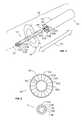
- FIG. 1is an exploded isometric view illustrating the components of a magnetic spring according to an embodiment of the present invention.
- FIG. 2shows axial views separately illustrating the stator and slider of the magnetic spring of FIG. 1 .
- FIG. 3illustrates a non-limiting example of a spatially modulated magnetic field pattern of regional magnetic orientation in a magnetic spring stator according to the present invention.
- FIG. 4shows axial views separately illustrating the stator and slider of a magnetic spring according to another embodiment of the present invention.
- FIG. 5illustrates a non-limiting example of a force curve for a magnetic spring according to an embodiment of the present invention.
- FIG. 6Ais an axial view illustrating a magnetic spring according to another embodiment of the present invention with a slider in a first azimuthal orientation.
- FIG. 6Bis an axial view illustrating the magnetic spring of FIG. 6A , with the slider in a second azimuthal orientation.
- FIG. 7illustrates a non-limiting example of two respective force curves for the magnetic spring of FIG. 6A and FIG. 6B in the two azimuthal orientations.
- FIG. 1illustrates the components and makeup of a magnetic spring 100 according to an embodiment of the present invention.
- a stator 101has a protective outer casing 103 and a thin low-friction inner bearing 105 around a recess 109 inside which a slider 111 fits and slides in and out in directions 115 along a longitudinal axis 117 .
- Between casing 103 and bearing 105is a magnetic material having a spatially modulated magnetic field pattern of magnetic regions, such as in representative regions 107 A, 107 B, 107 C, 107 D, and 107 E.
- Spatially modulated magnetic field patterns of magnets and magnetic regionsare known in the art, and techniques of creating predetermined spatially modulated magnetic field patterns of magnetic regions are also known in the art. According to embodiments of the present invention, such techniques may be utilized to create spatially modulated magnetic field patterns of magnetic regions in the components of a magnetic spring as described herein.
- stator 101 and slider 111feature patterns which are spatially-modulated both axially and azimuthally.
- Slider 111contains a magnetic material, also having a spatially modulated magnetic field pattern of magnetic regions, such as in representative regions 113 A, 113 B, 113 C, 113 D, and 113 E.
- FIG. 2shows enlarged axial views of stator 101 and slider 111 .
- the magnetic interaction between the spatially modulated magnetic field pattern of magnetic regions in stator 101 and the spatially modulated magnetic field pattern of magnetic regions in slider 111give rise to an axial force between stator 101 and slider 111 , which is a function of the axial displacement of slider 111 relative to stator 101 .
- FIG. 3shows a non-limiting example of a spatially modulated magnetic field pattern of magnetic regions in representative regions 107 A, 107 B, 107 C, 107 D, and 107 E, according to an embodiment of the present invention.
- the arrows in the representative regions shown in FIG. 3represent the respective magnetic moment vectors of the regions, with the arrows pointing according to the common convention, from the respective south poles to the respective north poles.
- the term “spatially modulated magnetic field pattern”denotes that the specific pattern of magnetic orientations in the magnetic regions is according to a predetermined arrangement.
- slider 111may be mechanically free to be rotated inside stator 101 in directions 119 ( FIG. 1 ) to change azimuthal orientation.
- slider 111may be constrained to a particular range or set of values of azimuthal orientation.
- constraintsmay be imposed magnetically, by the particular spatially modulated magnetic field patterns of the magnetic regions; in other specific embodiments, constraints may be imposed mechanically, such as by a keyed channel, or by the geometry of the stator and slider.
- a prismatic geometry lacking continuous rotational symmetrycan be used.
- stator 401contains a spatially modulated magnetic field pattern of magnetic regions, such as in representative regions 407 A, 407 B, and 407 C; and slider 411 also contains a spatially modulated magnetic field pattern of magnetic regions, such as in representative regions 413 A, 413 B, and 413 C.
- the geometry of the slider and the stator recesscan be such that there is no rotational symmetry at all, in which case the slider-stator azimuthal angular alignment is fixed so long as the slider remains inserted in the stator. If the slider is removable from the stator, however, the azimuthal angular alignment can be changed by removal, reorientation, and re-insertion.
- FIG. 5illustrates a non-limiting example of a force curve 505 for a magnetic spring according to an embodiment of the present invention.
- Stator 101 and slider 111are mechanically free to undergo an axial movement relative to one another along axis 117 ( FIG. 1 ) over a predefined range in a direction 507 or in a direction 509 .
- Slider 111 and stator 101have a spatial relationship with a magnetic interaction between the spatially modulated magnetic field pattern of magnetic regions in slider 111 with the spatially modulated magnetic field pattern of magnetic regions in stator 101 .
- the magnetic interactionresults in axial force curve 505 , which is a function of the axial displacement of slider 111 relative to stator 101 .
- Axial force 505is plotted according to a force axis 501 against an axial displacement axis 503 .
- the precise form of force curve 505depends on the specific properties of the spatially modulated magnetic field patterns of magnetic regions.
- a portion 515exhibits a relatively constant force over a portion of the displacement range
- another portion 517exhibits a different relatively constant force over another portion of the displacement range.
- Embodiments of the present inventionprovide different force curves by having different spatially modulated magnetic field patterns of magnetic regions in the slider and/or stator.
- FIG. 6Ais an axial view illustrating a magnetic spring according to another embodiment of the present invention that provides different force curves in the same magnetic spring, which are selected by rotating the slider to different predetermined angular positions relative to the angular position of the stator.
- a stator 601has an index mark 609 in one angular position, and another index mark 617 in another angular position.
- a slider 611has an indicator 615 showing an azimuthal angular alignment with index mark 609 , so that representative magnetic regions 613 A, 613 B, and 613 C of slider 611 align with representative magnetic regions 607 A, 607 B, and 607 C, respectively, of stator 601 .
- FIG. 6Bis an axial view illustrating the magnetic spring of FIG.
- FIG. 7illustrates non-limiting examples of a force curve 711 corresponding to the slider-stator azimuthal angular displacement of FIG.
- a single magnetic spring according to this embodiment of the present inventioncan provide different spring characteristics for a particular application simply by rotating the slider to a different position relative to the stator. Since the rotation is relative to the slider, this embodiment can be used in a configuration where the slider has a fixed rotational position, and it is the stator which is rotated instead, to select the spring characteristics.
Landscapes
- Engineering & Computer Science (AREA)
- General Engineering & Computer Science (AREA)
- Mechanical Engineering (AREA)
- Reciprocating, Oscillating Or Vibrating Motors (AREA)
- Magnetic Bearings And Hydrostatic Bearings (AREA)
Abstract
Description
Claims (5)
Priority Applications (3)
| Application Number | Priority Date | Filing Date | Title |
|---|---|---|---|
| US13/527,740US9016446B2 (en) | 2012-06-20 | 2012-06-20 | High energy density magnetic springs using spatially modulated magnetic fields technology |
| DE201310211314DE102013211314A1 (en) | 2012-06-20 | 2013-06-17 | Multi-configurable magnetic spring with selectable properties |
| CN201310245936.6ACN103511528B (en) | 2012-06-20 | 2013-06-20 | What have an optional feature can the magnetic spring of multiple structure |
Applications Claiming Priority (1)
| Application Number | Priority Date | Filing Date | Title |
|---|---|---|---|
| US13/527,740US9016446B2 (en) | 2012-06-20 | 2012-06-20 | High energy density magnetic springs using spatially modulated magnetic fields technology |
Publications (2)
| Publication Number | Publication Date |
|---|---|
| US20130341137A1 US20130341137A1 (en) | 2013-12-26 |
| US9016446B2true US9016446B2 (en) | 2015-04-28 |
Family
ID=49713869
Family Applications (1)
| Application Number | Title | Priority Date | Filing Date |
|---|---|---|---|
| US13/527,740Expired - Fee RelatedUS9016446B2 (en) | 2012-06-20 | 2012-06-20 | High energy density magnetic springs using spatially modulated magnetic fields technology |
Country Status (3)
| Country | Link |
|---|---|
| US (1) | US9016446B2 (en) |
| CN (1) | CN103511528B (en) |
| DE (1) | DE102013211314A1 (en) |
Cited By (5)
| Publication number | Priority date | Publication date | Assignee | Title |
|---|---|---|---|---|
| US20170138434A1 (en)* | 2015-11-18 | 2017-05-18 | Toyota Motor Engineering & Manufacturing North America, Inc. | Magnetic field activated powertrain mount |
| NL2020783B1 (en)* | 2018-04-18 | 2019-10-24 | Flanders Make Vzw | Magnetic spring |
| US20200332857A1 (en)* | 2019-04-22 | 2020-10-22 | Invetech, Inc. | Adjustable Magnetic Counterbalance |
| US20210054897A1 (en)* | 2019-08-19 | 2021-02-25 | Portland State University | Variable stiffness magnetic spring |
| US20230151868A1 (en)* | 2021-10-14 | 2023-05-18 | Portland State University | Rotary and linear adjustable stiffness magnetic springs |
Families Citing this family (24)
| Publication number | Priority date | Publication date | Assignee | Title |
|---|---|---|---|---|
| US7800471B2 (en) | 2008-04-04 | 2010-09-21 | Cedar Ridge Research, Llc | Field emission system and method |
| US8576036B2 (en) | 2010-12-10 | 2013-11-05 | Correlated Magnetics Research, Llc | System and method for affecting flux of multi-pole magnetic structures |
| US8760250B2 (en) | 2009-06-02 | 2014-06-24 | Correlated Magnetics Rsearch, LLC. | System and method for energy generation |
| US9371923B2 (en) | 2008-04-04 | 2016-06-21 | Correlated Magnetics Research, Llc | Magnetic valve assembly |
| US8816805B2 (en) | 2008-04-04 | 2014-08-26 | Correlated Magnetics Research, Llc. | Magnetic structure production |
| US9105380B2 (en) | 2008-04-04 | 2015-08-11 | Correlated Magnetics Research, Llc. | Magnetic attachment system |
| US8179219B2 (en) | 2008-04-04 | 2012-05-15 | Correlated Magnetics Research, Llc | Field emission system and method |
| US9202615B2 (en) | 2012-02-28 | 2015-12-01 | Correlated Magnetics Research, Llc | System for detaching a magnetic structure from a ferromagnetic material |
| US9202616B2 (en) | 2009-06-02 | 2015-12-01 | Correlated Magnetics Research, Llc | Intelligent magnetic system |
| US8174347B2 (en) | 2010-07-12 | 2012-05-08 | Correlated Magnetics Research, Llc | Multilevel correlated magnetic system and method for using the same |
| US9275783B2 (en) | 2012-10-15 | 2016-03-01 | Correlated Magnetics Research, Llc. | System and method for demagnetization of a magnetic structure region |
| US9404776B2 (en) | 2009-06-02 | 2016-08-02 | Correlated Magnetics Research, Llc. | System and method for tailoring polarity transitions of magnetic structures |
| US8704626B2 (en) | 2010-05-10 | 2014-04-22 | Correlated Magnetics Research, Llc | System and method for moving an object |
| US9257219B2 (en) | 2012-08-06 | 2016-02-09 | Correlated Magnetics Research, Llc. | System and method for magnetization |
| US9711268B2 (en) | 2009-09-22 | 2017-07-18 | Correlated Magnetics Research, Llc | System and method for tailoring magnetic forces |
| US8702437B2 (en) | 2011-03-24 | 2014-04-22 | Correlated Magnetics Research, Llc | Electrical adapter system |
| US9219403B2 (en) | 2011-09-06 | 2015-12-22 | Correlated Magnetics Research, Llc | Magnetic shear force transfer device |
| US9245677B2 (en) | 2012-08-06 | 2016-01-26 | Correlated Magnetics Research, Llc. | System for concentrating and controlling magnetic flux of a multi-pole magnetic structure |
| US9298281B2 (en) | 2012-12-27 | 2016-03-29 | Correlated Magnetics Research, Llc. | Magnetic vector sensor positioning and communications system |
| CN104930099B (en)* | 2015-06-26 | 2017-03-08 | 中国科学院合肥物质科学研究院 | Bidirectional rotary damper based on cylindrical magnet pair and its control method |
| WO2019185196A1 (en)* | 2018-03-30 | 2019-10-03 | Esm Energie- Und Schwingungstechnik Mitsch Gmbh | Linear magnetic spring and use in vibration dampers |
| CN112922990B (en)* | 2021-01-19 | 2022-09-09 | 上海隐冠半导体技术有限公司 | Magnetic spring device |
| CN115045941A (en)* | 2022-05-25 | 2022-09-13 | 横川机器人(深圳)有限公司 | Constant force spring, operation method and mechanical equipment |
| WO2024249999A1 (en)* | 2023-06-02 | 2024-12-05 | Brane Audio, LLC | Loudspeakers and methods of use thereof |
Citations (10)
| Publication number | Priority date | Publication date | Assignee | Title |
|---|---|---|---|---|
| US5159219A (en)* | 1991-05-16 | 1992-10-27 | University Of Houston-University Park | Opposed-magnet bearing with interposed superconductor |
| US5216308A (en)* | 1989-05-25 | 1993-06-01 | Avcon-Advanced Controls Technology, Inc. | Magnetic bearing structure providing radial, axial and moment load bearing support for a rotatable shaft |
| US5994809A (en)* | 1996-12-17 | 1999-11-30 | U.S. Philips Corporation | Magnetic drive arrangement |
| US20100282528A1 (en)* | 2009-05-05 | 2010-11-11 | Yoram Palti | Electro-Mechanical Battery |
| US20110121674A1 (en)* | 2008-08-08 | 2011-05-26 | Rolls-Royce Plc | Magnetic gear arrangement |
| US20120119463A1 (en)* | 2006-07-05 | 2012-05-17 | Johannes Jacobus Hubertus Paulides | Magnetic Spring, A Spring And Damper Assembly, And A Vehicle Including The Spring |
| US20120193179A1 (en)* | 2009-05-26 | 2012-08-02 | Bart Ludo Jozef Gysen | Electromagnetic actuator with integrated passive damper |
| US20120279345A1 (en)* | 2009-11-25 | 2012-11-08 | Commissariat A L'energie Atomique Et Aux Energies | Translatably and rotatably semi-active device |
| US20130002075A1 (en)* | 2010-01-19 | 2013-01-03 | Rolls-Royce Plc | Magnetic gear arrangement |
| US20130033136A1 (en)* | 2011-08-03 | 2013-02-07 | Mcmullen Patrick T | Electric Machine with Inner Magnet Hub |
Family Cites Families (8)
| Publication number | Priority date | Publication date | Assignee | Title |
|---|---|---|---|---|
| DE8222808U1 (en)* | 1982-08-12 | 1982-12-23 | Siemens AG, 1000 Berlin und 8000 München | Inductive spring and damper device |
| JPH01199029A (en)* | 1988-01-30 | 1989-08-10 | Kubota Ltd | Magnet spring |
| DE3817056A1 (en)* | 1988-05-19 | 1989-11-30 | Bosch Gmbh Robert | MAGNETIC SPRING |
| JPH07113440A (en)* | 1993-10-18 | 1995-05-02 | Mitsubishi Heavy Ind Ltd | Electromagnetic damper |
| DE10306500A1 (en)* | 2003-02-17 | 2004-08-26 | Bayerische Motoren Werke Ag | Wheel suspension especially active wheel suspension of vehicle uses electric linear motor that works as permanent excited synchronous motor and whose rotor is built by electrical coils |
| JP4293876B2 (en)* | 2003-10-01 | 2009-07-08 | 川崎重工業株式会社 | Electromagnetic actuator for vibration control |
| CN201065907Y (en)* | 2007-06-19 | 2008-05-28 | 刘新广 | Magnetic force shock-absorber |
| CN102182778A (en)* | 2011-03-10 | 2011-09-14 | 喜临门家具股份有限公司 | Magnetic force spring |
- 2012
- 2012-06-20USUS13/527,740patent/US9016446B2/ennot_activeExpired - Fee Related
- 2013
- 2013-06-17DEDE201310211314patent/DE102013211314A1/ennot_activeCeased
- 2013-06-20CNCN201310245936.6Apatent/CN103511528B/ennot_activeExpired - Fee Related
Patent Citations (10)
| Publication number | Priority date | Publication date | Assignee | Title |
|---|---|---|---|---|
| US5216308A (en)* | 1989-05-25 | 1993-06-01 | Avcon-Advanced Controls Technology, Inc. | Magnetic bearing structure providing radial, axial and moment load bearing support for a rotatable shaft |
| US5159219A (en)* | 1991-05-16 | 1992-10-27 | University Of Houston-University Park | Opposed-magnet bearing with interposed superconductor |
| US5994809A (en)* | 1996-12-17 | 1999-11-30 | U.S. Philips Corporation | Magnetic drive arrangement |
| US20120119463A1 (en)* | 2006-07-05 | 2012-05-17 | Johannes Jacobus Hubertus Paulides | Magnetic Spring, A Spring And Damper Assembly, And A Vehicle Including The Spring |
| US20110121674A1 (en)* | 2008-08-08 | 2011-05-26 | Rolls-Royce Plc | Magnetic gear arrangement |
| US20100282528A1 (en)* | 2009-05-05 | 2010-11-11 | Yoram Palti | Electro-Mechanical Battery |
| US20120193179A1 (en)* | 2009-05-26 | 2012-08-02 | Bart Ludo Jozef Gysen | Electromagnetic actuator with integrated passive damper |
| US20120279345A1 (en)* | 2009-11-25 | 2012-11-08 | Commissariat A L'energie Atomique Et Aux Energies | Translatably and rotatably semi-active device |
| US20130002075A1 (en)* | 2010-01-19 | 2013-01-03 | Rolls-Royce Plc | Magnetic gear arrangement |
| US20130033136A1 (en)* | 2011-08-03 | 2013-02-07 | Mcmullen Patrick T | Electric Machine with Inner Magnet Hub |
Cited By (10)
| Publication number | Priority date | Publication date | Assignee | Title |
|---|---|---|---|---|
| US20170138434A1 (en)* | 2015-11-18 | 2017-05-18 | Toyota Motor Engineering & Manufacturing North America, Inc. | Magnetic field activated powertrain mount |
| US9874264B2 (en)* | 2015-11-18 | 2018-01-23 | Toyota Motor Engineering & Manufacturing North America, Inc. | Magnetic field activated powertrain mount |
| NL2020783B1 (en)* | 2018-04-18 | 2019-10-24 | Flanders Make Vzw | Magnetic spring |
| WO2019201907A1 (en)* | 2018-04-18 | 2019-10-24 | Flanders Make Vzw | Magnetic spring |
| US20200332857A1 (en)* | 2019-04-22 | 2020-10-22 | Invetech, Inc. | Adjustable Magnetic Counterbalance |
| US11852212B2 (en)* | 2019-04-22 | 2023-12-26 | Invetech, Inc. | Adjustable magnetic counterbalance |
| US20210054897A1 (en)* | 2019-08-19 | 2021-02-25 | Portland State University | Variable stiffness magnetic spring |
| US11879516B2 (en)* | 2019-08-19 | 2024-01-23 | Portland State University | Variable stiffness magnetic spring |
| US20230151868A1 (en)* | 2021-10-14 | 2023-05-18 | Portland State University | Rotary and linear adjustable stiffness magnetic springs |
| US12372132B2 (en)* | 2021-10-14 | 2025-07-29 | Portland State University | Rotary and linear adjustable stiffness magnetic springs |
Also Published As
| Publication number | Publication date |
|---|---|
| CN103511528B (en) | 2016-02-10 |
| US20130341137A1 (en) | 2013-12-26 |
| CN103511528A (en) | 2014-01-15 |
| DE102013211314A1 (en) | 2013-12-24 |
Similar Documents
| Publication | Publication Date | Title |
|---|---|---|
| US9016446B2 (en) | High energy density magnetic springs using spatially modulated magnetic fields technology | |
| KR101173519B1 (en) | Position sensor utilizing a linear hall-effect sensor, having a magnet arrangement for an increased linearity | |
| CN106402159B (en) | A kind of permanent magnetism off-set magnetic suspension shaft | |
| US9103423B2 (en) | Linear actuator | |
| JP2015019546A (en) | Axial gap type permanent magnet rotating electric machine and manufacturing method thereof | |
| JP2015144537A (en) | Resistance generating device | |
| AU2016250494B2 (en) | Electric current generating turbine | |
| US10284065B2 (en) | Horizontal linear vibration motor | |
| JP6406531B2 (en) | Magnetic position detector | |
| JP2015143450A (en) | Resistance generator for use in driving device | |
| US20160087515A1 (en) | Linear-rotary actuator | |
| JP2007259531A (en) | Rotating electric machine | |
| CN109253199A (en) | damper | |
| US9977456B2 (en) | Magnetic detenting configuration for custom encoder | |
| JP7016591B2 (en) | Sealing device | |
| US9742258B2 (en) | Rotational-linear motion converter | |
| CN207835191U (en) | A kind of rotor using Halbach magnet ring | |
| JP2012019613A (en) | Linear motor | |
| CN117940743A (en) | Position encoder based on Halbach magnetic element | |
| JP6110165B2 (en) | Linear motor | |
| US10424978B2 (en) | Rotating electrical machine comprising stator core, and machine tool comprising the same | |
| KR20160033630A (en) | Direct acting rotation actuator | |
| US10910921B2 (en) | Device for detecting position of rotor, and motor comprising same | |
| JPWO2014109220A1 (en) | Rotating electric machine | |
| JP7349160B2 (en) | Magnetic power transmission structure |
Legal Events
| Date | Code | Title | Description |
|---|---|---|---|
| AS | Assignment | Owner name:GM GLOBAL TECHNOLOGY OPERATIONS LLC, MICHIGAN Free format text:ASSIGNMENT OF ASSIGNORS INTEREST;ASSIGNORS:MANKAME, NILESH D.;KRAJEWSKI, PAUL E.;MATHIEU, ROY J.;AND OTHERS;SIGNING DATES FROM 20120430 TO 20120614;REEL/FRAME:028408/0953 | |
| AS | Assignment | Owner name:WILMINGTON TRUST COMPANY, DELAWARE Free format text:SECURITY AGREEMENT;ASSIGNOR:GM GLOBAL TECHNOLOGY OPERATIONS LLC;REEL/FRAME:030694/0500 Effective date:20101027 | |
| AS | Assignment | Owner name:GM GLOBAL TECHNOLOGY OPERATIONS LLC, MICHIGAN Free format text:RELEASE BY SECURED PARTY;ASSIGNOR:WILMINGTON TRUST COMPANY;REEL/FRAME:034287/0415 Effective date:20141017 | |
| FEPP | Fee payment procedure | Free format text:PAYOR NUMBER ASSIGNED (ORIGINAL EVENT CODE: ASPN); ENTITY STATUS OF PATENT OWNER: LARGE ENTITY | |
| STCF | Information on status: patent grant | Free format text:PATENTED CASE | |
| MAFP | Maintenance fee payment | Free format text:PAYMENT OF MAINTENANCE FEE, 4TH YEAR, LARGE ENTITY (ORIGINAL EVENT CODE: M1551); ENTITY STATUS OF PATENT OWNER: LARGE ENTITY Year of fee payment:4 | |
| FEPP | Fee payment procedure | Free format text:MAINTENANCE FEE REMINDER MAILED (ORIGINAL EVENT CODE: REM.); ENTITY STATUS OF PATENT OWNER: LARGE ENTITY | |
| LAPS | Lapse for failure to pay maintenance fees | Free format text:PATENT EXPIRED FOR FAILURE TO PAY MAINTENANCE FEES (ORIGINAL EVENT CODE: EXP.); ENTITY STATUS OF PATENT OWNER: LARGE ENTITY | |
| STCH | Information on status: patent discontinuation | Free format text:PATENT EXPIRED DUE TO NONPAYMENT OF MAINTENANCE FEES UNDER 37 CFR 1.362 | |
| FP | Lapsed due to failure to pay maintenance fee | Effective date:20230428 |