US9015924B2 - Method of making a covering panel with bevelled edges having varying cross-section - Google Patents
Method of making a covering panel with bevelled edges having varying cross-sectionDownload PDFInfo
- Publication number
- US9015924B2 US9015924B2US13/528,415US201213528415AUS9015924B2US 9015924 B2US9015924 B2US 9015924B2US 201213528415 AUS201213528415 AUS 201213528415AUS 9015924 B2US9015924 B2US 9015924B2
- Authority
- US
- United States
- Prior art keywords
- edge
- panel
- milling tool
- lowered part
- machining
- Prior art date
- Legal status (The legal status is an assumption and is not a legal conclusion. Google has not performed a legal analysis and makes no representation as to the accuracy of the status listed.)
- Active, expires
Links
Images


Classifications
- E—FIXED CONSTRUCTIONS
- E04—BUILDING
- E04F—FINISHING WORK ON BUILDINGS, e.g. STAIRS, FLOORS
- E04F15/00—Flooring
- E04F15/02—Flooring or floor layers composed of a number of similar elements
- B—PERFORMING OPERATIONS; TRANSPORTING
- B44—DECORATIVE ARTS
- B44C—PRODUCING DECORATIVE EFFECTS; MOSAICS; TARSIA WORK; PAPERHANGING
- B44C5/00—Processes for producing special ornamental bodies
- B44C5/04—Ornamental plaques, e.g. decorative panels, decorative veneers
- E—FIXED CONSTRUCTIONS
- E04—BUILDING
- E04F—FINISHING WORK ON BUILDINGS, e.g. STAIRS, FLOORS
- E04F15/00—Flooring
- E04F15/02—Flooring or floor layers composed of a number of similar elements
- E04F15/02005—Construction of joints, e.g. dividing strips
- E04F15/02011—Construction of joints, e.g. dividing strips with joint fillings integrated in the flooring elements
- E—FIXED CONSTRUCTIONS
- E04—BUILDING
- E04F—FINISHING WORK ON BUILDINGS, e.g. STAIRS, FLOORS
- E04F15/00—Flooring
- E04F15/02—Flooring or floor layers composed of a number of similar elements
- E04F15/02005—Construction of joints, e.g. dividing strips
- E04F15/02016—Construction of joints, e.g. dividing strips with sealing elements between flooring elements
- E—FIXED CONSTRUCTIONS
- E04—BUILDING
- E04F—FINISHING WORK ON BUILDINGS, e.g. STAIRS, FLOORS
- E04F15/00—Flooring
- E04F15/02—Flooring or floor layers composed of a number of similar elements
- E04F15/02005—Construction of joints, e.g. dividing strips
- E04F15/02033—Joints with beveled or recessed upper edges
- E—FIXED CONSTRUCTIONS
- E04—BUILDING
- E04F—FINISHING WORK ON BUILDINGS, e.g. STAIRS, FLOORS
- E04F15/00—Flooring
- E04F15/02—Flooring or floor layers composed of a number of similar elements
- E04F15/02005—Construction of joints, e.g. dividing strips
- E—FIXED CONSTRUCTIONS
- E04—BUILDING
- E04F—FINISHING WORK ON BUILDINGS, e.g. STAIRS, FLOORS
- E04F15/00—Flooring
- E04F15/02—Flooring or floor layers composed of a number of similar elements
- E04F15/02038—Flooring or floor layers composed of a number of similar elements characterised by tongue and groove connections between neighbouring flooring elements
- E—FIXED CONSTRUCTIONS
- E04—BUILDING
- E04F—FINISHING WORK ON BUILDINGS, e.g. STAIRS, FLOORS
- E04F15/00—Flooring
- E04F15/02—Flooring or floor layers composed of a number of similar elements
- E04F15/04—Flooring or floor layers composed of a number of similar elements only of wood or with a top layer of wood, e.g. with wooden or metal connecting members
- E—FIXED CONSTRUCTIONS
- E04—BUILDING
- E04F—FINISHING WORK ON BUILDINGS, e.g. STAIRS, FLOORS
- E04F2201/00—Joining sheets or plates or panels
- E04F2201/01—Joining sheets, plates or panels with edges in abutting relationship
- E04F2201/0153—Joining sheets, plates or panels with edges in abutting relationship by rotating the sheets, plates or panels around an axis which is parallel to the abutting edges, possibly combined with a sliding movement
- Y—GENERAL TAGGING OF NEW TECHNOLOGICAL DEVELOPMENTS; GENERAL TAGGING OF CROSS-SECTIONAL TECHNOLOGIES SPANNING OVER SEVERAL SECTIONS OF THE IPC; TECHNICAL SUBJECTS COVERED BY FORMER USPC CROSS-REFERENCE ART COLLECTIONS [XRACs] AND DIGESTS
- Y10—TECHNICAL SUBJECTS COVERED BY FORMER USPC
- Y10T—TECHNICAL SUBJECTS COVERED BY FORMER US CLASSIFICATION
- Y10T29/00—Metal working
- Y10T29/49—Method of mechanical manufacture
- Y10T29/49826—Assembling or joining
- Y10T29/49885—Assembling or joining with coating before or during assembling
- Y—GENERAL TAGGING OF NEW TECHNOLOGICAL DEVELOPMENTS; GENERAL TAGGING OF CROSS-SECTIONAL TECHNOLOGIES SPANNING OVER SEVERAL SECTIONS OF THE IPC; TECHNICAL SUBJECTS COVERED BY FORMER USPC CROSS-REFERENCE ART COLLECTIONS [XRACs] AND DIGESTS
- Y10—TECHNICAL SUBJECTS COVERED BY FORMER USPC
- Y10T—TECHNICAL SUBJECTS COVERED BY FORMER US CLASSIFICATION
- Y10T29/00—Metal working
- Y10T29/49—Method of mechanical manufacture
- Y10T29/49995—Shaping one-piece blank by removing material
- Y—GENERAL TAGGING OF NEW TECHNOLOGICAL DEVELOPMENTS; GENERAL TAGGING OF CROSS-SECTIONAL TECHNOLOGIES SPANNING OVER SEVERAL SECTIONS OF THE IPC; TECHNICAL SUBJECTS COVERED BY FORMER USPC CROSS-REFERENCE ART COLLECTIONS [XRACs] AND DIGESTS
- Y10—TECHNICAL SUBJECTS COVERED BY FORMER USPC
- Y10T—TECHNICAL SUBJECTS COVERED BY FORMER US CLASSIFICATION
- Y10T409/00—Gear cutting, milling, or planing
- Y10T409/30—Milling
- Y10T409/30868—Work support
Definitions
- the inventionrelates to a panel for use in an assembly of panels attached to each other to form a covering, comprising an upper surface and a lower surface each extending within a different main plane, and at least an edge between these surfaces comprising a coupling to couple the panel to of another panel, wherein the upper surface includes a lowered part at said edge of the panel.
- the inventionalso relates to a method of making such panels.
- Such panelsare known in various embodiments, for example in the form of laminate floor panels. Such panels are made on a wood basis and have a decorating layer mostly to imitate natural panels made from wood or other natural materials.
- An aspect of the inventionprovides a panel of which the cross-section of the lowered part, perpendicular to the edge of the panel, varies along the edge.
- the lowered parthas a non-planar structure along the edge, which improves the natural appearance of a panel.
- the advantageis that the panels according to the invention provide a better imitation of natural panels than those having a flat lowered part.
- the cross-section of the lowered partmay vary along the length of the edge in an irregular, preferably random manner, for example a rustical design. This improves the natural appearance of a panel still further.
- the lowered partmay have an extreme edge which is intended to be positioned against an extreme edge of an adjacent panel, which extreme edge has a constant position within each cross-section.
- the extreme edge of each of the panels in an assembly of panelscan be coupled to each other to form the covering such that the covering is sealed between adjacent panels at the extreme edge. This prevents leakage of water or the like between panels.
- this featurehas the advantage that it avoids exposing of a portion of the edge of the panel if the extreme edge of adjacent panels had varying positions at different locations with respect to each other along the edge.
- the upper surface of the panelmay be provided with a surface decoration, whereas the lowered part may be provided with a surface finishing. This provides the opportunity to apply the production method of providing the surface decoration to the panel such as known in the art, whereas the lowered part can be finished in a separate process.
- the inventionprovides a panel for use in an assembly of panels attached to each other to form a covering, comprising an upper surface and a lower surface each extending within a different main plane, and at least an edge between these surfaces comprising a coupling to couple the panel to a coupling of another panel, wherein the upper surface includes a lowered part at said edge of the panel, the lowered part crossing the main plane of the upper surface along a first line and crossing an extreme edge of the panel which is intended to be positioned against an extreme edge of an adjacent panel along a second line, wherein the extent of the first line deviates from the extent of the second line.
- the first line between the upper surface and the lowered partmay be used to improve the natural appearance of a panel.
- the inventionalso provides a method of making a panel for use in a covering, including the steps of:
- a panelcomprising an upper surface and a lower surface each extending within a different main plane, and at least an edge between these surfaces
- edgeis machined such that the lowered part is provided with a cross-section perpendicular to the edge of the panel which varies along the edge of the panel.
- This methodmay provide panels having the advantages as mentioned hereinbefore.
- the lowered partmay be provided with a coating, such as a foil or paint, which has the benefit of protecting the panels against dirt, water and the like. For esthetical reasons it may be of a rustical design, for example.
- the upper surface of the panelis provided with a surface finishing before the coating is provided on the lowered part, wherein the finished upper surface is provided with an anti-adhesive before the lowered part is coated, and any coating which is applied on the anti-adhesive is removed together with the anti-adhesive, for example by brushing.
- the advantage of these stepsis that they simplify the method of making panels according to the invention. Since the cross-section of the lowered part along the edge varies, the width of the lowered part as seen in a direction along the edge of the panel may vary. As a consequence, the width of the foil or the amount of paint may vary along the edge of the panel.
- the width of the foil or paint spraymay be locally larger than the width of the lowered part as mentioned above, because excessive foil or paint can be removed easily from the upper surface next to the lowered part, for example by brushing.
- the width of the foil or paint spraymay be locally larger than the width of the lowered part as mentioned above, because excessive foil or paint can be removed easily from the upper surface next to the lowered part, for example by brushing.
- the edgeis machined by means of a milling tool, which is either moved in a direction towards and away from the edge during milling of the edge, or the milling is effected by means of a rotary milling tool having teeth around its circumference which have a varying distance from the rotary centre of the tool.
- a milling toolwhich is either moved in a direction towards and away from the edge during milling of the edge, or the milling is effected by means of a rotary milling tool having teeth around its circumference which have a varying distance from the rotary centre of the tool.
- FIG. 1is a very schematic perspective plan view of two adjacent panels according to the invention.
- FIG. 2is a larger-scale perspective cross-section along the line II-II in FIG. 1 .
- FIG. 2 ais a very schematic side view of an alternative embodiment of a milling tool for machining the edge of a panel to form the lowered part.
- FIG. 3 ais a very schematic side view of a panel, illustrating an alternative machining step, showing the panel upside down.
- FIG. 3 bis a smaller-scale view as shown in FIG. 2 , illustrating adjacent panels which are manufactured according to the alternative machining step as illustrated in FIG. 3 a.
- FIG. 3 cis a view as shown in FIG. 2 , illustrating adjacent panels which are manufactured according to still another alternative machining step.
- FIGS. 4 a - 4 care very schematic sectional views of two panels in different manufacturing steps, showing the panels upside down.
- FIGS. 5 a - 5 bare very schematic sectional views of a panel and a press tool, illustrating the process of fixing a foil to the lowered part.
- FIG. 6 ais a very schematic side view of an apparatus for providing and adhering foils on a lowered part of a panel.
- FIG. 6 bis a view which is partly similar to FIG. 6 a , in which the way of pressing two different portions of a panel is illustrated.
- FIG. 6 cis a very schematic side view of an apparatus nearly similar to that shown in FIG. 6 b , but including a single belt.
- FIG. 6 dis a very schematic side view of an apparatus nearly similar to that shown in FIG. 6 c , but including a shorter single belt as seen in a direction of movement, illustrating the way of pressing two different portions of a panel synchronously.
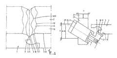
- FIG. 7is a very schematic side view of an embodiment of a milling tool for machining the edge of a panel to form the lowered part.
- FIG. 8is a very schematic side view of an alternative embodiment of a milling tool for machining the edge of a panel to form the lowered part.
- FIG. 1illustrates two adjacent panels 1 of one embodiment of the panel according to the invention.
- the panels 1 as shown in FIG. 1are attached to each other and may be part of a covering when a plurality of panels are attached to each other in this way.
- the panelswill be rectangular, either square or elongated or in between. However, other shapes are conceivable.
- FIG. 2illustrates a cross-section of the assembly of the panels 1 as shown in FIG. 1 on a larger scale in more detail.
- Each panel 1comprises an upper surface 2 and a lower surface 3 . These surfaces 2 , 3 each extend within different main planes. In the embodiment as shown in FIG. 2 , the main portions of the upper surface 2 and lower surface 3 are parallel to each other and spaced in Y direction. The upper and lower surfaces 2 , 3 are substantially flat surfaces.
- the panelcomprises an edge 4 between both surfaces.
- the edge 4is provided with a coupling to couple the panel 1 to a coupling of the adjacent panel 1 , such as shown in FIG. 2 .
- the couplingis well-known in the art, for example formed by a tongue 5 and groove 6 and are not part of the present invention. Of course, it is possible to provide the panel 1 with various kinds of couplings and locking devices for attaching the panels 1 to each other.
- the upper surface 2includes a lowered part 7 on at least one, but preferably all edges 4 of the panel.
- FIG. 2shows that the upper surface 2 comprises a substantially flat surface portion 8 and the lowered part 7 .
- the lowered part 7is located below the flat surface portion 8 of the upper surface 7 as seen in Y direction.
- the upper surface 2 of the panel 1is provided with a surface decoration which imitates natural materials, such as wood.
- This surface decorationmay include a laminate of paper layers impregnated with resin.
- the remaining part of the panel 1 below the upper surface 2may include a core comprising one or more layers of MDF, HDF, HTSP, PVC, composites or the like, and possibly a balancing layer.
- the cross-section of the lowered part 7perpendicular to the edge of the panel, varies along the edge 4 .
- the edge 4extends in Z direction.
- the lowered part 7has a non planar structure as seen along the edge 4 . This provides a natural appearance of the panels 1 .
- the embodiment of the panel 1 as shown in FIG. 2has a lowered part 7 of which the cross-section varies in an irregular manner. Preferably, it varies in a random manner so as to provide a most natural look of the panel 1 .
- the lowered part 7has an extreme edge 9 , which is positioned against an extreme edge 9 of the adjacent panel 1 .
- the extreme edge 9is straight and therefore has the same position within each cross-section so as to obtain an appropriate sealing between adjacent panels 1 . It can be seen in FIG. 2 that the extreme edge 9 has a fixed position with respect to the lower surface 3 since the extreme edge 9 extends parallel to the lower surface 3 and the upper surface 2 , whereas the rest of the lowered part 7 varies in a random manner.
- the lowered part 7has an inclined extent as seen from the extreme edge 9 to the upper surface 2 .
- a lower section 10 of the V-groove, which is adjacent to the extreme edge 9has a planar shape and a varying cross-section along the edge 4 .
- An upper section 11 of the lowered part 7which is located between the lower section 10 and the flat surface portion 8 of the upper surface 2 , has a varying cross-section along the edge 4 .
- the angle of the lower section 10 with respect to the upper surface 2is larger than the angle of the upper section 11 with respect to the upper surface 2 , for example 35-85° and 15-40°, respectively, but other angles are also possible, of course.
- the width of the lowered part 7 in the X, Y plane along the edge 4may vary around 2 mm, for example, but other dimensions are conceivable, of course.
- FIG. 2also shows that the lowered part 7 crosses the upper surface 2 in a first line 12 , while a line 12 A separates the lower section 10 from the upper section 11 .
- the extreme edge 9forms a second line. It can be seen that lines 12 and 12 A deviate from that of the extreme edge 9 so as to form the desired non-planar structure of the lowered part 7 .
- the panel 1such as described hereinbefore can be made by the following steps: machining the edge 4 to form a coupling 5 , 6 ; providing the upper surface 2 with a lowered part 7 at the edge 4 ; and machining the edge 4 such that the lowered part 7 is provided with a varying cross-section perpendicular to the edge 4 of the panel 1 .
- the structure of the lowered part 7 in FIG. 2can be obtained by performing the following steps: first machining the flat lower section 10 by passing the panel 1 along a milling tool which has a fixed position with respect to the passing panel 1 , then passing the panel 1 along a milling tool which is moved in a direction towards and from the panel 1 so as to form the upper section 11 .
- One way of moving the milling toolis by moving it rectilinearly in X and/or Y-direction. This can be done by moving the tool through a motor (induction, linear etc.), pneumatically, hydraulically, mechanically in a controlled (random) manner.
- a motorinduction, linear etc.
- piezo electric elements or actuators or a linear motorin combination with a magnet which may be supported by a resilient member.
- one or more piezo elementscan be mounted between a machine support and the motor for moving the tool(s) in one or more directions. If more than one piezo element is used, these elements can be used in parallel or in series. FIG.
- FIG. 2 ashows an arrangement including a milling tool 21 attached to a motor 24 which is mounted on a support 25 and 26 which are each movable in directions perpendicular to each other.
- Each of the supportsis connected to a piezo electric element 27 , 28 , respectively which are mounted to a fixed base.
- the fixed base for element 27may also be formed by support 26 , so as to allow independent movements of the supports 25 and 26 in X and Y direction to create the desired shape of the lowered part 7 of the panel edge (in this case the upper part 11 thereof) when the milling tool 21 and the lowered part 7 are moved along each other.
- the lowered part 7can also be made in a single machining step. This is illustrated in FIG. 3 a .
- the lowered part 7is made by the milling tool 21 , which has a fixed position with respect to the position of the extreme edge 9 of the panel 1 .
- the milling tool 21can be swivelled about the extreme edge 9 such as shown by the double-headed arrow in FIG. 3 a .
- This alternative machining methodresults in panels having a lowered part 7 which has a non-planar structure between the first line 12 and the extreme edge 9 which has maintained its original shape, in this case a straight line.
- This machining methodresults in a panel 1 such as illustrated in FIG. 3 b.
- the piezo electric elementsmay also be used to create the swivel movement of the milling tool by placing the element(s) in an appropriate manner with respect to the milling tool or motor for actuating it.
- the upper surface 2 of a large plate of which panels 1 will be sawn off later onis initially provided with a surface decoration 13 before the panels 1 are sawn off.
- the lowered part 7is preferably provided with a surface finishing, such as a coating 14 comprising a foil 14 a or paint. This protects the material of the panel 1 against dirt and liquids or the like which might permeate into the panel 1 . It also provides the lowered part 7 with a color or decoration which is adapted to the decoration of the upper surface of the panel.
- the required amount of coating 14 or paint per unit of length along the edge 4 to be provided to the lowered part 7varies along the edge 4 , as well.
- the surface finishingcan be provided onto the upper surface 2 before the coating 14 is provided onto the lowered part 7 , whereas the finished upper surface 2 is provided with an anti-adhesive before the lowered part 7 is coated.
- a part of the coating 14may have been provided onto the upper surface 2 next to the lowered part 7 (the flat surface portion 8 ) which was already covered by the anti-adhesive.
- the remaining coating 14 on the upper surface 2can be easily removed from the upper surface 2 together with the anti-adhesive by brushing, for example.
- the anti-adhesiveis provided onto the upper surface 2 before machining the edge to form the lowered part 7 , because in this case the lowered part 7 is automatically made free of anti-adhesive during machining, whereas the flat surface portion 8 remains covered with the anti-adhesive.
- FIG. 4 ashows that the upper surfaces 2 of two panels 1 are covered by anti-adhesive near the edges before machining the edges 4 and forming the lowered part 7 (note that the panels are shown upside down in FIG. 4 ).
- the anti-adhesivecan be provided onto the upper surface 2 by using a spraying apparatus 15 .
- FIG. 4 billustrates the panels 1 after the coupling 5 , 6 and the lowered part 7 have been provided.
- FIG. 4 cillustrates the process of providing a foil 14 a as a coating 14 onto the lowered part 7 .
- FIGS. 5 a and 5 billustrate the process of providing a foil 14 a to the lowered surface 7 in more detail.
- FIG. 5 aillustrates the process of pressing the foil 14 a onto the panel 1 by two separate pressing tools 15 behind each other as seen in the direction along the edge 4 .
- Each of the pressing tools 15have substantially flat pressing surfaces 16 , which can be angled with respect to each other so as to create a pressing surface 16 corresponding to the shape of the lower part 7 .
- FIG. 5 bshows the process of pressing the foil 14 a onto the panel 1 by a single pressing tool 15 which has a deformable pressing surface 16 which adapts to the varying shape of the lowered part 7 .
- FIG. 6 ais a very schematic side view of an apparatus for providing a foil on a lowered part 7 of a panel 1 .
- a foil strip 14 ais supplied from the left side by a roller 17 comprising a foil strip 14 a .
- the foil strip 14 ahas a width of 8-10 mm, for example, but other dimensions are conceivable.
- the panels 1are also supplied from the left side (not shown) and are conveyed from left to right at the same speed as the speed of the foil strip 14 a .
- FIG. 6 aalso shows that the apparatus comprises pressing belts 18 and pressing rollers 19 which press the belt 18 against the foil 14 a onto the lowered part 7 of the panel 1 .
- the apparatusalso comprises heating elements 20 to support an adhering process of the foil strip 14 a to the panel 1 .
- the heating elements 20are able to keep the temperature of the foil at a constant level during the adhering process.
- FIG. 6 ashows two belts for the case that the lowered part 7 is provided with a lower section 10 and an upper section 11 each having different angles with respect to the upper surface 2 , such as illustrated in FIG. 5 a .
- One belt 18can be applied for pressing the foil to the lower section 10 and the other belt 18 can be applied for pressing the foil 14 a to the upper section 11 . This is illustrated in FIG. 6 b .
- the apparatuscan be provided with only one deformable endless belt 18 and pressing rollers 19 wherein axes of rotation of the pressing rollers 19 can be tilted with respect to each other such that the belt 18 is pressed on a lowered part 7 of which the lower section 10 and the upper section 11 have different angles with respect to the upper surface 2 , such as shown in FIG. 5 b .
- Such an apparatusis illustrated in FIG. 6 c .
- the orientation of a portion of the belt 18 which presses on the foil 14 Ais changed along its direction of movement between the left set of wheels and the right set of wheels in FIG. 6 c.
- Another alternative embodiment of the apparatuscomprises a pressing belt 18 , which is able to press the foil synchronously on the lower section 10 and the upper section 11 which have different angles with respect to the upper surface 2 , such as illustrated in FIG. 6 d .
- the pressing belt 18is made of a more flexible material.
- the non-planar structure of the lowered part 7is made by machining the edge 4 by a milling tool 21 , which can be moved in a direction towards and away from the edge 4 , and along the edge 4 at the same time.
- This methodresults in a structure of the lowered part 7 , such as shown in FIG. 2 .
- An alternative methodhas been explained above with reference to FIG. 3 a .
- This embodiment of the milling tool 21is provided with teeth 22 around its circumference, which have a varying distance d with respect to a rotary centre 23 of the milling tool 21 . This provides the possibility to vary the amount of material which is cut by the milling tool by changing the rotational position of the milling tool 21 during passing of a panel 1 along the milling tool 21 while the rotary center remains at the same location.
- FIG. 8Another alternative embodiment of a milling tool 29 is shown very schematically in FIG. 8 .
- the embodimentis provided with a linear electric motor 30 , a magnet 31 , a leaf spring 32 , a first support 33 for supporting the magnet 31 via leaf springs 32 and a second support 34 .
- the magnet 31is fixed to the second support 34 .
- the linear motor 30has a fixed location, for example to a frame (not shown).
- the embodiment 29is further provided with a tool 35 , such as a milling tool, which is fixed to a shaft 36 .
- the shaftis driven by a drive motor 37 , in this case via a coupling member 38 .
- the shaft 36is rotatably coupled to the support 34 via bearing members 39 .
- the magnet 31When the linear motor 30 is activated the magnet 31 is moved with respect to the motor 30 . It appears that a fast vibration in the direction along the drive shaft 36 of the tool 35 can be achieved. The vibration is supported by the leaf springs 32 . Via the second support 34 the vibration is transferred to the tool 35 . Due to the coupling member the shaft 10 may vibrate, whereas the drive motor 37 has a fixed position.
- the embodimentis not limited to the application of leaf springs 32 , but may be provided with equivalent resilient members. It is also conceivable that the magnet 31 is fixed to a frame of the apparatus and the motor is fixed to the second support 34 .
- the embodiment 29appears to be a relatively simple apparatus for manufacturing a lowered part 7 at the edge of a panel 1 , of which the cross-section varies along the edge, in an appropriate way.
- the lowered partis milled within two or more manufacturing steps, for example at 40 and 22 . 5 degrees with respect to the upper surface, in order to ensure that any opening between two panels is minimized. This reduces the risk of penetration of water or the like between the panels.
- the inventionprovides a panel which presents a very good imitation of a panel made of natural materials. Furthermore, the invention provides an appropriate method to make such a panel.
- the first line of the panelmay be parallel to the extreme edge, whereas a portion of the lowered part between the first line and the extreme edge is provided with a non-planar structure.
- all milling steps on an edge of the panelswill performed in one run with several milling tools, but it would be possible to follow another procedure. It is also conceivable to obtain the irregular shape of the lowered part by moving the panel to and fro the milling tool instead of the other way around.
Landscapes
- Engineering & Computer Science (AREA)
- Architecture (AREA)
- Civil Engineering (AREA)
- Structural Engineering (AREA)
- Finishing Walls (AREA)
- Milling Processes (AREA)
Abstract
Description
Claims (10)
Priority Applications (1)
| Application Number | Priority Date | Filing Date | Title |
|---|---|---|---|
| US13/528,415US9015924B2 (en) | 2006-09-11 | 2012-06-20 | Method of making a covering panel with bevelled edges having varying cross-section |
Applications Claiming Priority (9)
| Application Number | Priority Date | Filing Date | Title |
|---|---|---|---|
| EP06120427.7 | 2006-09-11 | ||
| EP06120427 | 2006-09-11 | ||
| EP06120427AEP1898024B1 (en) | 2006-09-11 | 2006-09-11 | Covering panel with bevelled edges having a cross-section that varies visibly with respect to the extreme edge, and method of making the same |
| EP07102710 | 2007-02-20 | ||
| EP07102710 | 2007-02-20 | ||
| EP07102710.6 | 2007-02-20 | ||
| PCT/EP2007/059544WO2008031829A1 (en) | 2006-09-11 | 2007-09-11 | Covering panel with bevelled edges having varying cross-section, and apparatus and method of making the same |
| US44081209A | 2009-05-11 | 2009-05-11 | |
| US13/528,415US9015924B2 (en) | 2006-09-11 | 2012-06-20 | Method of making a covering panel with bevelled edges having varying cross-section |
Related Parent Applications (3)
| Application Number | Title | Priority Date | Filing Date |
|---|---|---|---|
| US12/440,812DivisionUS8205404B2 (en) | 2006-09-11 | 2007-09-11 | Covering panel with bevelled edges having varying cross-section, and apparatus and method of making the same |
| PCT/EP2007/059544DivisionWO2008031829A1 (en) | 2006-09-11 | 2007-09-11 | Covering panel with bevelled edges having varying cross-section, and apparatus and method of making the same |
| US44081209ADivision | 2006-09-11 | 2009-05-11 |
Publications (2)
| Publication Number | Publication Date |
|---|---|
| US20120255156A1 US20120255156A1 (en) | 2012-10-11 |
| US9015924B2true US9015924B2 (en) | 2015-04-28 |
Family
ID=38829622
Family Applications (2)
| Application Number | Title | Priority Date | Filing Date |
|---|---|---|---|
| US12/440,812ActiveUS8205404B2 (en) | 2006-09-11 | 2007-09-11 | Covering panel with bevelled edges having varying cross-section, and apparatus and method of making the same |
| US13/528,415Active2028-06-04US9015924B2 (en) | 2006-09-11 | 2012-06-20 | Method of making a covering panel with bevelled edges having varying cross-section |
Family Applications Before (1)
| Application Number | Title | Priority Date | Filing Date |
|---|---|---|---|
| US12/440,812ActiveUS8205404B2 (en) | 2006-09-11 | 2007-09-11 | Covering panel with bevelled edges having varying cross-section, and apparatus and method of making the same |
Country Status (7)
| Country | Link |
|---|---|
| US (2) | US8205404B2 (en) |
| EP (1) | EP2066854B1 (en) |
| BR (1) | BRPI0716816B1 (en) |
| CA (2) | CA2873316C (en) |
| IL (1) | IL197538A (en) |
| RU (1) | RU2471941C2 (en) |
| WO (1) | WO2008031829A1 (en) |
Cited By (1)
| Publication number | Priority date | Publication date | Assignee | Title |
|---|---|---|---|---|
| US10318287B2 (en) | 2016-12-21 | 2019-06-11 | Hewlett Packard Enterprise Development Lp | Deploying documents to a server in a specific environment |
Families Citing this family (18)
| Publication number | Priority date | Publication date | Assignee | Title |
|---|---|---|---|---|
| SE530653C2 (en)* | 2006-01-12 | 2008-07-29 | Vaelinge Innovation Ab | Moisture-proof floor board and floor with an elastic surface layer including a decorative groove |
| EP2066854B1 (en) | 2006-09-11 | 2017-04-12 | Spanolux N.V.- DIV. Balterio | Apparatus and method of making a covering panel with bevelled edges having varying cross-section |
| WO2009085684A1 (en)* | 2007-12-20 | 2009-07-09 | Mannington Mills, Inc. | Dual-edge irregular bevel-cut system and method |
| DE202008011589U1 (en) | 2008-09-01 | 2008-11-27 | Akzenta Paneele + Profile Gmbh | Plastic floor panel with mechanical locking edges |
| US8074957B2 (en) | 2008-09-25 | 2011-12-13 | Prime Forming & Construction Supplies, Inc. | Formliner and method of use |
| PT2339092T (en)* | 2009-12-22 | 2019-07-19 | Flooring Ind Ltd Sarl | Method for producing covering panels |
| WO2012004701A2 (en)* | 2010-07-09 | 2012-01-12 | Flooring Industries Limited, Sarl | Floor panel |
| DE102010048907A1 (en)* | 2010-10-08 | 2012-04-12 | Homag Holzbearbeitungssysteme Gmbh | Edging strip processing device has scraping device with scraping tool, where scraping tool has tool cutting edge, and tool cutting edge is engaged at edge strip which is to be processed |
| DE202014100709U1 (en)* | 2014-02-18 | 2015-05-20 | Prewi Schneidwerkzeuge Gmbh | Kantenfräsvorrichtung |
| BE1021929B1 (en) | 2014-07-04 | 2016-01-27 | Unilin Bvba | FLOOR PANEL |
| USD791364S1 (en) | 2014-09-25 | 2017-07-04 | Prime Forming & Construction Supplies, Inc. | Formliner |
| US10876301B2 (en) | 2014-09-30 | 2020-12-29 | Akzenta Paneele + Profile Gmbh | Panel with complimentary locking elements |
| DE202014010455U1 (en)* | 2014-09-30 | 2015-08-03 | Akzenta Paneele + Profile Gmbh | paneling |
| US20160237704A1 (en) | 2015-02-14 | 2016-08-18 | Prime Forming & Construction Supplies, Inc., dba Fitzgerald Formliners | Formliners and methods of use |
| EP3868536B1 (en) | 2015-12-28 | 2023-05-03 | Prime Forming & Construction Supplies, Inc., Dba Fitzgerald Formliners | Formliner for forming a pattern in curable material and method of assembling thereof |
| BE1024723B1 (en) | 2016-11-10 | 2018-06-11 | Ivc Bvba | Floor panel and method for manufacturing a floor panel. |
| EP3559370A1 (en)* | 2016-12-23 | 2019-10-30 | Xylo Technologies AG | Panels imitating organic wood planks comprising specially decorated edges |
| NL2025115B1 (en)* | 2020-03-12 | 2021-10-19 | Northann Building Solutions LLC | Decorative surface covering element, surface covering element covering, and method of producing such a decorative surface covering element |
Citations (26)
| Publication number | Priority date | Publication date | Assignee | Title |
|---|---|---|---|---|
| US1551544A (en) | 1925-09-01 | Flooring | ||
| US3204380A (en) | 1962-01-31 | 1965-09-07 | Allied Chem | Acoustical tiles with thermoplastic covering sheets and interlocking tongue-and-groove edge connections |
| US3998014A (en) | 1975-10-14 | 1976-12-21 | United States Gypsum Company | Protective edge configuration for structural sheeting |
| NL8701426A (en) | 1987-06-18 | 1989-01-16 | Bruynzeel Intersysteem | Panel seal for joints of variable width - has two=part V=shaped flexible legs which after insertion form joint seal |
| FR2671510A1 (en) | 1989-07-11 | 1992-07-17 | Mongin Menuiserie Joel | Improvement to the method and device for implementing the method for obtaining decorative panels |
| DE4243981A1 (en) | 1991-12-24 | 1993-07-01 | Nippon Thompson Co Ltd | |
| US5570554A (en) | 1994-05-16 | 1996-11-05 | Fas Industries, Inc. | Interlocking stapled flooring |
| US5630304A (en) | 1995-12-28 | 1997-05-20 | Austin; John | Adjustable interlock floor tile |
| US5755068A (en) | 1995-11-17 | 1998-05-26 | Ormiston; Fred I. | Veneer panels and method of making |
| US20020100231A1 (en) | 2001-01-26 | 2002-08-01 | Miller Robert J. | Textured laminate flooring |
| WO2003078761A1 (en) | 2002-03-20 | 2003-09-25 | Välinge Innovation AB | Floorboards with decorative grooves |
| DE20313350U1 (en) | 2003-08-27 | 2003-12-04 | Bm Massivholz Gmbh | Matchboard has groove and tongue on one end side for engaging in mating profiling on end side of another matchboard, with at least one profiling constructed so that despite engagement of profiling adjoining matchboards can camber |
| DE10229134A1 (en) | 2002-06-28 | 2004-01-29 | Grohmann, Boris Andreas, Dr. | Device for machining workpieces with rotary tools, especially for chipping machining of workpieces, has adjusting unit in rotary system between drive shaft and the tool, enabling dynamic movement of the tool relative to drive shaft |
| WO2005002784A1 (en) | 2003-07-04 | 2005-01-13 | Peter Hess | Tool head comprising piezoelectric actuators |
| WO2006031169A1 (en) | 2004-09-14 | 2006-03-23 | Pergo (Europe) Ab | A decorative laminate board |
| WO2006066776A2 (en) | 2004-12-23 | 2006-06-29 | Flooring Industries Ltd | Laminate floor panel and method, device and accessoires for manufacturing |
| US20060174566A1 (en) | 2005-01-21 | 2006-08-10 | Akiyoshi Tsukada | Process of making decorative flooring materials and decorative flooring material made by the process |
| US20070175160A1 (en) | 2005-12-29 | 2007-08-02 | Flooring Technologies Ltd. | Panel and method of manufacture |
| US20070245663A1 (en) | 2006-03-31 | 2007-10-25 | Kris Hahn | Flooring profile |
| US20070261350A1 (en) | 2006-05-12 | 2007-11-15 | Kris Hahn | Flooring profile |
| US20080000190A1 (en) | 2006-01-11 | 2008-01-03 | Valinge Innovation Ab | V-groove |
| US7377081B2 (en) | 2002-07-24 | 2008-05-27 | Kaindl Flooring Gmbh | Arrangement of building elements with connecting means |
| US7516588B2 (en) | 2004-01-13 | 2009-04-14 | Valinge Aluminium Ab | Floor covering and locking systems |
| US7621092B2 (en) | 2006-02-10 | 2009-11-24 | Flooring Technologies Ltd. | Device and method for locking two building boards |
| US7641963B2 (en) | 2002-11-12 | 2010-01-05 | Kronotec Ag | Panel and process for producing a panel |
| US8205404B2 (en) | 2006-09-11 | 2012-06-26 | Spanolux N.V.-Div. Balterio | Covering panel with bevelled edges having varying cross-section, and apparatus and method of making the same |
Family Cites Families (2)
| Publication number | Priority date | Publication date | Assignee | Title |
|---|---|---|---|---|
| BE1010487A6 (en)* | 1996-06-11 | 1998-10-06 | Unilin Beheer Bv | FLOOR COATING CONSISTING OF HARD FLOOR PANELS AND METHOD FOR MANUFACTURING SUCH FLOOR PANELS. |
| ITPD20050120A1 (en)* | 2005-05-02 | 2006-11-03 | Fravol Exp Srl | DEVICE FOR ANGULAR PANEL ROUNDING |
- 2007
- 2007-09-11EPEP07803408.9Apatent/EP2066854B1/enactiveActive
- 2007-09-11CACA2873316Apatent/CA2873316C/ennot_activeExpired - Fee Related
- 2007-09-11CACA2663550Apatent/CA2663550C/ennot_activeExpired - Fee Related
- 2007-09-11BRBRPI0716816-0Apatent/BRPI0716816B1/ennot_activeIP Right Cessation
- 2007-09-11WOPCT/EP2007/059544patent/WO2008031829A1/enactiveApplication Filing
- 2007-09-11RURU2009110946/03Apatent/RU2471941C2/enactive
- 2007-09-11USUS12/440,812patent/US8205404B2/enactiveActive
- 2009
- 2009-03-11ILIL197538Apatent/IL197538A/enactiveIP Right Grant
- 2012
- 2012-06-20USUS13/528,415patent/US9015924B2/enactiveActive
Patent Citations (31)
| Publication number | Priority date | Publication date | Assignee | Title |
|---|---|---|---|---|
| US1551544A (en) | 1925-09-01 | Flooring | ||
| US3204380A (en) | 1962-01-31 | 1965-09-07 | Allied Chem | Acoustical tiles with thermoplastic covering sheets and interlocking tongue-and-groove edge connections |
| US3998014A (en) | 1975-10-14 | 1976-12-21 | United States Gypsum Company | Protective edge configuration for structural sheeting |
| NL8701426A (en) | 1987-06-18 | 1989-01-16 | Bruynzeel Intersysteem | Panel seal for joints of variable width - has two=part V=shaped flexible legs which after insertion form joint seal |
| FR2671510A1 (en) | 1989-07-11 | 1992-07-17 | Mongin Menuiserie Joel | Improvement to the method and device for implementing the method for obtaining decorative panels |
| DE4243981A1 (en) | 1991-12-24 | 1993-07-01 | Nippon Thompson Co Ltd | |
| US5302873A (en) | 1991-12-24 | 1994-04-12 | Nippon Thompson Co., Ltd. | Linear pulse motor having a high resolution |
| US5570554A (en) | 1994-05-16 | 1996-11-05 | Fas Industries, Inc. | Interlocking stapled flooring |
| US5755068A (en) | 1995-11-17 | 1998-05-26 | Ormiston; Fred I. | Veneer panels and method of making |
| US5630304A (en) | 1995-12-28 | 1997-05-20 | Austin; John | Adjustable interlock floor tile |
| US20020100231A1 (en) | 2001-01-26 | 2002-08-01 | Miller Robert J. | Textured laminate flooring |
| US20040035078A1 (en) | 2002-03-20 | 2004-02-26 | Darko Pervan | Floorboards with decorative grooves |
| WO2003078761A1 (en) | 2002-03-20 | 2003-09-25 | Välinge Innovation AB | Floorboards with decorative grooves |
| US20060048474A1 (en) | 2002-03-20 | 2006-03-09 | Darko Pervan | Floorboards with decorative grooves |
| US7137229B2 (en) | 2002-03-20 | 2006-11-21 | Valinge Innovation Ab | Floorboards with decorative grooves |
| DE10229134A1 (en) | 2002-06-28 | 2004-01-29 | Grohmann, Boris Andreas, Dr. | Device for machining workpieces with rotary tools, especially for chipping machining of workpieces, has adjusting unit in rotary system between drive shaft and the tool, enabling dynamic movement of the tool relative to drive shaft |
| US7377081B2 (en) | 2002-07-24 | 2008-05-27 | Kaindl Flooring Gmbh | Arrangement of building elements with connecting means |
| US7641963B2 (en) | 2002-11-12 | 2010-01-05 | Kronotec Ag | Panel and process for producing a panel |
| WO2005002784A1 (en) | 2003-07-04 | 2005-01-13 | Peter Hess | Tool head comprising piezoelectric actuators |
| US20060138897A1 (en) | 2003-07-04 | 2006-06-29 | Peter Hess | Tool head comprising piezoelectric actuators |
| DE20313350U1 (en) | 2003-08-27 | 2003-12-04 | Bm Massivholz Gmbh | Matchboard has groove and tongue on one end side for engaging in mating profiling on end side of another matchboard, with at least one profiling constructed so that despite engagement of profiling adjoining matchboards can camber |
| US7516588B2 (en) | 2004-01-13 | 2009-04-14 | Valinge Aluminium Ab | Floor covering and locking systems |
| WO2006031169A1 (en) | 2004-09-14 | 2006-03-23 | Pergo (Europe) Ab | A decorative laminate board |
| WO2006066776A2 (en) | 2004-12-23 | 2006-06-29 | Flooring Industries Ltd | Laminate floor panel and method, device and accessoires for manufacturing |
| US20060174566A1 (en) | 2005-01-21 | 2006-08-10 | Akiyoshi Tsukada | Process of making decorative flooring materials and decorative flooring material made by the process |
| US20070175160A1 (en) | 2005-12-29 | 2007-08-02 | Flooring Technologies Ltd. | Panel and method of manufacture |
| US20080000190A1 (en) | 2006-01-11 | 2008-01-03 | Valinge Innovation Ab | V-groove |
| US7621092B2 (en) | 2006-02-10 | 2009-11-24 | Flooring Technologies Ltd. | Device and method for locking two building boards |
| US20070245663A1 (en) | 2006-03-31 | 2007-10-25 | Kris Hahn | Flooring profile |
| US20070261350A1 (en) | 2006-05-12 | 2007-11-15 | Kris Hahn | Flooring profile |
| US8205404B2 (en) | 2006-09-11 | 2012-06-26 | Spanolux N.V.-Div. Balterio | Covering panel with bevelled edges having varying cross-section, and apparatus and method of making the same |
Non-Patent Citations (6)
| Title |
|---|
| Final Office Action for U.S. Appl. No. 12/440,812, filed May 11, 2009, mailed Mar. 1, 2011, 11 pages. |
| Notice of Allowance for U.S. Appl. No. 12/440,812, filed May 11, 2009, mailed Feb. 24, 2012, 5 pages. |
| Office Action for U.S. Appl. No. 12/440,812, filed May 11, 2009, mailed Oct. 13, 2011, 15 pages. |
| Office Action for U.S. Appl. No. 12/440,812, filed May 11, 2009, mailed Sep. 16, 2010, 7 pages. |
| Official Search Report of the European Patent Office Patent Office in counterpart foreign application No. PCT/EP2007/059544 filed Sep. 11, 2007. |
| Written Opinion of the European Patent Office Patent Office in counterpart foreign application No. PCT/EP2007/059544 filed Sep. 11, 2007. |
Cited By (1)
| Publication number | Priority date | Publication date | Assignee | Title |
|---|---|---|---|---|
| US10318287B2 (en) | 2016-12-21 | 2019-06-11 | Hewlett Packard Enterprise Development Lp | Deploying documents to a server in a specific environment |
Also Published As
| Publication number | Publication date |
|---|---|
| WO2008031829A1 (en) | 2008-03-20 |
| RU2471941C2 (en) | 2013-01-10 |
| CA2873316A1 (en) | 2008-03-20 |
| RU2009110946A (en) | 2010-10-20 |
| EP2066854B1 (en) | 2017-04-12 |
| US20120255156A1 (en) | 2012-10-11 |
| CA2663550A1 (en) | 2008-03-20 |
| US20100000172A1 (en) | 2010-01-07 |
| EP2066854A1 (en) | 2009-06-10 |
| BRPI0716816A2 (en) | 2013-11-05 |
| BRPI0716816B1 (en) | 2018-05-29 |
| IL197538A0 (en) | 2009-12-24 |
| CA2663550C (en) | 2015-02-03 |
| US8205404B2 (en) | 2012-06-26 |
| CA2873316C (en) | 2017-04-18 |
| IL197538A (en) | 2013-10-31 |
Similar Documents
| Publication | Publication Date | Title |
|---|---|---|
| US9015924B2 (en) | Method of making a covering panel with bevelled edges having varying cross-section | |
| KR100990808B1 (en) | Floor boards, how to manufacture and install them and floor construction system | |
| EP1915492B1 (en) | Building panel with compressed edges | |
| EP1290290B1 (en) | Floor covering, floor panels, method for their realization | |
| EP1490567B1 (en) | Laminate floorboards with decorative edge portions | |
| EP1925461A2 (en) | Method of and apparatus for manufacturing a large surface panel, a large surface panel, and a set of individual panels | |
| EP1901927A2 (en) | Method, device and accessories for manufacturing laminate floor panels by using a press | |
| EP1908608A1 (en) | Method of and apparatus for manufacturing a panel and produced panel | |
| AU2005258848B2 (en) | Flooring system having sub-panels with complementary edge patterns | |
| CN101529031B (en) | Covering panel with beveled edges of different cross-sections and device and method for manufacturing same | |
| EP1555141B1 (en) | Panel, a method of fabricating a panel and a machine for fabricating panels | |
| CN100570100C (en) | Convex post and device for chamfering the protruding post |
Legal Events
| Date | Code | Title | Description |
|---|---|---|---|
| STCF | Information on status: patent grant | Free format text:PATENTED CASE | |
| AS | Assignment | Owner name:UNILIN BVBA, NETHERLANDS Free format text:ASSIGNMENT OF ASSIGNORS INTEREST;ASSIGNOR:SPANOLUX N.V.-DIV. BALTERIO;REEL/FRAME:042328/0096 Effective date:20170304 | |
| AS | Assignment | Owner name:UNILIN BVBA, BELGIUM Free format text:CORRECTIVE ASSIGNMENT TO CORRECT THE RECEIVING PARTY STATE/COUNTRY PREVIOUSLY RECORDED ON REEL 042328 FRAME 0096. ASSIGNOR(S) HEREBY CONFIRMS THE ASSIGNMENT;ASSIGNOR:SPANOLUX N.V.-DIV. BALTERIO;REEL/FRAME:045039/0915 Effective date:20170304 | |
| MAFP | Maintenance fee payment | Free format text:PAYMENT OF MAINTENANCE FEE, 4TH YEAR, LARGE ENTITY (ORIGINAL EVENT CODE: M1551); ENTITY STATUS OF PATENT OWNER: LARGE ENTITY Year of fee payment:4 | |
| AS | Assignment | Owner name:UNILIN BV, BELGIUM Free format text:CHANGE OF NAME;ASSIGNOR:UNILIN BVBA;REEL/FRAME:054697/0501 Effective date:20191219 | |
| AS | Assignment | Owner name:FLOORING INDUSTRIES LIMITED, SARL, LUXEMBOURG Free format text:NUNC PRO TUNC ASSIGNMENT;ASSIGNOR:UNILIN, BV;REEL/FRAME:056494/0304 Effective date:20201101 | |
| AS | Assignment | Owner name:FLOORING INDUSTRIES LIMITED, SARL, LUXEMBOURG Free format text:CORRECTIVE ASSIGNMENT TO CORRECT THE ADDRESS OF ASSIGNEE PREVIOUSLY RECORDED ON REEL 056494 FRAME 0304. ASSIGNOR(S) HEREBY CONFIRMS THE ASSIGNMENT;ASSIGNOR:UNILIN, BV;REEL/FRAME:057182/0617 Effective date:20210720 | |
| MAFP | Maintenance fee payment | Free format text:PAYMENT OF MAINTENANCE FEE, 8TH YEAR, LARGE ENTITY (ORIGINAL EVENT CODE: M1552); ENTITY STATUS OF PATENT OWNER: LARGE ENTITY Year of fee payment:8 | |
| AS | Assignment | Owner name:UNILIN BV, BELGIUM Free format text:NUNC PRO TUNC ASSIGNMENT;ASSIGNOR:FLOORING INDUSTRIES LIMITED, SARL;REEL/FRAME:066805/0445 Effective date:20240318 |