US9015777B2 - System and method for dynamic bandwidth allocation - Google Patents
System and method for dynamic bandwidth allocationDownload PDFInfo
- Publication number
- US9015777B2 US9015777B2US13/847,382US201313847382AUS9015777B2US 9015777 B2US9015777 B2US 9015777B2US 201313847382 AUS201313847382 AUS 201313847382AUS 9015777 B2US9015777 B2US 9015777B2
- Authority
- US
- United States
- Prior art keywords
- top box
- televisions
- dvr
- television
- content
- Prior art date
- Legal status (The legal status is an assumption and is not a legal conclusion. Google has not performed a legal analysis and makes no representation as to the accuracy of the status listed.)
- Active
Links
- 238000000034methodMethods0.000titleclaimsabstractdescription30
- 230000004044responseEffects0.000claimsabstractdescription18
- 238000004891communicationMethods0.000claimsdescription11
- 230000000694effectsEffects0.000claimsdescription4
- 230000017280response to inactivityEffects0.000claims2
- 230000008569processEffects0.000description13
- RYGMFSIKBFXOCR-UHFFFAOYSA-NCopperChemical compound[Cu]RYGMFSIKBFXOCR-UHFFFAOYSA-N0.000description8
- 238000010586diagramMethods0.000description8
- 230000001413cellular effectEffects0.000description4
- 230000008859changeEffects0.000description4
- 238000005516engineering processMethods0.000description4
- 230000002452interceptive effectEffects0.000description4
- 229910052802copperInorganic materials0.000description2
- 239000010949copperSubstances0.000description2
- 230000006870functionEffects0.000description2
- 230000008520organizationEffects0.000description2
- 230000007958sleepEffects0.000description2
- 230000003213activating effectEffects0.000description1
- 230000004913activationEffects0.000description1
- 238000001514detection methodMethods0.000description1
- 230000005611electricityEffects0.000description1
- 239000000835fiberSubstances0.000description1
- 230000006266hibernationEffects0.000description1
- 230000003993interactionEffects0.000description1
- 238000012423maintenanceMethods0.000description1
- 239000011159matrix materialSubstances0.000description1
- 230000003068static effectEffects0.000description1
- 230000000007visual effectEffects0.000description1
Images


Classifications
- H—ELECTRICITY
- H04—ELECTRIC COMMUNICATION TECHNIQUE
- H04N—PICTORIAL COMMUNICATION, e.g. TELEVISION
- H04N5/00—Details of television systems
- H04N5/76—Television signal recording
- H04N5/78—Television signal recording using magnetic recording
- H04N5/781—Television signal recording using magnetic recording on disks or drums
- H—ELECTRICITY
- H04—ELECTRIC COMMUNICATION TECHNIQUE
- H04L—TRANSMISSION OF DIGITAL INFORMATION, e.g. TELEGRAPHIC COMMUNICATION
- H04L41/00—Arrangements for maintenance, administration or management of data switching networks, e.g. of packet switching networks
- H04L41/08—Configuration management of networks or network elements
- H04L41/0896—Bandwidth or capacity management, i.e. automatically increasing or decreasing capacities
- H04L47/14—
- H—ELECTRICITY
- H04—ELECTRIC COMMUNICATION TECHNIQUE
- H04N—PICTORIAL COMMUNICATION, e.g. TELEVISION
- H04N21/00—Selective content distribution, e.g. interactive television or video on demand [VOD]
- H04N21/20—Servers specifically adapted for the distribution of content, e.g. VOD servers; Operations thereof
- H04N21/23—Processing of content or additional data; Elementary server operations; Server middleware
- H04N21/238—Interfacing the downstream path of the transmission network, e.g. adapting the transmission rate of a video stream to network bandwidth; Processing of multiplex streams
- H04N21/2385—Channel allocation; Bandwidth allocation
- H—ELECTRICITY
- H04—ELECTRIC COMMUNICATION TECHNIQUE
- H04N—PICTORIAL COMMUNICATION, e.g. TELEVISION
- H04N21/00—Selective content distribution, e.g. interactive television or video on demand [VOD]
- H04N21/20—Servers specifically adapted for the distribution of content, e.g. VOD servers; Operations thereof
- H04N21/23—Processing of content or additional data; Elementary server operations; Server middleware
- H04N21/24—Monitoring of processes or resources, e.g. monitoring of server load, available bandwidth, upstream requests
- H04N21/2402—Monitoring of the downstream path of the transmission network, e.g. bandwidth available
- H—ELECTRICITY
- H04—ELECTRIC COMMUNICATION TECHNIQUE
- H04N—PICTORIAL COMMUNICATION, e.g. TELEVISION
- H04N21/00—Selective content distribution, e.g. interactive television or video on demand [VOD]
- H04N21/20—Servers specifically adapted for the distribution of content, e.g. VOD servers; Operations thereof
- H04N21/25—Management operations performed by the server for facilitating the content distribution or administrating data related to end-users or client devices, e.g. end-user or client device authentication, learning user preferences for recommending movies
- H04N21/258—Client or end-user data management, e.g. managing client capabilities, user preferences or demographics, processing of multiple end-users preferences to derive collaborative data
- H04N21/25808—Management of client data
- H—ELECTRICITY
- H04—ELECTRIC COMMUNICATION TECHNIQUE
- H04N—PICTORIAL COMMUNICATION, e.g. TELEVISION
- H04N21/00—Selective content distribution, e.g. interactive television or video on demand [VOD]
- H04N21/40—Client devices specifically adapted for the reception of or interaction with content, e.g. set-top-box [STB]; Operations thereof
- H04N21/43—Processing of content or additional data, e.g. demultiplexing additional data from a digital video stream; Elementary client operations, e.g. monitoring of home network or synchronising decoder's clock; Client middleware
- H04N21/442—Monitoring of processes or resources, e.g. detecting the failure of a recording device, monitoring the downstream bandwidth, the number of times a movie has been viewed, the storage space available from the internal hard disk
- H04N21/44209—Monitoring of downstream path of the transmission network originating from a server, e.g. bandwidth variations of a wireless network
- H—ELECTRICITY
- H04—ELECTRIC COMMUNICATION TECHNIQUE
- H04N—PICTORIAL COMMUNICATION, e.g. TELEVISION
- H04N21/00—Selective content distribution, e.g. interactive television or video on demand [VOD]
- H04N21/40—Client devices specifically adapted for the reception of or interaction with content, e.g. set-top-box [STB]; Operations thereof
- H04N21/43—Processing of content or additional data, e.g. demultiplexing additional data from a digital video stream; Elementary client operations, e.g. monitoring of home network or synchronising decoder's clock; Client middleware
- H04N21/442—Monitoring of processes or resources, e.g. detecting the failure of a recording device, monitoring the downstream bandwidth, the number of times a movie has been viewed, the storage space available from the internal hard disk
- H04N21/44213—Monitoring of end-user related data
- H04N21/44218—Detecting physical presence or behaviour of the user, e.g. using sensors to detect if the user is leaving the room or changes his face expression during a TV program
- H—ELECTRICITY
- H04—ELECTRIC COMMUNICATION TECHNIQUE
- H04N—PICTORIAL COMMUNICATION, e.g. TELEVISION
- H04N21/00—Selective content distribution, e.g. interactive television or video on demand [VOD]
- H04N21/40—Client devices specifically adapted for the reception of or interaction with content, e.g. set-top-box [STB]; Operations thereof
- H04N21/43—Processing of content or additional data, e.g. demultiplexing additional data from a digital video stream; Elementary client operations, e.g. monitoring of home network or synchronising decoder's clock; Client middleware
- H04N21/443—OS processes, e.g. booting an STB, implementing a Java virtual machine in an STB or power management in an STB
- H04N21/4436—Power management, e.g. shutting down unused components of the receiver
- H—ELECTRICITY
- H04—ELECTRIC COMMUNICATION TECHNIQUE
- H04N—PICTORIAL COMMUNICATION, e.g. TELEVISION
- H04N21/00—Selective content distribution, e.g. interactive television or video on demand [VOD]
- H04N21/60—Network structure or processes for video distribution between server and client or between remote clients; Control signalling between clients, server and network components; Transmission of management data between server and client, e.g. sending from server to client commands for recording incoming content stream; Communication details between server and client
- H04N21/61—Network physical structure; Signal processing
- H04N21/6156—Network physical structure; Signal processing specially adapted to the upstream path of the transmission network
- H—ELECTRICITY
- H04—ELECTRIC COMMUNICATION TECHNIQUE
- H04W—WIRELESS COMMUNICATION NETWORKS
- H04W28/00—Network traffic management; Network resource management
- H04W28/16—Central resource management; Negotiation of resources or communication parameters, e.g. negotiating bandwidth or QoS [Quality of Service]
- H—ELECTRICITY
- H04—ELECTRIC COMMUNICATION TECHNIQUE
- H04W—WIRELESS COMMUNICATION NETWORKS
- H04W8/00—Network data management
- H04W8/02—Processing of mobility data, e.g. registration information at HLR [Home Location Register] or VLR [Visitor Location Register]; Transfer of mobility data, e.g. between HLR, VLR or external networks
- H04W8/04—Registration at HLR or HSS [Home Subscriber Server]
- H—ELECTRICITY
- H04—ELECTRIC COMMUNICATION TECHNIQUE
- H04N—PICTORIAL COMMUNICATION, e.g. TELEVISION
- H04N21/00—Selective content distribution, e.g. interactive television or video on demand [VOD]
- H04N21/40—Client devices specifically adapted for the reception of or interaction with content, e.g. set-top-box [STB]; Operations thereof
- H04N21/41—Structure of client; Structure of client peripherals
- H04N21/414—Specialised client platforms, e.g. receiver in car or embedded in a mobile appliance
- H—ELECTRICITY
- H04—ELECTRIC COMMUNICATION TECHNIQUE
- H04N—PICTORIAL COMMUNICATION, e.g. TELEVISION
- H04N5/00—Details of television systems
- H04N5/63—Generation or supply of power specially adapted for television receivers
- H—ELECTRICITY
- H04—ELECTRIC COMMUNICATION TECHNIQUE
- H04N—PICTORIAL COMMUNICATION, e.g. TELEVISION
- H04N7/00—Television systems
- H04N7/16—Analogue secrecy systems; Analogue subscription systems
- H04N7/162—Authorising the user terminal, e.g. by paying; Registering the use of a subscription channel, e.g. billing
- H04N7/165—Centralised control of user terminal ; Registering at central
Definitions
- IPTVInternet protocol Television
- IPInternet protocol
- the network used for IPTVmay include the public Internet or a private IP network controlled by an IPTV service provider via a broadband connection known as digital subscriber lines (DSL), where a digital subscriber line typically includes conventional telephone lines with copper wire into households.
- DSLdigital subscriber lines
- FTTPfiber to the premises
- Telecommunication service provider companies that have begun offering DSLhave limited bandwidth resources when delivering video over existing copper wire infrastructures.
- Certain embodiments of the present inventionaddress the problem of current's networks maintenance of a content stream to the set-top box, even when a television is turned off, which uses bandwidth that may be better utilized. This continued communication of the IPTV channel causes the video bandwidth to remain active over the DSL access line and may impact bandwidth utilization of a telecommunications transport network. Because all facets of communication systems have limited bandwidth, especially those associated with copper lines, continuing to deliver IPTV channels to a subscriber who is no longer watching the television wastes bandwidth that could otherwise be utilized for the same or other subscribers using IPTV, Internet, or other data services. Accordingly, certain embodiments of the present invention control bandwidth for IPTV systems over DSL lines and other communication systems.
- One embodimentincludes a system and method for conserving bandwidth for a data connection.
- a televisionis detected to have been turned off. Recording information is requested from a digital video record.
- a content stream to the digital video recorder and the televisionis terminated in response to receiving the recording information and determining the DVR is inactive.
- the IPTV set-top boxmay include a transceiver configured to receive a content stream from a service provider and format the content stream for display by a television.
- the IPTV set-top boxmay further include a DVR configured to record programs from the content stream as specified by a user.
- the IPTV set-top boxmay further include an interface application configured to request recording information from the digital video recorder. The interface application sends a message to terminate the content stream to the set-top box in response to determining the television is turned off and further in response to the recording information being associated with inactivity of the DVR.
- the IPTV set-top boxmay further include a power control operable to initiate a passive mode of the set-top box in response to sending the message to terminate the content stream.
- the IPTV set-top boxmay include a processor for executing a set of instructions.
- the IPTV set-top boxmay further include a memory for storing the set of instructions.
- the set of instructionsmay be configured to detect a television has been turned off, request recording information from a digital video recorder, terminate a content stream to the DVR and the television in response to receiving the recording information determining the DVR is inactive, and reenable the content stream to the DVR in response to determining a program is set to record at a current time.
- FIG. 1is an illustrative diagram of a IPTV system in accordance with an illustrative embodiment
- FIG. 2is an illustrative diagram of a home network in accordance with an illustrative embodiment
- FIG. 3is an illustrative diagram of a home network in accordance with an illustrative embodiment
- FIG. 4is a block diagram of a set-top box in accordance with an illustrative embodiment
- FIG. 5is a flowchart of a process for dynamic bandwidth allocation in accordance with an illustrative embodiment.
- FIG. 6is a flowchart of a process for managing bandwidth using a set-top box in accordance with an illustrative embodiment.
- Illustrative embodimentsprovide a system, method, and device for dynamic bandwidth allocation.
- a set-top boxmay be used to determine whether a television and corresponding IPTV connection is active or should be active for use by a digital video recorder (DVR) or personal video recorder (PVR).
- DVRdigital video recorder
- PVRpersonal video recorder
- the set-top boxdetermines whether the DVR is recording or the next time it is set to record. If the connection is not needed for the DVR, the set-top box cancels or ends the content stream to preserve bandwidth. The content stream is reestablished based on scheduled DVR recording times. As a result, bandwidth through a home connection, such as a network connection, is preserved for other uses or other customers.
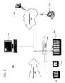
- FIG. 1is an illustrative diagram of an IPTV system in accordance with an illustrative embodiment.
- FIG. 1illustrates one embodiment of an IPTV environment 100 .
- the IPTV environment 100may include a network connection 102 , a set-top box 104 , a DVR 106 and a television 108 . Expanded illustrations of the IPTV environment 100 are further illustrated in FIGS. 2 and 3 .
- the set-top box 104is further described by FIG. 4 .
- the network connection 102provides a content stream including video, data, media, and other interactive content to the television 108 .
- the network connection 102may be a DSL connection.
- the data or media connection to the set-top box 104may be provided by any connection suitable for transmitting data, video, broadband, or other media content.
- the network connection 102 as a DSL connectionmay be particularly relevant because of the large number of homes already wired with a twisted copper pair, typically used for plain old telephone service.
- the network connection 102may have limited bandwidth in order to operate and supply digital content to the devices of the IPTV environment 100 .
- the content stream through the network connection 102may be a unicast broadcast intended only for the set-top box 104 and the corresponding user or it may be a multicast broadcast being simultaneously received and processed by a number of set-top boxes.
- the content streammay be a high-definition or regular digital broadcast sent and received from any number of networks, servers, advanced intelligent devices, or other networks or components.
- the content stream available through the network connection 102may be established with IPTV network components by sending an add stream or stream origination request.
- the add stream requestmay be a message or command sent from the set-top box 104 that requests a content stream for a specified channel, video-on-demand, program or other media content.
- the add stream requestmay be authenticated based on information, passwords, or other identifiers sent by the set-top box 104 .
- the DVR 106is integrated with the set-top box 104 .
- the set-top box 104allows a user to receive digital television service through the network connection 102 using Internet Protocol over a network infrastructure.
- the set-top box 104may be a device that functions as a translator or intermediary between the television 108 and the network connection 102 .
- the set-top box 104may convert, format, or translate the signal received through the network connection 102 to be displayed on the screen of the television 108 .
- the set-top box 104may be a computer or computing device providing communications on an IP network and decoding the video streaming media for display by the television 108 .
- the DVR 106may be a device that records video in a digital format to a disk drive or other memory medium.
- the set-top box 104 and DVR 106may include a processor, memory, and other common computing elements.
- the set-top box 104allows a user to specify and change the content stream streamed through the network connection 102 to the television 108 .
- the set-top box 104 and DVR 106may store and/or execute programs, operating systems, or instructions for controlling the media content, playback, user interaction, and other interactive features available to a user through the television 108 .
- the DVR 106may enable a user to capture video, media, or other content for playback from a disk or a memory of the DVR 106 .
- the DVR 106may provide the user with the ability to record programs, features, or other media for play back at the user's convenience. In most cases, the DVR 106 may store the digital stream from the network connection 102 directly to disk or playback at a specified time.
- the usermay set preferences in the set-top box 104 or DVR 106 for automatically or manually selecting and recording programs. For example, the user may specify that the DVR 106 is to record every program of a specified type that is available through the channels or contents stream of the network connection 102 . In another example, the user may set the DVR 106 to record a one-time event or a single program. For example, the user may use an infrared remote or cellular telephone to change channels and record programs. The user may interact with the set-top box 104 , DVR 106 , and television 108 using one or more remote control devices.
- the set-top box 104may include any number of buttons, indicators, displays, touch screens, or other interactive elements for receiving user input and providing information to the user.
- the set-top box 104 and DVR 106may communicate with or be connected to the television 108 through a hard-wired or wireless connection.
- the set-top box 104 and television 108may communicate through a high-definition multi media interface (HDMI).
- HDMIhigh-definition multi media interface
- the connectionmay be any digital audio/video interface suitable for transmitting and/or compressing media streams.
- the set-top box 104 and television 108may use any number of digital connection or analog standards and converters to send and receive information.
- the set-top box 104 and television 108may communicate through a wireless connection, such as Bluetooth® or WiFi, such as IEEE 802.11(n).
- the connection between the set-top box 104 and the television 108may be used to carry video, audio, and other device controlling signals.
- Other wireless standards and protocolsmay be similarly used to allow the set-top box 104 and television 108 to communicate in different rooms or locations.
- the set-top box 104may be able to determine that the television 108 is turned on, activated, or set to display content. For example, the power control of the television 108 may be plugged into the set-top box 104 .
- the set-top box 104may use a current detector or other suitable device to determine whether the television 108 is activated or otherwise enabled to display visual content.
- the television 108may send a heartbeat signal indicating status to the set-top box.
- the television 108may also proactively send a signal or message to the set-top box 104 when activated or deactivated.
- the set-top box 104may be able to determine whether the television 108 is being actively used or is still enabled.
- a power determination chipset within the set-top box 104may monitor the status of the television 108 to determine whether the television is active or powered up.
- the content provided through the network connection 102may establish whether the television 108 is active.
- the usermay use any number of remote control devices to control the set-top box 104 and DVR 106 , as well as the television 108 .
- the set-top box 104may transmit a drop or terminate signal to an IPTV content server through the network connection 102 .
- the signal sent from IPTV network resources through the network connection 102 from that point onmay indicate that the television 108 is inactive.
- a chipset residing in the television 108may send a signal to the set-top box 104 indicating that the power has been turned off.
- the signalmay be received through a wire line or a wireless connection between the set-top box 104 and the television 108 .
- the set-top box 104may use any number of methods for determining whether the television 108 is active. Once the set-top box 104 determines the television 108 has been turned off or powered down, the set-top box 104 reads the DVR 106 to determine whether a television show or other program is set to record or is currently recording. If a show currently recording, the network connection 102 remains active and the bandwidth remains available in order to allow the video content to be clearly recorded by the DVR 106 .
- the set-top box 104would go into a passive or standby mode and the DVR 106 may be turned off.
- the set-top box 104may only be activated if the DVR 106 is set to record a program or as activated by a user.
- a time stampmay be used by power control logic of the set-top box 104 to send an add stream request for the desired content and reactivate the DVR 106 for recording the specified program.
- the set-top box 104may cancel, terminate, or disconnect the content stream provided through the network connection 102 so that the bandwidth available through the network connection 102 may be available to other users or devices that also connect to the network connection 102 .
- the content stream available through the network connection 102may be ended by sending a drop stream signal, message, command, or request to the IPTV network or component delivering the content stream.
- the drop stream requestmay terminate the content stream delivered to the set-top box 104 so that the bandwidth that was being used to send data such as a television program or video on demand may be used by different elements within the IPTV environment 100 to provide improved bandwidth and/or throughput for the high-speed Internet connection that may be part of the network connection 102 .
- performancemay be enhanced by reallocating bandwidth that may be scarce as part of the network connection 102 .
- the set-top box 104Before the set-top box 104 is powered down, the set-top box 104 takes note of the next program or show that is to be recorded by the DVR 106 . As a result, the set-top box 104 may reactivate itself and the DVR 106 from standby in order to record the program using the DVR 106 and insuring that the full bandwidth and content available through the network connection 102 has been restored for active recording. Alternatively, the set-top box 104 may take a snapshot or request a list of all schedule DVR activity at the time the set-top box 104 goes into passive mode for activating and deactivating the set-top box 104 and DVR 106 .
- FIG. 2is an illustrative diagram of a home network in accordance with an illustrative embodiment.
- FIG. 2illustrates one embodiment of a home network 200 .
- the home network 200may include a number of elements, including a data connection 202 , a set-top box 204 , a DVR 206 , televisions 208 , 210 and 212 , a personal computer 214 , a wireless network 216 , a laptop 218 , and a cellular telephone 220 .
- the data connection 202 , the set-top box 204 , the DVR 206 , and the television 208are a particular implementation of the IPTV environment 100 of FIG. 1 .
- the data connection 202may provide video content, packets, information, and data to the set-top box 204 for distribution to the televisions 208 , 210 and 212 , as well as the personal computer 214 and the wireless network 216 .
- the set-top box 204may be configured to send add stream requests for each of the televisions 208 , 210 , and 212 .
- the set-top box 204may request a high-definition MPEG 4 content stream for the television that uses 8 MB.
- the set-top boxmay simultaneously process a change channel request that ends one stream and requests another stream for television 210 while television 212 has requested that a separate channel be recorded by the DVR 206 .
- the content streams for the television 210 and 212may occupy another 3 MB each.
- the bandwidthmay be reallocated for providing better performance to the personal computer 214 , the wireless network 216 , or the other televisions.
- the wireless network 216may further enable communication with the cellular telephone 220 and the laptop 218 .
- the wireless network 216may include a wireless router or server for sending and receiving data signals to the cellular telephone 220 , the laptop, and other household or user devices.
- the set-top box 204may be enabled to display content to each of the televisions 208 , 210 and 212 .
- the set-top box 204determines the next scheduled recording time for the DVR 206 .
- the scheduled recording timemay have been set by any number of users with access to the televisions 208 , 210 and 212 or the set-top box 204 .
- the programming for the set-top boxmay be done through the personal computer 214 or laptop 218 which may communicate directly with the set-top box 204 or communicate through a web or Internet portal available to each of the devices.
- the set-top box 204determines whether the DVR 206 is recording and the next time for which the DVR 206 is set to record a program. If the DVR 206 is recording for any of the televisions 208 , 210 and 212 , the data connection 202 remains active or the content stream to the set-top box 204 remains open so that the DVR 206 may continue to record. If, however, the DVR 206 is not set to record for some time, the set-top box 204 powers itself down and cancels the content stream available through the data connection 202 .
- the set-top box 204may enter a passive mode so that only a minimum amount of power is used to keep track of time and compare the current time against the next scheduled recording. Once the set-top box 204 determines a program needs to be recorded by the DVR 206 , the set-top box 204 awakes itself to full functionality and sends an add stream request for the specified content to be recorded by the DVR 206 . As a result, the data connection 202 may be used by the personal computer 214 and devices connected to the wireless network 216 in order to insure that these devices have proper availability to bandwidth and are not limited by bandwidth constraints, even when the televisions 208 , 210 and 212 have been turned off.
- the 8 Mb of bandwidth tied to different content streams delivered by the set-top box 204 to the televisions 208 , 210 , and 212may be diverted to the personal computer 214 , a wireless network 216 for enhanced communication, Internet browsing, and overall performance.
- the set-top box 204may cancel a content stream or portions of the content stream dedicated for providing programming for each of the televisions 208 , 210 and 212 .
- the content streammay be terminated if the DVR is not set to record a specified program.
- a drop stream requestis sent by the set-top box 204 to the IPTV content provider, more bandwidth may be potentially freed up for different uses or applications or be made available on the service provider network.
- the set-top box 204reactivates itself and reestablishes the content stream through the data connection 202 so that the DVR 206 may properly record the specified program.
- the set-top box 204may include a time display device that tracks the specified recording times for the DVR and reactivates the set-top box 204 to send add stream requests as programmed by the user.
- the data connection 202may have limited bandwidth and by disabling the connection or content stream received by the set-top box 204 when the televisions 208 , 210 and 212 are powered down, the data connection 202 may be used by the other devices in the home network 200 preserving bandwidth and increasing customer satisfaction.
- FIG. 3is an illustrative diagram of a home network in accordance with an illustrative embodiment.
- the home network 300 of FIG. 3includes many of the elements of FIG. 2 .
- the home network 300further includes the set-top box 302 and corresponding DVR 304 which are connected to the television 210 .
- the set-top box 204 and DVR 206are connected only to the television 208 .
- the illustrative embodimentsmay be particularly important for the home network 300 in which multiple set-top boxes 302 and 204 are being used because of the large bandwidth requirements of IPTV.
- the set-top box 302 and set-top box 204may function as previously described with minor exceptions. If the set-top box 204 determines that the television 208 has been turned off and that the content stream used by the set-top box 204 may be deactivated, the set-top box 204 deactivates the content stream through the data connection 202 . However, the set-top box 204 does not send a drop stream request for the stream provide through the data connection 202 to the set-top box 302 and corresponding television 210 .
- only the set-top box 302may determine when the content provided through the data connection 202 may be turned off or disabled for the television 210 in order to preserve bandwidth through the data connection.
- the set-top box 302 and the set-top box 204both use their corresponding DVRs 302 and 206 to determine whether the content stream for each should be deactivated once the television 210 and 208 has been powered down by the user.
- FIG. 4is a block diagram of a set-top box in accordance with an illustrative embodiment.
- FIG. 4illustrates one embodiment of a set-top box 400 and is shown for illustration purposes only, and not as a limitation of required elements.
- the set-top box 400may include numerous elements including a processor 402 , a transceiver 404 , a power control 406 , a memory 408 , an interface application 410 , and DVR hardware and software 412 .
- the set-top box 400may be a combination of hardware and software elements.
- the set-top box 400may incorporate various structures, formats, and hardware/software combinations included in available set-top boxes.
- the processor 402may be a computer processor, or other processing device or element used by the set-top box to process instructions, convert and translate data, render video, and otherwise perform data manipulation and processing, as required by the set-top box 400 .
- the memory 408may include a hard drive and flash memory for storing television programs, data, applications, and user preferences. However, the memory 408 may be any static or dynamic memory type or configuration suitable for storing and accessing electronic information and data. In one embodiment, the memory 408 includes a 500 GB hard drive for storing video images, an operating system, and applications as specified by the user, and a 4 GB SDRAM for processing data and applications.
- the transceiver 404may be configured to communicate with an IPTV service provider or other content provider.
- the content service providermay provide programming or content that is used by the set-top box 400 to be displayed by a television.
- the transceiver 404may configure, format, or translate the content stream for display by a television.
- the transceiver 404may also send information to the content service provider that may specify a selected channel or user input or changes thereto.
- the transceiver 404may send a signal informing the content service provider that the set-top box 400 is going to be powered down and therefore the content stream provided to the set-top box may be temporarily deactivated, cut-off, or cancelled in order to preserve bandwidth available through the data connection or IPTV connection.
- the transceiver 404may send add and drop stream requests to provide the channels or media content requested by the DVR or one or more connected televisions.
- the interface application 410is digital logic. In another embodiment, the interface application 410 may be stored in the memory 408 for coordinating communication. The interface application 410 may communicate with the DVR hardware and software 412 to determine whether a program is currently being recorded or the next time the DVR hardware and software 412 needs to record a television program. In one example, the interface application 410 may note a time stamp at which the set-top box 400 needs to be active so that the DVR hardware and software 412 may be activated to record a user-selected program. The interface application 410 may also take a snapshot of all scheduled recording information, including time, date, duration, and channel, for each recording scheduled that may be saved in a matrix form, chart, or other simplified format.
- the interface application 410may also communicate with the television to determine power status or mode. For example, if the television is hibernating, the interface application 410 may send a signal to the power control 400 to turn off the DVR hardware and software 412 and set the set-top box to enter a sleep or standby mode. The interface application 410 may also send and receive messages or data to the content service provider. For example, the interface application 410 may send a message to a content server indicating that the content stream may be terminated because it is no longer being used by the set-top box or DVR hardware and software 412 .
- the power control 406may be used to power down the set-top box 400 and the DVR hardware and software 412 .
- the power control 406may place the set-top box 400 in a passive mode until it is activated by the user or until a time specified for recording a program is met as received from the interface application 410 or, alternatively, by the DVR hardware and software 412 .
- the power control 406may completely turn off the DVR hardware and software 412 and most of the set-top box in order to preserve power.
- the power control 406may be a chip set that includes a clock and logic for comparing the current time against the next schedule recording time for the DVR hardware and software 412 .
- the power control 406may power down all other elements of the set-top box 400 until the next scheduled recording time.
- the set-top box 400may record one or more content streams at a time for multiple televisions sets or for requested programming that runs concurrently.
- the power control 406may allow the set-top box 400 to be activated or deactivated when the interconnected television or televisions are not in use, and the DVR hardware and software 412 does not need access to the content stream to record a program. As a result, the power control 406 conserves electricity, as well as enabling the set-top box 400 to conserve bandwidth used by the set-top box 400 to provide video content to the DVR hardware and software 412 and/or to one or more interconnected televisions.
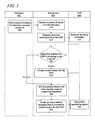
- FIG. 5is a flowchart of a process for dynamic bandwidth allocation in accordance with an illustrative embodiment.
- the process of FIG. 5may be implemented by a television 502 , set-top box 504 , and a DVR 506 .
- the DVR 506may be integrated with the set-top box 504 or may be an externally linked DVR.
- the television 502 , set-top box 504 , and DVR 506may be linked or communicate through hard-wired or wireless connections.
- the television 502may represent one or more televisions in communication with the set-top box.
- an add stream requestmay have been sent to an IPTV service provider to provide programming for one or more televisions.
- the processmay be with in the television 502 sending a signal indicating the television has been turned off (step 508 ).
- the power down or inactivity signal of step 508may be sent as the television 502 goes from an active or powered mode to an inactive mode.
- the signalmay be sent actively, such as through an affirmative message, or passively, such as through a current detector of the television.
- the set-top box 504receives the power-off signal from the television (step 510 ).
- the set-top box 504requests recording information from the DVR (step 512 ).
- the recording informationmay specify the recording schedule for the DVR 506 as of the time the power-off signal is received.
- the recording schedulemay list the time, date, channel, and duration for which the programs are to be recorded.
- the set-top box 504may particularly request the schedule recording information for the next week.
- the DVR 506sends the recording information (step 514 ).
- the recording informationmay be sent in a format that may be easily stored and read by the DVR 506 and/or the set-top box 504 .
- the set-top box 504determines whether the DVR recording or set to record (step 516 ). If the set-top box 504 determines the DVR is recording, the set-top box 504 provides the content stream for the DVR (step 518 ). The content stream continues to be streamed in step 522 so that the DVR 506 may record the specified program without interruption. Next, the set-top box 504 determines whether the DVR is recording or set to record (step 516 ).
- the set-top box 504determines the DVR is set to record in step 516 , the set-top box 504 ends the content stream and enters standby mode for preserving bandwidth (step 520 ).
- the set-top box 504may send a signal, message, or other communication to a server, switch, router, or other network device of the content service provider in order to end the content stream.
- the set-top boxmay send a drop stream request for one or more televisions.
- the bandwidth of a data connection into a home, business, or organizationmay be freed up for other computing devices, applications, or usage.
- the set-top box 504powers up at a pre-defined recording time to provide the content stream for the DVR (step 522 ).
- power logic or a power chipset of the set-top box 504may power up all other components of the set-top box 504 and send an add stream request to reestablish the content stream through a data connection with the IPTV content service provider.
- the DVR 506records the specified program (step 524 ).
- the set-top box 504may determine whether the DVR is recording or set to record (step 516 ). In one embodiment, when returning to step 516 , the set-top box 504 may update or request an update of recording information from the DVR 506 .
- FIG. 6is a flowchart of a process for managing bandwidth using a set-top box in accordance with an illustrative embodiment.
- the process of FIG. 6may be implemented by a set-top box.
- the set-top boxmay include a DVR or DVR functionality.
- the processmay begin by providing a content stream to a television (step 602 ).
- the content streammay be used to provide television programming, video, and other media to one or more televisions as requested through an add stream request, message, or command.
- the DVR of the set-top boxmay also use the content stream to record and store specified programs.
- the set-top boxdetects the television has been powered down (step 604 ).
- the set-top boxmay detect the change in television status through a current detector, affirmative shut-down signal from the television received through a wired or wireless connection, heart-beat signal, or other detection means.
- the set-top boxrequests recording information from the DVR (step 606 ).
- the DVRmay be integrated with the set-top box or may be externally connected.
- the recording informationmay specify the next scheduled recording time if set or specified.
- the recording informationmay further include all scheduled recording times or a number of the schedule recording times for a time period, such as a day, week, or month.
- the set-top boxmay note the recording time by using a time stamp. For example, the set-top box may note that the next scheduled time is Jun. 21, 2012 at 6:55 p.m. on channel 32 or use a time stamp, such as “d06212012t1855c032”.
- the set-top boxdetermines whether the DVR is active (step 608 ). During step 608 , the set-top box may determine whether the DVR is recording at the moment or whether it will be recording within a specified period, such as fifteen minutes. If the DVR is active, the set-top box requests recording information from the DVR. The recording information may further specify how long the DVR will be recording a specified program or interactive content.
- the set-top boxsends a drop stream request to the IPTV content provider and enters a standby mode (step 610 ).
- the drop stream requestmay be sent to a server, node, head end content provider equipment, or other IPTV network device or application for terminating the content stream.
- the set-top boxpreserves dedicated bandwidth through the network connection for other devices of the home, business, or organization, or other customers of the content service provider.
- the set-top boxmay also preserve energy by going into the passive mode while the television is not activated and the DVR is not active.
- the set-top boxawakes the set-top box from standby mode at a next scheduled recording time or based on a customer activation and sends an add stream request to the IPTV content provider based on the recording information (step 612 ).
- the set-top boxmay reactivate itself any number of times based on a time stamp or on the recording information as determined in step 606 .
- FIGS. 5 and 6may be implemented for any number of televisions connected to the set-top box. Alternatively, the process may be simultaneously implemented by multiple set-top boxes that share access to a network connection carrying multiple content streams for televisions, computing devices, and other network communicating devices.
Landscapes
- Engineering & Computer Science (AREA)
- Signal Processing (AREA)
- Multimedia (AREA)
- Computer Networks & Wireless Communication (AREA)
- Databases & Information Systems (AREA)
- Health & Medical Sciences (AREA)
- Social Psychology (AREA)
- General Health & Medical Sciences (AREA)
- Computer Graphics (AREA)
- General Engineering & Computer Science (AREA)
- Software Systems (AREA)
- Quality & Reliability (AREA)
- Computer Security & Cryptography (AREA)
- Two-Way Televisions, Distribution Of Moving Picture Or The Like (AREA)
Abstract
Description
Claims (21)
Priority Applications (1)
| Application Number | Priority Date | Filing Date | Title |
|---|---|---|---|
| US13/847,382US9015777B2 (en) | 2007-08-31 | 2013-03-19 | System and method for dynamic bandwidth allocation |
Applications Claiming Priority (2)
| Application Number | Priority Date | Filing Date | Title |
|---|---|---|---|
| US11/897,835US8418194B2 (en) | 2007-08-31 | 2007-08-31 | System and method for dynamic bandwidth allocation |
| US13/847,382US9015777B2 (en) | 2007-08-31 | 2013-03-19 | System and method for dynamic bandwidth allocation |
Related Parent Applications (1)
| Application Number | Title | Priority Date | Filing Date |
|---|---|---|---|
| US11/897,835ContinuationUS8418194B2 (en) | 2007-08-31 | 2007-08-31 | System and method for dynamic bandwidth allocation |
Publications (2)
| Publication Number | Publication Date |
|---|---|
| US20130227626A1 US20130227626A1 (en) | 2013-08-29 |
| US9015777B2true US9015777B2 (en) | 2015-04-21 |
Family
ID=40409640
Family Applications (2)
| Application Number | Title | Priority Date | Filing Date |
|---|---|---|---|
| US11/897,835Active2029-01-26US8418194B2 (en) | 2007-08-31 | 2007-08-31 | System and method for dynamic bandwidth allocation |
| US13/847,382ActiveUS9015777B2 (en) | 2007-08-31 | 2013-03-19 | System and method for dynamic bandwidth allocation |
Family Applications Before (1)
| Application Number | Title | Priority Date | Filing Date |
|---|---|---|---|
| US11/897,835Active2029-01-26US8418194B2 (en) | 2007-08-31 | 2007-08-31 | System and method for dynamic bandwidth allocation |
Country Status (1)
| Country | Link |
|---|---|
| US (2) | US8418194B2 (en) |
Families Citing this family (75)
| Publication number | Priority date | Publication date | Assignee | Title |
|---|---|---|---|---|
| US10693415B2 (en) | 2007-12-05 | 2020-06-23 | Solaredge Technologies Ltd. | Testing of a photovoltaic panel |
| US11881814B2 (en) | 2005-12-05 | 2024-01-23 | Solaredge Technologies Ltd. | Testing of a photovoltaic panel |
| US9112379B2 (en) | 2006-12-06 | 2015-08-18 | Solaredge Technologies Ltd. | Pairing of components in a direct current distributed power generation system |
| US11687112B2 (en) | 2006-12-06 | 2023-06-27 | Solaredge Technologies Ltd. | Distributed power harvesting systems using DC power sources |
| US8319483B2 (en) | 2007-08-06 | 2012-11-27 | Solaredge Technologies Ltd. | Digital average input current control in power converter |
| US11296650B2 (en)* | 2006-12-06 | 2022-04-05 | Solaredge Technologies Ltd. | System and method for protection during inverter shutdown in distributed power installations |
| US8473250B2 (en) | 2006-12-06 | 2013-06-25 | Solaredge, Ltd. | Monitoring of distributed power harvesting systems using DC power sources |
| US11888387B2 (en)* | 2006-12-06 | 2024-01-30 | Solaredge Technologies Ltd. | Safety mechanisms, wake up and shutdown methods in distributed power installations |
| US11735910B2 (en) | 2006-12-06 | 2023-08-22 | Solaredge Technologies Ltd. | Distributed power system using direct current power sources |
| US9130401B2 (en) | 2006-12-06 | 2015-09-08 | Solaredge Technologies Ltd. | Distributed power harvesting systems using DC power sources |
| US12316274B2 (en) | 2006-12-06 | 2025-05-27 | Solaredge Technologies Ltd. | Pairing of components in a direct current distributed power generation system |
| US8384243B2 (en) | 2007-12-04 | 2013-02-26 | Solaredge Technologies Ltd. | Distributed power harvesting systems using DC power sources |
| US8947194B2 (en) | 2009-05-26 | 2015-02-03 | Solaredge Technologies Ltd. | Theft detection and prevention in a power generation system |
| US8618692B2 (en) | 2007-12-04 | 2013-12-31 | Solaredge Technologies Ltd. | Distributed power system using direct current power sources |
| US11309832B2 (en) | 2006-12-06 | 2022-04-19 | Solaredge Technologies Ltd. | Distributed power harvesting systems using DC power sources |
| US11569659B2 (en) | 2006-12-06 | 2023-01-31 | Solaredge Technologies Ltd. | Distributed power harvesting systems using DC power sources |
| US8816535B2 (en) | 2007-10-10 | 2014-08-26 | Solaredge Technologies, Ltd. | System and method for protection during inverter shutdown in distributed power installations |
| US8963369B2 (en) | 2007-12-04 | 2015-02-24 | Solaredge Technologies Ltd. | Distributed power harvesting systems using DC power sources |
| US9088178B2 (en) | 2006-12-06 | 2015-07-21 | Solaredge Technologies Ltd | Distributed power harvesting systems using DC power sources |
| US8319471B2 (en) | 2006-12-06 | 2012-11-27 | Solaredge, Ltd. | Battery power delivery module |
| US11855231B2 (en) | 2006-12-06 | 2023-12-26 | Solaredge Technologies Ltd. | Distributed power harvesting systems using DC power sources |
| US8013472B2 (en) | 2006-12-06 | 2011-09-06 | Solaredge, Ltd. | Method for distributed power harvesting using DC power sources |
| US8418194B2 (en) | 2007-08-31 | 2013-04-09 | Centurylink Intellectual Property Llc | System and method for dynamic bandwidth allocation |
| US20090089184A1 (en)* | 2007-09-28 | 2009-04-02 | Embarq Holdings Company, Llc | Content portal for media distribution |
| US9414019B2 (en)* | 2007-10-05 | 2016-08-09 | At&T Intellectual Property I, Lp | Television channel display device and method thereof |
| US8355486B2 (en) | 2007-10-31 | 2013-01-15 | Centurylink Intellectual Property Llc | System and method for inbound call billing |
| KR101315414B1 (en)* | 2007-11-29 | 2013-10-07 | 삼성전자주식회사 | Image processing apparatus and control method of the same |
| CN105244905B (en) | 2007-12-05 | 2019-05-21 | 太阳能安吉有限公司 | Release mechanism in distributed power device is waken up and method for closing |
| US11264947B2 (en) | 2007-12-05 | 2022-03-01 | Solaredge Technologies Ltd. | Testing of a photovoltaic panel |
| WO2009072076A2 (en) | 2007-12-05 | 2009-06-11 | Solaredge Technologies Ltd. | Current sensing on a mosfet |
| US20090147779A1 (en)* | 2007-12-07 | 2009-06-11 | Telefonaktiebolaget Lm Ericsson (Publ) | Methods, iptv (internet protocol television) terminal, and iptv control server for iptv bandwidth management |
| US8001236B2 (en)* | 2008-03-13 | 2011-08-16 | Sharp Laboratories Of America, Inc. | Methods and systems for content-consumption device monitoring and control |
| US8111052B2 (en) | 2008-03-24 | 2012-02-07 | Solaredge Technologies Ltd. | Zero voltage switching |
| EP2294669B8 (en) | 2008-05-05 | 2016-12-07 | Solaredge Technologies Ltd. | Direct current power combiner |
| US7782884B2 (en) | 2008-07-07 | 2010-08-24 | Embarq Holdings Company, Llc | System and method for adjusting bandwidth based on a time of day profile |
| US10021437B1 (en)* | 2008-09-15 | 2018-07-10 | The Directv Group, Inc. | Method and system for discontinuing a channel stream in a multi-terminal system |
| US8793717B2 (en)* | 2008-10-31 | 2014-07-29 | The Nielsen Company (Us), Llc | Probabilistic methods and apparatus to determine the state of a media device |
| US8302145B2 (en) | 2008-11-20 | 2012-10-30 | At&T Intellectual Property I, Lp | System and method to manage a content stream |
| US8434121B2 (en)* | 2009-10-16 | 2013-04-30 | At&T Intellectual Property I, L.P. | System and method for monitoring whole home digital video recorder usage for internet protocol television |
| US12418177B2 (en) | 2009-10-24 | 2025-09-16 | Solaredge Technologies Ltd. | Distributed power system using direct current power sources |
| CN102668549B (en)* | 2009-11-16 | 2015-06-03 | 瑞典爱立信有限公司 | Method and apparatus for standby handling in a streaming media receiver |
| US8266314B2 (en)* | 2009-12-16 | 2012-09-11 | International Business Machines Corporation | Automated audio or video subset network load reduction |
| CN102147968B (en)* | 2010-02-06 | 2012-10-10 | 鸿富锦精密工业(深圳)有限公司 | Power line communication equipment |
| US10230310B2 (en) | 2016-04-05 | 2019-03-12 | Solaredge Technologies Ltd | Safety switch for photovoltaic systems |
| GB2485527B (en) | 2010-11-09 | 2012-12-19 | Solaredge Technologies Ltd | Arc detection and prevention in a power generation system |
| US10673229B2 (en) | 2010-11-09 | 2020-06-02 | Solaredge Technologies Ltd. | Arc detection and prevention in a power generation system |
| US10673222B2 (en) | 2010-11-09 | 2020-06-02 | Solaredge Technologies Ltd. | Arc detection and prevention in a power generation system |
| US9847844B2 (en)* | 2010-11-29 | 2017-12-19 | Time Warner Cable Enterprises Llc | Technique for usage forecasting in a switched digital video system |
| US8643693B2 (en)* | 2010-12-30 | 2014-02-04 | Verizon Patent And Licensing Inc. | System and method for providing television video conferencing using a computing device |
| GB2483317B (en) | 2011-01-12 | 2012-08-22 | Solaredge Technologies Ltd | Serially connected inverters |
| CN102752648A (en)* | 2011-04-18 | 2012-10-24 | 鸿富锦精密工业(深圳)有限公司 | Set top box and power-saving method thereof |
| US9167295B2 (en)* | 2011-06-07 | 2015-10-20 | Comcast Cable Communications, Llc | Multi-source content retrieval |
| US8570005B2 (en) | 2011-09-12 | 2013-10-29 | Solaredge Technologies Ltd. | Direct current link circuit |
| EP2579504B1 (en)* | 2011-10-05 | 2018-12-05 | Swisscom AG | Method and system for remote control of an electric consumer |
| US9167313B1 (en) | 2011-10-27 | 2015-10-20 | Amazon Technologies, Inc. | Methods and system for transferring data for remote storage |
| GB2498365A (en) | 2012-01-11 | 2013-07-17 | Solaredge Technologies Ltd | Photovoltaic module |
| GB2498790A (en) | 2012-01-30 | 2013-07-31 | Solaredge Technologies Ltd | Maximising power in a photovoltaic distributed power system |
| GB2498791A (en) | 2012-01-30 | 2013-07-31 | Solaredge Technologies Ltd | Photovoltaic panel circuitry |
| US9853565B2 (en) | 2012-01-30 | 2017-12-26 | Solaredge Technologies Ltd. | Maximized power in a photovoltaic distributed power system |
| GB2499991A (en) | 2012-03-05 | 2013-09-11 | Solaredge Technologies Ltd | DC link circuit for photovoltaic array |
| US10115841B2 (en) | 2012-06-04 | 2018-10-30 | Solaredge Technologies Ltd. | Integrated photovoltaic panel circuitry |
| KR20140085696A (en)* | 2012-12-27 | 2014-07-08 | (주)휴맥스 | Media system and method of controlling the same |
| US9548619B2 (en) | 2013-03-14 | 2017-01-17 | Solaredge Technologies Ltd. | Method and apparatus for storing and depleting energy |
| EP3506370B1 (en) | 2013-03-15 | 2023-12-20 | Solaredge Technologies Ltd. | Bypass mechanism |
| CN104469463B (en)* | 2014-12-26 | 2017-05-17 | 山东泰信电子股份有限公司 | Automatic standby method for set top box and television |
| US9924224B2 (en) | 2015-04-03 | 2018-03-20 | The Nielsen Company (Us), Llc | Methods and apparatus to determine a state of a media presentation device |
| US10009914B2 (en) | 2015-07-24 | 2018-06-26 | Google Llc | Bandwidth throttling based on home occupancy |
| US11177663B2 (en) | 2016-04-05 | 2021-11-16 | Solaredge Technologies Ltd. | Chain of power devices |
| US11018623B2 (en) | 2016-04-05 | 2021-05-25 | Solaredge Technologies Ltd. | Safety switch for photovoltaic systems |
| US12057807B2 (en) | 2016-04-05 | 2024-08-06 | Solaredge Technologies Ltd. | Chain of power devices |
| US10798374B2 (en)* | 2016-10-28 | 2020-10-06 | Enseo, Inc. | Set-top box with self-monitoring and system and method for use of same |
| US11831934B2 (en) | 2022-01-11 | 2023-11-28 | Enseo, Llc | Set-top box with self-monitoring and system and method for use of same |
| US12212792B2 (en) | 2016-10-28 | 2025-01-28 | Enseo, Llc | Set-top box with self-monitoring and system and method for use of same |
| CN107040742B (en)* | 2017-03-10 | 2019-10-18 | 浙江宇视科技有限公司 | An anomaly detection method, network hard disk video recorder NVR and video server |
| CN110798643B (en)* | 2019-11-25 | 2022-02-22 | 广州市奥威亚电子科技有限公司 | User terminal equipment and video and audio quality assurance system using same |
Citations (76)
| Publication number | Priority date | Publication date | Assignee | Title |
|---|---|---|---|---|
| US5712969A (en) | 1993-09-24 | 1998-01-27 | Robert Bosch Gmbh | Method for completely reprogramming an erasable, non-volatile memory |
| US5768539A (en) | 1994-05-27 | 1998-06-16 | Bell Atlantic Network Services, Inc. | Downloading applications software through a broadcast channel |
| US5801753A (en) | 1995-08-11 | 1998-09-01 | General Instrument Corporation Of Delaware | Method and apparatus for providing an interactive guide to events available on an information network |
| US5894320A (en) | 1996-05-29 | 1999-04-13 | General Instrument Corporation | Multi-channel television system with viewer-selectable video and audio |
| US5920701A (en) | 1995-01-19 | 1999-07-06 | Starburst Communications Corporation | Scheduling data transmission |
| US5931908A (en) | 1996-12-23 | 1999-08-03 | The Walt Disney Corporation | Visual object present within live programming as an actionable event for user selection of alternate programming wherein the actionable event is selected by human operator at a head end for distributed data and programming |
| US5940072A (en) | 1996-08-15 | 1999-08-17 | Samsung Information Systems America | Graphics decompression using system ROM indexing in TV set top box |
| US5960445A (en) | 1996-04-24 | 1999-09-28 | Sony Corporation | Information processor, method of updating a program and information processing system |
| US6032134A (en) | 1998-11-18 | 2000-02-29 | Weissman; Steven I. | Credit card billing system for identifying expenditures on a credit card account |
| US6040851A (en) | 1998-01-20 | 2000-03-21 | Conexant Systems, Inc. | Small-format subsystem for broadband communication services |
| US6046760A (en) | 1996-05-06 | 2000-04-04 | Samsung Electronics Co., Ltd. | Set top board for video on demand service and a computer system mounting the same |
| US6075863A (en) | 1996-02-28 | 2000-06-13 | Encanto Networks | Intelligent communication device |
| US6088051A (en) | 1994-08-01 | 2000-07-11 | Sony Europa B.V. | System and method for user-server telecommunication in accordance with performance capabilities of a controller |
| US6088330A (en) | 1997-09-09 | 2000-07-11 | Bruck; Joshua | Reliable array of distributed computing nodes |
| US6138271A (en) | 1996-06-26 | 2000-10-24 | Rockwell Technologies, Llc | Operating system for embedded computers |
| US6175861B1 (en) | 1998-02-06 | 2001-01-16 | Henry R. Williams, Jr. | Apparatus and method for providing computer display data from a computer system to a remote display device |
| US6195797B1 (en) | 1998-02-06 | 2001-02-27 | Henry R. Williams, Jr. | Apparatus and method for providing computer display data from a computer system to a remote display device |
| US6202211B1 (en) | 1998-02-06 | 2001-03-13 | Henry R. Williams, Jr. | Method and apparatus for providing television signals to multiple viewing systems on a network |
| US6246434B1 (en) | 1996-10-14 | 2001-06-12 | Kabushiki Kaisha Toshiba | Video apparatus which can be adjusted easily |
| US6256785B1 (en) | 1996-12-23 | 2001-07-03 | Corporate Media Patners | Method and system for providing interactive look-and-feel in a digital broadcast via an X-Y protocol |
| US6259443B1 (en) | 1998-02-06 | 2001-07-10 | Henry R. Williams, Jr. | Method and apparatus for enabling multiple users to concurrently access a remote server using set-top boxes |
| US6321078B1 (en) | 1999-06-16 | 2001-11-20 | Ronald J. Menelli | System and method for providing expense reports to wireless service subscribers |
| US6331876B1 (en) | 1996-11-12 | 2001-12-18 | U.S. Philips Corporation | Method of updating software in a video receiver |
| US6347294B1 (en) | 1998-09-22 | 2002-02-12 | International Business Machines Corporation | Upgradeable highly integrated embedded CPU system |
| US20020021678A1 (en) | 2000-07-06 | 2002-02-21 | Antony Heatwole | Apportioning bandwidth capacity in communication switching systems |
| US20020069420A1 (en) | 2000-04-07 | 2002-06-06 | Chris Russell | System and process for delivery of content over a network |
| US6424947B1 (en) | 1997-09-29 | 2002-07-23 | Nds Limited | Distributed IRD system |
| US6469742B1 (en) | 1999-04-12 | 2002-10-22 | Koninklijke Philips Electronics N.V. | Consumer electronic devices with adaptable upgrade capability |
| US20030074662A1 (en) | 2001-08-29 | 2003-04-17 | Digeo, Inc. | System and method for capturing video frames for focused navigation within a user interface |
| US6614470B1 (en) | 1999-02-26 | 2003-09-02 | Sony Corporation | Devices and methods for processing digital image data compatible with a television receiver |
| US6618754B1 (en) | 1995-10-23 | 2003-09-09 | Sun Microsystems, Inc. | System for transmission of embedded applications over a network |
| US6637029B1 (en) | 1997-07-03 | 2003-10-21 | Nds Limited | Intelligent electronic program guide |
| US6654835B1 (en) | 2000-03-23 | 2003-11-25 | International Business Machines Corporation | High bandwidth data transfer employing a multi-mode, shared line buffer |
| US6681393B1 (en) | 1997-06-06 | 2004-01-20 | Nds Limited | Viewer interaction feedback method and system for use with an interactive telecommunication system |
| US6738983B1 (en) | 1995-05-26 | 2004-05-18 | Irdeto Access, Inc. | Video pedestal network |
| US20050015806A1 (en) | 2003-07-16 | 2005-01-20 | Patel Harish N. | Method and system for optimizing the bandwidth for an audio/video network |
| US20050073518A1 (en) | 2003-10-02 | 2005-04-07 | Raymond Bontempi | Method and system for detecting a power status of a display device |
| US6895595B2 (en) | 1998-05-29 | 2005-05-17 | Opentv, Inc. | Module manager for interactive television system |
| US20050175181A1 (en) | 2003-09-05 | 2005-08-11 | Bergs Magnus H. | Method and system for access to data and/or communication networks via wireless access points, as well as a corresponding computer program and a corresponding computer-readable storage medium |
| US6970641B1 (en) | 2000-09-15 | 2005-11-29 | Opentv, Inc. | Playback of interactive programs |
| US6975594B1 (en) | 2000-06-27 | 2005-12-13 | Lucent Technologies Inc. | System and method for providing controlled broadband access bandwidth |
| US20060031888A1 (en) | 2004-04-30 | 2006-02-09 | Sparrell Carlton J | Centralized resource management and un-managed device support |
| US7003783B2 (en) | 2001-01-18 | 2006-02-21 | Sony Service Centre (Europe) N.V. | Method and device for providing downloaded objects to an application |
| US20060064730A1 (en) | 2004-09-17 | 2006-03-23 | Jacob Rael | Configurable entertainment network |
| US7027768B2 (en) | 2001-10-12 | 2006-04-11 | Bellsouth Intellectual Property Corporation | Method and systems using a set-top box and communicating between a remote data network and a wireless communication network |
| US7042516B2 (en) | 2001-04-20 | 2006-05-09 | Sony Corporation | Video signal switching apparatus and control method thereof |
| US20060114360A1 (en) | 2004-12-01 | 2006-06-01 | Sbc Knowledge Ventures, L.P. | Device, system, and method for managing television tuners |
| US7069578B1 (en) | 2000-02-04 | 2006-06-27 | Scientific-Atlanta, Inc. | Settop cable television control device and method including bootloader software and code version table for maintaining and updating settop receiver operating system software |
| US7072950B2 (en) | 2001-01-23 | 2006-07-04 | Sony Corporation | Method and apparatus for operating system and application selection |
| US20060225106A1 (en) | 2005-03-31 | 2006-10-05 | Bedingfield James C Sr | Presence detection in a bandwidth management system |
| US7124194B2 (en) | 1994-10-12 | 2006-10-17 | Touchtunes Music Corporation | Audiovisual distribution system for playing an audiovisual piece among a plurality of audiovisual devices connected to a central server through a network |
| US20070044119A1 (en) | 2005-08-19 | 2007-02-22 | Sbc Knowledge Ventures, L.P. | System and method of managing video streams to a set top box |
| US20070061830A1 (en) | 2005-09-14 | 2007-03-15 | Sbc Knowledge Ventures L.P. | Audio-based tracking system for IPTV viewing and bandwidth management |
| US7200683B1 (en) | 1999-08-17 | 2007-04-03 | Samsung Electronics, Co., Ltd. | Device communication and control in a home network connected to an external network |
| US7222293B1 (en) | 1999-08-12 | 2007-05-22 | Applieoe, Inc. | Professional time tracking and reporting system |
| US7251255B1 (en)* | 2002-08-23 | 2007-07-31 | Digeo, Inc. | System and method for allocating resources across a plurality of distributed nodes |
| US20070214076A1 (en) | 2006-03-10 | 2007-09-13 | Experian-Scorex, Llc | Systems and methods for analyzing data |
| US20070220577A1 (en) | 2006-03-15 | 2007-09-20 | Kongalath George P | Method and media manager client unit for optimising network resources usage |
| US20070283397A1 (en) | 2006-05-31 | 2007-12-06 | Sbc Knowledge Ventures, L.P. | Passive video caching for edge aggregation devices |
| US20070291765A1 (en) | 2006-06-20 | 2007-12-20 | Harris Corporation | Systems and methods for dynamic mode-driven link management |
| US20080049787A1 (en) | 2006-08-22 | 2008-02-28 | Mcnaughton James L | System and method for controlling network bandwidth with a connection admission control engine |
| US7353212B1 (en) | 2000-05-23 | 2008-04-01 | Microsoft Corporation | Method and structure for assigning a transaction cost |
| US20080104202A1 (en) | 2006-10-25 | 2008-05-01 | Microsoft Corporation | Multi-DVR Media Content Arbitration |
| US7397763B2 (en) | 2001-12-28 | 2008-07-08 | Nortel Networking Llp | Admissions control in a connectionless communications network |
| US20080263621A1 (en) | 2007-04-17 | 2008-10-23 | Horizon Semiconductors Ltd. | Set top box with transcoding capabilities |
| US20080288991A1 (en) | 2007-05-15 | 2008-11-20 | Embarq Holdings Company, Llc | System and method for reducing network bandwidth for distributing video programming |
| US7492758B2 (en) | 2003-09-23 | 2009-02-17 | International Business Machines Corporation | Wireless telephone system including voice over IP and POTS |
| US20090064252A1 (en) | 2007-08-31 | 2009-03-05 | Embarq Holdings Company, Llc | System and method for dynamic bandwidth allocation |
| US20090141735A1 (en) | 2006-05-31 | 2009-06-04 | Johan Kolhi | Multicast Control |
| US7587124B2 (en) | 2004-01-20 | 2009-09-08 | Pioneer Corporation | Apparatus, method, and computer product for recognizing video contents, and for video recording |
| US7587512B2 (en) | 2002-10-16 | 2009-09-08 | Eric White | System and method for dynamic bandwidth provisioning |
| US20090234996A1 (en) | 2008-03-12 | 2009-09-17 | Embarq Holdings Company, Llc | System and method for dynamic bandwidth determinations |
| US20100002723A1 (en) | 2008-07-07 | 2010-01-07 | Embarq Holdings Company, Llc | System and method for adjusting bandwidth based on a time of day profile |
| US7698432B2 (en) | 1999-10-22 | 2010-04-13 | Nomadix, Inc. | Systems and methods for dynamic bandwidth management on a per subscriber basis in a communications network |
| US7725338B1 (en) | 2000-09-15 | 2010-05-25 | Palmsource Inc. | Time based profile management on palmtop computer |
| US8019683B1 (en) | 2007-11-02 | 2011-09-13 | At&T Mobility Ii Llc | Intelligent charging for services |
Family Cites Families (1)
| Publication number | Priority date | Publication date | Assignee | Title |
|---|---|---|---|---|
| US6086051A (en)* | 1998-01-29 | 2000-07-11 | Wiebe; John S. | Portable versatile structure |
- 2007
- 2007-08-31USUS11/897,835patent/US8418194B2/enactiveActive
- 2013
- 2013-03-19USUS13/847,382patent/US9015777B2/enactiveActive
Patent Citations (87)
| Publication number | Priority date | Publication date | Assignee | Title |
|---|---|---|---|---|
| US5712969A (en) | 1993-09-24 | 1998-01-27 | Robert Bosch Gmbh | Method for completely reprogramming an erasable, non-volatile memory |
| US5768539A (en) | 1994-05-27 | 1998-06-16 | Bell Atlantic Network Services, Inc. | Downloading applications software through a broadcast channel |
| US5978855A (en) | 1994-05-27 | 1999-11-02 | Bell Atlantic Network Services, Inc. | Downloading applications software through a broadcast channel |
| US6088051A (en) | 1994-08-01 | 2000-07-11 | Sony Europa B.V. | System and method for user-server telecommunication in accordance with performance capabilities of a controller |
| US6684403B1 (en) | 1994-08-01 | 2004-01-27 | Sony Europa B.V. | System and method for user-server telecommunication in accordance with performance capabilities of a controller |
| US7124194B2 (en) | 1994-10-12 | 2006-10-17 | Touchtunes Music Corporation | Audiovisual distribution system for playing an audiovisual piece among a plurality of audiovisual devices connected to a central server through a network |
| US5920701A (en) | 1995-01-19 | 1999-07-06 | Starburst Communications Corporation | Scheduling data transmission |
| US6738983B1 (en) | 1995-05-26 | 2004-05-18 | Irdeto Access, Inc. | Video pedestal network |
| US5801753A (en) | 1995-08-11 | 1998-09-01 | General Instrument Corporation Of Delaware | Method and apparatus for providing an interactive guide to events available on an information network |
| US6618754B1 (en) | 1995-10-23 | 2003-09-09 | Sun Microsystems, Inc. | System for transmission of embedded applications over a network |
| US6075863A (en) | 1996-02-28 | 2000-06-13 | Encanto Networks | Intelligent communication device |
| US5960445A (en) | 1996-04-24 | 1999-09-28 | Sony Corporation | Information processor, method of updating a program and information processing system |
| US6046760A (en) | 1996-05-06 | 2000-04-04 | Samsung Electronics Co., Ltd. | Set top board for video on demand service and a computer system mounting the same |
| US5894320A (en) | 1996-05-29 | 1999-04-13 | General Instrument Corporation | Multi-channel television system with viewer-selectable video and audio |
| US6138271A (en) | 1996-06-26 | 2000-10-24 | Rockwell Technologies, Llc | Operating system for embedded computers |
| US5940072A (en) | 1996-08-15 | 1999-08-17 | Samsung Information Systems America | Graphics decompression using system ROM indexing in TV set top box |
| US6246434B1 (en) | 1996-10-14 | 2001-06-12 | Kabushiki Kaisha Toshiba | Video apparatus which can be adjusted easily |
| US6331876B1 (en) | 1996-11-12 | 2001-12-18 | U.S. Philips Corporation | Method of updating software in a video receiver |
| US5931908A (en) | 1996-12-23 | 1999-08-03 | The Walt Disney Corporation | Visual object present within live programming as an actionable event for user selection of alternate programming wherein the actionable event is selected by human operator at a head end for distributed data and programming |
| US6256785B1 (en) | 1996-12-23 | 2001-07-03 | Corporate Media Patners | Method and system for providing interactive look-and-feel in a digital broadcast via an X-Y protocol |
| US6681393B1 (en) | 1997-06-06 | 2004-01-20 | Nds Limited | Viewer interaction feedback method and system for use with an interactive telecommunication system |
| US6637029B1 (en) | 1997-07-03 | 2003-10-21 | Nds Limited | Intelligent electronic program guide |
| US6088330A (en) | 1997-09-09 | 2000-07-11 | Bruck; Joshua | Reliable array of distributed computing nodes |
| US6424947B1 (en) | 1997-09-29 | 2002-07-23 | Nds Limited | Distributed IRD system |
| US6040851A (en) | 1998-01-20 | 2000-03-21 | Conexant Systems, Inc. | Small-format subsystem for broadband communication services |
| US6175861B1 (en) | 1998-02-06 | 2001-01-16 | Henry R. Williams, Jr. | Apparatus and method for providing computer display data from a computer system to a remote display device |
| US6259443B1 (en) | 1998-02-06 | 2001-07-10 | Henry R. Williams, Jr. | Method and apparatus for enabling multiple users to concurrently access a remote server using set-top boxes |
| US6202211B1 (en) | 1998-02-06 | 2001-03-13 | Henry R. Williams, Jr. | Method and apparatus for providing television signals to multiple viewing systems on a network |
| US6195797B1 (en) | 1998-02-06 | 2001-02-27 | Henry R. Williams, Jr. | Apparatus and method for providing computer display data from a computer system to a remote display device |
| US6895595B2 (en) | 1998-05-29 | 2005-05-17 | Opentv, Inc. | Module manager for interactive television system |
| US6347294B1 (en) | 1998-09-22 | 2002-02-12 | International Business Machines Corporation | Upgradeable highly integrated embedded CPU system |
| US6032134A (en) | 1998-11-18 | 2000-02-29 | Weissman; Steven I. | Credit card billing system for identifying expenditures on a credit card account |
| US6614470B1 (en) | 1999-02-26 | 2003-09-02 | Sony Corporation | Devices and methods for processing digital image data compatible with a television receiver |
| US6469742B1 (en) | 1999-04-12 | 2002-10-22 | Koninklijke Philips Electronics N.V. | Consumer electronic devices with adaptable upgrade capability |
| US6321078B1 (en) | 1999-06-16 | 2001-11-20 | Ronald J. Menelli | System and method for providing expense reports to wireless service subscribers |
| US7222293B1 (en) | 1999-08-12 | 2007-05-22 | Applieoe, Inc. | Professional time tracking and reporting system |
| US7200683B1 (en) | 1999-08-17 | 2007-04-03 | Samsung Electronics, Co., Ltd. | Device communication and control in a home network connected to an external network |
| US7698432B2 (en) | 1999-10-22 | 2010-04-13 | Nomadix, Inc. | Systems and methods for dynamic bandwidth management on a per subscriber basis in a communications network |
| US7069578B1 (en) | 2000-02-04 | 2006-06-27 | Scientific-Atlanta, Inc. | Settop cable television control device and method including bootloader software and code version table for maintaining and updating settop receiver operating system software |
| US6654835B1 (en) | 2000-03-23 | 2003-11-25 | International Business Machines Corporation | High bandwidth data transfer employing a multi-mode, shared line buffer |
| US20020069420A1 (en) | 2000-04-07 | 2002-06-06 | Chris Russell | System and process for delivery of content over a network |
| US7353212B1 (en) | 2000-05-23 | 2008-04-01 | Microsoft Corporation | Method and structure for assigning a transaction cost |
| US6975594B1 (en) | 2000-06-27 | 2005-12-13 | Lucent Technologies Inc. | System and method for providing controlled broadband access bandwidth |
| US20020021678A1 (en) | 2000-07-06 | 2002-02-21 | Antony Heatwole | Apportioning bandwidth capacity in communication switching systems |
| US6970641B1 (en) | 2000-09-15 | 2005-11-29 | Opentv, Inc. | Playback of interactive programs |
| US7725338B1 (en) | 2000-09-15 | 2010-05-25 | Palmsource Inc. | Time based profile management on palmtop computer |
| US7003783B2 (en) | 2001-01-18 | 2006-02-21 | Sony Service Centre (Europe) N.V. | Method and device for providing downloaded objects to an application |
| US7072950B2 (en) | 2001-01-23 | 2006-07-04 | Sony Corporation | Method and apparatus for operating system and application selection |
| US7042516B2 (en) | 2001-04-20 | 2006-05-09 | Sony Corporation | Video signal switching apparatus and control method thereof |
| US20030074662A1 (en) | 2001-08-29 | 2003-04-17 | Digeo, Inc. | System and method for capturing video frames for focused navigation within a user interface |
| US7027768B2 (en) | 2001-10-12 | 2006-04-11 | Bellsouth Intellectual Property Corporation | Method and systems using a set-top box and communicating between a remote data network and a wireless communication network |
| US7397763B2 (en) | 2001-12-28 | 2008-07-08 | Nortel Networking Llp | Admissions control in a connectionless communications network |
| US7251255B1 (en)* | 2002-08-23 | 2007-07-31 | Digeo, Inc. | System and method for allocating resources across a plurality of distributed nodes |
| US7739718B1 (en) | 2002-08-23 | 2010-06-15 | Arris Group, Inc. | System and method for automatically sensing the state of a video display device |
| US7587512B2 (en) | 2002-10-16 | 2009-09-08 | Eric White | System and method for dynamic bandwidth provisioning |
| US20050015806A1 (en) | 2003-07-16 | 2005-01-20 | Patel Harish N. | Method and system for optimizing the bandwidth for an audio/video network |
| US20050175181A1 (en) | 2003-09-05 | 2005-08-11 | Bergs Magnus H. | Method and system for access to data and/or communication networks via wireless access points, as well as a corresponding computer program and a corresponding computer-readable storage medium |
| US7492758B2 (en) | 2003-09-23 | 2009-02-17 | International Business Machines Corporation | Wireless telephone system including voice over IP and POTS |
| US20050073518A1 (en) | 2003-10-02 | 2005-04-07 | Raymond Bontempi | Method and system for detecting a power status of a display device |
| US7587124B2 (en) | 2004-01-20 | 2009-09-08 | Pioneer Corporation | Apparatus, method, and computer product for recognizing video contents, and for video recording |
| US20060031888A1 (en) | 2004-04-30 | 2006-02-09 | Sparrell Carlton J | Centralized resource management and un-managed device support |
| US20060064730A1 (en) | 2004-09-17 | 2006-03-23 | Jacob Rael | Configurable entertainment network |
| US20060114360A1 (en) | 2004-12-01 | 2006-06-01 | Sbc Knowledge Ventures, L.P. | Device, system, and method for managing television tuners |
| US20060225106A1 (en) | 2005-03-31 | 2006-10-05 | Bedingfield James C Sr | Presence detection in a bandwidth management system |
| US20070044119A1 (en) | 2005-08-19 | 2007-02-22 | Sbc Knowledge Ventures, L.P. | System and method of managing video streams to a set top box |
| US20070061830A1 (en) | 2005-09-14 | 2007-03-15 | Sbc Knowledge Ventures L.P. | Audio-based tracking system for IPTV viewing and bandwidth management |
| US20070214076A1 (en) | 2006-03-10 | 2007-09-13 | Experian-Scorex, Llc | Systems and methods for analyzing data |
| US20070220577A1 (en) | 2006-03-15 | 2007-09-20 | Kongalath George P | Method and media manager client unit for optimising network resources usage |
| US20070283397A1 (en) | 2006-05-31 | 2007-12-06 | Sbc Knowledge Ventures, L.P. | Passive video caching for edge aggregation devices |
| US20090141735A1 (en) | 2006-05-31 | 2009-06-04 | Johan Kolhi | Multicast Control |
| US20070291765A1 (en) | 2006-06-20 | 2007-12-20 | Harris Corporation | Systems and methods for dynamic mode-driven link management |
| US20080049787A1 (en) | 2006-08-22 | 2008-02-28 | Mcnaughton James L | System and method for controlling network bandwidth with a connection admission control engine |
| US20080104202A1 (en) | 2006-10-25 | 2008-05-01 | Microsoft Corporation | Multi-DVR Media Content Arbitration |
| US20080263621A1 (en) | 2007-04-17 | 2008-10-23 | Horizon Semiconductors Ltd. | Set top box with transcoding capabilities |
| US20080288991A1 (en) | 2007-05-15 | 2008-11-20 | Embarq Holdings Company, Llc | System and method for reducing network bandwidth for distributing video programming |
| US20090064252A1 (en) | 2007-08-31 | 2009-03-05 | Embarq Holdings Company, Llc | System and method for dynamic bandwidth allocation |
| US8418194B2 (en) | 2007-08-31 | 2013-04-09 | Centurylink Intellectual Property Llc | System and method for dynamic bandwidth allocation |
| US8019683B1 (en) | 2007-11-02 | 2011-09-13 | At&T Mobility Ii Llc | Intelligent charging for services |
| US20090257359A1 (en) | 2008-03-12 | 2009-10-15 | Embarq Holdings Company, Llc | System and method for tracking performance and service level agreement compliance for multipoint packet services |
| US20090248864A1 (en) | 2008-03-12 | 2009-10-01 | Embarq Holding Company, Llc | System and method for tracking performance and service level agreement compliance for multipoint packet services |
| US20090234996A1 (en) | 2008-03-12 | 2009-09-17 | Embarq Holdings Company, Llc | System and method for dynamic bandwidth determinations |
| US20100002723A1 (en) | 2008-07-07 | 2010-01-07 | Embarq Holdings Company, Llc | System and method for adjusting bandwidth based on a time of day profile |
| US7782884B2 (en) | 2008-07-07 | 2010-08-24 | Embarq Holdings Company, Llc | System and method for adjusting bandwidth based on a time of day profile |
| US20100280934A1 (en) | 2008-07-07 | 2010-11-04 | Jade Kerr | Dynamic bandwidth allocation |
| US8295294B2 (en) | 2008-07-07 | 2012-10-23 | Centurylink Intellectual Property Llc | Dynamic bandwidth allocation |
| US20130188525A1 (en) | 2008-07-07 | 2013-07-25 | Centurylink Intellectual Property Llc | System and method for managing bandwidth based on a time of day |
| US8837498B2 (en) | 2008-07-07 | 2014-09-16 | Centurylink Intellectual Property Llc | System and method for managing bandwidth based on a time of day |
Non-Patent Citations (22)
| Title |
|---|
| Edell et al., Providing Internet Access: What we learn from the INDEX Trial, INDEX Project Report #99-010W, 18 pages, Apr. 1999. |
| Ricciato et al., Routing Demands with time-varying bandwidth profiles on a MPLS network, Computer Networks, 15 pages, Aug. 2004. |
| U.S. Appl. No. 11/803,882; Final Rejection dated Nov. 9, 2009; 17 pages. |
| U.S. Appl. No. 11/803,882; Non-Final Rejection dated Sep. 10, 2009; 13 pages. |
| U.S. Appl. No. 11/897,835; Final Office Action dated Apr. 12, 2011; 32 pages. |
| U.S. Appl. No. 11/897,835; Final Office Action DATED Jul. 6, 2010; 25 pages. |
| U.S. Appl. No. 11/897,835; Final Office Action dated Mar. 9, 2012; 33 pages. |
| U.S. Appl. No. 11/897,835; Issue Notification dated Mar. 20, 2013; 1 page. |
| U.S. Appl. No. 11/897,835; Non-Final Office Action dated Sep. 15, 2011; 36 pages. |
| U.S. Appl. No. 11/897,835; Non-Final Office Action Jan. 29, 2010; 24 pages. |
| U.S. Appl. No. 11/897,835; Non-Final Office Action Nov. 4, 2010; 28 pages. |
| U.S. Appl. No. 11/897,835; Notice of Allowance dated Dec. 10, 2012; 20 pages. |
| U.S. Appl. No. 12/168,327; Issue Notification dated Aug. 4, 2010; 1 page. |
| U.S. Appl. No. 12/168,327; Non-Final Rejection dated Apr. 14, 2010; 9 pages. |
| U.S. Appl. No. 12/168,327; Notice of Allowance dated Jun. 11, 2010; 7 pages. |
| U.S. Appl. No. 12/839,796; Final Rejection dated May 4, 2012; 15 pages. |
| U.S. Appl. No. 12/839,796; Issue Notification dated Oct. 3, 2012; 1 page. |
| U.S. Appl. No. 12/839,796; Non-Final Rejection dated Dec. 29, 2011; 15 pages. |
| U.S. Appl. No. 12/839,796; Notice of Allowance dated Jun. 21, 2012; 17 pages. |
| U.S. Appl. No. 13/648,093; Issue Notification dated Aug. 27, 2014; 1 page. |
| U.S. Appl. No. 13/648,093; Non-Final Rejection dated Nov. 13, 2013; 15 pages. |
| U.S. Appl. No. 13/648,093; Notice of Allowance dated May 5, 2014; 17 pages. |
Also Published As
| Publication number | Publication date |
|---|---|
| US8418194B2 (en) | 2013-04-09 |
| US20130227626A1 (en) | 2013-08-29 |
| US20090064252A1 (en) | 2009-03-05 |
Similar Documents
| Publication | Publication Date | Title |
|---|---|---|
| US9015777B2 (en) | System and method for dynamic bandwidth allocation | |
| US8079053B2 (en) | System and method of deferring multimedia content delivery | |
| EP1673940B1 (en) | Digital video recording and playback system with quality of service playback from multiple locations via a home area network | |
| US10225604B2 (en) | Digital multimedia recorder with functionality following loss of provider network service | |
| US20040221304A1 (en) | Digital video recording and playback system with seamless advertisement insertion and playback from multiple locations via a home area network | |
| US20040226034A1 (en) | Digital video recording and playback system with seamless advertisement insertion and playback from multiple locations via a home area network | |
| US20050246757A1 (en) | Convergence of network file system for sharing multimedia content across several set-top-boxes | |
| US20120203822A1 (en) | Apparatus and methods for controlled bandwidth reclamation | |
| US20070220577A1 (en) | Method and media manager client unit for optimising network resources usage | |
| US20070053653A1 (en) | Method and system to control operation of a media playback device | |
| CN101480052A (en) | Signal distribution system with interrupt handling and trick play functions | |
| US20120226756A1 (en) | Method, apparatus and computer program product for standby handling in a streaming media receiver | |
| JP2008176644A (en) | Network system, direct access management server, event notification method, network household electric appliance, and computer program | |
| US8429697B2 (en) | Modifying the behavior of a multimedia transport system in response to detected capabilities of a client system | |
| JP2008022393A (en) | IP broadcast receiving system and IP broadcast receiving terminal device | |
| CN104219544B (en) | The dynamic dispatching method and system of IPTV service resource | |
| US20060126544A1 (en) | Mobile communication device and system supporting media flow control | |
| US20160309219A1 (en) | Apparatus and Method for Media Play in Home Network | |
| US11212575B2 (en) | Methods and apparatus for initiating a playback pause operation on one device and resuming playback on another playback device | |
| US8739230B2 (en) | Manager/remote content architecture | |
| US8464299B1 (en) | Resource conservation for packet television services | |
| WO2010125771A1 (en) | Content distribution device | |
| JP2007208374A (en) | Video receiver | |
| CN113055703B (en) | IPTV video playing method and system | |
| JP4844637B2 (en) | Server system and server management method |
Legal Events
| Date | Code | Title | Description |
|---|---|---|---|
| AS | Assignment | Owner name:CENTURYLINK INTELLECTUAL PROPERTY LLC, COLORADO Free format text:CHANGE OF NAME;ASSIGNOR:EMBARQ HOLDINGS COMPANY, LLC;REEL/FRAME:030747/0680 Effective date:20120323 Owner name:EMBARQ HOLDINGS COMPANY, LLC, COLORADO Free format text:ASSIGNMENT OF ASSIGNORS INTEREST;ASSIGNORS:HOWARTER, JAMIE C.;LESHER, CHARLES M.;CEBALLOS, DOUGLAS B.;REEL/FRAME:030738/0869 Effective date:20070831 | |
| STCF | Information on status: patent grant | Free format text:PATENTED CASE | |
| MAFP | Maintenance fee payment | Free format text:PAYMENT OF MAINTENANCE FEE, 4TH YEAR, LARGE ENTITY (ORIGINAL EVENT CODE: M1551); ENTITY STATUS OF PATENT OWNER: LARGE ENTITY Year of fee payment:4 | |
| AS | Assignment | Owner name:TIVO CORPORATION, CALIFORNIA Free format text:ASSIGNMENT OF ASSIGNORS INTEREST;ASSIGNOR:CENTURYLINK INTELLECTUAL PROPERTY LLC;REEL/FRAME:057803/0959 Effective date:20210929 | |
| MAFP | Maintenance fee payment | Free format text:PAYMENT OF MAINTENANCE FEE, 8TH YEAR, LARGE ENTITY (ORIGINAL EVENT CODE: M1552); ENTITY STATUS OF PATENT OWNER: LARGE ENTITY Year of fee payment:8 | |
| AS | Assignment | Owner name:BANK OF AMERICA, N.A., AS COLLATERAL AGENT, NORTH CAROLINA Free format text:SECURITY INTEREST;ASSIGNORS:ADEIA GUIDES INC.;ADEIA MEDIA HOLDINGS LLC;ADEIA MEDIA SOLUTIONS INC.;AND OTHERS;REEL/FRAME:063707/0884 Effective date:20230519 | |
| AS | Assignment | Owner name:ADEIA MEDIA HOLDINGS LLC, CALIFORNIA Free format text:CHANGE OF NAME;ASSIGNOR:TIVO LLC;REEL/FRAME:069083/0339 Effective date:20220815 Owner name:TIVO LLC, CALIFORNIA Free format text:CHANGE OF NAME;ASSIGNOR:TIVO CORPORATION;REEL/FRAME:069083/0270 Effective date:20211115 |