US9015742B2 - Digital video signature apparatus and methods for use with video program identification systems - Google Patents
Digital video signature apparatus and methods for use with video program identification systemsDownload PDFInfo
- Publication number
- US9015742B2 US9015742B2US14/141,716US201314141716AUS9015742B2US 9015742 B2US9015742 B2US 9015742B2US 201314141716 AUS201314141716 AUS 201314141716AUS 9015742 B2US9015742 B2US 9015742B2
- Authority
- US
- United States
- Prior art keywords
- image
- video
- centroid
- intra
- signature
- Prior art date
- Legal status (The legal status is an assumption and is not a legal conclusion. Google has not performed a legal analysis and makes no representation as to the accuracy of the status listed.)
- Expired - Lifetime
Links
Images


Classifications
- H04N19/00557—
- G—PHYSICS
- G06—COMPUTING OR CALCULATING; COUNTING
- G06F—ELECTRIC DIGITAL DATA PROCESSING
- G06F16/00—Information retrieval; Database structures therefor; File system structures therefor
- G06F16/70—Information retrieval; Database structures therefor; File system structures therefor of video data
- G06F16/78—Retrieval characterised by using metadata, e.g. metadata not derived from the content or metadata generated manually
- G06F16/783—Retrieval characterised by using metadata, e.g. metadata not derived from the content or metadata generated manually using metadata automatically derived from the content
- G06F16/7847—Retrieval characterised by using metadata, e.g. metadata not derived from the content or metadata generated manually using metadata automatically derived from the content using low-level visual features of the video content
- G06F17/30799—
- G06K9/00711—
- G—PHYSICS
- G06—COMPUTING OR CALCULATING; COUNTING
- G06V—IMAGE OR VIDEO RECOGNITION OR UNDERSTANDING
- G06V20/00—Scenes; Scene-specific elements
- G06V20/40—Scenes; Scene-specific elements in video content
- H—ELECTRICITY
- H04—ELECTRIC COMMUNICATION TECHNIQUE
- H04H—BROADCAST COMMUNICATION
- H04H60/00—Arrangements for broadcast applications with a direct linking to broadcast information or broadcast space-time; Broadcast-related systems
- H04H60/56—Arrangements characterised by components specially adapted for monitoring, identification or recognition covered by groups H04H60/29-H04H60/54
- H04H60/59—Arrangements characterised by components specially adapted for monitoring, identification or recognition covered by groups H04H60/29-H04H60/54 of video
- H—ELECTRICITY
- H04—ELECTRIC COMMUNICATION TECHNIQUE
- H04N—PICTORIAL COMMUNICATION, e.g. TELEVISION
- H04N17/00—Diagnosis, testing or measuring for television systems or their details
- H04N17/004—Diagnosis, testing or measuring for television systems or their details for digital television systems
- H—ELECTRICITY
- H04—ELECTRIC COMMUNICATION TECHNIQUE
- H04N—PICTORIAL COMMUNICATION, e.g. TELEVISION
- H04N19/00—Methods or arrangements for coding, decoding, compressing or decompressing digital video signals
- H04N19/46—Embedding additional information in the video signal during the compression process
- H04N19/467—Embedding additional information in the video signal during the compression process characterised by the embedded information being invisible, e.g. watermarking
- H—ELECTRICITY
- H04—ELECTRIC COMMUNICATION TECHNIQUE
- H04N—PICTORIAL COMMUNICATION, e.g. TELEVISION
- H04N19/00—Methods or arrangements for coding, decoding, compressing or decompressing digital video signals
- H04N19/60—Methods or arrangements for coding, decoding, compressing or decompressing digital video signals using transform coding
- H04N19/61—Methods or arrangements for coding, decoding, compressing or decompressing digital video signals using transform coding in combination with predictive coding
- H—ELECTRICITY
- H04—ELECTRIC COMMUNICATION TECHNIQUE
- H04N—PICTORIAL COMMUNICATION, e.g. TELEVISION
- H04N21/00—Selective content distribution, e.g. interactive television or video on demand [VOD]
- H04N21/20—Servers specifically adapted for the distribution of content, e.g. VOD servers; Operations thereof
- H04N21/25—Management operations performed by the server for facilitating the content distribution or administrating data related to end-users or client devices, e.g. end-user or client device authentication, learning user preferences for recommending movies
- H04N21/254—Management at additional data server, e.g. shopping server, rights management server
- H04N21/2543—Billing, e.g. for subscription services
- H04N21/2547—Third Party Billing, e.g. billing of advertiser
- H—ELECTRICITY
- H04—ELECTRIC COMMUNICATION TECHNIQUE
- H04N—PICTORIAL COMMUNICATION, e.g. TELEVISION
- H04N21/00—Selective content distribution, e.g. interactive television or video on demand [VOD]
- H04N21/20—Servers specifically adapted for the distribution of content, e.g. VOD servers; Operations thereof
- H04N21/25—Management operations performed by the server for facilitating the content distribution or administrating data related to end-users or client devices, e.g. end-user or client device authentication, learning user preferences for recommending movies
- H04N21/258—Client or end-user data management, e.g. managing client capabilities, user preferences or demographics, processing of multiple end-users preferences to derive collaborative data
- H04N21/25866—Management of end-user data
- H04N21/25891—Management of end-user data being end-user preferences
- H—ELECTRICITY
- H04—ELECTRIC COMMUNICATION TECHNIQUE
- H04N—PICTORIAL COMMUNICATION, e.g. TELEVISION
- H04N21/00—Selective content distribution, e.g. interactive television or video on demand [VOD]
- H04N21/40—Client devices specifically adapted for the reception of or interaction with content, e.g. set-top-box [STB]; Operations thereof
- H04N21/43—Processing of content or additional data, e.g. demultiplexing additional data from a digital video stream; Elementary client operations, e.g. monitoring of home network or synchronising decoder's clock; Client middleware
- H04N21/44—Processing of video elementary streams, e.g. splicing a video clip retrieved from local storage with an incoming video stream or rendering scenes according to encoded video stream scene graphs
- H04N21/44008—Processing of video elementary streams, e.g. splicing a video clip retrieved from local storage with an incoming video stream or rendering scenes according to encoded video stream scene graphs involving operations for analysing video streams, e.g. detecting features or characteristics in the video stream
- H—ELECTRICITY
- H04—ELECTRIC COMMUNICATION TECHNIQUE
- H04N—PICTORIAL COMMUNICATION, e.g. TELEVISION
- H04N21/00—Selective content distribution, e.g. interactive television or video on demand [VOD]
- H04N21/80—Generation or processing of content or additional data by content creator independently of the distribution process; Content per se
- H04N21/83—Generation or processing of protective or descriptive data associated with content; Content structuring
- H04N21/835—Generation of protective data, e.g. certificates
- H04N21/8352—Generation of protective data, e.g. certificates involving content or source identification data, e.g. Unique Material Identifier [UMID]
- H—ELECTRICITY
- H04—ELECTRIC COMMUNICATION TECHNIQUE
- H04N—PICTORIAL COMMUNICATION, e.g. TELEVISION
- H04N7/00—Television systems
- H04N7/16—Analogue secrecy systems; Analogue subscription systems
- H04N7/173—Analogue secrecy systems; Analogue subscription systems with two-way working, e.g. subscriber sending a programme selection signal
- H—ELECTRICITY
- H04—ELECTRIC COMMUNICATION TECHNIQUE
- H04H—BROADCAST COMMUNICATION
- H04H20/00—Arrangements for broadcast or for distribution combined with broadcast
- H04H20/12—Arrangements for observation, testing or troubleshooting
- H04H20/14—Arrangements for observation, testing or troubleshooting for monitoring programmes
- H—ELECTRICITY
- H04—ELECTRIC COMMUNICATION TECHNIQUE
- H04H—BROADCAST COMMUNICATION
- H04H2201/00—Aspects of broadcast communication
- H04H2201/90—Aspects of broadcast communication characterised by the use of signatures
- H—ELECTRICITY
- H04—ELECTRIC COMMUNICATION TECHNIQUE
- H04H—BROADCAST COMMUNICATION
- H04H60/00—Arrangements for broadcast applications with a direct linking to broadcast information or broadcast space-time; Broadcast-related systems
- H04H60/35—Arrangements for identifying or recognising characteristics with a direct linkage to broadcast information or to broadcast space-time, e.g. for identifying broadcast stations or for identifying users
- H04H60/37—Arrangements for identifying or recognising characteristics with a direct linkage to broadcast information or to broadcast space-time, e.g. for identifying broadcast stations or for identifying users for identifying segments of broadcast information, e.g. scenes or extracting programme ID
Definitions
- the present disclosurerelates generally to identifying digital video information and, more specifically, to digital video signature apparatus and methods for use with video program identification systems.
- Systems that identify video images and/or sequences of video images (e.g., television commercials or programs) being broadcast and/or viewed on an output deviceare often used to verify that certain audio and/or video content or programs (e.g., television programs, advertisements, etc.) have been broadcast in particular geographic regions at particular times.
- video identification systemmay additionally or alternatively be used to facilitate the analysis of viewing behaviors of selected groups of viewers.
- Some video identification systemsidentify programs by extracting audio and/or video information associated with a program currently being broadcast and/or viewed and processing that extracted information to generate audio and/or video signatures.
- the audio and/or video signaturesare digital sequences or codes that, at a given instant of time, are substantially unique to each portion of audio/video content or program.
- an unidentified video programcan be reliably identified by finding a matching signature within a database or library containing the signatures of known available programs.
- the previously unidentified audio/video contente.g., television program, advertisement, etc.
- the previously unidentified audio/video contentis identified as the one of the known available programs corresponding to the matching database signature.
- Video signaturesmay be generated for analog and/or digital video programs.
- Some known video signature generation techniques for use with digital video program informationprocess some or all of the uncompressed image data for one or more video frames to generate one or more signatures for the video program associated with the video frames.
- using uncompressed video data to generate signature informationusually requires expensive high-speed signature generation hardware or circuitry, or software/processor-based signature generation techniques that result in relatively slow signature generation rates.
- high speed hardware-based video signature generation systemsare cost prohibitive.
- many software-based signature generation systemsare too slow and may miss important verification and/or viewing information such as, for example, relatively short television commercials or the like.
- the speed at which video signatures are generatedmay be increased by using less video information (e.g., fewer frames, smaller portions of each frame, etc.) to generate the signature information.
- less informatione.g., fewer frames, smaller portions of each frame, etc.
- the use of less informationusually results in a signature that is less likely to uniquely represent the associated video content, thereby resulting in an increased false match rate (i.e., incorrectly identifying a video program) and an increased failure to find a match when a match exists (i.e., the failure to identify a known video program).
- the video signature generation systems used with many video program identification systemsare not independent of image format or encoder operation. For example, changing the display aspect ratio (e.g., from 4:3 to 16:9) for a video program may significantly change the video signature information generated therefrom.
- these known systemsmay be able to reliably identify a group of known images/frames and, thus, known programs when formatted for a 4:3 aspect ratio display, these same systems may fail to identify any of those known programs when formatted using a different aspect ratio.
- many of these known systemsare also sensitive to video program frame rate (e.g., the number of frames per second that compose a video program).
- FIG. 1depicts an example sequence of compressed digital video images or frames that may be associated with a digital television program.
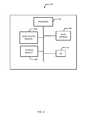
- FIG. 2is a block diagram of an example system that may employ the example digital video signature generation apparatus and methods described herein to identify video programs.
- FIG. 3is a more detailed block diagram of an example manner in which the data acquisition unit shown in FIG. 2 may be implemented.
- FIG. 4is an example processor-based system that executes software or instructions stored on a machine readable medium to implement the example data acquisition unit shown in FIG. 2 with the blocks shown in FIG. 3 .
- FIG. 5is flow diagram depicting one manner in which the processor-based system shown in FIG. 4 may be programmed to implement the example data acquisition unit shown in FIG. 3 .
- FIG. 6is an example of an image or frame for which a signature can be generated using a center of mass or centroid calculation.
- FIG. 7depicts an example image or frame in which image components are distributed in a non-uniform manner.
- FIG. 8depicts an example image in which a centroid is located within a shape boundary.
- FIGS. 9 and 10depict example images or frames in which centroids are not located within the boundary of the shapes therein.
- FIGS. 11 and 12are example images or frames that contain relatively symmetric distributions of a particular image component.
- FIG. 13depicts an example frame or image that contains three identical elliptical shapes composed of the same image component.
- FIGS. 14 and 15depict an example method that may be implemented by the system shown in FIG. 2 to identify video programs.
- the example video signature methods and apparatus disclosed hereincan be used to generate signature information for a sequence of images or frames composed of compressed digital video information.
- the generated signature informationmay subsequently be compared to reference signature information to identify a video program from which the sequence of images or frames originated.
- reference signature informationmay be compared to identify a video program from which the sequence of images or frames originated.
- MPEGMoving Pictures Expert Group
- the MPEG standardis one particularly well-known digital video compression standard that may be used in conjunction with the example signature generation methods and apparatus described herein.
- MPEG video compression techniquesare only one particular manner in which digital video information may be compressed prior to its use with the example signature generation methods and apparatus disclosed herein.
- Those having ordinary skill in the artwill appreciate that the example video signature apparatus and methods disclosed herein may be similarly applied in conjunction with other digital video compression schemes.
- video compression schemesoperate based on the assumption that video sequences or programs typically contain a relatively large amount of temporally and/or spatially redundant information.
- Temporal redundancyoccurs between successive frames or images making up a video sequence because there are relatively few changes to the color and brightness of large portions of the successive images or frames making up the video sequence.
- spatial redundancyoccurs within a given video frame or image because adjacent pixels or areas within an image or frame are often of the same or similar color and intensity or brightness.
- Compression ratiosare usually calculated by dividing the amount of video data making up an original sequence of video images by the amount of compressed data used to transmit that video data. Compression ratios of between about 8:1 and about 30:1 are commonly achieved using an MPEG-based video compression scheme.
- Video compression schemesalso typically eliminate certain types and amounts of video information that are not necessarily redundant and which may be eliminated without being perceptibly noticeable or offensive to the human eye.
- the human eyeis significantly more sensitive to variations in brightness than variations in color or hue.
- video compression schemesoften reduce the amount of digital information pertaining to color or hue without adversely impacting the perceived quality of an image extracted from compressed image information.
- the human eyehas greater difficulty perceiving rapid variation of brightness and/or color, shade or hue across an image (i.e., the higher frequency components that compose an image).
- video compression schemescan zero-out and/or eliminate the transmission or processing of the higher frequency components of an image without adversely impacting the perceived quality of the image.
- FIG. 1depicts an example sequence 100 of digital video images or frames 102 , 104 , 106 and 108 that may be associated with a digital television program or the like.
- the images or frames 102 - 108may make up a group of pictures (GOP) for purposes of MPEG encoding (i.e., compression) to be transmitted, stored or otherwise conveyed for use by an MPEG decoder associated with an output device (e.g., a television, video monitor, computer screen, etc.)
- GEPgroup of pictures
- each of the images or frames 102 - 108is composed of uncompressed digital information representing display pixels arranged in a plurality of rows and columns to be displayed on an output device in a particular format at a particular rate.
- each of the frames 102 - 108may contain sufficient pixel information to display images or frames on a raster scan-based display having 480 rows or lines of 720 pixels (i.e., columns) at a rate of 30 frames per second.
- a raster scan-based displayhaving 480 rows or lines of 720 pixels (i.e., columns) at a rate of 30 frames per second.
- many other display formats and ratescould be used instead.
- the amount of digital data required to represent each pixel within each of the frames or images 102 - 108depends on the color model used to create the images 102 - 108 .
- the color model used to create the images 102 - 108For example, in the case where the well-known Red, Green, Blue (RGB) color model is used, eight bits are used to represent the amount of each image or color component used for each pixel. Thus, for a digital image generated using the RGB color model, a total of twenty-four bits of data are required to represent each pixel.
- RGBRed, Green, Blue
- each of the images or frames 102 - 108is ultimately sub-divided into a sequence of macro blocks, each of which is composed of 16 ⁇ 16 pixels (i.e., sixteen rows of sixteen pixels).
- the resulting sequences of macro blocksare maintained in a raster scan order.
- the image or frame 104is sub-divided into a sequence of macro blocks 110 that is composed of at least macro blocks 112 , 114 , 116 and 118 , each of which includes RGB data for 16 ⁇ 16 or 256 pixels.
- the MPEG compression processconverts the RGB data (i.e., the twenty-four bits of information) for each pixel within the macro blocks 112 - 118 into the well-known YUV color model.
- the YUV color modelrepresents each pixel using a luminance value denoted as Y and two chrominance values denoted as Cr and Cb.
- the MPEG compression processdecimates the chrominance information for each of the macro blocks via a horizontal and vertical (i.e., row and column) sub-sampling process.
- the decimation processaverages the chrominance information (i.e., the Cr and Cb values) for groups of four pixels arranged in two rows and two columns, discards the individual chrominance values making up the averages and retains the average values.
- the MPEG compression processcompresses the chrominance information required to display an image by a factor of four without adversely affecting the perceptible quality of the image when displayed to a human.
- the macro block 118includes four 8 ⁇ 8 luminance blocks 120 , 122 , 124 and 126 and two 8 ⁇ 8 chrominance blocks 128 and 130 , together representing the color and intensity of the group of 16 ⁇ 16 pixels associated with the macro block 118 .
- Each of the blocks 120 - 130is composed of eight rows and eight columns of eight bit values (i.e., bytes).
- the luminance block 126is composed of a grid 132 where each of the squares of the grid 132 represents an eight bit luminance value associated with a particular pixel within the macro block 118 .
- each of the eight bit values within the 8 ⁇ 8 chrominance blocks 128 and 130represents the average color information for a group of four pixels associated with the macro block 118 .
- the MPEG compression schemeAfter converting the color model and decimating the chrominance information, the MPEG compression scheme processes the images or frames 102 - 108 , which are now represented using the decimated YUV data, to eliminate or reduce temporal redundancy.
- the MPEG compression schemeuses motion-compensated inter-frame prediction to reduce the amount of data required to regenerate a sequence of video frames.
- the MPEG compression schemeperiodically generates reference frames (known as Intra-frames or I-frames) that are essentially still video images that can be regenerated (i.e., displayed) without reference to any other frames or images.
- a series of video frames preceding and/or following a reference frame or I-frameare either Predictive-frames (commonly known as P-frames) or Bidirectionally predictive-frames (commonly known as B-frames).
- P-framescontain motion vectors and error information relating the P-frame to an I-frame or to a preceding P-frame
- B-framescontain motion vectors and error information relating to preceding and/or subsequent I-frames or P-frames.
- the amount of information needed to represent each P-frame and B-framecan be significantly less than the amount of information needed to represent an I-frame.
- each of the frames or images 102 - 108 making up the video sequence 100are designated by the MPEG encoder as one of an I-frame, a P-frame or a B-frame.
- the relatively complex manner in which the MPEG compression process designates frames as I-frames, P-frames and B-framesis well-known in the art and is not described in further detail herein.
- the creation of P-frames and B-framesoccurs on a block-by-block basis (i.e., one macro block at a time).
- the MPEG compression schemeprocesses these frames to remove spatial redundancy.
- the MPEG compression schemerecognizes that within a given 16 ⁇ 16 pixel macro block there is typically a repeatable pattern of pixel information and/or the pixel information does not vary significantly (e.g., perceptibly) across the macro block.
- the MPEG compression schemeuses a discrete cosine transform (DCT) to convert each of the 8 ⁇ 8 blocks making up the macro blocks of the I-frames, P-frames and B-frames from the spatial domain into the frequency domain.
- DCTdiscrete cosine transform
- each square (i.e., byte) within an 8 ⁇ 8 blockcorresponds to a physical pixel location
- each square within the 8 ⁇ 8 block produced by the DCT conversioncorresponds to a frequency of a cosine waveform.
- the upper left corner of the frequency domain blockis a DC value (e.g., the average luminance for the 8 ⁇ 8 spatial domain block), and the horizontal frequency increases moving across rows to the right of the upper left corner and the vertical frequency increases moving down columns.
- the upper left corner of the frequency domain blocki.e., the DC coefficient value
- the upper left corner of the frequency domain blockalso represents the value associated with the pixel in the upper left corner of the block in the spatial domain.
- frequency coefficients within the frequency domain block other than the DC coefficientdo not correspond identically to pixel values in the spatial domain.
- a conversion of the frequency domain block to spatial domainis required.
- performing a DCT and quantization on each of the 8 ⁇ 8 blocksresults in frequency domain blocks having relatively few coefficient values near the upper left corner of the 8 ⁇ 8 frequency domain blocks and a relatively large number of zero value or same value coefficients in the majority of the squares making up the remainders of the blocks.
- the MPEG compression processcan substantially reduce the amount of data needed to reconstitute the compressed image without perceptibly degrading the image quality.
- an 8 ⁇ 8 block of pixel luminance informationsuch as, for example, the block 126 of FIG. 1 .
- the luminanceis constant (e.g., a digital value of 128) across the block 126 .
- each of the luminance values associated with the 64 squares making up the grid 132will contain the value 128 .
- Performing a DCT on such an 8 ⁇ 8 blockwill result in an 8 ⁇ 8 block in which the upper left corner square contains the DC value 128 and all other squares or frequency domain coefficients are equal to zero.
- the frequency domainonly a single value needs to be used (and transmitted) to represent the luminance values for all of the pixels associated with the original 8 ⁇ 8 spatial domain block.
- 63 eight bit luminance valuesdo not have to be transmitted and processed by an MPEG decoder. Instead, using a run-length encoding scheme, a single value (i.e., 128) may be transmitted and a run length of 63, (indicating 63 zeros), may be transmitted to the MPEG decoder.
- the MPEG compression processachieves relatively high compression ratios by employing techniques such as, for example, frequency coefficient quantization (e.g., reducing the number of bits needed or allocated for each frequency domain coefficient), and zigzag sequence coding in conjunction with run-length encoding to eliminate the individual transmission of coefficients having the same value.
- frequency coefficient quantizatione.g., reducing the number of bits needed or allocated for each frequency domain coefficient
- zigzag sequence codingin conjunction with run-length encoding to eliminate the individual transmission of coefficients having the same value.
- FIG. 2is a block diagram of an example system 200 that may employ the example digital video signature generation apparatus and methods described herein to identify video programs.
- the system 200includes a demodulator 202 that receives a digital program data stream 204 .
- the digital program data stream 204may be a multi-program data stream that is broadcast via any desired method.
- the digital program data stream 204may be a multi-program digital television data stream that is broadcast using any desired combination of wireless communication links such as, for example, satellite communication links, cellular communication links, or other wireless terrestrial communication links.
- the digital program data stream 204may be transmitted via any desired combination of hardwired communication paths including cables, phone lines, etc.
- the example digital program data stream 204is assumed to include one or more digital video programs that have been compressed and formatted according to the MPEG standard as described by way of example in connection with FIG. 1 .
- the MPEG packets making up the video frame or image information for each of the digital video programsmay be encapsulated using any desired transport protocol.
- the demodulator 202may extract a base band signal containing a multi-program digital data stream and a transport circuit for reconstructing data packets associated with a desired program from the digital program data stream 204 .
- the demodulator 202When the demodulator 202 is tuned to a particular channel, it reconstructs the MPEG data packets from the digital program data stream 204 that corresponds to the selected program.
- the system 200also includes a data acquisition unit 206 that is coupled to the demodulator 202 .
- the data acquisition unit 206selects compressed digital video information 208 (e.g., MPEG I-frames, P-frames and B-frames) associated with a video program currently output by the demodulator 202 .
- compressed digital video information 208e.g., MPEG I-frames, P-frames and B-frames
- the data acquisition unit 206selects frames or images from the compressed digital video information 208 that are substantially intra-coded (i.e., frames or images containing a substantial percentage of intra-coded macro blocks) and generates signature information for the video program based on those substantially intra-coded frames or images.
- the data acquisition unit 206extracts scaled image information (e.g., by extracting the DC coefficient information) from the selected substantially intra-coded frequency domain blocks and uses the scaled image information to calculate center of mass or centroid information for each of the brightness and color components for each of a series of the substantially intra-coded images or frames.
- scaled image informatione.g., by extracting the DC coefficient information
- Each of the images or framesmay also be recursively sub-divided into a plurality of sub-regions or areas and center of mass information may be similarly generated for each of the sub-regions or areas.
- each substantially intra-coded frame or imagecan be substantially uniquely represented by a signature composed of a plurality of centers of mass or centroid values associated with the components (e.g., colors, brightness, etc.) of the overall image or frame and any defined sub-regions or areas of the image or frame.
- the data acquisition unit 206is communicatively coupled to a central processing unit 210 via a communication link 212 .
- the communication link 212may be implemented using any desired combination of hardwired and wireless communication links and any desired combination of communication protocols or schemes.
- the communication link 212may be implemented as a local area network, or any other network, and/or may include the use of phone lines, a packet switched network such as, for example, the Internet, or any other types of communication links.
- the central processing unit 210also includes a non-volatile memory or mass storage device 214 .
- the memory or mass storage device 214may be implemented using, for example, a disk drive that stores digital information using a magnetic or optical media. Additionally or alternatively, the memory or mass storage device 214 may be implemented using an electrically erasable programmable read only memory (EEPROM) or the like.
- EEPROMelectrically erasable programmable read only memory
- additional data acquisition units similar or identical to the data acquisition unit 206may be communicatively coupled to the central processing unit 210 .
- the data acquisition unit 206sends signatures generated (as generally set forth above) in connection with a sequence of video images or frames associated with a currently selected video program to the central processing unit 210 via the communication link 212 .
- the central processing unit 210is configured to compare the sequence of signatures received from the data acquisition unit 206 to a plurality of known or reference signatures that are associated with known video programs and which are stored within a data structure (e.g., a table) within the non-volatile memory 214 . In the event that the central processing unit 210 determines that a signature sequence received from the data acquisition unit 206 matches or substantially matches a reference signature sequence associated with a known video program, the central processing unit 210 identifies the video program selected by the demodulator 202 .
- the demodulator 202 and the data acquisition unit 206may be located within a private home or other residence or, alternatively, may be located within a business facility or any other structure.
- the system 200is located so that the broadcast signals that are to be consumed and/or verified can be easily detected and received.
- other such decoders and data acquisition unitsmay be similarly located within other locations and communicatively coupled to the central processing unit 210 via the communication link 212 and/or via other communication links (none of which are shown). In this manner, statistically significant viewing behavior and/or program verification information for a designated population of persons or geographic area may be ascertained by the central processing unit 210 .
- the system 200may further include a central facility 216 that communicates with the central processing unit 210 via a communication link 218 , which may be implemented using a wide area network including phone lines, wireless communications and/or any other desired communication media and/or protocols.
- the link 218may be implemented using a wide area network including phone lines, wireless communications and/or any other desired communication media and/or protocols.
- the central facility 216may process signature information and/or other program-related information received from the central processing unit 210 and/or other processing units (none of which are shown). For example, in the event that the central processing unit 210 fails to identify a program, video clip, etc., using signature information, that signature information and the associated video clip may be conveyed to the central facility 216 via the link 218 .
- the signature informationmay be compared to signatures stored within a library of signatures within (or at least accessible to) the central facility 216 .
- a signature librarymay be complied by receiving signature information from a variety of sources such as, for example, other central processing units (not shown) and/or data acquisition units (not shown). Additionally or alternatively, if the signature information received by the central facility 216 does not match any of the signature information already present in the library accessible to or within the central facility 216 , the program, video clip, etc. associated with the signature information is viewed and identified by a human operator. The human operator may then add a signature for that program, video clip, etc. to the signature library.
- the functions of the data acquisition unit 206may instead be integrated within the demodulator 202 or the central data processing unit 210 .
- the functions of the data acquisition unit 206could be distributed between the demodulator 202 , the central processing unit 210 and/or other similar or identical units within or at least accessible by the system 200 .
- FIG. 3is a more detailed block diagram of an example manner in which the data acquisition unit 206 shown in FIG. 2 may be implemented.
- the example data acquisition unit 206includes a frame scanner 300 that receives the compressed digital video information 208 , which contains frequency domain image information, and scans the individual images or frames (i.e., I-frames, P-frames, B-frames, etc.) therein to determine, for each image or frame, whether that image or frame contains a sufficient quantity of intra-coded macro blocks for subsequent processing by the remaining functional blocks of the data acquisition unit 206 .
- the compressed digital video information 208which contains frequency domain image information
- the individual images or framesi.e., I-frames, P-frames, B-frames, etc.
- the frame scanner 300selects frames or images having a relatively high percentage of intra-coded macro blocks to enable the data acquisition unit 206 to generate signature information for those selected images or frames using a relatively small amount of processor time (i.e., processing cost or overhead).
- processor timei.e., processing cost or overhead
- intra-coded macro blocksmay be converted to image information without having to perform complex time consuming calculations involving macro block information from future or subsequent frames or images. Accordingly, by selecting images or frames having a relatively high percentage of intra-coded blocks, the data acquisition unit 206 can generate signatures rapidly and with minimal error for those selected images or frames using only the intra-coded blocks.
- I-framesare always sufficiently intra-coded and P-frames and B-frames may be sufficiently intra-coded depending on the amount of intra-coded macro blocks that are used to generate these frames.
- the intra-coded block extractor 302extracts intra-coded macro blocks from a selected frame or image, which may be an I-frame or a predictive frame (e.g., P-frame or B-frame) having a relatively high percentage of intra-coded macro blocks.
- a selected frame or imagewhich may be an I-frame or a predictive frame (e.g., P-frame or B-frame) having a relatively high percentage of intra-coded macro blocks.
- a scaled image extractor 304receives the intra-coded blocks extracted from a selected frame or image and extracts a downscaled image, for example, by extracting DC coefficients (i.e., the upper left corner values) from the intra-coded blocks.
- DC coefficientsi.e., the upper left corner values
- the macro blocks making up an image or frameare passed through a DCT conversion and quantization that provides spatially compressed frequency domain macro block information.
- a downscaled imagemay be formed using other combinations of frequency coefficients.
- the DC coefficients and coefficients associated with one or more other frequency components, such as coefficients in the upper left corner of macro blocks,may be extracted.
- the scaled image extractor 304in contrast to a case where only DC coefficients are extracted, the scaled image extractor 304 generates the downscaled image by converting the frequency domain blocks to spatial domain pixel information.
- the scaled image extractor 304extracts downscaled images by extracting a subset of the frequency coefficients available in each intra-coded frame provided by the intra-coded block extractor 302 , thereby substantially reducing the amount of information that has to be processed to generate signature information, and convert that frequency domain information to spatial domain pixel information.
- the conversion of frequency domain information to spatial domain informationis not necessary (and may be eliminated) because the DC coefficients in the frequency domain also correspond to pixel values (i.e., the upper left pixels in blocks) in the spatial domain.
- the scaled image extractor 304extracts the downscaled image information (e.g., the average luminance and chrominance values in the case where DC coefficients are extracted) from the intra-coded macro blocks and passes those downscaled images to a padding remover 306 .
- the number of frequency coefficients used to form the downscaled imagemay be based on the resolution of the image being downscaled.
- high resolution imagesmay be downscaled using only DC coefficients, whereas, lower resolution images may require the extraction of a plurality of frequency coefficients from each frequency domain block to form the downscaled image.
- the higher the resolution the image being downscaledthe fewer the number of frequency coefficients that are required to form a downscaled image suitable for signature generation purposes.
- the padding remover 306removes coefficients that are associated with padded image or frame areas.
- digital video images or framesmay be padded (i.e., filled with known video information) to completely fill the display area of a video frame or image.
- border areas of a displayed image or frame for which image information may not existcan be filled with a consistent color and/or intensity to provide a visually acceptable border.
- display areas for which image information is not availablemay be filled with a dark or gray border as opposed to allowing noise or other random video information to be displayed in these display areas.
- paddingis added to the image so that the left and right sides of the displayed image are flanked by solid colored borders or bands.
- such paddingis not a part of the original image and is typically a function of the particular encoder.
- the scaled image informationis provided to a signature generator 308 .
- the signature generator 308uses the extracted scaled image information to generate image signatures based on the centers of mass or centroids of the various color and brightness components of an overall image and sub-images or areas defined within that overall image.
- each imagecan be described by a signature composed of a set of centroid coordinates that is substantially uniquely characteristic of the distribution of color and brightness within that image.
- a series of such signatures associated with a series or sequence of video frames or imagescan be used to uniquely represent and/or identify a video program from which the video frames or images were extracted.
- Signature information 310which is a sequence of signatures of frames or images associated with and uniquely representative of a selected video program, is conveyed to, for example, the central processing unit 210 ( FIG. 2 ). As described in greater detail below, the central processing unit 210 is configured to compare the received signature information 310 to reference signature information (e.g., sets of signature sequences representative of known video programs) to determine the identity of a video program currently selected by the demodulator 202 ( FIG. 2 ).
- reference signature informatione.g., sets of signature sequences representative of known video programs
- FIG. 4is an example processor-based system 400 that executes software or firmware instructions stored on a machine readable medium to implement the data acquisition unit 206 ( FIG. 2 ).
- the example processor-based system 400includes a processor 402 , which may be any suitable microprocessor such as, for example, a processor from the Intel Pentium® family of microprocessors.
- the processor 402may be communicatively coupled to a non-volatile memory 404 and a volatile memory 406 .
- the non-volatile memory 404may be implemented using, for example, electrically erasable programmable read only memory (EEPROM), read only memory (ROM), etc.
- the volatile memory 406may be implemented using, for example, static random access memory (SRAM), dynamic random access memory (DRAM), etc.
- the processor 402may also be coupled to a mass storage device 408 , which may be implemented using, for example, a disk drive that stores digital information using a magnetic or optical media.
- the processor 402can retrieve and execute machine readable instructions or software programs that are stored on one or more of the memories 404 and 406 and/or the mass storage device 408 to perform the functions of the data acquisition unit 206 ( FIG. 2 ) and, in particular, the functions of the blocks 300 - 308 shown in FIG. 3 .
- the processor 402is also in communication with an input/output (I/O) unit 410 , that enables the system 400 to communicate with, for example, the demodulator 202 ( FIG. 2 ) and/or the central processing unit 210 ( FIG. 2 ).
- the I/O unit 410may include circuitry for performing network communication functions (e.g., Ethernet communication functions), phone line communication functions (e.g., modem functions), peripheral device communication functions (e.g., universal serial bus communications, parallel port communications, etc.) to enable the system 400 to communicate with one or more input devices such as, for example, a mouse, keyboard, etc. and/or one or more output devices such as, for example, a video display, a printer, etc.
- network communication functionse.g., Ethernet communication functions
- phone line communication functionse.g., modem functions
- peripheral device communication functionse.g., universal serial bus communications, parallel port communications, etc.
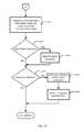
- FIG. 5is flow diagram depicting one manner in which the processor-based system 400 shown in FIG. 4 may be programmed to implement the example data acquisition unit 206 ( FIG. 2 ).
- the blocks 300 - 308 ( FIG. 3 ) of the example data acquisition unit 206 ( FIG. 2 )may be implemented using any desired combination of hardware and software.
- the data acquisition unit 206may include one or more application specific integrated circuits, microprocessors executing machine readable instructions, digital logic components, analog circuitry, etc. configured to operate as blocks 300 - 308 .
- the data acquisition unit 206receives a compressed digital video frame or image from the demodulator 202 (block 500 ).
- the compressed video frames or images received by the data acquisition unit 206are compressed using the well-known MPEG standard.
- any other compression standards or techniques yielding scaled image information (e.g., downscaled images) for the frames or imagescould be used instead.
- the received compressed digital video frame or imageis scanned to determine the number or percentage of intra-coded macro blocks of which the frame or image is composed (block 502 ).
- the processor 402determines if the frame or image includes a sufficiently high percentage of intra-coded macro blocks (block 504 ).
- the percentage constituting a sufficient percentagemay vary depending on the particular application. For example, if a very low program identification failure rate is acceptable, it may be desirable to generate signatures only for entirely intra-coded frames (I-frames or other frames that contain 100% intra-coded blocks) to maximize the amount of image information that can be used to generate the signature information for the frames or images. On the other hand, if a higher program identification failure rate is acceptable, frames having a lesser percentage of intra-coded blocks may be sufficiently intra-coded.
- the processor 402awaits another frame or image at block 500 .
- the processor 402extracts the downscaled image information (e.g., the values of the DC coefficients) from the frequency domain macro blocks making up the image or frame (block 506 ).
- the extraction of the downscaled image at block 506may also include a conversion to spatial domain pixel information in the case where frequency domain coefficients other than just the DC coefficient values are extracted from each frequency domain block.
- the processor 402then removes image information or image areas associated with padding such as, for example, borders or other image portions inserted to enable an image that may not properly fill a display area to be displayed in an unobjectionable manner (block 508 ). In this manner, the processor 402 can generate signature information for the frame or image in a manner that does not include any video information that is not part of the original image.
- the information representative of the image(i.e., the downscaled image containing selected pixel information), from which padding has been removed, may optionally be weighted (block 510 ).
- the processor 402may weigh the downscaled image information (e.g., by multiplying each of the pixel values by a number ranging from zero to one) to improve the robustness of the signature generation process. For example, the processor 402 may weigh the pixel values associated with the center portions of an image or frame more heavily (e.g., using a multiplier closer to one) than those portions of the image or frame that are closer to the periphery of the image or frame.
- Weighting the central portion of an image more heavily than the peripheral portions of an imagemay significantly reduce or eliminate signature generation errors that may otherwise result in the event an image has been cropped at its periphery from its original form. In other words, cropping a portion of an image that is given little, if any, weight during the signature generation process will have little, if any, effect on the accuracy of the signature generation process.
- the processor 402then generates the signature information using the downscaled information from those frames or images that are sufficiently intra-coded (block 512 ). As described above, certain image areas may be removed prior to the signature generation process (block 512 ) such as, for example, those areas associated with padding (block 508 ). In addition, some or all of any remaining areas may be weighted (block 510 ) prior to the signature generation process (block 512 ).
- the processor 402may locally store the signature on the mass storage device 408 and/or the volatile memory 406 (block 514 ). The processor 402 may then send signatures and downscaled image information as it is generated (block 512 ) and stored (block 514 ) or, alternatively, periodically in sets or groups of signatures, to the central processing unit 212 (block 516 ) for matching analysis and program identification. After generating each signature (block 512 ) and any storing and sending activities (blocks 514 and 516 ), the processor 402 waits for another image or frame (block 500 ).
- the data acquisition unit 206( FIG. 2 ) generates video signatures by calculating the centroids or centers of mass for each of the image color components (e.g., Red, Green, Blue, Yellow, etc.) and brightness components (e.g., Black/White).
- each center of mass or centroidis calculated using a downscaled image (e.g., a subset of the frequency coefficients and, thus, a subset of spatial domain pixel values) extracted from each of the frequency domain macro blocks making up an image or frame.
- a downscaled imagee.g., a subset of the frequency coefficients and, thus, a subset of spatial domain pixel values
- certain areasmay be eliminated if associated with padding and/or may be weighted to reduce or eliminate the effects of image cropping.
- the center of mass calculations or centroid calculationssum the moments of the downscaled image pixel values.
- the horizontal (e.g., x-axis) position within the frame or image for an image component center of mass or centroidthe value for each pixel is multiplied by its column number within its associated image or frame, the individual moments are summed, and the sum is divided by a maximum column moment value to provide a normalized horizontal position for the center of mass or centroid for that image component.
- the value for each pixelis multiplied by its row number within the frame, the individual moments are summed, and the sum is divided by a maximum row moment value to provide a normalized vertical position for the center of mass or centroid for that image component.
- the normalized horizontal and vertical positions of the centroid for an image componenti.e., a particular color or brightness
- Ican be expressed as a percentage using Equations 1 and 2 below.
- Equations 1 and 2the value “C” is the total number of columns (e.g., the number of pixels per line) within the image or frame for which the signature is being calculated, the value “R” is the total number of rows (e.g., lines), and the values I[r][c] are the values for the pixel at row “r” and column “c” for component “I” (e.g., Red, Green, Blue, Yellow, brightness, etc.).
- component “I”e.g., Red, Green, Blue, Yellow, brightness, etc.
- images or framesmay be weighted to eliminate or reduce the effects of cropping and the like.
- the values I[r][c]i.e., the downscaled image pixel values
- the above centroid or center of mass calculationsare normalized. Using normalized centroid information to generate signatures for images or frames or sequences of signatures for a video sequence can reduce or eliminate the effects of image scaling, shifting, etc.
- FIG. 6is an example of an image or frame 600 for which a signature can be calculated using the method described above in connection with Equations 1 and 2.
- the image or frame 600includes four circles 602 , 604 , 606 and 608 , each of which is a pure color within a particular color model.
- the circles 602 - 608may be red, green, blue and yellow, respectively.
- the colored circles 602 - 608are of equal and uniform brightness.
- Equations 1 and 2 aboveto generate the normalized horizontal and vertical coordinates for the centroids or centers of mass for each of the colors and brightness components of the image 600 results in the set of coordinate pairs (X 1 , Y 1 ), (X 1 , Y 3 ), (X 2 , Y 2 ), (X 3 , Y 1 ), and (X 3 , Y 3 ).
- the pair (X 1 , Y 1 )is the centroid of the color component associated with the circle 608
- (X 1 , Y 3 )is the centroid of the color component associated with the circle 606
- (X 2 , Y 2 )is the centroid of the brightness associated with the image 600
- (X 3 , Y 1 )is the centroid of the color component associated with the circle 602
- (X 3 , Y 3 )is centroid of the color component associated with the circle 604 .
- the set of normalized coordinate pairs for the centroids or centers of mass of the various color and brightness components that combine to compose the image or frame 600are substantially uniquely representative of the image 600 . For instance, moving only the circle 602 horizontally toward the right of the image 600 will significantly affect the horizontal component of the centroid for the circle 602 (e.g., the value X 3 will move accordingly).
- the set of normalized coordinate pairs for the image 600can be used in several manners to define a signature for the image 600 .
- the signature for the image 600may be defined as a collection or set of the centroid coordinate pairs for each component color and/or brightness making up an image.
- a signature based on the normalized coordinates of the color and brightness image componentscan be formed using relative position information between two or more of the image components.
- a signaturecan be formed using vectors or relative movement or location information for several image components based on the absolute normalized coordinates for one image component.
- the absolute coordinates for the centroid of the color component redare used (i.e., X 3 , Y 1 )
- the positions of the remaining componentsare described relative to red and one another and follow a path 610 within the image 600 .
- the position of the centroid for the green componentcan be defined relative to the red component, the position of the centroid for the blue component relative to the green component, the position of the centroid for the yellow component relative to the blue component and the position of the brightness component relative to the yellow component.
- the delta X and Y valuesrepresent horizontal and vertical displacements from the horizontal and vertical positions of the preceding centroid within the set of centroid positions making up the signature “S.”
- the absolute coordinates for the position of the centroid of the red componentare not included to provide a signature that is not sensitive to shifting or movement of an entire image within the frame 600 .
- a signature generation technique based on relative centroid positionssuch as that provided by Equation 3 above
- a displacement of all four of the circles 602 - 608 by the same horizontal and vertical distances within the frame 600will not affect the signature generated (i.e., the relative centroid coordinates or positions will not change).
- the positions of one or more of the signature components signaturemay be generated based on the position of the image component centroid with respect to a predetermined or fixed reference point.
- example image 600 of FIG. 6is described as being based on a color model having red, green, blue, yellow and brightness components, other color models and, thus, image components could be used instead.
- image componentsincluding, for example, RGB, HIS, YUV, YCrCb, CIELAB and the like may be used in conjunction with the example methods and apparatus disclosed herein.
- image informationmay be received by the data acquisition unit 206 ( FIG. 2 ) in a form based on one color model and converted to another color model to facilitate and/or improve the signature generation process.
- the data acquisition unit 206may receive MPEG image information from the demodulator 202 .
- MPEG images or framesare formed using a YUV or YCrCb color model.
- signature generation(block 512 of FIG. 5 ) the data acquisition unit 206 may convert the luminance and chrominance information provided by the YCrCb or YUV models to provide color information for red, green, blue, yellow and brightness components. Because the relationships between the different color models are well known, a detailed description of such a conversion process is not provided herein.
- non-normalized centroid informationmay be used as well.
- the use of non-normalized centroid informationmay result in increased sensitivity to image scaling and the like, which may result in a higher probability of failing to identify or falsely identifying an image or sequence of images (e.g., a video program).
- the distribution of componentse.g., colors, brightness, etc.
- the color components composing the frame 600are represented as non-overlapping, symmetrically distributed circles.
- most images or frames making up a video programare composed of a significantly more complex distribution of color and brightness components than the simplified case shown in FIG. 6 .
- FIG. 7depicts an example image or frame 700 in which three image components (e.g., three colors of a color model) are distributed in a more complex non-uniform manner.
- the image 700is shown as three component layers 702 , 704 and 706 in which each image component is distributed in a non-uniform manner.
- the layer 702may be a red layer
- the layer 704may be a green layer
- the layer 706may be a blue layer having respective centroids or centers of mass (X 1 , Y 1 ), (X 2 , Y 2 ) and (X 3 , Y 3 ).
- the signature generation technique described above in connection with FIG. 6 and Equations 1, 2 and 3may similarly be applied to images having more complex component distributions such as the image 700 of FIG. 7 .
- FIG. 8depicts a frame or image 800 having a circle 802 of a pure color component (e.g., red, green, blue, etc.)
- the circle 802has a centroid 804 located at the “+” at the center of the circle 802 .
- FIG. 9depicts an example frame or image 900 having two circles 902 and 904 of a pure color component the same as that composing the circle 802 of the image 800 .
- a centroid 906 for this color component of the image 900is located at the “+.”
- FIG. 8depicts a frame or image 800 having a circle 802 of a pure color component (e.g., red, green, blue, etc.)
- the circle 802has a centroid 804 located at the “+” at the center of the circle 802 .
- FIG. 9depicts an example frame or image 900 having two circles 902 and 904 of a pure color component the same as that composing the circle 802 of the image 800 .
- FIGS. 8 and 9depicts another example frame or image 1000 having a ring-shaped object 1002 composed of the same color component as that composing the circles 802 , 902 and 904 of FIGS. 8 and 9 .
- a centroid 1004 for this color component of the image 1000is identically positioned within the image 1000 as the centroids 804 and 906 are positioned within the images 800 and 900 .
- the centroids for a particular color component for three substantially different distributions of that color componentare all identically positioned within their respective images or frames and, thus, cannot be used to uniquely distinguish between the images 800 , 900 and 1000 .
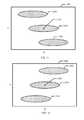
- FIGS. 11 and 12are example frames or images 1100 and 1200 that contain relatively symmetric distributions of a particular component.
- the frame 1100contains three identical elliptical shapes 1102 , 1104 and 1106 , each of which is composed of a single component (e.g., a single color component).
- the center of mass or centroid of the component distribution shown in FIG. 11is located at (X 1 , Y 1 ), which is designated within the image 1100 using a “+” sign at reference numeral 1108 .
- FIG. 12also contains three elliptical shapes 1202 , 1204 and 1206 that are composed of the same component and are of the same shape and size as the shapes 1102 , 1104 and 1106 of FIG. 11 .
- the shapes 1202 , 1204 and 1206are distributed within the image or frame 1200 in a substantially different manner than the shapes 1102 , 1104 and 1106 are distributed within the frame 1100 , using Equations 1 and 2 above to generate a centroid for the component distribution within the frame 1200 yields a centroid location 1208 that is identical to the centroid location 1108 of the component distribution of FIG. 11 (i.e., X 1 , Y 1 ).
- a signature for a frame or imagecan be made more unique by sub-dividing the image or frame into a plurality or regions or areas, calculating the component centroids for these sub-divided regions or areas and forming a signature for the frame or image including component centroids for the overall image and the component centroids for the sub-divided regions or areas.
- a signature generated in this manneris less sensitive to the aforementioned problems discussed in connection with FIGS. 8-12 above.
- FIG. 13depicts an example frame or image 1300 that contains three identical elliptical shapes 1302 , 1304 and 1306 , all of which are composed of the same component (e.g., a single color).
- the image 1300has been sub-divided into four quadrants labeled Q0, Q1, Q2 and Q3.
- the centroid for the overall image 1300is located at the “+” designated by the reference numeral 1306 and the centroids for the quadrants Q0, Q1, Q2 and Q3 are designated by the “+” signs designated by respective reference numerals 1308 , 1310 , 1312 and 1314 , respectively.
- each image componente.g., a color or brightness component
- each image componentmay be represented using five centroids (i.e., five horizontal and vertical coordinate pairs or ten values), one of which corresponds to the overall image and the remaining four of which correspond to the four sub-images or regions.
- a set containing a total of twenty-five centroidsi.e., twenty five horizontal and vertical coordinate pairs or fifty values
- An example of such a signaturecan be represented as depicted in Table 4 below.
- sub-regionsmay be further sub-divided in a recursive manner to achieve any desired level of signature uniqueness.
- a greater number of sub-images or sub-divided areasmay be defined within an image or frame to generate a signature having a greater amount of distinguishing information.
- the sub-image areas or regionsdo not have to be identically shaped and sized.
- relatively smaller sub-divisions or sub-imagesmay be used within the central region of an overall image and relatively larger sub-divisions may be used within the peripheral regions of an image.
- signature generation example given in connection with FIG. 13uses normalized non-relative centroid coordinates or locations, relative centroid locations as discussed above may be used instead.
- Centroids calculated for frames or images having a constant value that is substantially greater than zerowill all be relatively stable and centered within the images.
- an entirely medium gray image and an entirely dark gray imagewill both result in centroids that are centered within the image, thereby making it impossible to distinguish these two images on the basis of their image component centroids.
- these types of imagescontain little, if any, information and may, for example, be perceived as blank images.
- An alternative signature generation techniquemay be employed for the images or frames that contain relatively constant information (e.g., the distribution of one or more image components is relatively uniform within the frames or images), such as those described above.
- block 512may generate the signature for the frame or image being processed using such an alternative signature generation technique.
- Equation 4does not provide an actual geometric centroid but, rather, a pair of coordinates that can be used to serve the function of a substantially unique coordinate pair for a relatively blank or uniform image.
- Equation 4uses Equation 4 to calculate representative coordinates for one image entirely filled with medium gray and another image entirely filled with dark gray will yield different pseudo-centroids or coordinate pairs that enable substantially unique signatures for these images to be formed.
- the image valuesmay be inverted (i.e., the image may be inverted so that the foreground (e.g., textual information) is relatively light and the background is relatively dark) so that the foreground has a much more significant effect on the centroid of the image.
- the pixel values associated with the inverted imageare then used to generate the centroid(s) and, thus, the signature for the image(s).
- the centroid valuesmay be negated (i.e., multiplied by ⁇ 1) to indicate that the centroid values correspond to an inverted image.
- the data acquisition unit 206receives video frames or images (e.g., compressed video or MPEG frames) from the demodulator 202 ( FIG. 2 ) and generates signatures and downscaled images for some or all of these received frames or images using, for example, the methods described above.
- the central processing unit 210is configured to compare sequences of signatures received from the data acquisition unit 206 ( FIG. 2 ) to reference sequences of signatures associated with known video programs (e.g., television commercials, television shows, etc.) to identify one or more selected programs and forward the unidentified video clip to the central facility 216 .
- the central processing unit 210receives signature information from the data acquisition unit 206 ( FIG. 2 ) (block 1400 ). The central processing unit 210 then determines whether the received signature information is the start or beginning of a sequence (block 1402 ). If the received signature information is the start of a sequence at block 1402 , the central processing unit 210 selects one or more reference signature sequences from a database or library of signature sequences (block 1404 ), which may be stored within the memory or mass storage device 214 ( FIG. 2 ), and appends the selected signature sequences to a dynamic accumulation table or intermediate results table. On the other hand, if the central processing unit 210 determines at block 1402 that the received signature information is not the start of a sequence, then control is passed to block 1406 .
- signature sequencesmay be represented as [S A ][S B ][S C ][S D ] . . . , where S A is a first signature (e.g., a set of image component centroids generated as set forth above) for a frame or image, S B is another signature (e.g., another set of image component centroids) associated with a subsequent frame or image, etc.
- S Ais a first signature (e.g., a set of image component centroids generated as set forth above) for a frame or image
- S Bis another signature (e.g., another set of image component centroids) associated with a subsequent frame or image, etc.
- one useful manner of selecting candidate or reference signature sequences (block 1404 ) in a case where the initial signature received at block 1400 is S Ais to select all signature sequences from the database or library of known signature sequences that include the signature S A within a predetermined number of signatures from the beginning of the sequence.
- the signature sequences listed below in Table 2if in the database or library, may be selected at block 1404 and appended to the accumulation or intermediate results table.
- the selected signature sequencesdo not necessarily begin with the signature S A but, instead, include the signature S A . From the example group of selected signature sequences shown in Table 2, only signature sequences including the signature S A within the first three signatures may have, for example, been selected.
- the central processing unit 210updates match results for each of the reference signature sequences (block 1408 ) in the accumulation or intermediate results table.
- the match resultstrack, for each reference sequence of signatures, if the individual signatures within a sequence of signatures generated by the data acquisition unit 206 ( FIG. 2 ) match corresponding signatures within the reference sequences of signatures.
- the match resultscan be represented within a table in which each row of the table corresponds to a different reference signature sequence and each column of the table corresponds to a relative temporal position within the sequence.
- Table 3 belowis an example table that represents the match results after having received the signatures S A and S F .
- the value “1”indicates a match occurred at block 1406 , the value “0” indicates a match did not occur and “X” indicates a position within the sequence that has not yet been tested (i.e., compared to a signature received from the data acquisition unit 206 ).
- the processing unit 210then eliminates non-matching reference signature sequences from the accumulation or intermediate results table (e.g., from Table 2). For example, sequence number two may be eliminated for having at least one non-matching signature. However, in some cases it may be desirable to only eliminate sequences having two non-matching signatures or a greater number of non-matching signatures. For this example, only sequences having three or more non-matching signatures are eliminated at block 1410 . As a result, only signature sequence six is eliminated following the receipt and processing of the second signature S F .
- each of the remaining signature sequenceshas at least two untested positions.
- the processing unit 210will loop through blocks 1400 - 1420 at least two additional times. If the signatures S G and S N are received as third and fourth signatures, respectively, no additional comparisons will be required at block 1406 after receiving the signature S N (i.e., there are no untested sequence positions at that point).
- Table 4the state of the match results for the above example is as depicted in Table 4 below.
- signature sequences one, two, three and sixhave been eliminated following the receipt of the signature S N because these sequences contained at least three non-matching signatures upon receipt of the signature S N .
- the central processing unit 210examines the match results to determine if there is a matching sequence (block 1414 ).
- signature sequence fiveis an identical match and, thus, is a matching sequence.
- the processing unit 210may consider a substantial match (i.e., a non-identical match) sufficient.
- the processing unit 210may consider three out of four matches for a signature sequence to be a matching sequence.
- the central processing unit 210may consider the reference signature sequence having the greatest number of matching signatures to be a matching sequence, regardless of the percentage of matching signatures.
- the central processing unit 210may, based on historical information, identify the matching reference sequence of signatures as that sequence that occurs most frequently (i.e., the most probable sequence of signatures). More generally, the number or percentage of matching signatures required to satisfy a matching condition depends on what level of inaccurate video program identification is acceptable for a particular application. In other words, if a relatively low level of inaccurate video program identification is acceptable, then a lower percentage or number of matching signatures may be acceptable to satisfy a match condition. On the other hand, if a relatively high level of inaccurate video program identification is acceptable, then a higher percentage or number of matching signatures may be acceptable to satisfy a match condition.
- the central processing unit 210determines that a signature sequence match has been found at block 1414 , the central processing unit 210 then identifies the video sequence or program associated with the matching reference signature sequence (block 1416 ). Any desired data structures and/or database search techniques may be used. For example, once a matching sequence of signatures has been identified, the sequence number or identifier associated with the matching sequence of signatures may be used to access (e.g., via an indexing or lookup method) textual information associated with the audio and/or video program corresponding to that identifier or sequence number. Alternatively, a set of tables organized in a linked tree-like data structure may be used.
- each of the tablesmay be indexed using centroids or coordinate pairs (e.g., horizontal and vertical coordinates).
- centroids or coordinate pairse.g., horizontal and vertical coordinates.
- a first coordinate pair or centroid associated with a signatureis used to index to a link to a subsequent table.
- the next coordinate pair of the signatureis then used to index within the subsequent table to another table.
- This processcontinues until all coordinate pairs associated with all of the signatures within a signature sequence have been exhausted at a final table.
- the last coordinate pairis then used to index to textual information (e.g., in the form of metadata) describing the video program associated with the sequence of signatures information (i.e., sequence of centroids or coordinate pairs used to index through the linked tables).
- a searchable tree-like data structuresuch as that described above provides a relatively short search time.
- the video programs being identifiedare television commercials a relatively faster search technique may be highly advantageous because a relatively large number of commercials (e.g., 1,000,000 or more) may be contained
- the processing unit 210determines if a manual identification is required or desired (block 1417 ). If, at block 1414 , a manual identification is required, a human operator may intervene and manually identify the video program (block 1418 ). For example, the human operator may view the video sequence to determine the identity of the sequence. If the video program identified by the human operator at block 1418 was previously not contained within the database, the sequence may be added to the database.
- the operatormay update the reference information to include possible signature sequences for that video program (block 1420 ).
- multiple signature sequencesmay be needed to represent a single video program that can be conveyed to the demodulator 202 using somewhat different encoding at a broadcast station (not shown).
- An efficient manner to store and search multiple signature sequences for a single video programis to represent the sequence of signature positions for which multiple signatures are possible using a logical OR data structure.
- a reference sequence of signaturesmay be expressed as [S A ][S B
- the signature sequences [S A ][S B ][S G ][S F ], [S A ][S N ][S G ][S K ], [S A ][S B ][S G ][S K ] and [S A ][S N ][S G ][S F ]are all matches to the reference sequence of signatures and, thus, are all associated with the same video program.
- Storing reference signature information using the above-described OR-based data structurecan significantly reduce the amount of memory needed to maintain a library of reference signatures and can substantially reduce the amount of time needed to search such a library of reference signatures for matching signatures.
- the activities associated with blocks 1418 and 1420may be performed at, for example, the central facility 216 ( FIG. 2 ).
Landscapes
- Engineering & Computer Science (AREA)
- Multimedia (AREA)
- Signal Processing (AREA)
- Databases & Information Systems (AREA)
- Theoretical Computer Science (AREA)
- Library & Information Science (AREA)
- Physics & Mathematics (AREA)
- General Physics & Mathematics (AREA)
- Computer Security & Cryptography (AREA)
- Health & Medical Sciences (AREA)
- Biomedical Technology (AREA)
- General Health & Medical Sciences (AREA)
- Computer Graphics (AREA)
- Data Mining & Analysis (AREA)
- General Engineering & Computer Science (AREA)
- Compression Or Coding Systems Of Tv Signals (AREA)
- Two-Way Televisions, Distribution Of Moving Picture Or The Like (AREA)
Abstract
Description
S=(ΔXg,ΔYg,ΔXb,ΔYb,ΔXy,Δy,ΔXbght,ΔYbght) Equation 3
| TABLE 4 | ||||||
| BRIGHT- | ||||||
| RED | GREEN | BLUE | YELLOW | NESS | ||
| OVERALL | X1, Y1 | X2, Y2 | X3, Y3 | X4, Y4 | X5, Y5 |
| IMAGE | |||||
| Q0 | X6, Y6 | X7, Y7 | X8, Y8 | X9, Y9 | X10, Y10 |
| Q1 | X11, Y11 | X12, Y12 | X13, Y13 | X14, Y14 | X15, Y15 |
| Q2 | X16, Y16 | X17, Y17 | X18, Y18 | X19, Y19 | X20, Y20 |
| Q3 | X21, Y21 | X22, Y22 | X23, Y23 | X24, Y24 | X25, Y25 |
X=−100
Y=100*K/Kmax Equation 5
| TABLE 2 | |||
| Sequence # | REFERENCE SIGNATURE SEQUENCES | ||
| 1 | [SA][SF][SK][SN][SZ] | ||
| 2 | [SA][SH][SL][SN][SV] | ||
| 3 | [SA][SF][SK][SP][SQ] | ||
| 4 | [SA][SF][SG][SP][SJ] | ||
| 5 | [SX][SA][SF][SG][SN] | ||
| 6 | [SX][SY][SA][SG][SN] | ||
| TABLE 3 | |||
| Sequence # | MATCH RESULTS | ||
| 1 | 1 | 1 | X | X | X | ||
| 2 | 1 | 0 | X | X | X | ||
| 3 | 1 | 1 | X | X | X | ||
| 4 | 1 | 1 | X | X | X | ||
| 5 | 0 | 1 | 1 | X | X | ||
| 6 | 0 | 0 | 1 | 0 | 0 | ||
| TABLE 4 | |||
| Sequence # | MATCH RESULTS | ||
| 1 | 1 | 1 | 0 | 0 | 0 | ||
| 2 | 1 | 0 | 0 | 0 | 0 | ||
| 3 | 1 | 1 | 0 | 0 | 0 | ||
| 4 | 1 | 1 | 1 | 0 | 0 | ||
| 5 | 0 | 1 | 1 | 1 | 1 | ||
| 6 | 0 | 0 | 1 | 0 | 0 | ||
Claims (20)
Priority Applications (1)
| Application Number | Priority Date | Filing Date | Title |
|---|---|---|---|
| US14/141,716US9015742B2 (en) | 2003-09-12 | 2013-12-27 | Digital video signature apparatus and methods for use with video program identification systems |
Applications Claiming Priority (5)
| Application Number | Priority Date | Filing Date | Title |
|---|---|---|---|
| PCT/US2003/029219WO2005036877A1 (en) | 2003-09-12 | 2003-09-12 | Digital video signature apparatus and methods for use with video program identification systems |
| US11/372,582US7793318B2 (en) | 2003-09-12 | 2006-03-10 | Digital video signature apparatus and methods for use with video program identification systems |
| US12/845,660US8020180B2 (en) | 2003-09-12 | 2010-07-28 | Digital video signature apparatus and methods for use with video program identification systems |
| US13/211,906US8683503B2 (en) | 2003-09-12 | 2011-08-17 | Digital video signature apparatus and methods for use with video program identification systems |
| US14/141,716US9015742B2 (en) | 2003-09-12 | 2013-12-27 | Digital video signature apparatus and methods for use with video program identification systems |
Related Parent Applications (1)
| Application Number | Title | Priority Date | Filing Date |
|---|---|---|---|
| US13/211,906ContinuationUS8683503B2 (en) | 2003-09-12 | 2011-08-17 | Digital video signature apparatus and methods for use with video program identification systems |
Publications (2)
| Publication Number | Publication Date |
|---|---|
| US20140115619A1 US20140115619A1 (en) | 2014-04-24 |
| US9015742B2true US9015742B2 (en) | 2015-04-21 |
Family
ID=34434200
Family Applications (4)
| Application Number | Title | Priority Date | Filing Date |
|---|---|---|---|
| US11/372,582Active2026-12-19US7793318B2 (en) | 2003-09-12 | 2006-03-10 | Digital video signature apparatus and methods for use with video program identification systems |
| US12/845,660Expired - Fee RelatedUS8020180B2 (en) | 2003-09-12 | 2010-07-28 | Digital video signature apparatus and methods for use with video program identification systems |
| US13/211,906Expired - LifetimeUS8683503B2 (en) | 2003-09-12 | 2011-08-17 | Digital video signature apparatus and methods for use with video program identification systems |
| US14/141,716Expired - LifetimeUS9015742B2 (en) | 2003-09-12 | 2013-12-27 | Digital video signature apparatus and methods for use with video program identification systems |
Family Applications Before (3)
| Application Number | Title | Priority Date | Filing Date |
|---|---|---|---|
| US11/372,582Active2026-12-19US7793318B2 (en) | 2003-09-12 | 2006-03-10 | Digital video signature apparatus and methods for use with video program identification systems |
| US12/845,660Expired - Fee RelatedUS8020180B2 (en) | 2003-09-12 | 2010-07-28 | Digital video signature apparatus and methods for use with video program identification systems |
| US13/211,906Expired - LifetimeUS8683503B2 (en) | 2003-09-12 | 2011-08-17 | Digital video signature apparatus and methods for use with video program identification systems |
Country Status (7)
| Country | Link |
|---|---|
| US (4) | US7793318B2 (en) |
| EP (1) | EP1668903A4 (en) |
| AR (1) | AR042250A1 (en) |
| AU (1) | AU2003272483A1 (en) |
| CA (1) | CA2540575C (en) |
| MX (1) | MXPA06002837A (en) |
| WO (1) | WO2005036877A1 (en) |
Families Citing this family (194)
| Publication number | Priority date | Publication date | Assignee | Title |
|---|---|---|---|---|
| US8204353B2 (en) | 2002-11-27 | 2012-06-19 | The Nielsen Company (Us), Llc | Apparatus and methods for tracking and analyzing digital recording device event sequences |
| EP1668903A4 (en)* | 2003-09-12 | 2011-01-05 | Nielsen Media Res Inc | Digital video signature apparatus and methods for use with video program identification systems |
| CN1954536B (en)* | 2004-05-12 | 2011-05-18 | 汤姆森许可贸易公司 | Symbol timing ambiguity correction |
| US7706483B2 (en)* | 2004-05-12 | 2010-04-27 | Thomson Licensing | Carrier phase ambiguity correction |
| CN1969496B (en) | 2004-05-12 | 2010-12-15 | 汤姆森特许公司 | Carrier phase ambiguity correction |
| US20150051967A1 (en) | 2004-05-27 | 2015-02-19 | Anonymous Media Research, Llc | Media usage monitoring and measurment system and method |
| US20050267750A1 (en) | 2004-05-27 | 2005-12-01 | Anonymous Media, Llc | Media usage monitoring and measurement system and method |
| MX2007000066A (en) | 2004-07-02 | 2007-03-28 | Nielsen Media Res Inc | Methods and apparatus for identifying viewing information associated with a digital media device. |
| CN2792450Y (en)* | 2005-02-18 | 2006-07-05 | 冯锦满 | Gathering health instrument |
| US8179575B2 (en) | 2005-06-14 | 2012-05-15 | Carl Zeiss Microimaging Gmbh | Chromatic registration for biological sample imaging |
| US20070091109A1 (en) | 2005-09-13 | 2007-04-26 | Roscoe Atkinson | Image quality |
| US10372746B2 (en) | 2005-10-26 | 2019-08-06 | Cortica, Ltd. | System and method for searching applications using multimedia content elements |
| US10380164B2 (en) | 2005-10-26 | 2019-08-13 | Cortica, Ltd. | System and method for using on-image gestures and multimedia content elements as search queries |
| US9639532B2 (en) | 2005-10-26 | 2017-05-02 | Cortica, Ltd. | Context-based analysis of multimedia content items using signatures of multimedia elements and matching concepts |
| US10535192B2 (en) | 2005-10-26 | 2020-01-14 | Cortica Ltd. | System and method for generating a customized augmented reality environment to a user |
| US9396435B2 (en) | 2005-10-26 | 2016-07-19 | Cortica, Ltd. | System and method for identification of deviations from periodic behavior patterns in multimedia content |
| US9330189B2 (en) | 2005-10-26 | 2016-05-03 | Cortica, Ltd. | System and method for capturing a multimedia content item by a mobile device and matching sequentially relevant content to the multimedia content item |
| US8818916B2 (en) | 2005-10-26 | 2014-08-26 | Cortica, Ltd. | System and method for linking multimedia data elements to web pages |
| US9953032B2 (en) | 2005-10-26 | 2018-04-24 | Cortica, Ltd. | System and method for characterization of multimedia content signals using cores of a natural liquid architecture system |
| US10380623B2 (en) | 2005-10-26 | 2019-08-13 | Cortica, Ltd. | System and method for generating an advertisement effectiveness performance score |
| US10614626B2 (en) | 2005-10-26 | 2020-04-07 | Cortica Ltd. | System and method for providing augmented reality challenges |
| US10193990B2 (en) | 2005-10-26 | 2019-01-29 | Cortica Ltd. | System and method for creating user profiles based on multimedia content |
| US9466068B2 (en) | 2005-10-26 | 2016-10-11 | Cortica, Ltd. | System and method for determining a pupillary response to a multimedia data element |
| US9384196B2 (en) | 2005-10-26 | 2016-07-05 | Cortica, Ltd. | Signature generation for multimedia deep-content-classification by a large-scale matching system and method thereof |
| US11361014B2 (en) | 2005-10-26 | 2022-06-14 | Cortica Ltd. | System and method for completing a user profile |
| US11019161B2 (en) | 2005-10-26 | 2021-05-25 | Cortica, Ltd. | System and method for profiling users interest based on multimedia content analysis |
| US11403336B2 (en) | 2005-10-26 | 2022-08-02 | Cortica Ltd. | System and method for removing contextually identical multimedia content elements |
| US9286623B2 (en) | 2005-10-26 | 2016-03-15 | Cortica, Ltd. | Method for determining an area within a multimedia content element over which an advertisement can be displayed |
| US8326775B2 (en) | 2005-10-26 | 2012-12-04 | Cortica Ltd. | Signature generation for multimedia deep-content-classification by a large-scale matching system and method thereof |
| US10180942B2 (en) | 2005-10-26 | 2019-01-15 | Cortica Ltd. | System and method for generation of concept structures based on sub-concepts |
| US10387914B2 (en) | 2005-10-26 | 2019-08-20 | Cortica, Ltd. | Method for identification of multimedia content elements and adding advertising content respective thereof |
| US10742340B2 (en) | 2005-10-26 | 2020-08-11 | Cortica Ltd. | System and method for identifying the context of multimedia content elements displayed in a web-page and providing contextual filters respective thereto |
| US10360253B2 (en) | 2005-10-26 | 2019-07-23 | Cortica, Ltd. | Systems and methods for generation of searchable structures respective of multimedia data content |
| US9218606B2 (en) | 2005-10-26 | 2015-12-22 | Cortica, Ltd. | System and method for brand monitoring and trend analysis based on deep-content-classification |
| US11620327B2 (en) | 2005-10-26 | 2023-04-04 | Cortica Ltd | System and method for determining a contextual insight and generating an interface with recommendations based thereon |
| US9646005B2 (en) | 2005-10-26 | 2017-05-09 | Cortica, Ltd. | System and method for creating a database of multimedia content elements assigned to users |
| US9191626B2 (en) | 2005-10-26 | 2015-11-17 | Cortica, Ltd. | System and methods thereof for visual analysis of an image on a web-page and matching an advertisement thereto |
| US9558449B2 (en) | 2005-10-26 | 2017-01-31 | Cortica, Ltd. | System and method for identifying a target area in a multimedia content element |
| US8266185B2 (en) | 2005-10-26 | 2012-09-11 | Cortica Ltd. | System and methods thereof for generation of searchable structures respective of multimedia data content |
| US9372940B2 (en) | 2005-10-26 | 2016-06-21 | Cortica, Ltd. | Apparatus and method for determining user attention using a deep-content-classification (DCC) system |
| US11216498B2 (en) | 2005-10-26 | 2022-01-04 | Cortica, Ltd. | System and method for generating signatures to three-dimensional multimedia data elements |
| US9235557B2 (en) | 2005-10-26 | 2016-01-12 | Cortica, Ltd. | System and method thereof for dynamically associating a link to an information resource with a multimedia content displayed in a web-page |
| US10848590B2 (en) | 2005-10-26 | 2020-11-24 | Cortica Ltd | System and method for determining a contextual insight and providing recommendations based thereon |
| US11032017B2 (en) | 2005-10-26 | 2021-06-08 | Cortica, Ltd. | System and method for identifying the context of multimedia content elements |
| US10585934B2 (en) | 2005-10-26 | 2020-03-10 | Cortica Ltd. | Method and system for populating a concept database with respect to user identifiers |
| US10949773B2 (en) | 2005-10-26 | 2021-03-16 | Cortica, Ltd. | System and methods thereof for recommending tags for multimedia content elements based on context |
| US9031999B2 (en) | 2005-10-26 | 2015-05-12 | Cortica, Ltd. | System and methods for generation of a concept based database |
| US9087049B2 (en) | 2005-10-26 | 2015-07-21 | Cortica, Ltd. | System and method for context translation of natural language |
| US11604847B2 (en) | 2005-10-26 | 2023-03-14 | Cortica Ltd. | System and method for overlaying content on a multimedia content element based on user interest |
| US9477658B2 (en) | 2005-10-26 | 2016-10-25 | Cortica, Ltd. | Systems and method for speech to speech translation using cores of a natural liquid architecture system |
| US10607355B2 (en) | 2005-10-26 | 2020-03-31 | Cortica, Ltd. | Method and system for determining the dimensions of an object shown in a multimedia content item |
| US10698939B2 (en) | 2005-10-26 | 2020-06-30 | Cortica Ltd | System and method for customizing images |
| US11003706B2 (en) | 2005-10-26 | 2021-05-11 | Cortica Ltd | System and methods for determining access permissions on personalized clusters of multimedia content elements |
| US9489431B2 (en) | 2005-10-26 | 2016-11-08 | Cortica, Ltd. | System and method for distributed search-by-content |
| US10191976B2 (en) | 2005-10-26 | 2019-01-29 | Cortica, Ltd. | System and method of detecting common patterns within unstructured data elements retrieved from big data sources |
| US9529984B2 (en) | 2005-10-26 | 2016-12-27 | Cortica, Ltd. | System and method for verification of user identification based on multimedia content elements |
| US9767143B2 (en) | 2005-10-26 | 2017-09-19 | Cortica, Ltd. | System and method for caching of concept structures |
| US10635640B2 (en) | 2005-10-26 | 2020-04-28 | Cortica, Ltd. | System and method for enriching a concept database |
| US10621988B2 (en) | 2005-10-26 | 2020-04-14 | Cortica Ltd | System and method for speech to text translation using cores of a natural liquid architecture system |
| US10380267B2 (en) | 2005-10-26 | 2019-08-13 | Cortica, Ltd. | System and method for tagging multimedia content elements |
| US8312031B2 (en) | 2005-10-26 | 2012-11-13 | Cortica Ltd. | System and method for generation of complex signatures for multimedia data content |
| US10691642B2 (en) | 2005-10-26 | 2020-06-23 | Cortica Ltd | System and method for enriching a concept database with homogenous concepts |
| US9747420B2 (en) | 2005-10-26 | 2017-08-29 | Cortica, Ltd. | System and method for diagnosing a patient based on an analysis of multimedia content |
| US9256668B2 (en) | 2005-10-26 | 2016-02-09 | Cortica, Ltd. | System and method of detecting common patterns within unstructured data elements retrieved from big data sources |
| US11386139B2 (en) | 2005-10-26 | 2022-07-12 | Cortica Ltd. | System and method for generating analytics for entities depicted in multimedia content |
| US7715587B2 (en)* | 2005-10-28 | 2010-05-11 | Lawrence N. Ginsberg | Correlation-based system for watermarking continuous digital media |
| EP1890475A1 (en)* | 2006-08-15 | 2008-02-20 | STMicroelectronics (Research & Development) Limited | Video frame buffer |
| AU2007296443B2 (en) | 2006-09-15 | 2011-09-22 | The Nielsen Company (Us), Llc | Methods and apparatus to identify images in print advertisements |
| US10733326B2 (en) | 2006-10-26 | 2020-08-04 | Cortica Ltd. | System and method for identification of inappropriate multimedia content |
| EP2642483B1 (en) | 2006-11-30 | 2015-01-07 | Dolby Laboratories Licensing Corporation | Extracting features of video&audio signal content to provide reliable identification of the signals |
| US8312558B2 (en)* | 2007-01-03 | 2012-11-13 | At&T Intellectual Property I, L.P. | System and method of managing protected video content |
| US7953895B1 (en) | 2007-03-07 | 2011-05-31 | Juniper Networks, Inc. | Application identification |
| US8559516B2 (en)* | 2007-06-14 | 2013-10-15 | Sony Corporation | Video sequence ID by decimated scene signature |
| US8171030B2 (en) | 2007-06-18 | 2012-05-01 | Zeitera, Llc | Method and apparatus for multi-dimensional content search and video identification |
| WO2009018171A1 (en)* | 2007-07-27 | 2009-02-05 | Synergy Sports Technology, Llc | Systems and methods for generating bookmark video fingerprints |
| WO2009024031A1 (en)* | 2007-08-22 | 2009-02-26 | Yuvad Technologies Co., Ltd. | A system for identifying motion video content |
| US8566860B2 (en)* | 2007-11-15 | 2013-10-22 | At&T Intellectual Property I, Lp | System and methods for advanced parental control |
| US8365214B2 (en)* | 2007-11-15 | 2013-01-29 | At&T Intellectual Property I, Lp | Systems and method for determining visual media information |
| US8165226B2 (en)* | 2007-12-06 | 2012-04-24 | The Boeing Company | Imaging frame freeze detection |
| US9984369B2 (en) | 2007-12-19 | 2018-05-29 | At&T Intellectual Property I, L.P. | Systems and methods to identify target video content |
| US8037256B2 (en)* | 2007-12-20 | 2011-10-11 | Advanced Micro Devices, Inc. | Programmable address processor for graphics applications |
| US8312023B2 (en)* | 2007-12-21 | 2012-11-13 | Georgetown University | Automated forensic document signatures |
| US8280905B2 (en)* | 2007-12-21 | 2012-10-02 | Georgetown University | Automated forensic document signatures |
| TW200937313A (en)* | 2008-02-18 | 2009-09-01 | Univ Nat Chiao Tung | Method and system for increasing license plate detection efficiency in successively inputting image |
| GB2457694B (en) | 2008-02-21 | 2012-09-26 | Snell Ltd | Method of Deriving an Audio-Visual Signature |
| EP2109047A1 (en)* | 2008-04-07 | 2009-10-14 | Global Digital Technologies SA | Video characterization, identification and search system |
| US8255948B1 (en)* | 2008-04-23 | 2012-08-28 | Google Inc. | Demographic classifiers from media content |
| WO2009140817A1 (en) | 2008-05-21 | 2009-11-26 | Yuvad Technologies Co., Ltd. | A method for facilitating the search of video content |
| US8488835B2 (en)* | 2008-05-21 | 2013-07-16 | Yuvad Technologies Co., Ltd. | System for extracting a fingerprint data from video/audio signals |
| WO2009140818A1 (en)* | 2008-05-21 | 2009-11-26 | Yuvad Technologies Co., Ltd. | A system for facilitating the archiving of video content |
| US8611701B2 (en)* | 2008-05-21 | 2013-12-17 | Yuvad Technologies Co., Ltd. | System for facilitating the search of video content |
| WO2009140824A1 (en)* | 2008-05-22 | 2009-11-26 | Yuvad Technologies Co., Ltd. | A system for identifying motion video/audio content |
| US8548192B2 (en)* | 2008-05-22 | 2013-10-01 | Yuvad Technologies Co., Ltd. | Method for extracting a fingerprint data from video/audio signals |
| US20100169911A1 (en)* | 2008-05-26 | 2010-07-01 | Ji Zhang | System for Automatically Monitoring Viewing Activities of Television Signals |
| US8428301B2 (en)* | 2008-08-22 | 2013-04-23 | Dolby Laboratories Licensing Corporation | Content identification and quality monitoring |
| US8538062B1 (en)* | 2008-08-28 | 2013-09-17 | Nvidia Corporation | System, method, and computer program product for validating an aspect of media data processing utilizing a signature |
| US9386356B2 (en) | 2008-11-26 | 2016-07-05 | Free Stream Media Corp. | Targeting with television audience data across multiple screens |
| US10631068B2 (en) | 2008-11-26 | 2020-04-21 | Free Stream Media Corp. | Content exposure attribution based on renderings of related content across multiple devices |
| US9986279B2 (en) | 2008-11-26 | 2018-05-29 | Free Stream Media Corp. | Discovery, access control, and communication with networked services |
| US10419541B2 (en) | 2008-11-26 | 2019-09-17 | Free Stream Media Corp. | Remotely control devices over a network without authentication or registration |
| US10334324B2 (en) | 2008-11-26 | 2019-06-25 | Free Stream Media Corp. | Relevant advertisement generation based on a user operating a client device communicatively coupled with a networked media device |
| US10567823B2 (en) | 2008-11-26 | 2020-02-18 | Free Stream Media Corp. | Relevant advertisement generation based on a user operating a client device communicatively coupled with a networked media device |
| US9154942B2 (en) | 2008-11-26 | 2015-10-06 | Free Stream Media Corp. | Zero configuration communication between a browser and a networked media device |
| US10977693B2 (en) | 2008-11-26 | 2021-04-13 | Free Stream Media Corp. | Association of content identifier of audio-visual data with additional data through capture infrastructure |
| US9026668B2 (en) | 2012-05-26 | 2015-05-05 | Free Stream Media Corp. | Real-time and retargeted advertising on multiple screens of a user watching television |
| US9961388B2 (en) | 2008-11-26 | 2018-05-01 | David Harrison | Exposure of public internet protocol addresses in an advertising exchange server to improve relevancy of advertisements |
| US10880340B2 (en) | 2008-11-26 | 2020-12-29 | Free Stream Media Corp. | Relevancy improvement through targeting of information based on data gathered from a networked device associated with a security sandbox of a client device |
| US9519772B2 (en) | 2008-11-26 | 2016-12-13 | Free Stream Media Corp. | Relevancy improvement through targeting of information based on data gathered from a networked device associated with a security sandbox of a client device |
| US8180891B1 (en) | 2008-11-26 | 2012-05-15 | Free Stream Media Corp. | Discovery, access control, and communication with networked services from within a security sandbox |
| US8247990B1 (en) | 2008-12-05 | 2012-08-21 | Musco Corporation | Apparatus, method, and system for improved switching methods for power adjustments in light sources |
| US8934545B2 (en)* | 2009-02-13 | 2015-01-13 | Yahoo! Inc. | Extraction of video fingerprints and identification of multimedia using video fingerprinting |
| US9449090B2 (en) | 2009-05-29 | 2016-09-20 | Vizio Inscape Technologies, Llc | Systems and methods for addressing a media database using distance associative hashing |
| US10116972B2 (en) | 2009-05-29 | 2018-10-30 | Inscape Data, Inc. | Methods for identifying video segments and displaying option to view from an alternative source and/or on an alternative device |
| US9055309B2 (en) | 2009-05-29 | 2015-06-09 | Cognitive Networks, Inc. | Systems and methods for identifying video segments for displaying contextually relevant content |
| US10949458B2 (en) | 2009-05-29 | 2021-03-16 | Inscape Data, Inc. | System and method for improving work load management in ACR television monitoring system |
| US10375451B2 (en) | 2009-05-29 | 2019-08-06 | Inscape Data, Inc. | Detection of common media segments |
| US8595781B2 (en) | 2009-05-29 | 2013-11-26 | Cognitive Media Networks, Inc. | Methods for identifying video segments and displaying contextual targeted content on a connected television |
| JP4735786B2 (en)* | 2009-06-16 | 2011-07-27 | 日本電気株式会社 | Image identifier verification device |
| US8325280B2 (en)* | 2009-08-06 | 2012-12-04 | Freescale Semiconductor, Inc. | Dynamic compensation of display backlight by adaptively adjusting a scaling factor based on motion |
| US8245249B2 (en) | 2009-10-09 | 2012-08-14 | The Nielson Company (Us), Llc | Methods and apparatus to adjust signature matching results for audience measurement |
| KR20110063004A (en)* | 2009-12-04 | 2011-06-10 | 삼성전자주식회사 | Key frame extraction apparatus and method and broadcast recording apparatus and method using same |
| JP5428835B2 (en)* | 2009-12-21 | 2014-02-26 | 富士通株式会社 | Signing device, signing method, and signing program |
| EP2520084A4 (en)* | 2009-12-29 | 2013-11-13 | Tv Interactive Systems Inc | METHOD FOR IDENTIFYING VIDEO SEGMENTS AND DISPLAY CONTENT TARGETED CONTEXTUALLY ON CONNECTED TELEVISION |
| US8433142B2 (en) | 2010-04-05 | 2013-04-30 | The Nielsen Company (Us), Llc | Methods and apparatus to detect differences between images |
| US9838753B2 (en) | 2013-12-23 | 2017-12-05 | Inscape Data, Inc. | Monitoring individual viewing of television events using tracking pixels and cookies |
| US10192138B2 (en) | 2010-05-27 | 2019-01-29 | Inscape Data, Inc. | Systems and methods for reducing data density in large datasets |
| US8863165B2 (en)* | 2010-11-01 | 2014-10-14 | Gracenote, Inc. | Method and system for presenting additional content at a media system |
| US10142687B2 (en) | 2010-11-07 | 2018-11-27 | Symphony Advanced Media, Inc. | Audience content exposure monitoring apparatuses, methods and systems |
| US10034034B2 (en) | 2011-07-06 | 2018-07-24 | Symphony Advanced Media | Mobile remote media control platform methods |
| CN102611932B (en)* | 2011-01-25 | 2014-09-17 | 国基电子(上海)有限公司 | Set top box and method for recording television program by set-top box |
| US8823726B2 (en)* | 2011-02-16 | 2014-09-02 | Apple Inc. | Color balance |
| EP2509332B1 (en)* | 2011-04-04 | 2015-12-30 | AGUSTAWESTLAND S.p.A. | Automatic test system for digital display systems |
| US8786785B2 (en)* | 2011-04-05 | 2014-07-22 | Microsoft Corporation | Video signature |
| US8908903B2 (en) | 2011-08-31 | 2014-12-09 | The Nielsen Company (Us), Llc | Image recognition to support shelf auditing for consumer research |
| US8768003B2 (en) | 2012-03-26 | 2014-07-01 | The Nielsen Company (Us), Llc | Media monitoring using multiple types of signatures |
| US8737745B2 (en) | 2012-03-27 | 2014-05-27 | The Nielsen Company (Us), Llc | Scene-based people metering for audience measurement |
| US9185456B2 (en) | 2012-03-27 | 2015-11-10 | The Nielsen Company (Us), Llc | Hybrid active and passive people metering for audience measurement |
| US9118951B2 (en) | 2012-06-26 | 2015-08-25 | Arris Technology, Inc. | Time-synchronizing a parallel feed of secondary content with primary media content |
| US9628829B2 (en) | 2012-06-26 | 2017-04-18 | Google Technology Holdings LLC | Identifying media on a mobile device |
| US9106953B2 (en) | 2012-11-28 | 2015-08-11 | The Nielsen Company (Us), Llc | Media monitoring based on predictive signature caching |
| US9351011B2 (en)* | 2012-11-28 | 2016-05-24 | Intel Corporation | Video pipeline with direct linkage between decoding and post processing |
| KR101264667B1 (en)* | 2012-12-28 | 2013-05-15 | (주)지란지교소프트 | Method for creating thumbnail image of video file and recording-medium recorded program thereof |
| US9301070B2 (en) | 2013-03-11 | 2016-03-29 | Arris Enterprises, Inc. | Signature matching of corrupted audio signal |
| US9307337B2 (en) | 2013-03-11 | 2016-04-05 | Arris Enterprises, Inc. | Systems and methods for interactive broadcast content |
| US9294815B2 (en) | 2013-03-15 | 2016-03-22 | The Nielsen Company (Us), Llc | Methods and apparatus to discriminate between linear and non-linear media |
| WO2014144589A1 (en) | 2013-03-15 | 2014-09-18 | The Nielsen Company (Us), Llc | Systems, methods, and apparatus to identify linear and non-linear media presentations |
| FR3008841B1 (en)* | 2013-07-19 | 2016-12-09 | Musiciens Artistes Interpretes Associes - M A I A | SYSTEM FOR ANALYZING AN AUDIOVISUAL PROGRAM COMPRISING A SEQUENCE OF BASIC AUDIOVISUAL PROGRAMS |
| US9465995B2 (en) | 2013-10-23 | 2016-10-11 | Gracenote, Inc. | Identifying video content via color-based fingerprint matching |
| US9955192B2 (en) | 2013-12-23 | 2018-04-24 | Inscape Data, Inc. | Monitoring individual viewing of television events using tracking pixels and cookies |
| US9668020B2 (en)* | 2014-04-07 | 2017-05-30 | The Nielsen Company (Us), Llc | Signature retrieval and matching for media monitoring |
| US9369780B2 (en)* | 2014-07-31 | 2016-06-14 | Verizon Patent And Licensing Inc. | Methods and systems for detecting one or more advertisement breaks in a media content stream |
| US9497505B2 (en) | 2014-09-30 | 2016-11-15 | The Nielsen Company (Us), Llc | Systems and methods to verify and/or correct media lineup information |
| US9747906B2 (en) | 2014-11-14 | 2017-08-29 | The Nielson Company (Us), Llc | Determining media device activation based on frequency response analysis |
| US9628830B1 (en) | 2014-12-22 | 2017-04-18 | Sorenson Media, Inc. | Automatic content recognition (ACR) fingerprinting and video encoding |
| CN118138844A (en) | 2015-01-30 | 2024-06-04 | 构造数据有限责任公司 | Method for identifying video clips and displaying options viewed from alternative sources and/or on alternative devices |
| US9680583B2 (en) | 2015-03-30 | 2017-06-13 | The Nielsen Company (Us), Llc | Methods and apparatus to report reference media data to multiple data collection facilities |
| CA2982797C (en) | 2015-04-17 | 2023-03-14 | Inscape Data, Inc. | Systems and methods for reducing data density in large datasets |
| US9832484B2 (en)* | 2015-05-20 | 2017-11-28 | Texas Instruments Incorporated | Still block detection in a video sequence |
| CA2992319C (en) | 2015-07-16 | 2023-11-21 | Inscape Data, Inc. | Detection of common media segments |
| BR112018000820A2 (en) | 2015-07-16 | 2018-09-04 | Inscape Data Inc | computerized method, system, and product of computer program |
| US10080062B2 (en) | 2015-07-16 | 2018-09-18 | Inscape Data, Inc. | Optimizing media fingerprint retention to improve system resource utilization |
| KR102711752B1 (en) | 2015-07-16 | 2024-09-27 | 인스케이프 데이터, 인코포레이티드 | System and method for dividing a search index for improved efficiency in identifying media segments |
| MX384108B (en) | 2015-07-16 | 2025-03-14 | Inscape Data Inc | SYSTEM AND METHOD FOR IMPROVING WORKLOAD MANAGEMENT IN THE ACR TELEVISION MONITORING SYSTEM. |
| WO2017037493A1 (en) | 2015-08-31 | 2017-03-09 | The Nielsen Company (Us), Llc | Product auditing in point-of-sale images |
| US10366404B2 (en) | 2015-09-10 | 2019-07-30 | The Nielsen Company (Us), Llc | Methods and apparatus to group advertisements by advertisement campaign |
| US10200546B2 (en) | 2015-09-25 | 2019-02-05 | The Nielsen Company (Us), Llc | Methods and apparatus to identify media using hybrid hash keys |
| US11074885B2 (en)* | 2015-09-25 | 2021-07-27 | Intel Corporation | Facilitating efficient detection of patterns in graphics display streams prior to their display at computing devices |
| WO2017055890A1 (en) | 2015-09-30 | 2017-04-06 | The Nielsen Company (Us), Llc | Interactive product auditing with a mobile device |
| US11204991B1 (en) | 2015-10-29 | 2021-12-21 | Omnivu, Inc. | Identity verification system and method for gathering, identifying, authenticating, registering, monitoring, tracking, analyzing, storing, and commercially distributing dynamic markers and personal data via electronic means |
| US11019385B2 (en)* | 2016-01-20 | 2021-05-25 | Samsung Electronics Co., Ltd. | Content selection for networked media devices |
| US12118121B2 (en) | 2016-06-10 | 2024-10-15 | OneTrust, LLC | Data subject access request processing systems and related methods |
| US12299065B2 (en) | 2016-06-10 | 2025-05-13 | OneTrust, LLC | Data processing systems and methods for dynamically determining data processing consent configurations |
| US11675929B2 (en) | 2016-06-10 | 2023-06-13 | OneTrust, LLC | Data processing consent sharing systems and related methods |
| US10685140B2 (en) | 2016-06-10 | 2020-06-16 | OneTrust, LLC | Consent receipt management systems and related methods |
| US11727141B2 (en) | 2016-06-10 | 2023-08-15 | OneTrust, LLC | Data processing systems and methods for synching privacy-related user consent across multiple computing devices |
| US11586700B2 (en) | 2016-06-10 | 2023-02-21 | OneTrust, LLC | Data processing systems and methods for automatically blocking the use of tracking tools |
| US10909265B2 (en)* | 2016-06-10 | 2021-02-02 | OneTrust, LLC | Application privacy scanning systems and related methods |
| US10785329B2 (en) | 2017-01-05 | 2020-09-22 | The Nielsen Company (Us), Llc | Methods and apparatus to facilitate meter to meter matching for media identification |
| CN110546932B (en) | 2017-04-06 | 2022-06-10 | 构造数据有限责任公司 | System and method for improving device map accuracy using media viewing data |
| US10694248B2 (en)* | 2018-06-12 | 2020-06-23 | The Nielsen Company (Us), Llc | Methods and apparatus to increase a match rate for media identification |
| US11023618B2 (en) | 2018-08-21 | 2021-06-01 | Paypal, Inc. | Systems and methods for detecting modifications in a video clip |
| US10911824B2 (en) | 2018-11-05 | 2021-02-02 | The Nielsen Company (Us), Llc | Methods and apparatus to generate reference signatures |
| CN111372038B (en)* | 2018-12-26 | 2021-06-18 | 厦门星宸科技有限公司 | Multi-stream image processing device and method |
| US11695975B1 (en) | 2020-03-07 | 2023-07-04 | Stephen G. Giraud | System and method for live web camera feed and streaming transmission with definitive online identity verification for prevention of synthetic video and photographic images |
| US11252460B2 (en) | 2020-03-27 | 2022-02-15 | The Nielsen Company (Us), Llc | Signature matching with meter data aggregation for media identification |
| US11088772B1 (en)* | 2020-05-29 | 2021-08-10 | The Nielsen Company (Us), Llc | Methods and apparatus to reduce false positive signature matches due to similar media segments in different reference media assets |
| US11736765B2 (en) | 2020-05-29 | 2023-08-22 | The Nielsen Company (Us), Llc | Methods and apparatus to credit media segments shared among multiple media assets |
| EP4189569B1 (en) | 2020-07-28 | 2025-09-24 | OneTrust LLC | Systems and methods for automatically blocking the use of tracking tools |
| US11523175B2 (en) | 2021-03-30 | 2022-12-06 | The Nielsen Company (Us), Llc | Methods and apparatus to validate reference media assets in media identification system |
| US11894915B2 (en) | 2021-05-17 | 2024-02-06 | The Nielsen Company (Us), Llc | Methods and apparatus to credit media based on presentation rate |
| US11463787B1 (en) | 2021-05-26 | 2022-10-04 | The Nielsen Company (Us), Llc | Methods and apparatus to generate a signature based on signature candidates |
| US11363332B1 (en) | 2021-08-27 | 2022-06-14 | The Nielsen Company (Us), Llc | Methods and apparatus to identify an episode number based on fingerprint and matched viewing information |
| US12190335B2 (en) | 2021-10-29 | 2025-01-07 | The Nielsen Company (Us), Llc | Methods and apparatus to generate reference signature assets from meter signatures |
| US11689764B2 (en) | 2021-11-30 | 2023-06-27 | The Nielsen Company (Us), Llc | Methods and apparatus for loading and roll-off of reference media assets |
Citations (62)
| Publication number | Priority date | Publication date | Assignee | Title |
|---|---|---|---|---|
| EP0161512A1 (en) | 1984-04-26 | 1985-11-21 | A.C. Nielsen Company | Program identification system |
| US5019899A (en) | 1988-11-01 | 1991-05-28 | Control Data Corporation | Electronic data encoding and recognition system |
| WO1993022875A1 (en) | 1992-04-30 | 1993-11-11 | The Arbitron Company | Method and system for recognition of broadcast segments |
| US5319453A (en) | 1989-06-22 | 1994-06-07 | Airtrax | Method and apparatus for video signal encoding, decoding and monitoring |
| US5374951A (en) | 1990-06-01 | 1994-12-20 | Peach Media Research, Inc. | Method and system for monitoring television viewing |
| WO1995012278A1 (en) | 1993-10-27 | 1995-05-04 | A.C. Nielsen Company | Audience measurement system |
| US5437050A (en) | 1992-11-09 | 1995-07-25 | Lamb; Robert G. | Method and apparatus for recognizing broadcast information using multi-frequency magnitude detection |
| EP0703683A2 (en) | 1994-09-21 | 1996-03-27 | A.C. Nielsen Company | Real time correlation meter for audience estimation |
| US5512933A (en) | 1992-10-15 | 1996-04-30 | Taylor Nelson Agb Plc | Identifying a received programme stream |
| WO1997040454A1 (en) | 1996-04-25 | 1997-10-30 | Philips Electronics N.V. | Video retrieval of mpeg compressed sequences using dc and motion signatures |
| US5710833A (en) | 1995-04-20 | 1998-01-20 | Massachusetts Institute Of Technology | Detection, recognition and coding of complex objects using probabilistic eigenspace analysis |
| US5734720A (en) | 1994-11-29 | 1998-03-31 | Salganicoff; Marcos | System and method for providing digital communications between a head end and a set top terminal |
| US5767922A (en) | 1996-04-05 | 1998-06-16 | Cornell Research Foundation, Inc. | Apparatus and process for detecting scene breaks in a sequence of video frames |
| US5767893A (en) | 1995-10-11 | 1998-06-16 | International Business Machines Corporation | Method and apparatus for content based downloading of video programs |
| WO1998032251A1 (en) | 1997-01-22 | 1998-07-23 | Nielsen Media Research, Inc. | Source detection apparatus and method for audience measurement |
| US5787334A (en) | 1991-09-30 | 1998-07-28 | Ceridian Corporation | Method and apparatus for automatically identifying a program including a sound signal |
| US5822436A (en) | 1996-04-25 | 1998-10-13 | Digimarc Corporation | Photographic products and methods employing embedded information |
| WO1998055943A2 (en) | 1997-06-02 | 1998-12-10 | Koninklijke Philips Electronics N.V. | Significant scene detection and frame filtering for a visual indexing system |
| US5856973A (en) | 1996-09-10 | 1999-01-05 | Thompson; Kenneth M. | Data multiplexing in MPEG server to decoder systems |
| US5864837A (en) | 1996-06-12 | 1999-01-26 | Unisys Corporation | Methods and apparatus for efficient caching in a distributed environment |
| US5872588A (en) | 1995-12-06 | 1999-02-16 | International Business Machines Corporation | Method and apparatus for monitoring audio-visual materials presented to a subscriber |
| WO1999033206A1 (en) | 1997-12-23 | 1999-07-01 | Nielsen Media Research, Inc. | Audience measurement system incorporating a mobile handset and a base station |
| US5978842A (en) | 1997-01-14 | 1999-11-02 | Netmind Technologies, Inc. | Distributed-client change-detection tool with change-detection augmented by multiple clients |
| US5982932A (en) | 1992-09-16 | 1999-11-09 | Mikos, Ltd. | Method and apparatus for flash correlation |
| WO1999059275A1 (en) | 1998-05-12 | 1999-11-18 | Nielsen Media Research, Inc. | Audience measurement system for digital television |
| GB2338869A (en) | 1998-05-21 | 1999-12-29 | Nds Ltd | Attaching signature to video/audio data |
| WO2000002387A1 (en) | 1998-07-06 | 2000-01-13 | Walker Digital, Llc | Method and apparatus for administering a survey via a television transmission network |
| US6100941A (en) | 1998-07-28 | 2000-08-08 | U.S. Philips Corporation | Apparatus and method for locating a commercial disposed within a video data stream |
| EP1041767A2 (en) | 1999-03-30 | 2000-10-04 | Fujitsu Limited | Authentication of electronic data |
| US6184918B1 (en) | 1997-09-30 | 2001-02-06 | Intel Corporation | Method and apparatus for monitoring viewing of broadcast data |
| US20010005823A1 (en) | 1999-12-24 | 2001-06-28 | Uwe Fischer | Method and system for generating a characteristic identifier for digital data and for detecting identical digital data |
| WO2001050737A2 (en) | 1999-12-30 | 2001-07-12 | Koninklijke Philips Electronics N.V. | Method and apparatus for reducing false positives in cut detection |
| WO2001061892A2 (en) | 2000-02-18 | 2001-08-23 | Acnielsen Corporation | Audience measurement system and method for digital broadcasts |
| US20010053190A1 (en) | 1998-07-16 | 2001-12-20 | Nielsen Media Research, Inc. | Broadcast encoding system and method |
| WO2002037316A2 (en) | 2000-11-03 | 2002-05-10 | Audible Magic Corporation | Method and apparatus for creating a unique audio signature |
| US20020083060A1 (en) | 2000-07-31 | 2002-06-27 | Wang Avery Li-Chun | System and methods for recognizing sound and music signals in high noise and distortion |
| US20020087969A1 (en) | 2000-12-28 | 2002-07-04 | International Business Machines Corporation | Interactive TV audience estimation and program rating in real-time using multi level tracking methods, systems and program products |
| WO2002052759A2 (en) | 2000-12-27 | 2002-07-04 | Nielsen Media Research, Inc. | Apparatus and method for determining the programme to which a digital broadcast receiver is tuned |
| US20020120925A1 (en) | 2000-03-28 | 2002-08-29 | Logan James D. | Audio and video program recording, editing and playback systems using metadata |
| US20020129368A1 (en) | 2001-01-11 | 2002-09-12 | Schlack John A. | Profiling and identification of television viewers |
| US20020133499A1 (en) | 2001-03-13 | 2002-09-19 | Sean Ward | System and method for acoustic fingerprinting |
| US6469749B1 (en) | 1999-10-13 | 2002-10-22 | Koninklijke Philips Electronics N.V. | Automatic signature-based spotting, learning and extracting of commercials and other video content |
| US20020178410A1 (en) | 2001-02-12 | 2002-11-28 | Haitsma Jaap Andre | Generating and matching hashes of multimedia content |
| US6496228B1 (en) | 1997-06-02 | 2002-12-17 | Koninklijke Philips Electronics N.V. | Significant scene detection and frame filtering for a visual indexing system using dynamic thresholds |
| US20030005430A1 (en) | 2001-06-29 | 2003-01-02 | Kolessar Ronald S. | Media data use measurement with remote decoding/pattern matching |
| US20030018977A1 (en) | 2001-07-19 | 2003-01-23 | Mckenna Thomas P. | System and method for sharing television program information between entertainment devices |
| WO2003007235A1 (en) | 2001-07-10 | 2003-01-23 | Audible Magic Corporation | Method and apparatus for identifying an unknown work |
| US6523175B1 (en) | 1999-08-02 | 2003-02-18 | Nielsen Media Research, Inc. | Methods and apparatus for identifying the source of a user selected signal via an intermediate frequency probe |
| US20030056211A1 (en) | 2001-09-10 | 2003-03-20 | Van Den Heuvel Sebastiaan Antonius Fransiscus Arnoldus | Method and device for providing conditional access |
| US6542620B1 (en) | 1993-11-18 | 2003-04-01 | Digimarc Corporation | Signal processing to hide plural-bit information in image, video, and audio data |
| US20030066070A1 (en) | 1997-06-23 | 2003-04-03 | One River Worldtrek, Inc. | Cooperative system for measuring electronic media |
| US6546051B2 (en) | 1999-09-10 | 2003-04-08 | Srinath Venkatachalapathy Ramaswamy | Video encoding method and apparatus |
| US6560349B1 (en) | 1994-10-21 | 2003-05-06 | Digimarc Corporation | Audio monitoring using steganographic information |
| US20030086341A1 (en) | 2001-07-20 | 2003-05-08 | Gracenote, Inc. | Automatic identification of sound recordings |
| US6567780B2 (en) | 1993-11-18 | 2003-05-20 | Digimarc Corporation | Audio with hidden in-band digital data |
| US20030101451A1 (en) | 2001-01-09 | 2003-05-29 | Isaac Bentolila | System, method, and software application for targeted advertising via behavioral model clustering, and preference programming based on behavioral model clusters |
| US6574594B2 (en) | 2000-11-03 | 2003-06-03 | International Business Machines Corporation | System for monitoring broadcast audio content |
| US20030131350A1 (en) | 2002-01-08 | 2003-07-10 | Peiffer John C. | Method and apparatus for identifying a digital audio signal |
| US6593976B1 (en) | 2000-02-14 | 2003-07-15 | Koninklijke Philips Electronics N.V. | Automatic return to input source when user-selected content reappears in input source |
| US6604072B2 (en) | 2000-11-03 | 2003-08-05 | International Business Machines Corporation | Feature-based audio content identification |
| US6633651B1 (en) | 1997-02-06 | 2003-10-14 | March Networks Corporation | Method and apparatus for recognizing video sequences |
| US7793318B2 (en) | 2003-09-12 | 2010-09-07 | The Nielsen Company, LLC (US) | Digital video signature apparatus and methods for use with video program identification systems |
- 2003
- 2003-09-12EPEP03754665Apatent/EP1668903A4/ennot_activeCeased
- 2003-09-12WOPCT/US2003/029219patent/WO2005036877A1/enactiveApplication Filing
- 2003-09-12CACA 2540575patent/CA2540575C/ennot_activeExpired - Lifetime
- 2003-09-12AUAU2003272483Apatent/AU2003272483A1/ennot_activeAbandoned
- 2003-09-12MXMXPA06002837Apatent/MXPA06002837A/ennot_activeApplication Discontinuation
- 2003-11-28ARARP030104407patent/AR042250A1/enunknown
- 2006
- 2006-03-10USUS11/372,582patent/US7793318B2/enactiveActive
- 2010
- 2010-07-28USUS12/845,660patent/US8020180B2/ennot_activeExpired - Fee Related
- 2011
- 2011-08-17USUS13/211,906patent/US8683503B2/ennot_activeExpired - Lifetime
- 2013
- 2013-12-27USUS14/141,716patent/US9015742B2/ennot_activeExpired - Lifetime
Patent Citations (85)
| Publication number | Priority date | Publication date | Assignee | Title |
|---|---|---|---|---|
| EP0161512A1 (en) | 1984-04-26 | 1985-11-21 | A.C. Nielsen Company | Program identification system |
| US5019899A (en) | 1988-11-01 | 1991-05-28 | Control Data Corporation | Electronic data encoding and recognition system |
| US5319453A (en) | 1989-06-22 | 1994-06-07 | Airtrax | Method and apparatus for video signal encoding, decoding and monitoring |
| US5374951A (en) | 1990-06-01 | 1994-12-20 | Peach Media Research, Inc. | Method and system for monitoring television viewing |
| US5787334A (en) | 1991-09-30 | 1998-07-28 | Ceridian Corporation | Method and apparatus for automatically identifying a program including a sound signal |
| US5621454A (en) | 1992-04-30 | 1997-04-15 | The Arbitron Company | Method and system for recognition of broadcast segments |
| US5612729A (en) | 1992-04-30 | 1997-03-18 | The Arbitron Company | Method and system for producing a signature characterizing an audio broadcast signal |
| WO1993022875A1 (en) | 1992-04-30 | 1993-11-11 | The Arbitron Company | Method and system for recognition of broadcast segments |
| US5504518A (en) | 1992-04-30 | 1996-04-02 | The Arbitron Company | Method and system for recognition of broadcast segments |
| US5572246A (en) | 1992-04-30 | 1996-11-05 | The Arbitron Company | Method and apparatus for producing a signature characterizing an interval of a video signal while compensating for picture edge shift |
| US5436653A (en) | 1992-04-30 | 1995-07-25 | The Arbitron Company | Method and system for recognition of broadcast segments |
| US5982932A (en) | 1992-09-16 | 1999-11-09 | Mikos, Ltd. | Method and apparatus for flash correlation |
| US5512933A (en) | 1992-10-15 | 1996-04-30 | Taylor Nelson Agb Plc | Identifying a received programme stream |
| US5437050A (en) | 1992-11-09 | 1995-07-25 | Lamb; Robert G. | Method and apparatus for recognizing broadcast information using multi-frequency magnitude detection |
| WO1995012278A1 (en) | 1993-10-27 | 1995-05-04 | A.C. Nielsen Company | Audience measurement system |
| US5481294A (en) | 1993-10-27 | 1996-01-02 | A. C. Nielsen Company | Audience measurement system utilizing ancillary codes and passive signatures |
| US6567780B2 (en) | 1993-11-18 | 2003-05-20 | Digimarc Corporation | Audio with hidden in-band digital data |
| US6542620B1 (en) | 1993-11-18 | 2003-04-01 | Digimarc Corporation | Signal processing to hide plural-bit information in image, video, and audio data |
| US5594934A (en) | 1994-09-21 | 1997-01-14 | A.C. Nielsen Company | Real time correlation meter |
| EP0703683A2 (en) | 1994-09-21 | 1996-03-27 | A.C. Nielsen Company | Real time correlation meter for audience estimation |
| US6560349B1 (en) | 1994-10-21 | 2003-05-06 | Digimarc Corporation | Audio monitoring using steganographic information |
| US5734720A (en) | 1994-11-29 | 1998-03-31 | Salganicoff; Marcos | System and method for providing digital communications between a head end and a set top terminal |
| US5710833A (en) | 1995-04-20 | 1998-01-20 | Massachusetts Institute Of Technology | Detection, recognition and coding of complex objects using probabilistic eigenspace analysis |
| US5767893A (en) | 1995-10-11 | 1998-06-16 | International Business Machines Corporation | Method and apparatus for content based downloading of video programs |
| US5872588A (en) | 1995-12-06 | 1999-02-16 | International Business Machines Corporation | Method and apparatus for monitoring audio-visual materials presented to a subscriber |
| US5767922A (en) | 1996-04-05 | 1998-06-16 | Cornell Research Foundation, Inc. | Apparatus and process for detecting scene breaks in a sequence of video frames |
| US5870754A (en) | 1996-04-25 | 1999-02-09 | Philips Electronics North America Corporation | Video retrieval of MPEG compressed sequences using DC and motion signatures |
| US5822436A (en) | 1996-04-25 | 1998-10-13 | Digimarc Corporation | Photographic products and methods employing embedded information |
| WO1997040454A1 (en) | 1996-04-25 | 1997-10-30 | Philips Electronics N.V. | Video retrieval of mpeg compressed sequences using dc and motion signatures |
| US5864837A (en) | 1996-06-12 | 1999-01-26 | Unisys Corporation | Methods and apparatus for efficient caching in a distributed environment |
| US5856973A (en) | 1996-09-10 | 1999-01-05 | Thompson; Kenneth M. | Data multiplexing in MPEG server to decoder systems |
| US5978842A (en) | 1997-01-14 | 1999-11-02 | Netmind Technologies, Inc. | Distributed-client change-detection tool with change-detection augmented by multiple clients |
| US6513161B2 (en) | 1997-01-22 | 2003-01-28 | Nielsen Media Research, Inc. | Monitoring system for recording device |
| WO1998032251A1 (en) | 1997-01-22 | 1998-07-23 | Nielsen Media Research, Inc. | Source detection apparatus and method for audience measurement |
| US20020026635A1 (en) | 1997-01-22 | 2002-02-28 | Nielsen Media Research, Inc. | Source detection apparatus and method for audience measurement |
| US6675383B1 (en) | 1997-01-22 | 2004-01-06 | Nielsen Media Research, Inc. | Source detection apparatus and method for audience measurement |
| US6633651B1 (en) | 1997-02-06 | 2003-10-14 | March Networks Corporation | Method and apparatus for recognizing video sequences |
| US6137544A (en) | 1997-06-02 | 2000-10-24 | Philips Electronics North America Corporation | Significant scene detection and frame filtering for a visual indexing system |
| WO1998055943A2 (en) | 1997-06-02 | 1998-12-10 | Koninklijke Philips Electronics N.V. | Significant scene detection and frame filtering for a visual indexing system |
| US6496228B1 (en) | 1997-06-02 | 2002-12-17 | Koninklijke Philips Electronics N.V. | Significant scene detection and frame filtering for a visual indexing system using dynamic thresholds |
| US20030066070A1 (en) | 1997-06-23 | 2003-04-03 | One River Worldtrek, Inc. | Cooperative system for measuring electronic media |
| US6184918B1 (en) | 1997-09-30 | 2001-02-06 | Intel Corporation | Method and apparatus for monitoring viewing of broadcast data |
| US6467089B1 (en) | 1997-12-23 | 2002-10-15 | Nielsen Media Research, Inc. | Audience measurement system incorporating a mobile handset |
| WO1999033206A1 (en) | 1997-12-23 | 1999-07-01 | Nielsen Media Research, Inc. | Audience measurement system incorporating a mobile handset and a base station |
| US20020010919A1 (en) | 1998-05-12 | 2002-01-24 | Nielsen Media Research, Inc. | Audience measurement system for digital television |
| WO1999059275A1 (en) | 1998-05-12 | 1999-11-18 | Nielsen Media Research, Inc. | Audience measurement system for digital television |
| US20020059577A1 (en) | 1998-05-12 | 2002-05-16 | Nielsen Media Research, Inc. | Audience measurement system for digital television |
| GB2338869A (en) | 1998-05-21 | 1999-12-29 | Nds Ltd | Attaching signature to video/audio data |
| WO2000002387A1 (en) | 1998-07-06 | 2000-01-13 | Walker Digital, Llc | Method and apparatus for administering a survey via a television transmission network |
| US20010053190A1 (en) | 1998-07-16 | 2001-12-20 | Nielsen Media Research, Inc. | Broadcast encoding system and method |
| US6621881B2 (en) | 1998-07-16 | 2003-09-16 | Nielsen Media Research, Inc. | Broadcast encoding system and method |
| US6504870B2 (en) | 1998-07-16 | 2003-01-07 | Nielsen Media Research, Inc. | Broadcast encoding system and method |
| US20020034224A1 (en) | 1998-07-16 | 2002-03-21 | Nielsen Media Research, Inc. | Broadcast encoding system and method |
| US6100941A (en) | 1998-07-28 | 2000-08-08 | U.S. Philips Corporation | Apparatus and method for locating a commercial disposed within a video data stream |
| EP1041767A2 (en) | 1999-03-30 | 2000-10-04 | Fujitsu Limited | Authentication of electronic data |
| US6523175B1 (en) | 1999-08-02 | 2003-02-18 | Nielsen Media Research, Inc. | Methods and apparatus for identifying the source of a user selected signal via an intermediate frequency probe |
| US6546051B2 (en) | 1999-09-10 | 2003-04-08 | Srinath Venkatachalapathy Ramaswamy | Video encoding method and apparatus |
| US6469749B1 (en) | 1999-10-13 | 2002-10-22 | Koninklijke Philips Electronics N.V. | Automatic signature-based spotting, learning and extracting of commercials and other video content |
| US20030090505A1 (en) | 1999-11-04 | 2003-05-15 | Koninklijke Philips Electronics N.V. | Significant scene detection and frame filtering for a visual indexing system using dynamic thresholds |
| US20010005823A1 (en) | 1999-12-24 | 2001-06-28 | Uwe Fischer | Method and system for generating a characteristic identifier for digital data and for detecting identical digital data |
| WO2001050737A2 (en) | 1999-12-30 | 2001-07-12 | Koninklijke Philips Electronics N.V. | Method and apparatus for reducing false positives in cut detection |
| US6593976B1 (en) | 2000-02-14 | 2003-07-15 | Koninklijke Philips Electronics N.V. | Automatic return to input source when user-selected content reappears in input source |
| WO2001061892A2 (en) | 2000-02-18 | 2001-08-23 | Acnielsen Corporation | Audience measurement system and method for digital broadcasts |
| US20020120925A1 (en) | 2000-03-28 | 2002-08-29 | Logan James D. | Audio and video program recording, editing and playback systems using metadata |
| US20020083060A1 (en) | 2000-07-31 | 2002-06-27 | Wang Avery Li-Chun | System and methods for recognizing sound and music signals in high noise and distortion |
| US6574594B2 (en) | 2000-11-03 | 2003-06-03 | International Business Machines Corporation | System for monitoring broadcast audio content |
| US6604072B2 (en) | 2000-11-03 | 2003-08-05 | International Business Machines Corporation | Feature-based audio content identification |
| WO2002037316A2 (en) | 2000-11-03 | 2002-05-10 | Audible Magic Corporation | Method and apparatus for creating a unique audio signature |
| WO2002052759A2 (en) | 2000-12-27 | 2002-07-04 | Nielsen Media Research, Inc. | Apparatus and method for determining the programme to which a digital broadcast receiver is tuned |
| US20020087969A1 (en) | 2000-12-28 | 2002-07-04 | International Business Machines Corporation | Interactive TV audience estimation and program rating in real-time using multi level tracking methods, systems and program products |
| US20030101451A1 (en) | 2001-01-09 | 2003-05-29 | Isaac Bentolila | System, method, and software application for targeted advertising via behavioral model clustering, and preference programming based on behavioral model clusters |
| US20030101449A1 (en) | 2001-01-09 | 2003-05-29 | Isaac Bentolila | System and method for behavioral model clustering in television usage, targeted advertising via model clustering, and preference programming based on behavioral model clusters |
| US20020129368A1 (en) | 2001-01-11 | 2002-09-12 | Schlack John A. | Profiling and identification of television viewers |
| US20020178410A1 (en) | 2001-02-12 | 2002-11-28 | Haitsma Jaap Andre | Generating and matching hashes of multimedia content |
| US20020133499A1 (en) | 2001-03-13 | 2002-09-19 | Sean Ward | System and method for acoustic fingerprinting |
| US20030005430A1 (en) | 2001-06-29 | 2003-01-02 | Kolessar Ronald S. | Media data use measurement with remote decoding/pattern matching |
| WO2003007235A1 (en) | 2001-07-10 | 2003-01-23 | Audible Magic Corporation | Method and apparatus for identifying an unknown work |
| US20030018977A1 (en) | 2001-07-19 | 2003-01-23 | Mckenna Thomas P. | System and method for sharing television program information between entertainment devices |
| US20030086341A1 (en) | 2001-07-20 | 2003-05-08 | Gracenote, Inc. | Automatic identification of sound recordings |
| US20030056211A1 (en) | 2001-09-10 | 2003-03-20 | Van Den Heuvel Sebastiaan Antonius Fransiscus Arnoldus | Method and device for providing conditional access |
| US20030131350A1 (en) | 2002-01-08 | 2003-07-10 | Peiffer John C. | Method and apparatus for identifying a digital audio signal |
| WO2003060630A2 (en) | 2002-01-08 | 2003-07-24 | Nielsen Media Researc, Inc. | Method and apparatus for identifying a digital audio signal |
| US7793318B2 (en) | 2003-09-12 | 2010-09-07 | The Nielsen Company, LLC (US) | Digital video signature apparatus and methods for use with video program identification systems |
| US8020180B2 (en)* | 2003-09-12 | 2011-09-13 | The Nielsen Company (Us), Llc | Digital video signature apparatus and methods for use with video program identification systems |
| US8683503B2 (en)* | 2003-09-12 | 2014-03-25 | The Nielsen Company(Us), Llc | Digital video signature apparatus and methods for use with video program identification systems |
Non-Patent Citations (39)
| Title |
|---|
| "MPEG Video Compression Technique," retrieved from , retrieved on Apr. 3, 2006 (9 pages). |
| "MPEG Video Compression Technique," retrieved from <http://rnvs.informatik.tu-chemnitz.de/˜jan/MPEG/HTML/mpeg—tech.html>, retrieved on Apr. 3, 2006 (9 pages). |
| "What is CIE 1976 (L* a* b*) colour space?" retrieved from , retrieved on Apr. 3, 2006 (2 pages). |
| "What is CIE 1976 (L* a* b*) colour space?" retrieved from <http://www.colourware.co.uk/cpfaq/q3-21.htm>, retrieved on Apr. 3, 2006 (2 pages). |
| Adobe, "CIELAB," retrieved from , retrieved on Mar. 17, 2003 (2 pages). |
| Adobe, "CIELAB," retrieved from <http://www.adobe.com/support/techguides/color/colormodels/cielab.html>, retrieved on Mar. 17, 2003 (2 pages). |
| Adobe, "The RGB (CMY) Color Model," retrieved from , retrieved on Mar. 17, 2003 (6 pages). |
| Adobe, "The RGB (CMY) Color Model," retrieved from <http://www.adobe.com/support/techguides/color/colormodels/rgbcmy.html>, retrieved on Mar. 17, 2003 (6 pages). |
| AOLs, "CIELAB Color Conversion," retrieved from , retrieved on Mar. 17, 2003 (1 page). |
| AOLs, "CIELAB Color Conversion," retrieved from <http://www.aols.com/colorite/cielabcolorconv.html>, retrieved on Mar. 17, 2003 (1 page). |
| Bailey, Chris, "MPEG Video Encoding Techniques," retrieved from , retrieved on Apr. 3, 2006 (10 pages). |
| Bailey, Chris, "MPEG Video Encoding Techniques," retrieved from <http://www.ecs.soton.ac.uk/˜cpb/oldsite/work/ug/mpeg—report/mpeg.html>, retrieved on Apr. 3, 2006 (10 pages). |
| Bodoni Systems Ltd, "What is CIELab?," retrieved from , retrieved on Mar. 17, 2003 (1 page). |
| Bodoni Systems Ltd, "What is CIELab?," retrieved from <http://www.bodoni.co.uk/colourcielab.html>, retrieved on Mar. 17, 2003 (1 page). |
| Canadian Intellectual Property Office, "Notice of Allowance," in connection with corresponding Canadian Patent Application No. 2,540,575, mailed May 1, 2013 (1 page). |
| Canadian Intellectual Property Office, "Office Action," in connection with corresponding Canadian Patent Application No. 2,540,575, mailed Jan. 31, 2011 (3 pages). |
| Canadian Intellectual Property Office, "Office Action," issued in connection with corresponding Canadian Patent Application No. 2,540,575, mailed Apr. 16, 2012 (4 pages). |
| European Patent Office, "Decision to Refuse a European Patent Application," issued in connection with corresponding European Patent Application No. 03754665.2, mailed Feb. 11, 2013 (17 pages). |
| European Patent Office, "Office Action," in connection with corresponding European Patent Application No. 03754665.2, mailed Apr. 15, 2011 (6 pages). |
| European Patent Office, "Office Action," issued in connection with corresponding European Patent Application No. 03754665.2, mailed Feb. 1, 2012 (6 pages). |
| European Patent Office, "Supplementary European Search Report," issued in connection with corresponding European Patent Application No. 03754665.2, mailed Dec. 6, 2010 (5 pages). |
| Haitsma et al.,"Robust Audio Hashing for Content Identification," In Content-Based Multimedia Indexing (CBMI), 2001 (8 pages). |
| Instituto Mexicano De La Propiedad Industrial, "Office Action," issued in connection with corresponding Mexican Patent Application No. PA/a/2006/002837, mailed Dec. 7, 2009 (3 pages). |
| International Preliminary Examining Authority, "International Preliminary Examination Report," issued in connection with corresponding International Patent Application No. PCT/US2003/029219, Feb. 23, 2007 (18 pages). |
| International Preliminary Examining Authority, "Written Opinion," issued in connection with corresponding International Patent Application No. PCT/US03/29219, mailed Jul. 8, 2005 (4 pages). |
| International Preliminary Examining Authority, "Written Opinion," issued in connection with corresponding International Patent Application No. PCT/US2003/29219, mailed Jan. 27, 2006 (5 pages). |
| International Searching Authority, "International Search Report," issued in connection with corresponding International Patent Application No. PCT/US2003/29219, mailed Jan. 27, 2004 (5 pages). |
| Lee et al., "Robust Algorithm for Scene Analysis on Compressed Video," IEEE, 1999 IEEE Pacific Rim Conference on Communications, Computers and Signal Processing, Aug. 22-24, 1999 (4 pages). |
| Mohan, Rakesh, "Video Sequence Matching," IEEE, International Conference on Acoustics, Speech and Signal Processing, vol. 6, May 12-15, 1998 (4 pages). |
| Schneider et al., "A Robust Content Based Digital Signature for Image Authentication," IEEE, vol. 3, International Conference on Image Processing, Sep. 16-19, 1996 (4 pages). |
| Tudor, P. N., "MPEG-2 Video Compression." Electronics & Communication Engineering Journal 7, No. 6 (1995), pp. 257-264, retrieved from , retrieved on Mar. 28, 2006 (15 pages). |
| Tudor, P. N., "MPEG-2 Video Compression." Electronics & Communication Engineering Journal 7, No. 6 (1995), pp. 257-264, retrieved from <http://www.bbc.co.uk/rd/pubs/papers/paper—14/paper—14.shtml>, retrieved on Mar. 28, 2006 (15 pages). |
| United States Patent and Trademark Office, "Non-Final Office Action," issued in connection with corresponding U.S. Appl. No. 11/372,582, mailed Oct. 7, 2009 (8 pages). |
| United States Patent and Trademark Office, "Non-Final Office Action," issued in connection with corresponding U.S. Appl. No. 12/845,660, mailed Jan. 25, 2011 (6 pages). |
| United States Patent and Trademark Office, "Non-Final Office Action," issued in connection with corresponding U.S. Appl. No. 13/211,906, mailed Jun. 27, 2013 (5 pages). |
| United States Patent and Trademark Office, "Notice of Allowance," issued in connection with corresponding U.S. Appl. No. 11/372,582, mailed May 20, 2010 (6 pages). |
| United States Patent and Trademark Office, "Notice of Allowance," issued in connection with corresponding U.S. Appl. No. 12/845,660, mailed May 11, 2011 (7 pages). |
| United States Patent and Trademark Office, "Notice of Allowance," issued in connection with corresponding U.S. Appl. No. 13/211,906, mailed Oct. 23, 2013 (9 pages). |
| United States Patent and Trademark Office, "Restriction Requirement," issued in connection with corresponding U.S. Appl. No. 11/372,582, mailed Jul. 7, 2009 (6 pages). |
Also Published As
| Publication number | Publication date |
|---|---|
| CA2540575A1 (en) | 2005-04-21 |
| US20140115619A1 (en) | 2014-04-24 |
| US8020180B2 (en) | 2011-09-13 |
| US20110302597A1 (en) | 2011-12-08 |
| US20060153296A1 (en) | 2006-07-13 |
| US7793318B2 (en) | 2010-09-07 |
| AU2003272483A1 (en) | 2005-04-27 |
| US8683503B2 (en) | 2014-03-25 |
| CA2540575C (en) | 2013-12-17 |
| US20100306791A1 (en) | 2010-12-02 |
| WO2005036877A1 (en) | 2005-04-21 |
| EP1668903A1 (en) | 2006-06-14 |
| AR042250A1 (en) | 2005-06-15 |
| MXPA06002837A (en) | 2006-06-14 |
| EP1668903A4 (en) | 2011-01-05 |
Similar Documents
| Publication | Publication Date | Title |
|---|---|---|
| US9015742B2 (en) | Digital video signature apparatus and methods for use with video program identification systems | |
| US11496231B2 (en) | Methods and apparatus to detect a blank frame in a digital video broadcast signal | |
| US6810144B2 (en) | Methods of and system for detecting a cartoon in a video data stream | |
| US5751378A (en) | Scene change detector for digital video | |
| EP1512294B1 (en) | Video pre-processing | |
| JP3903445B2 (en) | Optimal grid determination method and apparatus | |
| US7092575B2 (en) | Moving image encoding apparatus and moving image encoding method | |
| Fenimore et al. | Test patterns and quality metrics for digital video compression | |
| vd Schaar-Mitrea et al. | Hybrid compression of video with graphics in DTV communication systems | |
| HK1010441A (en) | Scene change detector for digital video |
Legal Events
| Date | Code | Title | Description |
|---|---|---|---|
| AS | Assignment | Owner name:NIELSEN MEDIA RESEARCH, LLC, NEW YORK Free format text:CHANGE OF NAME;ASSIGNOR:NIELSEN MEDIA RESEARCH, INC;REEL/FRAME:032160/0965 Effective date:20081001 Owner name:NIELSEN MEDIA RESEARCH, INC., NEW YORK Free format text:ASSIGNMENT OF ASSIGNORS INTEREST;ASSIGNOR:DENG, KEVIN;REEL/FRAME:032137/0741 Effective date:20030912 Owner name:THE NIELSEN COMPANY (US), LLC, ILLINOIS Free format text:MERGER;ASSIGNOR:NIELSEN MEDIA RESEARCH, LLC;REEL/FRAME:032138/0722 Effective date:20081001 | |
| FEPP | Fee payment procedure | Free format text:PAYOR NUMBER ASSIGNED (ORIGINAL EVENT CODE: ASPN); ENTITY STATUS OF PATENT OWNER: LARGE ENTITY | |
| STCF | Information on status: patent grant | Free format text:PATENTED CASE | |
| AS | Assignment | Owner name:CITIBANK, N.A., AS COLLATERAL AGENT FOR THE FIRST LIEN SECURED PARTIES, DELAWARE Free format text:SUPPLEMENTAL IP SECURITY AGREEMENT;ASSIGNOR:THE NIELSEN COMPANY ((US), LLC;REEL/FRAME:037172/0415 Effective date:20151023 Owner name:CITIBANK, N.A., AS COLLATERAL AGENT FOR THE FIRST Free format text:SUPPLEMENTAL IP SECURITY AGREEMENT;ASSIGNOR:THE NIELSEN COMPANY ((US), LLC;REEL/FRAME:037172/0415 Effective date:20151023 | |
| MAFP | Maintenance fee payment | Free format text:PAYMENT OF MAINTENANCE FEE, 4TH YEAR, LARGE ENTITY (ORIGINAL EVENT CODE: M1551); ENTITY STATUS OF PATENT OWNER: LARGE ENTITY Year of fee payment:4 | |
| AS | Assignment | Owner name:CITIBANK, N.A., NEW YORK Free format text:SUPPLEMENTAL SECURITY AGREEMENT;ASSIGNORS:A. C. NIELSEN COMPANY, LLC;ACN HOLDINGS INC.;ACNIELSEN CORPORATION;AND OTHERS;REEL/FRAME:053473/0001 Effective date:20200604 | |
| AS | Assignment | Owner name:CITIBANK, N.A, NEW YORK Free format text:CORRECTIVE ASSIGNMENT TO CORRECT THE PATENTS LISTED ON SCHEDULE 1 RECORDED ON 6-9-2020 PREVIOUSLY RECORDED ON REEL 053473 FRAME 0001. ASSIGNOR(S) HEREBY CONFIRMS THE SUPPLEMENTAL IP SECURITY AGREEMENT;ASSIGNORS:A.C. NIELSEN (ARGENTINA) S.A.;A.C. NIELSEN COMPANY, LLC;ACN HOLDINGS INC.;AND OTHERS;REEL/FRAME:054066/0064 Effective date:20200604 | |
| AS | Assignment | Owner name:THE NIELSEN COMPANY (US), LLC, NEW YORK Free format text:RELEASE (REEL 037172 / FRAME 0415);ASSIGNOR:CITIBANK, N.A.;REEL/FRAME:061750/0221 Effective date:20221011 | |
| MAFP | Maintenance fee payment | Free format text:PAYMENT OF MAINTENANCE FEE, 8TH YEAR, LARGE ENTITY (ORIGINAL EVENT CODE: M1552); ENTITY STATUS OF PATENT OWNER: LARGE ENTITY Year of fee payment:8 | |
| AS | Assignment | Owner name:BANK OF AMERICA, N.A., NEW YORK Free format text:SECURITY AGREEMENT;ASSIGNORS:GRACENOTE DIGITAL VENTURES, LLC;GRACENOTE MEDIA SERVICES, LLC;GRACENOTE, INC.;AND OTHERS;REEL/FRAME:063560/0547 Effective date:20230123 | |
| AS | Assignment | Owner name:CITIBANK, N.A., NEW YORK Free format text:SECURITY INTEREST;ASSIGNORS:GRACENOTE DIGITAL VENTURES, LLC;GRACENOTE MEDIA SERVICES, LLC;GRACENOTE, INC.;AND OTHERS;REEL/FRAME:063561/0381 Effective date:20230427 | |
| AS | Assignment | Owner name:ARES CAPITAL CORPORATION, NEW YORK Free format text:SECURITY INTEREST;ASSIGNORS:GRACENOTE DIGITAL VENTURES, LLC;GRACENOTE MEDIA SERVICES, LLC;GRACENOTE, INC.;AND OTHERS;REEL/FRAME:063574/0632 Effective date:20230508 | |
| AS | Assignment | Owner name:NETRATINGS, LLC, NEW YORK Free format text:RELEASE (REEL 053473 / FRAME 0001);ASSIGNOR:CITIBANK, N.A.;REEL/FRAME:063603/0001 Effective date:20221011 Owner name:THE NIELSEN COMPANY (US), LLC, NEW YORK Free format text:RELEASE (REEL 053473 / FRAME 0001);ASSIGNOR:CITIBANK, N.A.;REEL/FRAME:063603/0001 Effective date:20221011 Owner name:GRACENOTE MEDIA SERVICES, LLC, NEW YORK Free format text:RELEASE (REEL 053473 / FRAME 0001);ASSIGNOR:CITIBANK, N.A.;REEL/FRAME:063603/0001 Effective date:20221011 Owner name:GRACENOTE, INC., NEW YORK Free format text:RELEASE (REEL 053473 / FRAME 0001);ASSIGNOR:CITIBANK, N.A.;REEL/FRAME:063603/0001 Effective date:20221011 Owner name:EXELATE, INC., NEW YORK Free format text:RELEASE (REEL 053473 / FRAME 0001);ASSIGNOR:CITIBANK, N.A.;REEL/FRAME:063603/0001 Effective date:20221011 Owner name:A. C. NIELSEN COMPANY, LLC, NEW YORK Free format text:RELEASE (REEL 053473 / FRAME 0001);ASSIGNOR:CITIBANK, N.A.;REEL/FRAME:063603/0001 Effective date:20221011 Owner name:NETRATINGS, LLC, NEW YORK Free format text:RELEASE (REEL 054066 / FRAME 0064);ASSIGNOR:CITIBANK, N.A.;REEL/FRAME:063605/0001 Effective date:20221011 Owner name:THE NIELSEN COMPANY (US), LLC, NEW YORK Free format text:RELEASE (REEL 054066 / FRAME 0064);ASSIGNOR:CITIBANK, N.A.;REEL/FRAME:063605/0001 Effective date:20221011 Owner name:GRACENOTE MEDIA SERVICES, LLC, NEW YORK Free format text:RELEASE (REEL 054066 / FRAME 0064);ASSIGNOR:CITIBANK, N.A.;REEL/FRAME:063605/0001 Effective date:20221011 Owner name:GRACENOTE, INC., NEW YORK Free format text:RELEASE (REEL 054066 / FRAME 0064);ASSIGNOR:CITIBANK, N.A.;REEL/FRAME:063605/0001 Effective date:20221011 Owner name:EXELATE, INC., NEW YORK Free format text:RELEASE (REEL 054066 / FRAME 0064);ASSIGNOR:CITIBANK, N.A.;REEL/FRAME:063605/0001 Effective date:20221011 Owner name:A. C. NIELSEN COMPANY, LLC, NEW YORK Free format text:RELEASE (REEL 054066 / FRAME 0064);ASSIGNOR:CITIBANK, N.A.;REEL/FRAME:063605/0001 Effective date:20221011 |