US9013209B1 - Programmable input/output circuit - Google Patents
Programmable input/output circuitDownload PDFInfo
- Publication number
- US9013209B1 US9013209B1US14/054,657US201314054657AUS9013209B1US 9013209 B1US9013209 B1US 9013209B1US 201314054657 AUS201314054657 AUS 201314054657AUS 9013209 B1US9013209 B1US 9013209B1
- Authority
- US
- United States
- Prior art keywords
- input
- pad
- signal
- output
- processing system
- Prior art date
- Legal status (The legal status is an assumption and is not a legal conclusion. Google has not performed a legal analysis and makes no representation as to the accuracy of the status listed.)
- Active
Links
Images


Classifications
- H—ELECTRICITY
- H03—ELECTRONIC CIRCUITRY
- H03K—PULSE TECHNIQUE
- H03K19/00—Logic circuits, i.e. having at least two inputs acting on one output; Inverting circuits
- H03K19/0175—Coupling arrangements; Interface arrangements
- H03K19/017581—Coupling arrangements; Interface arrangements programmable
- G—PHYSICS
- G06—COMPUTING OR CALCULATING; COUNTING
- G06F—ELECTRIC DIGITAL DATA PROCESSING
- G06F12/00—Accessing, addressing or allocating within memory systems or architectures
- G06F12/02—Addressing or allocation; Relocation
- G06F12/0223—User address space allocation, e.g. contiguous or non contiguous base addressing
- G06F12/023—Free address space management
- G06F12/0238—Memory management in non-volatile memory, e.g. resistive RAM or ferroelectric memory
- G06F12/0246—Memory management in non-volatile memory, e.g. resistive RAM or ferroelectric memory in block erasable memory, e.g. flash memory
- G—PHYSICS
- G06—COMPUTING OR CALCULATING; COUNTING
- G06F—ELECTRIC DIGITAL DATA PROCESSING
- G06F13/00—Interconnection of, or transfer of information or other signals between, memories, input/output devices or central processing units
- G06F13/14—Handling requests for interconnection or transfer
- G06F13/20—Handling requests for interconnection or transfer for access to input/output bus
- G06F13/28—Handling requests for interconnection or transfer for access to input/output bus using burst mode transfer, e.g. direct memory access DMA, cycle steal
- G—PHYSICS
- G06—COMPUTING OR CALCULATING; COUNTING
- G06F—ELECTRIC DIGITAL DATA PROCESSING
- G06F5/00—Methods or arrangements for data conversion without changing the order or content of the data handled
- G06F5/06—Methods or arrangements for data conversion without changing the order or content of the data handled for changing the speed of data flow, i.e. speed regularising or timing, e.g. delay lines, FIFO buffers; over- or underrun control therefor
- G06F5/065—Partitioned buffers, e.g. allowing multiple independent queues, bidirectional FIFO's
- G—PHYSICS
- G11—INFORMATION STORAGE
- G11C—STATIC STORES
- G11C16/00—Erasable programmable read-only memories
- G11C16/02—Erasable programmable read-only memories electrically programmable
- G11C16/06—Auxiliary circuits, e.g. for writing into memory
- G11C16/10—Programming or data input circuits
- G11C16/102—External programming circuits, e.g. EPROM programmers; In-circuit programming or reprogramming; EPROM emulators
- G—PHYSICS
- G11—INFORMATION STORAGE
- G11C—STATIC STORES
- G11C7/00—Arrangements for writing information into, or reading information out from, a digital store
- G11C7/10—Input/output [I/O] data interface arrangements, e.g. I/O data control circuits, I/O data buffers
- G11C7/1051—Data output circuits, e.g. read-out amplifiers, data output buffers, data output registers, data output level conversion circuits
- G11C7/1057—Data output buffers, e.g. comprising level conversion circuits, circuits for adapting load
- G—PHYSICS
- G11—INFORMATION STORAGE
- G11C—STATIC STORES
- G11C7/00—Arrangements for writing information into, or reading information out from, a digital store
- G11C7/10—Input/output [I/O] data interface arrangements, e.g. I/O data control circuits, I/O data buffers
- G11C7/1078—Data input circuits, e.g. write amplifiers, data input buffers, data input registers, data input level conversion circuits
- G11C7/1084—Data input buffers, e.g. comprising level conversion circuits, circuits for adapting load
- H—ELECTRICITY
- H03—ELECTRONIC CIRCUITRY
- H03K—PULSE TECHNIQUE
- H03K19/00—Logic circuits, i.e. having at least two inputs acting on one output; Inverting circuits
- H03K19/0175—Coupling arrangements; Interface arrangements
- H03K19/01759—Coupling arrangements; Interface arrangements with a bidirectional operation
- G—PHYSICS
- G06—COMPUTING OR CALCULATING; COUNTING
- G06F—ELECTRIC DIGITAL DATA PROCESSING
- G06F13/00—Interconnection of, or transfer of information or other signals between, memories, input/output devices or central processing units
- G06F13/38—Information transfer, e.g. on bus
- G06F13/40—Bus structure
- G06F13/4063—Device-to-bus coupling
- G06F13/4068—Electrical coupling
- G06F13/4072—Drivers or receivers
- G—PHYSICS
- G06—COMPUTING OR CALCULATING; COUNTING
- G06F—ELECTRIC DIGITAL DATA PROCESSING
- G06F2212/00—Indexing scheme relating to accessing, addressing or allocation within memory systems or architectures
- G06F2212/72—Details relating to flash memory management
- G06F2212/7201—Logical to physical mapping or translation of blocks or pages
- Y—GENERAL TAGGING OF NEW TECHNOLOGICAL DEVELOPMENTS; GENERAL TAGGING OF CROSS-SECTIONAL TECHNOLOGIES SPANNING OVER SEVERAL SECTIONS OF THE IPC; TECHNICAL SUBJECTS COVERED BY FORMER USPC CROSS-REFERENCE ART COLLECTIONS [XRACs] AND DIGESTS
- Y02—TECHNOLOGIES OR APPLICATIONS FOR MITIGATION OR ADAPTATION AGAINST CLIMATE CHANGE
- Y02D—CLIMATE CHANGE MITIGATION TECHNOLOGIES IN INFORMATION AND COMMUNICATION TECHNOLOGIES [ICT], I.E. INFORMATION AND COMMUNICATION TECHNOLOGIES AIMING AT THE REDUCTION OF THEIR OWN ENERGY USE
- Y02D10/00—Energy efficient computing, e.g. low power processors, power management or thermal management
Definitions
- This disclosurerelates to the field of integrated circuits and, in particular, to a programmable input/output circuit for an integrated circuit.
- An input/output (I/O) circuitmay be utilized for connection of one circuit, such as a processing system, to another system, device, or component.
- the processing systemmay communicate with other external or peripheral devices by sending and receiving various communication signals. These communications are typically routed through an input/output circuit.
- Conventional input/output circuitsmay include standard complementary metal-oxide-semiconductor (CMOS) input buffers, coupled with standard CMOS output buffers.
- CMOScomplementary metal-oxide-semiconductor
- the digital signals received through the input/output circuitswing between 0 volts (V) and the supply voltage Vdd.
- Vvolts
- Vddsupply voltage
- Certain input/output circuitsmay include a configurable high level output driver, however, the high output level remains fixed at a single voltage.
- Conventional input/output circuitsdo not allow for programming the input path, with a reference voltage generated on-chip, to detect an input signal voltage among various selectable levels.
- the input/output circuitsdo not allow for coupling a programmable input path with the ability to drive the output signal at various selectable output levels. Furthermore, the input/output circuits do not allow for dynamically enabling the analog and/or digital signal paths to an I/O pad without intervention from the central processing unit (CPU).
- CPUcentral processing unit
- FIG. 1is a block diagram illustrating a programmable input/output circuit environment according to an embodiment.
- FIG. 2is a circuit diagram illustrating a programmable input/output circuit according to an embodiment.
- FIG. 3is a circuit diagram illustrating a programmable input/output circuit according to an embodiment.
- FIG. 4is a circuit diagram illustrating a programmable input/output circuit according to an embodiment.
- FIG. 5is a circuit diagram illustrating a programmable input/output circuit according to an embodiment.
- FIG. 6is a circuit diagram illustrating a programmable input/output circuit according to an embodiment.
- FIG. 7is a circuit diagram illustrating a programmable input/output circuit according to an embodiment.
- FIG. 8is a circuit diagram illustrating a programmable input/output circuit according to an embodiment.
- FIG. 9is a circuit diagram illustrating a programmable reset polarity circuit according to an embodiment.
- FIG. 10is a circuit diagram illustrating a programmable reset polarity circuit according to an embodiment.
- FIG. 11is a block diagram illustrating a processing device architecture, according to an embodiment
- the programmable input/output circuitincludes a programmable output circuit configured to drive an output signal to an input/output pad at a plurality of voltages.
- the programmable input/output circuitfurther includes a programmable input configured to detect an input signal from the input/output pad at a plurality of voltages.
- the voltage levels of the input and output circuitsmay be independently and dynamically controllable.
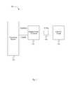
- FIG. 1is a block diagram illustrating a programmable input/output circuit environment according to an embodiment of the present invention.
- system 100includes processing system 110 , programmable input/output circuit 120 , I/O pad 130 and external circuit 140 .
- processing system 110may be the Programmable System on a Chip (PSoC®) processing device, manufactured by Cypress Semiconductor Corporation, San Jose, Calif.
- PSoC®Programmable System on a Chip
- processing system 110may be one or more other processing devices known by those of ordinary skill in the art, such as a microprocessor or central processing unit, a controller, special-purpose processor, digital signal processor (DSP), an application specific integrated circuit (ASIC), a field programmable gate array (FPGA), or the like.
- the processing system 110may be a network processor having multiple processors including a core unit and multiple microengines.
- the processing system 110may include any combination of general-purpose processing devices and special-purpose processing devices.
- programmable input/output circuit 120is external to processing system 110 . In other embodiments, however, programmable input/output circuit 120 may be included on the same chip as processing system 110 . Programmable input/output circuit 120 , along with I/O pad 130 , establish a link between processing system 110 and external circuit 140 . Programmable input/output circuit 120 moves signals CoreOut and CoreIn onto and off of processing system 110 . Details of the operation of programmable input/output circuit 120 will be provided below.
- the signals CoreOut and CoreInrepresent any output and input signals sent between processing system 110 and external circuit 140 . For example, signals the CoreOut and CoreIn may be generated by or directed to CPU core 1104 as shown in FIG. 11 .
- CoreOut and CoreInmay be sent to/from one or more other components in core architecture 1100 such as DMA controller 1120 , programmable digital block 1132 , programmable analog block 1134 , or other component either shown or not shown.
- the signals CoreOut or CoreInmay include multiple signals from multiple sources which are time multiplexed and provided over one or more common buses. Connections between programmable input/output circuit 120 and external circuit 140 may be made through I/O pad 130 .
- External circuit 140is representative of any circuit external to processing system 110 that may communicate with processing system 110 . In certain embodiments, external circuit 140 may be a subsystem embodied on the same integrated circuit as processing system 110 .
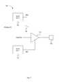
- FIG. 2is a circuit diagram illustrating a programmable input/output circuit according to an embodiment of the present invention.
- Programmable input/output circuit 200passes input and output signals CoreIn and CoreOut between processing system 110 as shown in FIGS. 1 , and I/O pad 230 .
- the signal CoreOutis received by programmable input/output circuit 200 at output buffer 210 .
- Output buffer 210may be a single input digital buffer with an adjustable signal Vref 1 .
- Output buffer 210functions as a tri-state output driver.
- Vref 1may be a reference voltage generated by processing system 110 and may be adjustable over a range of voltages, allowing the output high level of output buffer 210 to be programmed to a plurality of selectable voltage levels.
- output buffer 210When output buffer 210 is not enabled, output buffer 210 has an output in a high impedance state. The high impedance effectively removes output buffer 210 , and output signal CoreOut, from the circuit, allowing CoreOut and CoreIn to share the same I/O pad 230 .
- An input signalmay be received by programmable input/output circuit 200 through I/O pad 230 from an external circuit, such as external circuit 140 of FIG. 1 .
- the input signalis applied to an input of input comparator 220 .
- input comparator 220may be an operational amplifier operating in an open loop configuration.
- the received input signalmay be applied to a non-inverting input of the operational amplifier, while a second reference voltage Vref 2 is applied to the inverting input.
- the received input signalmay be applied to the inverting input while the second reference voltage Vref 2 is applied to the non-inverting input.
- the high gain of the operational amplifiercauses input comparator 220 to output the highest voltage it can if the voltage level of the signal at the non-inverting input is greater than that of the inverting input.
- the voltage of the input signal received at I/O pad 230is greater than the reference voltage Vref 2 , CoreIn will be passed as a high logic level from the output of input comparator 220 and applied to processing system 110 , as shown in FIG. 1 . If the voltage at pad 230 is less than Vref 2 , CoreIn will be passed as a low logic level.
- Vref 1 and Vref 2may be received from a number of places, depending on the embodiment.
- Vref 1 and Vref 2are generated by processing system 110 .
- Vref 1 and Vref 2may be supplied by an external circuit, such as external circuit 140 of FIG. 1 via I/O pad 130 .
- Vref 1 and Vref 2may be generated by different circuits, such as circuit 240 .
- Vref 1 and Vref 2may be user-selectable reference voltages. The values of Vref 1 and Vref 2 may be set in response to user-input received by processing system 110 .
- Vref 1 and Vref 2may be set, for example, by inputting or selecting a value from a register.
- Vref 2may have a value of approximately one half of the expected signal voltage range at I/O pad 230 .
- Van input signal has an expected voltage swing of 1 volt (V) (i.e., from 0 V to 1 V)
- Vref 2may have a voltage level of 0.5 V.
- the voltage level of the input signal at I/O pad 230is greater than halfway between 0 V and the expected 1 V (i.e., 0.5 V)
- CoreOutwill have a high logic output value.
- Vref 2may be programmable, however, so that the input threshold can be selected from any number of voltage levels in other embodiments.
- FIG. 3is a circuit diagram illustrating a programmable input/output circuit according to an embodiment of the present invention.
- Programmable input/output circuit 300passes input and output signals CoreIn and CoreOut between processing system 110 as shown in FIGS. 1 , and I/O pad 230 .
- the signal CoreOutis received by programmable input/output circuit 300 at output buffer 210 .
- Output buffer 210may be a single input digital buffer with an enable signal (not shown) and an adjustable signal Vref 1 , as discussed above with respect to FIG. 2 .
- An input signalmay be received by programmable input/output circuit 300 through I/O pad 230 from an external circuit, such as external circuit 140 of FIG. 1 .
- the input signalis applied to a non-inverting input of input comparator 220 .
- input comparator 220may be an operational amplifier operating in an open loop configuration, as discussed above with respect to FIG. 2 .
- the signal applied to an inverting input of input comparator 220may be selected from among a plurality of reference voltages Vrefa-Vrefn.
- One reference voltagemay be selected from the plurality of reference voltages to be applied to input comparator 220 using a selection circuit 340 .
- selection circuit 340may be a multiplexer. Multiplexer 340 may receive reference voltages Vrefa-Vrefn as inputs and output the selected reference voltage to the inverting input of input comparator 220 .
- reference voltages Vrefa-Vrefnare received from processing system 110 , however in other embodiments, the reference voltages may be received from some other circuit.
- the plurality of reference voltages available to multiplexer 340allow input/output circuit 300 to dynamically switch from a first reference voltage to a second reference voltage should the need arise.
- multiple external circuitsmay supply input signals of varying voltage levels to I/O pad 230 .
- input/output circuit 300may dynamically switch the reference voltages accordingly without interrupting operation of the system.
- selection signal Se 1is received from processing system 110 .
- Selection signal Se 1may be generated within processing system 110 by a CPU, by a direct memory access (DMA) transfer into a register, by a programmable or fixed function digital circuit, or by some other signal generation means.
- selection signal Se 1is received from an external circuit, such as external circuit 140 .
- the signal CoreInwill be passed as a high logic level from the input comparator 220 to processing system 110 , as shown in FIG. 1 . If the voltage level at pad 230 is less than the selected reference voltage, CoreIn will be passed as a low logic level.
- FIG. 4is a circuit diagram illustrating a programmable input/output circuit according to an embodiment according to an embodiment.
- Programmable input/output circuit 400passes input and output signals CoreIn and CoreOut between processing system 110 as shown in FIG. 1 , and I/O pad 230 .
- the signal CoreOutis received by programmable input/output circuit 400 at output buffer 210 .
- Output buffer 210may be a single input digital buffer with an enable signal (not shown) and an adjustable signal Vref 1 , as discussed above with respect to FIG. 2 .
- An input signalmay be received by programmable input/output circuit 400 through I/O pad 230 from an external circuit, such as external circuit 140 of FIG. 1 .
- the input signalis applied to a non-inverting input of input comparator 220 .
- input comparator 220may be an operational amplifier operating in an open loop configuration, as discussed above with respect to FIG. 2 .
- the input signal received at I/O pad 230may be compared to a reference voltage by input comparator 220 .
- the reference voltagemay be a fixed reference voltage Vref 2 , as shown in FIG. 2 .
- the reference voltagemay be selected from a plurality of reference voltages Vrefa-Vrefn by a selection circuit 340 as discussed above with respect to FIG. 3 .
- programmable input/output circuit 400also includes input buffer 425 .
- Input buffer 425may be a single input digital buffer which receives the input signal from I/O pad 230 .
- the signal CoreInmay be selected from either the output of input buffer 425 or the output of input comparator 220 .
- a selection circuit 450is used to select the signal for CoreIn.
- Selection circuit 450may be a multiplexer controlled by selection signal Se 1 _in, and configured to receive the outputs of input buffer 425 and input comparator 220 as inputs. Depending on the state of selection signal Se 1 _in, one of these signals is selected to be output as CoreIn and applied to processing system 110 .
- selection signal Se 1 _inis received from the same circuit as the selection signal Se 1 applied to multiplexer 340 . In other embodiments, however, selection signal Se 1 _in may be received from some other logic circuit. For example, Se 1 _in may be controlled by a user or by the connected external circuitry. The user may use selection signal Se 1 _in to decide between using the adjustable precision offered by input comparator 220 and the potential power savings of input buffer 425 depending on the particular application or connected circuit.
- FIG. 5is a circuit diagram illustrating a programmable input/output circuit according to an embodiment of the present invention.
- Programmable input/output circuit 500passes input and output signals CoreIn and CoreOut between processing system 110 as shown in FIGS. 1 , and I/O pad 230 .
- programmable input/output circuit 500includes output buffer 210 , input buffer 425 and input comparator 220 , as discussed above with respect to FIG. 4 .
- Programmable input/output circuit 500may also include reference generator circuit 560 .
- reference generator circuit 560provides reference voltage Vref 1 as the enable signal for output buffer 210 as well as one or more reference voltages Vrefb, Vrefc as inputs to multiplexer 340 .
- Reference generator circuit 560may receive a base reference voltage Vref from an external circuit 140 via I/O pad 130 , and through a circuit, such as for example a resistor divider, generate the additional reference voltages Vref 1 , Vrefb, Vrefc.
- Vrefbmay be one half the value of Vref 1 and Vrefc may be one half the value of Vrefb. In other embodiments, there may be some other relationship between the reference voltages.
- FIG. 6is a circuit diagram illustrating a programmable input/output circuit according to an embodiment of the present invention.
- Programmable input/output circuit 600passes input and output signals CoreIn and CoreOut between processing system 110 as shown in FIGS. 1 , and I/O pad 230 .
- the signal CoreOutis received by programmable input/output circuit 600 at output buffers 610 and 620 .
- Output buffers 610 and 620may be single input digital buffers controlled by output enable signal OE.
- output buffer 620is powered by supply voltage Vdd and output buffer 610 is powered by supply voltage Vcore.
- the supply voltagesmay be received from processing system 110 , where Vdd is, for example, the main supply voltage and Vcore is an internally regulated supply voltage.
- Output enable signal OEmay be a digital signal received from processing system 110 , which alternately enables output buffers 610 and 620 .
- output enable signal OEmay be directly applied to the first output buffer 610 as enable signal OE 1 , while OE is inverted before being applied to the second output buffer 620 as OE 2 .
- Output enable signal OEmay be inverted by inverter 622 . This allows output buffer 610 to be enabled while output buffer 620 is disabled, and output buffer 610 to be disabled while output buffer 620 is enabled.
- output enable signalmay be applied directly to output buffer 620 and inverted before being applied to input buffer 610 .
- the output enable signal OEmay be disabled causing neither output buffer 610 nor output buffer 620 to be enabled. When neither output buffer is enabled, both output buffers 610 and 620 may have an output in a high impedance state.
- output signal CoreOutis applied to level shifting circuit 625 before it reaches output buffer 620 .
- CoreOutmay be at the approximate voltage level of the core Vcore of processing system 110 .
- level shifting circuit 625shifts the voltage level of CoreOut from Vcore to Vdd.
- Vddmay be approximately 5 V and Vcore may be approximately 1.8 V, however, in other embodiments, the supply voltages may have other values.
- CoreOutmay be applied to a level shifting circuit before it reaches output buffer 610 , or may be applied to a level shifting circuit before it reaches both output buffer 610 and output buffer 620 .
- Level shifters, such as level shifting circuit 625are well known in the art and accordingly are not described here so as not to obscure the present invention.
- An input signalmay be received by programmable input/output circuit 600 through I/O pad 230 from an external circuit, such as external circuit 140 of FIG. 1 .
- the input signalis applied to input buffer 640 .
- Input buffer 640may be a single input digital buffer which receives the input signal from I/O pad 230 .
- Input buffer 640may have an enable signal IE that is selected from a number of voltages, such as Vdd and Vcore. Enable signal IE may be alternately switched between Vcore and Vdd by switches 642 and 644 . Switches 642 and 644 may be controlled by select signal Se 1 .
- select signal Se 1input buffer 640 may be programmed according to the voltage level of the input signal received at I/O pad 230 .
- input/output circuit 600may include input comparator 220 and/or input buffer 425 as shown in FIG. 2 , 3 , 4 or 5 .
- input/output circuit 600may include output buffer 210 as shown in FIG. 2 , 3 , 4 or 5 .
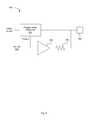
- FIG. 7is a circuit diagram illustrating a programmable input/output circuit according to an embodiment of the present invention.
- Programmable input/output circuit 700passes input and output signals Analog I/O and CoreOut between processing system 110 as shown in FIGS. 1 , and I/O pad 230 .
- the signal CoreOutis received by programmable input/output circuit 700 at output buffer 710 .
- Output buffer 710may be a single input digital buffer with an enable signal OE 1 .
- Output buffer 710functions as a switch, such that when the enable signal OE 1 is applied to output buffer 710 , the logic level of the signal CoreOut is passed through output buffer 710 to pad 230 .
- enable signal OE 1may be generated by bidirectional generator 715 .
- An analog I/O signalmay be coupled between I/O pad 230 and processing system 110 through switch 720 .
- switch 720is controlled by enable signal OE 2 , which may be generated by bidirectional generator 725 .
- OE 1 and OE 2may be generated by the same signal generator and may be inverse of each other in order to alternately drive the I/O pad 230 with CoreOut through output buffer 710 and apply the analog voltage signal at I/O pad 230 to processing system 110 or other circuitry as Analog I/O.
- OE 1 and OE 2may be adjusted to be overlapping or non-overlapping as needed for proper functionality.
- one or both of OE 1 and OE 2may be generated by the CPU of processing device 110 , a DMA transfer to a register, by a programmable or fixed function digital circuit, or by some other signal generation means.
- FIG. 8is a circuit diagram illustrating a programmable input/output circuit according to an embodiment of the present invention.
- Programmable input/output circuit 800passes input and output signals Analog I/O and CoreOut between processing system 110 as shown in FIGS. 1 , and I/O pads 830 A- 830 N.
- programmable input/output circuit 800includes a number of circuits similar to programmable input/output circuit 700 of FIG. 7 .
- enable signals OE 1 A-OE 1 Nare disabled, causing output buffers 810 A- 810 N to be in a high impedance state.
- Enable signals OE 2 A-OE 2 Nmay be successively applied to switches in the Analog I/O line to measure the voltages at I/O Pads 830 A- 830 N.
- each of enable signals OE 2 A-OE 2 Nmay be generated by bi-directional generators 2 A 2 N.
- the Analog I/O lines coupled to each I/O pad 830 A- 830 Nmay be connected to a common internal analog net 860 .
- the analog net 860may route to a function such as analog-to-digital converter (ADC) 865 , or other fixed function or programmable analog circuit, for signal processing of the I/O pad voltages without direct interaction with a central processing unit (CPU) of processing system 110 .
- ADCanalog-to-digital converter
- CPUcentral processing unit
- a subset of all I/O pad voltages in circuit 800are measured.
- Analog net 860may be for example, a single wire, or may include one or more multiplexers having a complex hierarchy.
- FIG. 9is a circuit diagram illustrating a programmable reset polarity circuit according to an embodiment of the present invention.
- Programmable reset polarity circuit 900may include programmable external reset (XRES) cell 910 to optionally provide either positive or negative polarity for a reset signal received at I/O pad 930 .
- XRESprogrammable external reset
- the desired state of the reset polarityi.e., either positive or negative
- non-volatile memory element 920such as a non-volatile latch (NVL) bit or a fuse.
- Programmable XRES cell 910may include an input buffer that receives the logic level of the reset signal at I/O pad 930 and returns a high XRES signal to the device core when the reset signal is above or below the reset threshold, depending on the chosen polarity.
- the received Polarity signal from NVL bit 920causes programmable XRES cell 910 to invert the output if necessary for the chosen polarity. For example for positive polarity, programmable XRES cell 910 may output a logic high XRES signal when the received reset signal is high and may output a logic low XRES signal when the received reset signal is low.
- programmable XRES cell 910may output a logic high XRES signal when the received reset signal is low and may output a logic low XRES signal when the received reset signal is high.
- the Polarity signalmay adjust the threshold for detecting a reset signal.
- the thresholdmay be set at one-third of the voltage supply, while for negative polarity, the threshold may be set at two-thirds of the voltage supply. In other embodiments, the threshold may be set at any other value.
- buffer 940 and resistor 950may be used to drive I/O pad 930 to a voltage that does not assert the XRES signal. This may help to prevent causing an unwanted reset signal in an environment where electronic noise is prevalent.
- buffer 940may drive a low signal to I/O pad 930 to prevent a reset.
- I/O pad 930may be driven with a stronger signal than resistor 950 in order to assert a reset on the XRES signal.
- FIG. 10is a circuit diagram illustrating a programmable reset polarity circuit according to an embodiment of the present invention.
- Programmable reset polarity circuit 1000may be similar to circuit 900 shown in FIG. 9 .
- circuit 900because the NVL bit may be undefined or unknown when the device is first tested, there may be a delay or a low yield if the device has the unexpected polarity.
- Programmable reset polarity circuit 1000prevents this by making the control field somewhat larger, such as by using a bit 920 for the reset polarity state and several other bits as a key 1060 .
- the polarity bit statecan be considered, otherwise it is ignored and the device is configured with the default reset polarity.
- NVL key 1060includes 7 bits which is applied to AND gate 1070 along with NVL bit 920 to define the reset polarity signal Polarity.
- FIG. 11illustrates an embodiment of a core architecture 1100 of the Programmable System-on-Chip (PSoC®), such as that used in the PSoC3 family of products offered by Cypress Semiconductor Corporation (San Jose, Calif.).
- the core architecture 1100may represent processing system 110 as discussed above.
- the core architecture 1100includes a microcontroller 1102 .
- the microcontroller 1102includes a CPU (central processing unit) core 1104 , flash program storage 1106 , DOC (debug on chip) 1108 , a prefetch buffer 1110 , a private SRAM (static random access memory) 1112 , and special functions registers 1114 .
- the DOC 1108 , prefetch buffer 1110 , private SRAM 1112 , and special function registers 1114are coupled to the CPU core 1104
- the flash program storage 1106is coupled to the prefetch buffer 1110 .
- the core architecture 1100may also include a CHub (core hub) 1116 , including a bridge 1118 and a DMA (direct memory access) controller 1120 , that is coupled to the microcontroller 1102 via bus 1122 .
- the CHub 1116may provide the primary data and control interface between the microcontroller 1102 and its peripherals and memory, and a programmable core 1124 .
- the DMA controller 1120may be programmed to transfer data between system elements without burdening the CPU core 1104 . In various embodiments, each of these subcomponents of the microcontroller 1102 and CHub 1116 may be different with each choice or type of CPU core 1104 .
- the Chub 1116may also be coupled to shared SRAM 1126 and an SPC (system performance controller) 1128 .
- the private SRAM 1112is independent of the shared SRAM 1126 that is accessed by the microcontroller 1102 through the bridge 1118 .
- the CPU core 1104accesses the private SRAM 1112 without going through the bridge 1118 , thus allowing local register and RAM accesses to occur simultaneously with DMA access to shared SRAM 1126 .
- SRAMstatic random access memory
- these memory modulesmay be any suitable type of a wide variety of (volatile or non-volatile) memory or data storage modules in various other embodiments.
- the programmable core 1124may include various combinations of subcomponents (not shown), including, but not limited to, a digital logic array, digital peripherals, analog processing channels, global routing analog peripherals, DMA controller(s), SRAM and other appropriate types of data storage, TO ports, and other suitable types of subcomponents.
- the programmable core 1124includes a GPIO (general purpose IO) and EMIF (extended memory interface) block 1130 to provide a mechanism to extend the external off-chip access of the microcontroller 1102 , a programmable digital block 1132 , a programmable analog block 1134 , and a special functions block 1136 , each configured to implement one or more of the subcomponent functions.
- the special functions block 1136may include dedicated (non-programmable) functional blocks and/or include one or more interfaces to dedicated functional blocks, such as USB, a crystal oscillator drive, JTAG, and the like.
- the programmable digital block 1132may include a digital logic array including an array of digital logic blocks and associated routing.
- the digital block architectureis comprised of UDBs (universal digital blocks).
- each UDBmay include an ALU together with CPLD functionality.
- one or more UDBs of the programmable digital block 1132may be configured to perform various digital functions, including, but not limited to, one or more of the following functions: a basic 12C slave; an 12C master; a SPI master or slave; a multi-wire (e.g., 3-wire) SPI master or slave (e.g., MISO/MOSI multiplexed on a single pin); timers and counters (e.g., a pair of 8-bit timers or counters, one 16 bit timer or counter, one 8-bit capture timer, or the like); PWMs (e.g., a pair of 8-bit PWMs, one 16-bit PWM, one 8-bit deadband PWM, or the like), a level sensitive I/O interrupt generator; a quadrature encoder, a UART (e.g., half-duplex); delay lines; and any other suitable type of digital function or combination of digital functions which can be implemented in a plurality of UDBs.
- additional functionsmay be implemented using a group of two or more UDBs.
- the following functionscan be implemented using multiple UDBs: an 12C slave that supports hardware address detection and the ability to handle a complete transaction without CPU core (e.g., CPU core 1104 ) intervention and to help prevent the force clock stretching on any bit in the data stream; an 12C multi-master which may include a slave option in a single block; an arbitrary length PRS or CRC (up to 32 bits); SDIO; SGPIO; a digital correlator (e.g., having up to 32 bits with 4 ⁇ over-sampling and supporting a configurable threshold); a LINbus interface; a delta-sigma modulator (e.g., for class D audio DAC having a differential output pair); an 12S (stereo); an LCD drive control (e.g., UDBs may be used to implement timing control of the LCD drive blocks and provide display RAM addressing); full-duplex UART (e.g.,
- the programmable analog block 1134may include analog resources including, but not limited to, comparators, mixers, PGAs (programmable gain amplifiers), TIAs (trans-impedance amplifiers), ADCs (analog-to-digital converters), DACs (digitalto-analog converters), voltage references, current sources, sample and hold circuits, and any other suitable type of analog resources.
- analog resourcesincluding, but not limited to, comparators, mixers, PGAs (programmable gain amplifiers), TIAs (trans-impedance amplifiers), ADCs (analog-to-digital converters), DACs (digitalto-analog converters), voltage references, current sources, sample and hold circuits, and any other suitable type of analog resources.
- the programmable analog block 1134may support various analog functions including, but not limited to, analog routing, LCD drive TO support, capacitive sensing, voltage measurement, motor control, current to voltage conversion, voltage to frequency conversion, differential amplification, light measurement, inductive position monitoring, filtering, voice coil driving, magnetic card reading, acoustic doppler measurement, echo-ranging, modem transmission and receive encoding, or any other suitable type of analog function.
- Embodiments of the present inventioninclude various operations described herein. These operations may be performed by hardware components, software, firmware, or a combination thereof. Any of the signals provided over various buses described herein may be time multiplexed with other signals and provided over one or more common buses. Additionally, the interconnection between circuit components or blocks may be shown as buses or as single signal lines. Each of the buses may alternatively be one or more single signal lines and each of the single signal lines may alternatively be buses.
- Certain embodimentsmay be implemented as a computer program product that may include instructions stored on a machine-readable medium. These instructions may be used to program a general-purpose or special-purpose processor to perform the described operations.
- a machine-readable mediumincludes any mechanism for storing or transmitting information in a form (e.g., software, processing application) readable by a machine (e.g., a computer).
- the machine-readable mediummay include, but is not limited to, magnetic storage medium (e.g., floppy diskette); optical storage medium (e.g., CD-ROM); magneto-optical storage medium; read-only memory (ROM); random-access memory (RAM); erasable programmable memory (e.g., EPROM and EEPROM); flash memory; or another type of medium suitable for storing electronic instructions.
- magnetic storage mediume.g., floppy diskette
- optical storage mediume.g., CD-ROM
- magneto-optical storage mediume.g., magneto-optical storage medium
- ROMread-only memory
- RAMrandom-access memory
- EPROM and EEPROMerasable programmable memory
- flash memoryor another type of medium suitable for storing electronic instructions.
- some embodimentsmay be practiced in distributed computing environments where the machine-readable medium is stored on and/or executed by more than one computer system.
- the information transferred between computer systemsmay either be pulled or pushed across the communication medium connecting the computer systems.
Landscapes
- Engineering & Computer Science (AREA)
- Theoretical Computer Science (AREA)
- Physics & Mathematics (AREA)
- General Engineering & Computer Science (AREA)
- Computer Hardware Design (AREA)
- General Physics & Mathematics (AREA)
- Computing Systems (AREA)
- Mathematical Physics (AREA)
- Logic Circuits (AREA)
Abstract
Description
Claims (20)
Priority Applications (5)
| Application Number | Priority Date | Filing Date | Title |
|---|---|---|---|
| US14/054,657US9013209B1 (en) | 2009-05-05 | 2013-10-15 | Programmable input/output circuit |
| US14/690,106US9515659B2 (en) | 2009-05-05 | 2015-04-17 | Programmable input/output circuit |
| US15/369,674US10153770B2 (en) | 2009-05-05 | 2016-12-05 | Programmable input/output circuit |
| US16/193,261US10666258B2 (en) | 2009-05-05 | 2018-11-16 | Programmable input/output circuit |
| US16/862,043US11088692B2 (en) | 2009-05-05 | 2020-04-29 | Programmable input/output circuit |
Applications Claiming Priority (6)
| Application Number | Priority Date | Filing Date | Title |
|---|---|---|---|
| US17558609P | 2009-05-05 | 2009-05-05 | |
| US17585609P | 2009-05-06 | 2009-05-06 | |
| US17693309P | 2009-05-10 | 2009-05-10 | |
| US12/753,657US8179161B1 (en) | 2009-05-05 | 2010-04-02 | Programmable input/output circuit |
| US13/427,264US8558578B1 (en) | 2009-05-05 | 2012-03-22 | Programmable input/output circuit |
| US14/054,657US9013209B1 (en) | 2009-05-05 | 2013-10-15 | Programmable input/output circuit |
Related Parent Applications (1)
| Application Number | Title | Priority Date | Filing Date |
|---|---|---|---|
| US13/427,264ContinuationUS8558578B1 (en) | 2009-05-05 | 2012-03-22 | Programmable input/output circuit |
Related Child Applications (1)
| Application Number | Title | Priority Date | Filing Date |
|---|---|---|---|
| US14/690,106ContinuationUS9515659B2 (en) | 2009-05-05 | 2015-04-17 | Programmable input/output circuit |
Publications (1)
| Publication Number | Publication Date |
|---|---|
| US9013209B1true US9013209B1 (en) | 2015-04-21 |
Family
ID=46033212
Family Applications (7)
| Application Number | Title | Priority Date | Filing Date |
|---|---|---|---|
| US12/753,657ActiveUS8179161B1 (en) | 2009-05-05 | 2010-04-02 | Programmable input/output circuit |
| US13/427,264ActiveUS8558578B1 (en) | 2009-05-05 | 2012-03-22 | Programmable input/output circuit |
| US14/054,657ActiveUS9013209B1 (en) | 2009-05-05 | 2013-10-15 | Programmable input/output circuit |
| US14/690,106ActiveUS9515659B2 (en) | 2009-05-05 | 2015-04-17 | Programmable input/output circuit |
| US15/369,674ActiveUS10153770B2 (en) | 2009-05-05 | 2016-12-05 | Programmable input/output circuit |
| US16/193,261ActiveUS10666258B2 (en) | 2009-05-05 | 2018-11-16 | Programmable input/output circuit |
| US16/862,043ActiveUS11088692B2 (en) | 2009-05-05 | 2020-04-29 | Programmable input/output circuit |
Family Applications Before (2)
| Application Number | Title | Priority Date | Filing Date |
|---|---|---|---|
| US12/753,657ActiveUS8179161B1 (en) | 2009-05-05 | 2010-04-02 | Programmable input/output circuit |
| US13/427,264ActiveUS8558578B1 (en) | 2009-05-05 | 2012-03-22 | Programmable input/output circuit |
Family Applications After (4)
| Application Number | Title | Priority Date | Filing Date |
|---|---|---|---|
| US14/690,106ActiveUS9515659B2 (en) | 2009-05-05 | 2015-04-17 | Programmable input/output circuit |
| US15/369,674ActiveUS10153770B2 (en) | 2009-05-05 | 2016-12-05 | Programmable input/output circuit |
| US16/193,261ActiveUS10666258B2 (en) | 2009-05-05 | 2018-11-16 | Programmable input/output circuit |
| US16/862,043ActiveUS11088692B2 (en) | 2009-05-05 | 2020-04-29 | Programmable input/output circuit |
Country Status (1)
| Country | Link |
|---|---|
| US (7) | US8179161B1 (en) |
Families Citing this family (28)
| Publication number | Priority date | Publication date | Assignee | Title |
|---|---|---|---|---|
| US8176296B2 (en) | 2000-10-26 | 2012-05-08 | Cypress Semiconductor Corporation | Programmable microcontroller architecture |
| US6724220B1 (en) | 2000-10-26 | 2004-04-20 | Cyress Semiconductor Corporation | Programmable microcontroller architecture (mixed analog/digital) |
| US8441298B1 (en) | 2008-07-01 | 2013-05-14 | Cypress Semiconductor Corporation | Analog bus sharing using transmission gates |
| JP2010252090A (en)* | 2009-04-16 | 2010-11-04 | Rohm Co Ltd | Semiconductor device |
| US8135884B1 (en) | 2009-05-04 | 2012-03-13 | Cypress Semiconductor Corporation | Programmable interrupt routing system |
| US8179161B1 (en) | 2009-05-05 | 2012-05-15 | Cypress Semiconductor Corporation | Programmable input/output circuit |
| US8487655B1 (en) | 2009-05-05 | 2013-07-16 | Cypress Semiconductor Corporation | Combined analog architecture and functionality in a mixed-signal array |
| US9612987B2 (en) | 2009-05-09 | 2017-04-04 | Cypress Semiconductor Corporation | Dynamically reconfigurable analog routing circuits and methods for system on a chip |
| MX2012003203A (en)* | 2010-07-02 | 2012-05-08 | Schweitzer Engineering Lab Inc | Systems and methods for remote device management. |
| CN102798582A (en)* | 2012-05-22 | 2012-11-28 | 山东理工大学 | Proportional photon correlator based on digital signal processor (DSP) annular buffer area |
| DE102014012660A1 (en)* | 2013-12-11 | 2015-06-11 | Diehl Aerospace Gmbh | Configurable interface circuit |
| WO2015148724A1 (en)* | 2014-03-26 | 2015-10-01 | Pqj Corp | System and method for communicating with and for controlling of programmable apparatuses |
| US9172379B1 (en)* | 2014-09-26 | 2015-10-27 | Altera Corporation | Efficient controllers and implementations for elastic buffers |
| WO2016075727A1 (en)* | 2014-11-14 | 2016-05-19 | ルネサスエレクトロニクス株式会社 | Semiconductor device and control method therefor |
| US10031877B2 (en)* | 2015-02-13 | 2018-07-24 | Invensense, Inc. | Including control data in a serial audio stream |
| KR20160146403A (en)* | 2015-06-12 | 2016-12-21 | 에스케이하이닉스 주식회사 | Impedance calibration circuit |
| GB2546232A (en) | 2015-06-16 | 2017-07-19 | Nordic Semiconductor Asa | Integrated circuit inputs and outputs |
| US9866055B2 (en)* | 2015-06-19 | 2018-01-09 | Cypress Semiconductor Corporation | Automatic scheme to detect multi-standard charger types |
| US9854654B2 (en) | 2016-02-03 | 2017-12-26 | Pqj Corp | System and method of control of a programmable lighting fixture with embedded memory |
| US10276726B2 (en)* | 2016-05-31 | 2019-04-30 | Taiwan Semiconductor Manufacturing Co., Ltd. | Non-volatile memory cell and non-volatile memory |
| US20180331623A1 (en)* | 2017-05-10 | 2018-11-15 | Infineon Technologies Ag | Input/output circuit |
| RU173173U1 (en)* | 2017-05-10 | 2017-08-15 | Федеральное государственное автономное образовательное учреждение высшего образования "Санкт-Петербургский государственный университет аэрокосмического приборостроения" | PARALLEL REPEATER |
| TWI665562B (en)* | 2017-11-29 | 2019-07-11 | 英業達股份有限公司 | Control system and control method thereof |
| CN108923778A (en)* | 2018-06-22 | 2018-11-30 | 比飞力(深圳)科技有限公司 | A kind of logic level converting circuit and integrated circuit |
| US11165434B2 (en) | 2019-03-15 | 2021-11-02 | Analog Devices International Unlimited Company | Leakage reduction for multi-function configurable circuit |
| CN112799986B (en)* | 2019-11-13 | 2024-03-26 | 瑞昱半导体股份有限公司 | Universal serial bus switching circuit and related electronic device |
| US11474964B2 (en)* | 2020-10-28 | 2022-10-18 | Moxa Inc. | Configurable input/output device and operation method thereof |
| US12393257B2 (en)* | 2022-09-06 | 2025-08-19 | Apple Inc. | Wakeup circuit |
Citations (63)
| Publication number | Priority date | Publication date | Assignee | Title |
|---|---|---|---|---|
| US4771285A (en) | 1985-11-05 | 1988-09-13 | Advanced Micro Devices, Inc. | Programmable logic cell with flexible clocking and flexible feedback |
| US5412261A (en) | 1992-04-14 | 1995-05-02 | Aptix Corporation | Two-stage programmable interconnect architecture |
| US5424589A (en) | 1993-02-12 | 1995-06-13 | The Board Of Trustees Of The Leland Stanford Junior University | Electrically programmable inter-chip interconnect architecture |
| US5481471A (en) | 1992-12-18 | 1996-01-02 | Hughes Aircraft Company | Mixed signal integrated circuit architecture and test methodology |
| US5528172A (en) | 1994-12-27 | 1996-06-18 | Honeywell Inc. | Adjustable voltage level shifter |
| US5563526A (en) | 1994-01-03 | 1996-10-08 | Texas Instruments Incorporated | Programmable mixed-mode integrated circuit architecture |
| US5598408A (en) | 1990-01-05 | 1997-01-28 | Maspar Computer Corporation | Scalable processor to processor and processor to I/O interconnection network and method for parallel processing arrays |
| US5604450A (en)* | 1995-07-27 | 1997-02-18 | Intel Corporation | High speed bidirectional signaling scheme |
| US5625301A (en) | 1995-05-18 | 1997-04-29 | Actel Corporation | Flexible FPGA input/output architecture |
| US5635745A (en) | 1994-09-08 | 1997-06-03 | National Semiconductor Corporation | Analog multiplexer cell for mixed digital and analog signal inputs |
| US5671432A (en) | 1995-06-02 | 1997-09-23 | International Business Machines Corporation | Programmable array I/O-routing resource |
| US5748875A (en) | 1996-06-12 | 1998-05-05 | Simpod, Inc. | Digital logic simulation/emulation system |
| US5754826A (en) | 1995-08-04 | 1998-05-19 | Synopsys, Inc. | CAD and simulation system for targeting IC designs to multiple fabrication processes |
| EP0871223A1 (en) | 1996-10-10 | 1998-10-14 | Semiconductores Investigaci n Y Diseno S.A. -(SIDSA) | Process for the prototyping of mixed signal applications and field programmable system on a chip for applying said process |
| US5877633A (en)* | 1996-01-03 | 1999-03-02 | Motorola, Inc. | Bidirectional voltage translator |
| US5894565A (en) | 1996-05-20 | 1999-04-13 | Atmel Corporation | Field programmable gate array with distributed RAM and increased cell utilization |
| US5966047A (en) | 1997-03-27 | 1999-10-12 | Motorola, Inc. | Programmable analog array and method |
| US6072334A (en)* | 1998-07-16 | 2000-06-06 | Via Technologies, Inc. | Signal converter with a dynamically adjustable reference voltage and chipset including the same |
| US6188381B1 (en) | 1997-09-08 | 2001-02-13 | Sarnoff Corporation | Modular parallel-pipelined vision system for real-time video processing |
| US6246259B1 (en) | 1998-02-23 | 2001-06-12 | Xilinx, Inc. | High-speed programmable logic architecture having active CMOS device drivers |
| US6362649B1 (en) | 1997-01-31 | 2002-03-26 | Actel Corporation | Field programmable gate array with mask programmed input and output buffers |
| US6424175B1 (en)* | 2000-09-11 | 2002-07-23 | Intel Corporation | Biased control loop circuit for setting impedance of output driver |
| US20020118475A1 (en) | 2001-02-26 | 2002-08-29 | David Ng | System and method providing programmable GMR head pin layer reset in conjunction with high density drive read/write preamplifiers |
| US6453422B1 (en)* | 1999-12-23 | 2002-09-17 | Intel Corporation | Reference voltage distribution for multiload i/o systems |
| US20030067919A1 (en) | 2001-10-04 | 2003-04-10 | Chunming Qiao | Labeled analog burst switching for any high-layer-over-signal channel integration |
| US6583652B1 (en) | 2001-06-01 | 2003-06-24 | Lattice Semiconductor Corporation | Highly linear programmable transconductor with large input-signal range |
| US20030120977A1 (en) | 2001-07-30 | 2003-06-26 | Chih-Chien Tang | Debugging method through serial port under system shutdown and standby conditions |
| US6639426B2 (en)* | 2000-06-28 | 2003-10-28 | Intel Corporation | Apparatus for testing simultaneous bi-directional I/O circuits |
| US6717436B2 (en) | 1999-09-29 | 2004-04-06 | Infineon Technologies Ag | Reconfigurable gate array |
| US6724220B1 (en) | 2000-10-26 | 2004-04-20 | Cyress Semiconductor Corporation | Programmable microcontroller architecture (mixed analog/digital) |
| US6735706B2 (en) | 2000-12-06 | 2004-05-11 | Lattice Semiconductor Corporation | Programmable power management system and method |
| US6738415B2 (en)* | 2001-03-22 | 2004-05-18 | Sun Microsystems, Inc. | Bi-directional communication system |
| US20040113655A1 (en) | 2002-12-13 | 2004-06-17 | Xilinx, Inc. | Partial reconfiguration of a programmable logic device using an on-chip processor |
| US6762632B1 (en) | 2003-05-15 | 2004-07-13 | Stmicroelectronics, Inc. | Reset driver circuits and methods |
| US20040141392A1 (en) | 2003-01-13 | 2004-07-22 | Lee Yun-Woo | Input/output buffer having analog and digital input modes |
| US6791356B2 (en)* | 2001-06-28 | 2004-09-14 | Intel Corporation | Bidirectional port with clock channel used for synchronization |
| US20040184601A1 (en)* | 2002-12-31 | 2004-09-23 | Kim Woo-Seop | Simultaneous bidirectional input/output circuit and method |
| US6809572B2 (en) | 2002-09-18 | 2004-10-26 | Cirrus Logic, Incorporated | Integrated circuit with automatic polarity detection and configuration |
| US6833732B2 (en) | 2003-02-05 | 2004-12-21 | Winbond Electronics Corp. | Output signal circuit capable of automatically detecting polarity |
| US6895530B2 (en) | 2003-01-24 | 2005-05-17 | Freescale Semiconductor, Inc. | Method and apparatus for controlling a data processing system during debug |
| US6971004B1 (en) | 2001-11-19 | 2005-11-29 | Cypress Semiconductor Corp. | System and method of dynamically reconfiguring a programmable integrated circuit |
| US6981090B1 (en) | 2000-10-26 | 2005-12-27 | Cypress Semiconductor Corporation | Multiple use of microcontroller pad |
| US6996796B2 (en) | 2002-02-22 | 2006-02-07 | Xilinx, Inc. | Method and system for creating a customized support package for an FPGA-based system-on-chip (SoC) |
| US7023238B1 (en) | 2004-01-07 | 2006-04-04 | Altera Corporation | Input buffer with selectable threshold and hysteresis option |
| US7046035B2 (en) | 2001-04-18 | 2006-05-16 | Silicon Laboratories Cp, Inc. | Programmable driver for an I/O pin of an integrated circuit |
| EP1713252A1 (en) | 2004-01-22 | 2006-10-18 | Semiconductores Investigaci n Y Diseno S.A. -(SIDSA) | Integrated circuit for the processing and subsequent routing of motion picture expert group (mpeg) data between interfaces |
| US7133945B2 (en)* | 2004-09-15 | 2006-11-07 | Rambus Inc. | Scalable I/O signaling topology using source-calibrated reference voltages |
| US7173347B2 (en) | 2002-10-15 | 2007-02-06 | Denso Corporation | Method and apparatus for driving and controlling on-vehicle loads |
| US7266632B2 (en) | 2001-05-18 | 2007-09-04 | Xilinx, Inc. | Programmable logic device including programmable interface core and central processing unit |
| US20070214389A1 (en) | 2006-03-08 | 2007-09-13 | Severson Matthew L | JTAG power collapse debug |
| US7299307B1 (en) | 2002-12-24 | 2007-11-20 | Cypress Semiconductor Corporation | Analog I/O with digital signal processor array |
| US7308608B1 (en) | 2002-05-01 | 2007-12-11 | Cypress Semiconductor Corporation | Reconfigurable testing system and method |
| US7340693B2 (en) | 2005-02-24 | 2008-03-04 | Nick Martin | System for designing re-programmable digital hardware platforms |
| US7360005B2 (en) | 1999-10-22 | 2008-04-15 | Mou-Shiung Lin | Software programmable multiple function integrated circuit module |
| US7386740B2 (en) | 2000-10-30 | 2008-06-10 | Cypress Semiconductor Corporation | Method for efficient supply of power to a microcontroller |
| US7436207B2 (en) | 2006-07-21 | 2008-10-14 | Microchip Technology Incorporated | Integrated circuit device having at least one of a plurality of bond pads with a selectable plurality of input-output functionalities |
| US20080258760A1 (en) | 2007-04-17 | 2008-10-23 | Cypress Semiconductor Corporation | System level interconnect with programmable switching |
| US7603578B2 (en) | 2003-07-31 | 2009-10-13 | Actel Corporation | Programmable system on a chip for power-supply voltage and current monitoring and control |
| US7609178B2 (en) | 2006-04-20 | 2009-10-27 | Pressure Profile Systems, Inc. | Reconfigurable tactile sensor input device |
| US7737724B2 (en) | 2007-04-17 | 2010-06-15 | Cypress Semiconductor Corporation | Universal digital block interconnection and channel routing |
| US7755412B2 (en)* | 2008-04-01 | 2010-07-13 | Kyocera Corporation | Bi-directional level shifted interrupt control |
| US8179161B1 (en) | 2009-05-05 | 2012-05-15 | Cypress Semiconductor Corporation | Programmable input/output circuit |
| US8441298B1 (en) | 2008-07-01 | 2013-05-14 | Cypress Semiconductor Corporation | Analog bus sharing using transmission gates |
Family Cites Families (54)
| Publication number | Priority date | Publication date | Assignee | Title |
|---|---|---|---|---|
| US736005A (en) | 1903-03-26 | 1903-08-11 | William H Peak | Copy-holder. |
| JPS6010644A (en) | 1983-06-30 | 1985-01-19 | Toshiba Corp | Manufacturing method of semiconductor device |
| US5450596A (en) | 1991-07-18 | 1995-09-12 | Redwear Interactive Inc. | CD-ROM data retrieval system using a hands-free command controller and headwear monitor |
| US5634076A (en) | 1994-10-04 | 1997-05-27 | Analog Devices, Inc. | DMA controller responsive to transition of a request signal between first state and second state and maintaining of second state for controlling data transfer |
| US5835733A (en) | 1994-12-22 | 1998-11-10 | Texas Instruments Incorporated | Method and apparatus for implementing a single DMA controller to perform DMA operations for devices on multiple buses in docking stations, notebook and desktop computer system |
| US5998408A (en) | 1996-10-16 | 1999-12-07 | Merck & Co., Inc. | Triterpene derivatives with immunosuppressant activity |
| US5889480A (en) | 1996-10-18 | 1999-03-30 | Samsung Electronics Co., Ltd. | Full duplex serial codec interface with DMA |
| US6157426A (en) | 1998-02-13 | 2000-12-05 | Ois Optical Imaging Systems, Inc. | Liquid crystal display with SiOx Ny inclusive multilayer black matrix |
| US6311292B1 (en) | 1998-07-30 | 2001-10-30 | Sandcraft, Inc. | Circuit, architecture and method for analyzing the operation of a digital processing system |
| EP0982665A3 (en) | 1998-08-21 | 2004-02-04 | Matsushita Electronics Corporation | A bus system and a master device that stabilizes bus electric potential during non-access periods |
| US6461899B1 (en) | 1999-04-30 | 2002-10-08 | Semiconductor Energy Laboratory, Co., Ltd. | Oxynitride laminate “blocking layer” for thin film semiconductor devices |
| US6826717B1 (en) | 2000-06-12 | 2004-11-30 | Altera Corporation | Synchronization of hardware and software debuggers |
| US8176296B2 (en) | 2000-10-26 | 2012-05-08 | Cypress Semiconductor Corporation | Programmable microcontroller architecture |
| US6825689B1 (en)* | 2000-10-26 | 2004-11-30 | Cypress Semiconductor Corporation | Configurable input/output interface for a microcontroller |
| US7149316B1 (en)* | 2000-10-26 | 2006-12-12 | Cypress Semiconductor Corporation | Microcontroller having an on-chip high gain amplifier |
| US8283300B2 (en) | 2000-11-27 | 2012-10-09 | The Procter & Gamble Company | Detergent products, methods and manufacture |
| US6292409B1 (en)* | 2000-12-12 | 2001-09-18 | Lsi Logic Corporation | System for programmable chip initialization |
| US6445030B1 (en) | 2001-01-30 | 2002-09-03 | Advanced Micro Devices, Inc. | Flash memory erase speed by fluorine implant or fluorination |
| US6768856B2 (en) | 2001-02-09 | 2004-07-27 | Corning Incorporated | High germanium content waveguide materials |
| US6862642B1 (en) | 2001-05-15 | 2005-03-01 | Adaptec, Inc. | Expander device and method for resetting bus segments in I/O subsystem segmented with expanders |
| US7207041B2 (en) | 2001-06-28 | 2007-04-17 | Tranzeo Wireless Technologies, Inc. | Open platform architecture for shared resource access management |
| US6709928B1 (en) | 2001-07-31 | 2004-03-23 | Cypress Semiconductor Corporation | Semiconductor device having silicon-rich layer and method of manufacturing such a device |
| KR100437466B1 (en) | 2001-12-27 | 2004-06-23 | 삼성전자주식회사 | Non-volatile memory device and method of fabricating the same |
| US6986085B2 (en)* | 2002-03-08 | 2006-01-10 | Agilent Technologies, Inc. | Systems and methods for facilitating testing of pad drivers of integrated circuits |
| US7194559B2 (en)* | 2002-08-29 | 2007-03-20 | Intel Corporation | Slave I/O driver calibration using error-nulling master reference |
| US20040128590A1 (en) | 2002-12-30 | 2004-07-01 | Michael Derr | Patch mechanism |
| US6799227B2 (en) | 2003-01-06 | 2004-09-28 | Lsi Logic Corporation | Dynamic configuration of a time division multiplexing port and associated direct memory access controller |
| US6816922B2 (en) | 2003-04-14 | 2004-11-09 | Faraday Technology Corp. | Digital signal processor with a byte DMA controller |
| US7146285B2 (en) | 2003-05-19 | 2006-12-05 | Avago Technologies General Ip (Singapore) Pte. Ltd. | Integrated circuit with parameter measurement |
| US7366652B2 (en) | 2003-06-16 | 2008-04-29 | Springsoft, Inc. | Method of programming a co-verification system |
| JP3807406B2 (en) | 2003-09-05 | 2006-08-09 | セイコーエプソン株式会社 | Data transfer control device and electronic device |
| US6958511B1 (en) | 2003-10-06 | 2005-10-25 | Fasl, Llc | Flash memory device and method of fabrication thereof including a bottom oxide layer with two regions with different concentrations of nitrogen |
| US7213172B2 (en) | 2004-03-31 | 2007-05-01 | Intel Corporation | Debugging power management |
| US7802023B2 (en) | 2004-10-15 | 2010-09-21 | Sony Computer Entertainment Inc. | Methods and apparatus for supporting multiple configurations in a multi-processor system |
| US7584456B1 (en) | 2005-01-14 | 2009-09-01 | Altera Corporation | Method and apparatus for debugging embedded systems having read only memory |
| US7417459B2 (en) | 2005-04-06 | 2008-08-26 | Intel Corporation | On-die offset reference circuit block |
| US7612403B2 (en) | 2005-05-17 | 2009-11-03 | Micron Technology, Inc. | Low power non-volatile memory and gate stack |
| US7665002B1 (en) | 2005-12-14 | 2010-02-16 | Advanced Micro Devices, Inc. | Multi-core integrated circuit with shared debug port |
| US7814166B2 (en) | 2006-01-27 | 2010-10-12 | Sony Computer Entertainment Inc. | Methods and apparatus for virtualizing an address space |
| US7886112B2 (en) | 2006-05-24 | 2011-02-08 | Sony Computer Entertainment Inc. | Methods and apparatus for providing simultaneous software/hardware cache fill |
| US8327158B2 (en) | 2006-11-01 | 2012-12-04 | Texas Instruments Incorporated | Hardware voting mechanism for arbitrating scaling of shared voltage domain, integrated circuits, processes and systems |
| US7583104B2 (en)* | 2006-12-12 | 2009-09-01 | Microchip Technology Incorporated | Maintaining input and/or output configuration and data state during and when coming out of a low power mode |
| US7450423B2 (en) | 2007-01-03 | 2008-11-11 | Macronix International Co., Ltd. | Methods of operating non-volatile memory cells having an oxide/nitride multilayer insulating structure |
| US8316158B1 (en) | 2007-03-12 | 2012-11-20 | Cypress Semiconductor Corporation | Configuration of programmable device using a DMA controller |
| US8779495B2 (en) | 2007-04-19 | 2014-07-15 | Qimonda Ag | Stacked SONOS memory |
| US8001390B2 (en) | 2007-05-09 | 2011-08-16 | Sony Computer Entertainment Inc. | Methods and apparatus for secure programming and storage of data using a multiprocessor in a trusted mode |
| US20080307240A1 (en) | 2007-06-08 | 2008-12-11 | Texas Instruments Incorporated | Power management electronic circuits, systems, and methods and processes of manufacture |
| US8030959B2 (en) | 2008-06-12 | 2011-10-04 | Texas Instruments Incorporated | Device-under-test power management |
| US7808277B2 (en)* | 2008-09-18 | 2010-10-05 | Hewlett-Packard Development Company, L.P. | Bidirectional signal separation module for a bus converter |
| US7973556B1 (en) | 2009-03-05 | 2011-07-05 | Xilinx, Inc. | System and method for using reconfiguration ports for power management in integrated circuits |
| US8487655B1 (en) | 2009-05-05 | 2013-07-16 | Cypress Semiconductor Corporation | Combined analog architecture and functionality in a mixed-signal array |
| US8601315B2 (en) | 2010-11-01 | 2013-12-03 | Freescale Semiconductor, Inc. | Debugger recovery on exit from low power mode |
| US9170971B2 (en) | 2012-12-26 | 2015-10-27 | Iii Holdings 2, Llc | Fabric discovery for a cluster of nodes |
| US9784791B2 (en) | 2014-07-18 | 2017-10-10 | Intel Corporation | Apparatus and method to debug a voltage regulator |
- 2010
- 2010-04-02USUS12/753,657patent/US8179161B1/enactiveActive
- 2012
- 2012-03-22USUS13/427,264patent/US8558578B1/enactiveActive
- 2013
- 2013-10-15USUS14/054,657patent/US9013209B1/enactiveActive
- 2015
- 2015-04-17USUS14/690,106patent/US9515659B2/enactiveActive
- 2016
- 2016-12-05USUS15/369,674patent/US10153770B2/enactiveActive
- 2018
- 2018-11-16USUS16/193,261patent/US10666258B2/enactiveActive
- 2020
- 2020-04-29USUS16/862,043patent/US11088692B2/enactiveActive
Patent Citations (70)
| Publication number | Priority date | Publication date | Assignee | Title |
|---|---|---|---|---|
| US4771285A (en) | 1985-11-05 | 1988-09-13 | Advanced Micro Devices, Inc. | Programmable logic cell with flexible clocking and flexible feedback |
| US5598408A (en) | 1990-01-05 | 1997-01-28 | Maspar Computer Corporation | Scalable processor to processor and processor to I/O interconnection network and method for parallel processing arrays |
| US5412261A (en) | 1992-04-14 | 1995-05-02 | Aptix Corporation | Two-stage programmable interconnect architecture |
| US5481471A (en) | 1992-12-18 | 1996-01-02 | Hughes Aircraft Company | Mixed signal integrated circuit architecture and test methodology |
| US5424589A (en) | 1993-02-12 | 1995-06-13 | The Board Of Trustees Of The Leland Stanford Junior University | Electrically programmable inter-chip interconnect architecture |
| US5563526A (en) | 1994-01-03 | 1996-10-08 | Texas Instruments Incorporated | Programmable mixed-mode integrated circuit architecture |
| US5635745A (en) | 1994-09-08 | 1997-06-03 | National Semiconductor Corporation | Analog multiplexer cell for mixed digital and analog signal inputs |
| US5528172A (en) | 1994-12-27 | 1996-06-18 | Honeywell Inc. | Adjustable voltage level shifter |
| US5625301A (en) | 1995-05-18 | 1997-04-29 | Actel Corporation | Flexible FPGA input/output architecture |
| US5671432A (en) | 1995-06-02 | 1997-09-23 | International Business Machines Corporation | Programmable array I/O-routing resource |
| US5604450A (en)* | 1995-07-27 | 1997-02-18 | Intel Corporation | High speed bidirectional signaling scheme |
| US5754826A (en) | 1995-08-04 | 1998-05-19 | Synopsys, Inc. | CAD and simulation system for targeting IC designs to multiple fabrication processes |
| US5877633A (en)* | 1996-01-03 | 1999-03-02 | Motorola, Inc. | Bidirectional voltage translator |
| US5894565A (en) | 1996-05-20 | 1999-04-13 | Atmel Corporation | Field programmable gate array with distributed RAM and increased cell utilization |
| US5748875A (en) | 1996-06-12 | 1998-05-05 | Simpod, Inc. | Digital logic simulation/emulation system |
| US6460172B1 (en) | 1996-10-10 | 2002-10-01 | Semiconductors Investigacion Diseno, S.A. (Sidsa) | Microprocessor based mixed signal field programmable integrated device and prototyping methodology |
| EP0871223A1 (en) | 1996-10-10 | 1998-10-14 | Semiconductores Investigaci n Y Diseno S.A. -(SIDSA) | Process for the prototyping of mixed signal applications and field programmable system on a chip for applying said process |
| US6362649B1 (en) | 1997-01-31 | 2002-03-26 | Actel Corporation | Field programmable gate array with mask programmed input and output buffers |
| US5966047A (en) | 1997-03-27 | 1999-10-12 | Motorola, Inc. | Programmable analog array and method |
| US6188381B1 (en) | 1997-09-08 | 2001-02-13 | Sarnoff Corporation | Modular parallel-pipelined vision system for real-time video processing |
| US6246259B1 (en) | 1998-02-23 | 2001-06-12 | Xilinx, Inc. | High-speed programmable logic architecture having active CMOS device drivers |
| US6072334A (en)* | 1998-07-16 | 2000-06-06 | Via Technologies, Inc. | Signal converter with a dynamically adjustable reference voltage and chipset including the same |
| US6717436B2 (en) | 1999-09-29 | 2004-04-06 | Infineon Technologies Ag | Reconfigurable gate array |
| US7360005B2 (en) | 1999-10-22 | 2008-04-15 | Mou-Shiung Lin | Software programmable multiple function integrated circuit module |
| US6453422B1 (en)* | 1999-12-23 | 2002-09-17 | Intel Corporation | Reference voltage distribution for multiload i/o systems |
| US6639426B2 (en)* | 2000-06-28 | 2003-10-28 | Intel Corporation | Apparatus for testing simultaneous bi-directional I/O circuits |
| US6424175B1 (en)* | 2000-09-11 | 2002-07-23 | Intel Corporation | Biased control loop circuit for setting impedance of output driver |
| US8358150B1 (en) | 2000-10-26 | 2013-01-22 | Cypress Semiconductor Corporation | Programmable microcontroller architecture(mixed analog/digital) |
| US6981090B1 (en) | 2000-10-26 | 2005-12-27 | Cypress Semiconductor Corporation | Multiple use of microcontroller pad |
| US6724220B1 (en) | 2000-10-26 | 2004-04-20 | Cyress Semiconductor Corporation | Programmable microcontroller architecture (mixed analog/digital) |
| US7386740B2 (en) | 2000-10-30 | 2008-06-10 | Cypress Semiconductor Corporation | Method for efficient supply of power to a microcontroller |
| US6735706B2 (en) | 2000-12-06 | 2004-05-11 | Lattice Semiconductor Corporation | Programmable power management system and method |
| US20020118475A1 (en) | 2001-02-26 | 2002-08-29 | David Ng | System and method providing programmable GMR head pin layer reset in conjunction with high density drive read/write preamplifiers |
| US6738415B2 (en)* | 2001-03-22 | 2004-05-18 | Sun Microsystems, Inc. | Bi-directional communication system |
| US7046035B2 (en) | 2001-04-18 | 2006-05-16 | Silicon Laboratories Cp, Inc. | Programmable driver for an I/O pin of an integrated circuit |
| US7266632B2 (en) | 2001-05-18 | 2007-09-04 | Xilinx, Inc. | Programmable logic device including programmable interface core and central processing unit |
| US6583652B1 (en) | 2001-06-01 | 2003-06-24 | Lattice Semiconductor Corporation | Highly linear programmable transconductor with large input-signal range |
| US6791356B2 (en)* | 2001-06-28 | 2004-09-14 | Intel Corporation | Bidirectional port with clock channel used for synchronization |
| US20030120977A1 (en) | 2001-07-30 | 2003-06-26 | Chih-Chien Tang | Debugging method through serial port under system shutdown and standby conditions |
| US20030067919A1 (en) | 2001-10-04 | 2003-04-10 | Chunming Qiao | Labeled analog burst switching for any high-layer-over-signal channel integration |
| US7287112B1 (en) | 2001-11-19 | 2007-10-23 | Cypress Semiconductor Corporation | Dynamic reconfiguration interrupt system and method |
| US6971004B1 (en) | 2001-11-19 | 2005-11-29 | Cypress Semiconductor Corp. | System and method of dynamically reconfiguring a programmable integrated circuit |
| US6996796B2 (en) | 2002-02-22 | 2006-02-07 | Xilinx, Inc. | Method and system for creating a customized support package for an FPGA-based system-on-chip (SoC) |
| US7552415B2 (en) | 2002-02-22 | 2009-06-23 | Xilinx, Inc. | Method and system for creating a customized support package for an FPGA-based system-on-chip (SoC) |
| US7308608B1 (en) | 2002-05-01 | 2007-12-11 | Cypress Semiconductor Corporation | Reconfigurable testing system and method |
| US6809572B2 (en) | 2002-09-18 | 2004-10-26 | Cirrus Logic, Incorporated | Integrated circuit with automatic polarity detection and configuration |
| US7173347B2 (en) | 2002-10-15 | 2007-02-06 | Denso Corporation | Method and apparatus for driving and controlling on-vehicle loads |
| US20040113655A1 (en) | 2002-12-13 | 2004-06-17 | Xilinx, Inc. | Partial reconfiguration of a programmable logic device using an on-chip processor |
| US7299307B1 (en) | 2002-12-24 | 2007-11-20 | Cypress Semiconductor Corporation | Analog I/O with digital signal processor array |
| US20040184601A1 (en)* | 2002-12-31 | 2004-09-23 | Kim Woo-Seop | Simultaneous bidirectional input/output circuit and method |
| US6972597B2 (en)* | 2002-12-31 | 2005-12-06 | Samsung Electronics Co., Ltd. | Simultaneous bidirectional input/output circuit and method |
| US20040141392A1 (en) | 2003-01-13 | 2004-07-22 | Lee Yun-Woo | Input/output buffer having analog and digital input modes |
| US6895530B2 (en) | 2003-01-24 | 2005-05-17 | Freescale Semiconductor, Inc. | Method and apparatus for controlling a data processing system during debug |
| US6833732B2 (en) | 2003-02-05 | 2004-12-21 | Winbond Electronics Corp. | Output signal circuit capable of automatically detecting polarity |
| US6762632B1 (en) | 2003-05-15 | 2004-07-13 | Stmicroelectronics, Inc. | Reset driver circuits and methods |
| US7613943B2 (en) | 2003-07-31 | 2009-11-03 | Actel Corporation | Programmable system on a chip |
| US7603578B2 (en) | 2003-07-31 | 2009-10-13 | Actel Corporation | Programmable system on a chip for power-supply voltage and current monitoring and control |
| US7023238B1 (en) | 2004-01-07 | 2006-04-04 | Altera Corporation | Input buffer with selectable threshold and hysteresis option |
| EP1713252A1 (en) | 2004-01-22 | 2006-10-18 | Semiconductores Investigaci n Y Diseno S.A. -(SIDSA) | Integrated circuit for the processing and subsequent routing of motion picture expert group (mpeg) data between interfaces |
| US7133945B2 (en)* | 2004-09-15 | 2006-11-07 | Rambus Inc. | Scalable I/O signaling topology using source-calibrated reference voltages |
| US7340693B2 (en) | 2005-02-24 | 2008-03-04 | Nick Martin | System for designing re-programmable digital hardware platforms |
| US20070214389A1 (en) | 2006-03-08 | 2007-09-13 | Severson Matthew L | JTAG power collapse debug |
| US7609178B2 (en) | 2006-04-20 | 2009-10-27 | Pressure Profile Systems, Inc. | Reconfigurable tactile sensor input device |
| US7436207B2 (en) | 2006-07-21 | 2008-10-14 | Microchip Technology Incorporated | Integrated circuit device having at least one of a plurality of bond pads with a selectable plurality of input-output functionalities |
| US20080258760A1 (en) | 2007-04-17 | 2008-10-23 | Cypress Semiconductor Corporation | System level interconnect with programmable switching |
| US7737724B2 (en) | 2007-04-17 | 2010-06-15 | Cypress Semiconductor Corporation | Universal digital block interconnection and channel routing |
| US8026739B2 (en) | 2007-04-17 | 2011-09-27 | Cypress Semiconductor Corporation | System level interconnect with programmable switching |
| US7755412B2 (en)* | 2008-04-01 | 2010-07-13 | Kyocera Corporation | Bi-directional level shifted interrupt control |
| US8441298B1 (en) | 2008-07-01 | 2013-05-14 | Cypress Semiconductor Corporation | Analog bus sharing using transmission gates |
| US8179161B1 (en) | 2009-05-05 | 2012-05-15 | Cypress Semiconductor Corporation | Programmable input/output circuit |
Non-Patent Citations (59)
| Title |
|---|
| "Xilinx Programmer Qualification Specification," 1700E/X Family, Rev. 1.0, Oct. 30, 1997; 16 pages. |
| Atmel "Using the Programmable Polarity Control," Application Note, Erasable Programmable Logic Device, 1999, Rev. 0424C-08/99; 7 pages. |
| David C. Walter, "Verification of Analog and Mixed-Signal Circuits using Symbolic Methods," A Dissertation Submitted to the Faculty of the University of Utah, Aug. 2007; 134 pages. |
| esc99-Class413 "Rapidly Developing Embedded Systems Using Configurable Processors" dated Dec. 6, 2013; 13 pages. |
| Faura et al.,"A New Field Programmable System-On-A-Chip for Mixed Signal Integration" dated Dec. 6, 2013; 1 page. |
| Faura et al.,"FIPSOC: A Field Programmable System on a Chip" dated Dec. 6, 2013; 6 pages. |
| Faura et al.,"Multicontext Dynamic Reconfiguration" dated Dec. 6, 2013; 11 pages. |
| Faura et al.,"Programmable Analog Hardware" dated Dec. 6, 2013; 4 pages. |
| Faura et al.,"Tradeoffs for the Design of Programmable Interconnections" dated Dec. 6, 2013; 5 pages. |
| Faura et al.,"VHDL Modeling of Fast Dynamic Reconfiguration" dated Dec. 6, 2013; 7 pages. |
| FP4 Project Synopses-Europe 1996 dated Dec. 6, 2013; 191 pages. |
| Kundert et al., "Design of Mixed-Signal Systems on Chip," IEEE Transactions on CAD, vol. 19, No. 12, Dec. 2000, pp. 1561-1572; 12 pages. |
| Lecuyer et al.,"Raise a Detailed Routing Algorithm" dated Dec. 6, 2013; 4 pages. |
| Moreno et al.,"Feasible Evolutionary and Self Repairing Hardware" dated Dec. 6, 2013; 12 pages. |
| Moreno et al.,"FIPSOC. A Novel" dated Dec. 6, 2013; 5 pages. |
| U.S. Appl. No. 10/001,478 "In-Circuit Emulator and Pod Synchronized Boot" Craig Nemecek et al., filed Nov. 1, 2001; 44 pages. |
| U.S. Appl. No. 10/033,027 "Microcontroller Programmable System on a Chip" Warren Snyder et al., filed Oct. 22, 2001; 117 pages. |
| U.S. Appl. No. 12/773,801 "Debug Through Power Down," Amsby Richardson Jr et al., filed May 4, 2010; 120 pages. |
| U.S. Appl. No. 12/774,680 "Combined Analog Architecture and Functionality in a Mixed-Signal Array," Kutz et al., filed May 5, 2010; 121 pages. |
| U.S. Appl. No. 13/893,201 "Bus Sharing Scheme" Timothy J. Williams et al., filed May 13, 2013; 25 pages. |
| USPTO Advisory Action for U.S. Appl. No. 12/773,801 dated Apr. 25, 2013; 2 pages. |
| USPTO Advisory Action for U.S. Appl. No. 12/776,323 dated Jan. 8, 2013; 2 pages. |
| USPTO Final Office Action for U.S. Appl. No. 12/773,801 dated Jan. 23, 2013; 13 pages. |
| USPTO Final Office Action for U.S. Appl. No. 13/328,962 dated Oct. 2, 2012; 12 pages. |
| USPTO Final Rejection for U.S. Appl. No. 10/033,027 dated Oct. 31, 2005; 24 pages. |
| USPTO Final Rejection for U.S. Appl. No. 12/470,274 dated Aug. 30, 2013; 15 pages. |
| USPTO Final Rejection for U.S. Appl. No. 12/753,657 dated Sep. 22, 2011; 9 pages. |
| USPTO Final Rejection for U.S. Appl. No. 12/773,801 dated Aug. 8, 2014; 14 pages. |
| USPTO Final Rejection for U.S. Appl. No. 12/773,801 dated Jan. 23, 2013; 12 pages. |
| USPTO Final Rejection for U.S. Appl. No. 12/774,680 dated Aug. 3, 2011; 11 pages. |
| USPTO Non Final Rejection for U.S. Appl. No. 10/033,027 dated Apr. 20, 2005; 20 pages. |
| USPTO Non Final Rejection for U.S. Appl. No. 10/033,027 dated Oct. 18, 2004; 17 pages. |
| USPTO Non Final Rejection for U.S. Appl. No. 13/427,264 dated Mar. 19, 2013; 8 pages. |
| USPTO Non-Final Rejection for U.S. Appl. No. 12/753,657 dated Mar. 18, 2011; 7 pages. |
| USPTO Non-Final Rejection for U.S. Appl. No. 12/773,801 dated Jan. 31, 2014; 14 pages. |
| USPTO Non-Final Rejection for U.S. Appl. No. 12/773,801 dated Jun. 22, 2012; 11 pages. |
| USPTO Non-Final Rejection for U.S. Appl. No. 12/774,680 dated Dec. 22, 2011; 11 pages. |
| USPTO Non-Final Rejection for U.S. Appl. No. 12/774,680 dated Feb. 18, 2011; 8 pages. |
| USPTO Non-Final Rejection for U.S. Appl. No. 12/774,680 dated Jul. 10, 2012; 11 pages. |
| USPTO Notice of Allowance for U.S. Appl. No. 11/799,439 dated Feb. 5, 2010; 4 pages. |
| USPTO Notice of Allowance for U.S. Appl. No. 11/799,439 dated Jun. 25, 2009; 6 pages. |
| USPTO Notice of Allowance for U.S. Appl. No. 12/496,579 dated Jan. 25, 2013; 5 pages. |
| USPTO Notice of Allowance for U.S. Appl. No. 12/496,579 dated Mar. 5, 2013; 10 pages. |
| USPTO Notice of Allowance for U.S. Appl. No. 12/496,579 dated Nov. 8, 2012; 7 pages. |
| USPTO Notice of Allowance for U.S. Appl. No. 12/753,657 dated Mar. 30, 2012; 8 pages. |
| USPTO Notice of Allowance for U.S. Appl. No. 12/753,657 dated Nov. 23, 2011; 8 pages. |
| USPTO Notice of Allowance for U.S. Appl. No. 12/774,680 dated Dec. 21, 2012; 7 pages. |
| USPTO Notice of Allowance for U.S. Appl. No. 12/774,680 dated Jan. 31, 2013; 7 pages. |
| USPTO Notice of Allowance for U.S. Appl. No. 12/774,680 dated Oct. 22, 2012; 7 pages. |
| USPTO Notice of Allowance for U.S. Appl. No. 12/902,137 dated Oct. 26, 2012; 10 pages. |
| USPTO Notice of Allowance for U.S. Appl. No. 13/169,656 dated Jan. 17, 2013; 12 pages. |
| USPTO Notice of Allowance for U.S. Appl. No. 13/328,385 dated Nov. 18, 2013; 7 pages. |
| USPTO Notice of Allowance for U.S. Appl. No. 13/328,385 dated Sep. 23, 2013; 8 pages. |
| USPTO Notice of Allowance for U.S. Appl. No. 13/427,264 dated Aug. 21, 2013; 10 pages. |
| USPTO Notice of Allowance for U.S. Appl. No. 13/427,264 dated Jun. 25, 2013; 10 pages. |
| USPTO Notice of Allowance for U.S. Appl. No. 13/893,201 dated Dec. 10, 2013; 10 pages. |
| USPTO Notice of Allowance for U.S. Appl. No. 13/916,386 dated Dec. 12, 2014; 9 pages. |
| USPTO Requirement for Restriction for U.S. Appl. No. 12/753,657 dated Feb. 2, 2011; 5 pages. |
| USPTO Requirement for Restriction for U.S. Appl. No. 13/893,201 dated Oct. 22, 2013; 6 pages. |
Also Published As
| Publication number | Publication date |
|---|---|
| US8558578B1 (en) | 2013-10-15 |
| US11088692B2 (en) | 2021-08-10 |
| US8179161B1 (en) | 2012-05-15 |
| US20170194963A1 (en) | 2017-07-06 |
| US20200321963A1 (en) | 2020-10-08 |
| US20190214990A1 (en) | 2019-07-11 |
| US10666258B2 (en) | 2020-05-26 |
| US9515659B2 (en) | 2016-12-06 |
| US20160006439A1 (en) | 2016-01-07 |
| US10153770B2 (en) | 2018-12-11 |
Similar Documents
| Publication | Publication Date | Title |
|---|---|---|
| US11088692B2 (en) | Programmable input/output circuit | |
| US8981754B1 (en) | Programmable reference signal selection | |
| US8112571B1 (en) | Signal connection device and method | |
| JP4582890B2 (en) | Analog switch circuit, analog multiplexer circuit, AD converter, and analog signal processing system | |
| US6509758B2 (en) | IC with digital and analog circuits and mixed signal I/O pins | |
| CN102422263B (en) | Development, programming and debugging environment | |
| US8639850B1 (en) | Addressing scheme to allow flexible mapping of functions in a programmable logic array | |
| US9880536B1 (en) | Autonomous control in a programmable system | |
| US11201617B1 (en) | Local interconnect network (LIN) driver circuit | |
| JPH07182078A (en) | System and operating method for data processing | |
| US12314416B2 (en) | Transmission device and communication system | |
| JPH0214349A (en) | Integrated circuit having interface means | |
| US20120005693A1 (en) | Development, Programming, and Debugging Environment | |
| US20130290577A1 (en) | Method the configure serial communications and device thereof | |
| US8598908B1 (en) | Built in system bus interface for random access to programmable logic registers | |
| CN111694417B (en) | Chip reset via communication interface terminal | |
| CN113342726B (en) | I2C bus system, chip with applied voltage working mode and method | |
| US8217700B1 (en) | Multifunction input/output circuit | |
| US8832475B1 (en) | Programmable power mode sequencer | |
| Chandrala Brijesh et al. | Design and Verification Point-to-Point Architecture of WISHBONE Bus for System-on-Chip | |
| TWI614609B (en) | Inter-integrated circuit bus arbitration system | |
| EP1094396A2 (en) | Bus system suitable for increasing transmission speed | |
| Mueller et al. | An Adaptable UART Based Configuration and Read-out Interface for IC Prototypes | |
| JP2002344317A (en) | Signal converter circuit | |
| JP2001168724A (en) | Data conversion device and information processing device |
Legal Events
| Date | Code | Title | Description |
|---|---|---|---|
| AS | Assignment | Owner name:CYPRESS SEMICONDUCTOR CORPORATION, CALIFORNIA Free format text:ASSIGNMENT OF ASSIGNORS INTEREST;ASSIGNORS:WILLIAMS, TIMOTHY J;VERGE, GREGORY J;BYRKETT, BRUCE E;AND OTHERS;REEL/FRAME:035210/0968 Effective date:20100401 | |
| AS | Assignment | Owner name:MORGAN STANLEY SENIOR FUNDING, INC., NEW YORK Free format text:SECURITY INTEREST;ASSIGNORS:CYPRESS SEMICONDUCTOR CORPORATION;SPANSION LLC;REEL/FRAME:035240/0429 Effective date:20150312 | |
| STCF | Information on status: patent grant | Free format text:PATENTED CASE | |
| MAFP | Maintenance fee payment | Free format text:PAYMENT OF MAINTENANCE FEE, 4TH YEAR, LARGE ENTITY (ORIGINAL EVENT CODE: M1551); ENTITY STATUS OF PATENT OWNER: LARGE ENTITY Year of fee payment:4 | |
| AS | Assignment | Owner name:MUFG UNION BANK, N.A., CALIFORNIA Free format text:ASSIGNMENT AND ASSUMPTION OF SECURITY INTEREST IN INTELLECTUAL PROPERTY;ASSIGNOR:MORGAN STANLEY SENIOR FUNDING, INC.;REEL/FRAME:050896/0366 Effective date:20190731 | |
| AS | Assignment | Owner name:MORGAN STANLEY SENIOR FUNDING, INC., NEW YORK Free format text:CORRECTIVE ASSIGNMENT TO CORRECT THE 8647899 PREVIOUSLY RECORDED ON REEL 035240 FRAME 0429. ASSIGNOR(S) HEREBY CONFIRMS THE SECURITY INTERST;ASSIGNORS:CYPRESS SEMICONDUCTOR CORPORATION;SPANSION LLC;REEL/FRAME:058002/0470 Effective date:20150312 | |
| AS | Assignment | Owner name:SPANSION LLC, CALIFORNIA Free format text:RELEASE BY SECURED PARTY;ASSIGNOR:MUFG UNION BANK, N.A.;REEL/FRAME:059410/0438 Effective date:20200416 Owner name:CYPRESS SEMICONDUCTOR CORPORATION, CALIFORNIA Free format text:RELEASE BY SECURED PARTY;ASSIGNOR:MUFG UNION BANK, N.A.;REEL/FRAME:059410/0438 Effective date:20200416 | |
| MAFP | Maintenance fee payment | Free format text:PAYMENT OF MAINTENANCE FEE, 8TH YEAR, LARGE ENTITY (ORIGINAL EVENT CODE: M1552); ENTITY STATUS OF PATENT OWNER: LARGE ENTITY Year of fee payment:8 |