US9011684B2 - Fluid concentrator with removable cartridge - Google Patents
Fluid concentrator with removable cartridgeDownload PDFInfo
- Publication number
- US9011684B2 US9011684B2US13/041,962US201113041962AUS9011684B2US 9011684 B2US9011684 B2US 9011684B2US 201113041962 AUS201113041962 AUS 201113041962AUS 9011684 B2US9011684 B2US 9011684B2
- Authority
- US
- United States
- Prior art keywords
- fluid
- end portion
- cartridge
- port
- concentrator
- Prior art date
- Legal status (The legal status is an assumption and is not a legal conclusion. Google has not performed a legal analysis and makes no representation as to the accuracy of the status listed.)
- Active, expires
Links
- 239000012530fluidSubstances0.000titleclaimsabstractdescription224
- 238000000926separation methodMethods0.000claimsabstractdescription55
- 238000004891communicationMethods0.000claimsabstractdescription38
- 239000000463materialSubstances0.000claimsdescription45
- 210000001124body fluidAnatomy0.000description23
- 239000010839body fluidSubstances0.000description23
- 210000001519tissueAnatomy0.000description22
- 230000012010growthEffects0.000description17
- 210000004027cellAnatomy0.000description15
- 239000003446ligandSubstances0.000description12
- 239000011159matrix materialSubstances0.000description10
- 239000002121nanofiberSubstances0.000description9
- 239000011324beadSubstances0.000description8
- 238000000034methodMethods0.000description8
- 239000002245particleSubstances0.000description7
- 239000007787solidSubstances0.000description7
- VYPSYNLAJGMNEJ-UHFFFAOYSA-NSilicium dioxideChemical compoundO=[Si]=OVYPSYNLAJGMNEJ-UHFFFAOYSA-N0.000description6
- 230000001413cellular effectEffects0.000description6
- 238000005119centrifugationMethods0.000description6
- 238000001914filtrationMethods0.000description6
- 239000000047productSubstances0.000description6
- 238000001356surgical procedureMethods0.000description6
- 238000011282treatmentMethods0.000description6
- 239000011521glassSubstances0.000description5
- 239000003102growth factorSubstances0.000description5
- 230000008569processEffects0.000description5
- 239000000126substanceSubstances0.000description5
- 239000000758substrateSubstances0.000description5
- 210000000988bone and boneAnatomy0.000description4
- 239000012528membraneSubstances0.000description4
- 230000000717retained effectEffects0.000description4
- 241000282414Homo sapiensSpecies0.000description3
- 208000023178Musculoskeletal diseaseDiseases0.000description3
- 206010052428WoundDiseases0.000description3
- 208000027418Wounds and injuryDiseases0.000description3
- 210000004369bloodAnatomy0.000description3
- 239000008280bloodSubstances0.000description3
- 210000001185bone marrowAnatomy0.000description3
- 238000004113cell cultureMethods0.000description3
- 239000005482chemotactic factorSubstances0.000description3
- 230000001419dependent effectEffects0.000description3
- 230000004069differentiationEffects0.000description3
- -1for exampleProteins0.000description3
- 108020001507fusion proteinsProteins0.000description3
- 102000037865fusion proteinsHuman genes0.000description3
- 239000008187granular materialSubstances0.000description3
- 241000283690Bos taurusSpecies0.000description2
- 239000005909KieselgurSubstances0.000description2
- 239000000427antigenSubstances0.000description2
- 102000036639antigensHuman genes0.000description2
- 108091007433antigensProteins0.000description2
- 230000003416augmentationEffects0.000description2
- 239000013060biological fluidSubstances0.000description2
- 238000012258culturingMethods0.000description2
- 230000007547defectEffects0.000description2
- 239000000706filtrateSubstances0.000description2
- 239000012634fragmentSubstances0.000description2
- 125000000524functional groupChemical group0.000description2
- 230000004927fusionEffects0.000description2
- RWSXRVCMGQZWBV-WDSKDSINSA-NglutathioneChemical compoundOC(=O)[C@@H](N)CCC(=O)N[C@@H](CS)C(=O)NCC(O)=ORWSXRVCMGQZWBV-WDSKDSINSA-N0.000description2
- 230000003993interactionEffects0.000description2
- 210000002381plasmaAnatomy0.000description2
- 239000004033plasticSubstances0.000description2
- 210000004623platelet-rich plasmaAnatomy0.000description2
- 239000011148porous materialSubstances0.000description2
- 108090000765processed proteins & peptidesProteins0.000description2
- 108090000623proteins and genesProteins0.000description2
- 102000004169proteins and genesHuman genes0.000description2
- 238000007789sealingMethods0.000description2
- 229910052710siliconInorganic materials0.000description2
- 239000010703siliconSubstances0.000description2
- 241000894007speciesSpecies0.000description2
- 230000009870specific bindingEffects0.000description2
- 230000017423tissue regenerationEffects0.000description2
- FHVDTGUDJYJELY-UHFFFAOYSA-N6-{[2-carboxy-4,5-dihydroxy-6-(phosphanyloxy)oxan-3-yl]oxy}-4,5-dihydroxy-3-phosphanyloxane-2-carboxylic acidChemical compoundO1C(C(O)=O)C(P)C(O)C(O)C1OC1C(C(O)=O)OC(OP)C(O)C1OFHVDTGUDJYJELY-UHFFFAOYSA-N0.000description1
- 208000010392Bone FracturesDiseases0.000description1
- 208000017234Bone cystDiseases0.000description1
- 208000018084Bone neoplasmDiseases0.000description1
- 241000283707CapraSpecies0.000description1
- 206010007710Cartilage injuryDiseases0.000description1
- 241000283073Equus caballusSpecies0.000description1
- 208000035874ExcoriationDiseases0.000description1
- 108010024636GlutathioneProteins0.000description1
- 241000282412HomoSpecies0.000description1
- 241000124008MammaliaSpecies0.000description1
- 241001465754MetazoaSpecies0.000description1
- 241001494479PecoraSpecies0.000description1
- 208000026137Soft tissue injuryDiseases0.000description1
- 208000002847Surgical WoundDiseases0.000description1
- 241000282898Sus scrofaSpecies0.000description1
- 208000025865UlcerDiseases0.000description1
- 238000005299abrasionMethods0.000description1
- 238000001261affinity purificationMethods0.000description1
- 150000001299aldehydesChemical class0.000description1
- 229940072056alginateDrugs0.000description1
- 235000010443alginic acidNutrition0.000description1
- 229920000615alginic acidPolymers0.000description1
- 230000004075alterationEffects0.000description1
- 210000004381amniotic fluidAnatomy0.000description1
- 238000013459approachMethods0.000description1
- 238000010923batch productionMethods0.000description1
- 230000027455bindingEffects0.000description1
- 230000000975bioactive effectEffects0.000description1
- 239000012620biological materialSubstances0.000description1
- 230000015572biosynthetic processEffects0.000description1
- 210000004556brainAnatomy0.000description1
- 210000000481breastAnatomy0.000description1
- 150000001735carboxylic acidsChemical class0.000description1
- 210000000845cartilageAnatomy0.000description1
- 230000010261cell growthEffects0.000description1
- 239000001913celluloseSubstances0.000description1
- 229920002678cellulosePolymers0.000description1
- 239000000919ceramicSubstances0.000description1
- 210000001175cerebrospinal fluidAnatomy0.000description1
- 238000006243chemical reactionMethods0.000description1
- 238000013375chromatographic separationMethods0.000description1
- 238000004587chromatography analysisMethods0.000description1
- 238000011097chromatography purificationMethods0.000description1
- 210000001072colonAnatomy0.000description1
- 239000000356contaminantSubstances0.000description1
- 230000008878couplingEffects0.000description1
- 238000010168coupling processMethods0.000description1
- 238000005859coupling reactionMethods0.000description1
- 201000010099diseaseDiseases0.000description1
- 208000037265diseases, disorders, signs and symptomsDiseases0.000description1
- 239000003814drugSubstances0.000description1
- 229940079593drugDrugs0.000description1
- 238000010828elutionMethods0.000description1
- 210000004700fetal bloodAnatomy0.000description1
- 229960003180glutathioneDrugs0.000description1
- 230000005484gravityEffects0.000description1
- 230000035876healingEffects0.000description1
- 210000002216heartAnatomy0.000description1
- 230000003100immobilizing effectEffects0.000description1
- 208000014674injuryDiseases0.000description1
- 210000002429large intestineAnatomy0.000description1
- 239000007788liquidSubstances0.000description1
- 210000004185liverAnatomy0.000description1
- 210000004072lungAnatomy0.000description1
- 230000001926lymphatic effectEffects0.000description1
- 229920002521macromoleculePolymers0.000description1
- 238000012986modificationMethods0.000description1
- 230000004048modificationEffects0.000description1
- 210000003097mucusAnatomy0.000description1
- 210000003205muscleAnatomy0.000description1
- 210000001672ovaryAnatomy0.000description1
- 206010033675panniculitisDiseases0.000description1
- 229920000642polymerPolymers0.000description1
- 238000004321preservationMethods0.000description1
- 150000003141primary aminesChemical class0.000description1
- 210000003296salivaAnatomy0.000description1
- 239000004576sandSubstances0.000description1
- 210000000582semenAnatomy0.000description1
- 210000002966serumAnatomy0.000description1
- 239000000377silicon dioxideSubstances0.000description1
- 210000003491skinAnatomy0.000description1
- 210000000813small intestineAnatomy0.000description1
- 210000004872soft tissueAnatomy0.000description1
- 208000028528solitary bone cystDiseases0.000description1
- 210000000130stem cellAnatomy0.000description1
- 230000001954sterilising effectEffects0.000description1
- 238000004659sterilization and disinfectionMethods0.000description1
- 210000002784stomachAnatomy0.000description1
- 210000004304subcutaneous tissueAnatomy0.000description1
- 210000001550testisAnatomy0.000description1
- 238000002560therapeutic procedureMethods0.000description1
- 125000003396thiol groupChemical group[H]S*0.000description1
- 230000009772tissue formationEffects0.000description1
- 230000008467tissue growthEffects0.000description1
- 238000012546transferMethods0.000description1
- 230000008733traumaEffects0.000description1
- 231100000397ulcerToxicity0.000description1
- 210000002700urineAnatomy0.000description1
- 210000004291uterusAnatomy0.000description1
- 239000002023woodSubstances0.000description1
Images


Classifications
- C—CHEMISTRY; METALLURGY
- C12—BIOCHEMISTRY; BEER; SPIRITS; WINE; VINEGAR; MICROBIOLOGY; ENZYMOLOGY; MUTATION OR GENETIC ENGINEERING
- C12M—APPARATUS FOR ENZYMOLOGY OR MICROBIOLOGY; APPARATUS FOR CULTURING MICROORGANISMS FOR PRODUCING BIOMASS, FOR GROWING CELLS OR FOR OBTAINING FERMENTATION OR METABOLIC PRODUCTS, i.e. BIOREACTORS OR FERMENTERS
- C12M45/00—Means for pre-treatment of biological substances
- C12M45/04—Phase separators; Separation of non fermentable material; Fractionation
- B—PERFORMING OPERATIONS; TRANSPORTING
- B01—PHYSICAL OR CHEMICAL PROCESSES OR APPARATUS IN GENERAL
- B01D—SEPARATION
- B01D35/00—Filtering devices having features not specifically covered by groups B01D24/00 - B01D33/00, or for applications not specifically covered by groups B01D24/00 - B01D33/00; Auxiliary devices for filtration; Filter housing constructions
- B01D35/14—Safety devices specially adapted for filtration; Devices for indicating clogging
- B01D35/157—Flow control valves: Damping or calibrated passages
- B—PERFORMING OPERATIONS; TRANSPORTING
- B01—PHYSICAL OR CHEMICAL PROCESSES OR APPARATUS IN GENERAL
- B01D—SEPARATION
- B01D35/00—Filtering devices having features not specifically covered by groups B01D24/00 - B01D33/00, or for applications not specifically covered by groups B01D24/00 - B01D33/00; Auxiliary devices for filtration; Filter housing constructions
- B01D35/30—Filter housing constructions
Definitions
- a fluid or gel-like substance or cellsis obtained from a body fluid or tissue of another person or animal.
- Body fluids, components of body fluids, or components of other body parts, such as tissue and cellsmay also be obtained from other species and used on human patients.
- biological materialswhich are commonly used in current medical applications on humans are components of mammalian blood and bone, such as allogenic, xenogenic or autogenic graft or cellular materials, including from human, bovine and porcine sources.
- the concentration processis carried out in an ongoing, streaming process, wherein the body fluid, tissue, or cells is removed from the patient's body and then downstream returned to the patient's body.
- the concentration processis carried out in a batch process, wherein an amount of the body fluid, tissues or cells is removed from the body as a unit, treated, and then returned to the patient's body as a unit.
- the fluid concentratorincludes a main housing and a cartridge removably engaged to the main housing.
- the main housingincludes a first end portion having a first port and a second port, an oppositely disposed second end portion and a separation chamber that extends between the first and second end portions.
- the second end portionhas an inlet port and defines a cartridge passage that extends through the second end portion.
- the separation chamberis in fluid communication with the inlet port.
- the cartridgedefines a bore and includes a first axial end portion that is engaged with the first end portion and an oppositely disposed second axial end portion. The first axial end portion is engaged with the first end portion of the main housing when the cartridge is disposed in the main housing. A portion of the second axial end portion is disposed in the cartridge passage of the second end portion of the main housing when the cartridge is engaged with the main housing.
- the fluid concentratorincludes a main housing and a cartridge removably engaged to the main housing.
- the main housingincludes a first end portion, an oppositely disposed second end portion and a separation chamber that extends between the first and second end portions.
- the first end portionincludes a first surface and an oppositely disposed second surface.
- the second surfacedefines a first fluid port, a second fluid port and a cartridge opening.
- the second end portionhas a first surface and an oppositely disposed second surface.
- the second surfacedefines an inlet port and a cartridge passage that extends through the first and second surfaces of the second end portion.
- the separation chamberis in fluid communication with the inlet port.
- the cartridgedefines a bore and includes a first axial end portion and an oppositely disposed second axial end portion.
- the first axial end portionis disposed in the cartridge opening of the first end portion when the cartridge is engaged to the main housing.
- a portion of the second axial end portionis disposed in the cartridge passage of the second end portion of the main housing when the cartridge is engaged with the main housing.
- the cartridgeis adapted to receive a material in a bore of the cartridge and to selectively receive fluid from the separation chamber.
- the fluid concentratorhas applications in medical treatments.
- a body fluid or tissueis extracted from a patient.
- the extracted substanceis separated into different fractions in the separation chamber and a portion of a selected fraction is transferred to the cartridge via the ports.
- the selected fractionis passed through a material in the cartridge, such as a filter or separation medium, to form a concentrated product that can be used in medical treatments or surgical procedures.
- a material in the cartridgesuch as a filter or separation medium
- the fluid concentratoralso has applications in tissue regeneration, tissue culture, and cell culture.
- the cartridgecan be configured as a growth chamber for the engineering and culturing of tissue and cells. Growth material, scaffold material, graft material and the like can be inserted into the cartridge and concentrated body fluids, tissues, and/or cells can be transferred from the separation chamber via the ports to the growth material, scaffold material, or graft material in the cartridge.
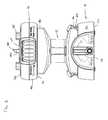
- FIG. 1is an isometric view of a fluid concentrator having exemplary features of aspects in accordance with the principles of the present disclosure.
- FIG. 2is a front view of the fluid concentrator of FIG. 1 .
- FIG. 3is a back view of the fluid concentrator of FIG. 1 .
- FIG. 4is a right side view of the fluid concentrator of FIG. 1 .
- FIG. 5is a left side view of the fluid concentrator of FIG. 1 .
- FIG. 6is a top view of the fluid concentrator of FIG. 1 .
- FIG. 7is a bottom view of the fluid concentrator of FIG. 1 .
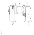
- FIG. 8is an isometric view of the fluid concentrator with a cartridge removed.
- FIG. 9is a front view of the fluid concentrator of FIG. 8 .
- FIG. 10is a back view of the fluid concentrator of FIG. 8 .
- FIG. 11is a right side view of the fluid concentrator of FIG. 8 .
- FIG. 12is a left side view of the fluid concentrator of FIG. 8 .
- FIG. 13is a top view of the fluid concentrator of FIG. 8 .
- FIG. 14is a left side view of the fluid concentrator of FIG. 1 with a separation chamber removed to show a valve assembly suitable for use with the fluid concentrator.
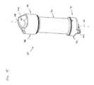
- FIG. 15is an isometric view of a cartridge that is suitable for use with the fluid concentrator of FIG. 1 .
- FIG. 16is an exploded isometric view of the cartridge of FIG. 15 .
- FIG. 17is an exploded isometric view of an alternate embodiment of a cartridge suitable for use with the fluid concentrator of FIG. 1 .
- FIG. 18is an isometric view of an interior region of a first end portion of the fluid concentrator of FIG. 1 .
- FIG. 19is a schematic representation of a fluid path through the fluid concentrator of FIG. 1 .
- body fluidrefers to a biological fluid collected from a subject.
- the subjectcan be a mammal, including but not limited to human, bovine, pig, sheep, horse, or goat.
- the body fluidscan be autologous.
- Body fluidsinclude, but are not limited to, blood, plasma, serum, urine, saliva, mucus, cerebrospinal fluid, lymphatic fluid, seminal fluid, amniotic fluid, vitreous fluid, as well as fluid collected from cell culture of patient cells, and the like.
- Body fluidscan also include tissue and cells such as, for example, bone, bone marrow, muscle tissue, brain, heart, liver, lung, stomach, small intestine, large intestine, colon, uterus ovary, testis, cartilage, soft tissue, skin, subcutaneous tissue, breast tissue, tissue obtained from other species, patient tissue from surgery, and the like.
- the body fluids of the present disclosurealso include, for example, bone marrow, fluids obtained from surgery, fluid filtrates, tissue filtrates or fragments, bone chips or fragments obtained during surgery, and the like.
- the fluid concentrator 10includes a main housing 12 having a first end portion 14 , an oppositely disposed second end portion 16 and a separation chamber 18 that extends between the first and second end portions 14 , 16 .
- the fluid concentrator 10further includes a cartridge 20 that is removably engaged to the main housing 12 .
- the cartridge 20which will be described in greater detail subsequently, is configured to be inserted and removed from the main housing 12 while the main housing 12 is intact. This capability is potentially advantageous, for example, as it allows for different sterilization processes to be employed for the main housing 12 and the cartridge 20 . In addition, it allows for the cartridge to be transported independently from the main housing 12 so that the contents of the cartridge can be subsequently independently processed (e.g., incubated, etc.).
- the cartridge 20is adapted to receive a material (e.g., objects, scaffolds (i.e., artificial structure capable of supporting tissue formation), graft materials, filters, cells, etc.).
- a materiale.g., objects, scaffolds (i.e., artificial structure capable of supporting tissue formation), graft materials, filters, cells, etc.
- the cartridge 20is in selective fluid communication with the separation chamber 18 so that fluid from the separation chamber 18 can be infused into the cartridge 20 .
- the first end portion 14 of the fluid concentrator 10is a base portion.
- the first end portion 14includes a first surface 22 , an oppositely disposed second surface 24 and a sidewall 26 that extends between the first and second surfaces 22 , 24 .
- the first surface 22is generally parallel to the second surface 24 .
- the first and second surfaces 22 , 24 and the sidewall 26 of the first end portion 14cooperatively define an interior cavity 28 (shown in FIG. 8 ).
- the second surface 24defines a cartridge opening 29 that extends through the second surface 24 .
- the cartridge opening 29is generally circular in shape.
- the cartridge opening 29provides access to the interior cavity 28 of the first end portion 14 .
- first end portion 14is generally cylindrical in shape. In another embodiment, the first end portion 14 is generally frusto-conical in shape. In the depicted embodiment, the sidewall 26 tapers toward the second surface 24 .
- the first end portion 14includes a base port 30 .
- the first end portion 14includes a first fluid port 30 a and a second fluid port 30 b .
- each of the first and second fluid ports 30 a , 30 bextends outwardly from the second surface 24 of the first end portion 14 .
- the first and second fluid ports 30 a , 30 bextend outwardly in a direction that is oblique relative to the second surface 24 .
- the first and second fluid ports 30 a , 30 bare angled toward the sidewall 26 .
- Each of the first and second fluid ports 30 a , 30 bincludes an interior port interface and an exterior port interface.
- the interior port interfaceis disposed in the interior cavity 28 of the first end portion 14 .
- the exterior port interfaceis accessible from an exterior of the fluid concentrator 10 .
- the interior port interfaces of the first and second fluid ports 30 a , 30 bare in fluid communication with at least one of the separation chamber 18 and the cartridge 20 through fluid conduits (e.g., tubing, flexible tubing, piping, etc.) disposed in the interior cavity 28 .
- the first fluid port 30 ais in selective fluid communication with the separation chamber 18 and the cartridge 20 .
- the second fluid port 30 bis in fluid communication with the cartridge 20 .
- Each of the first and second fluid ports 30 a , 30 bare selectively capped by a plug 32 .
- the plug 32is engaged with the exterior port interface.
- the plug 32is threadedly engaged with the exterior port interface of each of first and second fluid ports 30 a , 30 b , respectively.
- the second end portion 16 of the fluid concentrator 10is a top portion.
- the second end portion 16is generally aligned with the first end portion 14 .
- the second end portion 16is generally aligned along a central longitudinal axis 34 of the fluid concentrator 10 that extends through the first and second end portions 14 , 16 .
- the second end portion 16includes a first surface 36 , an oppositely disposed second surface 38 and a sidewall 40 that extends between the first and second surfaces 36 , 38 .
- the second end portion 16is generally disc-shaped (or puck-shaped).
- the sidewall 40is generally arcuate in shape so that the outer diameter of a central region 41 of the sidewall 40 is greater than an outer diameter of the sidewall 40 at the first surface 36 and an outer diameter of the sidewall 40 at the second surface 38 .
- the second end portion 16defines a cartridge passage 42 that extends through the first and second surfaces 36 , 38 .
- the cartridge passage 42includes an inner wall 43 that circumferentially surrounds the cartridge passage 42 .
- the cartridge passage 42is generally U-shaped and includes an opening in the sidewall 40 of the second end portion 16 .
- the cartridge passage 42is adapted to receive the cartridge 20 .
- the cartridge passage 42is configured so that the cartridge 20 can be inserted and removed from the fluid concentrator 10 while the main housing 12 is intact.
- the second end portion 16includes an inlet port 44 .
- the second end portion 16includes a first inlet port 44 a and a second inlet port 44 b .
- the first and second inlet ports 44 a , 44 bare configured to be in fluid communication with the separation chamber 18 .
- Each of the first and second inlet ports 44 a , 44 bincludes an interior port interface and an exterior port interface.
- the interior port interfaceis in fluid communication with the separation chamber 18 .
- the exterior port interfaceis accessible from an exterior of the fluid concentrator 10 .
- each of the first and second inlet ports 44 a , 44 bextends outwardly from the second surface 38 of the second end portion 16 .
- the first and second inlet ports 44 a , 44 bextend outwardly in a direction that is generally parallel to the central longitudinal axis 34 of the fluid concentrator 10 .
- Each of the first and second inlet ports 44 a , 44 bare selectively capped by a plug 45 .
- the plug 45is engaged with the exterior port interface.
- the plug 45is threadedly engaged with the exterior port interface of each of first and second inlet ports 44 a , 44 b , respectively.
- the separation chamber 18extends between the first and second end portions 14 , 16 .
- the separation chamber 18is adapted to contain a concentrated fluid.
- concentratedrefers to a fluid which has been separated by gravity, centrifugation, and/or filtration into various fractions.
- fractionrefers to the various components into which a biological fluid can be separated by centrifugation, gravitational weight separation and/or filtration. Each fraction is richer in a particular fluid component (i.e. concentrated) relative to the other fraction and the original fluid.
- the concentration processalso removes nonessential components such that the concentrated fraction contains only necessary or desired components.
- the separation chamber 18includes a first end 46 and an oppositely disposed second end 48 .
- the first end 46is engaged to the second surface 24 of the first end portion 14 while the second end 48 is engaged to the first surface 36 of the second end portion 16 .
- the separation chamber 18defines an interior cavity 50 .
- the interior cavity 50is adapted to receive fluid.
- the first and second inlet ports 44 a , 44 bare in fluid communication with the interior cavity 50 of the separation chamber 18 .
- the fluid concentrator 10includes a valve assembly 52 that is in fluid communication with the separation chamber 18 .
- the valve assembly 52defines a longitudinal axis 54 that is generally parallel to the central longitudinal axis 34 of the fluid concentrator 10 .
- the valve assembly 52includes a valve stem 56 that defines a fluid opening 58 .
- the valve stem 56is axially positionable along the longitudinal axis 54 in the interior cavity 50 of the separation chamber 18 . After centrifugation, the valve stem 56 can be axially positioned so that a height of the fluid opening 58 corresponds to a desired fluid layer.
- the fluid opening 58thus serves as an outlet port from which a fraction of fluid in the separation chamber 18 can be removed.
- the valve assembly 52further includes a valve adjustment knob 60 .
- the valve adjustment knob 60is adapted to rotate about the longitudinal axis 54 .
- the valve adjustment knob 60is in threaded engagement with the valve stem 56 .
- the fluid opening 58moves toward the first end portion 14 .
- the valve adjustment knob 60is rotated in an opposite second direction about the longitudinal axis 54 , the fluid opening 58 moves toward the second end portion 16 .
- valve adjustment knob 60is disposed in the second end portion 16 of the fluid concentrator 10 .
- a portion of the sidewall 40 , which is adjacent to the separation chamber 18 , of the second end portion 16is recessed so that a portion of the valve adjustment knob 60 can be accessed.
- the valve assembly 52further includes a control handle 62 .
- the control handle 62is moveable between a first position and a second position. In the first position, the fluid opening 58 is in fluid communication with the first fluid port 30 a in the first end portion 14 of the fluid concentrator 10 . In the second position, the first fluid port 30 a is in fluid communication with the cartridge 20 .
- the cartridge 20is shown.
- the cartridge 20is configured to be received by the first and second end portions 14 , 16 of the fluid concentrator 10 and to be in fluid communication with the separation chamber 18 .
- the cartridge 20includes a body 70 having a first axial end portion 72 and an oppositely disposed second axial end portion 74 .
- the body 70defines a bore 76 that extends through the first and second axial end portions 72 , 74 .
- the first axial end portion 72includes a first axial end 78 and a first shoulder 80 .
- the first shoulder 80extends radially outwardly from the body 70 .
- the first axial end portion 72defines a first groove 82 that is disposed between the first axial end 78 and the first shoulder 80 .
- the first groove 82is a circumferential groove defined in an outer surface 84 of the body 70 .
- the second axial end portion 74includes a second axial end 86 and a second shoulder 88 .
- the second shoulder 88extends radially outwardly from the body 70 .
- the second axial end portion 74defines a second groove 90 that is disposed between the second axial end 86 and the second shoulder 88 .
- the second groove 90is a circumferential groove defined in the outer surface 84 of the body 70 .
- the fluid concentratorhas numerous applications, including medical treatments and therapies, tissue regeneration, tissue culture, and cell culture.
- a body fluid or tissueis extracted from a patient.
- the extracted fluid or tissueis separated into different fractions in separation chamber 18 and a portion of a selected fraction is transferred to cartridge 20 via the ports.
- the selected fractionis passed through a material in cartridge 20 , such as a filter or separation medium, to form a concentrated product that can be used in medical treatments or surgical procedures.
- a material in cartridge 20such as a filter or separation medium
- the resultant concentrated productcan be used to treat a variety of conditions.
- concentrated body fluidscan be prepared as described above including, without limitation, blood fractions, platelet rich plasma (PRP), platelet poor plasma (PPP), stem cells (cord blood-derived and bone marrow-derived), concentrated seminal flood, concentrated spinal fluid, and the like.
- PRPplatelet rich plasma
- PPPplatelet poor plasma
- stem cellscord blood-derived and bone marrow-derived
- concentrated seminal floodconcentrated spinal fluid, and the like.
- the resultant productcan be used to treat a variety of medical conditions including, but not limited to a wound, soft tissue injury, or surgical site.
- the woundcan be a surgical incision, abrasion, ulcer, burn, or other break in the skin.
- the resultant productcan also be administered to treat an orthopedic disorder or during or after a surgical procedure to correct the orthopedic disorder to promote healing.
- orthopedic disordersinclude without limitation spinal fusion, spinal defect, bone trauma, cartilage damage, bone cyst, bone tumor, bone fracture, filling of osseous defect, joint augmentation, sinus augmentation, ridge preservation, joint revision, posterolateral fusion, and the like.
- cartridge 20can be configured as a growth chamber for the engineering and culturing of tissue and cells.
- Growth material, scaffold material, and the likecan be inserted into the cartridge and concentrated body fluids, tissues, and/or cells can be transferred from separation chamber 18 via the ports to the growth material or scaffold material in cartridge 20 .
- tissueis disrupted and then separated into fractions in separation chamber 18 .
- a desired cellular fractionis transferred from separation chamber 18 via the transfer ports to cartridge 20 configured with a growth material or scaffold.
- the cellular fractioncan be cultured within the fluid concentrator or cartridge 20 can be removed and cultured separately from the fluid concentrator.
- the bore 76 of the body 70is adapted to receive a material.
- the materialcan a separation medium, a filtration medium, a growth matrix or surface, scaffold, graft material or other material selected by a user. Separation and/or filtration media include affinity columns, packed bed matrices and beads.
- Nanofiber networkscan be used as filtration media or as a growth matrix or growth surface. Nanofiber networks and methods of making nanofiber networks are known and commercially available from Surmodics (Minneapolis, Minn.). See, for example, WO 2006/094076, U.S. 2005/0095695 and U.S. 2007/0082393.
- Objects such as a rod, screw, wire, mesh, or cagecan also be used as a growth surface or scaffold.
- the material inserted into bore 76 of the body 70is selected such that cartridge 20 can be utilized as a reaction chamber, holding chamber, or culture chamber to collect and retain separated fraction and/or filtered fluids or cells.
- the materialcan comprise an affinity membrane, support or column.
- Affinity columns used in chromatographic separation or purification of proteins and other biological macromoleculesmake use of specific binding interactions between molecules.
- a particular ligandis chemically immobilized or “coupled” to a solid support.
- Ligands that bind to general classes of proteins (such as, for example, receptors or antibodies) or commonly used fusion protein tags (such as, 6xHis)are commercially available in pre-immobilized forms ready to use for affinity purification.
- more specialized ligandssuch as specific antibodies, antigens or receptors of interest can be immobilized using one of several commercially available activated affinity supports.
- a peptide antigencan be immobilized to a support and used to purify antibodies that recognize the peptide.
- a receptor that binds a growth factor, differentiation factor, chemotactic factor, or adhesion moleculecan be immobilized to a support and used to purify said factors or molecules in the concentrated fraction of body fluids.
- Antibodies and receptors that bind growth factors, differentiation factors, chemotactic factors, or and/or adhesion molecules methods of making such antibodies and receptors, and methods of immobilizing the antibodies and receptors on a supportare known.
- One or more ligandscan be attached to the material.
- the ligandscan be selected to bind one or more particular growth factors, differentiation factors, chemotactic factors, and/or adhesion molecules.
- the ability to attach one or more selected ligands to the materialprovides for the creation of a custom body fluid, scaffold, or growth matrix, wherein the particular bioactive molecules comprising the concentrated body fluid, scaffold, or growth matrix are defined, for example, by the particular ligands, concentration of ligands, and/or ratio of one ligand to another selected by the user.
- Ligandscan be immobilized or “coupled” directly to a solid support material, growth surface, scaffold, and the like by formation of covalent chemical bonds between particular functional groups on the ligand and reactive groups on the support material, growth surface, or scaffold.
- functional groups and reactive groupsinclude, without limitation, primary amines, sulfhydryls, carboxylic acids, aldehydes, and the like.
- other coupling approachesare also possible.
- a GST-tagged fusion proteincan be first bound to an immobilized glutathione support by affinity interaction with the GST tag and then chemically cross-linked to the support. The immobilized GST-tagged fusion protein can then be used to affinity purify its binding partner(s).
- the materialcan comprise affinity or chromatography beads or particles.
- the beads or particlescan be, for example, glass, alginate, polymeric, or magnetic beads or particles.
- the beads or particlesfunction in the same way as affinity matrices or columns, but are significantly reduced in size, and are therefore particularly useful for microscale biological manipulations.
- an affinity column or affinity bead or particleis used as the material of the fluid concentrator 10 such that when a separated fluid or fluid fraction is passed over the beads or particles, those molecules or fluid components that have specific binding affinity to the ligand are retained on the beads, and can be retrieved or isolated by subsequent elution.
- the materialcan comprise a packed bed matrix or column.
- a packed bedis a bed of granular material which retains the solid particles as it passes, allowing fluids and liquids to be filtered free of solid contaminants or components.
- the granular material for the packed bedcan be sand, although celite or diatomaceous earth packed in a microscale container or loaded on top of a sintered-glass funnel can also serve as the packed bed.
- Incompressible diatomaceous earthi.e. primarily silica
- wood cellulose or other inert porous solidscan also be used as the granular material of the packed bed filter.
- a packed bed matrix or columnis used as the material of the fluid concentrator 10 such that when the separated fluid or fluid fraction is passed over the column, solid components or fluid components with a size greater than the pore size of the packed bed material are retained on the packed bed, while other fluid components pass through.
- the materialcan comprise a network of one or more nanofibers, a nanofibrillar structure, glass, silicon, or plastic comprising an etched or micropatterned surface, glass, silicon, or plastic surface comprising macropores or nanopores, or a polymer scaffold.
- Nanofiber networks of this typeare described in WO 2006/094076, U.S. 20050059695, and U.S. 20070082393 for example.
- the nanofiber networkcan be deposited on a surface of a substrate, and the combination of the nanofiber on the substrate can be a growth matrix or substrate, or as a filtration membrane.
- the substratecan be glass, polymeric, metallic, ceramic, cellulosic, or proteinaceous.
- Examples of a substrateinclude but are not limited to a rod, screw, wire, mesh, or cage.
- the nanofibrillar structure or nanofiber networkscan be utilized singly or layered to form a multi-layered assembly of nanofibrillar structures or nanofiber networks for cell or tissue culture.
- the nanofibrillar structureis used as a filter element or membrane of the concentrator device, such that when a separated fluid, fluid fraction, or cellular fraction is passed over the filter element, solid components or fluid components with a size greater than the pore size of the nanofibrillar material are retained on the material, while other fluid components pass through.
- the nanofibrillar structurecan be a growth matrix or scaffold, such that when the separated fluid, fluid fraction, or cellular fraction is passed over the matrix or scaffold, growth factors in the fluid, fluid fraction, or cellular fraction are retained on the matrix or scaffold and can be used to support subsequent cell or tissue growth.
- the cartridge 20further includes a first end cap 92 and a second end cap 94 .
- the first end cap 92is engaged to the first axial end portion 72 of the body 70 while the second end cap 94 is engaged to the second axial end portion 74 of the body 70 .
- the first and second end caps 92 , 94are sealingly engaged with the first and second axial end portions 72 , 74 , respectively.
- the first and second end caps 92 , 94are in threaded engagement with the first and second axial end portions 72 , 74 , respectively.
- the first and second end caps 92 , 94are in tight fitting engagement with the first and second axial end portion 72 , 74 .
- the first and second end caps 92 , 94are sonically welded to the first and second axial end portions 72 , 74 , respectively.
- a first sealprovides the sealing engagement between the first end cap 92 and the first axial end portion 72 while a second seal provides the sealing engagement between the second end cap 94 and the second axial end portion 74 .
- the first and second sealsare o-rings. In another embodiment, the first and second seals are gaskets.
- the first sealis disposed in the first groove 82 defined by the first axial end portion 72 .
- the second sealis disposed in the second groove 90 defined by the second axial end portion 74 .
- the first end cap 92defines a first cavity 100 that is adapted to receive the first axial end 78 of the body 70 of the cartridge 20 .
- the first end cap 92includes a first port 102 that is in fluid communication with the bore 76 of the body 70 when the first end cap 92 is disposed on the first axial end portion 72 of the cartridge 20 .
- the first end cap 92further includes a second port 103 (shown in FIGS. 18 and 19 ) that is in fluid communication with the bore 76 of the body 70 when the first end cap 92 is disposed on the first axial end portion 72 of the cartridge 20 .
- the first port 102is in selective fluid communication with the first fluid port 30 a while the second port 103 is in fluid communication with the second fluid port 30 b.
- the second end cap 94defines a second cavity that is adapted to receive the second axial end 86 of the body 70 .
- the second end cap 94includes a gripping portion 106 .
- the gripping portion 106includes a protrusion 108 that extends outwardly in a direction along a longitudinal axis 110 of the body 70 .
- the protrusion 108is adapted to be grasped by a hand of a user.
- FIG. 17an alternate embodiment of a cartridge 20 ′ is shown.
- the cartridge 20 ′is similar to the cartridge 20 that was previously described. It will be understood that the features disclosed with regard to the cartridge 20 could be used with the cartridge 20 ′.
- the cartridge 20 ′includes a body 70 ′ having a first axial end portion 72 ′ and an oppositely disposed second axial end portion 74 ′.
- the body 70 ′defines a bore 76 ′ that is adapted to receive the material.
- the bore 76 ′is further adapted to selectively receive fluid from the first fluid port 30 a of the fluid concentrator 10 .
- the cartridge 20 ′further includes a first end cap 92 ′ and a second end cap 94 ′.
- the first end cap 92 ′is engaged to the body 70 ′ at the first axial end portion 72 ′ while the second end cap 94 ′ is engaged to the body 70 ′ at the second axial end portion 74 ′.
- the first end cap 92 ′ of the cartridge 20 ′defines a first port 102 ′ and a second port.
- the first port 102 ′is in selective fluid communication with the first fluid port 30 a of the fluid concentrator 10 .
- the second portis in fluid communication with the second fluid port 30 b of the fluid concentrator 10 .
- the cartridge 20 ′further defines a third port 112 .
- the third port 112(shown schematically in FIG. 17 ) provides access to the bore 76 ′ of the body 70 ′ of the cartridge 20 ′.
- the third port 112is disposed adjacent to the second axial end portion 74 ′ of the cartridge 20 ′.
- the third port 112is disposed adjacent to the first axial end portion 72 ′.
- the third port 112is disposed between the first and second axial end portions 72 ′, 74 ′.
- the third port 112is defined by the first end cap 92 ′.
- the third port 112is defined by the second end cap 94 ′.
- the third port 112provides a location at which additional materials can be added or injected into the bore.
- the additional materialscan include cells, growth factors, food, drugs, chemicals, combinations thereof, etc.
- a first fluid conduit 120provides a selective fluid passage between the first fluid port 30 a in the first end portion 14 of the fluid concentrator 10 and the fluid opening 58 in the valve assembly 52 .
- a second fluid conduit 122provides a selective fluid passage between the valve assembly 52 and the port 102 of the cartridge 20 .
- a third conduit 124provides a fluid passage between the second fluid port 30 b and the second port 103 of the cartridge 20 .
- control handle 62is actuated between the first and second positions.
- first positionfluid communication between the separation chamber 18 and the first fluid port 30 a is established through the first fluid conduit 120 .
- second positionfluid communication between the first fluid port 30 a and the first port 102 of the cartridge 20 is established through the first and second fluid conduits 120 , 122 .
- Filtered fluidcan be removed from the second fluid port 30 b of the first end portion 14 of the fluid concentrator through the third conduit 124 .
- FIGS. 1 , 8 - 13 and 15 - 16the assembly of the cartridge 20 into the fluid concentrator 10 will be described.
- a filterdisposed in the bore 76 of the body 70 of the cartridge 20 and the first and second end caps 92 , 94 disposed on the first and second axial end portions 92 , 94
- the first end cap 92 and the first axial end portion 72 of the body 70are inserted through the cartridge passage 42 of the second end portion 16 of the fluid concentrator 10 in a direction toward the first end portion 14 .
- tubing 100shown in FIG.
- the cartridge 24is connected to the cartridge 20 to establish fluid communication between the cartridge 20 and the first and second fluid ports 30 a , 30 b and the separation chamber 18 .
- the first end cap 92 of the cartridge 20is inserted through the cartridge opening 29 of the second surface 24 of the first end portion 14 .
- a portion of the second end cap 94is disposed in the cartridge passage 42 of the second end portion 16 .
- Fluidis inserted through the inlet port 44 of the second end portion 16 .
- the fluidpasses through the inlet port 44 into the separation chamber 18 .
- the fluid concentrator 10is put into a centrifuge to separate the layers of the fluid. With the fluid separated, the valve adjustment knob 60 is actuated to position the fluid opening 58 of the valve stem 56 of the valve assembly 52 at the desired height of the fluid layer of interest.
- the filter element or membrane in the cartridge 20is not tolerant of centrifugation. In such instances, the cartridge 20 is disengaged from the main housing 12 prior to centrifugation and reengaged after centrifugation.
- the control handle 62is actuated to the first position, which provides fluid communication between the separation chamber 18 and the first fluid port 30 a . Fluid from the fluid layer is then withdrawn from the separation chamber 18 through the fluid opening 58 and through the first fluid port 30 a . In one embodiment, a syringe draws the fluid through the first fluid port 30 a.
- the control handle 62is actuated to second position, in which fluid communication is established between the first fluid port 30 a and the cartridge 20 .
- the fluidis then pushed into the first fluid port 30 a and the cartridge 20 .
- fluidis drawn out of the cartridge 20 through the second fluid port 30 b.
- the cartridge 20can be removed from the fluid concentrator 10 by pulling on the gripping portion 106 of the second end cap 94 of cartridge 20 in an axial direction away from the first end portion 14 of the fluid concentrator 10 .
- the first, second and third fluid conduits 120 , 122 , 124are disconnected and the cartridge 20 is pulled through the cartridge passage 42 of the second end portion 16 of the fluid concentrator 10 .
- the material disposed in the bore 76 of the cartridge 20can be replaced.
- a new cartridge 20can replace an existing cartridge 20 .
Landscapes
- Chemical & Material Sciences (AREA)
- Health & Medical Sciences (AREA)
- Life Sciences & Earth Sciences (AREA)
- Organic Chemistry (AREA)
- Zoology (AREA)
- Engineering & Computer Science (AREA)
- Bioinformatics & Cheminformatics (AREA)
- Wood Science & Technology (AREA)
- Chemical Kinetics & Catalysis (AREA)
- Microbiology (AREA)
- Biotechnology (AREA)
- Sustainable Development (AREA)
- Biomedical Technology (AREA)
- Molecular Biology (AREA)
- Biochemistry (AREA)
- General Engineering & Computer Science (AREA)
- General Health & Medical Sciences (AREA)
- Genetics & Genomics (AREA)
- Analytical Chemistry (AREA)
- Apparatus Associated With Microorganisms And Enzymes (AREA)
- Separation Using Semi-Permeable Membranes (AREA)
Abstract
Description
Claims (15)
Priority Applications (2)
| Application Number | Priority Date | Filing Date | Title |
|---|---|---|---|
| US13/041,962US9011684B2 (en) | 2011-03-07 | 2011-03-07 | Fluid concentrator with removable cartridge |
| PCT/US2012/027996WO2012122227A2 (en) | 2011-03-07 | 2012-03-07 | Fluid concentrator with removable cartridge |
Applications Claiming Priority (1)
| Application Number | Priority Date | Filing Date | Title |
|---|---|---|---|
| US13/041,962US9011684B2 (en) | 2011-03-07 | 2011-03-07 | Fluid concentrator with removable cartridge |
Publications (2)
| Publication Number | Publication Date |
|---|---|
| US20120231529A1 US20120231529A1 (en) | 2012-09-13 |
| US9011684B2true US9011684B2 (en) | 2015-04-21 |
Family
ID=46795921
Family Applications (1)
| Application Number | Title | Priority Date | Filing Date |
|---|---|---|---|
| US13/041,962Active2033-10-12US9011684B2 (en) | 2011-03-07 | 2011-03-07 | Fluid concentrator with removable cartridge |
Country Status (2)
| Country | Link |
|---|---|
| US (1) | US9011684B2 (en) |
| WO (1) | WO2012122227A2 (en) |
Cited By (3)
| Publication number | Priority date | Publication date | Assignee | Title |
|---|---|---|---|---|
| US9573130B2 (en) | 2013-04-02 | 2017-02-21 | Alliance Partners, Llc | Method of separating biological fluids into component parts using a fluids concentration cup assembly with hourglass shape |
| US11987787B2 (en) | 2020-07-22 | 2024-05-21 | AVITA Medical Americas, LLC | Devices, methods, and kits for preparing a cell suspension |
| US12180456B2 (en) | 2022-12-27 | 2024-12-31 | AVITA Medical Americas, LLC | Tissue healing |
Families Citing this family (3)
| Publication number | Priority date | Publication date | Assignee | Title |
|---|---|---|---|---|
| US7559925B2 (en) | 2006-09-15 | 2009-07-14 | Acclarent Inc. | Methods and devices for facilitating visualization in a surgical environment |
| EP3268461A1 (en)* | 2015-03-10 | 2018-01-17 | Arthrex, Inc. | Cellular component concentrator and filter apparatus |
| USD890294S1 (en)* | 2017-10-06 | 2020-07-14 | Claber S.P.A. | Container for dispensing liquids |
Citations (66)
| Publication number | Priority date | Publication date | Assignee | Title |
|---|---|---|---|---|
| US3669879A (en) | 1969-12-15 | 1972-06-13 | Dresser Ind | Fluid separation apparatus and method |
| US4230564A (en) | 1978-07-24 | 1980-10-28 | Keefer Bowie | Rotary reverse osmosis apparatus and method |
| US4327177A (en) | 1969-04-10 | 1982-04-27 | Wallace Shrimpton | Method and means for controlling the sex of mammalian offspring and product therefor |
| US4886597A (en) | 1987-09-24 | 1989-12-12 | Her Majesty The Queen In Right Of Canada | Centrifugal reverse-osmosis desalination unit |
| US5078864A (en)* | 1990-02-23 | 1992-01-07 | Nature's Sunshine Products, Inc. | High flow rate reverse osmosis water filtration system for home use |
| US5165938A (en) | 1984-11-29 | 1992-11-24 | Regents Of The University Of Minnesota | Wound healing agents derived from platelets |
| US5405607A (en) | 1989-06-23 | 1995-04-11 | Epstein; Gordon H. | Method for preparing fibrinogen adhesive from whole blood |
| US5663051A (en) | 1994-08-31 | 1997-09-02 | Activated Cell Therapy, Inc. | Separation apparatus and method |
| US5674394A (en) | 1995-03-24 | 1997-10-07 | Johnson & Johnson Medical, Inc. | Single use system for preparation of autologous plasma |
| US5733545A (en) | 1995-03-03 | 1998-03-31 | Quantic Biomedical Partners | Platelet glue wound sealant |
| US5788662A (en) | 1994-12-07 | 1998-08-04 | Plasmaseal Llc | Methods for making concentrated plasma and/or tissue sealant |
| US5840502A (en) | 1994-08-31 | 1998-11-24 | Activated Cell Therapy, Inc. | Methods for enriching specific cell-types by density gradient centrifugation |
| US5876321A (en) | 1995-04-14 | 1999-03-02 | Cobe Laboratories, Inc. | Control system for the spillover collection of sparse components such as mononuclear cells in a centrifuge apparatus |
| US5879280A (en) | 1995-04-14 | 1999-03-09 | Cobe Laboratories, Inc. | Intermittent collection of mononuclear cells in a centrifuge apparatus |
| US5891347A (en) | 1996-01-17 | 1999-04-06 | Matsumoto Machine Mfg. Co., Ltd. | Centrifugal filtration method and apparatus therefor |
| US6010627A (en) | 1995-06-06 | 2000-01-04 | Quantic Biomedical Partners | Device for concentrating plasma |
| US6027655A (en) | 1993-11-19 | 2000-02-22 | Bristol-Myers Squibb Company | Apparatus and method for centrifugally separating blood and then forming a fibrin monomer |
| US6071422A (en) | 1995-04-18 | 2000-06-06 | Cobe Laboratories, Inc. | Particle separation method and apparatus |
| US6106727A (en) | 1992-07-13 | 2000-08-22 | Pall Corporation | Automated system and method for processing biological fluid |
| US6132613A (en) | 1996-06-04 | 2000-10-17 | Her Majesty The Queen In Right Of Canada, As Represented By The Minister Of National Defence | Centrifugal reverse-osmosis desalination unit incorporating an annular membrane cartridge |
| EP1057534A1 (en) | 1999-06-03 | 2000-12-06 | Haemonetics Corporation | Centrifugation bowl with filter core |
| US6207066B1 (en) | 1996-07-23 | 2001-03-27 | Nuvue Technologies, L.L.C. | Method for purification of a blood component |
| US6299784B1 (en) | 1998-01-23 | 2001-10-09 | Fresenius Ag | Method and apparatus for processing intra- or postoperative blood loss for autotransfusion |
| US6354986B1 (en) | 2000-02-16 | 2002-03-12 | Gambro, Inc. | Reverse-flow chamber purging during centrifugal separation |
| US6398972B1 (en) | 1999-04-12 | 2002-06-04 | Harvest Technologies Corporation | Method for producing platelet rich plasma and/or platelet concentrate |
| US6524568B2 (en) | 1998-06-22 | 2003-02-25 | Cytomedix, Inc. | Enriched platelet wound healant |
| US6582386B2 (en) | 2001-03-06 | 2003-06-24 | Baxter International Inc. | Multi-purpose, automated blood and fluid processing systems and methods |
| US6582350B2 (en) | 2001-04-09 | 2003-06-24 | Medtronic, Inc. | Centrifuge container having curved linear shape |
| US6596180B2 (en) | 1996-04-30 | 2003-07-22 | Medtronic, Inc. | System and method for the production of autologous platelet gel |
| US20030233064A1 (en) | 2002-04-24 | 2003-12-18 | Interpore Orthopaedics | Blood separation and concentration system |
| US6706008B2 (en) | 2001-03-06 | 2004-03-16 | Baxter International Inc. | Automated system and method for withdrawing compounds from blood |
| US6716187B1 (en) | 1999-07-08 | 2004-04-06 | Implant Innovations, Inc. | Platelet concentration syringe kit |
| US6790371B2 (en) | 2001-04-09 | 2004-09-14 | Medtronic, Inc. | System and method for automated separation of blood components |
| US6793828B2 (en) | 2001-09-24 | 2004-09-21 | Medtronic, Inc. | Method of separating and collecting components from a fluid |
| US20040182795A1 (en) | 2003-03-21 | 2004-09-23 | Randel Dorian | Apparatus and method for concentration of plasma from whole blood |
| US6808503B2 (en) | 2001-03-06 | 2004-10-26 | Baxter International Inc. | Automated system and method for pre-surgical blood donation and fluid replacement |
| US6855263B2 (en) | 2002-07-23 | 2005-02-15 | Nuvue Technologies, Inc. | Rapid process for purification and concentration of plasmin |
| US6884228B2 (en) | 2001-03-06 | 2005-04-26 | Baxter International Inc. | Automated system adaptable for use with different fluid circuits |
| US20050095695A1 (en) | 2003-11-05 | 2005-05-05 | Shindler Melvin S. | Nanofibrillar structure and applications including cell and tissue culture |
| US20050184012A1 (en)* | 2004-02-23 | 2005-08-25 | Millennium Medical Technologies, Inc. | Fluid concentrator |
| WO2005094914A1 (en) | 2004-03-29 | 2005-10-13 | Smith & Nephew, Inc. | Preparation of a nucleated cell and/or platelet concentrate from a physiological solution |
| US20060060521A1 (en) | 2002-12-19 | 2006-03-23 | Utisol Technologies Ag | Filter device |
| US7077273B2 (en) | 2000-04-28 | 2006-07-18 | Harvest Technologies Corporation | Blood component separator disk |
| US20060175244A1 (en) | 2005-02-07 | 2006-08-10 | Hanuman Llc | Apparatus and method for preparing platelet rich plasma and concentrates thereof |
| US7223346B2 (en) | 2002-05-03 | 2007-05-29 | Hanuman Llc | Methods and apparatus for isolating platelets from blood |
| US7314460B2 (en) | 2003-11-24 | 2008-01-01 | Xep Med, Inc. | Extracorporeal pathogen reduction system |
| US20080108931A1 (en) | 2006-11-08 | 2008-05-08 | Bobroff Alec D | Adaptable Perioperative Cell-Salvage System and Methods and Disposable Units for Same |
| US7374678B2 (en) | 2002-05-24 | 2008-05-20 | Biomet Biologics, Inc. | Apparatus and method for separating and concentrating fluids containing multiple components |
| US20080166421A1 (en) | 2006-12-28 | 2008-07-10 | Michael Buhr | Method of surgical treatment using autologous conditioned plasma |
| US7476312B2 (en) | 2004-04-15 | 2009-01-13 | Trojan Technologies Inc. | Fluid treatment system |
| US7481941B2 (en) | 2003-12-23 | 2009-01-27 | Industrial Technology Research Institute | Method for separating components from blood plasma |
| US20090220482A1 (en) | 2008-02-27 | 2009-09-03 | Biomet Biologics, Llc | Methods and compositions for delivering interleukin-1 receptor antagonist |
| US7608258B2 (en) | 2002-04-13 | 2009-10-27 | Allan Mishra | Method for treatment of tendinosis using platelet rich plasma |
| US7695627B2 (en) | 2002-06-19 | 2010-04-13 | Northwest Biotherapeutics, Inc. | Tangential flow filtration devices and methods for leukocyte enrichment |
| US7694828B2 (en) | 2005-04-27 | 2010-04-13 | Biomet Manufacturing Corp. | Method and apparatus for producing autologous clotting components |
| US20100135969A1 (en) | 2003-12-29 | 2010-06-03 | Allan Mishra | Method of treating cancer using platelet releasate |
| US7766900B2 (en) | 2005-02-21 | 2010-08-03 | Biomet Manufacturing Corp. | Method and apparatus for application of a fluid |
| US7780860B2 (en) | 2002-05-24 | 2010-08-24 | Biomet Biologics, Llc | Apparatus and method for separating and concentrating fluids containing multiple components |
| US7806276B2 (en) | 2007-04-12 | 2010-10-05 | Hanuman, Llc | Buoy suspension fractionation system |
| US7811463B2 (en) | 2001-04-09 | 2010-10-12 | Arteriocyte Medical Systems, Inc. | Centrifuge apparatus and methods for on-line harvesting of a predetermined component of a fluid medium |
| US20100260815A1 (en) | 2007-06-22 | 2010-10-14 | Circle Biologics , LLC | Fluid concentrator, autologous concentrated body fluids, and uses thereof |
| US7833185B2 (en) | 2004-12-28 | 2010-11-16 | Caridianbct, Inc. | Apparatus for separating a volume of whole blood into at least three components |
| US7845499B2 (en) | 2002-05-24 | 2010-12-07 | Biomet Biologics, Llc | Apparatus and method for separating and concentrating fluids containing multiple components |
| US7867159B2 (en) | 2002-06-14 | 2011-01-11 | Arteriocyte Medical Systems, Inc. | Centrifuge system utilizing disposable components and automated processing of blood to collect platelet rich plasma |
| US7866485B2 (en) | 2005-02-07 | 2011-01-11 | Hanuman, Llc | Apparatus and method for preparing platelet rich plasma and concentrates thereof |
| US7897054B2 (en) | 2001-04-09 | 2011-03-01 | Arteriocyte Medical Systems, Inc. | Centrifuge container and methods of use |
- 2011
- 2011-03-07USUS13/041,962patent/US9011684B2/enactiveActive
- 2012
- 2012-03-07WOPCT/US2012/027996patent/WO2012122227A2/enactiveApplication Filing
Patent Citations (88)
| Publication number | Priority date | Publication date | Assignee | Title |
|---|---|---|---|---|
| US4327177A (en) | 1969-04-10 | 1982-04-27 | Wallace Shrimpton | Method and means for controlling the sex of mammalian offspring and product therefor |
| US3669879A (en) | 1969-12-15 | 1972-06-13 | Dresser Ind | Fluid separation apparatus and method |
| US4230564A (en) | 1978-07-24 | 1980-10-28 | Keefer Bowie | Rotary reverse osmosis apparatus and method |
| US5165938A (en) | 1984-11-29 | 1992-11-24 | Regents Of The University Of Minnesota | Wound healing agents derived from platelets |
| US4886597A (en) | 1987-09-24 | 1989-12-12 | Her Majesty The Queen In Right Of Canada | Centrifugal reverse-osmosis desalination unit |
| US5405607A (en) | 1989-06-23 | 1995-04-11 | Epstein; Gordon H. | Method for preparing fibrinogen adhesive from whole blood |
| US5078864A (en)* | 1990-02-23 | 1992-01-07 | Nature's Sunshine Products, Inc. | High flow rate reverse osmosis water filtration system for home use |
| US6106727A (en) | 1992-07-13 | 2000-08-22 | Pall Corporation | Automated system and method for processing biological fluid |
| US6027655A (en) | 1993-11-19 | 2000-02-22 | Bristol-Myers Squibb Company | Apparatus and method for centrifugally separating blood and then forming a fibrin monomer |
| US5663051A (en) | 1994-08-31 | 1997-09-02 | Activated Cell Therapy, Inc. | Separation apparatus and method |
| US5840502A (en) | 1994-08-31 | 1998-11-24 | Activated Cell Therapy, Inc. | Methods for enriching specific cell-types by density gradient centrifugation |
| US5788662A (en) | 1994-12-07 | 1998-08-04 | Plasmaseal Llc | Methods for making concentrated plasma and/or tissue sealant |
| US6214338B1 (en) | 1994-12-07 | 2001-04-10 | Plasmaseal Llc | Plasma concentrate and method of processing blood for same |
| US6063297A (en) | 1994-12-07 | 2000-05-16 | Plasmaseal Llc | Method and apparatus for making concentrated plasma and/or tissue sealant |
| US5733545A (en) | 1995-03-03 | 1998-03-31 | Quantic Biomedical Partners | Platelet glue wound sealant |
| US6001259A (en) | 1995-03-24 | 1999-12-14 | Johnson & Johnson Medical, Inc. | Preparation of autologous plasma and fibrin gel |
| US5674394A (en) | 1995-03-24 | 1997-10-07 | Johnson & Johnson Medical, Inc. | Single use system for preparation of autologous plasma |
| US5935437A (en) | 1995-03-24 | 1999-08-10 | Johnson & Johnson Medical, Inc. | Preparation of autologous plasma and fibrin gel |
| US6197194B1 (en) | 1995-03-24 | 2001-03-06 | Elaine Whitmore | Single use system for preparing autologous plasma and fibrin gel |
| US5879280A (en) | 1995-04-14 | 1999-03-09 | Cobe Laboratories, Inc. | Intermittent collection of mononuclear cells in a centrifuge apparatus |
| US5876321A (en) | 1995-04-14 | 1999-03-02 | Cobe Laboratories, Inc. | Control system for the spillover collection of sparse components such as mononuclear cells in a centrifuge apparatus |
| US6071422A (en) | 1995-04-18 | 2000-06-06 | Cobe Laboratories, Inc. | Particle separation method and apparatus |
| US6342157B1 (en) | 1995-06-06 | 2002-01-29 | Interpore Orthopedics, Inc. | Device and method for concentrating plasma |
| US6010627A (en) | 1995-06-06 | 2000-01-04 | Quantic Biomedical Partners | Device for concentrating plasma |
| US5891347A (en) | 1996-01-17 | 1999-04-06 | Matsumoto Machine Mfg. Co., Ltd. | Centrifugal filtration method and apparatus therefor |
| US7413652B2 (en) | 1996-04-30 | 2008-08-19 | Arteriocyte Medical Systems, Inc. | Method for the production of a blood component composition |
| US6596180B2 (en) | 1996-04-30 | 2003-07-22 | Medtronic, Inc. | System and method for the production of autologous platelet gel |
| US7811607B2 (en) | 1996-04-30 | 2010-10-12 | Arteriocyte Medical Systems, Inc. | Autologous fibrin sealant and method for making the same |
| US7838039B2 (en) | 1996-04-30 | 2010-11-23 | Arteriocyte Medical Systems, Inc. | Autologous fibrin sealant and method for making same |
| US20040132003A1 (en) | 1996-04-30 | 2004-07-08 | Dolecek Victor D. | Method for the production of a blood component composition |
| US6132613A (en) | 1996-06-04 | 2000-10-17 | Her Majesty The Queen In Right Of Canada, As Represented By The Minister Of National Defence | Centrifugal reverse-osmosis desalination unit incorporating an annular membrane cartridge |
| US6207066B1 (en) | 1996-07-23 | 2001-03-27 | Nuvue Technologies, L.L.C. | Method for purification of a blood component |
| US6299784B1 (en) | 1998-01-23 | 2001-10-09 | Fresenius Ag | Method and apparatus for processing intra- or postoperative blood loss for autotransfusion |
| US6524568B2 (en) | 1998-06-22 | 2003-02-25 | Cytomedix, Inc. | Enriched platelet wound healant |
| US6398972B1 (en) | 1999-04-12 | 2002-06-04 | Harvest Technologies Corporation | Method for producing platelet rich plasma and/or platelet concentrate |
| EP1057534A1 (en) | 1999-06-03 | 2000-12-06 | Haemonetics Corporation | Centrifugation bowl with filter core |
| US6716187B1 (en) | 1999-07-08 | 2004-04-06 | Implant Innovations, Inc. | Platelet concentration syringe kit |
| US7452344B2 (en) | 1999-07-08 | 2008-11-18 | Biomet 3I, Llc | Platelet concentration syringe kit |
| US6354986B1 (en) | 2000-02-16 | 2002-03-12 | Gambro, Inc. | Reverse-flow chamber purging during centrifugal separation |
| US7077273B2 (en) | 2000-04-28 | 2006-07-18 | Harvest Technologies Corporation | Blood component separator disk |
| US7547272B2 (en) | 2000-04-28 | 2009-06-16 | Harvest Technologies Corporation | Blood components separator disk |
| US6706008B2 (en) | 2001-03-06 | 2004-03-16 | Baxter International Inc. | Automated system and method for withdrawing compounds from blood |
| US6808503B2 (en) | 2001-03-06 | 2004-10-26 | Baxter International Inc. | Automated system and method for pre-surgical blood donation and fluid replacement |
| US6582386B2 (en) | 2001-03-06 | 2003-06-24 | Baxter International Inc. | Multi-purpose, automated blood and fluid processing systems and methods |
| US6884228B2 (en) | 2001-03-06 | 2005-04-26 | Baxter International Inc. | Automated system adaptable for use with different fluid circuits |
| US6582350B2 (en) | 2001-04-09 | 2003-06-24 | Medtronic, Inc. | Centrifuge container having curved linear shape |
| US7897054B2 (en) | 2001-04-09 | 2011-03-01 | Arteriocyte Medical Systems, Inc. | Centrifuge container and methods of use |
| US7811463B2 (en) | 2001-04-09 | 2010-10-12 | Arteriocyte Medical Systems, Inc. | Centrifuge apparatus and methods for on-line harvesting of a predetermined component of a fluid medium |
| US6790371B2 (en) | 2001-04-09 | 2004-09-14 | Medtronic, Inc. | System and method for automated separation of blood components |
| US6793828B2 (en) | 2001-09-24 | 2004-09-21 | Medtronic, Inc. | Method of separating and collecting components from a fluid |
| US7608258B2 (en) | 2002-04-13 | 2009-10-27 | Allan Mishra | Method for treatment of tendinosis using platelet rich plasma |
| US20030233064A1 (en) | 2002-04-24 | 2003-12-18 | Interpore Orthopaedics | Blood separation and concentration system |
| US7806845B2 (en) | 2002-04-24 | 2010-10-05 | Biomet Biologics, Llc | Blood separation and concentration system |
| US7470371B2 (en) | 2002-05-03 | 2008-12-30 | Hanuman Llc | Methods and apparatus for isolating platelets from blood |
| US7223346B2 (en) | 2002-05-03 | 2007-05-29 | Hanuman Llc | Methods and apparatus for isolating platelets from blood |
| US7954646B2 (en) | 2002-05-24 | 2011-06-07 | Biomet Biologics, Llc | Apparatus and method for separating and concentrating fluids containing multiple components |
| US7780860B2 (en) | 2002-05-24 | 2010-08-24 | Biomet Biologics, Llc | Apparatus and method for separating and concentrating fluids containing multiple components |
| US7374678B2 (en) | 2002-05-24 | 2008-05-20 | Biomet Biologics, Inc. | Apparatus and method for separating and concentrating fluids containing multiple components |
| US7845499B2 (en) | 2002-05-24 | 2010-12-07 | Biomet Biologics, Llc | Apparatus and method for separating and concentrating fluids containing multiple components |
| US7914689B2 (en) | 2002-05-24 | 2011-03-29 | Biomet Biologics, Llc | Apparatus and method for separating and concentrating fluids containing multiple components |
| US7867159B2 (en) | 2002-06-14 | 2011-01-11 | Arteriocyte Medical Systems, Inc. | Centrifuge system utilizing disposable components and automated processing of blood to collect platelet rich plasma |
| US7695627B2 (en) | 2002-06-19 | 2010-04-13 | Northwest Biotherapeutics, Inc. | Tangential flow filtration devices and methods for leukocyte enrichment |
| US6855263B2 (en) | 2002-07-23 | 2005-02-15 | Nuvue Technologies, Inc. | Rapid process for purification and concentration of plasmin |
| US20060060521A1 (en) | 2002-12-19 | 2006-03-23 | Utisol Technologies Ag | Filter device |
| US20040182795A1 (en) | 2003-03-21 | 2004-09-23 | Randel Dorian | Apparatus and method for concentration of plasma from whole blood |
| US20050095695A1 (en) | 2003-11-05 | 2005-05-05 | Shindler Melvin S. | Nanofibrillar structure and applications including cell and tissue culture |
| US7314460B2 (en) | 2003-11-24 | 2008-01-01 | Xep Med, Inc. | Extracorporeal pathogen reduction system |
| US7481941B2 (en) | 2003-12-23 | 2009-01-27 | Industrial Technology Research Institute | Method for separating components from blood plasma |
| US20100135969A1 (en) | 2003-12-29 | 2010-06-03 | Allan Mishra | Method of treating cancer using platelet releasate |
| US20120074073A1 (en) | 2004-02-23 | 2012-03-29 | Circle Biologics, Inc. | Fluid concentrator |
| US8012351B2 (en) | 2004-02-23 | 2011-09-06 | Circle Biologics, Inc. | Fluid concentrator |
| US7740760B2 (en) | 2004-02-23 | 2010-06-22 | Circle Biologics, Llc. | Fluid concentrator |
| US7803279B2 (en) | 2004-02-23 | 2010-09-28 | Circle Biologics, Llc. | Method of concentrating a component from a fluid |
| US20050184012A1 (en)* | 2004-02-23 | 2005-08-25 | Millennium Medical Technologies, Inc. | Fluid concentrator |
| US7354515B2 (en) | 2004-02-23 | 2008-04-08 | Millennium Medical Technologies, Inc. | Fluid concentrator |
| WO2005094914A1 (en) | 2004-03-29 | 2005-10-13 | Smith & Nephew, Inc. | Preparation of a nucleated cell and/or platelet concentrate from a physiological solution |
| US7476312B2 (en) | 2004-04-15 | 2009-01-13 | Trojan Technologies Inc. | Fluid treatment system |
| US7833185B2 (en) | 2004-12-28 | 2010-11-16 | Caridianbct, Inc. | Apparatus for separating a volume of whole blood into at least three components |
| US7824559B2 (en) | 2005-02-07 | 2010-11-02 | Hanumann, LLC | Apparatus and method for preparing platelet rich plasma and concentrates thereof |
| US20060175244A1 (en) | 2005-02-07 | 2006-08-10 | Hanuman Llc | Apparatus and method for preparing platelet rich plasma and concentrates thereof |
| US7866485B2 (en) | 2005-02-07 | 2011-01-11 | Hanuman, Llc | Apparatus and method for preparing platelet rich plasma and concentrates thereof |
| US7766900B2 (en) | 2005-02-21 | 2010-08-03 | Biomet Manufacturing Corp. | Method and apparatus for application of a fluid |
| US7694828B2 (en) | 2005-04-27 | 2010-04-13 | Biomet Manufacturing Corp. | Method and apparatus for producing autologous clotting components |
| US20080108931A1 (en) | 2006-11-08 | 2008-05-08 | Bobroff Alec D | Adaptable Perioperative Cell-Salvage System and Methods and Disposable Units for Same |
| US20080166421A1 (en) | 2006-12-28 | 2008-07-10 | Michael Buhr | Method of surgical treatment using autologous conditioned plasma |
| US7806276B2 (en) | 2007-04-12 | 2010-10-05 | Hanuman, Llc | Buoy suspension fractionation system |
| US20100260815A1 (en) | 2007-06-22 | 2010-10-14 | Circle Biologics , LLC | Fluid concentrator, autologous concentrated body fluids, and uses thereof |
| US20090220482A1 (en) | 2008-02-27 | 2009-09-03 | Biomet Biologics, Llc | Methods and compositions for delivering interleukin-1 receptor antagonist |
Non-Patent Citations (7)
| Title |
|---|
| Cell Factor Technologies, Inc., 2004, GPS Platelet Concentration System, 10 pages. |
| Harvest Technologies Corp., 2002, Developing Technologies for Accelerating Healing, Naturally, 6 pages. |
| International Search Report and Written Opinion cited in PCT/US05/13385 mailed Sep. 10, 2008. |
| International Search Report and Written Opinion mailed Sep. 24, 2012. |
| Medtronic Biologic Therapeutics & Diagnostics, 2002, Magellan Autologous Platelet Separator, 6 pages. |
| Osseous Technologies, Inc., Platelet Concentrate Collection System, Instructions for Use, 7 pages (2003). |
| Spectrum Labs.Com., 2002 "The ABCs of Filtration and Bioprocessing for the Third Millennium", "The ABCs of Filtration". |
Cited By (5)
| Publication number | Priority date | Publication date | Assignee | Title |
|---|---|---|---|---|
| US9573130B2 (en) | 2013-04-02 | 2017-02-21 | Alliance Partners, Llc | Method of separating biological fluids into component parts using a fluids concentration cup assembly with hourglass shape |
| US11987787B2 (en) | 2020-07-22 | 2024-05-21 | AVITA Medical Americas, LLC | Devices, methods, and kits for preparing a cell suspension |
| US12180456B2 (en) | 2022-12-27 | 2024-12-31 | AVITA Medical Americas, LLC | Tissue healing |
| US12270019B2 (en) | 2022-12-27 | 2025-04-08 | AVITA Medical Americas, LLC | Automated method |
| US12281298B2 (en) | 2022-12-27 | 2025-04-22 | AVITA Medical Americas, LLC | System for automated preparation of a regenerative epidermal suspension and related methods of use |
Also Published As
| Publication number | Publication date |
|---|---|
| WO2012122227A2 (en) | 2012-09-13 |
| WO2012122227A3 (en) | 2012-11-15 |
| US20120231529A1 (en) | 2012-09-13 |
Similar Documents
| Publication | Publication Date | Title |
|---|---|---|
| US9011684B2 (en) | Fluid concentrator with removable cartridge | |
| CN101801431B (en) | Fluid concentrator and autologous body fluid concentrate and method of use | |
| Tangen et al. | Gel filtration of blood platelets: a methodological report | |
| JP5946469B2 (en) | Polymeric sorbent for removal of impurities from whole blood and blood products | |
| EP2830765B1 (en) | Apparatus and method for separating and concentrating a component of a fluid | |
| US6008040A (en) | Procedures for efficient separation of cells, cellular materials and proteins | |
| KR101307672B1 (en) | Method for controlling propagation of umbilical cord blood hematopoietic stem cells and use thereof | |
| JP2008538514A (en) | Integrated system for collecting, processing and transplanting cell subsets including adult stem cells for regenerative medicine | |
| JP2010531142A5 (en) | ||
| EP2771087A1 (en) | A method for extracorporeal elimination of one or more components from blood | |
| RU2007107358A (en) | DEVICE AND METHOD FOR ISOLATING CELLS, BIOSPARTICLES AND / OR MOLECULES FROM LIQUIDS FOR PURPOSE IN ANIMALS, IN BIOTECHNOLOGY (INCLUDING BIOLOGICAL RESEARCH) AND MEDICAL DIAGNOSIS | |
| Yu | Adsorbents in blood purification: from lab search to clinical therapy | |
| US20180093032A1 (en) | Targeted apheresis using binding agents or ligands immobilized on membranes | |
| CN214286794U (en) | Biological particle purification device | |
| CN214300076U (en) | Membrane carrier purification device for biological particles | |
| JP2023104650A (en) | Method for separating and purifying extracellular vesicles | |
| CN112251320A (en) | Biological particle purification device and purification method | |
| EP3440093B1 (en) | Methods and devices for the enrichment of immunoglobulin from blood | |
| EP4051403A1 (en) | Adsorbent and a kit containing said adsorbent in a column | |
| JP2006160731A (en) | Blood ingredient-recovering apparatus | |
| US8283169B1 (en) | Differential gradient separation of cells | |
| WO2005099789A1 (en) | Treatment of sepsis | |
| CN111110915A (en) | Manufacturing method and application of autologous growth factor patch for constructing musculoskeletal tissue | |
| JPS6083666A (en) | Body fluids treating apparatus | |
| GB2445073A (en) | Cell separation device |
Legal Events
| Date | Code | Title | Description |
|---|---|---|---|
| AS | Assignment | Owner name:CIRCLE BIOLOGICS, LLC, MINNESOTA Free format text:ASSIGNMENT OF ASSIGNORS INTEREST;ASSIGNOR:KYLE, MATTHEW R.;REEL/FRAME:026449/0460 Effective date:20110406 | |
| AS | Assignment | Owner name:CIRCLE BIOLOGICS, INC., MINNESOTA Free format text:ASSIGNMENT OF ASSIGNORS INTEREST;ASSIGNOR:CIRCLE BIOLOGICS, LLC;REEL/FRAME:026665/0944 Effective date:20110725 | |
| AS | Assignment | Owner name:SPINESMITH HOLDINGS, LLC, TEXAS Free format text:ASSIGNMENT OF ASSIGNORS INTEREST;ASSIGNOR:CIRCLE BIOLOGICS, INC.;REEL/FRAME:034251/0810 Effective date:20140820 | |
| AS | Assignment | Owner name:SILICON VALLEY BANK, CALIFORNIA Free format text:SECURITY INTEREST;ASSIGNOR:SPINESMITH HOLDINGS, LLC;REEL/FRAME:035014/0066 Effective date:20150110 | |
| STCF | Information on status: patent grant | Free format text:PATENTED CASE | |
| AS | Assignment | Owner name:BLUEARC MEZZANINE PARTNERS I, L.P., GEORGIA Free format text:SECURITY INTEREST;ASSIGNOR:SPINESMITH HOLDINGS, LLC;REEL/FRAME:042071/0370 Effective date:20170315 | |
| AS | Assignment | Owner name:AMERICAN BANK, N.A., TEXAS Free format text:SECURITY INTEREST;ASSIGNOR:SPINESMITH HOLDINGS, LLC;REEL/FRAME:044882/0096 Effective date:20171206 | |
| MAFP | Maintenance fee payment | Free format text:PAYMENT OF MAINTENANCE FEE, 4TH YR, SMALL ENTITY (ORIGINAL EVENT CODE: M2551); ENTITY STATUS OF PATENT OWNER: SMALL ENTITY Year of fee payment:4 | |
| AS | Assignment | Owner name:BLUEARC MEZZANINE PARTNERS I, LP, GEORGIA Free format text:SECURITY INTEREST;ASSIGNOR:SPINESMITH HOLDINGS, LLC;REEL/FRAME:048839/0655 Effective date:20190329 | |
| AS | Assignment | Owner name:SPINESMITH HOLDINGS, LLC, TEXAS Free format text:RELEASE BY SECURED PARTY;ASSIGNOR:SILICON VALLEY BANK;REEL/FRAME:048853/0183 Effective date:20190408 Owner name:SPINESMITH HOLIDNGS, LLC, TEXAS Free format text:RELEASE BY SECURED PARTY;ASSIGNOR:AMERICAN BANK;REEL/FRAME:048853/0105 Effective date:20190328 | |
| MAFP | Maintenance fee payment | Free format text:PAYMENT OF MAINTENANCE FEE, 8TH YR, SMALL ENTITY (ORIGINAL EVENT CODE: M2552); ENTITY STATUS OF PATENT OWNER: SMALL ENTITY Year of fee payment:8 |