US9011542B2 - Intervertebral prosthesis endplate having double dome and surgical tools for implanting same - Google Patents
Intervertebral prosthesis endplate having double dome and surgical tools for implanting sameDownload PDFInfo
- Publication number
- US9011542B2 US9011542B2US11/862,012US86201207AUS9011542B2US 9011542 B2US9011542 B2US 9011542B2US 86201207 AUS86201207 AUS 86201207AUS 9011542 B2US9011542 B2US 9011542B2
- Authority
- US
- United States
- Prior art keywords
- endplate
- elevated region
- base plate
- periphery
- circular arcs
- Prior art date
- Legal status (The legal status is an assumption and is not a legal conclusion. Google has not performed a legal analysis and makes no representation as to the accuracy of the status listed.)
- Active, expires
Links
Images


Classifications
- A—HUMAN NECESSITIES
- A61—MEDICAL OR VETERINARY SCIENCE; HYGIENE
- A61B—DIAGNOSIS; SURGERY; IDENTIFICATION
- A61B17/00—Surgical instruments, devices or methods
- A61B17/16—Instruments for performing osteoclasis; Drills or chisels for bones; Trepans
- A61B17/1662—Instruments for performing osteoclasis; Drills or chisels for bones; Trepans for particular parts of the body
- A61B17/1671—Instruments for performing osteoclasis; Drills or chisels for bones; Trepans for particular parts of the body for the spine
- A—HUMAN NECESSITIES
- A61—MEDICAL OR VETERINARY SCIENCE; HYGIENE
- A61B—DIAGNOSIS; SURGERY; IDENTIFICATION
- A61B17/00—Surgical instruments, devices or methods
- A61B17/16—Instruments for performing osteoclasis; Drills or chisels for bones; Trepans
- A61B17/1659—Surgical rasps, files, planes, or scrapers
- A—HUMAN NECESSITIES
- A61—MEDICAL OR VETERINARY SCIENCE; HYGIENE
- A61F—FILTERS IMPLANTABLE INTO BLOOD VESSELS; PROSTHESES; DEVICES PROVIDING PATENCY TO, OR PREVENTING COLLAPSING OF, TUBULAR STRUCTURES OF THE BODY, e.g. STENTS; ORTHOPAEDIC, NURSING OR CONTRACEPTIVE DEVICES; FOMENTATION; TREATMENT OR PROTECTION OF EYES OR EARS; BANDAGES, DRESSINGS OR ABSORBENT PADS; FIRST-AID KITS
- A61F2/00—Filters implantable into blood vessels; Prostheses, i.e. artificial substitutes or replacements for parts of the body; Appliances for connecting them with the body; Devices providing patency to, or preventing collapsing of, tubular structures of the body, e.g. stents
- A61F2/02—Prostheses implantable into the body
- A61F2/30—Joints
- A61F2/30767—Special external or bone-contacting surface, e.g. coating for improving bone ingrowth
- A61F2/30771—Special external or bone-contacting surface, e.g. coating for improving bone ingrowth applied in original prostheses, e.g. holes or grooves
- A—HUMAN NECESSITIES
- A61—MEDICAL OR VETERINARY SCIENCE; HYGIENE
- A61F—FILTERS IMPLANTABLE INTO BLOOD VESSELS; PROSTHESES; DEVICES PROVIDING PATENCY TO, OR PREVENTING COLLAPSING OF, TUBULAR STRUCTURES OF THE BODY, e.g. STENTS; ORTHOPAEDIC, NURSING OR CONTRACEPTIVE DEVICES; FOMENTATION; TREATMENT OR PROTECTION OF EYES OR EARS; BANDAGES, DRESSINGS OR ABSORBENT PADS; FIRST-AID KITS
- A61F2/00—Filters implantable into blood vessels; Prostheses, i.e. artificial substitutes or replacements for parts of the body; Appliances for connecting them with the body; Devices providing patency to, or preventing collapsing of, tubular structures of the body, e.g. stents
- A61F2/02—Prostheses implantable into the body
- A61F2/30—Joints
- A61F2/44—Joints for the spine, e.g. vertebrae, spinal discs
- A61F2/442—Intervertebral or spinal discs, e.g. resilient
- A—HUMAN NECESSITIES
- A61—MEDICAL OR VETERINARY SCIENCE; HYGIENE
- A61F—FILTERS IMPLANTABLE INTO BLOOD VESSELS; PROSTHESES; DEVICES PROVIDING PATENCY TO, OR PREVENTING COLLAPSING OF, TUBULAR STRUCTURES OF THE BODY, e.g. STENTS; ORTHOPAEDIC, NURSING OR CONTRACEPTIVE DEVICES; FOMENTATION; TREATMENT OR PROTECTION OF EYES OR EARS; BANDAGES, DRESSINGS OR ABSORBENT PADS; FIRST-AID KITS
- A61F2/00—Filters implantable into blood vessels; Prostheses, i.e. artificial substitutes or replacements for parts of the body; Appliances for connecting them with the body; Devices providing patency to, or preventing collapsing of, tubular structures of the body, e.g. stents
- A61F2/02—Prostheses implantable into the body
- A61F2/30—Joints
- A61F2/46—Special tools for implanting artificial joints
- A61F2/4603—Special tools for implanting artificial joints for insertion or extraction of endoprosthetic joints or of accessories thereof
- A61F2/4611—Special tools for implanting artificial joints for insertion or extraction of endoprosthetic joints or of accessories thereof of spinal prostheses
- A—HUMAN NECESSITIES
- A61—MEDICAL OR VETERINARY SCIENCE; HYGIENE
- A61F—FILTERS IMPLANTABLE INTO BLOOD VESSELS; PROSTHESES; DEVICES PROVIDING PATENCY TO, OR PREVENTING COLLAPSING OF, TUBULAR STRUCTURES OF THE BODY, e.g. STENTS; ORTHOPAEDIC, NURSING OR CONTRACEPTIVE DEVICES; FOMENTATION; TREATMENT OR PROTECTION OF EYES OR EARS; BANDAGES, DRESSINGS OR ABSORBENT PADS; FIRST-AID KITS
- A61F2/00—Filters implantable into blood vessels; Prostheses, i.e. artificial substitutes or replacements for parts of the body; Appliances for connecting them with the body; Devices providing patency to, or preventing collapsing of, tubular structures of the body, e.g. stents
- A61F2/02—Prostheses implantable into the body
- A61F2/30—Joints
- A61F2002/30001—Additional features of subject-matter classified in A61F2/28, A61F2/30 and subgroups thereof
- A61F2002/30003—Material related properties of the prosthesis or of a coating on the prosthesis
- A61F2002/3006—Properties of materials and coating materials
- A61F2002/30069—Properties of materials and coating materials elastomeric
- A—HUMAN NECESSITIES
- A61—MEDICAL OR VETERINARY SCIENCE; HYGIENE
- A61F—FILTERS IMPLANTABLE INTO BLOOD VESSELS; PROSTHESES; DEVICES PROVIDING PATENCY TO, OR PREVENTING COLLAPSING OF, TUBULAR STRUCTURES OF THE BODY, e.g. STENTS; ORTHOPAEDIC, NURSING OR CONTRACEPTIVE DEVICES; FOMENTATION; TREATMENT OR PROTECTION OF EYES OR EARS; BANDAGES, DRESSINGS OR ABSORBENT PADS; FIRST-AID KITS
- A61F2/00—Filters implantable into blood vessels; Prostheses, i.e. artificial substitutes or replacements for parts of the body; Appliances for connecting them with the body; Devices providing patency to, or preventing collapsing of, tubular structures of the body, e.g. stents
- A61F2/02—Prostheses implantable into the body
- A61F2/30—Joints
- A61F2002/30001—Additional features of subject-matter classified in A61F2/28, A61F2/30 and subgroups thereof
- A61F2002/30108—Shapes
- A61F2002/3011—Cross-sections or two-dimensional shapes
- A61F2002/30112—Rounded shapes, e.g. with rounded corners
- A61F2002/30125—Rounded shapes, e.g. with rounded corners elliptical or oval
- A—HUMAN NECESSITIES
- A61—MEDICAL OR VETERINARY SCIENCE; HYGIENE
- A61F—FILTERS IMPLANTABLE INTO BLOOD VESSELS; PROSTHESES; DEVICES PROVIDING PATENCY TO, OR PREVENTING COLLAPSING OF, TUBULAR STRUCTURES OF THE BODY, e.g. STENTS; ORTHOPAEDIC, NURSING OR CONTRACEPTIVE DEVICES; FOMENTATION; TREATMENT OR PROTECTION OF EYES OR EARS; BANDAGES, DRESSINGS OR ABSORBENT PADS; FIRST-AID KITS
- A61F2/00—Filters implantable into blood vessels; Prostheses, i.e. artificial substitutes or replacements for parts of the body; Appliances for connecting them with the body; Devices providing patency to, or preventing collapsing of, tubular structures of the body, e.g. stents
- A61F2/02—Prostheses implantable into the body
- A61F2/30—Joints
- A61F2002/30001—Additional features of subject-matter classified in A61F2/28, A61F2/30 and subgroups thereof
- A61F2002/30316—The prosthesis having different structural features at different locations within the same prosthesis; Connections between prosthetic parts; Special structural features of bone or joint prostheses not otherwise provided for
- A61F2002/30535—Special structural features of bone or joint prostheses not otherwise provided for
- A61F2002/30563—Special structural features of bone or joint prostheses not otherwise provided for having elastic means or damping means, different from springs, e.g. including an elastomeric core or shock absorbers
- A—HUMAN NECESSITIES
- A61—MEDICAL OR VETERINARY SCIENCE; HYGIENE
- A61F—FILTERS IMPLANTABLE INTO BLOOD VESSELS; PROSTHESES; DEVICES PROVIDING PATENCY TO, OR PREVENTING COLLAPSING OF, TUBULAR STRUCTURES OF THE BODY, e.g. STENTS; ORTHOPAEDIC, NURSING OR CONTRACEPTIVE DEVICES; FOMENTATION; TREATMENT OR PROTECTION OF EYES OR EARS; BANDAGES, DRESSINGS OR ABSORBENT PADS; FIRST-AID KITS
- A61F2/00—Filters implantable into blood vessels; Prostheses, i.e. artificial substitutes or replacements for parts of the body; Appliances for connecting them with the body; Devices providing patency to, or preventing collapsing of, tubular structures of the body, e.g. stents
- A61F2/02—Prostheses implantable into the body
- A61F2/30—Joints
- A61F2/30767—Special external or bone-contacting surface, e.g. coating for improving bone ingrowth
- A61F2/30771—Special external or bone-contacting surface, e.g. coating for improving bone ingrowth applied in original prostheses, e.g. holes or grooves
- A61F2002/30878—Special external or bone-contacting surface, e.g. coating for improving bone ingrowth applied in original prostheses, e.g. holes or grooves with non-sharp protrusions, for instance contacting the bone for anchoring, e.g. keels, pegs, pins, posts, shanks, stems, struts
- A61F2002/30884—Fins or wings, e.g. longitudinal wings for preventing rotation within the bone cavity
- A—HUMAN NECESSITIES
- A61—MEDICAL OR VETERINARY SCIENCE; HYGIENE
- A61F—FILTERS IMPLANTABLE INTO BLOOD VESSELS; PROSTHESES; DEVICES PROVIDING PATENCY TO, OR PREVENTING COLLAPSING OF, TUBULAR STRUCTURES OF THE BODY, e.g. STENTS; ORTHOPAEDIC, NURSING OR CONTRACEPTIVE DEVICES; FOMENTATION; TREATMENT OR PROTECTION OF EYES OR EARS; BANDAGES, DRESSINGS OR ABSORBENT PADS; FIRST-AID KITS
- A61F2/00—Filters implantable into blood vessels; Prostheses, i.e. artificial substitutes or replacements for parts of the body; Appliances for connecting them with the body; Devices providing patency to, or preventing collapsing of, tubular structures of the body, e.g. stents
- A61F2/02—Prostheses implantable into the body
- A61F2/30—Joints
- A61F2/30767—Special external or bone-contacting surface, e.g. coating for improving bone ingrowth
- A61F2002/3092—Special external or bone-contacting surface, e.g. coating for improving bone ingrowth having an open-celled or open-pored structure
- A—HUMAN NECESSITIES
- A61—MEDICAL OR VETERINARY SCIENCE; HYGIENE
- A61F—FILTERS IMPLANTABLE INTO BLOOD VESSELS; PROSTHESES; DEVICES PROVIDING PATENCY TO, OR PREVENTING COLLAPSING OF, TUBULAR STRUCTURES OF THE BODY, e.g. STENTS; ORTHOPAEDIC, NURSING OR CONTRACEPTIVE DEVICES; FOMENTATION; TREATMENT OR PROTECTION OF EYES OR EARS; BANDAGES, DRESSINGS OR ABSORBENT PADS; FIRST-AID KITS
- A61F2230/00—Geometry of prostheses classified in groups A61F2/00 - A61F2/26 or A61F2/82 or A61F9/00 or A61F11/00 or subgroups thereof
- A61F2230/0002—Two-dimensional shapes, e.g. cross-sections
- A61F2230/0004—Rounded shapes, e.g. with rounded corners
- A61F2230/0008—Rounded shapes, e.g. with rounded corners elliptical or oval
- A—HUMAN NECESSITIES
- A61—MEDICAL OR VETERINARY SCIENCE; HYGIENE
- A61F—FILTERS IMPLANTABLE INTO BLOOD VESSELS; PROSTHESES; DEVICES PROVIDING PATENCY TO, OR PREVENTING COLLAPSING OF, TUBULAR STRUCTURES OF THE BODY, e.g. STENTS; ORTHOPAEDIC, NURSING OR CONTRACEPTIVE DEVICES; FOMENTATION; TREATMENT OR PROTECTION OF EYES OR EARS; BANDAGES, DRESSINGS OR ABSORBENT PADS; FIRST-AID KITS
- A61F2230/00—Geometry of prostheses classified in groups A61F2/00 - A61F2/26 or A61F2/82 or A61F9/00 or A61F11/00 or subgroups thereof
- A61F2230/0063—Three-dimensional shapes
- A61F2230/0073—Quadric-shaped
- A61F2230/008—Quadric-shaped paraboloidal
Definitions
- This inventionrelates to prostheses for replacing a human intervertebral disc and instruments for implanting such a prosthesis, and more particularly to an endplate for such a prosthesis having a domed surface for contacting an adjacent vertebra in a human spinal motion segment.
- the human spinal columnachieves its remarkable combination of strong support and appropriate flexibility by reason of its structure comprising bony vertebrae separated by intervertebral discs of softer and flexible tissue that allow limited motion between adjacent vertebrae in flexion-extension, lateral bending, and torsion.
- Each individual flexible element of the spinecomprising a pair of adjacent vertebrae separated by an intervertebral disc, constitutes a spinal motion segment.
- the proper function of such a spinal motion segmentrequires the intervertebral disc to provide proper separation between the vertebrae while allowing sufficient relative motion in the median, coronal and transverse anatomical planes of the body. While each intervertebral disc typically performs its function effectively without conscious awareness, the disc and surrounding tissues are provided with ample innervation that informs the individual of any damage and/or malfunction by providing a pain signal.
- the spinal regions most susceptible to painful pathology of the intervertebral discare the cervical and lumbar regions. Such painful pathology is typically the result of some traumatic injury or age-related changes in the structure and function of the intervertebral disc.
- DDDdegenerative disc disease
- the most common pathologic condition causing chronic low back pain and neck painis degenerative disc disease (DDD), which is typically the result of age-related changes in the tissues constituting the intervertebral disc, with accompanying abnormalities, e.g., deformation, in the functional structures of the disc.
- DDDdegenerative disc disease
- Even normal movement between the adjacent vertebraecan cause pain, which may become chronic and sufficiently severe to result in significant disability.
- non-invasive treatmentfails to relieve chronic disabling back pain caused by such disease, recourse is had to surgical intervention.
- palliative surgical proceduressuch as disc excision, decompression, and/or spinal fusion have been performed to relieve intractable pain of patients with degenerative disc disease.
- artificial intervertebral disc prostheseshave been developed, which have made it possible to replace a degenerated disc with such a prosthesis to achieve pain relief and restore anatomical function.
- intervertebral disc prosthesisA number of factors must be considered in the design of an intervertebral disc prosthesis if a successful outcome of disc arthroplasty is to be expected.
- the prosthesis designmust provide for proper positioning, correct alignment, congruent contact surface area, and immediate post-operative prosthetic stability within the disc space.
- the conformation of the vertebra-contacting surface of the prosthesis at the vertebra-prosthesis interfaceis of significant importance, particularly for post-operative stability of the prosthesis in the intervertebral space.
- the clinical results of intervertebral disc arthroplastyare closely correlated to the proper initial positioning of the disc prosthesis in the disc space and subsequent maintenance thereof. For instance, if an implanted disc prosthesis does not maintain a stable position within the intervertebral space, the patient may experience post-operative accelerated disc degeneration in adjacent spinal motion segments, as well as formation of osteophytic growths on the vertebrae.
- Another possible post-operative complicationis subsidence of the disc prosthesis into an adjacent vertebra.
- Such instabilityis related to at least three factors: contact area between the prosthesis and the adjacent vertebral body, bone mineral density in the contacting surface of the vertebral body, and applied load.
- the effective prosthesis-vertebra contact areais affected by the variable curvature and irregular surface profile of the adjacent vertebra, both of which vary significantly from patient to patient, e.g., in the lumbosacral spine which is the site of many intervertebral disc arthroplasties.
- intervertebral disc prosthesesThe great variety of designs that have been proposed for the bone-contacting surface of intervertebral disc prostheses can be taken as evidence that an ideal design has yet to be achieved. Examples of such prostheses have included those with relatively flat vertebra-contacting surfaces, those with domed profiles, or those incorporating other specially configured shapes such as corrugated or serrated surfaces or protruded platforms.
- intervertebral disc prostheseshave incorporated additional structures to enhance the security of fixation to the vertebral bone. Some designs have incorporated provisions for fixation using screws driven either into the anterior or lateral sides of the adjacent vertebrae or into the vertebral endplate itself.
- the bone-contacting surfaces of other prostheseshave been provided with spikes, keels, serrations, or the like, in order to provide stable fixation of the prosthesis.
- Some intervertebral prostheseshave incorporated endplates having dome-shaped surfaces for contact with the adjacent vertebral bodies. Both spherical domes and ellipsoidal domes have been employed. Ellipsoidal domes better approximate the planform of a vertebral body, and, when seated in a corresponding ellipsoidal seat reamed in the endplate of the vertebral body, provide a measure of torsional stability. However, preparation of such an ellipsoidal seat and proper alignment with the vertebrae can present some surgical difficulties. Spherical domes, having a circular planform, are more easily fitted to a prepared seat, but, by themselves, tend to provide less torsional stability.
- an endplate for an intervertebral disc prosthesisthat promotes a stable relationship between the prosthesis and the adjacent vertebrae after implantation.
- the inventionalso encompasses tools for preparing a seat or recess in a vertebral body to provide a congruent fit for the endplate of the invention, as well as a surgical procedure for preparing a surgical site and implanting a prosthesis using an endplate of the invention.
- the prosthesis endplate of the inventioncomprises:
- a generally planar base platehaving a periphery sized and configured to fit within an intervertebral space of a human spinal motion segment
- a second elevated region, or domewithin the boundary of the first elevated region.
- the antero-posterior and side-to-side (medial-lateral) dimensions of the first elevated regionare made to be unequal in order to provide resistance to torsional movement between the prosthesis endplate and the adjacent vertebral body under the normal stresses produced by the physiological motion of the spinal motion segment.
- the laterally opposite sidewalls of the first elevated regionare defined by arcs that terminate in sagittal planes of the endplate, and are symmetrical with respect to a coronal plane of the endplate.
- the arcs terminating the lateral side portions of the first elevated regionare circular arcs centered in sagittal planes of the endplate, and may or may not be symmetrical with respect to a coronal plane of the endplate.
- the second elevated regionis generally dome-shaped, and the laterally opposite side portions are defined by circular arcs having a common center located in the median plane of the endplate.
- a bone rasp apparatus for forming a recess or seat in a vertebral body for receiving a prosthesis endplateincludes at least one bone rasp tool that includes a rasp head and a handle for manipulating the head within an intervertebral space.
- the rasp headincludes a pivot member that can be inserted into a recess formed in the vertebral body endplate rasp teeth arranged on the rasp head to prepare at least a portion of a recess or seat for a vertebral endplate when the rasp head is reciprocally rotated about the pivot member.
- a groove-cutter for preparing an antero-posterior groove in a vertebral body to receive a fin or keel of an intervertebral disk prosthesis endplateincludes a cutter guide member having a handle and a guide head sized and configured to be seated in a recess or seat previously formed in a vertebral body.
- the groove-cutteris provided with an antero-posterior guide slot that guides the antero-posterior reciprocating cutter and a stowage recess for stowing the cutter in a protected position while the guide head is inserted into the intervertebral space.
- the cutteris mounted on a reciprocable and rotatable shaft that actuates the cutter by an antero-posterior reciprocating motion and can be rotated to place the cutter in the stowage recess.
- one feature of the inventionis an endplate for an intervertebral disc prosthesis that has a dome configuration which provides for improved stability under imposed stresses that tend to produce torsional instability and/or extrusion of the prosthesis from the intervertebral space.
- a further feature of the inventionis an endplate for an intervertebral disc prosthesis that will facilitate reliable and easy positioning, alignment, preparation of a congruent contact surface, and better stabilization against axial, bending, torsion and translation in the lumbar, lumbosacral or cervical spine.
- a further feature of the inventionis the formation of a concavity in the vertebral endplate to provide a congruent fit between a domed surface of a prosthesis endplate and the bony vertebral endplate.
- a further feature of the inventionis a procedure and instrumentation for preparing a generally concave seat in a vertebral endplate to receive an intervertebral prosthesis in order to provide accurate positioning of a prosthesis with maximum sparing of the vertebral bone.
- a further feature of the inventionis a bone rasp by which a surgeon can accurately form a concave seat for receiving the bone-contacting surface of an intervertebral disc prosthesis using a hand-operated tool that requires only a simple oscillatory motion.
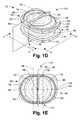
- FIG. 1Ais a plan view of an intervertebral prosthesis endplate of the invention.
- FIG. 1Bis an anterior elevational view of an intervertebral prosthesis incorporating a prosthesis endplate of the invention taken in the direction 1 B- 1 B in FIG. 1A .
- FIG. 1Cis a lateral elevational view of the prosthesis of FIG. 1B , taken in the direction 1 C- 1 C in FIG. 1A .
- FIG. 1Dis a perspective view of another embodiment of an intervertebral prosthesis incorporating a prosthesis endplate of the invention.
- FIG. 1Eis a plan view of the prosthesis of FIG. 1D .
- FIG. 1Fis an anterior elevational view of the prosthesis of FIG. 1D , taken in the direction 1 F- 1 F in FIG. 1D .
- FIG. 1Gis a lateral elevational view of the prosthesis of FIG. 1D , taken in the direction 1 F- 1 F in FIG. 1D .
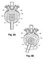
- FIG. 2Ais a superior view of an embodiment of a bone rasp of the invention positioned in an intervertebral space after excision of a central portion of the annulus fibrosus for preparation of a central portion of a recess or seat in the lower or caudal end of the superior vertebra (not shown).
- FIG. 2Bshows the angular reciprocating motion of the rasp of FIG. 2A in preparing the recess in the superior vertebra.
- FIG. 2Cshows a subsequent step in the preparation of a recess in the superior vertebra wherein a second bone rasp having teeth configured to form the peripheral portion of the recess has been inserted into the intervertebral space.
- FIG. 2Dshows the angular reciprocating motion of the rasp of FIG. 2C in preparing the peripheral portion of the recess in the superior vertebra.
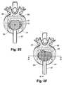
- FIG. 2Eshows an alternate embodiment of a bone rasp for preparing a recess in a vertebral body wherein teeth are arranged and configured to prepare the central and peripheral regions of the recess.
- FIG. 2Fshows another embodiment of the bone rasp for preparing a recess in a vertebral body wherein the teeth are arranged on a generally planar base and have different lengths for forming the shape of the recess, as seen more particularly in the cross-sections of FIGS. 2G and 2H .
- FIG. 2Gshows a cross-section of the bone rasp of FIG. 2F , taken along the line 2 G- 2 G.
- FIG. 2Hshows a cross-section of the bone rasp of FIG. 2F , taken along the line 2 H- 2 H.
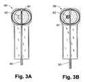
- FIG. 3Ais a plan view of a groove-cutting instrument used to cut a groove within the vertebral body to receive a fin of a prosthesis endplate according to the invention, wherein the cutting element of the instrument is in cutting position.
- FIG. 3Bis a plan view of the groove cutter of FIG. 3A wherein the cutting element is retracted into a recess for insertion of the instrument into an intervertebral space.
- FIG. 3Cis a perspective view of the groove cutter of FIGS. 3A and 3B .
- An intervertebral prosthesis designed to replace a degenerated, damaged, or otherwise defective natural intervertebral disc, with retention of at least some of the function of the natural disctypically incorporates a pair of endplates designed for firm fixation to the adjacent vertebrae of human spinal motion segment, together with some structure separating the endplates and allowing for at least some relative motion therebetween.
- the minimum contact surface area between these prosthesis endplates and the vertebral bone that is required to prevent subsidenceis considered to be approximately 6.5 cm 2 for a person with normal bone density.
- a disc prosthesis endplate having a surface contour (convex) that matches, at least approximately, the generally concave end surface of the adjacent vertebral body that it contactsmay be expected to provide a larger endplate-vertebra contact area than a prosthesis endplate with, e.g., a flat, contact surface, thereby achieving a larger surface contact area with corresponding better post-operative stability.
- a prosthesis endplate with, e.g., a flat, contact surfacethereby achieving a larger surface contact area with corresponding better post-operative stability.
- an endplate for an intervertebral prosthesishas a generally planar base plate, a first elevated region within the periphery of the base plate, and a second elevated region within the planform of the first elevated region.
- the first elevated regionhas an antero-posterior dimension at a median antero-posterior plane and a transverse (or medial-lateral) dimension. These dimensions are made to be unequal, in order to provide for resistance to torsional movement between the endplate and adjacent Vertebral body.
- the transverse dimension of a lumbar vertebral bodyis greater than its antero-posterior dimension
- the first elevated regionwill have a transverse (or medial-lateral) dimension greater than its antero-posterior dimension.
- the first elevated regioncan be described as elongated in a lateral direction.
- the first elevated regionwill be symmetrical about the median antero-posterior plane of the endplate.
- the lateral side portions of the first elevated regionare defined in one embodiment by arcs that terminate in sagittal planes of the endplate and are symmetrical about a coronal plane of the endplate.
- the lateral side portions of the first elevated regionare defined by circular arcs that are centered on points lying in sagittal planes of the endplate.
- the second elevated regionhas a generally dome-shaped surface, and its planform may be a complete circle or may be somewhat truncated at either or both of the anterior or posterior margins.
- the laterally opposite side portions of the second or upper elevated regionare defined by circular arcs having a common center located in the median plane of the endplate.
- This common centermay be located at any position along the median plane that is permitted by the overall size of the second elevated region. In one embodiment of the invention the common center may be located at the centroid of the first elevated region.
- the vertebra-contacting surfacemay also be provided with a generally central antero-posterior fin or keel located on the median plane, to provide additional stability against torsional displacement of the prosthesis with respect to the vertebral body and/or expulsion or extrusion of the prosthesis from the intervertebral space.
- the endplatemay be constructed from any material conventionally used for intervertebral prostheses, e.g., stainless steel, titanium, and the like. It may be manufactured by any conventional process for forming such structures, e.g., by machining, assembling from component parts by welding, or the like.
- the vertebra-contacting surface defined by the base plate and elevated regions of the intervertebral prosthesis endplate of the inventionprovides an approximation to the shape of the natural concave surface of the end of the vertebral body, thus providing, in itself, for greater post-implantation stability of the prosthesis.
- this seat for the prosthesis endplatecan be prepared with a relatively small excavation of the vertebral bone, especially when prepared by the implantation method of the invention described more fully below.
- the inventionalso comprises a method for forming a concave seat in the end of a vertebral body to receive an intervertebral prosthesis endplate of the invention, as well as tools for conveniently and accurately forming such a concave seat.
- the surgical siteis exposed by a conventional anterior approach.
- At least a central and anterior portion of the degenerated intervertebral discis excised, according to the condition of the disc and the surgical exigencies.
- Appropriate distraction of the adjacent vertebraeis performed to provide suitable access to the implantation site.
- a bone rasphaving a central guide post, or pivot, and a head appropriately sized to form the recessed seat and carrying an array of rasp teeth that will form the seat is then inserted into the intervertebral space.
- the central pivot postis then inserted into a corresponding hole in the vertebral endplate made either by using a guide post having a bone-piercing pointed end or by predrilling a guide hole, and the rasp head is oscillated about the guide post in a transverse plane by an anteriorly extending handle to abrade the vertebral body endplate to form the seat for the prosthesis endplate.
- the bone-abrading teeth on the rasp headshould be arranged in a planform and be graded in length in various regions of the planform to form a seat generally complementary to the contour of the vertebra-contacting surface of the prosthesis endplate.
- a bone rasp suitable for preparing a seat for an embodiment of the endplate that has a transverse dimension greater than an antero-posterior dimensionwill generally also have a tooth array having a planform with a greater medial-lateral dimension that antero-posterior dimension and a shape that will form a seat complementary to the prosthesis endplate.
- such an array of teethwill include a circular central region around the guide post with the height of the teeth being symmetrically reduced with distance from the guide post, in order to form the central circular dome-shaped region of the recess.
- the array of teethwill also typically include a lateral region, located radially and laterally outside of the central circular region, which is laterally symmetrical about a central pane of the rasp head and has a planform that will produce a laterally elongated recess complementary to the first elevated region of the prosthesis endplate.
- the laterally outermost teethwill be positioned, and their length will be defined and gradated, to form the lateral portion of the laterally elongated portion of the recess or endplate seat, i.e., the lateral teeth will be shorter than those that form the central domed region.
- these outermost teethwill evidently describe a circular arc at each lateral extremity whose angular extent is determined by the angle through which the rasp head is oscillated as well as the angular sector of the rasp head covered by the array of teeth.
- the planform of the lateral regionwill be designed to form the anterior and posterior limits of the elongated recess when the rasp head is oscillated to its maximum excursion from its initially centrally aligned position.
- the dimensions of this inward portion of the lateral region of the array of teethmay be chosen to form any particularly selected shape for the portion of the elongated recess connecting the outermost circular arcs.
- the laterally inward portions of the planform of the tooth arraywill be designed to produce generally straight laterally-extending anterior and posterior walls wall connecting the lateral terminal arcs of the elongated recess.
- the rasp headwill be oscillated through an arc having an excursion of 10-15 degrees on each side of its initial central position, thereby creating an elongated recess having laterally terminal circular arcs, centered on the pivot point, of about 20-30 degrees. Other sizes of arcs can be selected for appropriate reasons. If the lateral regions of the tooth array are also symmetrical about a transverse plane, it is evident that the pivot point will be located at a centroid of the elongated recess.
- the inventionincludes a method and apparatus for forming an antero-posterior medial groove in a vertebral endplate to receive an antero-posterior medial fin or keel of a prosthesis endplate.
- fins or keelshave been used as stabilizing features of intervertebral prostheses
- formation of a groove in the vertebral body to receive such a finhas ordinarily involved forming an aperture in at least the anterior rim of strong cortical bone surrounding the vertebral body.
- a groove for receiving a fin of an intervertebral prosthesisis cut only in the interior portion of the end of the vertebral body, sparing the rim of cortical bone.
- the groove-making toolincludes a retractable or stowable cutter that is reciprocated along an antero-posterior medial channel by means of an operating shaft extending anteriorly to be operated by the surgeon.
- the cutteris retracted or stowed in a protective element when the tool is inserted into the intervertebral space, thus bypassing the cortical bone.
- the cutteris deployed and reciprocated to for a groove that accepts the fin of the prosthesis endplate, but does not extend through the cortical bone rim of the vertebra. Accordingly, the intact cortical bone rim provides superior resistance to expulsion of the prosthesis.
- an intervertebral prosthesis using one or both endplates according to the invention, together with the formation of a corresponding seat in the vertebral bodyprovides for a highly congruent contact between the endplate and the vertebral body, thereby providing a superior stability of the prosthesis against failure modes such as subsidence, migration, and expulsion.
- the surgical method and tools for forming the seat for the prosthesis endplatecontribute to the simplicity of the implantation procedure.
- the intervertebral prosthesis endplate of the inventionis suitable for use with any such prosthesis employing any appropriate core structure or mechanism to allow restored physiological motion of the spinal motion segment. It is particularly adaptable to an intervertebral disc prosthesis wherein the core component is an elastomeric element that allows normal physiological motion.
- FIGS. 1A-1Cillustrate a prosthesis endplate of the invention and its use in an intervertebral prosthesis having an elastomeric core element.
- the prosthesishas an elastomeric core element 100 and a pair of endplates 110 that are designed to contact the vertebral bodies of adjacent vertebrae in a human spinal motion segment.
- the prosthesis 120has an anterior end 122 and a posterior end 124 as implanted in a spinal motion segment.
- Each of the endplates 110comprises a base plate 112 , a first elevated region 102 , a second elevated region 103 and a medial fin 104 .
- the porous coatinge.g., of metallic beads, with which it is ordinarily provided in order to promote bone growth after implantation.
- the base plate 112has a peripheral rim 101 , generally sized and configured to fit within the dimensions of an intervertebral space of a spinal motion segment.
- a first or lower elevated region or dome 102is supported on the base plate 112 and has a wall or boundary 114 , spaced radially inward from peripheral rim 101 .
- the wall 114has lateral extremities 116 generally in the shape of curved arcs 117 that terminate in sagittal planes 134 . These arcs 117 are generally symmetrical about a coronal plane 136 of the endplate 110 .
- the vertical profile of the first elevated region 102may have varied shapes. For example, it may have a profile including a low wall and a generally planar elevated surface with a smooth transition therebetween.
- the profile of the first elevated region 102may have a continuous constant or varied curvature from one extremity of the planform boundary 114 to the other in a lateral or antero-posterior orientation, with the evident proviso that such curvatures must be chosen to meet the planform boundary 114 , which has a lateral dimension different from and typically greater than an antero-posterior dimension, as discussed above.
- a second elevated region or dome 103is supported on the first elevated region 102 .
- the second elevated region 103is bounded on its lateral portions by circular arcs 133 centered about a center point or axis 131 located on a median plane 132 of the endplate 110 .
- the center point or axis 131may also be located on the coronal plane 136 , but does not have to be so positioned.
- the second elevated region 103may have a generally circular planform 130 , as shown.
- the second elevated region 103typically has a vertical profile having a uniform curvature to provide a circular dome shape, as best seen in FIGS. 1B and 1C .
- the planform and curvatures of the second elevated region 103may also be varied, within the parameters defined above, as discussed above for the first elevated region 102 .
- the endplate 110is provided with a medial fin 104 , which is an optional element which may be included to provide for greater torsional stability of the prosthesis after implantation.
- FIGS. 1D-1Gillustrate another embodiment of the prosthesis endplate of the invention as used in a prosthesis 170 having an elastomeric core element.
- FIG. 1Dillustrates a perspective view of such a prosthesis
- FIGS. 1E , 1 F, and 1 Gillustrate plan, anterior elevational, and lateral elevational views, respectively.
- the illustrated prosthesis 170includes an elastomeric core 150 and two endplates 160 .
- the prosthesis 170has an anterior end 172 and a posterior end 174 as implanted in a spinal motion segment.
- the endplate 160comprises a base plate 162 , a first elevated region 152 , a second elevated region 153 and a medial fin 154 .
- the porous coatinge.g., of metallic beads, with which it is ordinarily provided in order to promote bone growth after implantation.
- the base plate 162has a peripheral rim 151 , generally sized and configured to fit within the dimensions of an intervertebral space of a spinal motion segment.
- a first or lower elevated region or dome 152is supported on the base plate 162 and has a wall or boundary 164 , spaced radially inward from peripheral rim 151 .
- the wall 164has lateral extremities 166 generally in the shape of circular arcs termining at sagittal planes 184 .
- the vertical profile of the first elevated region 152may have varied shapes. For example, it may have a profile including a low wall and a generally planar elevated surface with a smooth transition therebetween.
- the profile of the first elevated region 152may have a continuous constant or varied curvature from one extremity of the planform boundary 164 to the other in a lateral or antero-posterior orientation, with the evident proviso that such curvatures must be chosen to meet the planform boundary 164 , which has a lateral dimension greater than an antero-posterior dimension, as discussed above.
- a second elevated region or dome 153is supported on the first elevated region 152 .
- the second elevated region 153has a generally circular planform 180 , centered on a center or centroid 168 of the first elevated region 152 , with a uniform curvature to provide a circular dome shape.
- the planform and curvatures of the second elevated region 153may also be varied, as discussed above for the first elevated region 152 .
- the endplate 160is provided with a medial fin 154 , which is an optional element which may be included to provide for greater torsional stability.
- the first elevated region and second elevated regionare generally symmetrical with respect to a median plane 182 , illustrated schematically in FIG. 1D and in FIGS. 1E and 1F .
- the circular arc shape of the lateral extremities 166 of the wall or boundary 164allows for ease of construction of a seat for the endplate 160 in the vertebral body, as discussed more fully below.
- the medial-lateral dimension of the first elevated region 152is made greater than its antero-posterior dimension in order to provide stability against the possibility of torsional displacement of the prosthesis with respect to the vertebral body.
- the second elevated region 153typically has a generally circular planform in order to conform to the generally concave shape of the end of the vertebral body.
- the curvature of the second elevated region 153may be varied substantially to conform to varying curvatures of the vertebral end structures, which may depend on the level of the disc being replaced and the size of the patient.
- a general dome shapeprovides for forming a seat for the endplate 160 in an adjacent vertebral body while minimizing the amount of vertebral bone that has to be removed.
- the second elevated region 153may also have any shape symmetrical with respect to median plane 182 , as described above for the first elevated region 152 .
- an endplate for an intervertebral prosthesisparticularly when compared with an endplate having a flat or single domed endplate.
- a flat surfaceevidently can provide limited mechanical stability against shear or translational motion of the prosthesis with respect to the vertebral body.
- a single domehaving similar anterior-posterior and medial-lateral dimensions, while it enhances prosthetic stability in shear or simple translation, remains limited in its ability to prevent rotation of the endplate with respect to the vertebral body.
- the inventive designby having two elevated regions, or domes, at least one of which has different medial-lateral and antero-posterior dimensions, provides for enhanced stability in both translation and also in rotation.
- the relatively simple shapes of the elevated regionswhich are adapted to the relatively simple and straightforward procedures and tools for formation of a complementary seat in the vertebral body, provide evident advantages over more complex shapes that could be devised to provide similar stability and would require complex surgical procedures for preparation and implantation.
- FIGS. 2A-2Hshow the bone rasp tools and apparatus used to prepare the recess or seat for receiving the endplate of the invention.
- FIG. 1Ashows an embodiment of a bone rasp tool 201 having a rasp head 202 positioned within an intervertebral space between a lower, or caudal vertebra 206 of a spinal motion segment and the superior or cephalad vertebra (not shown) of the spinal motion segment.
- the central portion of the intervertebral dischas been excised leaving a residual portion 200 of the annulus fibrosus.
- the bone rasp head 202has a central elevated region 210 having teeth 212 arranged to form the central portion of a recess or seat for receiving a prosthesis endplate of the invention.
- the rasphas a central projection or post to serve as a pivot about which the rasp head 202 can be moved in a reciprocating angular motion as indicated in FIG. 2B .
- the peripheral portion 214 of the rasp head 202 in this embodimentis devoid of teeth. Accordingly, this embodiment of the bone rasp is used in a first step to prepare the central region of the recess.
- FIG. 2Cshows a second embodiment of a bone asp having a rasp head 203 positioned within a surgically prepared intervertebral space for forming the peripheral region of the recess.
- the central region 220is devoid of teeth while the peripheral region 222 is provided with teeth 224 for preparing the peripheral region of the recess by angular reciprocating motion as shown in FIG. 2D .
- FIG. 2Eshows an embodiment of the bone rasp having a head 230 wherein both the central region 232 and the peripheral region 234 are provided with teeth 236 for preparing both the central portion and peripheral portions of the recess at the same time.
- FIG. 2Fshows another embodiment of the bone rasp having a head 240 positioned with in a surgically prepared intervertebral space.
- the head 240is provided with teeth 242 of differing lengths in differing regions of the head 240 , as illustrated in the cross sections FIGS. 2G and 2H , for preparing the central and peripheral regions of the recess at the same time.
- FIGS. 3A-3Cillustrate a groove-cutting tool that can be used to prepare the anterior-posterior groove to receive a prosthesis fin, e.g., the fin 104 .
- This tool 300is inserted into the disc cavity after the various rasps have been used and employs a side-cutting edge 301 to prepare a groove on both the superior and inferior surfaces.
- the tool 300is introduced with the cutting edge 301 rotated such it does not protrude above the top surface but rather lies flat within the recess 302 , as shown in FIG. 3B .
- the toolcan be provided with a center guidepost 310 , as shown in FIG.
- 3Cwhich serves both to position the groove-cutting tool within the intervertebral space and to stow the cutter in a place where it will not damage bone or other tissue when the tool 300 is inserted.
- the shaft 303is rotated a quarter turn and the edge cutter 301 is exposed.
- the shaft 303is then reciprocated causing the edge cutter 301 to prepare the appropriate slot in the vertebra.
- the inferior vertebrais prepared in a similar fashion.
- An alternate designprovides for edge cutters on both superior and inferior surfaces of the tool so that both slots are prepared in a single operation.
Landscapes
- Health & Medical Sciences (AREA)
- Engineering & Computer Science (AREA)
- Biomedical Technology (AREA)
- Life Sciences & Earth Sciences (AREA)
- Orthopedic Medicine & Surgery (AREA)
- Animal Behavior & Ethology (AREA)
- Veterinary Medicine (AREA)
- Oral & Maxillofacial Surgery (AREA)
- Public Health (AREA)
- Heart & Thoracic Surgery (AREA)
- General Health & Medical Sciences (AREA)
- Surgery (AREA)
- Transplantation (AREA)
- Neurology (AREA)
- Cardiology (AREA)
- Vascular Medicine (AREA)
- Molecular Biology (AREA)
- Medical Informatics (AREA)
- Nuclear Medicine, Radiotherapy & Molecular Imaging (AREA)
- Dentistry (AREA)
- Physical Education & Sports Medicine (AREA)
- Prostheses (AREA)
Abstract
Description
Claims (25)
Priority Applications (2)
| Application Number | Priority Date | Filing Date | Title |
|---|---|---|---|
| US11/862,012US9011542B2 (en) | 2006-09-26 | 2007-09-26 | Intervertebral prosthesis endplate having double dome and surgical tools for implanting same |
| US14/689,007US9642631B2 (en) | 2006-09-26 | 2015-04-16 | Intervertebral prosthesis endplate having double dome and surgical tools for implanting same |
Applications Claiming Priority (3)
| Application Number | Priority Date | Filing Date | Title |
|---|---|---|---|
| US84710306P | 2006-09-26 | 2006-09-26 | |
| US84735906P | 2006-09-27 | 2006-09-27 | |
| US11/862,012US9011542B2 (en) | 2006-09-26 | 2007-09-26 | Intervertebral prosthesis endplate having double dome and surgical tools for implanting same |
Related Child Applications (1)
| Application Number | Title | Priority Date | Filing Date |
|---|---|---|---|
| US14/689,007DivisionUS9642631B2 (en) | 2006-09-26 | 2015-04-16 | Intervertebral prosthesis endplate having double dome and surgical tools for implanting same |
Publications (2)
| Publication Number | Publication Date |
|---|---|
| US20080077243A1 US20080077243A1 (en) | 2008-03-27 |
| US9011542B2true US9011542B2 (en) | 2015-04-21 |
Family
ID=38961227
Family Applications (2)
| Application Number | Title | Priority Date | Filing Date |
|---|---|---|---|
| US11/862,012Active2032-04-08US9011542B2 (en) | 2006-09-26 | 2007-09-26 | Intervertebral prosthesis endplate having double dome and surgical tools for implanting same |
| US14/689,007Active2027-12-09US9642631B2 (en) | 2006-09-26 | 2015-04-16 | Intervertebral prosthesis endplate having double dome and surgical tools for implanting same |
Family Applications After (1)
| Application Number | Title | Priority Date | Filing Date |
|---|---|---|---|
| US14/689,007Active2027-12-09US9642631B2 (en) | 2006-09-26 | 2015-04-16 | Intervertebral prosthesis endplate having double dome and surgical tools for implanting same |
Country Status (6)
| Country | Link |
|---|---|
| US (2) | US9011542B2 (en) |
| EP (1) | EP2076217B1 (en) |
| AU (1) | AU2007300122A1 (en) |
| CA (1) | CA2664640A1 (en) |
| ES (1) | ES2542691T3 (en) |
| WO (1) | WO2008039850A2 (en) |
Cited By (3)
| Publication number | Priority date | Publication date | Assignee | Title |
|---|---|---|---|---|
| US20160220285A1 (en)* | 2013-07-01 | 2016-08-04 | Biospine Implants | Dynamic intervertebral stabilisation device |
| US10561504B2 (en) | 2016-01-19 | 2020-02-18 | K2M, Inc. | Surgical instrument and methods of use thereof |
| US20240065845A1 (en)* | 2020-12-22 | 2024-02-29 | Healthhub Co.,Ltd. | Cervical artificial disc and method of constructing the same |
Families Citing this family (5)
| Publication number | Priority date | Publication date | Assignee | Title |
|---|---|---|---|---|
| US20080071379A1 (en)* | 2006-05-10 | 2008-03-20 | Mark Rydell | Intervertebral disc replacement |
| US20080154378A1 (en)* | 2006-12-22 | 2008-06-26 | Warsaw Orthopedic, Inc. | Bone implant having engineered surfaces |
| US8470045B2 (en)* | 2008-05-05 | 2013-06-25 | K2M, Inc. | Endplate for an intervertebral prosthesis and prosthesis incorporating the same |
| US9220603B2 (en)* | 2008-07-02 | 2015-12-29 | Simplify Medical, Inc. | Limited motion prosthetic intervertebral disc |
| US9168138B2 (en) | 2009-12-09 | 2015-10-27 | DePuy Synthes Products, Inc. | Aspirating implants and method of bony regeneration |
Citations (104)
| Publication number | Priority date | Publication date | Assignee | Title |
|---|---|---|---|---|
| US3867728A (en) | 1971-12-30 | 1975-02-25 | Cutter Lab | Prosthesis for spinal repair |
| US3875595A (en) | 1974-04-15 | 1975-04-08 | Edward C Froning | Intervertebral disc prosthesis and instruments for locating same |
| GB1496804A (en) | 1975-09-09 | 1978-01-05 | Wolf Gmbh Richard | Supported laryngoscopes |
| GB1589192A (en) | 1978-01-11 | 1981-05-07 | Linder G | Adjustable frame assembly for supporting a surgical tray |
| US4349921A (en) | 1980-06-13 | 1982-09-21 | Kuntz J David | Intervertebral disc prosthesis |
| US4759769A (en) | 1987-02-12 | 1988-07-26 | Health & Research Services Inc. | Artificial spinal disc |
| US4759766A (en) | 1984-09-04 | 1988-07-26 | Humboldt-Universitaet Zu Berlin | Intervertebral disc endoprosthesis |
| US4772287A (en) | 1987-08-20 | 1988-09-20 | Cedar Surgical, Inc. | Prosthetic disc and method of implanting |
| WO1989003663A1 (en) | 1987-10-29 | 1989-05-05 | Atos Medical Ab | Joint prosthesis |
| US4863477A (en) | 1987-05-12 | 1989-09-05 | Monson Gary L | Synthetic intervertebral disc prosthesis |
| US4911718A (en) | 1988-06-10 | 1990-03-27 | University Of Medicine & Dentistry Of N.J. | Functional and biocompatible intervertebral disc spacer |
| US4932969A (en) | 1987-01-08 | 1990-06-12 | Sulzer Brothers Limited | Joint endoprosthesis |
| US4946378A (en) | 1987-11-24 | 1990-08-07 | Asahi Kogaku Kogyo Kabushiki Kaisha | Artificial intervertebral disc |
| WO1990011740A1 (en) | 1989-04-08 | 1990-10-18 | Robert Bosch Gmbh | Artificial spinal disc |
| US5047055A (en) | 1990-12-21 | 1991-09-10 | Pfizer Hospital Products Group, Inc. | Hydrogel intervertebral disc nucleus |
| US5071437A (en) | 1989-02-15 | 1991-12-10 | Acromed Corporation | Artificial disc |
| US5123926A (en) | 1991-02-22 | 1992-06-23 | Madhavan Pisharodi | Artificial spinal prosthesis |
| US5171281A (en) | 1988-08-18 | 1992-12-15 | University Of Medicine & Dentistry Of New Jersey | Functional and biocompatible intervertebral disc spacer containing elastomeric material of varying hardness |
| US5190547A (en) | 1992-05-15 | 1993-03-02 | Midas Rex Pneumatic Tools, Inc. | Replicator for resecting bone to match a pattern |
| US5192326A (en) | 1990-12-21 | 1993-03-09 | Pfizer Hospital Products Group, Inc. | Hydrogel bead intervertebral disc nucleus |
| US5258031A (en) | 1992-01-06 | 1993-11-02 | Danek Medical | Intervertebral disk arthroplasty |
| US5306309A (en) | 1992-05-04 | 1994-04-26 | Calcitek, Inc. | Spinal disk implant and implantation kit |
| US5306308A (en) | 1989-10-23 | 1994-04-26 | Ulrich Gross | Intervertebral implant |
| US5314477A (en) | 1990-03-07 | 1994-05-24 | J.B.S. Limited Company | Prosthesis for intervertebral discs and instruments for implanting it |
| US5320644A (en) | 1991-08-30 | 1994-06-14 | Sulzer Brothers Limited | Intervertebral disk prosthesis |
| US5370697A (en) | 1992-04-21 | 1994-12-06 | Sulzer Medizinaltechnik Ag | Artificial intervertebral disk member |
| US5401269A (en) | 1992-03-13 | 1995-03-28 | Waldemar Link Gmbh & Co. | Intervertebral disc endoprosthesis |
| WO1995019153A1 (en) | 1994-01-18 | 1995-07-20 | Beer John C | Synthetic intervertebral disc |
| DE4219939C2 (en) | 1992-06-18 | 1995-10-19 | Klaus Dipl Ing Radermacher | Device for aligning, positioning and guiding machining tools, machining or measuring devices for machining a bony structure and method for producing this device |
| US5514180A (en) | 1994-01-14 | 1996-05-07 | Heggeness; Michael H. | Prosthetic intervertebral devices |
| US5534028A (en) | 1993-04-20 | 1996-07-09 | Howmedica, Inc. | Hydrogel intervertebral disc nucleus with diminished lateral bulging |
| US5534030A (en) | 1993-02-09 | 1996-07-09 | Acromed Corporation | Spine disc |
| US5545229A (en) | 1988-08-18 | 1996-08-13 | University Of Medicine And Dentistry Of Nj | Functional and biocompatible intervertebral disc spacer containing elastomeric material of varying hardness |
| US5556431A (en) | 1992-03-13 | 1996-09-17 | B+E,Uml U+Ee Ttner-Janz; Karin | Intervertebral disc endoprosthesis |
| US5562738A (en) | 1992-01-06 | 1996-10-08 | Danek Medical, Inc. | Intervertebral disk arthroplasty device |
| US5674294A (en) | 1993-09-14 | 1997-10-07 | Commissariat A L'energie Atomique | Intervertebral disk prosthesis |
| US5674296A (en) | 1994-11-14 | 1997-10-07 | Spinal Dynamics Corporation | Human spinal disc prosthesis |
| US5676702A (en) | 1994-12-16 | 1997-10-14 | Tornier S.A. | Elastic disc prosthesis |
| US5683465A (en) | 1996-03-18 | 1997-11-04 | Shinn; Gary Lee | Artificial intervertebral disk prosthesis |
| US5824094A (en) | 1997-10-17 | 1998-10-20 | Acromed Corporation | Spinal disc |
| US5824093A (en) | 1994-10-17 | 1998-10-20 | Raymedica, Inc. | Prosthetic spinal disc nucleus |
| US5888226A (en) | 1997-11-12 | 1999-03-30 | Rogozinski; Chaim | Intervertebral prosthetic disc |
| US5893889A (en) | 1997-06-20 | 1999-04-13 | Harrington; Michael | Artificial disc |
| WO1999022675A1 (en) | 1997-10-31 | 1999-05-14 | Depuy Acromed, Inc. | Spinal disc prosthesis |
| US5976186A (en) | 1994-09-08 | 1999-11-02 | Stryker Technologies Corporation | Hydrogel intervertebral disc nucleus |
| FR2784291A1 (en) | 1998-10-09 | 2000-04-14 | Dimso Sa | Intervertebral disc prosthesis has connecting pieces with through cells between plates and core |
| US6113637A (en) | 1998-10-22 | 2000-09-05 | Sofamor Danek Holdings, Inc. | Artificial intervertebral joint permitting translational and rotational motion |
| US6136031A (en) | 1998-06-17 | 2000-10-24 | Surgical Dynamics, Inc. | Artificial intervertebral disc |
| US6162252A (en) | 1997-12-12 | 2000-12-19 | Depuy Acromed, Inc. | Artificial spinal disc |
| US6187048B1 (en) | 1994-05-24 | 2001-02-13 | Surgical Dynamics, Inc. | Intervertebral disc implant |
| US6187043B1 (en) | 1987-12-22 | 2001-02-13 | Walter J. Ledergerber | Implantable prosthetic device |
| US6224607B1 (en) | 1999-01-25 | 2001-05-01 | Gary K. Michelson | Instrumentation and method for creating an intervertebral space for receiving an implant |
| US20010016773A1 (en) | 1998-10-15 | 2001-08-23 | Hassan Serhan | Spinal disc |
| US6296664B1 (en) | 1998-06-17 | 2001-10-02 | Surgical Dynamics, Inc. | Artificial intervertebral disc |
| DE20111479U1 (en) | 2001-07-04 | 2001-10-04 | Aesculap AG & Co. KG, 78532 Tuttlingen | Vertebral distractor |
| US20010032017A1 (en) | 1999-12-30 | 2001-10-18 | Alfaro Arthur A. | Intervertebral implants |
| US6368350B1 (en) | 1999-03-11 | 2002-04-09 | Sulzer Spine-Tech Inc. | Intervertebral disc prosthesis and method |
| US6395032B1 (en) | 1998-12-11 | 2002-05-28 | Dimso (Distribution Medicale Du Sud-Ouest) | Intervertebral disc prosthesis with liquid chamber |
| US20020077701A1 (en) | 2000-12-15 | 2002-06-20 | Kuslich Stephen D. | Annulus-reinforcing band |
| US20020077533A1 (en) | 2000-07-12 | 2002-06-20 | Johannes Bieger | Method and device for visualization of positions and orientation of intracorporeally guided instruments during a surgical intervention |
| US6419704B1 (en) | 1999-10-08 | 2002-07-16 | Bret Ferree | Artificial intervertebral disc replacement methods and apparatus |
| US6419706B1 (en) | 1997-12-19 | 2002-07-16 | Sofamor S.N.C. | Partial disc prosthesis |
| US6482234B1 (en) | 2000-04-26 | 2002-11-19 | Pearl Technology Holdings, Llc | Prosthetic spinal disc |
| US6527804B1 (en) | 1998-12-11 | 2003-03-04 | Dimso (Distribution Medicale Du Sud-Quest) | Intervertebral disk prosthesis |
| US20030045939A1 (en) | 2001-08-24 | 2003-03-06 | Simon Casutt | Artificial intervertebral disc |
| US20030074066A1 (en) | 2001-07-16 | 2003-04-17 | Errico Joseph P. | Artificial intervertebral disc having limited rotation using a captured ball and socket joint with a solid ball, a retaining cap, and an interference pin |
| US6579321B1 (en) | 1999-05-17 | 2003-06-17 | Vanderbilt University | Intervertebral disc replacement prosthesis |
| US6579320B1 (en) | 1998-12-11 | 2003-06-17 | Stryker Spine | Intervertebral disc prosthesis with contact blocks |
| US6582467B1 (en) | 2000-10-31 | 2003-06-24 | Vertelink Corporation | Expandable fusion cage |
| US6582468B1 (en) | 1998-12-11 | 2003-06-24 | Spryker Spine | Intervertebral disc prosthesis with compressible body |
| US6582466B1 (en) | 1998-12-11 | 2003-06-24 | Stryker Spine | Intervertebral disc prosthesis with reduced friction |
| US6592624B1 (en) | 1999-11-24 | 2003-07-15 | Depuy Acromed, Inc. | Prosthetic implant element |
| US20030135277A1 (en) | 2001-11-26 | 2003-07-17 | Sdgi Holdings, Inc. | Implantable joint prosthesis and associated instrumentation |
| US6607558B2 (en) | 2001-07-03 | 2003-08-19 | Axiomed Spine Corporation | Artificial disc |
| US20030164172A1 (en) | 2000-06-09 | 2003-09-04 | Chumas Nicole Jane | Method and apparatus for guiding a surgical instrument |
| US6626943B2 (en) | 2001-08-24 | 2003-09-30 | Sulzer Orthopedics Ltd. | Artificial intervertebral disc |
| WO2003090650A1 (en) | 2002-04-25 | 2003-11-06 | Blackstone Medical, Inc. | Artificial intervertebral disc |
| US20030236526A1 (en) | 2002-06-19 | 2003-12-25 | Van Hoeck James E. | Adjustable surgical guide and method of treating vertebral members |
| US20040002711A1 (en) | 2002-06-28 | 2004-01-01 | Berry Bret M. | Instruments and techniques for spinal disc space preparation |
| US6682562B2 (en) | 2000-03-10 | 2004-01-27 | Eurosurgical Sa | Intervertebral disc prosthesis |
| WO2004033516A1 (en) | 2002-10-08 | 2004-04-22 | Ranier Limited | High precision manufacture of polyurethane products such as spinal disc implants having gradual modulus variation |
| US6726720B2 (en) | 2002-03-27 | 2004-04-27 | Depuy Spine, Inc. | Modular disc prosthesis |
| US6733532B1 (en) | 1998-12-11 | 2004-05-11 | Stryker Spine | Intervertebral disc prosthesis with improved mechanical behavior |
| WO2004039291A1 (en) | 2002-10-29 | 2004-05-13 | Spinecore, Inc. | Instrumentation, methods, and features for use in implanting an artificial intervertebral disc |
| US6740118B2 (en) | 2002-01-09 | 2004-05-25 | Sdgi Holdings, Inc. | Intervertebral prosthetic joint |
| US20040103903A1 (en) | 2002-10-18 | 2004-06-03 | Falahee Mark H. | Surgical surface localizing grid |
| US6749635B1 (en) | 1998-09-04 | 2004-06-15 | Sdgi Holdings, Inc. | Peanut spectacle multi discoid thoraco-lumbar disc prosthesis |
| US20040122518A1 (en) | 2002-12-19 | 2004-06-24 | Rhoda William S. | Intervertebral implant |
| US20040122517A1 (en) | 2002-12-10 | 2004-06-24 | Axiomed Spine Corporation | Artificial disc |
| WO2004054453A1 (en) | 2002-12-13 | 2004-07-01 | Aesculap Ag & Co. Kg | Guide device for a surgical machining tool |
| US20040162563A1 (en) | 2000-12-14 | 2004-08-19 | Michelson Gary K. | Spinal interspace shaper |
| US20040167626A1 (en) | 2003-01-23 | 2004-08-26 | Geremakis Perry A. | Expandable artificial disc prosthesis |
| US6793678B2 (en)* | 2002-06-27 | 2004-09-21 | Depuy Acromed, Inc. | Prosthetic intervertebral motion disc having dampening |
| US20040193273A1 (en) | 2003-03-31 | 2004-09-30 | Shih-Shing Huang | Vividly simulated prosthetic intervertebral disc |
| US20040215197A1 (en) | 2003-04-24 | 2004-10-28 | Smith Maurice M. | Minimally invasive instruments and methods for preparing vertebral endplates |
| US20040249462A1 (en) | 2003-06-06 | 2004-12-09 | Shih-Shing Huang | Artificial intervertebral disc flexibly oriented by spring-reinforced bellows |
| US20040267367A1 (en) | 2003-06-30 | 2004-12-30 | Depuy Acromed, Inc | Intervertebral implant with conformable endplate |
| WO2005007041A1 (en) | 2003-07-22 | 2005-01-27 | Synthes Gmbh | Intervertebral implant comprising temporary blocking means |
| US20050027300A1 (en) | 2003-03-31 | 2005-02-03 | Depuy Spine, Inc. | Method and apparatus for artificial disc insertion |
| US20050131544A1 (en) | 2003-12-10 | 2005-06-16 | Axiomed Spine Corporation | Method and apparatus for replacing a damaged spinal disc |
| WO2005072660A1 (en) | 2004-01-27 | 2005-08-11 | Sdgi Holdings, Inc. | Hybrid intervertebral disc system |
| US20050273111A1 (en) | 1999-10-08 | 2005-12-08 | Ferree Bret A | Methods and apparatus for intervertebral disc removal and endplate preparation |
| US20060265075A1 (en) | 2003-04-14 | 2006-11-23 | Daniel Baumgartner | Intervertebral implant |
| US20060276900A1 (en) | 2005-06-01 | 2006-12-07 | Carpenter Clyde T | Anatomic total disc replacement |
Family Cites Families (2)
| Publication number | Priority date | Publication date | Assignee | Title |
|---|---|---|---|---|
| US5548642A (en)* | 1994-12-23 | 1996-08-20 | At&T Corp. | Optimization of adaptive filter tap settings for subband acoustic echo cancelers in teleconferencing |
| US6083228A (en)* | 1998-06-09 | 2000-07-04 | Michelson; Gary K. | Device and method for preparing a space between adjacent vertebrae to receive an insert |
- 2007
- 2007-09-26WOPCT/US2007/079557patent/WO2008039850A2/enactiveApplication Filing
- 2007-09-26USUS11/862,012patent/US9011542B2/enactiveActive
- 2007-09-26ESES07843237.4Tpatent/ES2542691T3/enactiveActive
- 2007-09-26AUAU2007300122Apatent/AU2007300122A1/ennot_activeAbandoned
- 2007-09-26CACA 2664640patent/CA2664640A1/ennot_activeAbandoned
- 2007-09-26EPEP20070843237patent/EP2076217B1/ennot_activeNot-in-force
- 2015
- 2015-04-16USUS14/689,007patent/US9642631B2/enactiveActive
Patent Citations (127)
| Publication number | Priority date | Publication date | Assignee | Title |
|---|---|---|---|---|
| US3867728A (en) | 1971-12-30 | 1975-02-25 | Cutter Lab | Prosthesis for spinal repair |
| US3875595A (en) | 1974-04-15 | 1975-04-08 | Edward C Froning | Intervertebral disc prosthesis and instruments for locating same |
| GB1496804A (en) | 1975-09-09 | 1978-01-05 | Wolf Gmbh Richard | Supported laryngoscopes |
| GB1589192A (en) | 1978-01-11 | 1981-05-07 | Linder G | Adjustable frame assembly for supporting a surgical tray |
| US4349921A (en) | 1980-06-13 | 1982-09-21 | Kuntz J David | Intervertebral disc prosthesis |
| US4759766A (en) | 1984-09-04 | 1988-07-26 | Humboldt-Universitaet Zu Berlin | Intervertebral disc endoprosthesis |
| US4932969A (en) | 1987-01-08 | 1990-06-12 | Sulzer Brothers Limited | Joint endoprosthesis |
| US4759769A (en) | 1987-02-12 | 1988-07-26 | Health & Research Services Inc. | Artificial spinal disc |
| US4863477A (en) | 1987-05-12 | 1989-09-05 | Monson Gary L | Synthetic intervertebral disc prosthesis |
| US4772287A (en) | 1987-08-20 | 1988-09-20 | Cedar Surgical, Inc. | Prosthetic disc and method of implanting |
| US4904260A (en) | 1987-08-20 | 1990-02-27 | Cedar Surgical, Inc. | Prosthetic disc containing therapeutic material |
| WO1989003663A1 (en) | 1987-10-29 | 1989-05-05 | Atos Medical Ab | Joint prosthesis |
| US4946378A (en) | 1987-11-24 | 1990-08-07 | Asahi Kogaku Kogyo Kabushiki Kaisha | Artificial intervertebral disc |
| US6187043B1 (en) | 1987-12-22 | 2001-02-13 | Walter J. Ledergerber | Implantable prosthetic device |
| US4911718A (en) | 1988-06-10 | 1990-03-27 | University Of Medicine & Dentistry Of N.J. | Functional and biocompatible intervertebral disc spacer |
| US5171281A (en) | 1988-08-18 | 1992-12-15 | University Of Medicine & Dentistry Of New Jersey | Functional and biocompatible intervertebral disc spacer containing elastomeric material of varying hardness |
| US5545229A (en) | 1988-08-18 | 1996-08-13 | University Of Medicine And Dentistry Of Nj | Functional and biocompatible intervertebral disc spacer containing elastomeric material of varying hardness |
| US5071437A (en) | 1989-02-15 | 1991-12-10 | Acromed Corporation | Artificial disc |
| WO1990011740A1 (en) | 1989-04-08 | 1990-10-18 | Robert Bosch Gmbh | Artificial spinal disc |
| US5306308A (en) | 1989-10-23 | 1994-04-26 | Ulrich Gross | Intervertebral implant |
| US5314477A (en) | 1990-03-07 | 1994-05-24 | J.B.S. Limited Company | Prosthesis for intervertebral discs and instruments for implanting it |
| US5192326A (en) | 1990-12-21 | 1993-03-09 | Pfizer Hospital Products Group, Inc. | Hydrogel bead intervertebral disc nucleus |
| US5047055A (en) | 1990-12-21 | 1991-09-10 | Pfizer Hospital Products Group, Inc. | Hydrogel intervertebral disc nucleus |
| US5123926A (en) | 1991-02-22 | 1992-06-23 | Madhavan Pisharodi | Artificial spinal prosthesis |
| US5320644A (en) | 1991-08-30 | 1994-06-14 | Sulzer Brothers Limited | Intervertebral disk prosthesis |
| US5258031A (en) | 1992-01-06 | 1993-11-02 | Danek Medical | Intervertebral disk arthroplasty |
| US5562738A (en) | 1992-01-06 | 1996-10-08 | Danek Medical, Inc. | Intervertebral disk arthroplasty device |
| US5401269A (en) | 1992-03-13 | 1995-03-28 | Waldemar Link Gmbh & Co. | Intervertebral disc endoprosthesis |
| US5556431A (en) | 1992-03-13 | 1996-09-17 | B+E,Uml U+Ee Ttner-Janz; Karin | Intervertebral disc endoprosthesis |
| US5370697A (en) | 1992-04-21 | 1994-12-06 | Sulzer Medizinaltechnik Ag | Artificial intervertebral disk member |
| EP0566810B1 (en) | 1992-04-21 | 1996-08-14 | SULZER Medizinaltechnik AG | Artificial spinal disc |
| US5306309A (en) | 1992-05-04 | 1994-04-26 | Calcitek, Inc. | Spinal disk implant and implantation kit |
| US5190547A (en) | 1992-05-15 | 1993-03-02 | Midas Rex Pneumatic Tools, Inc. | Replicator for resecting bone to match a pattern |
| DE4219939C2 (en) | 1992-06-18 | 1995-10-19 | Klaus Dipl Ing Radermacher | Device for aligning, positioning and guiding machining tools, machining or measuring devices for machining a bony structure and method for producing this device |
| US5534030A (en) | 1993-02-09 | 1996-07-09 | Acromed Corporation | Spine disc |
| US5534028A (en) | 1993-04-20 | 1996-07-09 | Howmedica, Inc. | Hydrogel intervertebral disc nucleus with diminished lateral bulging |
| US5674294A (en) | 1993-09-14 | 1997-10-07 | Commissariat A L'energie Atomique | Intervertebral disk prosthesis |
| EP0642775B1 (en) | 1993-09-14 | 2000-01-12 | Commissariat A L'energie Atomique | Intervertebral disc prosthesis |
| US5514180A (en) | 1994-01-14 | 1996-05-07 | Heggeness; Michael H. | Prosthetic intervertebral devices |
| US5458642A (en) | 1994-01-18 | 1995-10-17 | Beer; John C. | Synthetic intervertebral disc |
| WO1995019153A1 (en) | 1994-01-18 | 1995-07-20 | Beer John C | Synthetic intervertebral disc |
| US6187048B1 (en) | 1994-05-24 | 2001-02-13 | Surgical Dynamics, Inc. | Intervertebral disc implant |
| US5976186A (en) | 1994-09-08 | 1999-11-02 | Stryker Technologies Corporation | Hydrogel intervertebral disc nucleus |
| US5824093A (en) | 1994-10-17 | 1998-10-20 | Raymedica, Inc. | Prosthetic spinal disc nucleus |
| US5865846A (en) | 1994-11-14 | 1999-02-02 | Bryan; Vincent | Human spinal disc prosthesis |
| US6156067A (en) | 1994-11-14 | 2000-12-05 | Spinal Dynamics Corporation | Human spinal disc prosthesis |
| US5674296A (en) | 1994-11-14 | 1997-10-07 | Spinal Dynamics Corporation | Human spinal disc prosthesis |
| US5676702A (en) | 1994-12-16 | 1997-10-14 | Tornier S.A. | Elastic disc prosthesis |
| US5683465A (en) | 1996-03-18 | 1997-11-04 | Shinn; Gary Lee | Artificial intervertebral disk prosthesis |
| US5893889A (en) | 1997-06-20 | 1999-04-13 | Harrington; Michael | Artificial disc |
| US20030100951A1 (en) | 1997-10-17 | 2003-05-29 | Hassan Serhan | Spinal disc |
| US6669732B2 (en) | 1997-10-17 | 2003-12-30 | Depuy Acromed, Inc. | Spinal disc |
| US5824094A (en) | 1997-10-17 | 1998-10-20 | Acromed Corporation | Spinal disc |
| US20020022888A1 (en) | 1997-10-17 | 2002-02-21 | Hassan Serhan | Spinal disc |
| WO1999022675A1 (en) | 1997-10-31 | 1999-05-14 | Depuy Acromed, Inc. | Spinal disc prosthesis |
| US6139579A (en) | 1997-10-31 | 2000-10-31 | Depuy Motech Acromed, Inc. | Spinal disc |
| US6348071B1 (en) | 1997-10-31 | 2002-02-19 | Depuy Acromed, Inc. | Spinal disc |
| US5888226A (en) | 1997-11-12 | 1999-03-30 | Rogozinski; Chaim | Intervertebral prosthetic disc |
| US6162252A (en) | 1997-12-12 | 2000-12-19 | Depuy Acromed, Inc. | Artificial spinal disc |
| US6419706B1 (en) | 1997-12-19 | 2002-07-16 | Sofamor S.N.C. | Partial disc prosthesis |
| US6315797B1 (en) | 1998-06-17 | 2001-11-13 | Surgical Dynamics, Inc. | Artificial intervertebral disc |
| US6656224B2 (en) | 1998-06-17 | 2003-12-02 | Howmedica Osteonics Corp. | Artificial intervertebral disc |
| US20010051829A1 (en) | 1998-06-17 | 2001-12-13 | Middleton Lance M. | Artificial intervertebral disc |
| US6136031A (en) | 1998-06-17 | 2000-10-24 | Surgical Dynamics, Inc. | Artificial intervertebral disc |
| US6296664B1 (en) | 1998-06-17 | 2001-10-02 | Surgical Dynamics, Inc. | Artificial intervertebral disc |
| US6749635B1 (en) | 1998-09-04 | 2004-06-15 | Sdgi Holdings, Inc. | Peanut spectacle multi discoid thoraco-lumbar disc prosthesis |
| FR2784291A1 (en) | 1998-10-09 | 2000-04-14 | Dimso Sa | Intervertebral disc prosthesis has connecting pieces with through cells between plates and core |
| FR2784291B1 (en) | 1998-10-09 | 2001-03-09 | Dimso Sa | HIGH RESISTANCE INTERVERTEBRAL DISC PROSTHESIS |
| US20010016773A1 (en) | 1998-10-15 | 2001-08-23 | Hassan Serhan | Spinal disc |
| US6113637A (en) | 1998-10-22 | 2000-09-05 | Sofamor Danek Holdings, Inc. | Artificial intervertebral joint permitting translational and rotational motion |
| US6733532B1 (en) | 1998-12-11 | 2004-05-11 | Stryker Spine | Intervertebral disc prosthesis with improved mechanical behavior |
| US6395032B1 (en) | 1998-12-11 | 2002-05-28 | Dimso (Distribution Medicale Du Sud-Ouest) | Intervertebral disc prosthesis with liquid chamber |
| US6527804B1 (en) | 1998-12-11 | 2003-03-04 | Dimso (Distribution Medicale Du Sud-Quest) | Intervertebral disk prosthesis |
| US6582468B1 (en) | 1998-12-11 | 2003-06-24 | Spryker Spine | Intervertebral disc prosthesis with compressible body |
| US6582466B1 (en) | 1998-12-11 | 2003-06-24 | Stryker Spine | Intervertebral disc prosthesis with reduced friction |
| US6579320B1 (en) | 1998-12-11 | 2003-06-17 | Stryker Spine | Intervertebral disc prosthesis with contact blocks |
| US6224607B1 (en) | 1999-01-25 | 2001-05-01 | Gary K. Michelson | Instrumentation and method for creating an intervertebral space for receiving an implant |
| US6368350B1 (en) | 1999-03-11 | 2002-04-09 | Sulzer Spine-Tech Inc. | Intervertebral disc prosthesis and method |
| US6579321B1 (en) | 1999-05-17 | 2003-06-17 | Vanderbilt University | Intervertebral disc replacement prosthesis |
| US6419704B1 (en) | 1999-10-08 | 2002-07-16 | Bret Ferree | Artificial intervertebral disc replacement methods and apparatus |
| US20050273111A1 (en) | 1999-10-08 | 2005-12-08 | Ferree Bret A | Methods and apparatus for intervertebral disc removal and endplate preparation |
| US6592624B1 (en) | 1999-11-24 | 2003-07-15 | Depuy Acromed, Inc. | Prosthetic implant element |
| US20010032017A1 (en) | 1999-12-30 | 2001-10-18 | Alfaro Arthur A. | Intervertebral implants |
| US6682562B2 (en) | 2000-03-10 | 2004-01-27 | Eurosurgical Sa | Intervertebral disc prosthesis |
| US6482234B1 (en) | 2000-04-26 | 2002-11-19 | Pearl Technology Holdings, Llc | Prosthetic spinal disc |
| US6533818B1 (en) | 2000-04-26 | 2003-03-18 | Pearl Technology Holdings, Llc | Artificial spinal disc |
| US20030164172A1 (en) | 2000-06-09 | 2003-09-04 | Chumas Nicole Jane | Method and apparatus for guiding a surgical instrument |
| US20020077533A1 (en) | 2000-07-12 | 2002-06-20 | Johannes Bieger | Method and device for visualization of positions and orientation of intracorporeally guided instruments during a surgical intervention |
| US6582467B1 (en) | 2000-10-31 | 2003-06-24 | Vertelink Corporation | Expandable fusion cage |
| US20040162563A1 (en) | 2000-12-14 | 2004-08-19 | Michelson Gary K. | Spinal interspace shaper |
| US20020077701A1 (en) | 2000-12-15 | 2002-06-20 | Kuslich Stephen D. | Annulus-reinforcing band |
| US20030208271A1 (en) | 2001-07-03 | 2003-11-06 | Axiomed Spine Corporation | Artificial disc |
| US6607558B2 (en) | 2001-07-03 | 2003-08-19 | Axiomed Spine Corporation | Artificial disc |
| DE20111479U1 (en) | 2001-07-04 | 2001-10-04 | Aesculap AG & Co. KG, 78532 Tuttlingen | Vertebral distractor |
| US20030074066A1 (en) | 2001-07-16 | 2003-04-17 | Errico Joseph P. | Artificial intervertebral disc having limited rotation using a captured ball and socket joint with a solid ball, a retaining cap, and an interference pin |
| US6645248B2 (en) | 2001-08-24 | 2003-11-11 | Sulzer Orthopedics Ltd. | Artificial intervertebral disc |
| US20030045939A1 (en) | 2001-08-24 | 2003-03-06 | Simon Casutt | Artificial intervertebral disc |
| US6626943B2 (en) | 2001-08-24 | 2003-09-30 | Sulzer Orthopedics Ltd. | Artificial intervertebral disc |
| US20030135277A1 (en) | 2001-11-26 | 2003-07-17 | Sdgi Holdings, Inc. | Implantable joint prosthesis and associated instrumentation |
| US6740118B2 (en) | 2002-01-09 | 2004-05-25 | Sdgi Holdings, Inc. | Intervertebral prosthetic joint |
| US6726720B2 (en) | 2002-03-27 | 2004-04-27 | Depuy Spine, Inc. | Modular disc prosthesis |
| WO2003090650A1 (en) | 2002-04-25 | 2003-11-06 | Blackstone Medical, Inc. | Artificial intervertebral disc |
| US20030236526A1 (en) | 2002-06-19 | 2003-12-25 | Van Hoeck James E. | Adjustable surgical guide and method of treating vertebral members |
| US6793678B2 (en)* | 2002-06-27 | 2004-09-21 | Depuy Acromed, Inc. | Prosthetic intervertebral motion disc having dampening |
| US20040002711A1 (en) | 2002-06-28 | 2004-01-01 | Berry Bret M. | Instruments and techniques for spinal disc space preparation |
| WO2004033516A1 (en) | 2002-10-08 | 2004-04-22 | Ranier Limited | High precision manufacture of polyurethane products such as spinal disc implants having gradual modulus variation |
| US20040103903A1 (en) | 2002-10-18 | 2004-06-03 | Falahee Mark H. | Surgical surface localizing grid |
| WO2004039291A1 (en) | 2002-10-29 | 2004-05-13 | Spinecore, Inc. | Instrumentation, methods, and features for use in implanting an artificial intervertebral disc |
| US7169181B2 (en) | 2002-12-10 | 2007-01-30 | Axiomed Spine Corporation | Artificial disc |
| US20040122517A1 (en) | 2002-12-10 | 2004-06-24 | Axiomed Spine Corporation | Artificial disc |
| WO2004054453A1 (en) | 2002-12-13 | 2004-07-01 | Aesculap Ag & Co. Kg | Guide device for a surgical machining tool |
| US20060079907A1 (en) | 2002-12-13 | 2006-04-13 | Aesculap Ag & Co. Kg | Guide device for a surgical machining tool |
| US20040122518A1 (en) | 2002-12-19 | 2004-06-24 | Rhoda William S. | Intervertebral implant |
| US20040167626A1 (en) | 2003-01-23 | 2004-08-26 | Geremakis Perry A. | Expandable artificial disc prosthesis |
| US20040193273A1 (en) | 2003-03-31 | 2004-09-30 | Shih-Shing Huang | Vividly simulated prosthetic intervertebral disc |
| US20050027300A1 (en) | 2003-03-31 | 2005-02-03 | Depuy Spine, Inc. | Method and apparatus for artificial disc insertion |
| US6893465B2 (en) | 2003-03-31 | 2005-05-17 | Shi, Tain-Yew | Vividly simulated prosthetic intervertebral disc |
| US20060265075A1 (en) | 2003-04-14 | 2006-11-23 | Daniel Baumgartner | Intervertebral implant |
| US20040215197A1 (en) | 2003-04-24 | 2004-10-28 | Smith Maurice M. | Minimally invasive instruments and methods for preparing vertebral endplates |
| US20040249462A1 (en) | 2003-06-06 | 2004-12-09 | Shih-Shing Huang | Artificial intervertebral disc flexibly oriented by spring-reinforced bellows |
| US20040267367A1 (en) | 2003-06-30 | 2004-12-30 | Depuy Acromed, Inc | Intervertebral implant with conformable endplate |
| US20060229724A1 (en) | 2003-07-22 | 2006-10-12 | Beat Lechmann | Intervertebral implant comprising temporary blocking means |
| WO2005007041A1 (en) | 2003-07-22 | 2005-01-27 | Synthes Gmbh | Intervertebral implant comprising temporary blocking means |
| US20050131544A1 (en) | 2003-12-10 | 2005-06-16 | Axiomed Spine Corporation | Method and apparatus for replacing a damaged spinal disc |
| WO2005072660A1 (en) | 2004-01-27 | 2005-08-11 | Sdgi Holdings, Inc. | Hybrid intervertebral disc system |
| US7250060B2 (en) | 2004-01-27 | 2007-07-31 | Sdgi Holdings, Inc. | Hybrid intervertebral disc system |
| US20060276900A1 (en) | 2005-06-01 | 2006-12-07 | Carpenter Clyde T | Anatomic total disc replacement |
Non-Patent Citations (10)
| Title |
|---|
| Closkey RF et al., Spine 18(8): 1011-1015, 1993. |
| Fraser RD et al., Spine J. 2004, 4(6S): 245s-251s. |
| Hawkins MV et al., J. Orthop. Res. 12: 119-127, 1994. |
| Hellier WG et al., Spine 1992, 127(6 Suppl.): Ss86-96. |
| International Search Report and Written Opinion of the International Searching Authority issued May 13, 2008, in International Patent Application No. PCT/US2007/079557. |
| Langrana NA et al.,Spine J. 4 (2004), 245S-251S. |
| McAfee, P. et al., Spine J. 4:48s, 2004. |
| Official Communication dated Mar. 12, 2013, in European Patent Application No. 07 843 237. |
| Official Communication dated Oct. 10, 2011, in European Patent Application No. 07 843 237. |
| Szpalski M, Eur. Spine J. (2000), 11(Suppl.2): S65-84. |
Cited By (4)
| Publication number | Priority date | Publication date | Assignee | Title |
|---|---|---|---|---|
| US20160220285A1 (en)* | 2013-07-01 | 2016-08-04 | Biospine Implants | Dynamic intervertebral stabilisation device |
| US10039575B2 (en)* | 2013-07-01 | 2018-08-07 | Cousin Biotech Sas | Dynamic intervertebral stabilisation device |
| US10561504B2 (en) | 2016-01-19 | 2020-02-18 | K2M, Inc. | Surgical instrument and methods of use thereof |
| US20240065845A1 (en)* | 2020-12-22 | 2024-02-29 | Healthhub Co.,Ltd. | Cervical artificial disc and method of constructing the same |
Also Published As
| Publication number | Publication date |
|---|---|
| WO2008039850A3 (en) | 2008-07-03 |
| AU2007300122A1 (en) | 2008-04-03 |
| EP2076217A2 (en) | 2009-07-08 |
| US20150289888A1 (en) | 2015-10-15 |
| US9642631B2 (en) | 2017-05-09 |
| US20080077243A1 (en) | 2008-03-27 |
| EP2076217B1 (en) | 2015-04-15 |
| ES2542691T3 (en) | 2015-08-10 |
| CA2664640A1 (en) | 2008-04-03 |
| WO2008039850A2 (en) | 2008-04-03 |
Similar Documents
| Publication | Publication Date | Title |
|---|---|---|
| US9642631B2 (en) | Intervertebral prosthesis endplate having double dome and surgical tools for implanting same | |
| US10993813B2 (en) | Prosthetic spinal disc replacement and methods thereof | |
| US20220015927A1 (en) | Intervertebral Disc Implants And Tooling | |
| US8246684B2 (en) | Intervertebral disc and facet joint prosthesis | |
| US9125751B2 (en) | Transforaminal prosthetic spinal disc replacement and methods thereof | |
| US7922766B2 (en) | Method for resurfacing a cervical articular facet | |
| US7766914B2 (en) | Adjustable drill guide | |
| US9179925B2 (en) | Anterior prosthetic spinal disc replacement | |
| US9277930B2 (en) | Intervertebral disc replacement and associated instrumentation | |
| EP3154479B1 (en) | Prosthetic spinal disc replacement |
Legal Events
| Date | Code | Title | Description |
|---|---|---|---|
| AS | Assignment | Owner name:NEXGEN SPINE, INC., NEW JERSEY Free format text:ASSIGNMENT OF ASSIGNORS INTEREST;ASSIGNORS:LEE, CASEY K.;MAKRIS, GEROGE;CLEMOW, ALASTAIR J.T.;AND OTHERS;SIGNING DATES FROM 20071115 TO 20071119;REEL/FRAME:020199/0914 Owner name:NEXGEN SPINE, INC., NEW JERSEY Free format text:ASSIGNMENT OF ASSIGNORS INTEREST;ASSIGNORS:LEE, CASEY K.;MAKRIS, GEROGE;CLEMOW, ALASTAIR J.T.;AND OTHERS;REEL/FRAME:020199/0914;SIGNING DATES FROM 20071115 TO 20071119 | |
| AS | Assignment | Owner name:K2M, INC., VIRGINIA Free format text:ASSIGNMENT OF ASSIGNORS INTEREST;ASSIGNOR:NEXGEN SPINE, INC.;REEL/FRAME:027716/0527 Effective date:20111121 | |
| AS | Assignment | Owner name:SILICON VALLEY BANK, MASSACHUSETTS Free format text:SECURITY INTEREST;ASSIGNORS:K2M, INC.;K2M HOLDING, INC.;K2M UK LIMITED;REEL/FRAME:029489/0327 Effective date:20121029 | |
| STCF | Information on status: patent grant | Free format text:PATENTED CASE | |
| AS | Assignment | Owner name:SILICON VALLEY BANK, AS ADMINISTRATIVE AGENT, CALIFORNIA Free format text:SECOND AMENDMENT TO PATENT SECURITY AGREEMENT;ASSIGNORS:K2M, INC.;K2M HOLDINGS, INC.;K2M UK LIMITED;REEL/FRAME:037091/0221 Effective date:20151029 Owner name:SILICON VALLEY BANK, AS ADMINISTRATIVE AGENT, CALI Free format text:SECOND AMENDMENT TO PATENT SECURITY AGREEMENT;ASSIGNORS:K2M, INC.;K2M HOLDINGS, INC.;K2M UK LIMITED;REEL/FRAME:037091/0221 Effective date:20151029 | |
| AS | Assignment | Owner name:SILICON VALLEY BANK, AS ADMINISTRATIVE AGENT, CALIFORNIA Free format text:THIRD AMENDMENT TO PATENT SECURITY AGREEMENT;ASSIGNORS:K2M, INC.;K2M HOLDINGS, INC.;K2M UK LIMITED;REEL/FRAME:039627/0659 Effective date:20160808 Owner name:SILICON VALLEY BANK, AS ADMINISTRATIVE AGENT, CALI Free format text:THIRD AMENDMENT TO PATENT SECURITY AGREEMENT;ASSIGNORS:K2M, INC.;K2M HOLDINGS, INC.;K2M UK LIMITED;REEL/FRAME:039627/0659 Effective date:20160808 | |
| FEPP | Fee payment procedure | Free format text:ENTITY STATUS SET TO UNDISCOUNTED (ORIGINAL EVENT CODE: BIG.); ENTITY STATUS OF PATENT OWNER: LARGE ENTITY | |
| MAFP | Maintenance fee payment | Free format text:PAYMENT OF MAINTENANCE FEE, 4TH YEAR, LARGE ENTITY (ORIGINAL EVENT CODE: M1551); ENTITY STATUS OF PATENT OWNER: LARGE ENTITY Year of fee payment:4 | |
| AS | Assignment | Owner name:K2M HOLDINGS, INC., VIRGINIA Free format text:RELEASE BY SECURED PARTY;ASSIGNOR:SILICON VALLEY BANK;REEL/FRAME:047496/0001 Effective date:20181109 Owner name:K2M, INC., VIRGINIA Free format text:RELEASE BY SECURED PARTY;ASSIGNOR:SILICON VALLEY BANK;REEL/FRAME:047496/0001 Effective date:20181109 Owner name:K2M UK LIMITED, UNITED KINGDOM Free format text:RELEASE BY SECURED PARTY;ASSIGNOR:SILICON VALLEY BANK;REEL/FRAME:047496/0001 Effective date:20181109 | |
| MAFP | Maintenance fee payment | Free format text:PAYMENT OF MAINTENANCE FEE, 8TH YEAR, LARGE ENTITY (ORIGINAL EVENT CODE: M1552); ENTITY STATUS OF PATENT OWNER: LARGE ENTITY Year of fee payment:8 | |
| AS | Assignment | Owner name:STRYKER CORPORATION, MICHIGAN Free format text:ASSIGNMENT OF ASSIGNORS INTEREST;ASSIGNOR:K2M, INC.;REEL/FRAME:071271/0170 Effective date:20250328 | |
| AS | Assignment | Owner name:VB SPINE US OPCO LLC, DELAWARE Free format text:ASSIGNMENT OF ASSIGNORS INTEREST;ASSIGNOR:STRYKER CORPORATION;REEL/FRAME:071312/0356 Effective date:20250505 | |
| AS | Assignment | Owner name:ANKURA TRUST COMPANY, LLC, AS COLLATERAL AGENT, CONNECTICUT Free format text:PATENT SECURITY AGREEMENT;ASSIGNORS:K2M, INC.;VB SPINE US OPCO LLC;VB SPINE LLC;REEL/FRAME:071682/0116 Effective date:20250616 |