US9011505B2 - Screw for osteosynthesis and arthrodesis - Google Patents
Screw for osteosynthesis and arthrodesisDownload PDFInfo
- Publication number
- US9011505B2 US9011505B2US13/146,925US201013146925AUS9011505B2US 9011505 B2US9011505 B2US 9011505B2US 201013146925 AUS201013146925 AUS 201013146925AUS 9011505 B2US9011505 B2US 9011505B2
- Authority
- US
- United States
- Prior art keywords
- screw
- distal
- proximal
- threads
- angle
- Prior art date
- Legal status (The legal status is an assumption and is not a legal conclusion. Google has not performed a legal analysis and makes no representation as to the accuracy of the status listed.)
- Active, expires
Links
Images


Classifications
- A—HUMAN NECESSITIES
- A61—MEDICAL OR VETERINARY SCIENCE; HYGIENE
- A61B—DIAGNOSIS; SURGERY; IDENTIFICATION
- A61B17/00—Surgical instruments, devices or methods
- A61B17/56—Surgical instruments or methods for treatment of bones or joints; Devices specially adapted therefor
- A61B17/58—Surgical instruments or methods for treatment of bones or joints; Devices specially adapted therefor for osteosynthesis, e.g. bone plates, screws or setting implements
- A61B17/68—Internal fixation devices, including fasteners and spinal fixators, even if a part thereof projects from the skin
- A61B17/84—Fasteners therefor or fasteners being internal fixation devices
- A61B17/86—Pins or screws or threaded wires; nuts therefor
- A61B17/8625—Shanks, i.e. parts contacting bone tissue
- A61B17/863—Shanks, i.e. parts contacting bone tissue with thread interrupted or changing its form along shank, other than constant taper
- A—HUMAN NECESSITIES
- A61—MEDICAL OR VETERINARY SCIENCE; HYGIENE
- A61B—DIAGNOSIS; SURGERY; IDENTIFICATION
- A61B17/00—Surgical instruments, devices or methods
- A61B17/56—Surgical instruments or methods for treatment of bones or joints; Devices specially adapted therefor
- A61B17/58—Surgical instruments or methods for treatment of bones or joints; Devices specially adapted therefor for osteosynthesis, e.g. bone plates, screws or setting implements
- A61B17/68—Internal fixation devices, including fasteners and spinal fixators, even if a part thereof projects from the skin
- A61B17/84—Fasteners therefor or fasteners being internal fixation devices
- A61B17/86—Pins or screws or threaded wires; nuts therefor
- A61B17/8625—Shanks, i.e. parts contacting bone tissue
- A61B17/8635—Tips of screws
- A—HUMAN NECESSITIES
- A61—MEDICAL OR VETERINARY SCIENCE; HYGIENE
- A61B—DIAGNOSIS; SURGERY; IDENTIFICATION
- A61B17/00—Surgical instruments, devices or methods
- A61B17/56—Surgical instruments or methods for treatment of bones or joints; Devices specially adapted therefor
- A61B17/58—Surgical instruments or methods for treatment of bones or joints; Devices specially adapted therefor for osteosynthesis, e.g. bone plates, screws or setting implements
- A61B17/68—Internal fixation devices, including fasteners and spinal fixators, even if a part thereof projects from the skin
- A61B17/84—Fasteners therefor or fasteners being internal fixation devices
- A61B17/86—Pins or screws or threaded wires; nuts therefor
- A61B17/864—Pins or screws or threaded wires; nuts therefor hollow, e.g. with socket or cannulated
Definitions
- the inventionrelates to a screw for osteosynthesis and arthrodesis for orthopedic surgery.
- osteosynthesis anchormust be used to keep in place two (or more) portions of one and the same bone fractured or cut by a surgical operation (osteotomy) for the time necessary for this bone to consolidate (typically three months).
- An arthrodesis for its partis the immobilization of an articulation by surgical means in order to weld two bones into a single bone, by means of an osteosynthesis device.
- the object of any osteosynthesisis to seek a very good stability of the anchor in order to obtain the consolidation in the best conditions, that is to say in the position chosen by the surgeon, while minimizing the problems of postoperative pain and edemas, and while shortening the consolidation time as much as possible.
- the shape of the anchoris critical.
- Another object soughtis to provide and maintain a slight compression between the portions of bone to be fused, which makes the consolidation easier.
- the shape of the anchoris important.
- screwsnotably double-pitch screws allowing the placing in compression.
- the pitch of each endis different (distal pitch and proximal or head pitch), for example 0.25 mm per rotation, which makes it possible to obtain a compression of 1 mm in 4 rotations.
- These known screwsmay be tubular (mounting on a pin) or not. They are usually self-tapping, that is to say that they do not usually require drilling.
- Document FR 2 840 799describes a self-tapping screw in the distal portion, for which it is nevertheless often necessary to carry out a real pre-drilling notably in the proximal portion which takes away the value of the self-drilling. Moreover, the cutting ridges of the threads are defined at the bore, which weakens the screw, that is to say that in practice the teeth thus defined break very easily.
- a second frequent problem with these screwsis that their length must be perfectly suited to the bony site so as not to create discomfort, and therefore that they must be screwed immediately in contact with the bone without pushing the latter away at the distal end, while ensuring a good anchorage of the end, which means a cylindrical end making good penetration impossible.
- a screwcomprising three portions, namely a cylindrical tapped distal portion, a smooth central portion and a self-tapping tapped proximal or head portion of larger diameter.
- Such a screwhas a particular angular condition only at the head, the distal portion therefore being conventional for its part, that is to say with the ridges of the screwthread being inscribed in a cylinder.
- Document EP 0 856 293 A1describes for its part a screw which on this occasion is self-tapping and self-drilling but which, in order to do this, has bevels at the ends which on the other hand detracts from the grip of the screw or makes it necessary to sink it more deeply in order that the bone is at the level at which the screw is totally cylindrical. Moreover, the proposed cutting ridges are too deep, fragile and therefore breakable at the barrel.
- the inventionprovides a remedy for all these drawbacks in a simple, reliable, effective and rational manner.
- the object of the present inventionis to propose a screw that satisfies better than those formerly known the requirements of the practice notably in that it proposes a self-drilling and self-tapping, compressive screw allowing a good penetration and simultaneously ensuring a very good bone anchoring and does so without passing through the bone.
- Such a screwis specially adapted to the surgical techniques that bear on the two sides of a fairly thin cortical bone as in the case of a metatarsal osteotomy of the “scarf” type.
- the inventiontherefore notably proposes an osteosynthesis and arthrodesis screw for orthopedic surgery notably of the hand and of the foot, the screw being tubular or not, having along its main axis (AP) three successive portions, namely a distal portion comprising threads (A 1 ), a smooth central portion or central barrel (f) and a proximal portion or head comprising threads (A 2 ), the distal portion having an external diameter that is slightly smaller than that of the proximal portion and having a screw pitch that is slightly greater than that of the proximal portion, making it possible to place in compression the two bony portions to be fused together, the bone-attack zone in the proximal portion (A 2 a ) being conical self-tapping, characterized in that the end of the distal portion is conical,
- Diameter slightly less thanmeans a difference of between one fifth and one twentieth of the diameter of the proximal portion and advantageously and for example a diameter of the distal portion equal to the order of nine tenths of the diameter of the proximal portion.
- Screw pitch slightly greater thanmeans a screw pitch of the distal portion greater than a value of between 5% and 20%, and advantageously of the order of 10%, of the screw pitch of the proximal portion.
- the two threaded zoneswhether they be distal or proximal, for their part make it possible to achieve the bony anchorage, each of the two threads being self-drilling and self-tapping.
- the inventionis based on the idea of achieving in combination two anchoring zones biting into the bone when screwed in, one for the proximal portion and the other for the distal portion, with particular external profiles, namely slightly conical (thinner on the distal side) out of which the also conical threads are cut, both of them, at the distal end and at the proximal end, comprising several cutting ridges each made by a longitudinal cut in the screwthread.
- the distal portionthe body of which is of slight conicity (the angle a 1 for example being between 4 and 15°) is furnished with a thread of great conicity (the angle b 1 for example being between 50 and 80° so that the profile of the crest of the threads of the end of the distal portion becomes cylindrical after the first or the second thread (see FIG. 2 a ).
- the assemblycan be anchored via the conventional manner of screws, after stabilization of the osteotomy by any appropriate instrument (tongs or forceps) and with the aid of an appropriate screwdriver, mounted on a pin (tubular screw) or not (solid), or a screw fitting making it possible to be connected to a motor.
- the anchoring zonesare advantageously connected to the middle zone that is used for strength (notably shear strength) at the osteosynthesis focal point by more or less long connection zones.
- the material constituting the anchor that is the subject of the inventionallows drilling in the bone and therefore has the necessary hardness.
- Any anchorable material that is sufficiently hardsuch as stainless steel, titanium, a CrCo (chrome-cobalt) alloy, etc. is advantageously chosen in this instance.
- the anchoris therefore notably made of a titanium alloy such as the alloy known as TA6V (titanium, aluminum, vanadium alloy).
- TA6Vtitanium, aluminum, vanadium alloy
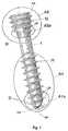
- FIG. 1is a side view of a screw according to a first embodiment of the invention
- FIGS. 2 a and 2 bare views in longitudinal section along the main axis of the screw, respectively of the distal portion and of the proximal portion;
- FIGS. 3 a and 3 bare cross sections at the cutting ridges in a reference position ( FIG. 3 a ) and after a slight screwing in (approximately 1/30th of a turn) ( FIG. 3 b ).
- FIG. 1shows a general view of the screw according to the embodiment of the invention most particularly described here, which shows two anchoring zones, namely a distal portion A 1 and a proximal portion A 2 .
- the core formed with the screwthreadalso called the barrel f, is generally cylindrical.
- f 1is the portion of the barrel of the zone A 1 at the distal end A 1 , that is to say the body of the screw except for the threads
- f 2is the portion of the barrel of the zone A 2 at the proximal end A 2 .
- Each zone A 1 and A 2has threads P and forms an attack zone (the first to come into contact with the bone and to bite into it when screwing in) A 1 a at the distal end, and A 2 a at the proximal end followed by a screwing zone.
- the distal and proximal attack zones A 1 a and A 2 aeach comprise several teeth D, for example three teeth each defining a cutting ridge AR. These teeth D are formed by a notch or cut parallel to a main axis AP of the screw in order to create a cutting ridge AR at the intersection of this milling with the outer edge of the thread of the screw P.
- FIG. 2 ashows more precisely a longitudinal section of the screw in the distal portion.
- a 1is defined as the angle between the main axis AP and a straight line D 1 connecting the roots of the threads P, or corresponding to the external surface of the barrel f 1 excluding the threads.
- the angle b 1is also defined as the angle between the main axis AP and the straight line E 1 connecting the crests of the threads P.
- FIG. 2 bshows a longitudinal section of the screw in the proximal portion.
- a 2is defined as the angle between the main axis AP and the straight line D 2 connecting the roots of the threads P, or corresponding to the external surface of the barrel f 2 excluding the threads.
- angle b 2is defined as the angle between the main axis AP and the straight line E 2 connecting the crests of the threads P.
- FIG. 3 afor its part shows a cross section of the screw in the zone A 1 a , that is to say at the teeth D.
- the sectionis identical in the zone A 2 a and is therefore not shown.
- the cross-hatched zone fcorresponds to the tubular barrel of the screw.
- the teeth Dare shown to be three in number, and produced by removal of material corresponding to a 1 ⁇ 2 rectangle (L 1 -L 2 ).
- the cutting ridges ARcorrespond to the intersection of the side L 2 with the outside of the thread P.
- AxRis a radial axis of the screw.
- FIG. 3 bshows the same section after a slight rotation through an angle C.
- This angle Ccorresponds to the angle between the radial axis AxR passing through the cutting ridge AR and the side L 2 .
- the distal end of the barrelnamely f 1 at the distal end and f 2 at the proximal end (corresponding to the thread bottoms) is slightly conical, both at the distal end A 1 a and at the proximal end A 2 a , with an angle a 1 at the distal end and a 2 at the proximal end.
- This conicity of the barrel fis associated with a conicity of the crest of the thread angle b 1 at the distal end and b 2 at the proximal end that are large enough to allow an immediate engagement of the screw as soon as perforation begins.
- the thread of the screwis cut at the very bottom of the end A 1 a at the distal end A 2 a at the proximal end, respectively on this conical trajectory, that is to say that the thread depth increases very rapidly which makes it possible to have a significant thread height as close as possible to the end.
- the cutting ridges ARare three in number, the sum of the angles (a 1 +b 1 at the distal end and a 2 +b 2 at the proximal end, respectively) is between 50° and 70°, and/or the angle a 1 at the distal end is between 4° and 10° and the angle a 2 at the proximal end is between 10° and 20°.
- the distal diameter of the distal endis 1.8 mm to allow good penetration.
- the angle a 1is 6°
- the angle a 2is 15°
- the cutting ridgesare obtained by the machining of a closed L by the external diameter of the thread P of the screw.
- This Lis formed by a long side L 1 and a short side L 2 ( FIG. 3 ).
- the depth of the cutting ridges ARis less than or equal to the depth of the screwthread.
- the position of the plane defined in cross section by the straight line L 2 where it intersects the threadrepresents the cutting ridge AR is offset rearward (or negatively) (in the screwing-in direction), to a radial axis of the screw AxR so that, when turning as can be seen in FIG. 3 b , these ridges AR attack the bone with an angle C, defined in cross section between the radial axis passing through AR and the straight line L 2 .
- the cutting ridges ARare offset negatively relative to an axis radial to the screw, that is to say rearward relative to the direction of rotation of the screw when screwing in, for example the cutting ridges AR are offset rearward in order to have a bone attack angle C when screwing in (at the distal and proximal ends) of between 5° and 12°.
- the external end of the headmay be completely conical, for penetrating into the bone, or have a flat head in order to press on the external surface of the bone.
- the surgeonwill first of all bring together the two pieces of bone placing them next to one another in their fusion position.
- the different pitches of the screwsthen have an effect of bringing together and of compressing the bone portions, which effect is increased at the end of screwing in by the conical aspect of the ends of the two distal and proximal portions in an increased manner.
Landscapes
- Health & Medical Sciences (AREA)
- Orthopedic Medicine & Surgery (AREA)
- Surgery (AREA)
- Life Sciences & Earth Sciences (AREA)
- Heart & Thoracic Surgery (AREA)
- Nuclear Medicine, Radiotherapy & Molecular Imaging (AREA)
- Engineering & Computer Science (AREA)
- Biomedical Technology (AREA)
- Neurology (AREA)
- Medical Informatics (AREA)
- Molecular Biology (AREA)
- Animal Behavior & Ethology (AREA)
- General Health & Medical Sciences (AREA)
- Public Health (AREA)
- Veterinary Medicine (AREA)
- Surgical Instruments (AREA)
Abstract
Description
- distal end of the screw: corresponds to the portion that first comes into contact with the bone;
- proximal (or head) end: corresponds to the portion that is screwed in last and that comprises the connection to a screwing means (screwdriver for example);
- barrel of the screw: corresponds to the core or generally cylindrical portion on which the screwthread is positioned.
- in that the sum of the angles a1+b1 at the distal end and a2+b2 at the proximal end, defined between, on the one hand, the main axis (AP) of the screw and the external conicity of the barrel ((f1) at the distal end and (f2) at the proximal end), namely (a1) at the distal end, (a2) at the proximal end and, on the other hand, between the main axis (AP) of the screw and the crest line of the threads (P) of the screwthread, namely (b1) at the distal end and (b2) at the proximal end, is greater than 45°,
- and in that the attack portion, that is to say the most distal of each thread, has a plurality of cutting ridges (AR) obtained by removal of material.
- the cutting ridges (AR) are offset negatively relative to a radial axis of the screw, that is to say rearward relative to the direction of rotation of the screw when screwing in;
- the cutting ridges (AR) are offset rearward in order to present a bone attack angle when screwing in (C) (at the distal end and at the proximal end) of between 5° and 12°;
- the cutting ridges (AR) are preferably three in number;
- the depth of the cutting ridges (AR) is less than or equal to the depth of the screwthread;
- the depth of the cutting ridges (AR) is equal to the depth of the screwthread;
- the sum of the angles (a1+b1) at the distal end and (a2+b2) at the proximal end, respectively is between 50° and 70°;
- the angle (a1) at the distal end is between 4° and 10° and the angle (a2) at the proximal end is between 10° and 20°;
- the cutting ridges (AR) have a relief of approximately 10° rearward in the direction of is screwing in;
- the screw has a flat or conical head.
Claims (20)
Applications Claiming Priority (3)
| Application Number | Priority Date | Filing Date | Title |
|---|---|---|---|
| FR0900557 | 2009-02-09 | ||
| FR0900557AFR2941859B1 (en) | 2009-02-09 | 2009-02-09 | OSTEOSYNTHESIS SCREW. |
| PCT/FR2010/000094WO2010089481A1 (en) | 2009-02-09 | 2010-02-09 | Screw for osteosynthesis and arthrodesis |
Related Parent Applications (1)
| Application Number | Title | Priority Date | Filing Date |
|---|---|---|---|
| PCT/FR2010/000094A-371-Of-InternationalWO2010089481A1 (en) | 2009-02-09 | 2010-02-09 | Screw for osteosynthesis and arthrodesis |
Related Child Applications (1)
| Application Number | Title | Priority Date | Filing Date |
|---|---|---|---|
| US14/657,308ContinuationUS9504504B2 (en) | 2009-02-09 | 2015-03-13 | Screw for osteosynthesis and arthrodesis |
Publications (2)
| Publication Number | Publication Date |
|---|---|
| US20110313473A1 US20110313473A1 (en) | 2011-12-22 |
| US9011505B2true US9011505B2 (en) | 2015-04-21 |
Family
ID=41105234
Family Applications (2)
| Application Number | Title | Priority Date | Filing Date |
|---|---|---|---|
| US13/146,925Active2030-05-23US9011505B2 (en) | 2009-02-09 | 2010-02-09 | Screw for osteosynthesis and arthrodesis |
| US14/657,308Active2030-05-01US9504504B2 (en) | 2009-02-09 | 2015-03-13 | Screw for osteosynthesis and arthrodesis |
Family Applications After (1)
| Application Number | Title | Priority Date | Filing Date |
|---|---|---|---|
| US14/657,308Active2030-05-01US9504504B2 (en) | 2009-02-09 | 2015-03-13 | Screw for osteosynthesis and arthrodesis |
Country Status (4)
| Country | Link |
|---|---|
| US (2) | US9011505B2 (en) |
| EP (1) | EP2393441B1 (en) |
| FR (1) | FR2941859B1 (en) |
| WO (1) | WO2010089481A1 (en) |
Cited By (18)
| Publication number | Priority date | Publication date | Assignee | Title |
|---|---|---|---|---|
| US20140135851A1 (en)* | 2012-11-09 | 2014-05-15 | Fellowship Of Orthopaedic Researchers, Inc. | Facet Screws |
| US20150105829A1 (en)* | 2012-05-22 | 2015-04-16 | Austofix Group Limited | Bone fixation device |
| USD814280S1 (en)* | 2016-09-27 | 2018-04-03 | General Electric Company | Fastener |
| US20180125553A1 (en)* | 2015-04-15 | 2018-05-10 | Klaus Pastl | Bone screw |
| US20190070009A1 (en)* | 2017-09-05 | 2019-03-07 | ExsoMed Corporation | Small bone tapered compression screw |
| US10702324B2 (en) | 2017-02-27 | 2020-07-07 | Osteomed Llc | Reduction tool |
| WO2020239959A1 (en) | 2019-05-31 | 2020-12-03 | Innovation Advances Limited | Osteotomy method and device |
| US11033310B2 (en) | 2017-08-15 | 2021-06-15 | Gomboc, LLC | Magnetic screw and plate apparatus |
| US11147681B2 (en) | 2017-09-05 | 2021-10-19 | ExsoMed Corporation | Small bone angled compression screw |
| US11191570B2 (en) | 2017-05-03 | 2021-12-07 | Advance Research System, Llc | Extension ready spinal support systems |
| US11291488B1 (en) | 2021-02-24 | 2022-04-05 | Medshape, Inc. | Dynamic compression devices and processes for making and using same |
| US11291487B2 (en)* | 2018-12-21 | 2022-04-05 | Azurmeds Inc. | Screw fixation device, fixation kit and fixation method |
| US20220378986A1 (en)* | 2020-02-19 | 2022-12-01 | Olympus Terumo Biomaterials Corp. | Implant |
| US20230009126A1 (en)* | 2019-12-19 | 2023-01-12 | Hilti Aktiengesellschaft | Fastener and façade |
| US11648037B2 (en) | 2017-05-03 | 2023-05-16 | Advance Research System, Llc | Extension-ready spinal support system with vascular-safe pedicle screw |
| USD1019954S1 (en) | 2021-02-24 | 2024-03-26 | Medshape, Inc. | Dynamic compression device |
| US12023068B2 (en) | 2021-03-02 | 2024-07-02 | Medshape, Inc. | Resorption-controlled compression devices and processes for making and using the same |
| US12035951B1 (en)* | 2023-04-12 | 2024-07-16 | OC Medical Devices, LLC | Orthopedic implants |
Families Citing this family (25)
| Publication number | Priority date | Publication date | Assignee | Title |
|---|---|---|---|---|
| FR2971413B1 (en)* | 2011-02-15 | 2013-12-27 | Jean-Pierre Py | SCREW FOR MEDICAL USE, PARTICULARLY FOR REALIZING A OSTEOSYNTHESIS |
| CA2829565A1 (en)* | 2011-03-10 | 2012-09-13 | DePuy Synthes Products, LLC | Awl screw fixation members and related systems |
| FR2990618B1 (en)* | 2012-05-21 | 2015-04-03 | Neosteo | AUTOCOMPRESSIVE SCREW OF OSTEOSYNTHESIS |
| US9079263B2 (en)* | 2012-08-24 | 2015-07-14 | RTG Scientific, Inc. | Orthopedic fastener method |
| US9962190B2 (en)* | 2013-01-15 | 2018-05-08 | Friedrich Müller | MTV implantation set |
| US20140214034A1 (en) | 2013-01-25 | 2014-07-31 | Fady Rayes | Cannulated telescopic femoral neck screw device and related fixation method |
| US9687284B2 (en) | 2013-02-13 | 2017-06-27 | Stryker European Holdings I, Llc | Locking peg with extended thread |
| WO2014127435A1 (en)* | 2013-02-20 | 2014-08-28 | Nassri Paulo Henrique Giazzi | Surgical rehabilitation system using a set of biocompatible implantable metallic devices which are innovative, optimized components |
| DE102013107170A1 (en)* | 2013-07-08 | 2015-01-22 | Aesculap Ag | bone screw |
| CN106102612B (en) | 2013-11-11 | 2020-07-21 | 阿特雷克斯公司 | Screw for generating and applying compression in the body |
| EP3068325B1 (en) | 2013-11-13 | 2021-09-15 | Arthrex, Inc. | Intermedullary devices for generating and applying compression within a body |
| WO2016123382A1 (en) | 2015-01-28 | 2016-08-04 | Mx Orthopedics, Corp. | Self-compressing screws for generating and applying compression within a body |
| WO2016154417A1 (en) | 2015-03-24 | 2016-09-29 | Mẍ Orthopedics, Corp. | Staples for generating and applying compression within a body |
| ES2608049B1 (en)* | 2015-10-05 | 2018-02-27 | Industrial Medica Alicantina, S.L. | Self-tapping screw for bone surgical operations |
| RU2611742C1 (en)* | 2015-12-16 | 2017-02-28 | Федеральное государственное бюджетное образовательное учреждение высшего образования Первый Московский государственный медицинский университет имени И.М. Сеченова Министерства здравоохранения Российской Федерации (ФГБОУ ВО Первый МГМУ им. И.М. Сеченова Минздрава России) | Method for surgery of ankle fractures |
| US11766282B2 (en)* | 2017-02-22 | 2023-09-26 | In2Bones Usa, Llc | Adjustable angle bone fixation assembly |
| KR102230600B1 (en)* | 2019-01-29 | 2021-03-22 | 고려대학교 산학협력단 | Bone screw |
| USD916282S1 (en)* | 2019-02-14 | 2021-04-13 | Field Orthopaedics Pty Ltd | Surgical screw |
| RU2706140C1 (en)* | 2019-02-19 | 2019-11-14 | Государственное бюджетное учреждение Санкт-Петербургский научно-исследовательский институт скорой помощи им. И.И. Джанелидзе Российской Федерации | Cannulated screw for minimally invasive osteosynthesis of unstable pelvic ring injuries |
| IT201900003285A1 (en)* | 2019-03-06 | 2020-09-06 | Orthofix Srl | Telescopic nail and related perforating instruments |
| US11867216B2 (en)* | 2020-06-04 | 2024-01-09 | Hando Kim | Compliant self-anchoring screw with auxetic properties |
| KR102163998B1 (en)* | 2020-06-30 | 2020-10-12 | (주)이노메디텍 | Bone fixation screw with easy insertion and removal |
| RU2756428C1 (en)* | 2020-12-09 | 2021-09-30 | Александр Иванович Колесник | Device for open reposition of displaced columns of acetabulum |
| ES2957176A1 (en)* | 2022-05-30 | 2024-01-12 | Silberberg Jose Maria | Surgical screw (Machine-translation by Google Translate, not legally binding) |
| PL131821U1 (en)* | 2023-12-20 | 2025-06-23 | Piotr Morasiewicz | Cannulated ankle screw |
Citations (89)
| Publication number | Priority date | Publication date | Assignee | Title |
|---|---|---|---|---|
| US1677269A (en) | 1925-12-21 | 1928-07-17 | Thomas N Burghart | Nonremovable nut |
| US2174578A (en) | 1938-10-01 | 1939-10-03 | Harry C Graham | Dowel |
| US2242003A (en) | 1940-06-13 | 1941-05-13 | Frank A Lorenzo | Method and apparatus for reduction of fracture of femur |
| US2247499A (en) | 1939-11-28 | 1941-07-01 | Eastman Kodak Co | Screw stick |
| US3512447A (en) | 1968-09-09 | 1970-05-19 | Rudolph Marion Vaughn | Frangible nut fastener |
| US3537288A (en) | 1965-10-22 | 1970-11-03 | P D Robertson Mfg Co Ltd | Method of manufacturing self-tapping screws |
| USRE28111E (en) | 1971-01-04 | 1974-08-13 | Fastener with improved threadconstruction | |
| US3929054A (en) | 1972-12-01 | 1975-12-30 | Elco Industries Inc | Fastening element adapted for tightening to predetermined torque |
| US4175555A (en) | 1977-02-24 | 1979-11-27 | Interfix Limited | Bone screw |
| US4463753A (en) | 1980-01-04 | 1984-08-07 | Gustilo Ramon B | Compression bone screw |
| US4537185A (en) | 1983-06-10 | 1985-08-27 | Denis P. Stednitz | Cannulated fixation screw |
| US4621963A (en) | 1984-03-26 | 1986-11-11 | Elco Industries, Inc. | Fastener for roof assemblies and the like |
| US4640271A (en) | 1985-11-07 | 1987-02-03 | Zimmer, Inc. | Bone screw |
| US4653244A (en) | 1986-01-16 | 1987-03-31 | Farrell Mark A | Fastener element |
| US4778319A (en) | 1986-03-06 | 1988-10-18 | Siegfried Schule | Self-tapping screw |
| US4940467A (en) | 1988-02-03 | 1990-07-10 | Tronzo Raymond G | Variable length fixation device |
| US4950270A (en) | 1989-02-03 | 1990-08-21 | Boehringer Mannheim Corporation | Cannulated self-tapping bone screw |
| USRE33348E (en) | 1985-11-07 | 1990-09-25 | Zimmer, Inc. | Bone screw |
| US5019079A (en) | 1989-11-20 | 1991-05-28 | Zimmer, Inc. | Bone screw |
| US5052719A (en) | 1989-09-01 | 1991-10-01 | Alfred Teves Gmbh | Methods and apparatus for fixing a pipeline to a coupling |
| US5415507A (en) | 1993-07-29 | 1995-05-16 | Elco Industries, Inc. | Anchor with adjustable seal |
| US5456685A (en) | 1994-02-14 | 1995-10-10 | Smith & Nephew Dyonics, Inc. | Interference screw having a tapered back root |
| US5474408A (en) | 1993-11-04 | 1995-12-12 | Transpo Industries, Inc. | Break-away coupling with spaced weakened sections |
| US5643269A (en) | 1990-08-24 | 1997-07-01 | Haerle; Anton | Externally threaded bodies for use as taps or screws |
| US5653710A (en) | 1993-11-23 | 1997-08-05 | Haerle; Anton | Osteosynthetic force transmitting member |
| US5746039A (en) | 1996-05-31 | 1998-05-05 | Metaltite Corporation | Truss fastener and truss assembly |
| US5816012A (en) | 1997-03-10 | 1998-10-06 | Alpine Engineered Products, Inc. | Dual threaded fastener and metal component assembly |
| US5827031A (en) | 1997-05-14 | 1998-10-27 | Swallow; Gregory T. | Self starting finishing screw and driver tool |
| US5857816A (en) | 1994-10-17 | 1999-01-12 | Anglo Dutch International Finance N.V. | Torque-limiting fastening device |
| US5863167A (en) | 1995-08-22 | 1999-01-26 | Max Co.,Ltd | Drilling screw for fixing gypsum board to thin steel plate |
| US5868749A (en) | 1996-04-05 | 1999-02-09 | Reed; Thomas M. | Fixation devices |
| US5871486A (en) | 1993-01-21 | 1999-02-16 | Acumed, Inc. | Variable pitch bone screw |
| US5899906A (en) | 1996-01-18 | 1999-05-04 | Synthes (U.S.A.) | Threaded washer |
| US6004321A (en)* | 1998-03-19 | 1999-12-21 | Graser; Robert E. | Cannulated screw retraction apparatus and method of retraction |
| US6022177A (en) | 1997-11-20 | 2000-02-08 | Meyer Liestal Ag | Spacer screw |
| US6030162A (en) | 1998-12-18 | 2000-02-29 | Acumed, Inc. | Axial tension screw |
| US6039738A (en) | 1997-07-03 | 2000-03-21 | Depuy Orthopaedics, Inc. | Fastener |
| US6053653A (en) | 1997-05-09 | 2000-04-25 | Sannohashi Corporation | Fastening method, fastening system and bolt used therefor |
| US6074149A (en) | 1999-06-30 | 2000-06-13 | G. Lyle Habermehl | False threadscrew and screwstrip |
| US6264677B1 (en)* | 1997-10-15 | 2001-07-24 | Applied Biological Concepts, Inc. | Wedge screw suture anchor |
| US6283973B1 (en) | 1998-12-30 | 2001-09-04 | Depuy Orthopaedics, Inc. | Strength fixation device |
| US6306140B1 (en)* | 2001-01-17 | 2001-10-23 | Synthes (Usa) | Bone screw |
| US6319254B1 (en) | 1999-04-22 | 2001-11-20 | Newdeal | Compression osteosynthesis screw, and an ancillaty device for use therewith |
| US6341917B1 (en) | 1998-12-30 | 2002-01-29 | Emhart Inc. | Double ended stud fastening system |
| US6402757B1 (en) | 1999-03-12 | 2002-06-11 | Biomet, Inc. | Cannulated fastener system for repair of bone fracture |
| US20020087161A1 (en) | 2001-01-03 | 2002-07-04 | Randall Bernard L. | Cannulated locking screw system especially for transiliac implant |
| US6436100B1 (en) | 1998-08-07 | 2002-08-20 | J. Lee Berger | Cannulated internally threaded bone screw and reduction driver device |
| US6440136B1 (en) | 2000-05-24 | 2002-08-27 | Medtronic Ps Medical, Inc. | Apparatus for attaching to bone |
| US20020198527A1 (en) | 2001-06-21 | 2002-12-26 | Helmut Muckter | Implantable screw for stabilization of a joint or a bone fracture |
| US20030059270A1 (en) | 2001-09-21 | 2003-03-27 | O'berry Patrick Brian | Double pitch screw |
| US20030078584A1 (en) | 2001-10-18 | 2003-04-24 | Kishore Tipirneni | System and method for fixation of bone fractures |
| EP0856293B1 (en) | 1997-02-04 | 2003-05-28 | S.C.I. Digo | Bone screw for connecting small bone fragments |
| US20030120277A1 (en) | 1998-08-07 | 2003-06-26 | Berger J. Lee | Cannulated internally threaded bone screw with aperatured insert |
| FR2840799A1 (en) | 2002-06-17 | 2003-12-19 | Fixano | Osteosynthesis screw comprises axial bore and distal machine notches in wall delimiting two radial faces forming cutting edges with bore, external skin surfaces together with cutting edges enable screw to be self-tapping |
| EP1378205A1 (en) | 2002-07-05 | 2004-01-07 | Newdeal S.A. | Compression screw for osteosynthesis |
| US20040006345A1 (en) | 2002-02-12 | 2004-01-08 | Pioneer Laboratories, Inc. | Cannulated bone screw |
| US6739815B2 (en) | 2001-07-27 | 2004-05-25 | Yao Seibyo Co., Ltd. | Wood screw |
| WO2004069031A2 (en) | 2003-02-03 | 2004-08-19 | Kinetikos Medical Incorporated | Compression screw apparatuses, systems and methods |
| US20040172031A1 (en) | 2003-02-27 | 2004-09-02 | Reinhard Rubecamp | Compression bone screw and screwdriver blade therefor |
| US20040225292A1 (en) | 2003-05-05 | 2004-11-11 | Sasso Ricardo C. | Bone anchor and methods of using the same |
| US20050101961A1 (en) | 2003-11-12 | 2005-05-12 | Huebner Randall J. | Bone screws |
| US6918727B2 (en) | 2002-05-01 | 2005-07-19 | Joker Industrial Co., Ltd. | Anchoring screw with double heads and triple threads of different depths of thread |
| US6955677B2 (en) | 2002-10-15 | 2005-10-18 | The University Of North Carolina At Chapel Hill | Multi-angular fastening apparatus and method for surgical bone screw/plate systems |
| US20060015105A1 (en) | 2003-05-06 | 2006-01-19 | Christopher Warren | Proximal anchors for bone fixation system |
| US20060074419A1 (en) | 2004-10-05 | 2006-04-06 | Taylor Harold S | Spinal implants with multi-axial anchor assembly and methods |
| US7037309B2 (en) | 2001-07-05 | 2006-05-02 | Depuy (Ireland) Limted | Self-tapping screw for small-bone surgery |
| US20060173461A1 (en) | 2005-01-28 | 2006-08-03 | Kay David B | Cannulated orthopedic screw |
| US20060217727A1 (en)* | 2002-06-21 | 2006-09-28 | Chad Munro | Bone screw |
| US7213999B2 (en) | 2004-01-30 | 2007-05-08 | Torque-Traction Technologies, Llc. | Fastener with opposite hand threads for securing two components together |
| US7316532B2 (en) | 2003-02-12 | 2008-01-08 | Synthes (U.S.A.) | Screw with integrated screwdriver |
| US7367768B2 (en) | 2001-08-06 | 2008-05-06 | Omg, Inc. | Deck screw and installation method for composite lumber |
| US20080119855A1 (en) | 2005-02-19 | 2008-05-22 | Aesculap Ag & Co. Kg | Orthopedic fixation system |
| US20080147128A1 (en) | 2006-12-15 | 2008-06-19 | Zimmer Technology, Inc. | Cannulated bone screw and cannulated driver for the implantation thereof |
| US20080188899A1 (en) | 2007-02-07 | 2008-08-07 | Apex Biomedical Company, Llc | Rotationally asymmetric bone screw |
| US20080234763A1 (en)* | 2007-03-16 | 2008-09-25 | Patterson Chad J | Surgical compression bone screw |
| US20080234752A1 (en) | 2007-03-21 | 2008-09-25 | The University Of North Carolina At Chapel Hill | Surgical plate puller devices and methods for use with surgical bone screw/plate systems |
| US20080306555A1 (en) | 2007-06-07 | 2008-12-11 | Patterson Chad J | Bone screw washer |
| US20090105768A1 (en) | 2000-02-16 | 2009-04-23 | Trans1 | Dual anchor prosthetic nucleus apparatus |
| US20090131990A1 (en) | 2001-10-18 | 2009-05-21 | Kishore Tipirneni | Bone screw system and method |
| US20090198289A1 (en) | 2008-02-02 | 2009-08-06 | Manderson Easton L | Fortified cannulated screw |
| US20090254129A1 (en) | 2007-04-30 | 2009-10-08 | Kishore Tipirneni | Bone screw system and method for the fixation of bone fractures |
| US20100069970A1 (en) | 2008-09-16 | 2010-03-18 | Lewis Derek S | Orthopedic compression screw |
| US20100114315A1 (en) | 2008-10-31 | 2010-05-06 | Manderson Easton L | Intramedullary locked compression screw for stabilization and union of complex ankle and subtalar deformities |
| US7731738B2 (en) | 2005-12-09 | 2010-06-08 | Orthopro, Llc | Cannulated screw |
| US20100268285A1 (en) | 2001-10-18 | 2010-10-21 | Orthoip, Llc | Bone screw system and method for the fixation of bone fractures |
| US7905909B2 (en) | 2005-09-19 | 2011-03-15 | Depuy Products, Inc. | Bone stabilization system including multi-directional threaded fixation element |
| US8070786B2 (en) | 1993-01-21 | 2011-12-06 | Acumed Llc | System for fusing joints |
| US8157803B1 (en) | 2007-08-21 | 2012-04-17 | Surgical Implant Generation Network | Bone fixation using an intramedullary nail interlocked with a buttress member |
| US8668725B2 (en) | 2007-07-13 | 2014-03-11 | Southern Spine, Llc | Bone screw |
- 2009
- 2009-02-09FRFR0900557Apatent/FR2941859B1/ennot_activeExpired - Fee Related
- 2010
- 2010-02-09EPEP10707077.3Apatent/EP2393441B1/enactiveActive
- 2010-02-09USUS13/146,925patent/US9011505B2/enactiveActive
- 2010-02-09WOPCT/FR2010/000094patent/WO2010089481A1/enactiveApplication Filing
- 2015
- 2015-03-13USUS14/657,308patent/US9504504B2/enactiveActive
Patent Citations (107)
| Publication number | Priority date | Publication date | Assignee | Title |
|---|---|---|---|---|
| US1677269A (en) | 1925-12-21 | 1928-07-17 | Thomas N Burghart | Nonremovable nut |
| US2174578A (en) | 1938-10-01 | 1939-10-03 | Harry C Graham | Dowel |
| US2247499A (en) | 1939-11-28 | 1941-07-01 | Eastman Kodak Co | Screw stick |
| US2242003A (en) | 1940-06-13 | 1941-05-13 | Frank A Lorenzo | Method and apparatus for reduction of fracture of femur |
| US3537288A (en) | 1965-10-22 | 1970-11-03 | P D Robertson Mfg Co Ltd | Method of manufacturing self-tapping screws |
| US3512447A (en) | 1968-09-09 | 1970-05-19 | Rudolph Marion Vaughn | Frangible nut fastener |
| USRE28111E (en) | 1971-01-04 | 1974-08-13 | Fastener with improved threadconstruction | |
| US3929054A (en) | 1972-12-01 | 1975-12-30 | Elco Industries Inc | Fastening element adapted for tightening to predetermined torque |
| US4175555A (en) | 1977-02-24 | 1979-11-27 | Interfix Limited | Bone screw |
| US4463753A (en) | 1980-01-04 | 1984-08-07 | Gustilo Ramon B | Compression bone screw |
| US4537185A (en) | 1983-06-10 | 1985-08-27 | Denis P. Stednitz | Cannulated fixation screw |
| US4621963A (en) | 1984-03-26 | 1986-11-11 | Elco Industries, Inc. | Fastener for roof assemblies and the like |
| USRE33348E (en) | 1985-11-07 | 1990-09-25 | Zimmer, Inc. | Bone screw |
| US4640271A (en) | 1985-11-07 | 1987-02-03 | Zimmer, Inc. | Bone screw |
| US4653244A (en) | 1986-01-16 | 1987-03-31 | Farrell Mark A | Fastener element |
| US4778319A (en) | 1986-03-06 | 1988-10-18 | Siegfried Schule | Self-tapping screw |
| US4940467A (en) | 1988-02-03 | 1990-07-10 | Tronzo Raymond G | Variable length fixation device |
| US4950270A (en) | 1989-02-03 | 1990-08-21 | Boehringer Mannheim Corporation | Cannulated self-tapping bone screw |
| US5052719A (en) | 1989-09-01 | 1991-10-01 | Alfred Teves Gmbh | Methods and apparatus for fixing a pipeline to a coupling |
| US5019079A (en) | 1989-11-20 | 1991-05-28 | Zimmer, Inc. | Bone screw |
| US5643269A (en) | 1990-08-24 | 1997-07-01 | Haerle; Anton | Externally threaded bodies for use as taps or screws |
| US8070786B2 (en) | 1993-01-21 | 2011-12-06 | Acumed Llc | System for fusing joints |
| US5871486A (en) | 1993-01-21 | 1999-02-16 | Acumed, Inc. | Variable pitch bone screw |
| US5415507A (en) | 1993-07-29 | 1995-05-16 | Elco Industries, Inc. | Anchor with adjustable seal |
| US5474408A (en) | 1993-11-04 | 1995-12-12 | Transpo Industries, Inc. | Break-away coupling with spaced weakened sections |
| US5653710A (en) | 1993-11-23 | 1997-08-05 | Haerle; Anton | Osteosynthetic force transmitting member |
| US5456685A (en) | 1994-02-14 | 1995-10-10 | Smith & Nephew Dyonics, Inc. | Interference screw having a tapered back root |
| US5857816A (en) | 1994-10-17 | 1999-01-12 | Anglo Dutch International Finance N.V. | Torque-limiting fastening device |
| US5863167A (en) | 1995-08-22 | 1999-01-26 | Max Co.,Ltd | Drilling screw for fixing gypsum board to thin steel plate |
| US6048344A (en) | 1996-01-18 | 2000-04-11 | Synthes (U.S.A.) | Threaded washer and bone screw apparatus |
| US5899906A (en) | 1996-01-18 | 1999-05-04 | Synthes (U.S.A.) | Threaded washer |
| US5997541A (en) | 1996-01-18 | 1999-12-07 | Synthes (U.S.A) | Threaded washer |
| US5868749A (en) | 1996-04-05 | 1999-02-09 | Reed; Thomas M. | Fixation devices |
| US5968047A (en) | 1996-04-05 | 1999-10-19 | Reed; Thomas Mills | Fixation devices |
| US5746039A (en) | 1996-05-31 | 1998-05-05 | Metaltite Corporation | Truss fastener and truss assembly |
| EP0856293B1 (en) | 1997-02-04 | 2003-05-28 | S.C.I. Digo | Bone screw for connecting small bone fragments |
| US5816012A (en) | 1997-03-10 | 1998-10-06 | Alpine Engineered Products, Inc. | Dual threaded fastener and metal component assembly |
| US6053653A (en) | 1997-05-09 | 2000-04-25 | Sannohashi Corporation | Fastening method, fastening system and bolt used therefor |
| US5827031A (en) | 1997-05-14 | 1998-10-27 | Swallow; Gregory T. | Self starting finishing screw and driver tool |
| US6039738A (en) | 1997-07-03 | 2000-03-21 | Depuy Orthopaedics, Inc. | Fastener |
| US6264677B1 (en)* | 1997-10-15 | 2001-07-24 | Applied Biological Concepts, Inc. | Wedge screw suture anchor |
| US6022177A (en) | 1997-11-20 | 2000-02-08 | Meyer Liestal Ag | Spacer screw |
| US6004321A (en)* | 1998-03-19 | 1999-12-21 | Graser; Robert E. | Cannulated screw retraction apparatus and method of retraction |
| US6981974B2 (en) | 1998-08-07 | 2006-01-03 | Berger J Lee | Cannulated internally threaded bone screw with aperatured insert |
| US20030120277A1 (en) | 1998-08-07 | 2003-06-26 | Berger J. Lee | Cannulated internally threaded bone screw with aperatured insert |
| US20020169453A1 (en) | 1998-08-07 | 2002-11-14 | Berger J. Lee | Cannulated internally threaded bone screw |
| US6436100B1 (en) | 1998-08-07 | 2002-08-20 | J. Lee Berger | Cannulated internally threaded bone screw and reduction driver device |
| US6030162A (en) | 1998-12-18 | 2000-02-29 | Acumed, Inc. | Axial tension screw |
| US6283973B1 (en) | 1998-12-30 | 2001-09-04 | Depuy Orthopaedics, Inc. | Strength fixation device |
| US6672791B2 (en) | 1998-12-30 | 2004-01-06 | Newfrey Llc | Double ended fastening system |
| US6341917B1 (en) | 1998-12-30 | 2002-01-29 | Emhart Inc. | Double ended stud fastening system |
| US6402757B1 (en) | 1999-03-12 | 2002-06-11 | Biomet, Inc. | Cannulated fastener system for repair of bone fracture |
| US6319254B1 (en) | 1999-04-22 | 2001-11-20 | Newdeal | Compression osteosynthesis screw, and an ancillaty device for use therewith |
| US6074149A (en) | 1999-06-30 | 2000-06-13 | G. Lyle Habermehl | False threadscrew and screwstrip |
| US20090105768A1 (en) | 2000-02-16 | 2009-04-23 | Trans1 | Dual anchor prosthetic nucleus apparatus |
| US6440136B1 (en) | 2000-05-24 | 2002-08-27 | Medtronic Ps Medical, Inc. | Apparatus for attaching to bone |
| US6635059B2 (en) | 2001-01-03 | 2003-10-21 | Bernard L. Randall | Cannulated locking screw system especially for transiliac implant |
| US20020087161A1 (en) | 2001-01-03 | 2002-07-04 | Randall Bernard L. | Cannulated locking screw system especially for transiliac implant |
| US6306140B1 (en)* | 2001-01-17 | 2001-10-23 | Synthes (Usa) | Bone screw |
| WO2002056778A1 (en) | 2001-01-17 | 2002-07-25 | Synthes (U.S.A.) | Bone screw |
| US20020198527A1 (en) | 2001-06-21 | 2002-12-26 | Helmut Muckter | Implantable screw for stabilization of a joint or a bone fracture |
| US7037309B2 (en) | 2001-07-05 | 2006-05-02 | Depuy (Ireland) Limted | Self-tapping screw for small-bone surgery |
| US6739815B2 (en) | 2001-07-27 | 2004-05-25 | Yao Seibyo Co., Ltd. | Wood screw |
| US7367768B2 (en) | 2001-08-06 | 2008-05-06 | Omg, Inc. | Deck screw and installation method for composite lumber |
| US20030059270A1 (en) | 2001-09-21 | 2003-03-27 | O'berry Patrick Brian | Double pitch screw |
| US20100268285A1 (en) | 2001-10-18 | 2010-10-21 | Orthoip, Llc | Bone screw system and method for the fixation of bone fractures |
| US6736819B2 (en) | 2001-10-18 | 2004-05-18 | Kishore Tipirneni | System and method for fixation of bone fractures |
| US20040172030A1 (en) | 2001-10-18 | 2004-09-02 | Kishore Tipirrneni | System and method for the fixation of bone fractures |
| US7591823B2 (en) | 2001-10-18 | 2009-09-22 | Lagwire, Llc | System and method for the fixation of bone fractures |
| US20030078584A1 (en) | 2001-10-18 | 2003-04-24 | Kishore Tipirneni | System and method for fixation of bone fractures |
| US20090131990A1 (en) | 2001-10-18 | 2009-05-21 | Kishore Tipirneni | Bone screw system and method |
| US7207994B2 (en) | 2002-02-12 | 2007-04-24 | Pioneer Laboratories, Inc. | Cannulated bone screw |
| US20040006345A1 (en) | 2002-02-12 | 2004-01-08 | Pioneer Laboratories, Inc. | Cannulated bone screw |
| US6918727B2 (en) | 2002-05-01 | 2005-07-19 | Joker Industrial Co., Ltd. | Anchoring screw with double heads and triple threads of different depths of thread |
| FR2840799A1 (en) | 2002-06-17 | 2003-12-19 | Fixano | Osteosynthesis screw comprises axial bore and distal machine notches in wall delimiting two radial faces forming cutting edges with bore, external skin surfaces together with cutting edges enable screw to be self-tapping |
| US20060217727A1 (en)* | 2002-06-21 | 2006-09-28 | Chad Munro | Bone screw |
| EP1378205A1 (en) | 2002-07-05 | 2004-01-07 | Newdeal S.A. | Compression screw for osteosynthesis |
| US7708738B2 (en) | 2002-07-05 | 2010-05-04 | Newdeal S.A. | Self-boring and self-tapping screw for osteosynthesis and compression |
| US6955677B2 (en) | 2002-10-15 | 2005-10-18 | The University Of North Carolina At Chapel Hill | Multi-angular fastening apparatus and method for surgical bone screw/plate systems |
| US7582107B2 (en) | 2003-02-03 | 2009-09-01 | Integra Lifesciences Corporation | Compression screw apparatuses, systems and methods |
| WO2004069031A2 (en) | 2003-02-03 | 2004-08-19 | Kinetikos Medical Incorporated | Compression screw apparatuses, systems and methods |
| US7316532B2 (en) | 2003-02-12 | 2008-01-08 | Synthes (U.S.A.) | Screw with integrated screwdriver |
| US20060142770A1 (en) | 2003-02-27 | 2006-06-29 | Stryker Leibinger Gmbh & Co. Kg | Compression bone screw |
| US20040172031A1 (en) | 2003-02-27 | 2004-09-02 | Reinhard Rubecamp | Compression bone screw and screwdriver blade therefor |
| US7794483B2 (en) | 2003-02-27 | 2010-09-14 | Stryker Leibinger Gmbh & Co. Kg | Compression bone screw |
| US7044953B2 (en) | 2003-02-27 | 2006-05-16 | Stryker Leibinger Gmbh & Co. Kg | Compression bone screw |
| US20040225292A1 (en) | 2003-05-05 | 2004-11-11 | Sasso Ricardo C. | Bone anchor and methods of using the same |
| US20060015105A1 (en) | 2003-05-06 | 2006-01-19 | Christopher Warren | Proximal anchors for bone fixation system |
| US20050101961A1 (en) | 2003-11-12 | 2005-05-12 | Huebner Randall J. | Bone screws |
| US7213999B2 (en) | 2004-01-30 | 2007-05-08 | Torque-Traction Technologies, Llc. | Fastener with opposite hand threads for securing two components together |
| US7722654B2 (en) | 2004-10-05 | 2010-05-25 | Warsaw Orthopedic, Inc. | Spinal implants with multi-axial anchor assembly and methods |
| US20060074419A1 (en) | 2004-10-05 | 2006-04-06 | Taylor Harold S | Spinal implants with multi-axial anchor assembly and methods |
| US20060173461A1 (en) | 2005-01-28 | 2006-08-03 | Kay David B | Cannulated orthopedic screw |
| US20080119855A1 (en) | 2005-02-19 | 2008-05-22 | Aesculap Ag & Co. Kg | Orthopedic fixation system |
| US7905909B2 (en) | 2005-09-19 | 2011-03-15 | Depuy Products, Inc. | Bone stabilization system including multi-directional threaded fixation element |
| US7731738B2 (en) | 2005-12-09 | 2010-06-08 | Orthopro, Llc | Cannulated screw |
| US20080147128A1 (en) | 2006-12-15 | 2008-06-19 | Zimmer Technology, Inc. | Cannulated bone screw and cannulated driver for the implantation thereof |
| US20080188899A1 (en) | 2007-02-07 | 2008-08-07 | Apex Biomedical Company, Llc | Rotationally asymmetric bone screw |
| US20080234763A1 (en)* | 2007-03-16 | 2008-09-25 | Patterson Chad J | Surgical compression bone screw |
| US20080234752A1 (en) | 2007-03-21 | 2008-09-25 | The University Of North Carolina At Chapel Hill | Surgical plate puller devices and methods for use with surgical bone screw/plate systems |
| US20090254129A1 (en) | 2007-04-30 | 2009-10-08 | Kishore Tipirneni | Bone screw system and method for the fixation of bone fractures |
| US20080306555A1 (en) | 2007-06-07 | 2008-12-11 | Patterson Chad J | Bone screw washer |
| US8668725B2 (en) | 2007-07-13 | 2014-03-11 | Southern Spine, Llc | Bone screw |
| US8157803B1 (en) | 2007-08-21 | 2012-04-17 | Surgical Implant Generation Network | Bone fixation using an intramedullary nail interlocked with a buttress member |
| US20090198289A1 (en) | 2008-02-02 | 2009-08-06 | Manderson Easton L | Fortified cannulated screw |
| US20100069970A1 (en) | 2008-09-16 | 2010-03-18 | Lewis Derek S | Orthopedic compression screw |
| US20100114315A1 (en) | 2008-10-31 | 2010-05-06 | Manderson Easton L | Intramedullary locked compression screw for stabilization and union of complex ankle and subtalar deformities |
Cited By (27)
| Publication number | Priority date | Publication date | Assignee | Title |
|---|---|---|---|---|
| US20150105829A1 (en)* | 2012-05-22 | 2015-04-16 | Austofix Group Limited | Bone fixation device |
| US9968391B2 (en)* | 2012-11-09 | 2018-05-15 | Fellowship of Orthopaedic Researchers, LLC | Facet screws |
| US20140135851A1 (en)* | 2012-11-09 | 2014-05-15 | Fellowship Of Orthopaedic Researchers, Inc. | Facet Screws |
| US10709486B2 (en)* | 2015-04-15 | 2020-07-14 | Klaus Pastl | Bone screw |
| US20180125553A1 (en)* | 2015-04-15 | 2018-05-10 | Klaus Pastl | Bone screw |
| USD814280S1 (en)* | 2016-09-27 | 2018-04-03 | General Electric Company | Fastener |
| US10702324B2 (en) | 2017-02-27 | 2020-07-07 | Osteomed Llc | Reduction tool |
| US11191570B2 (en) | 2017-05-03 | 2021-12-07 | Advance Research System, Llc | Extension ready spinal support systems |
| US11648037B2 (en) | 2017-05-03 | 2023-05-16 | Advance Research System, Llc | Extension-ready spinal support system with vascular-safe pedicle screw |
| US12239345B2 (en) | 2017-05-03 | 2025-03-04 | Advance Research Systems, LLC | Extension ready spinal support systems |
| US11033310B2 (en) | 2017-08-15 | 2021-06-15 | Gomboc, LLC | Magnetic screw and plate apparatus |
| US11147681B2 (en) | 2017-09-05 | 2021-10-19 | ExsoMed Corporation | Small bone angled compression screw |
| US11191645B2 (en)* | 2017-09-05 | 2021-12-07 | ExsoMed Corporation | Small bone tapered compression screw |
| US20190070009A1 (en)* | 2017-09-05 | 2019-03-07 | ExsoMed Corporation | Small bone tapered compression screw |
| US12251316B2 (en) | 2017-09-05 | 2025-03-18 | ExsoMed Corporation | Small bone angled compression screw |
| US11291487B2 (en)* | 2018-12-21 | 2022-04-05 | Azurmeds Inc. | Screw fixation device, fixation kit and fixation method |
| US20220211421A1 (en)* | 2018-12-21 | 2022-07-07 | Azurmeds Inc. | Screw fixation method |
| US20220233223A1 (en)* | 2019-05-31 | 2022-07-28 | Innovation Advances Limited | Osteotomy method and device |
| WO2020239959A1 (en) | 2019-05-31 | 2020-12-03 | Innovation Advances Limited | Osteotomy method and device |
| US20230009126A1 (en)* | 2019-12-19 | 2023-01-12 | Hilti Aktiengesellschaft | Fastener and façade |
| US20220378986A1 (en)* | 2020-02-19 | 2022-12-01 | Olympus Terumo Biomaterials Corp. | Implant |
| US11744625B2 (en) | 2021-02-24 | 2023-09-05 | Medshape, Inc. | Dynamic compression devices and processes for making and using same |
| USD1019954S1 (en) | 2021-02-24 | 2024-03-26 | Medshape, Inc. | Dynamic compression device |
| US11291488B1 (en) | 2021-02-24 | 2022-04-05 | Medshape, Inc. | Dynamic compression devices and processes for making and using same |
| US12023068B2 (en) | 2021-03-02 | 2024-07-02 | Medshape, Inc. | Resorption-controlled compression devices and processes for making and using the same |
| US12035951B1 (en)* | 2023-04-12 | 2024-07-16 | OC Medical Devices, LLC | Orthopedic implants |
| US12226137B2 (en) | 2023-04-12 | 2025-02-18 | OC Medical Devices, LLC | Orthopedic implants and tools |
Also Published As
| Publication number | Publication date |
|---|---|
| FR2941859A1 (en) | 2010-08-13 |
| WO2010089481A1 (en) | 2010-08-12 |
| US20150182271A1 (en) | 2015-07-02 |
| FR2941859B1 (en) | 2012-04-06 |
| EP2393441A1 (en) | 2011-12-14 |
| US20110313473A1 (en) | 2011-12-22 |
| EP2393441B1 (en) | 2015-08-12 |
| US9504504B2 (en) | 2016-11-29 |
Similar Documents
| Publication | Publication Date | Title |
|---|---|---|
| US9011505B2 (en) | Screw for osteosynthesis and arthrodesis | |
| US11602383B2 (en) | Devices for generating and applying compression within a body | |
| JP6055445B2 (en) | Highly versatile variable angle bone plate system | |
| US7905909B2 (en) | Bone stabilization system including multi-directional threaded fixation element | |
| US6001101A (en) | Screw device with threaded head for permitting the coaptation of two bone fragments | |
| US6730091B1 (en) | Blockable bone plate | |
| US20170079698A1 (en) | Flexible bone implant | |
| EP2398414B1 (en) | Bone screw with channels | |
| EP4282359A2 (en) | Distal radius plate | |
| US20080292429A1 (en) | Thread-Forming Screw | |
| US12251316B2 (en) | Small bone angled compression screw | |
| US7637929B2 (en) | Self-drilling bone screw | |
| US20250177021A1 (en) | Orthopedic Bone Screw | |
| US11291484B2 (en) | Highly-versatile variable-angle bone plate system | |
| AU776105B2 (en) | Self-compressive osteosynthesis screw for small bone surgery | |
| JPH08112291A (en) | Screw fixing system | |
| Thakur | Locking Plates–Concepts and Applications | |
| CN107257667B (en) | Elongated pin for external fixator | |
| Iyer et al. | Importance of orthopaedic screws | |
| US20230225771A1 (en) | Flexible bone implant | |
| CN114533236A (en) | Fixing mechanism, bone plate, and bone treatment tool | |
| JP2013094628A (en) | External fixation pin |
Legal Events
| Date | Code | Title | Description |
|---|---|---|---|
| AS | Assignment | Owner name:MEMOMETAL TECHNOLOGIES, FRANCE Free format text:ASSIGNMENT OF ASSIGNORS INTEREST;ASSIGNORS:PRANDI, BERNARD;LARIVIERE, JEAN;R'TAIMATE, MOHAMMED;SIGNING DATES FROM 20110912 TO 20110914;REEL/FRAME:027232/0905 | |
| AS | Assignment | Owner name:MEMOMETAL TECHNOLOGIES, FRANCE Free format text:CONFIRMATORY ASSIGNMENT;ASSIGNOR:PRANDI, BERNARD;REEL/FRAME:030512/0411 Effective date:20130520 | |
| STCF | Information on status: patent grant | Free format text:PATENTED CASE | |
| AS | Assignment | Owner name:STRYKER EUROPEAN HOLDINGS V, LLC, MICHIGAN Free format text:NUNC PRO TUNC ASSIGNMENT;ASSIGNOR:MEMOMETAL TECHNOLOGIES SAS;REEL/FRAME:037118/0746 Effective date:20151008 Owner name:STRYKER EUROPEAN HOLDINGS I, LLC, MICHIGAN Free format text:NUNC PRO TUNC ASSIGNMENT;ASSIGNOR:STRYKER EUROPEAN HOLDINGS V, LLC;REEL/FRAME:037153/0168 Effective date:20151008 | |
| MAFP | Maintenance fee payment | Free format text:PAYMENT OF MAINTENANCE FEE, 4TH YEAR, LARGE ENTITY (ORIGINAL EVENT CODE: M1551); ENTITY STATUS OF PATENT OWNER: LARGE ENTITY Year of fee payment:4 | |
| AS | Assignment | Owner name:STRYKER EUROPEAN OPERATIONS HOLDINGS LLC, MICHIGAN Free format text:CHANGE OF NAME;ASSIGNOR:STRYKER EUROPEAN HOLDINGS III, LLC;REEL/FRAME:052860/0716 Effective date:20190226 Owner name:STRYKER EUROPEAN HOLDINGS III, LLC, DELAWARE Free format text:NUNC PRO TUNC ASSIGNMENT;ASSIGNOR:STRYKER EUROPEAN HOLDINGS I, LLC;REEL/FRAME:052861/0001 Effective date:20200519 | |
| MAFP | Maintenance fee payment | Free format text:PAYMENT OF MAINTENANCE FEE, 8TH YEAR, LARGE ENTITY (ORIGINAL EVENT CODE: M1552); ENTITY STATUS OF PATENT OWNER: LARGE ENTITY Year of fee payment:8 | |
| AS | Assignment | Owner name:STRYKER EUROPEAN OPERATIONS HOLDINGS LLC, MICHIGAN Free format text:CHANGE OF ADDRESS;ASSIGNOR:STRYKER EUROPEAN OPERATIONS HOLDINGS LLC;REEL/FRAME:069730/0754 Effective date:20241217 |