US9011388B2 - Passive safety portal device - Google Patents
Passive safety portal deviceDownload PDFInfo
- Publication number
- US9011388B2 US9011388B2US12/801,349US80134910AUS9011388B2US 9011388 B2US9011388 B2US 9011388B2US 80134910 AUS80134910 AUS 80134910AUS 9011388 B2US9011388 B2US 9011388B2
- Authority
- US
- United States
- Prior art keywords
- needle
- cap
- infuser
- leg
- port
- Prior art date
- Legal status (The legal status is an assumption and is not a legal conclusion. Google has not performed a legal analysis and makes no representation as to the accuracy of the status listed.)
- Expired - Fee Related, expires
Links
Images


Classifications
- A—HUMAN NECESSITIES
- A61—MEDICAL OR VETERINARY SCIENCE; HYGIENE
- A61M—DEVICES FOR INTRODUCING MEDIA INTO, OR ONTO, THE BODY; DEVICES FOR TRANSDUCING BODY MEDIA OR FOR TAKING MEDIA FROM THE BODY; DEVICES FOR PRODUCING OR ENDING SLEEP OR STUPOR
- A61M5/00—Devices for bringing media into the body in a subcutaneous, intra-vascular or intramuscular way; Accessories therefor, e.g. filling or cleaning devices, arm-rests
- A61M5/14—Infusion devices, e.g. infusing by gravity; Blood infusion; Accessories therefor
- A61M5/162—Needle sets, i.e. connections by puncture between reservoir and tube ; Connections between reservoir and tube
- A61M5/1626—Needle protectors therefor
- A—HUMAN NECESSITIES
- A61—MEDICAL OR VETERINARY SCIENCE; HYGIENE
- A61M—DEVICES FOR INTRODUCING MEDIA INTO, OR ONTO, THE BODY; DEVICES FOR TRANSDUCING BODY MEDIA OR FOR TAKING MEDIA FROM THE BODY; DEVICES FOR PRODUCING OR ENDING SLEEP OR STUPOR
- A61M25/00—Catheters; Hollow probes
- A61M25/01—Introducing, guiding, advancing, emplacing or holding catheters
- A61M25/06—Body-piercing guide needles or the like
- A61M25/0612—Devices for protecting the needle; Devices to help insertion of the needle, e.g. wings or holders
- A61M25/0618—Devices for protecting the needle; Devices to help insertion of the needle, e.g. wings or holders having means for protecting only the distal tip of the needle, e.g. a needle guard
- A—HUMAN NECESSITIES
- A61—MEDICAL OR VETERINARY SCIENCE; HYGIENE
- A61M—DEVICES FOR INTRODUCING MEDIA INTO, OR ONTO, THE BODY; DEVICES FOR TRANSDUCING BODY MEDIA OR FOR TAKING MEDIA FROM THE BODY; DEVICES FOR PRODUCING OR ENDING SLEEP OR STUPOR
- A61M5/00—Devices for bringing media into the body in a subcutaneous, intra-vascular or intramuscular way; Accessories therefor, e.g. filling or cleaning devices, arm-rests
- A61M5/14—Infusion devices, e.g. infusing by gravity; Blood infusion; Accessories therefor
- A61M5/158—Needles for infusions; Accessories therefor, e.g. for inserting infusion needles, or for holding them on the body
- A—HUMAN NECESSITIES
- A61—MEDICAL OR VETERINARY SCIENCE; HYGIENE
- A61M—DEVICES FOR INTRODUCING MEDIA INTO, OR ONTO, THE BODY; DEVICES FOR TRANSDUCING BODY MEDIA OR FOR TAKING MEDIA FROM THE BODY; DEVICES FOR PRODUCING OR ENDING SLEEP OR STUPOR
- A61M5/00—Devices for bringing media into the body in a subcutaneous, intra-vascular or intramuscular way; Accessories therefor, e.g. filling or cleaning devices, arm-rests
- A61M5/178—Syringes
- A61M5/31—Details
- A61M5/32—Needles; Details of needles pertaining to their connection with syringe or hub; Accessories for bringing the needle into, or holding the needle on, the body; Devices for protection of needles
- A61M5/3205—Apparatus for removing or disposing of used needles or syringes, e.g. containers; Means for protection against accidental injuries from used needles
- A61M5/321—Means for protection against accidental injuries by used needles
- A61M5/3243—Means for protection against accidental injuries by used needles being axially-extensible, e.g. protective sleeves coaxially slidable on the syringe barrel
- A61M5/3245—Constructional features thereof, e.g. to improve manipulation or functioning
- A61M2005/3247—Means to impede repositioning of protection sleeve from needle covering to needle uncovering position
- A61M2005/325—Means obstructing the needle passage at distal end of a needle protection sleeve
- A—HUMAN NECESSITIES
- A61—MEDICAL OR VETERINARY SCIENCE; HYGIENE
- A61M—DEVICES FOR INTRODUCING MEDIA INTO, OR ONTO, THE BODY; DEVICES FOR TRANSDUCING BODY MEDIA OR FOR TAKING MEDIA FROM THE BODY; DEVICES FOR PRODUCING OR ENDING SLEEP OR STUPOR
- A61M5/00—Devices for bringing media into the body in a subcutaneous, intra-vascular or intramuscular way; Accessories therefor, e.g. filling or cleaning devices, arm-rests
- A61M5/178—Syringes
- A61M5/31—Details
- A61M5/32—Needles; Details of needles pertaining to their connection with syringe or hub; Accessories for bringing the needle into, or holding the needle on, the body; Devices for protection of needles
- A61M5/3205—Apparatus for removing or disposing of used needles or syringes, e.g. containers; Means for protection against accidental injuries from used needles
- A61M5/321—Means for protection against accidental injuries by used needles
- A61M5/3243—Means for protection against accidental injuries by used needles being axially-extensible, e.g. protective sleeves coaxially slidable on the syringe barrel
- A61M5/3273—Means for protection against accidental injuries by used needles being axially-extensible, e.g. protective sleeves coaxially slidable on the syringe barrel freely sliding on needle shaft without connection to syringe or needle
Definitions
- the present inventionrelates to a device for accessing a portal reservoir, and particularly to a passive portal reservoir access safety needle device that automatically envelopes the contaminated tip of the needle of the device when the needle is removed from the portal reservoir.
- a portal reservoiralso may be referred to as port or portal
- the medicament stored in the portis fed slowly to an inside body area of the patient by way of a catheter tube connected to the port.
- a blunt cannula with a needle or trocar extending therethrough with the tip of the needle extending beyond the distal end of the blunt cannulais inserted through the skin of the patient into the port through its septum.
- the blunt cannulaextends from the bottom surface of an infuser or infusion site that has a dome shaped housing having a septum top through which the needle extends into the blunt cannula.
- the domed housinghas connected thereto a catheter tube, which in turn may be connected to the liquid medicament that is to be fed into the port.
- the top of the housing of the infuseris usually made from a resealable material such as rubber or silicone, so that when the needle is withdrawn from the blunt cannula and then the housing, the top of the infuser is resealed.
- the instant inventioneliminates the need for a pivot arm and pivotal movement therefor, and at the same time allows for a passive and automatic capture of the contaminated tip, when the inserter is removed from the infuser.
- the port access assembly of the instant inventionhas an inserter that includes a handle and a needle or trocar that extends downwardly from the handle along a longitudinal axis.
- the needleis insertable into the infuser or infusion site so that it would go through the infuser and into the blunt cannula that extends from the bottom or bottom surface of the infuser.
- a capis slidable along and relative to the needle, and is movable between a position adjacent to the handle to the distal portion of the needle.
- the caphas a top circumferential turret portion about which the lower portion of the handle may be form-fittingly mounted so that the inserter and the cap can be removably coupled, with the needle extending through an opening at the bottom of the cap.
- the exposed needleis inserted through the domed housing or base of the infuser, as the bottom of the cap rests on top of the infuser.
- the length of the needleis such that its distal tip extends beyond the distal end of the blunt cannula of the infuser.
- the needlemay be moved relative to the cap and the infuser without being completely removed from the infuser so that the needle may be retracted from the implanted port to allow blood or fluid return from the implanted port to the blunt cannula, thereby allowing a clinician to verify that a fluid path has been correctly established by the cannula between the infuser and the port.
- the needlecan be removed completely from the infuser thereafter.
- the caphas proximate to an opening at its bottom a first locking mechanism possibly in the form of fingers that engage to a second locking mechanism possibly in the form of an annular groove with an upper protrusion that circumscribes an opening at the top of the infuser.
- a first locking mechanismpossibly in the form of fingers that engage to a second locking mechanism possibly in the form of an annular groove with an upper protrusion that circumscribes an opening at the top of the infuser.
- an upwards movement of the handle relative to the infuserwould retract the needle from the blunt cannula and then the infuser.
- the capmay then be separated from the infuser as the fingers at the bottom opening of the cap are no longer biased into the groove at the opening at the top of the infuser by the shaft of the needle.
- the safety mechanism in the cap of the inserter assembly of the instant inventionmay be in the form of a clip that has two legs connected by a center bridge section substantially orthogonal to the legs, with an upper or a first one of the legs having an aperture through which the needle passes while the lower or second of the legs has an edge biased by the shaft of the needle when the needle is slidably movable relative to the cap.
- the clipwhich is being biased by the needle shaft in a given direction inside the cap, is moved into a canted position so that the second leg intercepts the longitudinal axis along the path of the needle and the surface of the second leg facing the first leg is moved into a position to block any downwards movement of the needle.
- the plane of the apertureis aligned in an offset manner relative to the longitudinal axis of the needle such that the internal circumferential edge of the aperture at the first leg forcibly abuts the shaft of the needle to thereby prevent further upwards movement of the needle.
- the distal portion of the needleis fixedly captured by the two legs of the clip inside the cap. The distal portion of the needle, in particular the contaminated tip of the needle, is thereby prevented from being exposed to the environment.
- the present inventionis therefore directed to an apparatus for establishing a fluid path to an implanted port.
- the apparatushas an infuser including a base having a plane and a cannula having a distal end extending from the base.
- the infuseris adapted to be placed onto a patient with the cannula inserted into the patient to be in communication with the port.
- the apparatusalso has an inserter including a needle having a tip at its distal end, the inserter positionable over and orthogonal to the plane of the base of the infuser with the needle extending through the cannula and the needle tip extending beyond the distal end of the cannula.
- the apparatusfurther includes a cap removably attached to the infuser that is slidable along and movable relative to the needle to a position that covers the distal tip of the needle.
- a safety mechanismis provided in the cap to guide the needle to slidably move relative to the cap, the mechanism being biased by the needle.
- the apparatusis in a ready to use state when the needle extends through the cannula with the cap removably attached to the infuser.
- the safety mechanism in the capprevents the tip of the needle from re-emerging from the cap and prevents further movement of the cap relative to the needle.
- the capcan be separated from the infuser.
- the present inventionis also directed to a medical device that includes an infuser having a base and a cannula extending from the base; an inserter having a handle with a needle attached thereto, the inserter positionable over the infuser with the needle movably extending through the base into the cannula of the infuser; a cap having a top and a bottom, respective top and bottom openings at the top and bottom of the cap in alignment along the vertical axis, the cap slidably movable relative to the shaft of the needle, the bottom of the cap positionable onto the top of the infuser; a shield means in the cap operable between a first position and a second position in response to whether an edge of the shield means is biased by the needle, wherein the shield means is in the first position when at least a portion of the needle is extended beyond the edge of the shield means, and wherein the shield means is in the second position when the edge of the shield means is not biased by the needle as the needle is removed from the infuser; the shield means having
- the inventionis moreover directed to a combination having an inserter having a vertically downwards extending needle; a cap slidably mounted about the shaft of the needle, the cap having a cavity; a clip in the cavity of the cap having two legs, a first leg having an aperture through which the needle passes when the clip is in a first position, a second leg having an edge biased by the shaft of the needle when the clip is in the first position; biased means in the cap to exert a biasing force against the clip so that when the edge of the second leg is not biased by the shaft of the needle the clip is moved to a second position in the cavity of the cap; an infuser having a top onto where the cap rests and a base wherefrom a cannula extends; the needle having a tip extending beyond the plane of the second leg when the needle extends through the cannula and the cap rests on the top of the infuser; wherein when the needle is pulled upwardly out of the infuser and no longer biases the edge of the second leg, the needle is
- the present invention port access assemblyis therefore a passive safety device that automatically captures the contaminated tip of a needle when the needle is withdrawn from an implanted port after a fluid path has been established between an infuser and the implanted port.
- FIG. 1is a partial cross-sectional view of the port access assembly of the instant invention
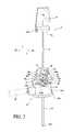
- FIG. 2is a partial cross-sectional view of the port access assembly of the instant invention with the needle shown having been withdrawn into the cap of the port access assembly;
- FIG. 3is another cross-sectional view of the interior cavity of the protective cap of the port access assembly of the instant invention showing the safety clip in a canted position;
- FIG. 4is a cross-sectional view of the port access assembly of the instant invention showing the cap coupled to the infuser;
- FIGS. 5 a - 5 dare respective views of the port access assembly of the instant invention shown in the various stages where the inserter is being withdrawn relative to the infuser.
- the portal or port access assembly of the instant inventionis shown to include an inserter 2 having a handle 4 and a needle or trocar 5 extending downwardly in a vertical direction from handle 4 along the longitudinal axis of the needle.
- Handle 4has a main portion 4 a and a lower portion 4 b that defines a bore 4 c.
- cap or housing 6Mounted about needle 5 and slidable relative to and movable along the length of needle 5 is a cap or housing 6 that has an upper circumferential turret portion 6 a and a semi-cone shaped lower portion 6 b .
- Cap 6has a top portion or top 6 t , and a bottom portion or bottom 6 l that is joined to or is integral with the distal bottom of lower portion 6 b .
- Tip 5 t of needle 5is shown to extend through an opening 10 at bottom 6 l and from there through infuser or infusion site 12 and the blunt cannula 14 that extends from the bottom or base 12 b of infuser 12 .
- handle 4is fittingly coupled to cap 6 as bore 4 c of lower portion 4 b of handle 4 removably mates to the upper turret portion 6 a of cap 6 .
- Infuser 12has a dome shaped housing 12 a that is in fluid communication with blunt cannula 14 . Fluid or medication may be conveyed into housing 12 a by a catheter tubing 16 , shown in dotted line in FIG. 2 , connected to infuser 12 .
- Infuser 12has a top or top portion 12 t and a bottom or base portion 12 b .
- a resealable septum 12 d( FIG. 4 ) that is pierceable by needle 5 may be fixed to the lower surface of top 12 a for example by gluing or bonding, so that as shown in FIG.
- needle 5extends through cap 6 and pierces through septum 12 d into infuser 12 , and from there extends through blunt cannula 14 , its distal sharp tip 5 t extending beyond the distal end of cannula 14 .
- a cavity 6 cis formed in the interior of cap 6 .
- a safety mechanismin the form of a clip 18 that has a first or upper leg 18 a and a second or lower leg 18 b that are joined by a bridge section 18 c that is substantially orthogonal to the two legs.
- section 18 cmay comprise two spaced in parallel members each connecting the two legs.
- Leg 18 bhas an edge 18 e , which is shown in FIG. 1 to be biased by the shaft of needle, as needle 5 extends from the upper opening 9 at the top of cap 6 through cavity 6 c to the lower opening 10 at the bottom of cap 6 .
- the bridge section 18 c of clip 18lies substantially in parallel to the longitudinal axis along which needle 5 vertically extends.
- the position of the port access assembly as shown in FIG. 1may be referred to as the ready to use state or position.
- needle 5may be moved vertically relative to cap 6 and infuser 12 , so long as edge 18 e of lower leg 18 b of clip 18 is being biased by the shaft of needle 5 .
- the shaft of needle 5is biased by finger 8 b of upright 8 integral to cap 6 while the shaft in turn biases against edge 18 e of the lower leg 18 b of clip 18 .
- a cliniciancan determine whether or not blunt cannula 14 has been successfully positioned into the implant port 20 , per shown in FIG. 1 , by looking at the fluid or blood flash from the port.
- the port access assembly of the instant inventionmay be placed by the clinician onto the area of the patient superposed over the port 20 that has been implanted into the patient so that the distal portion of cannula 14 including its distal end 14 t , with needle tip 5 t extending therefrom, may be inserted into port 20 .
- needle 5may be removed from cannula 14 .
- a resulting fluid pathis thus established between catheter tubing 16 , infuser 12 , cannula 14 and implanted port 20 , with the medication supplied into port 20 output to the patient by means of port tubing 20 a.
- needle 5is shown to have been removed from infuser 12 .
- the distal tip 5 t of needle 5has been moved vertically upwards in the direction indicated by directional arrow 22 so that edge 18 e of the lower leg 18 b no longer is biased by the shaft of needle 5 .
- a bias meanssuch as a spring or an elastic flexible member provided in cavity 6 c , identified by the bold arrow 24 in FIG. 3 for illustration purpose, applies a biasing force against bridge section 18 c of clip 18 , so that when edge 18 e of leg 18 b is no longer biased by the shaft of needle 5 , per shown in FIG. 1 , the force 24 against clip 18 would move clip 18 into the canted position as shown in FIGS. 2 and 3 .
- leg 18 bis positioned in the angled orientation as shown in FIGS. 2 and 3 , thereby acting as a stop to entrap tip 5 t of needle 5 and to prevent needle 5 from moving downwards, per indicated by directional arrow 26 , once the needle tip 5 t is trapped by leg 18 b.
- Lower leg 18 bhas an extension 18 b ′ that, once leg 18 is moved to its canted position, would coact against the top surface of bottom 6 l of cap 6 , so that the lower leg 18 b is prevented from returning to its ready to use position as shown in FIG. 1 . Accordingly, with clip 18 in the canted position as shown in FIGS. 2 and 3 , needle 5 is prevented from moving upwardly per directional arrow 22 and downwardly per directional arrow 26 , with tip 5 t being trapped by leg 18 b and its extension 18 b ′. Also, edge 18 e of leg 18 b comes into abutting contact with the underside of finger 8 a of upright 8 .
- FIG. 4there is shown at the bottom 6 l of cap 6 two fingers 28 a and 28 b extending downwardly adjacent to lower opening 10 of cap 6 . Fingers 28 a and 28 b engage with a circumferential groove 30 provided at the counterpart opening 32 at the top 12 t of infuser 12 . Fingers 28 a and 28 b may be considered as one lock mechanism and groove 30 and its upper protrusion 30 a may be considered as another lock mechanism.
- a through pathextends from cavity 6 c of cap 6 to cavity 12 c of infuser 12 , ignoring for the moment the presence of resealable septum 12 d bondedly affixed to the underside of top 12 t of infuser 12 .
- a through passageextends from cavity 12 c to cannula 14 , as is conventional for infusers.
- Needle 5in dotted line, is shown to extend from upper opening 9 at top 6 t of cap 6 to lower opening 10 at bottom 6 l of cap 6 , and extends into cavity 12 c of infuser 12 .
- the outer circumferential surface of needle 5biases against the interior wall 10 a of opening 10 , so that fingers 28 a and 28 b are held in place in groove 30 , resulting in cap 6 and infuser 12 being non-detachably coupled to each other.
- the removal of needle 5 by the pulling of handle 4 in the upwards direction relative to infuser 12also results the removal of cap 6 from infuser 12 , which is left on the patient, in one continuous vertical motion by the clinician. Medication may then be conveyed from infuser 12 to the implanted port 20 via cannula 14 .
- FIGS. 5 a - 5 dillustrate the different stages of the movement of the inserter relative to the infuser of the instant invention port access assembly.
- FIG. 5 ais similar to FIG. 1 in that the handle 4 of inserter 2 is shown to be coupled to cap 6 , which in turn rests on the top of infuser 12 , with needle 5 extending though cap 6 , infuser 12 and cannula 14 so that tip 5 t of needle 5 extends beyond the distal end of cannula 14 .
- cap 6is fixedly coupled to infuser 12 so that the port access assembly is in one piece.
- the one piece assemblycould then be readily positioned onto the area of the patient over the implanted port, so that only a simple vertical movement by the clinician is needed to insert the needle and cannula into the patient and position the cannula into the implanted port.
- the one piece port access assemblyallows the assembly to be shipped in the ready to use state.
- FIG. 5 bis similar to FIGS. 2 and 3 in that it shows that needle 5 has been removed from infuser 12 and that the tip of the needle is captured in place in cap 6 , by means of clip 18 , as shown per the cross-sectional view of cap 6 .
- FIG. 5 cis the same as FIG. 5 b except that it is in perspective view.
- FIG. 5 dshows the complete disengagement or removal of cap 6 from infuser 12 , with the tip of needle 5 being housed in cap 6 .
Landscapes
- Health & Medical Sciences (AREA)
- Life Sciences & Earth Sciences (AREA)
- Animal Behavior & Ethology (AREA)
- Engineering & Computer Science (AREA)
- Anesthesiology (AREA)
- Biomedical Technology (AREA)
- Heart & Thoracic Surgery (AREA)
- Hematology (AREA)
- General Health & Medical Sciences (AREA)
- Public Health (AREA)
- Veterinary Medicine (AREA)
- Vascular Medicine (AREA)
- Pulmonology (AREA)
- Biophysics (AREA)
- Infusion, Injection, And Reservoir Apparatuses (AREA)
Abstract
Description
Claims (9)
Priority Applications (5)
| Application Number | Priority Date | Filing Date | Title |
|---|---|---|---|
| US12/801,349US9011388B2 (en) | 2010-06-04 | 2010-06-04 | Passive safety portal device |
| TW100118274ATW201143834A (en) | 2010-06-04 | 2011-05-25 | Passive safety portal device |
| PCT/US2011/000999WO2011152871A2 (en) | 2010-06-04 | 2011-06-02 | Passive safety portal device |
| CN2011800276158ACN102905754A (en) | 2010-06-04 | 2011-06-02 | Passive Security Port Device |
| EP11790109.0AEP2575952A4 (en) | 2010-06-04 | 2011-06-02 | PASSIVE SAFETY PORT DEVICE |
Applications Claiming Priority (1)
| Application Number | Priority Date | Filing Date | Title |
|---|---|---|---|
| US12/801,349US9011388B2 (en) | 2010-06-04 | 2010-06-04 | Passive safety portal device |
Publications (2)
| Publication Number | Publication Date |
|---|---|
| US20110301542A1 US20110301542A1 (en) | 2011-12-08 |
| US9011388B2true US9011388B2 (en) | 2015-04-21 |
Family
ID=45065012
Family Applications (1)
| Application Number | Title | Priority Date | Filing Date |
|---|---|---|---|
| US12/801,349Expired - Fee RelatedUS9011388B2 (en) | 2010-06-04 | 2010-06-04 | Passive safety portal device |
Country Status (5)
| Country | Link |
|---|---|
| US (1) | US9011388B2 (en) |
| EP (1) | EP2575952A4 (en) |
| CN (1) | CN102905754A (en) |
| TW (1) | TW201143834A (en) |
| WO (1) | WO2011152871A2 (en) |
Cited By (8)
| Publication number | Priority date | Publication date | Assignee | Title |
|---|---|---|---|---|
| US11096582B2 (en) | 2018-11-20 | 2021-08-24 | Veris Health Inc. | Vascular access devices, systems, and methods for monitoring patient health |
| US11446434B2 (en) | 2019-02-22 | 2022-09-20 | Deka Products Limited Partnership | Infusion set and inserter assembly systems and methods |
| US11766550B2 (en) | 2017-05-21 | 2023-09-26 | Veris Health, Inc. | Implantable medication infusion port with physiologic monitoring |
| USD1013864S1 (en) | 2021-08-26 | 2024-02-06 | Deka Products Limited Partnership | Fluid administration apparatus assembly |
| USD1043976S1 (en) | 2022-08-26 | 2024-09-24 | Deka Products Limited Partnership | Fluid transfer connector |
| USD1057941S1 (en) | 2022-08-26 | 2025-01-14 | Deka Products Limited Partnership | Patient care assembly component |
| US12239811B2 (en) | 2018-11-20 | 2025-03-04 | Veris Health Inc. | Wireless charging, localization, and data communication for implantable vascular access devices |
| USD1090862S1 (en) | 2022-08-26 | 2025-08-26 | Deka Products Limited Partnership | Adhering assembly for medical devices and the like |
Families Citing this family (12)
| Publication number | Priority date | Publication date | Assignee | Title |
|---|---|---|---|---|
| US9358348B2 (en)* | 2006-06-14 | 2016-06-07 | Covidien Lp | Safety shield for medical needles |
| JP4994775B2 (en) | 2006-10-12 | 2012-08-08 | 日本コヴィディエン株式会社 | Needle point protector |
| ES2662356T3 (en) | 2011-04-27 | 2018-04-06 | Kpr U.S., Llc | Safety IV catheter assemblies |
| EP2760521B1 (en) | 2011-09-26 | 2016-01-06 | Covidien LP | Safety iv catheter and needle assembly |
| WO2013048975A1 (en) | 2011-09-26 | 2013-04-04 | Covidien Lp | Safety catheter |
| US8834422B2 (en) | 2011-10-14 | 2014-09-16 | Covidien Lp | Vascular access assembly and safety device |
| JP2013233247A (en)* | 2012-05-08 | 2013-11-21 | Nipro Corp | Indwelling needle assembly |
| SE537262C2 (en)* | 2012-06-15 | 2015-03-17 | Vigmed Ab | A closed IV catheter system comprising a needle guard device |
| FR3015297B1 (en)* | 2013-12-23 | 2018-03-16 | Vygon | INFUSION OR SECURE INJECTION DEVICE |
| JP6509915B2 (en)* | 2014-03-07 | 2019-05-08 | シー・アール・バード・インコーポレーテッドC R Bard Incorporated | Stabilization and guiding device for accessing embedded access port and related method |
| CN108498897A (en)* | 2018-04-12 | 2018-09-07 | 苏州林华医疗器械股份有限公司 | Venous transfusion port not damaged needle group and its application method |
| CN113456987B (en)* | 2021-05-31 | 2023-08-08 | 泰尔茂医疗产品(杭州)有限公司 | Introducer protection device, cannula part, cannula assembly and cannula device |
Citations (27)
| Publication number | Priority date | Publication date | Assignee | Title |
|---|---|---|---|---|
| US4000739A (en)* | 1975-07-09 | 1977-01-04 | Cordis Corporation | Hemostasis cannula |
| US4929241A (en) | 1988-08-05 | 1990-05-29 | Kulli John C | Medical needle puncture guard |
| US4944725A (en) | 1987-06-01 | 1990-07-31 | Mcdonald Michael | Safety needle apparatus |
| US4964854A (en) | 1989-01-23 | 1990-10-23 | Luther Medical Products, Inc. | Intravascular catheter assembly incorporating needle tip shielding cap |
| US4978344A (en) | 1988-08-11 | 1990-12-18 | Dombrowski Mitchell P | Needle and catheter assembly |
| US5300045A (en) | 1993-04-14 | 1994-04-05 | Plassche Jr Walter M | Interventional needle having an automatically capping stylet |
| US5322517A (en) | 1989-02-01 | 1994-06-21 | Sero-Guard Corporation | Disposable automatic hypodermic needle guard |
| US20020099339A1 (en)* | 2000-03-07 | 2002-07-25 | Volker Niermann | Passive safety device |
| US20030040724A1 (en)* | 1999-08-12 | 2003-02-27 | Lynn Lawrence A. | Luer receiving vascular access system |
| US6595954B1 (en) | 2000-03-13 | 2003-07-22 | Luther Research Partners, Llc | Insertion needle and soft catheter system with tip protector |
| US6613015B2 (en) | 2001-10-04 | 2003-09-02 | Deltec, Inc. | Right angle safety needle |
| US6719721B1 (en) | 2000-10-23 | 2004-04-13 | Elizabeth Okazaki | Safety port needle assembly |
| US20040133167A1 (en) | 2001-03-15 | 2004-07-08 | Ferguson F. Mark | Safety shield for medical needles |
| US20050004532A1 (en)* | 1997-08-20 | 2005-01-06 | Kevin Woehr | Protective device for an injection needle |
| US20050075609A1 (en) | 2003-10-01 | 2005-04-07 | Latona Patrick C. | Protective needle clips |
| US20050096592A1 (en)* | 2003-10-31 | 2005-05-05 | James Carlyon | Safety shield |
| US20050182363A1 (en)* | 2004-02-13 | 2005-08-18 | Kulli John C. | Needle tip protector |
| US20070149920A1 (en) | 2005-12-28 | 2007-06-28 | Smiths Medical Md, Inc. | Portal access device with removable sharps protection |
| US20070191771A1 (en) | 2006-02-14 | 2007-08-16 | Robert Moyer | Port access device |
| US7438703B2 (en) | 2000-12-08 | 2008-10-21 | Tyco Healthcare Group Lp | Safety shield for medical needles |
| US20090163861A1 (en)* | 2007-12-20 | 2009-06-25 | Tyco Healthcare Group Lp | Locking Clip Assembly With Spring-Loaded Collar |
| US7569033B2 (en) | 1998-07-31 | 2009-08-04 | Albany Medical College | Safety intravenous catheter assembly |
| US7597681B2 (en) | 2005-08-08 | 2009-10-06 | Smiths Medical Asd, Inc. | Needle guard mechanism with shroud |
| US7632243B2 (en) | 2005-08-08 | 2009-12-15 | Smiths Medical Asd, Inc. | Duckbill catheter release mechanism |
| US7988664B2 (en)* | 2004-11-01 | 2011-08-02 | Tyco Healthcare Group Lp | Locking clip with trigger bushing |
| US8109905B2 (en)* | 2001-10-24 | 2012-02-07 | Becton, Dickinson And Company | Retractable needle assembly |
| US8162889B2 (en)* | 2005-07-11 | 2012-04-24 | Covidien Ag | Safety reset key and needle assembly |
Family Cites Families (2)
| Publication number | Priority date | Publication date | Assignee | Title |
|---|---|---|---|---|
| US7753877B2 (en)* | 2005-08-08 | 2010-07-13 | Smiths Medical Asd, Inc. | Needle guard strut wall clip |
| CA2633773C (en)* | 2005-12-28 | 2015-04-14 | Smiths Medical Md, Inc. | Portal access device with removable sharps protection |
- 2010
- 2010-06-04USUS12/801,349patent/US9011388B2/ennot_activeExpired - Fee Related
- 2011
- 2011-05-25TWTW100118274Apatent/TW201143834A/enunknown
- 2011-06-02EPEP11790109.0Apatent/EP2575952A4/ennot_activeWithdrawn
- 2011-06-02WOPCT/US2011/000999patent/WO2011152871A2/enactiveApplication Filing
- 2011-06-02CNCN2011800276158Apatent/CN102905754A/enactivePending
Patent Citations (30)
| Publication number | Priority date | Publication date | Assignee | Title |
|---|---|---|---|---|
| US4000739A (en)* | 1975-07-09 | 1977-01-04 | Cordis Corporation | Hemostasis cannula |
| US4944725A (en) | 1987-06-01 | 1990-07-31 | Mcdonald Michael | Safety needle apparatus |
| US4929241A (en) | 1988-08-05 | 1990-05-29 | Kulli John C | Medical needle puncture guard |
| US4978344A (en) | 1988-08-11 | 1990-12-18 | Dombrowski Mitchell P | Needle and catheter assembly |
| US4964854A (en) | 1989-01-23 | 1990-10-23 | Luther Medical Products, Inc. | Intravascular catheter assembly incorporating needle tip shielding cap |
| US5322517A (en) | 1989-02-01 | 1994-06-21 | Sero-Guard Corporation | Disposable automatic hypodermic needle guard |
| US5300045A (en) | 1993-04-14 | 1994-04-05 | Plassche Jr Walter M | Interventional needle having an automatically capping stylet |
| US20050004532A1 (en)* | 1997-08-20 | 2005-01-06 | Kevin Woehr | Protective device for an injection needle |
| US7569033B2 (en) | 1998-07-31 | 2009-08-04 | Albany Medical College | Safety intravenous catheter assembly |
| US20030040724A1 (en)* | 1999-08-12 | 2003-02-27 | Lynn Lawrence A. | Luer receiving vascular access system |
| US20020099339A1 (en)* | 2000-03-07 | 2002-07-25 | Volker Niermann | Passive safety device |
| US6537259B1 (en)* | 2000-03-07 | 2003-03-25 | Becton, Dickinson And Company | Passive safety device |
| US6595954B1 (en) | 2000-03-13 | 2003-07-22 | Luther Research Partners, Llc | Insertion needle and soft catheter system with tip protector |
| US6719721B1 (en) | 2000-10-23 | 2004-04-13 | Elizabeth Okazaki | Safety port needle assembly |
| US7438703B2 (en) | 2000-12-08 | 2008-10-21 | Tyco Healthcare Group Lp | Safety shield for medical needles |
| US20040133167A1 (en) | 2001-03-15 | 2004-07-08 | Ferguson F. Mark | Safety shield for medical needles |
| US6613015B2 (en) | 2001-10-04 | 2003-09-02 | Deltec, Inc. | Right angle safety needle |
| US8109905B2 (en)* | 2001-10-24 | 2012-02-07 | Becton, Dickinson And Company | Retractable needle assembly |
| US20050075609A1 (en) | 2003-10-01 | 2005-04-07 | Latona Patrick C. | Protective needle clips |
| US20050096592A1 (en)* | 2003-10-31 | 2005-05-05 | James Carlyon | Safety shield |
| US20050182363A1 (en)* | 2004-02-13 | 2005-08-18 | Kulli John C. | Needle tip protector |
| US7988664B2 (en)* | 2004-11-01 | 2011-08-02 | Tyco Healthcare Group Lp | Locking clip with trigger bushing |
| US8162889B2 (en)* | 2005-07-11 | 2012-04-24 | Covidien Ag | Safety reset key and needle assembly |
| US7597681B2 (en) | 2005-08-08 | 2009-10-06 | Smiths Medical Asd, Inc. | Needle guard mechanism with shroud |
| US7632243B2 (en) | 2005-08-08 | 2009-12-15 | Smiths Medical Asd, Inc. | Duckbill catheter release mechanism |
| US20070149920A1 (en) | 2005-12-28 | 2007-06-28 | Smiths Medical Md, Inc. | Portal access device with removable sharps protection |
| US7510543B2 (en) | 2005-12-28 | 2009-03-31 | Smiths Medical Md, Inc. | Removable sharps device for accessing a portal reservoir |
| US7549976B2 (en) | 2005-12-28 | 2009-06-23 | Smiths Medical Md, Inc. | Portal access device with removable sharps protection |
| US20070191771A1 (en) | 2006-02-14 | 2007-08-16 | Robert Moyer | Port access device |
| US20090163861A1 (en)* | 2007-12-20 | 2009-06-25 | Tyco Healthcare Group Lp | Locking Clip Assembly With Spring-Loaded Collar |
Non-Patent Citations (2)
| Title |
|---|
| PCT International Search Report issued by the ISA/KR on Feb. 22, 2012. |
| Supplementary European Search Report in related EP application No. 11790109.0, mailing date Dec. 4, 2013 from the European Patent Office. |
Cited By (11)
| Publication number | Priority date | Publication date | Assignee | Title |
|---|---|---|---|---|
| US11766550B2 (en) | 2017-05-21 | 2023-09-26 | Veris Health, Inc. | Implantable medication infusion port with physiologic monitoring |
| US12343492B2 (en) | 2017-05-21 | 2025-07-01 | Veris Health, Inc. | Implantable medication infusion port with physiologic monitoring |
| US11096582B2 (en) | 2018-11-20 | 2021-08-24 | Veris Health Inc. | Vascular access devices, systems, and methods for monitoring patient health |
| US12232852B2 (en) | 2018-11-20 | 2025-02-25 | Verid Health Inc. | Vascular access devices, systems, and methods for monitoring patient health |
| US12239811B2 (en) | 2018-11-20 | 2025-03-04 | Veris Health Inc. | Wireless charging, localization, and data communication for implantable vascular access devices |
| US11446434B2 (en) | 2019-02-22 | 2022-09-20 | Deka Products Limited Partnership | Infusion set and inserter assembly systems and methods |
| US12324899B2 (en) | 2019-02-22 | 2025-06-10 | Deka Products Limited Partnership | Infusion set and inserter assembly systems and methods |
| USD1013864S1 (en) | 2021-08-26 | 2024-02-06 | Deka Products Limited Partnership | Fluid administration apparatus assembly |
| USD1043976S1 (en) | 2022-08-26 | 2024-09-24 | Deka Products Limited Partnership | Fluid transfer connector |
| USD1057941S1 (en) | 2022-08-26 | 2025-01-14 | Deka Products Limited Partnership | Patient care assembly component |
| USD1090862S1 (en) | 2022-08-26 | 2025-08-26 | Deka Products Limited Partnership | Adhering assembly for medical devices and the like |
Also Published As
| Publication number | Publication date |
|---|---|
| EP2575952A4 (en) | 2014-01-01 |
| CN102905754A (en) | 2013-01-30 |
| WO2011152871A2 (en) | 2011-12-08 |
| TW201143834A (en) | 2011-12-16 |
| WO2011152871A3 (en) | 2012-04-26 |
| EP2575952A2 (en) | 2013-04-10 |
| US20110301542A1 (en) | 2011-12-08 |
Similar Documents
| Publication | Publication Date | Title |
|---|---|---|
| US9011388B2 (en) | Passive safety portal device | |
| US6830562B2 (en) | Injector device for placing a subcutaneous infusion set | |
| US6676633B2 (en) | Intravascular administration set needle safety device | |
| US7850652B2 (en) | Insertion head for medical or pharmaceutical applications | |
| US7361159B2 (en) | Passive safety shield | |
| US20030109829A1 (en) | Injector device for placing a subcutaneous infusion set | |
| US8262618B2 (en) | System consisting of an insertion head and an inserter | |
| EP2155299B1 (en) | Delivery device | |
| EP2276537B1 (en) | Separatable infusion set with cleanable interface and straight line attachment | |
| US11980740B2 (en) | Stabilization and guide apparatus for access to an implanted access port and related methods | |
| CN103068309B (en) | Passively shielding needle assembly with skin sensor | |
| US20100004605A1 (en) | Percutaneous safety needle inserter | |
| JP2003516777A (en) | Reaccessible medical needle safety device and method | |
| KR20120026489A (en) | Iv catheter introducer | |
| JP2010524646A (en) | Method and apparatus for intradermal injection | |
| WO2007079114A2 (en) | Portal access device with removable sharps protection | |
| JP2011522671A (en) | Fluid flow control device with retractable cannula | |
| WO2012030663A9 (en) | Safety catheter | |
| US8882727B2 (en) | Needle having a safety device | |
| JP2021519631A (en) | IV catheter with retractable needle, laterally offset urging element, and needle retracting cavity | |
| CN113271991B (en) | Safety mechanism for huber needle assembly | |
| EP1968689B1 (en) | Portal access device with removable sharps protection | |
| RU2299745C2 (en) | Injection device for mounting set intended for hypodermic injection | |
| CN219071581U (en) | Safety butterfly needle for preventing accidental injury |
Legal Events
| Date | Code | Title | Description |
|---|---|---|---|
| AS | Assignment | Owner name:SMITHS MEDICAL MD, INC., MINNESOTA Free format text:ASSIGNMENT OF ASSIGNORS INTEREST;ASSIGNORS:SCHWARTZ, LORI;TRAVIS, RONALD G.;REEL/FRAME:024527/0368 Effective date:20100602 | |
| AS | Assignment | Owner name:SMITHS MEDICAL ASD, INC, MINNESOTA Free format text:ASSIGNMENT OF ASSIGNORS INTEREST;ASSIGNOR:SMITHS MEDICAL MD, INC;REEL/FRAME:026147/0150 Effective date:20090731 | |
| STCF | Information on status: patent grant | Free format text:PATENTED CASE | |
| MAFP | Maintenance fee payment | Free format text:PAYMENT OF MAINTENANCE FEE, 4TH YEAR, LARGE ENTITY (ORIGINAL EVENT CODE: M1551); ENTITY STATUS OF PATENT OWNER: LARGE ENTITY Year of fee payment:4 | |
| AS | Assignment | Owner name:WELLS FARGO BANK, NATIONAL ASSOCIATION, AS COLLATERAL AGENT, TEXAS Free format text:SECURITY AGREEMENT;ASSIGNOR:SMITHS MEDICAL ASD, INC.;REEL/FRAME:061179/0320 Effective date:20220815 | |
| FEPP | Fee payment procedure | Free format text:MAINTENANCE FEE REMINDER MAILED (ORIGINAL EVENT CODE: REM.); ENTITY STATUS OF PATENT OWNER: LARGE ENTITY | |
| LAPS | Lapse for failure to pay maintenance fees | Free format text:PATENT EXPIRED FOR FAILURE TO PAY MAINTENANCE FEES (ORIGINAL EVENT CODE: EXP.); ENTITY STATUS OF PATENT OWNER: LARGE ENTITY | |
| STCH | Information on status: patent discontinuation | Free format text:PATENT EXPIRED DUE TO NONPAYMENT OF MAINTENANCE FEES UNDER 37 CFR 1.362 | |
| FP | Lapsed due to failure to pay maintenance fee | Effective date:20230421 |