US9010956B1 - LED module with on-board reflector-baffle-trim ring - Google Patents
LED module with on-board reflector-baffle-trim ringDownload PDFInfo
- Publication number
- US9010956B1 US9010956B1US13/048,435US201113048435AUS9010956B1US 9010956 B1US9010956 B1US 9010956B1US 201113048435 AUS201113048435 AUS 201113048435AUS 9010956 B1US9010956 B1US 9010956B1
- Authority
- US
- United States
- Prior art keywords
- heat sink
- coupled
- mounting
- light module
- receiving hole
- Prior art date
- Legal status (The legal status is an assumption and is not a legal conclusion. Google has not performed a legal analysis and makes no representation as to the accuracy of the status listed.)
- Active, expires
Links
Images


Classifications
- F—MECHANICAL ENGINEERING; LIGHTING; HEATING; WEAPONS; BLASTING
- F21—LIGHTING
- F21V—FUNCTIONAL FEATURES OR DETAILS OF LIGHTING DEVICES OR SYSTEMS THEREOF; STRUCTURAL COMBINATIONS OF LIGHTING DEVICES WITH OTHER ARTICLES, NOT OTHERWISE PROVIDED FOR
- F21V21/00—Supporting, suspending, or attaching arrangements for lighting devices; Hand grips
- F21V21/02—Wall, ceiling, or floor bases; Fixing pendants or arms to the bases
- F21V21/04—Recessed bases
- F21V21/041—Mounting arrangements specially adapted for false ceiling panels or partition walls made of plates
- F—MECHANICAL ENGINEERING; LIGHTING; HEATING; WEAPONS; BLASTING
- F21—LIGHTING
- F21S—NON-PORTABLE LIGHTING DEVICES; SYSTEMS THEREOF; VEHICLE LIGHTING DEVICES SPECIALLY ADAPTED FOR VEHICLE EXTERIORS
- F21S8/00—Lighting devices intended for fixed installation
- F21S8/02—Lighting devices intended for fixed installation of recess-mounted type, e.g. downlighters
- F21S8/026—Lighting devices intended for fixed installation of recess-mounted type, e.g. downlighters intended to be recessed in a ceiling or like overhead structure, e.g. suspended ceiling
- F—MECHANICAL ENGINEERING; LIGHTING; HEATING; WEAPONS; BLASTING
- F21—LIGHTING
- F21V—FUNCTIONAL FEATURES OR DETAILS OF LIGHTING DEVICES OR SYSTEMS THEREOF; STRUCTURAL COMBINATIONS OF LIGHTING DEVICES WITH OTHER ARTICLES, NOT OTHERWISE PROVIDED FOR
- F21V17/00—Fastening of component parts of lighting devices, e.g. shades, globes, refractors, reflectors, filters, screens, grids or protective cages
- F21V17/06—Fastening of component parts of lighting devices, e.g. shades, globes, refractors, reflectors, filters, screens, grids or protective cages the fastening being onto or by the lampholder
- F—MECHANICAL ENGINEERING; LIGHTING; HEATING; WEAPONS; BLASTING
- F21—LIGHTING
- F21V—FUNCTIONAL FEATURES OR DETAILS OF LIGHTING DEVICES OR SYSTEMS THEREOF; STRUCTURAL COMBINATIONS OF LIGHTING DEVICES WITH OTHER ARTICLES, NOT OTHERWISE PROVIDED FOR
- F21V21/00—Supporting, suspending, or attaching arrangements for lighting devices; Hand grips
- F21V21/02—Wall, ceiling, or floor bases; Fixing pendants or arms to the bases
- F21V21/04—Recessed bases
- F21V21/041—Mounting arrangements specially adapted for false ceiling panels or partition walls made of plates
- F21V21/042—Mounting arrangements specially adapted for false ceiling panels or partition walls made of plates using clamping means, e.g. for clamping with panel or wall
- F21V21/044—Mounting arrangements specially adapted for false ceiling panels or partition walls made of plates using clamping means, e.g. for clamping with panel or wall with elastically deformable elements, e.g. spring tongues
- F21V21/046—Mounting arrangements specially adapted for false ceiling panels or partition walls made of plates using clamping means, e.g. for clamping with panel or wall with elastically deformable elements, e.g. spring tongues being tensioned by rotation of parts
- F—MECHANICAL ENGINEERING; LIGHTING; HEATING; WEAPONS; BLASTING
- F21—LIGHTING
- F21V—FUNCTIONAL FEATURES OR DETAILS OF LIGHTING DEVICES OR SYSTEMS THEREOF; STRUCTURAL COMBINATIONS OF LIGHTING DEVICES WITH OTHER ARTICLES, NOT OTHERWISE PROVIDED FOR
- F21V21/00—Supporting, suspending, or attaching arrangements for lighting devices; Hand grips
- F21V21/14—Adjustable mountings
- F—MECHANICAL ENGINEERING; LIGHTING; HEATING; WEAPONS; BLASTING
- F21—LIGHTING
- F21V—FUNCTIONAL FEATURES OR DETAILS OF LIGHTING DEVICES OR SYSTEMS THEREOF; STRUCTURAL COMBINATIONS OF LIGHTING DEVICES WITH OTHER ARTICLES, NOT OTHERWISE PROVIDED FOR
- F21V29/00—Protecting lighting devices from thermal damage; Cooling or heating arrangements specially adapted for lighting devices or systems
- F21V29/50—Cooling arrangements
- F21V29/502—Cooling arrangements characterised by the adaptation for cooling of specific components
- F21V29/505—Cooling arrangements characterised by the adaptation for cooling of specific components of reflectors
- F—MECHANICAL ENGINEERING; LIGHTING; HEATING; WEAPONS; BLASTING
- F21—LIGHTING
- F21V—FUNCTIONAL FEATURES OR DETAILS OF LIGHTING DEVICES OR SYSTEMS THEREOF; STRUCTURAL COMBINATIONS OF LIGHTING DEVICES WITH OTHER ARTICLES, NOT OTHERWISE PROVIDED FOR
- F21V29/00—Protecting lighting devices from thermal damage; Cooling or heating arrangements specially adapted for lighting devices or systems
- F21V29/50—Cooling arrangements
- F21V29/70—Cooling arrangements characterised by passive heat-dissipating elements, e.g. heat-sinks
- F21V29/74—Cooling arrangements characterised by passive heat-dissipating elements, e.g. heat-sinks with fins or blades
- F21V29/77—Cooling arrangements characterised by passive heat-dissipating elements, e.g. heat-sinks with fins or blades with essentially identical diverging planar fins or blades, e.g. with fan-like or star-like cross-section
- F—MECHANICAL ENGINEERING; LIGHTING; HEATING; WEAPONS; BLASTING
- F21—LIGHTING
- F21V—FUNCTIONAL FEATURES OR DETAILS OF LIGHTING DEVICES OR SYSTEMS THEREOF; STRUCTURAL COMBINATIONS OF LIGHTING DEVICES WITH OTHER ARTICLES, NOT OTHERWISE PROVIDED FOR
- F21V7/00—Reflectors for light sources
- F21V7/0066—Reflectors for light sources specially adapted to cooperate with point like light sources; specially adapted to cooperate with light sources the shape of which is unspecified
- F—MECHANICAL ENGINEERING; LIGHTING; HEATING; WEAPONS; BLASTING
- F21—LIGHTING
- F21V—FUNCTIONAL FEATURES OR DETAILS OF LIGHTING DEVICES OR SYSTEMS THEREOF; STRUCTURAL COMBINATIONS OF LIGHTING DEVICES WITH OTHER ARTICLES, NOT OTHERWISE PROVIDED FOR
- F21V21/00—Supporting, suspending, or attaching arrangements for lighting devices; Hand grips
- F21V21/02—Wall, ceiling, or floor bases; Fixing pendants or arms to the bases
- F21V21/04—Recessed bases
- F21V21/041—Mounting arrangements specially adapted for false ceiling panels or partition walls made of plates
- F21V21/042—Mounting arrangements specially adapted for false ceiling panels or partition walls made of plates using clamping means, e.g. for clamping with panel or wall
- F21V21/044—Mounting arrangements specially adapted for false ceiling panels or partition walls made of plates using clamping means, e.g. for clamping with panel or wall with elastically deformable elements, e.g. spring tongues
- F—MECHANICAL ENGINEERING; LIGHTING; HEATING; WEAPONS; BLASTING
- F21—LIGHTING
- F21Y—INDEXING SCHEME ASSOCIATED WITH SUBCLASSES F21K, F21L, F21S and F21V, RELATING TO THE FORM OR THE KIND OF THE LIGHT SOURCES OR OF THE COLOUR OF THE LIGHT EMITTED
- F21Y2101/00—Point-like light sources
- F—MECHANICAL ENGINEERING; LIGHTING; HEATING; WEAPONS; BLASTING
- F21—LIGHTING
- F21Y—INDEXING SCHEME ASSOCIATED WITH SUBCLASSES F21K, F21L, F21S and F21V, RELATING TO THE FORM OR THE KIND OF THE LIGHT SOURCES OR OF THE COLOUR OF THE LIGHT EMITTED
- F21Y2115/00—Light-generating elements of semiconductor light sources
- F21Y2115/10—Light-emitting diodes [LED]
Definitions
- the present inventionrelates generally to luminaires. More specifically, the invention relates to a light emitting diode (LED) module that is used in a recessed luminaire.
- LEDlight emitting diode
- LEDsoffer benefits over incandescent and fluorescent lights as sources of illumination. Such benefits include high energy efficiency and longevity. To produce a given output of light, LEDs consume less electricity than incandescent or fluorescent lights. Additionally, on average, LEDs last longer than incandescent or fluorescent lights before failing.
- the level of light a typical LED outputsdepends upon the amount of electrical current supplied to the LED and upon the operating temperature of the LED. That is, the intensity of light emitted by the LED changes according to electrical current and LED temperature. Operating temperature also impacts the usable lifetime of LEDs.
- LEDsAs a byproduct of converting electricity into light, LEDs generate heat and raise the operating temperature, resulting in efficiency degradation and premature failure.
- a heat management systemsuch as a heat sink, is used in conjunction with the LEDs to facilitate maintenance of proper LED operating temperatures.
- Conventional LED-based recessed luminairesinclude a housing and a conventional LED module that is coupled within the housing.
- the conventional LED moduleincludes a heat sink, a fastening device for facilitating coupling between the conventional LED module and the housing, and one or more LEDs.
- the housingincludes a cavity formed therein and an opening at one end. The housing is installed within and above an aperture formed in a support structure, such as a ceiling, and oriented such that the opening faces a desired illumination area, such as a room.
- a spaceis formed around and between the lower exterior portion of the housing and the perimeter of the aperture.
- the openingis positioned in substantially the same plane as a lower surface of the support structure; however, the opening can be positioned in a different plane, such as slightly above the lower surface of the support structure.
- the heat sinkis installed and fitted within the cavity of the housing, generally using one or more fastening devices, such as torsion springs, and substantially occupies the entirety of the diameter of the cavity to maximize its heat removal performance.
- the conventional LED moduleis designed to fit within a housing having an opening with a certain nominal diameter. For example, one conventional LED module is designed to fit within a housing having a six inch nominal diameter opening, while a different conventional LED module is designed to fit within a different housing having a five inch nominal diameter opening. Thus, the conventional LED module typically is not designed to flexibly fit within housings having differently sized nominal diameter openings.
- the LEDsare typically coupled to a substrate, which is in thermal communication with the heat sink. The LEDs emit light and are oriented in a manner such that the light is directed to the desired illumination area through the opening.
- Conventional LED-based recessed luminairescan also include a trim ring.
- the trim ringis positioned adjacent to the opening and covers the opening.
- the trim ringtypically is separably coupled to the heat sink or to a portion of the housing, generally by use of torsion springs, and is positioned so that at least a portion of the trim ring extends below the support structure and covers the space formed between the lower exterior portion of the housing and the support structure when viewed from an area below the support structure.
- the trim ringis thermally coupled to the heat sink; however, since the trim ring is separably coupled to either the heat sink or the housing, the amount of heat removal from the trim ring into the area below the support structure, or room area, is limited because the area of direct contact between the trim ring and the heat sink is reduced.
- Some conventional LED-based recessed luminairesalso include a reflector. The reflector typically is separably disposed within the heat sink and surrounds the LEDs. The reflector directs light emitted from the LEDs toward the opening.
- Conventional LED-based recessed luminaires having several separably coupled componentsincrease costs related to tooling costs and assembly costs.
- a light modulecan include a heat sink and one or more light sources.
- the heat sinkcan include an internal surface surrounding a heat sink cavity formed therein.
- the internal surfacecan include a mounting region, a reflector region, and a decorative region.
- the reflector regioncan extend from the perimeter of the mounting region to a distal end.
- the decorative regioncan extend from the distal end to a second distal end.
- the light sourcescan be coupled to the mounting region within the heat sink cavity.
- a light modulecan include a heat sink, one or more light sources, and at least one mounting pad.
- the heat sinkcan include an internal surface surrounding a heat sink cavity formed therein.
- the light sourcescan be coupled to a portion of the internal surface of the heat sink cavity.
- the mounting padcan be coupled circumferentially around a portion of the heat sink.
- Each mounting padcan include a coupling hole, a first locator, and a second locator.
- the second locatorcan be positioned closest to an interior portion of the heat sink.
- the first locatorcan be positioned between the second locator and the coupling hole.
- the light modulecan include a heat sink, one or more LED packages, and at least one mounting pad.
- the heat sinkcan include an internal surface surrounding a heat sink cavity formed therein.
- the internal surfacecan include a mounting region, a reflector region, and a decorative region.
- the reflector regioncan extend from the perimeter of the mounting region to a distal end.
- the decorative regioncan extend from the distal end to a second distal end.
- the LED packagecan be coupled to a portion of the internal surface of the heat sink cavity.
- the mounting padcan be disposed circumferentially around a portion of the heat sink.
- Each mounting padcan include a coupling hole, a first locator, and a second locator.
- the coupling hole, the first locator, and the second locatorare radially and linearly aligned with one another.
- the second locatorcan be positioned closest to an interior portion of the heat sink.
- the first locatorcan be positioned between the second locator and the coupling hole.
- FIG. 1Ais a perspective view of an LED module according to an exemplary embodiment of the present invention.
- FIG. 1Bis another perspective view of the LED module of FIG. 1A according to an exemplary embodiment of the present invention
- FIG. 1Cis another perspective view of the LED module of FIG. 1A having the lens and LED packages removed according to an exemplary embodiment of the present invention
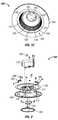
- FIG. 2is an exploded view of the LED module of FIG. 1A according to an exemplary embodiment of the present invention
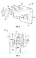
- FIG. 3is a perspective view of the mounting bracket capable of being used in the LED module of FIG. 2 according to an exemplary embodiment of the present invention
- FIG. 4is a partial perspective view of the heat sink capable of being used in the LED module of FIG. 2 illustrating the mounting pad according to an exemplary embodiment of the present invention
- FIG. 5is a partial perspective view of the LED module of FIG. 1A illustrating the mounting bracket of FIG. 3 coupled to the mounting pad of FIG. 4 according to an exemplary embodiment of the present invention.
- FIG. 6is an exploded view of an LED module according to another exemplary embodiment of the present invention.
- Exemplary embodiments of the present inventionare directed to luminaires.
- the term “luminaire,” as used herein,generally refers to a system for producing, controlling, and/or distributing light for illumination.
- a luminaireincludes a system that outputs or distributes light into an environment, thereby allowing certain items in that environment to be more visible.
- Such a systemcould be a complete lighting unit that includes one or more LEDs, or LED packages, for converting electrical energy into light, sockets, connectors, or receptacles for mechanically mounting and/or electrically connecting components to the system, optical elements for distributing light, and mechanical components for supporting or attaching the luminaire.
- Luminairesare sometimes referred to as “lighting fixtures” or as “light fixtures.”
- Luminairesare used in indoor or outdoor applications.
- FIGS. 1A , 1 B, and 1 Care various perspective views of an LED module 100 according to an exemplary embodiment of the present invention.
- the LED module 100includes a heat sink 110 , one or more chip on board LEDs 250 ( FIG. 2 ) thermally coupled to the heat sink 110 , and one or more torsion spring fastening devices 160 coupled to the heat sink 110 for coupling the LED module 100 to a housing (not shown).
- the housingis a recessed downlight can housing installed within a support structure (not shown), such as a ceiling.
- the LED module 100is positionable into a cavity (not shown) formed within the housing.
- the LED module 100also includes a driver 170 , a gasket 180 , and a lens 190 described in further detail below.
- the heat sink 110is formed as a single component and includes a first portion 111 , a second portion 121 positioned below the first portion 111 , one or more mounting pads 130 , a trim ring 140 , and a cavity 135 formed therein.
- the exemplary mounting pads 130are positioned at different circumferential positions around the second portion 121 .
- the exemplary trim ring 140extends radially outward from a second end 124 of the second portion 121 .
- the exemplary cavity 135is surrounded by an internal surface 139 of the heat sink 110 .
- the first portion 111extends a first longitudinal length 112 and includes one or more fins 118 .
- the fins 118extend from an interior portion 113 of the first portion 111 to an outer vertical periphery of the first portion 111 . These fins 118 are viewable from the exterior of the heat sink 110 according to certain exemplary embodiments. According to one exemplary embodiment, the fins 118 are integrally formed with the interior portion 113 during casting of the heat sink 110 . Alternatively, the fins 118 are coupled to the interior portion 113 of the first portion 111 subsequent to fabrication of the interior portion 113 using welding, fasteners or other methods known to people having ordinary skill in the art. According to one exemplary embodiment, the fins 118 extend substantially the entire first longitudinal length 112 .
- the fins 118extend a portion of the first longitudinal length 112 .
- one or more of the fins 118extend at least a portion of the first longitudinal length 112 and also extend along at least a portion of the outer perimeter of the second portion 121 .
- the fins 118extend substantially radially around the first portion 111 forming gaps 119 between adjacently positioned fins 118 .
- the fins 118extend substantially parallel to one another, also forming gaps 119 between adjacent fins 118 .
- These fins 118provide for an increase in exterior surface area of the first portion 111 , thereby allowing the first portion 111 to release more of the heat generated by the LED packages 250 ( FIG. 2 ) and/or the driver 170 .
- the first portion 111is fabricated using a thermally conductive, rigid material, such as a polymer, metal, or metal alloy.
- One example of the material used to fabricate the first portion 111is aluminum.
- the second portion 121is positioned generally below the first portion 111 and extends a second longitudinal length 122 .
- the second portion 121includes a first end 123 , a second end 124 , and a sidewall 125 .
- the first end 123has a smaller perimeter than the second end 124 .
- the first end 123has a perimeter that is equal to or greater than the second end 124 .
- the side wall 125extends from the first end 123 to the second end 124 .
- the second portion 121also includes a top surface 126 that is located at the first end 123 and between lower portions of adjacent fins 118 .
- the second end 124defines an opening 127 that extends within the heat sink 110 to form the cavity 135 therein.
- the second portion 121is integrally fabricated with the first portion 111 as a single component.
- the second portion 121is fabricated using a thermally conductive, rigid material, such as a polymer, metal, or metal alloy.
- a thermally conductive, rigid materialsuch as a polymer, metal, or metal alloy.
- One example of the material used to fabricate the second portion 121is aluminum.
- the mounting pads 130are substantially “L” shaped and extend along a portion of the top surface 126 in a raised manner. However, in alternative embodiments the mounting pads 130 are not raised. According to some exemplary embodiments, a portion of each mounting pad 130 also extends along at least a portion of the sidewall 125 . In one exemplary embodiment, four mounting pads 130 disposed circumferentially along the second portion 121 . However, in other exemplary embodiments, there are fewer or greater numbers of mounting pads 130 disposed circumferentially along the second portion 121 . These exemplary mounting pads 130 allow coupling the LED module 100 to the housing using the fastening devices 160 , which is described in further detail below with reference to FIGS. 3-5 .
- the mounting pads 130allow the LED module 100 to be inserted within and coupled to housings having differently sized cavities since the mounting pads 130 include a first locating hole and a second locating hole 452 , 453 ( FIG. 4 ) and the fastening devices 160 coupled to the LED module 100 are selectively positionable in either of these locating holes 452 , 453 ( FIG. 4 ) depending upon the size of the housing, which is discussed in further detail with respect to FIGS. 3-5 .
- the LED module 100is capable of being inserted within and coupled to a housing having a five-inch nominal diameter cavity and also to a housing having a six-inch nominal diameter cavity depending upon which of the first or second locating hole 452 , 453 ( FIG.
- the mounting pads 130are integrally fabricated with the first portion 111 and the second portion 121 as a single component and therefore are fabricated using the same material.
- the mounting pads 130are fabricated separately from the first portion 111 or the second portion 121 and thereafter coupled to at least one of the first portion 111 and/or the second portion 121 according to other exemplary embodiments.
- the mounting pads 130are fabricated using a thermally conductive, rigid material, such as a polymer, metal, or metal alloy.
- One example of the material used to fabricate the mounting pads 130is aluminum.
- the mounting pads 130are fabricated using any other suitable material, such as any thermally non-conductive material.
- the cavity 135is surrounded by the internal surface 139 which extends within the interior of the heat sink 110 .
- the cavity 135is formed during the casting process of the heat sink 110 according to certain exemplary embodiments. Alternatively, the cavity 135 is formed by machining into at least a portion of the second end 124 of the heat sink's second portion 121 , or by other methods known to people having ordinary skill in the art.
- the internal surface 139includes a mounting region 136 , a first region 137 , and a second region 138 .
- the mounting region 136is located within the first portion 111 of the heat sink 110 and is substantially planar according to some exemplary embodiments.
- the mounting region 136is oriented substantially parallel to the opening 127 and faces the desired illumination area. According to certain exemplary embodiments, the mounting region 136 is circular in shape. Alternatively, the mounting region 136 is shaped into other geometric or non-geometric shapes.
- the first region 137 and the second region 138collectively form a parabolic shape extending from the perimeter of the mounting region 136 to the perimeter of the opening 127 .
- the first region 137includes a proximal end 145 and a distal end 146 , wherein the diameter of the distal end 146 is greater than the diameter of the proximal end 145 .
- the diameter of the distal end 146is smaller than or equal to the diameter of the proximal end 145 in other exemplary embodiments.
- the proximal end 145is disposed around the perimeter of the mounting region 136 and the distal end 146 extends outwardly towards the opening 127 .
- the first region 137is fabricated to be reflective and facilitate directing light emitted from the LED packages 250 ( FIG. 2 ), which are coupled to the mounting region 136 , through the opening 127 .
- the surface of the first region 137is entirely smooth.
- the surface of the first region 137includes at least one of a faceted surface, a prismatic surface, and a dimpled surface.
- the first region 137is fabricated using the same material used for fabricating the first portion 111 , except that the first region 137 is made to be reflective if the first portion 111 is fabricated using non-reflective material.
- the first region 137is fabricated using a polished metal.
- the first region 137is fabricated using any suitable reflective material or any material capable of being made reflective, for example, a material capable of having white reflective paint adhered to its surface.
- the second region 138includes the distal end 146 of the first region and a second distal end 147 , wherein the diameter of the second distal end 147 is greater than the diameter of the distal end 146 . According to other exemplary embodiments, the diameter of the second distal end 147 is smaller than or equal to the diameter of the distal end 146 .
- the second distal end 147extends to the opening 127 and defines the opening 127 .
- the surface of the second region 138is baffled. In another example, the surface of the second region 138 is smooth. In yet another example, the surface of the second region 138 includes at least one of a faceted surface, a prismatic surface, a dimpled surface, and a painted surface.
- the second region 138is fabricated using the same material as that used to fabricate the first region 137 , but is finished similarly or differently than the finishing of the first region 137 depending upon design choices.
- the trim ring 140extends radially outward from the second end 124 of the heat sink's second portion 121 and includes a top surface 141 and a bottom surface 142 .
- the trim ring 140is typically positioned just below the plane of the opening 127 .
- the trim ring 140is integrally formed with the remaining portions of the heat sink 110 .
- the trim ring 140is fabricated using a thermally conductive material, such as a polymer, metal, or metal alloy.
- a thermally conductive materialsuch as a polymer, metal, or metal alloy.
- One example of the material used to fabricate the outer trim ring 140is aluminum.
- the heat transfer from the second portion 121 to the trim ring 140is improved because the trim ring 140 is always in constant contact around the entire circumference of the second portion 121 . At least a portion of the heat from the heat sink 110 is released into the desired illumination area using the pathway from the second portion 121 of the heat sink 110 to the trim ring 140 and to the desired illumination area.
- the heat sink 110is described as including several components, such as the first portion 111 , the second portion 121 , one or more mounting pads 130 , and the trim ring 140 .
- Each of the componentsare integrally formed with one another according to several exemplary embodiments; however, some exemplary embodiments have at least one component separately fabricated and thereafter coupled to the remaining portions of the integrally formed heat sink 110 .
- the fins 118are separately formed and thereafter coupled to the interior portion 113 of the first portion 111 according to some exemplary embodiments.
- the heat sink 110is fabricated using a thermally conductive, rigid material, such as a polymer, metal, or metal alloy.
- One example of the material used to fabricate the heat sink 110is aluminum.
- the material used to form some portions of the heat sink 110is finished differently than another portion of the heat sink 110 according to some exemplary embodiments.
- at least a portion of the internal surface's first region 137is polished to be made more reflective according to some exemplary embodiments.
- the exemplary LED module 100includes the driver 170 .
- the driver 170includes circuitry for controlling one or more LED packages 250 ( FIG. 2 ).
- the driver 170modifies the power entering the driver 170 through a power supply cable 175 to appropriately control at least a portion of the LED packages 250 ( FIG. 2 ).
- the driver 170controls the operation, color, and/or intensity of the light being emitted from the LED packages 250 ( FIG. 2 ).
- the power supply cable 175supplies power to the driver 170 from a power source (not shown).
- the power supply cable 175is fabricated using an insulative cover 176 surrounding one or more thermally conductive wires (not shown).
- the driver 170is thermally coupled to a portion of the heat sink 110 .
- the driver 170is thermally and directly coupled to the top portion of the heat sink's first portion 111 using coupling devices 202 ( FIG. 2 ), such as screws, nails, or rivets.
- the driver 170is thermally and indirectly coupled to the top portion of the heat sink's first portion 111 using thermal transference devices (not shown), such as heat pipes. The driver 170 emits heat which is transferred into the heat sink 110 .
- At least a portion of the heat generated from the driver 170is released into the desired illumination area using the pathway from the driver 170 , to the first portion 111 of the heat sink 110 , to the second portion 121 of the heat sink 110 , to the trim ring 140 , and to the desired illumination area.
- the LED module 100also includes one or more chip on board LEDs 250 ( FIG. 2 ).
- the LED packages 250are coupled, either directly or indirectly, to the mounting region 136 of the heat sink 110 .
- the LED packages 250are coupled to a substrate (not shown) which is then coupled to the mounting region 136 .
- the exemplary substrateincludes one or more sheets of ceramic, metal, laminate, circuit board, Mylar®, or another material and is coupled to the mounting region 136 of the heat sink 110 .
- Each LED package 250 ( FIG. 2 )includes a chip of semi-conductive material that is treated to create a positive-negative (“p-n”) junction.
- a power sourcesuch as the LED driver 170 , current flows from the positive side to the negative side of each junction, causing charge carriers to release energy in the form of incoherent light.
- the wavelength or color of the emitted lightdepends on the materials used to make the LED or LED package 250 ( FIG. 2 ).
- a blue or ultraviolet LEDtypically includes gallium nitride (“GaN”) or indium gallium nitride (“InGaN”)
- a red LEDtypically includes aluminum gallium arsenide (“AlGaAs”)
- a green LEDtypically includes aluminum gallium phosphide (“AlGaP”).
- Each of the LEDs in the LED package 250 ( FIG. 2 )can produce the same or a distinct color of light.
- the LED package 250FIG.
- the light emitted from the LEDsincludes one or more white LED's and one or more non-white LEDs, such as red, yellow, amber, or blue LEDs, for adjusting the color temperature output of the light emitted from the LED module 100 .
- a yellow or multi-chromatic phosphormay coat or otherwise be used in a blue or ultraviolet LED to create blue and red-shifted light that essentially matches blackbody radiation.
- the emitted lightapproximates or emulates “white,” incandescent light to a human observer.
- the emitted lightincludes substantially white light that seems slightly blue, green, red, yellow, orange, or some other color or tint.
- the light emitted from the LEDshas a color temperature between 2500 and 5000 degrees Kelvin.
- an optically transmissive or clear material(not shown) encapsulates at least a portion of each LED or LED package 250 ( FIG. 2 ).
- This encapsulating materialprovides environmental protection while transmitting light from the LEDs.
- the encapsulating materialincludes a conformal coating, a silicone gel, a cured/curable polymer, an adhesive, or some other material known to a person of ordinary skill in the art having the benefit of the present disclosure.
- phosphorsare coated onto or dispersed in the encapsulating material for creating white light.
- the white lighthas a color temperature between 2500 and 5000 degrees Kelvin.
- the LEDis an LED package 250 ( FIG. 2 ) that includes one or more arrays of LEDs that are collectively configured to produce a lumen output from 1 to 5000 lumens.
- the LEDs or the LED packages 250 ( FIG. 2 )are attached to the substrate by one or more solder joints, plugs, epoxy or bonding lines, and/or other means for mounting an electrical/optical device on a surface.
- the substrateis electrically connected to support circuitry (not shown) and/or the LED driver 170 for supplying electrical power and control to the LEDs or LED packages 250 ( FIG. 2 ).
- one or more wirescouple opposite ends of the substrate to the LED driver 170 , thereby completing a circuit between the LED driver 170 , substrate, and LED packages 250 ( FIG. 2 ).
- the LED driver 170is configured to separately control one or more portions of the LED packages 250 ( FIG. 2 ) in the array to adjust light color or intensity of the light that is emitted through the opening 127 .
- the LED packages 250( FIG. 2 ) emit heat which is transferred into the heat sink 110 .
- at least a portion of the heat generated from the LED packages 250 ( FIG. 2 )is released into the desired illumination area using the pathway from the LED packages 250 ( FIG. 2 ), to the mounting region 136 of the heat sink's first portion 111 , to the second portion 121 of the heat sink 110 , to the trim ring 140 , and to the desired illumination area.
- the exemplary LED module 100includes the gasket 180 .
- the exemplary gasket 180is ring-shaped and includes an inner perimeter 181 , and outer perimeter 182 , an upper surface 183 , and a lower surface (not shown). In alternative embodiments, the gasket 180 is shaped in other geometric or non-geometric shapes.
- the inner perimeter 181is substantially equal to or larger than the outer perimeter of the second portion's second end 124 .
- the outer perimeter 182is substantially equal to or smaller than the outer perimeter of the trim ring 140 .
- the gasket 180is typically disposed on the top surface 141 of the trim ring 140 such that the gasket's lower surface (not shown) is in contact with the trim ring's top surface 141 .
- the gasket 180is disposed between at least a portion of the trim ring's top surface 141 and the surface of the support structure.
- the exemplary gasket 180is fabricated using a foam material. However, other suitable materials, such as a rubber and other polymer materials, are suitable for manufacturing the gasket 180 in other exemplary embodiments.
- the exemplary LED module 100also includes the lens 190 .
- the lens 190is coupled to substantially the distal end 146 of the internal surface's first region 137 .
- the lens 190is coupled to the distal end 146 using clips (not shown).
- other devicessuch as screws or using the baffles as support, are used to couple the lens 190 in place.
- the lens 190is positioned either above or below the distal end 146 .
- the lens 190is fabricated using a transparent or translucent material, such as glass or plastic, which allows light generated from the LED packages 250 ( FIG. 2 ) to pass therethrough.
- the lens 190is tinted or milky colored to diffuse the light being emitted from the LED packages 250 , thereby avoiding an overly bright light source to be seen.
- the exemplary lens 190is smooth; however, alternative embodiments utilize a lens 190 that includes micro-patterns, dimples, and/or prismatic elements.
- the lens 190provides protection to the LED packages 250 ( FIG. 2 ) from dust and other contaminants.
- the exemplary lens 190is substantially concave-shaped having the concaved portion facing the LED packages 250 ( FIG. 2 ). In alternative embodiments, the lens 190 is shaped substantially planar, convexed, or some other shape.
- the exemplary LED module 100also includes fastening devices 160 adjustably coupled to the mounting pads 130 .
- the fastening devices 160in conjunction with the mounting pads 130 , facilitate the adjustable coupling of the LED module 100 into housings having different cavity diameter sizes.
- Each fastening device 160includes a mounting bracket 162 and a torsion spring 163 coupled to the mounting bracket 162 .
- Torsion springs 163are known to people having ordinary skill in the art and are used for coupling the LED module 100 to an interior wall surrounding the cavity formed within the housing (not shown).
- the torsion spring 163includes a ring portion 164 , a first rod 165 extending from the ring portion 164 in a first direction, and a second rod 166 extending from the ring portion 164 in a second direction.
- the fastening device 160is coupled to the mounting pad 130 using a coupling device 206 ( FIG. 2 ), such as a screw, being inserted through a portion of the mounting bracket 162 and into the mounting pad 130 .
- the fastening device 160 and the adjustable coupling of the fastening device 160 to the mounting pads 130are described in further detail below in conjunction with FIGS. 3-5 .
- FIG. 2is an exploded view of the LED module 100 according to an exemplary embodiment of the present invention.
- the heat sink 110is formed as a single integral component and includes the first portion 111 , the second portion 121 , the mounting pads 130 , and the trim ring 140 .
- the LED package 250is inserted into the cavity 135 formed within the heat sink 110 and is coupled to the mounting region 136 .
- the lens 190also is inserted into the cavity 135 and is coupled to the internal surface 139 at about the distal end 146 , located between the first region 137 and the second region 138 .
- the gasket 180is disposed on the trim ring 140 according to the description provided above.
- the fastening devices 160are coupled to the mounting pads 130 using coupling devices 206 , such as screws, according to the description provided above and further descriptions to be provided below.
- the driver 170is coupled to the top end of the heat sink's first portion 111 using coupling devices 202 according to the description provided above.
- FIG. 2illustrates several components being coupled together to form the LED module 100
- the LED module 100is formed using fewer components and/or additional components, such as a modular reflector 610 ( FIG. 6 ), according to other exemplary embodiments.
- FIG. 3is a perspective view of the mounting bracket 162 according to an exemplary embodiment of the present invention.
- FIG. 4is a partial perspective view of the heat sink 110 illustrating the mounting pad 130 according to an exemplary embodiment of the present invention.
- FIG. 5is a partial perspective view of the LED module 100 illustrating the mounting bracket 162 coupled to the mounting pad 130 according to an exemplary embodiment of the present invention. Referring to FIGS. 3-5 , the mounting bracket 162 is adjustably coupled to the mounting pad 130 and the torsion spring 163 is coupled to a portion of the mounting bracket 162 .
- the mounting bracket 162includes a first portion 310 , a second portion 320 , and a tab 330 .
- the second portion 320 and the tab 330each extend substantially perpendicular to the first portion 310 .
- the first portion 310 and second portion 320are substantially planar. Alternatively, one or both of the first 310 and second 320 portions is non-planar.
- the exemplary first portion 310extends longitudinally from a first end 312 to a second end 314 .
- the first portion 310includes a slot 316 that extends longitudinally along the first portion 310 and is positioned between the first end 312 and the second end 314 .
- the exemplary slot 316extends through the first portion 310 and is formed during the casting process of the mounting bracket 162 .
- the first portion 310also includes a lateral edge 311 extending downwardly from each of the longitudinal edges 309 of first portion's planar portion. The inner distance between each of the lateral edges 311 is slightly bigger than the width of the mounting pad 130 ( FIG. 4 ) to prevent the mounting bracket 162 from rotating or moving from side-to-side once couple to the respective mounting pad 130 ( FIG. 4 ).
- the second portion 320extends longitudinally from the first end 312 to an opposing end 322 .
- the second portion 320includes a torsion spring bracket 324 , which facilitates coupling the torsion spring 163 to the second portion 320 .
- the torsion spring bracket 324is formed by cutting through an interior portion of the second portion 320 and pushing a portion of the second portion 320 , which forms the torsion spring bracket 324 , into a different plane that is at an angle with the plane that the rest of the second portion 320 resides.
- the plane in which the torsion spring bracket 324 residesintersects with the first portion 310 according to some exemplary embodiments.
- the exemplary tab 330is substantially planar and extends longitudinally from a portion of the second end 314 to a distal end 332 . In certain exemplary embodiments, the tab 330 extends substantially from the middle of the second end 314 . The tab 330 extends in a plane that is substantially parallel to the plane of the second portion 320 .
- the exemplary mounting bracket 162is fabricated as a single component, but can alternatively be fabricated in several components and thereafter assembled together. The mounting bracket 162 is fabricated using a polymer material, metal, metal alloy, or other suitable materials known to people having ordinary skill in the art.
- the mounting pad 130includes a first portion 450 and a second portion 460 and, in certain exemplary embodiments, is positioned between two adjacent fins 118 .
- the first portion 450extends substantially along a portion of the top surface 126 in a raised and radial manner, while the second portion 460 is substantially perpendicular to the first portion 450 and extends from one end of the first portion 450 along at least a portion of the sidewall 125 .
- the first portion 450includes a first locating hole 452 and a second locating hole 453 , each dimensioned for receiving the tab 330 ( FIG. 3 ), and a coupling hole 454 that is dimensioned for receiving the coupling device 206 ( FIG. 2 ).
- each locating hole 452 , 453 and the coupling hole 454are linearly aligned, but can be non-linearly aligned in other exemplary embodiments.
- the first locating hole 452is positioned closest to the interior portion 113
- the coupling hole 454is positioned furthest from the interior portion 113
- the second locating hole 453is positioned between the first locating hole 452 and the coupling hole 454 .
- the locating holes 452 , 453 and the coupling hole 454are formed by machining through at least a portion of the mounting pad's first portion 450 .
- the exemplary locating holes 452 , 453 and coupling hole 454are circular.
- the locating holes 452 , 453 and/or the coupling hole 454are shaped in other geometric or non-geometric shapes.
- the centerpoint of each adjacent locating hole 452 , 453are distanced one inch apart. However, the distance is variable in other exemplary embodiments.
- the fastening device 160is assembled and coupled to the mounting pad 130 .
- the fastening device 160is assembled by snapping the torsion spring 163 onto the torsion spring bracket 324 .
- the ring portion 164is slid from the opposing end 322 of the mounting bracket's second portion 320 until the ring portion 164 snaps onto the torsion spring bracket 324 .
- other methods known to people having ordinary skill in the artcan be used to coupled the torsion spring 163 to the mounting bracket 162 .
- the fastening device 160is coupled to the mounting pad 130 by positioning the mounting bracket's first portion 310 above and substantially parallel to the mounting pad's first portion 450 and the mounting bracket's second portion 320 adjacent and substantially parallel to the mounting pad's second portion 460 .
- the tab 330is inserted into the second locating hole 453 and the coupling device 206 is inserted through the slot 316 and into the coupling hole 454 .
- a portion of the coupling device 206rests above the mounting bracket's first portion 310 , while a portion of the coupling device 206 is inserted and coupled within the coupling hole 454 .
- the LED module 100fits within a housing having a certain nominal diameter cavity. However, if the LED module 100 is to be fitted within a housing having a smaller nominal diameter cavity, the coupling device 206 is loosened so that the tab 330 is removed from the second locating hole 453 and moved into the first locating hole 452 . When moving the tab 330 from the second locating hole 453 to the first locating hole 452 , the mounting bracket 162 is moved closer to the interior portion 113 by sliding the coupling device 206 along the length of the slot 316 .
- the coupling device 206is securely re-coupled into the coupling hole 454 .
- the coupling device 206is removed when adjusting the position of the mounting bracket 162 .
- the LED module 100is capable of being installed within different housings having different nominal diameter cavities.
- bossesare formed in the same locations as the locating holes 452 , 453 and openings (not shown) are formed into the first portion 310 of the mounting bracket 162 such that at least one opening fits onto and surrounds one of the bosses.
- the bossesare formed to extend above the top surface of the mounting pad's first portion 450 .
- At least one openingis formed into the first portion 310 of the mounting bracket 162 and a portion of the heat sink 110 includes one or more receiving holes (not shown) such that the coupling device 206 couples the mounting bracket 162 to the heat sink 110 by being inserted into the receiving hole through the opening on the mounting bracket 162 .
- FIG. 4is an exploded view of an LED module 600 according to another exemplary embodiment of the present invention.
- LED module 600is similar to LED module 100 ( FIG. 2 ) except that LED module 600 includes the modular reflector 610 .
- the modular reflector 610is parabolic-shaped and has a proximal end 620 , a distal end 630 , and a sidewall 640 extending from the perimeter of the proximal end 620 to the perimeter of the distal end 630 .
- the proximal end 620has a smaller perimeter than the distal end 630 according to some exemplary embodiments; however, the proximal end 620 has a perimeter that is not smaller than the distal end 630 in other exemplary embodiments.
- the proximal end 620includes a proximal opening 622 that is dimensioned so that the proximal end 620 is installed within the cavity 135 ( FIG. 1C ) and is disposed around the LED package 250 once installed therein.
- the distal end 630forms a flange 632 that bends outwardly from the reflector 610 .
- the creation of the flange 632facilitates the coupling of the lens 190 to the distal end 630 of the reflector 610 .
- the exemplary parabolic-shaped reflector 610focuses the light emitted by the LED packages 250 to create a beam of light that is emitted to the desired illumination area.
- the sidewall 640 of the reflector 610includes an internal surface (not shown), which is reflective and smooth.
- the internal surfaceincludes at least one of facets, prismatic elements, and/or dimples around the internal surface.
- the reflector 610is fabricated using a reflective material or fabricated using a non-reflective material and subsequently made to be reflective by painting the internal surface with white reflective paint or other known methods.
Landscapes
- Engineering & Computer Science (AREA)
- General Engineering & Computer Science (AREA)
- Arrangement Of Elements, Cooling, Sealing, Or The Like Of Lighting Devices (AREA)
- Non-Portable Lighting Devices Or Systems Thereof (AREA)
Abstract
Description
Claims (11)
Priority Applications (6)
| Application Number | Priority Date | Filing Date | Title |
|---|---|---|---|
| US13/048,435US9010956B1 (en) | 2011-03-15 | 2011-03-15 | LED module with on-board reflector-baffle-trim ring |
| US14/690,188US9605842B1 (en) | 2011-03-15 | 2015-04-17 | LED module with mounting pads |
| US15/470,631US10378738B1 (en) | 2011-03-15 | 2017-03-27 | LED module with mounting brackets |
| US16/538,709US10527264B2 (en) | 2011-03-15 | 2019-08-12 | LED module with mounting brackets |
| US16/735,124US10677429B2 (en) | 2011-03-15 | 2020-01-06 | LED module with mounting brackets |
| US16/889,054US20200292156A1 (en) | 2011-03-15 | 2020-06-01 | Led module with mounting brackets |
Applications Claiming Priority (1)
| Application Number | Priority Date | Filing Date | Title |
|---|---|---|---|
| US13/048,435US9010956B1 (en) | 2011-03-15 | 2011-03-15 | LED module with on-board reflector-baffle-trim ring |
Related Child Applications (1)
| Application Number | Title | Priority Date | Filing Date |
|---|---|---|---|
| US14/690,188ContinuationUS9605842B1 (en) | 2011-03-15 | 2015-04-17 | LED module with mounting pads |
Publications (1)
| Publication Number | Publication Date |
|---|---|
| US9010956B1true US9010956B1 (en) | 2015-04-21 |
Family
ID=52822489
Family Applications (6)
| Application Number | Title | Priority Date | Filing Date |
|---|---|---|---|
| US13/048,435Active2034-01-19US9010956B1 (en) | 2011-03-15 | 2011-03-15 | LED module with on-board reflector-baffle-trim ring |
| US14/690,188ActiveUS9605842B1 (en) | 2011-03-15 | 2015-04-17 | LED module with mounting pads |
| US15/470,631ActiveUS10378738B1 (en) | 2011-03-15 | 2017-03-27 | LED module with mounting brackets |
| US16/538,709ActiveUS10527264B2 (en) | 2011-03-15 | 2019-08-12 | LED module with mounting brackets |
| US16/735,124ActiveUS10677429B2 (en) | 2011-03-15 | 2020-01-06 | LED module with mounting brackets |
| US16/889,054AbandonedUS20200292156A1 (en) | 2011-03-15 | 2020-06-01 | Led module with mounting brackets |
Family Applications After (5)
| Application Number | Title | Priority Date | Filing Date |
|---|---|---|---|
| US14/690,188ActiveUS9605842B1 (en) | 2011-03-15 | 2015-04-17 | LED module with mounting pads |
| US15/470,631ActiveUS10378738B1 (en) | 2011-03-15 | 2017-03-27 | LED module with mounting brackets |
| US16/538,709ActiveUS10527264B2 (en) | 2011-03-15 | 2019-08-12 | LED module with mounting brackets |
| US16/735,124ActiveUS10677429B2 (en) | 2011-03-15 | 2020-01-06 | LED module with mounting brackets |
| US16/889,054AbandonedUS20200292156A1 (en) | 2011-03-15 | 2020-06-01 | Led module with mounting brackets |
Country Status (1)
| Country | Link |
|---|---|
| US (6) | US9010956B1 (en) |
Cited By (35)
| Publication number | Priority date | Publication date | Assignee | Title |
|---|---|---|---|---|
| US20150252970A1 (en)* | 2012-03-23 | 2015-09-10 | Cree, Inc. | Led fixture with integrated driver circuitry |
| US20170045188A1 (en)* | 2014-04-24 | 2017-02-16 | Lg Innotek Co., Ltd. | Lighting device |
| US20170059139A1 (en) | 2015-08-26 | 2017-03-02 | Abl Ip Holding Llc | Led luminaire |
| US9777897B2 (en) | 2012-02-07 | 2017-10-03 | Cree, Inc. | Multiple panel troffer-style fixture |
| USD807556S1 (en) | 2014-02-02 | 2018-01-09 | Cree Hong Kong Limited | Troffer-style fixture |
| US9874322B2 (en) | 2012-04-10 | 2018-01-23 | Cree, Inc. | Lensed troffer-style light fixture |
| US9945533B1 (en)* | 2016-06-01 | 2018-04-17 | Cooper Technologies Company | Uniform lens illumination in downlight fixtures |
| WO2018098067A1 (en)* | 2016-11-22 | 2018-05-31 | Hubbell Incorporated | Lighting fixture for downlight with adjustable mounting bracket |
| US10012354B2 (en) | 2015-06-26 | 2018-07-03 | Cree, Inc. | Adjustable retrofit LED troffer |
| CN108895365A (en)* | 2018-04-19 | 2018-11-27 | 东莞市闻誉实业有限公司 | Pendant and pendant assembly |
| US20180372283A1 (en)* | 2017-06-27 | 2018-12-27 | Xiamen Eco Lighting Co. Ltd. | Downlight apparatus |
| US10228111B2 (en) | 2013-03-15 | 2019-03-12 | Cree, Inc. | Standardized troffer fixture |
| US10251279B1 (en) | 2018-01-04 | 2019-04-02 | Abl Ip Holding Llc | Printed circuit board mounting with tabs |
| US20190211998A1 (en)* | 2018-01-11 | 2019-07-11 | Xiamen Eco Lighting Co. Ltd. | Panel light fixture |
| US10451253B2 (en) | 2014-02-02 | 2019-10-22 | Ideal Industries Lighting Llc | Troffer-style fixture with LED strips |
| CN110529783A (en)* | 2019-10-08 | 2019-12-03 | 苏州荣文库柏照明系统股份有限公司 | A kind of downlight of adjustable installation dimension |
| US10527225B2 (en) | 2014-03-25 | 2020-01-07 | Ideal Industries, Llc | Frame and lens upgrade kits for lighting fixtures |
| US10544925B2 (en) | 2012-01-06 | 2020-01-28 | Ideal Industries Lighting Llc | Mounting system for retrofit light installation into existing light fixtures |
| US10563851B2 (en) | 2016-11-22 | 2020-02-18 | Hubbell Incorporated | LED circuit board layout for low profile lighting fixture |
| US10571112B2 (en) | 2014-11-07 | 2020-02-25 | Chm Industries, Inc. | Rotating light emitting diode high mast luminaire |
| US10591115B2 (en) | 2016-08-18 | 2020-03-17 | c2 Semiconductor, LLC | Retrofit kit and methods for conversion of fluorescent light assemblies to LED assemblies |
| US10648643B2 (en) | 2013-03-14 | 2020-05-12 | Ideal Industries Lighting Llc | Door frame troffer |
| USD886569S1 (en) | 2018-12-31 | 2020-06-09 | Luminii | Mounting bracket |
| US20200182452A1 (en)* | 2018-12-05 | 2020-06-11 | Light Emitting Design, Inc. | Heat dissipating led lighting fixture |
| USD899898S1 (en) | 2018-12-31 | 2020-10-27 | Luminii | Mounting bracket |
| US10816173B2 (en) | 2018-12-31 | 2020-10-27 | Luminii | Mounting brackets |
| US10823347B2 (en) | 2011-07-24 | 2020-11-03 | Ideal Industries Lighting Llc | Modular indirect suspended/ceiling mount fixture |
| US10823483B1 (en) | 2019-10-15 | 2020-11-03 | Haier Us Appliance Solutions, Inc. | Refrigerator appliance with heat transfer features for reducing condensation |
| US10883702B2 (en) | 2010-08-31 | 2021-01-05 | Ideal Industries Lighting Llc | Troffer-style fixture |
| US11047555B1 (en)* | 2020-08-10 | 2021-06-29 | Nathan YANG | Low profile light mounting assembly |
| US11221128B1 (en) | 2020-12-11 | 2022-01-11 | American Lighting, Inc. | Low profile downlight with trim ring |
| US20220325858A1 (en)* | 2021-04-06 | 2022-10-13 | Ch Lighting Technology Co., Ltd. | Recessed lamp and mounting structure thereof |
| US11530778B1 (en)* | 2022-01-14 | 2022-12-20 | Globe Electric Company Inc. | Light fixture mounting bracket assembly |
| US11665795B2 (en) | 2019-06-07 | 2023-05-30 | Hubbell Incorporated | Thermally protected low profile LED luminaire |
| US20250264213A1 (en)* | 2024-02-21 | 2025-08-21 | Hengdian Group Tospo Lighting Co., Ltd. | Spring-adjustable led light fixture and implementation method therefor |
Families Citing this family (52)
| Publication number | Priority date | Publication date | Assignee | Title |
|---|---|---|---|---|
| US10551044B2 (en) | 2015-11-16 | 2020-02-04 | DMF, Inc. | Recessed lighting assembly |
| US11435064B1 (en) | 2013-07-05 | 2022-09-06 | DMF, Inc. | Integrated lighting module |
| US11255497B2 (en) | 2013-07-05 | 2022-02-22 | DMF, Inc. | Adjustable electrical apparatus with hangar bars for installation in a building |
| US11060705B1 (en) | 2013-07-05 | 2021-07-13 | DMF, Inc. | Compact lighting apparatus with AC to DC converter and integrated electrical connector |
| US9964266B2 (en) | 2013-07-05 | 2018-05-08 | DMF, Inc. | Unified driver and light source assembly for recessed lighting |
| US10563850B2 (en) | 2015-04-22 | 2020-02-18 | DMF, Inc. | Outer casing for a recessed lighting fixture |
| US10753558B2 (en) | 2013-07-05 | 2020-08-25 | DMF, Inc. | Lighting apparatus and methods |
| US10591120B2 (en) | 2015-05-29 | 2020-03-17 | DMF, Inc. | Lighting module for recessed lighting systems |
| US10139059B2 (en) | 2014-02-18 | 2018-11-27 | DMF, Inc. | Adjustable compact recessed lighting assembly with hangar bars |
| USD851046S1 (en) | 2015-10-05 | 2019-06-11 | DMF, Inc. | Electrical Junction Box |
| US10295163B1 (en)* | 2017-03-20 | 2019-05-21 | Brandon Cohen | Lighting assembly with junction box support |
| USD892069S1 (en) | 2017-03-20 | 2020-08-04 | Brandon Cohen | Junction light box |
| WO2018237294A2 (en) | 2017-06-22 | 2018-12-27 | DMF, Inc. | THIN-PROFILE SURFACE MOUNTING LIGHTING DEVICE |
| US10488000B2 (en) | 2017-06-22 | 2019-11-26 | DMF, Inc. | Thin profile surface mount lighting apparatus |
| USD905327S1 (en) | 2018-05-17 | 2020-12-15 | DMF, Inc. | Light fixture |
| US11067231B2 (en) | 2017-08-28 | 2021-07-20 | DMF, Inc. | Alternate junction box and arrangement for lighting apparatus |
| US10648615B1 (en)* | 2017-11-03 | 2020-05-12 | Chatsworth Products Inc | Mounting system for wireless and sensing devices |
| CA3083359A1 (en) | 2017-11-28 | 2019-06-06 | DMF, Inc. | Adjustable hanger bar assembly |
| CA3087187A1 (en) | 2017-12-27 | 2019-07-04 | DMF, Inc. | Methods and apparatus for adjusting a luminaire |
| USD877957S1 (en) | 2018-05-24 | 2020-03-10 | DMF Inc. | Light fixture |
| WO2019241198A1 (en) | 2018-06-11 | 2019-12-19 | DMF, Inc. | A polymer housing for a recessed lighting system and methods for using same |
| USD903605S1 (en) | 2018-06-12 | 2020-12-01 | DMF, Inc. | Plastic deep electrical junction box |
| WO2020072592A1 (en) | 2018-10-02 | 2020-04-09 | Ver Lighting Llc | A bar hanger assembly with mating telescoping bars |
| US11280515B2 (en)* | 2019-01-09 | 2022-03-22 | Ascent Holdings, Llc | Ventilation fan trim ring mounting assembly |
| USD1012864S1 (en) | 2019-01-29 | 2024-01-30 | DMF, Inc. | Portion of a plastic deep electrical junction box |
| USD966877S1 (en) | 2019-03-14 | 2022-10-18 | Ver Lighting Llc | Hanger bar for a hanger bar assembly |
| US11725805B2 (en) | 2019-05-20 | 2023-08-15 | Amp Plus, Inc. | Lighting junction box with assembly for hanging |
| USD950824S1 (en) | 2019-08-02 | 2022-05-03 | Brandon Cohen | Integrated lighting module |
| US11219112B2 (en) | 2019-09-09 | 2022-01-04 | Appleton Grp Llc | Connected controls infrastructure |
| US11232684B2 (en) | 2019-09-09 | 2022-01-25 | Appleton Grp Llc | Smart luminaire group control using intragroup communication |
| WO2021051101A1 (en) | 2019-09-12 | 2021-03-18 | DMF, Inc. | Miniature lighting module and lighting fixtures using same |
| US11343898B2 (en) | 2019-09-20 | 2022-05-24 | Appleton Grp Llc | Smart dimming and sensor failure detection as part of built in daylight harvesting inside the luminaire |
| CN110566857B (en)* | 2019-10-08 | 2024-07-26 | 苏州荣文库柏照明系统股份有限公司 | Adjustable LED down lamp |
| US11224134B2 (en)* | 2019-11-14 | 2022-01-11 | Eaton Intelligent Power Limited | Electronic apparatus, circuit assembly, and associated method |
| US12196390B1 (en) | 2020-02-13 | 2025-01-14 | Brandon Cohen | Recessed lighting assembly and portions thereof |
| US12222084B2 (en) | 2020-02-13 | 2025-02-11 | Amp Plus, Inc. | Lighting junction box |
| US12228268B2 (en) | 2020-02-13 | 2025-02-18 | Amp Plus, Inc. | Lighting junction box |
| CA3124969A1 (en) | 2020-07-16 | 2022-01-16 | DMF, Inc. | Round metal housing for a lighting system |
| CA3124976A1 (en) | 2020-07-17 | 2022-01-17 | DMF, Inc. | Polymer housing for a lighting system and methods for using same |
| CA3124987A1 (en) | 2020-07-17 | 2022-01-17 | DMF, Inc. | Bar hanger assembly with crossmembers and housing assemblies using same |
| USD990030S1 (en) | 2020-07-17 | 2023-06-20 | DMF, Inc. | Housing for a lighting system |
| US11585517B2 (en) | 2020-07-23 | 2023-02-21 | DMF, Inc. | Lighting module having field-replaceable optics, improved cooling, and tool-less mounting features |
| USD927430S1 (en) | 2020-10-09 | 2021-08-10 | Brandon Cohen | Lighting junction box |
| US11466849B2 (en) | 2020-10-12 | 2022-10-11 | Brandon Cohen | Integrated lighting module |
| USD1087429S1 (en) | 2021-03-23 | 2025-08-05 | Amp Plus, Inc. | Light fixture |
| US11739893B2 (en) | 2021-03-23 | 2023-08-29 | Amp Plus, Inc. | Light fixture |
| USD1089782S1 (en) | 2021-03-23 | 2025-08-19 | Brandon Cohen | Light fixture |
| US11649954B2 (en) | 2021-04-30 | 2023-05-16 | Amp Plus, Inc. | Integrated lighting module and housing therefor |
| US11668458B2 (en) | 2021-06-30 | 2023-06-06 | Amp Plus, Inc. | Integrated lighting module |
| US11300259B1 (en) | 2021-06-30 | 2022-04-12 | Brandon Cohen | Downlight module with extendable lens |
| US12066175B2 (en) | 2021-11-09 | 2024-08-20 | Amp Plus, Inc. | Integrated lighting module |
| US12320501B2 (en) | 2022-04-20 | 2025-06-03 | Amp Plus, Inc. | Frame for lighting or junction box and I-bracket |
Citations (32)
| Publication number | Priority date | Publication date | Assignee | Title |
|---|---|---|---|---|
| US4142227A (en)* | 1977-05-23 | 1979-02-27 | Gulton Industries, Inc. | Combination passenger reading light and air ventilator |
| US4313154A (en) | 1980-05-08 | 1982-01-26 | Lightolier Incorporated | Lighting fixture with uniform mounting frame for new installations |
| US4399497A (en) | 1980-12-16 | 1983-08-16 | Prescolite | Retainer for a lamp |
| US4754377A (en) | 1986-02-21 | 1988-06-28 | Thomas Industries, Inc. | Thermally protected recessed lighting fixture |
| US6364511B1 (en) | 2000-03-31 | 2002-04-02 | Amp Plus, Inc. | Universal adapter bracket and ornamental trim assembly using same for in-ceiling recessed light fixtures |
| US6517218B2 (en) | 2000-03-31 | 2003-02-11 | Relume Corporation | LED integrated heat sink |
| US6554457B1 (en) | 2000-09-28 | 2003-04-29 | Juno Lighting, Inc. | System for lamp retention and relamping in an adjustable trim lighting fixture |
| US6787999B2 (en) | 2002-10-03 | 2004-09-07 | Gelcore, Llc | LED-based modular lamp |
| US20050174780A1 (en) | 2004-02-06 | 2005-08-11 | Daejin Dmp Co., Ltd. | LED light |
| US7102172B2 (en) | 2003-10-09 | 2006-09-05 | Permlight Products, Inc. | LED luminaire |
| US20070008716A1 (en)* | 2005-07-11 | 2007-01-11 | Glickman Mark F | Light fixture retrofitting apparatus and method |
| US7213940B1 (en) | 2005-12-21 | 2007-05-08 | Led Lighting Fixtures, Inc. | Lighting device and lighting method |
| US20070253202A1 (en) | 2006-04-28 | 2007-11-01 | Chaun-Choung Technology Corp. | LED lamp and heat-dissipating structure thereof |
| US7344279B2 (en) | 2003-12-11 | 2008-03-18 | Philips Solid-State Lighting Solutions, Inc. | Thermal management methods and apparatus for lighting devices |
| US7374308B2 (en) | 2004-10-25 | 2008-05-20 | Lloyd Sevack | Linear spring clip for securing lighting reflectors or housings into mounting frames |
| US20080130298A1 (en)* | 2006-11-30 | 2008-06-05 | Led Lighting Fixtures, Inc. | Self-ballasted solid state lighting devices |
| US20080304269A1 (en) | 2007-05-03 | 2008-12-11 | Cree Led Lighting Solutions, Inc. | Lighting fixture |
| US20090010007A1 (en)* | 2005-07-08 | 2009-01-08 | Canlyte, Inc. | Recessed Lighting Fixture |
| USD595005S1 (en) | 2008-05-20 | 2009-06-23 | Enertron, Inc. | Recessed can light fixture |
| US7597460B1 (en) | 2006-08-14 | 2009-10-06 | Hamid Rashidi | Tri-baffle ceiling fixture reflector including snapper assembly |
| US7658517B2 (en) | 2005-07-22 | 2010-02-09 | Genlyte Thomas Group, Llc | Hinged doors for recessed light fixture |
| USD610289S1 (en) | 2007-08-29 | 2010-02-16 | Toshiba Lighting & Technology Corporation | Recessed lighting fixture |
| US20100039829A1 (en) | 2008-08-12 | 2010-02-18 | Ge Investment Co., Ltd. | Light-emitting diode lamp |
| US20100061108A1 (en)* | 2007-10-10 | 2010-03-11 | Cordelia Lighting, Inc. | Lighting fixture with recessed baffle trim unit |
| US20100110699A1 (en) | 2007-09-27 | 2010-05-06 | Enertron, Inc. | Method and Apparatus for Thermally Effective Removable Trim for Light Fixture |
| US7722227B2 (en) | 2007-10-10 | 2010-05-25 | Cordelia Lighting, Inc. | Lighting fixture with recessed baffle trim unit |
| USD624691S1 (en) | 2009-12-29 | 2010-09-28 | Cordelia Lighting, Inc. | Recessed baffle trim |
| US7862214B2 (en) | 2006-10-23 | 2011-01-04 | Cree, Inc. | Lighting devices and methods of installing light engine housings and/or trim elements in lighting device housings |
| US7909487B1 (en)* | 2010-03-04 | 2011-03-22 | Keyser-Group | Lighting system and method of making same |
| USD636115S1 (en) | 2009-05-18 | 2011-04-12 | Osram Gesellschaft mit beschränkter Haftung | Recessed luminaire |
| USD636921S1 (en) | 2010-01-15 | 2011-04-26 | Cree, Inc. | Lighting device |
| USD638160S1 (en) | 2009-09-25 | 2011-05-17 | Cree, Inc. | Lighting device |
Family Cites Families (54)
| Publication number | Priority date | Publication date | Assignee | Title |
|---|---|---|---|---|
| US4910650A (en) | 1989-08-17 | 1990-03-20 | International Lighting Manufacturing Co. | Drop down diffuser frame for a ceiling light fixture |
| US5690423A (en) | 1996-03-04 | 1997-11-25 | Nsi Enterprises, Inc. | Wire frame pan assembly for mounting recessed lighting in ceilings and the like |
| US5673997A (en) | 1996-05-07 | 1997-10-07 | Cooper Industries, Inc. | Trim support for recessed lighting fixture |
| US5838247A (en) | 1997-04-01 | 1998-11-17 | Bladowski; Witold S. | Solid state light system |
| US6082878A (en) | 1998-02-03 | 2000-07-04 | Cooper Industries, Inc. | Fully rotatable recessed light fixture with movable stop and adjustable length bar hanger |
| US6095671A (en) | 1999-01-07 | 2000-08-01 | Hutain; Barry | Actively cooled lighting trim apparatus |
| US6367949B1 (en) | 1999-08-04 | 2002-04-09 | 911 Emergency Products, Inc. | Par 36 LED utility lamp |
| US6234643B1 (en) | 1999-09-01 | 2001-05-22 | Joseph F. Lichon, Jr. | Lay-in/recessed lighting fixture having direct/indirect reflectors |
| US6286265B1 (en) | 2000-02-01 | 2001-09-11 | Cooper Technologies Company | Recessed lighting fixture mounting |
| US6431723B1 (en) | 2000-04-28 | 2002-08-13 | Cooper Technologies, Company | Recessed lighting fixture |
| US6343873B1 (en) | 2000-04-28 | 2002-02-05 | Cooper Industries, Inc. | Lighting fixture with downlight reflector and wallwash reflector |
| US6283430B1 (en) | 2000-04-28 | 2001-09-04 | Cooper Technologies Company | Horizontal socket housing assembly |
| US6350043B1 (en) | 2000-07-21 | 2002-02-26 | Aerospace Lighting Corporation | Behind panel mount, directional lighting bracket |
| US6997583B2 (en) | 2002-05-10 | 2006-02-14 | Goodrich Hella Aerospace Lighting Systems Gmbh | Lamp for a vehicle, in particular reading lamp for an aircraft |
| US20070189001A1 (en) | 2002-12-11 | 2007-08-16 | Safeexits, Inc. | Multi-functional ballast and location-specific lighting |
| US6903380B2 (en) | 2003-04-11 | 2005-06-07 | Weldon Technologies, Inc. | High power light emitting diode |
| US20050169015A1 (en) | 2003-09-18 | 2005-08-04 | Luk John F. | LED color changing luminaire and track light system |
| US6982518B2 (en) | 2003-10-01 | 2006-01-03 | Enertron, Inc. | Methods and apparatus for an LED light |
| US20050168999A1 (en) | 2004-02-03 | 2005-08-04 | Gelcore Llc | LED light for loading dock |
| EP1600691A1 (en) | 2004-05-05 | 2005-11-30 | Lumodan ApS | Lamps and lamp assemblies |
| US7646029B2 (en) | 2004-07-08 | 2010-01-12 | Philips Solid-State Lighting Solutions, Inc. | LED package methods and systems |
| JP4989472B2 (en) | 2004-08-18 | 2012-08-01 | レムコ サリド ステイト ライティング インコーポレーテッド | LED control using dynamic resistance of LED |
| DE102004042186B4 (en) | 2004-08-31 | 2010-07-01 | Osram Opto Semiconductors Gmbh | Optoelectronic component |
| US7145179B2 (en) | 2004-10-12 | 2006-12-05 | Gelcore Llc | Magnetic attachment method for LED light engines |
| US7052171B1 (en) | 2004-12-15 | 2006-05-30 | Emteq, Inc. | Lighting assembly with swivel end connectors |
| US7726844B2 (en) | 2005-03-31 | 2010-06-01 | Neobulb Technologies, Inc. | Illuminating equipment using high power LED with high efficiency of heat dissipation |
| US7918591B2 (en) | 2005-05-13 | 2011-04-05 | Permlight Products, Inc. | LED-based luminaire |
| US20060262542A1 (en) | 2005-05-18 | 2006-11-23 | Jji Lighting Group, Inc. | Modular landscape light fixture |
| KR101343562B1 (en) | 2005-05-23 | 2013-12-23 | 필립스 솔리드-스테이트 라이팅 솔루션스, 인크. | Modular led-based lighting apparatus for socket engagement lighting fixtures incorporating same and methods of assembling installing and removing same |
| US7703951B2 (en) | 2005-05-23 | 2010-04-27 | Philips Solid-State Lighting Solutions, Inc. | Modular LED-based lighting fixtures having socket engagement features |
| US7766518B2 (en) | 2005-05-23 | 2010-08-03 | Philips Solid-State Lighting Solutions, Inc. | LED-based light-generating modules for socket engagement, and methods of assembling, installing and removing same |
| USD545988S1 (en)* | 2005-11-11 | 2007-07-03 | Zumtobel Lighting Gmbh & Co.Kg. | Light fixture |
| US7629570B2 (en) | 2005-11-26 | 2009-12-08 | Everbrite, Llc | LED lighting system for use in environments with high magnetics fields or that require low EMI emissions |
| JP2007234417A (en) | 2006-03-01 | 2007-09-13 | Compal Communications Inc | Light emitting diode module and its radiation fin device |
| US7821194B2 (en) | 2006-04-18 | 2010-10-26 | Cree, Inc. | Solid state lighting devices including light mixtures |
| WO2007142946A2 (en) | 2006-05-31 | 2007-12-13 | Cree Led Lighting Solutions, Inc. | Lighting device and method of lighting |
| DE202006009553U1 (en) | 2006-06-16 | 2006-08-31 | Chien, Chen-Chun, Sansia | Light-emitting diode module for vehicle headlamps, includes heat sink surrounding and dissipating heat from main body, with radial fins shaped to fit inside headlamp housing |
| KR200429206Y1 (en) | 2006-08-04 | 2006-10-18 | 주식회사 대진디엠피 | Purchase for LED |
| US7396146B2 (en) | 2006-08-09 | 2008-07-08 | Augux Co., Ltd. | Heat dissipating LED signal lamp source structure |
| US7766512B2 (en) | 2006-08-11 | 2010-08-03 | Enertron, Inc. | LED light in sealed fixture with heat transfer agent |
| CN101675298B (en) | 2006-09-18 | 2013-12-25 | 科锐公司 | Lighting device, lighting device combination, lamp and method of use thereof |
| US20080080188A1 (en) | 2006-09-29 | 2008-04-03 | Chin-Wen Wang | Modulized Assembly Of A Large-sized LED Lamp |
| US7677770B2 (en) | 2007-01-09 | 2010-03-16 | Lighting Science Group Corporation | Thermally-managed LED-based recessed down lights |
| JP4798504B2 (en) | 2007-01-31 | 2011-10-19 | 東芝ライテック株式会社 | lighting equipment |
| US7540761B2 (en) | 2007-05-01 | 2009-06-02 | Tyco Electronics Corporation | LED connector assembly with heat sink |
| CN101836042B (en) | 2007-09-21 | 2014-11-05 | 库帕技术公司 | Light emitting diode recessed light fixture |
| US7670021B2 (en) | 2007-09-27 | 2010-03-02 | Enertron, Inc. | Method and apparatus for thermally effective trim for light fixture |
| US7762829B2 (en) | 2007-12-27 | 2010-07-27 | Tyco Electronics Corporation | Connector assembly for termination of miniature electronics |
| US20090195159A1 (en) | 2008-02-03 | 2009-08-06 | Smith Jerry L | Led cooling system |
| US7866850B2 (en) | 2008-02-26 | 2011-01-11 | Journée Lighting, Inc. | Light fixture assembly and LED assembly |
| US7699505B2 (en) | 2008-04-15 | 2010-04-20 | Smart Electronics Works Co., Ltd. | Balloon lamp |
| US7784979B2 (en) | 2008-05-05 | 2010-08-31 | Cooper Technologies Company | Reflector assembly for a recessed luminaire |
| US20100002451A1 (en) | 2008-07-07 | 2010-01-07 | Reynolds Elaine M | Tinted and frosted outer bulb cover for lights |
| US8070328B1 (en) | 2009-01-13 | 2011-12-06 | Koninkliljke Philips Electronics N.V. | LED downlight |
- 2011
- 2011-03-15USUS13/048,435patent/US9010956B1/enactiveActive
- 2015
- 2015-04-17USUS14/690,188patent/US9605842B1/enactiveActive
- 2017
- 2017-03-27USUS15/470,631patent/US10378738B1/enactiveActive
- 2019
- 2019-08-12USUS16/538,709patent/US10527264B2/enactiveActive
- 2020
- 2020-01-06USUS16/735,124patent/US10677429B2/enactiveActive
- 2020-06-01USUS16/889,054patent/US20200292156A1/ennot_activeAbandoned
Patent Citations (33)
| Publication number | Priority date | Publication date | Assignee | Title |
|---|---|---|---|---|
| US4142227A (en)* | 1977-05-23 | 1979-02-27 | Gulton Industries, Inc. | Combination passenger reading light and air ventilator |
| US4313154A (en) | 1980-05-08 | 1982-01-26 | Lightolier Incorporated | Lighting fixture with uniform mounting frame for new installations |
| US4399497A (en) | 1980-12-16 | 1983-08-16 | Prescolite | Retainer for a lamp |
| US4754377A (en) | 1986-02-21 | 1988-06-28 | Thomas Industries, Inc. | Thermally protected recessed lighting fixture |
| US6364511B1 (en) | 2000-03-31 | 2002-04-02 | Amp Plus, Inc. | Universal adapter bracket and ornamental trim assembly using same for in-ceiling recessed light fixtures |
| US6517218B2 (en) | 2000-03-31 | 2003-02-11 | Relume Corporation | LED integrated heat sink |
| US6554457B1 (en) | 2000-09-28 | 2003-04-29 | Juno Lighting, Inc. | System for lamp retention and relamping in an adjustable trim lighting fixture |
| US6787999B2 (en) | 2002-10-03 | 2004-09-07 | Gelcore, Llc | LED-based modular lamp |
| US7102172B2 (en) | 2003-10-09 | 2006-09-05 | Permlight Products, Inc. | LED luminaire |
| US7344279B2 (en) | 2003-12-11 | 2008-03-18 | Philips Solid-State Lighting Solutions, Inc. | Thermal management methods and apparatus for lighting devices |
| US20050174780A1 (en) | 2004-02-06 | 2005-08-11 | Daejin Dmp Co., Ltd. | LED light |
| US7374308B2 (en) | 2004-10-25 | 2008-05-20 | Lloyd Sevack | Linear spring clip for securing lighting reflectors or housings into mounting frames |
| US20090010007A1 (en)* | 2005-07-08 | 2009-01-08 | Canlyte, Inc. | Recessed Lighting Fixture |
| US20070008716A1 (en)* | 2005-07-11 | 2007-01-11 | Glickman Mark F | Light fixture retrofitting apparatus and method |
| US20100085766A1 (en) | 2005-07-22 | 2010-04-08 | Genlyte Thomas Group Llc | Recessed Fixture with Hinged Doors and Rotatable Lamp |
| US7658517B2 (en) | 2005-07-22 | 2010-02-09 | Genlyte Thomas Group, Llc | Hinged doors for recessed light fixture |
| US7213940B1 (en) | 2005-12-21 | 2007-05-08 | Led Lighting Fixtures, Inc. | Lighting device and lighting method |
| US20070253202A1 (en) | 2006-04-28 | 2007-11-01 | Chaun-Choung Technology Corp. | LED lamp and heat-dissipating structure thereof |
| US7597460B1 (en) | 2006-08-14 | 2009-10-06 | Hamid Rashidi | Tri-baffle ceiling fixture reflector including snapper assembly |
| US7862214B2 (en) | 2006-10-23 | 2011-01-04 | Cree, Inc. | Lighting devices and methods of installing light engine housings and/or trim elements in lighting device housings |
| US20080130298A1 (en)* | 2006-11-30 | 2008-06-05 | Led Lighting Fixtures, Inc. | Self-ballasted solid state lighting devices |
| US20080304269A1 (en) | 2007-05-03 | 2008-12-11 | Cree Led Lighting Solutions, Inc. | Lighting fixture |
| USD610289S1 (en) | 2007-08-29 | 2010-02-16 | Toshiba Lighting & Technology Corporation | Recessed lighting fixture |
| US20100110699A1 (en) | 2007-09-27 | 2010-05-06 | Enertron, Inc. | Method and Apparatus for Thermally Effective Removable Trim for Light Fixture |
| US20100061108A1 (en)* | 2007-10-10 | 2010-03-11 | Cordelia Lighting, Inc. | Lighting fixture with recessed baffle trim unit |
| US7722227B2 (en) | 2007-10-10 | 2010-05-25 | Cordelia Lighting, Inc. | Lighting fixture with recessed baffle trim unit |
| USD595005S1 (en) | 2008-05-20 | 2009-06-23 | Enertron, Inc. | Recessed can light fixture |
| US20100039829A1 (en) | 2008-08-12 | 2010-02-18 | Ge Investment Co., Ltd. | Light-emitting diode lamp |
| USD636115S1 (en) | 2009-05-18 | 2011-04-12 | Osram Gesellschaft mit beschränkter Haftung | Recessed luminaire |
| USD638160S1 (en) | 2009-09-25 | 2011-05-17 | Cree, Inc. | Lighting device |
| USD624691S1 (en) | 2009-12-29 | 2010-09-28 | Cordelia Lighting, Inc. | Recessed baffle trim |
| USD636921S1 (en) | 2010-01-15 | 2011-04-26 | Cree, Inc. | Lighting device |
| US7909487B1 (en)* | 2010-03-04 | 2011-03-22 | Keyser-Group | Lighting system and method of making same |
Cited By (58)
| Publication number | Priority date | Publication date | Assignee | Title |
|---|---|---|---|---|
| US10883702B2 (en) | 2010-08-31 | 2021-01-05 | Ideal Industries Lighting Llc | Troffer-style fixture |
| US11306895B2 (en) | 2010-08-31 | 2022-04-19 | Ideal Industries Lighting Llc | Troffer-style fixture |
| US10823347B2 (en) | 2011-07-24 | 2020-11-03 | Ideal Industries Lighting Llc | Modular indirect suspended/ceiling mount fixture |
| US11209135B2 (en) | 2011-07-24 | 2021-12-28 | Ideal Industries Lighting Llc | Modular indirect suspended/ceiling mount fixture |
| US11408569B2 (en) | 2012-01-06 | 2022-08-09 | Ideal Industries Lighting Llc | Mounting system for retrofit light installation into existing light fixtures |
| US10544925B2 (en) | 2012-01-06 | 2020-01-28 | Ideal Industries Lighting Llc | Mounting system for retrofit light installation into existing light fixtures |
| US9777897B2 (en) | 2012-02-07 | 2017-10-03 | Cree, Inc. | Multiple panel troffer-style fixture |
| US20150252970A1 (en)* | 2012-03-23 | 2015-09-10 | Cree, Inc. | Led fixture with integrated driver circuitry |
| US10514139B2 (en)* | 2012-03-23 | 2019-12-24 | Ideal Industries, Llc | LED fixture with integrated driver circuitry |
| US9874322B2 (en) | 2012-04-10 | 2018-01-23 | Cree, Inc. | Lensed troffer-style light fixture |
| US10648643B2 (en) | 2013-03-14 | 2020-05-12 | Ideal Industries Lighting Llc | Door frame troffer |
| US10228111B2 (en) | 2013-03-15 | 2019-03-12 | Cree, Inc. | Standardized troffer fixture |
| USRE48620E1 (en) | 2014-02-02 | 2021-07-06 | Ideal Industries Lighting Llc | Troffer-style fixture |
| USRE49228E1 (en) | 2014-02-02 | 2022-10-04 | Ideal Industries Lighting Llc | Troffer-style fixture |
| US10451253B2 (en) | 2014-02-02 | 2019-10-22 | Ideal Industries Lighting Llc | Troffer-style fixture with LED strips |
| USD807556S1 (en) | 2014-02-02 | 2018-01-09 | Cree Hong Kong Limited | Troffer-style fixture |
| US10527225B2 (en) | 2014-03-25 | 2020-01-07 | Ideal Industries, Llc | Frame and lens upgrade kits for lighting fixtures |
| US10234090B2 (en)* | 2014-04-24 | 2019-03-19 | Lg Innotek Co., Ltd. | Lighting device |
| US20170045188A1 (en)* | 2014-04-24 | 2017-02-16 | Lg Innotek Co., Ltd. | Lighting device |
| US11473767B2 (en) | 2014-11-07 | 2022-10-18 | Chm Industries, Inc. | Rotating light emitting diode high mast luminaire |
| US10571112B2 (en) | 2014-11-07 | 2020-02-25 | Chm Industries, Inc. | Rotating light emitting diode high mast luminaire |
| US10012354B2 (en) | 2015-06-26 | 2018-07-03 | Cree, Inc. | Adjustable retrofit LED troffer |
| US10253956B2 (en) | 2015-08-26 | 2019-04-09 | Abl Ip Holding Llc | LED luminaire with mounting structure for LED circuit board |
| US20170059139A1 (en) | 2015-08-26 | 2017-03-02 | Abl Ip Holding Llc | Led luminaire |
| US9945533B1 (en)* | 2016-06-01 | 2018-04-17 | Cooper Technologies Company | Uniform lens illumination in downlight fixtures |
| US10591115B2 (en) | 2016-08-18 | 2020-03-17 | c2 Semiconductor, LLC | Retrofit kit and methods for conversion of fluorescent light assemblies to LED assemblies |
| US10788162B2 (en) | 2016-08-18 | 2020-09-29 | c2 Semiconductor, LLC | Retrofit kit and methods for conversion of fluorescent light assemblies to LED assemblies |
| CN110073137B (en)* | 2016-11-22 | 2021-12-21 | 胡贝尔公司 | Lighting fixing device with adjustable mounting bracket for down lamp and mounting method thereof |
| US10928048B2 (en) | 2016-11-22 | 2021-02-23 | Hubbell Incorporated | LED circuit board layout for low profile lighting fixture |
| WO2018098067A1 (en)* | 2016-11-22 | 2018-05-31 | Hubbell Incorporated | Lighting fixture for downlight with adjustable mounting bracket |
| US10240764B2 (en)* | 2016-11-22 | 2019-03-26 | Hubbell Incorporated | Lighting fixture for downlight with adjustable mounting bracket |
| US10563851B2 (en) | 2016-11-22 | 2020-02-18 | Hubbell Incorporated | LED circuit board layout for low profile lighting fixture |
| US11143391B2 (en) | 2016-11-22 | 2021-10-12 | Hubbell Incorporated | LED circuit board layout for low profile lighting fixture |
| CN110073137A (en)* | 2016-11-22 | 2019-07-30 | 胡贝尔公司 | The light fixture for downlight with adjustable mounting bracket |
| US10627058B2 (en)* | 2017-06-27 | 2020-04-21 | Xiamen Eco Lighting Co. Ltd. | Downlight apparatus |
| US20180372283A1 (en)* | 2017-06-27 | 2018-12-27 | Xiamen Eco Lighting Co. Ltd. | Downlight apparatus |
| US10251279B1 (en) | 2018-01-04 | 2019-04-02 | Abl Ip Holding Llc | Printed circuit board mounting with tabs |
| US10876715B2 (en)* | 2018-01-11 | 2020-12-29 | Xiamen Eco Lighting Co. Ltd. | Panel light fixture |
| US20190211998A1 (en)* | 2018-01-11 | 2019-07-11 | Xiamen Eco Lighting Co. Ltd. | Panel light fixture |
| CN108895365A (en)* | 2018-04-19 | 2018-11-27 | 东莞市闻誉实业有限公司 | Pendant and pendant assembly |
| US11536443B2 (en)* | 2018-12-05 | 2022-12-27 | Light Emitting Design, Inc. | Heat dissipating LED lighting fixture |
| US20200182452A1 (en)* | 2018-12-05 | 2020-06-11 | Light Emitting Design, Inc. | Heat dissipating led lighting fixture |
| USD886569S1 (en) | 2018-12-31 | 2020-06-09 | Luminii | Mounting bracket |
| US10816173B2 (en) | 2018-12-31 | 2020-10-27 | Luminii | Mounting brackets |
| USD899898S1 (en) | 2018-12-31 | 2020-10-27 | Luminii | Mounting bracket |
| US12069780B2 (en) | 2019-06-07 | 2024-08-20 | Progress Lighting, Llc | Thermally protected low profile LED luminaire |
| US11665795B2 (en) | 2019-06-07 | 2023-05-30 | Hubbell Incorporated | Thermally protected low profile LED luminaire |
| CN110529783A (en)* | 2019-10-08 | 2019-12-03 | 苏州荣文库柏照明系统股份有限公司 | A kind of downlight of adjustable installation dimension |
| US10823483B1 (en) | 2019-10-15 | 2020-11-03 | Haier Us Appliance Solutions, Inc. | Refrigerator appliance with heat transfer features for reducing condensation |
| US11047555B1 (en)* | 2020-08-10 | 2021-06-29 | Nathan YANG | Low profile light mounting assembly |
| US11221128B1 (en) | 2020-12-11 | 2022-01-11 | American Lighting, Inc. | Low profile downlight with trim ring |
| US11754236B2 (en)* | 2021-04-06 | 2023-09-12 | Ch Lighting Technology Co., Ltd. | Recessed LED lamp with spring mounting structure |
| US20220325858A1 (en)* | 2021-04-06 | 2022-10-13 | Ch Lighting Technology Co., Ltd. | Recessed lamp and mounting structure thereof |
| US11530778B1 (en)* | 2022-01-14 | 2022-12-20 | Globe Electric Company Inc. | Light fixture mounting bracket assembly |
| US20230228392A1 (en)* | 2022-01-14 | 2023-07-20 | Globe Electric Company Inc. | Light fixture mounting bracket assembly |
| US11859792B2 (en)* | 2022-01-14 | 2024-01-02 | Globe Electric Company Inc. | Light fixture mounting bracket assembly |
| US12281753B2 (en) | 2022-01-14 | 2025-04-22 | Globe Electric Company Inc. | Light fixture mounting bracket assembly |
| US20250264213A1 (en)* | 2024-02-21 | 2025-08-21 | Hengdian Group Tospo Lighting Co., Ltd. | Spring-adjustable led light fixture and implementation method therefor |
Also Published As
| Publication number | Publication date |
|---|---|
| US10378738B1 (en) | 2019-08-13 |
| US20190360669A1 (en) | 2019-11-28 |
| US10527264B2 (en) | 2020-01-07 |
| US20200141562A1 (en) | 2020-05-07 |
| US20200292156A1 (en) | 2020-09-17 |
| US9605842B1 (en) | 2017-03-28 |
| US10677429B2 (en) | 2020-06-09 |
Similar Documents
| Publication | Publication Date | Title |
|---|---|---|
| US10677429B2 (en) | LED module with mounting brackets | |
| US8403533B1 (en) | Adjustable LED module with stationary heat sink | |
| US10989861B2 (en) | Edgelit LED blade fixture | |
| US8646948B1 (en) | LED lighting fixture | |
| US9052093B2 (en) | LED lamp and heat sink | |
| US8038314B2 (en) | Light emitting diode troffer | |
| US8911121B2 (en) | Light emitting diode recessed light fixture | |
| US8894253B2 (en) | Heat transfer bracket for lighting fixture | |
| US9285082B2 (en) | LED lamp with LED board heat sink | |
| US9159521B1 (en) | LED area lighting optical system | |
| US20100208460A1 (en) | Luminaire with led illumination core | |
| US8469555B2 (en) | Multi-reflector optical system | |
| US9115870B2 (en) | LED lamp and hybrid reflector | |
| US11421830B2 (en) | Lens-fitted retrofit LED lamp system | |
| US8864339B2 (en) | Thermal solution for LED candelabra lamps |
Legal Events
| Date | Code | Title | Description |
|---|---|---|---|
| AS | Assignment | Owner name:COOPER TECHNOLOGIES COMPANY, TEXAS Free format text:ASSIGNMENT OF ASSIGNORS INTEREST;ASSIGNOR:DAVIS, JARED MICHAEL;REEL/FRAME:026057/0891 Effective date:20110314 | |
| FEPP | Fee payment procedure | Free format text:PAYOR NUMBER ASSIGNED (ORIGINAL EVENT CODE: ASPN); ENTITY STATUS OF PATENT OWNER: LARGE ENTITY | |
| STCF | Information on status: patent grant | Free format text:PATENTED CASE | |
| AS | Assignment | Owner name:COOPER LIGHTING, LLC, GEORGIA Free format text:ASSIGNMENT OF ASSIGNORS INTEREST;ASSIGNOR:COOPER TECHNOLOGIES COMPANY;REEL/FRAME:039180/0710 Effective date:20160711 | |
| IPR | Aia trial proceeding filed before the patent and appeal board: inter partes review | Free format text:TRIAL NO: IPR2017-01859 Opponent name:CORDELIA LIGHTING, INC. AND JIMWAY, INC. Effective date:20170726 | |
| MAFP | Maintenance fee payment | Free format text:PAYMENT OF MAINTENANCE FEE, 4TH YEAR, LARGE ENTITY (ORIGINAL EVENT CODE: M1551); ENTITY STATUS OF PATENT OWNER: LARGE ENTITY Year of fee payment:4 | |
| AS | Assignment | Owner name:EATON INTELLIGENT POWER LIMITED, IRELAND Free format text:ASSIGNMENT OF ASSIGNORS INTEREST;ASSIGNOR:COOPER LIGHTING, LLC;REEL/FRAME:047543/0585 Effective date:20171231 | |
| AS | Assignment | Owner name:SIGNIFY HOLDING B.V., NETHERLANDS Free format text:ASSIGNMENT OF ASSIGNORS INTEREST;ASSIGNOR:EATON INTELLIGENT POWER LIMITED;REEL/FRAME:052681/0475 Effective date:20200302 | |
| AS | Assignment | Owner name:SIGNIFY HOLDING B.V., NETHERLANDS Free format text:CORRECTIVE ASSIGNMENT TO CORRECT THE APPLICATION NUMBERS 12183490, 12183499, 12494944, 12961315, 13528561, 13600790, 13826197, 14605880, 15186648, RECORDED IN ERROR PREVIOUSLY RECORDED ON REEL 052681 FRAME 0475. ASSIGNOR(S) HEREBY CONFIRMS THE ASSIGNMENT;ASSIGNOR:EATON INTELLIGENT POWER LIMITED;REEL/FRAME:055965/0721 Effective date:20200302 | |
| MAFP | Maintenance fee payment | Free format text:PAYMENT OF MAINTENANCE FEE, 8TH YEAR, LARGE ENTITY (ORIGINAL EVENT CODE: M1552); ENTITY STATUS OF PATENT OWNER: LARGE ENTITY Year of fee payment:8 |