US9010470B2 - Wheelchair suspension - Google Patents
Wheelchair suspensionDownload PDFInfo
- Publication number
- US9010470B2 US9010470B2US12/900,548US90054810AUS9010470B2US 9010470 B2US9010470 B2US 9010470B2US 90054810 AUS90054810 AUS 90054810AUS 9010470 B2US9010470 B2US 9010470B2
- Authority
- US
- United States
- Prior art keywords
- frame
- tip
- wheelchair
- wheels
- drive
- Prior art date
- Legal status (The legal status is an assumption and is not a legal conclusion. Google has not performed a legal analysis and makes no representation as to the accuracy of the status listed.)
- Active, expires
Links
Images


Classifications
- A—HUMAN NECESSITIES
- A61—MEDICAL OR VETERINARY SCIENCE; HYGIENE
- A61G—TRANSPORT, PERSONAL CONVEYANCES, OR ACCOMMODATION SPECIALLY ADAPTED FOR PATIENTS OR DISABLED PERSONS; OPERATING TABLES OR CHAIRS; CHAIRS FOR DENTISTRY; FUNERAL DEVICES
- A61G5/00—Chairs or personal conveyances specially adapted for patients or disabled persons, e.g. wheelchairs
- A61G5/10—Parts, details or accessories
- A—HUMAN NECESSITIES
- A61—MEDICAL OR VETERINARY SCIENCE; HYGIENE
- A61G—TRANSPORT, PERSONAL CONVEYANCES, OR ACCOMMODATION SPECIALLY ADAPTED FOR PATIENTS OR DISABLED PERSONS; OPERATING TABLES OR CHAIRS; CHAIRS FOR DENTISTRY; FUNERAL DEVICES
- A61G5/00—Chairs or personal conveyances specially adapted for patients or disabled persons, e.g. wheelchairs
- A61G5/06—Chairs or personal conveyances specially adapted for patients or disabled persons, e.g. wheelchairs with obstacle mounting facilities, e.g. for climbing stairs, kerbs or steps
- A—HUMAN NECESSITIES
- A61—MEDICAL OR VETERINARY SCIENCE; HYGIENE
- A61G—TRANSPORT, PERSONAL CONVEYANCES, OR ACCOMMODATION SPECIALLY ADAPTED FOR PATIENTS OR DISABLED PERSONS; OPERATING TABLES OR CHAIRS; CHAIRS FOR DENTISTRY; FUNERAL DEVICES
- A61G5/00—Chairs or personal conveyances specially adapted for patients or disabled persons, e.g. wheelchairs
- A61G5/04—Chairs or personal conveyances specially adapted for patients or disabled persons, e.g. wheelchairs motor-driven
- A61G5/041—Chairs or personal conveyances specially adapted for patients or disabled persons, e.g. wheelchairs motor-driven having a specific drive-type
- A61G5/042—Front wheel drive
- A—HUMAN NECESSITIES
- A61—MEDICAL OR VETERINARY SCIENCE; HYGIENE
- A61G—TRANSPORT, PERSONAL CONVEYANCES, OR ACCOMMODATION SPECIALLY ADAPTED FOR PATIENTS OR DISABLED PERSONS; OPERATING TABLES OR CHAIRS; CHAIRS FOR DENTISTRY; FUNERAL DEVICES
- A61G5/00—Chairs or personal conveyances specially adapted for patients or disabled persons, e.g. wheelchairs
- A61G5/04—Chairs or personal conveyances specially adapted for patients or disabled persons, e.g. wheelchairs motor-driven
- A61G5/041—Chairs or personal conveyances specially adapted for patients or disabled persons, e.g. wheelchairs motor-driven having a specific drive-type
- A61G5/043—Mid wheel drive
- A—HUMAN NECESSITIES
- A61—MEDICAL OR VETERINARY SCIENCE; HYGIENE
- A61G—TRANSPORT, PERSONAL CONVEYANCES, OR ACCOMMODATION SPECIALLY ADAPTED FOR PATIENTS OR DISABLED PERSONS; OPERATING TABLES OR CHAIRS; CHAIRS FOR DENTISTRY; FUNERAL DEVICES
- A61G5/00—Chairs or personal conveyances specially adapted for patients or disabled persons, e.g. wheelchairs
- A61G5/10—Parts, details or accessories
- A61G5/1078—Parts, details or accessories with shock absorbers or other suspension arrangements between wheels and frame
- A—HUMAN NECESSITIES
- A61—MEDICAL OR VETERINARY SCIENCE; HYGIENE
- A61G—TRANSPORT, PERSONAL CONVEYANCES, OR ACCOMMODATION SPECIALLY ADAPTED FOR PATIENTS OR DISABLED PERSONS; OPERATING TABLES OR CHAIRS; CHAIRS FOR DENTISTRY; FUNERAL DEVICES
- A61G5/00—Chairs or personal conveyances specially adapted for patients or disabled persons, e.g. wheelchairs
- A61G5/10—Parts, details or accessories
- A61G5/1089—Anti-tip devices
- A61G2005/1078—
- A61G2005/1089—
- B—PERFORMING OPERATIONS; TRANSPORTING
- B60—VEHICLES IN GENERAL
- B60G—VEHICLE SUSPENSION ARRANGEMENTS
- B60G2300/00—Indexing codes relating to the type of vehicle
- B60G2300/24—Wheelchairs
- Y—GENERAL TAGGING OF NEW TECHNOLOGICAL DEVELOPMENTS; GENERAL TAGGING OF CROSS-SECTIONAL TECHNOLOGIES SPANNING OVER SEVERAL SECTIONS OF THE IPC; TECHNICAL SUBJECTS COVERED BY FORMER USPC CROSS-REFERENCE ART COLLECTIONS [XRACs] AND DIGESTS
- Y10—TECHNICAL SUBJECTS COVERED BY FORMER USPC
- Y10S—TECHNICAL SUBJECTS COVERED BY FORMER USPC CROSS-REFERENCE ART COLLECTIONS [XRACs] AND DIGESTS
- Y10S180/00—Motor vehicles
- Y10S180/907—Motorized wheelchairs
Definitions
- Wheelchairs and scootersare an important means of transportation for a significant portion of society. Whether manual or powered, these vehicles provide an important degree of independence for those they assist. However, this degree of independence can be limited if the wheelchair is required to traverse obstacles such as, for example, curbs that are commonly present at sidewalks, driveways, and other paved surface interfaces. This degree of independence can also be limited if the vehicle is required to ascend inclines or descend declines.
- the anti-tip wheelsare typically much smaller than the drive wheels and located both forward and rearward of the drive wheels.
- the present applicationdiscloses several embodiments of wheeled vehicles, such as wheelchairs, that are adapted to traverse obstacles.
- the wheeled vehiclesinclude a frame, drive wheels, front anti-tip wheels positioned in front of the drive wheels, and rear anti-tip wheels positioned behind the drive wheels.
- One exemplary vehicleincludes front anti-tip wheels supported by rigid arms that are fixed to the frame and drive assemblies that are independently suspended from the frame.
- Another exemplary vehicleincludes a linkage that links the front and rear anti-tip wheels, such that movement of one of the front anti-tip wheel or the rear anti-tip wheel relative to the frame causes movement of the other wheel relative to the frame.
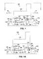
- FIG. 1is a side view of an exemplary embodiment of a wheelchair
- FIG. 1Ais a side view of a second configuration of the wheelchair of FIG. 1 ;
- FIG. 1Bis a side view of a third configuration of the wheelchair of FIG. 1 ;
- FIG. 1Cis a side view of a fourth configuration of the wheelchair of FIG. 1 ;
- FIG. 1Dis a side view of the wheelchair of FIG. 1 traversing an obstacle
- FIG. 2is a top view of the wheelchair shown in FIG. 1 ;
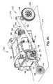
- FIG. 3Ais a side view of an exemplary embodiment of a wheelchair
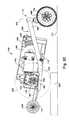
- FIG. 3Bis a side view of the wheelchair of FIG. 3A , with a drive wheel shown in schematically to more clearly illustrate a suspension assembly of the chassis;
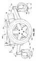
- FIG. 3Cis a perspective view of the wheelchair of FIG. 3B with a suspension assembly shown on one side of the chassis and the suspension assembly removed from the other side of the chassis
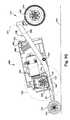
- FIG. 3Dshows a front anti-tip wheel of the chassis of FIG. 3B traversing an obstacle
- FIG. 3Eshows a drive wheel of the chassis of FIG. 3B traversing an obstacle
- FIG. 3Fshows a rear anti-tip wheel of the chassis of FIG. 3B traversing an obstacle
- FIG. 3Gshows the front anti-tip wheel of the chassis of FIG. 3B in engagement with a support surface to inhibit further tipping;
- FIG. 3His a perspective view of the wheelchair of FIG. 3C , with the drive assembly and drive wheel removed;
- FIG. 4Ais a side view of another embodiment of a wheelchair
- FIG. 4Bis a top view of the embodiment of the wheelchair shown in FIG. 4A ;
- FIG. 5is a side view of the wheelchair of FIG. 4A traversing an obstacle
- FIG. 6Ais a side view of another embodiment of a wheelchair
- FIG. 6Bis a top view of the embodiment of the wheelchair shown in FIG. 6A ;
- FIG. 7is a side view of the wheelchair of FIG. 6A traversing an obstacle
- FIG. 8Ais a side view of another embodiment of a wheelchair
- FIG. 8Bis a top view of the embodiment of the wheelchair shown in FIG. 8A ;
- FIG. 9is a side view of the wheelchair of FIG. 8A traversing an obstacle
- FIG. 10Ais a side view of another embodiment of a wheelchair
- FIG. 10Bis a top view of the embodiment of the wheelchair shown in FIG. 10A ;
- FIG. 11Ais a side view of another embodiment of a wheelchair
- FIG. 11Bis a top view of the embodiment of the wheelchair shown in FIG. 11A ;
- FIG. 12is a side view of the wheelchair of FIG. 11A traversing an obstacle
- FIG. 13Ais a side view of another embodiment of a wheelchair
- FIG. 13Bis a top view of the embodiment of the wheelchair shown in FIG. 13A ;
- FIG. 14Ais a side view of another embodiment of a wheelchair
- FIG. 14Bis a top view of the embodiment of the wheelchair shown in FIG. 14A ;
- FIG. 15is a schematic illustration of a pair of drive assemblies independently suspended from a wheelchair frame
- FIG. 16is a side view of another embodiment of a wheelchair.
- FIG. 16Ais a side view of a second configuration of the wheelchair of FIG. 16 ;
- FIG. 16Bis a side view of a third configuration of the wheelchair of FIG. 16 ;
- FIG. 16Cis a side view of a fourth configuration of the wheelchair of FIG. 16 ;
- FIG. 17is a top view of the wheelchair shown in FIG. 16 ;
- FIG. 18is a side view of the wheelchair of FIG. 16 traversing an obstacle
- FIG. 19Ais a side view of an exemplary embodiment of a wheelchair
- FIG. 19Bis a side view of the wheelchair of FIG. 19A , with a drive wheel shown schematically to more clearly illustrate a suspension assembly of the chassis;
- FIG. 19Cshows a front anti-tip wheel of the chassis of FIG. 19B traversing an obstacle
- FIG. 19Dshows a drive wheel of the chassis of FIG. 19B traversing an obstacle
- FIG. 19Eshows a rear anti-tip wheel of the chassis of FIG. 19B traversing an obstacle
- FIG. 19Fshows the front anti-tip wheel of the chassis of FIG. 19B in engagement with a support surface to inhibit further tipping;
- FIG. 20Ais a schematic illustration of a first embodiment of a variable length motion transfer arrangement coupled to components of a wheelchair suspension
- FIG. 20Bis a schematic illustration of a second embodiment of a variable length motion transfer arrangement coupled to components of a wheelchair suspension
- FIG. 20Cis a schematic illustration of a third embodiment of a variable length motion transfer arrangement coupled to components of a wheelchair suspension
- FIG. 21Ais a schematic illustration of an alternate embodiment of an of an anti-tip structure
- FIG. 21Bis a schematic illustration of an alternate embodiment of an of an anti-tip structure
- FIG. 22Ais a schematic illustration of an alternate embodiment of an of an anti-tip structure
- FIG. 22Bis a schematic illustration of an alternate embodiment of an of an anti-tip structure
- FIG. 23is a side view of another embodiment of a wheelchair.
- FIG. 23Ais a side view of another embodiment of a wheelchair
- FIG. 24is a top view of the wheelchair shown in FIG. 23 ;
- FIG. 25is a side view of the wheelchair of FIG. 23 traversing an obstacle
- FIG. 25Ais a side view of the wheelchair of FIG. 23A traversing an obstacle
- FIG. 26Ais a side view of an exemplary embodiment of a wheelchair.
- FIG. 26Bis a side view of the wheelchair of FIG. 26A , with a drive wheel removed to more clearly illustrate a suspension assembly of the chassis.
- the present patent application specification and drawingsprovide multiple embodiments of a vehicle, such as a wheelchair, and suspension that enhances the ability of the vehicle to traverse obstacles and/or improve the ride quality of the wheelchair.
- the illustrated embodiments of the vehiclesare wheelchairs, but the concepts of the illustrated embodiments are equally applicable to other types of vehicles.
- the wheelchairseach include a frame, a seat supported by the frame, a pair of drive assemblies, a pair of front anti-tip wheels, and at least one rear anti-tip wheel.
- the front anti-tip wheelsare connected to the frame, such that positions of axles of the front anti-tip wheels are fixed relative to the frame.
- the drive assembliesare moveable with respect to the frame and optionally with respect to one another.
- a linkagecouples a front anti-tip wheel to a rear anti-tip wheel such that movement of the front anti-tip wheel causes movement of the corresponding rear anti-tip wheel and/or vice versa.
- the linkagemay couple the front anti-tip wheel to the rear anti-tip wheel such that upward movement of the front anti-tip wheel relative to the frame causes upward movement of the rear anti-tip wheel relative to the frame.
- the linkagemay couple the front anti-tip wheel to the rear anti-tip wheel such that downward movement of the front anti-tip wheel relative to the frame causes downward movement of the rear anti-tip wheel relative to the frame.
- the term “frame”refers to any component or combination of components that are configured for coupling, mounting, attaching, or affixing of a drive assembly and at least one anti-tip wheel.
- the terms “couple,” “mount,” attach,” “affix,” “fix,” etc.are to be interpreted to include direct and indirect, through intermediate “coupling,” “mounting,” attaching,” “affixing,” “fixing,” etc.
- a component that is “fixed” to the framemay be directly connected to the frame or the component may be connected to the frame by one or more intermediate components that prevent relative movement of the component with respect to the frame.
- FIGS. 1 and 2illustrate a first embodiment of a wheelchair 100 .
- the wheelchair 100includes a frame 102 , a seat 103 supported by the frame, first and second drive assemblies 104 , 105 (see FIG. 2 ), first and second suspension assemblies 106 , 107 (see FIG. 2 ), first and second front anti-tip wheels 120 , 121 (see FIG. 2 ) and at least one rear anti-tip wheel 108 .
- the seat 103is shown schematically in FIGS. 1 and 2 and is omitted in the illustrations of many of the embodiments to indicate that any type of seat can be used. Also, seat 103 may face in either direction (i.e.
- the illustrated embodimentsmay be configured as front wheel drive wheelchairs or rear wheel drive wheelchairs.
- the wheelchair 100may be configured as a mid-wheel drive wheelchair. Any of the drive and suspension arrangements disclosed in this application may be used on front wheel drive wheelchairs, rear wheel drive wheelchairs, or mid wheel drive wheelchairs.
- the direction of forward travelmay be in the direction indicated by arrow 50 or in direction indicated by arrow 51 .
- the wheelchairmay include two separate drive assemblies. However, in other embodiments a single drive motor may drive both drive wheels.
- each drive assembly 104 , 105may be coupled to the frame by a corresponding suspension assembly 106 , 107 , such that each drive assembly is moveable relative to the frame 102 , and such that the drive assemblies are moveable relative to one another.
- the drive assembliesare moveable with respect to the frame, but are fixed or linked to one another.
- the suspension assemblies 106 , 107can take a wide variety of different fowls, several non-limiting examples of which are disclosed in detail below.
- the suspension assembly 106 , 107can be any arrangement that allows the drive assemblies 106 , 107 to move upward and/or downward relative to the frame.
- the terms “up”, “upward”, “down”, “downward”, “above” and “below” and any other directional termsrefer to the relative positions of the components when all of the wheels of the wheelchair are on a flat, level surface, such as support surface 119 illustrated in FIG. 1 .
- each drive assembly 104 , 105includes a drive motor 130 and a drive wheel 132 .
- the drive motor 130may comprise a motor/gear box combination, a brushless, gearless motor, or any other known arrangement for driving the drive wheel 132 .
- the drive motor 130drives the drive wheel 132 about the axis of rotation 112 .
- the at least one rear anti-tip wheel 108may take a wide variety of different forms. For example, there may be one, two, or any number of rear anti-tip wheels.
- Each rear anti-tip wheel 108may be a wheel of a caster assembly 170 which is rotatable about a substantially vertical axis 171 with the wheel 108 being rotatable about a substantially horizontal axis 174 .
- the wheel 108may be mounted for rotation only about a substantially horizontal axis 174 (i.e. there is no rotational connection at 171 ). In this alternative embodiment, the wheel 108 would typically, but not necessarily, be off the ground.
- two rear anti-tip wheels 108are disposed rearward of the drive wheels 132 .
- the rear anti-tip wheelsmay be disposed on the ground or spaced apart from a horizontal support surface when the wheelchair is at rest in a normal operating position on the horizontal support surface.
- the rear anti-tip wheelsmay include integral suspension elements, such as resilient spokes.
- two caster assemblies 170include anti-tip wheels 108 that are disposed on the horizontal support surface 119 when the wheelchair is in a normal operating position.
- the suspension assemblies 106 , 107are mirror images of one another. As such, only suspension assembly 106 is described in detail. In the illustrated embodiments, the suspension assemblies 106 , 107 are independently moveable relative to one another. However, the suspension assemblies 106 , 107 can be linked together, such that they move in unison, such that one assembly causes movement of the other assembly, or movement of one assembly is limited based on the position of the other assembly.
- the illustrated suspension assembly 106includes a pivot arm 134 and a biasing member 172 .
- the pivot arm 134is pivotally coupled to the frame 102 at a pivot axis 110 .
- the illustrated drive assembly 104is fixed to the pivot arm 134 .
- the drive assembly 104may be otherwise coupled to the pivot arm, such that movement of the pivot arm 134 causes movement of the drive assembly 104 relative to the frame 102 .
- the pivot arm 134may take a wide variety of different forms.
- the pivot arm 134may be any member that is pivotable with respect to the frame 102 to move the drive assembly 104 upward and downward with respect to the frame.
- the illustrated pivot arm 134includes a forward link 180 and a caster assembly 170 , which includes a rearward link 182 .
- the drive assembly 102is fixed to the forward link 180 and a rearward link 182 that supports the rear anti-tip wheel.
- the rear anti-tip wheel 108may be coupled to the rearward link 182 in any manner where movement of the pivot arm 134 causes movement of the rear anti-tip wheel 108 .
- the forward link 180 and the rearward link 182 of the pivot arm 134may be fixed relative to one another as indicated schematically by brace member 184 . It should be understood that no actual brace member 184 is required. Rather, the schematic brace member merely indicates any fixed connection between the forward link 180 and the rearward link 182 or that the links are integrally formed.
- the forward link 180 and the rearward link 182may be independent members that are pivotable about a common pivot axis or pivotable about two separate pivot axes (See FIGS. 4A and 4B ). When the forward link 180 and the rearward link 182 are not fixed together, they may optionally be coupled together by an extendable link 186 (See FIGS. 20A , 20 B, and 20 C), which would replace the fixed brace member.
- the axis 110can be positioned at a wide variety of different locations with respect to the frame 102 .
- the pivot axis 110can be positioned at any position on the frame or below the frame using with one or more brackets, etc.
- the drive assembly pivot axis 110 of the drive assembly 104is below an axis of rotation 112 of a drive axle 114 of the drive assembly 104 .
- the pivot arm 134may be a substantially rigid member that is connected to the motor drive 130 and the rear anti-tip wheel 108 .
- the pivot arm 134is flexible or one or more portions of the pivot arm are flexible to provide inherent shock absorbing properties in the pivot arm.
- the pivot arm 134may be made from a wide variety of materials, including, but not limited to, metals and plastics.
- the biasing member 172can take a wide variety of different forms. Any spring device, devices or assembly can be used as the biasing member.
- the biasing membermay be a single spring, a bi-directional spring, or multiple spring elements.
- the biasing membermay include a shock absorbing component, for example, the biasing member may be a shock absorber 2006 with a spring return (See FIG. 20C ).
- a spring mount 190is fixed to the frame 102 .
- the biasing member 172is disposed between the spring mount 190 and the pivot arm 134 .
- the biasing member 172 illustrated by FIG. 1is a compression spring that biases the rearward link 182 downward relative to the frame 102 as indicated by arrow 192 .
- An optional stop 194may be fixed to the frame to limit downward movement of the rearward link 182 with respect to the frame.
- the biasing memberis not fixed to the mount 190 or the pivot arm 134 .
- the biasing memberis connected to one or both of the mount 190 and the pivot arm 134 .
- FIGS. 1 , 1 A, 1 B and 1 Cillustrate that the biasing member 172 can be an extension spring or a compression spring positioned at a variety of different locations to provide the upward drive assembly/downward rearward link 182 biasing.
- the biasing member 172is an extension spring positioned below the rearward link 182 .
- the biasing member 172is an extension spring positioned above the forward link 180 .
- the biasing member 172is a compression spring positioned below the forward link 180 .
- the biasing member 172is configured to bias the forward link 180 downward and rearward link 182 upward. This can be accomplished in a variety of different ways. For example, in the examples illustrated by FIGS. 1 and 1C , the biasing member 172 can be changed from a compression spring to an extension spring and, in the examples illustrated by FIGS. 1A and 1B , the biasing member 172 can be changed from an extension spring to a compression spring. In another embodiment, the biasing member 172 is configured to bias the pivot arm 134 to a home position, such as the position relative to the frame illustrated by FIG. 1 . Biasing to a home position can be accomplished in a variety of different ways.
- a bidirectional springcan be coupled to the pivot arm and/or any one or more of the spring arrangements that bias the rear link 182 downward can be used with any one or more of the spring arrangements that bias the forward link 180 downward.
- the biasing memberis configured such that the drive wheel 132 and the rear anti-tip wheel 108 engage the horizontal support surface 119 when the wheelchair is at rest on the horizontal support surface.
- the first and second front anti-tip wheels 120 , 121may take a wide variety of different forms.
- the wheels 120 , 121may be wheels of caster assemblies (see for example, rear caster assemblies 170 ) or the wheels may be mounted for rotation only about a substantially horizontal axis 173 , as in the embodiment illustrated by FIG. 1 .
- the first and second front anti-tip wheels 120 , 121are located forward of the drive wheels 132 .
- the front anti-tip wheels 120 , 121may be disposed on the horizontal support surface 119 or spaced apart from the horizontal support surface 119 when the wheelchair is at rest or in a normal operating position, as in the embodiment illustrated by FIG. 1 .
- the front anti-tip wheels 120 , 121may include integral suspension elements, such as resilient spokes.
- the first and second front anti-tip wheels 120 , 121are supported by first and second arms 191 that are coupled to the frame 102 .
- the arms 191are fixedly connected to the frame.
- the arms 191may be suspended from the frame such that the arms are moveable with respect to the frame.
- the arms 191may be pivotally connected to the frame (See for example arm 1790 in FIG. 16C ) and/or coupled to the frame for translational movement relative to the frame (See for example coupling 806 in FIG. 8A ).
- the first and second arms 191may take a wide variety of different forms.
- the arms 191may be rigid or substantially rigid.
- the arms 191are flexible to provide inherent shock absorbing properties in the arm.
- the arms 191may be made from a wide variety of materials, including, but not limited to, metals and plastics.
- the arms 191are rigid.
- An axle that defines the axis of rotation 173 of each of the front anti-tip wheels 120 , 121is connected to each of the arms.
- the front anti-tip wheels 120 , 121are connected to the arms 191 such that positions of axes of rotation 173 of the front anti-tip wheels with respect to the frame 102 are fixed.
- the front anti-tip idler wheels 120 , 121are spaced apart from the horizontal support surface 119 when the wheelchair is at rest or in the normal operating position on the horizontal support surface 119 .
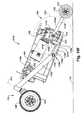
- FIGS. 3A-3Hillustrate a more specific embodiment of the wheelchair 100 illustrated by FIGS. 1 and 2 . It should be understood that the present application is not limited to the more specific embodiment illustrated by FIGS. 3A-3H .
- FIG. 3Aillustrates the wheelchair 100 at rest in the normal operating position on the horizontal support surface 119 .
- FIG. 3Billustrates the wheelchair of FIG. 3A with the drive wheel 132 schematically illustrated to more clearly illustrate the suspension 106 .
- FIGS. 1 D and 3 D- 3 Gillustrate operation of the wheelchair 100 . More specifically, these views are elevational views that illustrate embodiments of the wheelchair 100 traversing over an obstacle 300 by ascending the obstacle.
- the drive wheels 132bring the front anti-tip wheels 120 , 121 into engagement with the obstacle 300 .
- the drive wheels 132force the anti-tip wheels 120 , 121 up and onto the obstacle.
- the drive wheels 132remain on the ground and the upward movement (indicated by arrow 302 ) of the front anti-tip wheels 120 , 121 causes the frame 102 to rotate (indicated by arrow 304 ) about the pivot axis 110 of the suspensions 106 , 107 .
- the rotation 304 of the frame 102 relative to the pivot axiscauses compression (indicated by arrows 306 ) of the biasing member 172 .
- additional downward forceis applied to the rear anti-tip wheel 108 .
- the drive wheels 132continue to drive the wheelchair 100 forward.
- the drive wheels 132engage and climb over the obstacle 300 .
- the biasing member 172forces the rear anti-tip wheel 108 down.
- the drive wheels 132move the wheelchair 100 further forward on the obstacle 300 .
- the rear anti-tip wheels 108engage the obstacle 300 .
- the biasing member 172cushions the impact between the rear anti-tip wheels 108 and the obstacle.
- the drive wheels 132continue to drive the wheelchair 100 forward and pull the rear anti-tip wheels 108 up onto the obstacle 300 .
- a variety of situationscan cause forward tipping of a wheelchair. For example, traveling down a hill, decelerating rapidly, and driving off of an obstacle, such as a curb can cause forward tipping.
- the front anti-tip wheels 120 , 121engage the support surface 119 to prevent excessive forward tipping.
- FIGS. 4A and 4Billustrate another embodiment of a wheelchair 400 .
- the wheelchair 400has separate forward and rearward links 180 , 182 .
- the wheelchair 400may include any number of rear anti-tip wheels.
- FIG. 4Billustrates that the wheelchair 400 may include a single center anti-tip wheel (shown in phantom), first and second rear anti-tip wheels (shown in solid lines), or three rear anti-tip wheels (all of the illustrated anti-tip wheels).
- the forward link 180is pivotally connected to the frame 102 at a pivot axis 410 and the rearward link 182 is pivotally connected to the frame at a pivot axis 411 .
- the pivot axes 410 , 411may be positioned at any location with respect to the frame 102 , including locations near or below the frame.
- the pivot axis 410may be forward or rearward of the axis of rotation 112 of the drive wheel.
- the pivot axis 410may be coincident with the pivot axis 411 .
- the separate links 180 , 182allow for independent movement of the drive assembly 104 relative to the rear anti-tip wheel 108 .
- Separate biasing members 472 , 473bias the links 180 , 182 downward relative to the frame as indicated by arrows 420 , 422 respectively.
- An optional motion transfer link 402may be coupled to the forward and rearward links 180 , 182 to control relative motion therebetween.
- the motion transfer link 402can take a wide variety of different forms.
- the linkmay be rigid, flexible, or extendible in length. Any link or arrangement that transfers at least some portion of motion in at least one direction of the forward link 180 to the rearward link 182 and/or vice versa can be used as a motion transfer link 402 . Examples include, but are not limited to springs, struts, shock absorbers, rigid links, flexible links, belts, wires, cam arrangements, gear trains, any combination of these, etc.
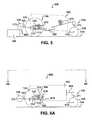
- FIG. 5illustrates the wheelchair 400 traversing over an obstacle 300 .
- the drive wheels 132bring the front anti-tip wheels 120 into engagement with the obstacle 300 .
- the drive wheels 132force the anti-tip wheels 120 up and onto the obstacle.
- the rear anti-tip wheelsare biased against the ground by the biasing member 473 and the drive wheels 132 are biased against the ground by the biasing member 472 .
- Upward movement (indicated by arrow 502 ) of the front anti-tip wheels 120causes the frame 102 to cant.
- the canting of the frame 102may cause some relaxation of the biasing member 472 and/or some compression of the biasing member 473 .
- the drive wheels 132continue to drive the wheelchair 400 forward, and the drive wheels climb over the obstacle 300 .
- the drive wheels 132move the wheelchair 400 further forward to pull the rear anti-tip wheels over the obstacle 300 .
- FIGS. 6A and 6Billustrate another embodiment of a wheelchair 600 .
- the wheelchair 600has a pivot arm 134 and one or more rear anti-tip wheels 108 are connected to the frame 102 by a fixed arm 602 .
- the drive assembly 104is connected to the pivot arm 134 .
- the pivot arm 134is pivotally connected to the frame 102 at a pivot axis 610 .
- the pivot axis 610may be positioned at any location with respect to the frame 102 , including locations near or below the frame.
- the pivot axis 610may be forward or rearward of the axis of rotation 112 of the drive wheel.
- the biasing member 172biases the pivot arm 134 downward relative to the frame as indicated by arrow 618 .
- FIG. 7illustrates the wheelchair 600 traversing over an obstacle 300 .
- the drive wheels 132bring the front anti-tip wheels 120 into engagement with the obstacle 300 .
- the drive wheels 132force the anti-tip wheels 120 up and onto the obstacle.
- the drive wheels 132are biased against the ground by the biasing member 172 .
- Upward movement (indicated by arrow 702 ) of the front anti-tip wheels 120causes the frame 102 to pivot about the pivot axis 610 (indicated by arrow 704 ).
- the pivoting of the frame 102may cause some relaxation of the biasing member 172 depending on the arrangement of the biasing member.
- the drive wheels 132continue to drive the wheelchair 600 forward, and the drive wheels climb over the obstacle 300 .
- the drive wheels 132move the wheelchair 600 further forward to pull the rear anti-tip wheels 108 over the obstacle 300 .
- FIGS. 8A and 8Billustrate another embodiment of a wheelchair 800 .
- the wheelchairincludes track suspension assemblies 806 , 807 (see FIG. 8B ).
- the suspension assemblies 806 , 807are mirror images of one another. As such, only suspension assembly 806 is described in detail.
- the suspension assembly 806may be any arrangement that defines a path of travel of the drive assembly 104 with respect to the frame 102 .
- the suspension assembly 806may include at least one track 808 , at least one follower 810 , and at least one biasing member 172 , such as a spring or other similar device.
- the illustrated suspension assembly 806includes two tracks 808 and two followers 810 , but any number of tracks and followers can be used.
- the illustrated followers 810are attached to the drive assembly 104 and the tracks 808 are attached to the frame 102 .
- the followers 810could be attached to the frame 102 with the tracks 808 attached to the drive assembly 104 .
- the drive assembly 104 and/or frame 102may be otherwise coupled to the tracks 808 and followers 810 .
- the followers 810are slideably disposed in the tracks 808 such that the tracks 808 define the path of relative movement of the drive assembly 104 relative to the frame 102 .
- the illustrated tracks 808are linear and define a path of travel that extends in a generally vertical direction.
- the trackscan be configured to define a path of travel having any shape, extending in any direction, including arcuate shapes.
- the path of travelcan have one or more straight and/or curved portions.
- an arrangementmay be included to rotate the drive assembly 104 relative to the frame 102 as the drive assembly 104 moves along the path of travel.
- the biasing member 172can take a wide variety of different forms, as described above. In the example illustrated by FIGS. 8A and 8B , the biasing member 172 is disposed in the track 808 between an end 812 of the track and the follower 810 . This arrangement biases the drive assembly 104 downward relative to the frame 102 . However, the biasing member 172 can be arranged in any manner to provide a biasing force between the drive assembly 104 and the frame 102 . The biasing member 172 may be connected directly to the frame 102 and the drive assembly 104 or through one or more intermediate members. An optional stop 894 , such as the end surface of the track, may be fixed to the frame to limit downward movement of the drive assembly 104 with respect to the frame. In an exemplary embodiment, the biasing member 172 causes the drive wheel 132 to engage the horizontal support surface 119 when the wheelchair is at rest on the horizontal support surface.
- the wheelchair 800has a rearward link 882 that supports the rear anti-tip wheel 108 .
- the rearward link 882is optionally pivotally connected to the frame at a pivot axis 810 .
- the pivot axis 810may be positioned at any location with respect to the frame 102 , including locations near or below the frame.
- the separate link 882allow for independent movement of the drive assembly 104 relative to the rear anti-tip wheel 108 .
- a separate biasing member 873biases the link 882 downward relative to the frame 102 as indicated by arrow 820 .
- FIG. 9illustrates the wheelchair 800 traversing over an obstacle 300 .
- the drive wheels 132bring the front anti-tip wheels 120 into engagement with the obstacle 300 .
- the drive wheels 132force the anti-tip wheels 120 up and onto the obstacle.
- the rear anti-tip wheels 108are biased against the ground by the biasing member 873 and the drive wheels 132 are biased against the ground by the biasing member 172 .
- Upward movement (indicated by arrow 802 ) of the front anti-tip wheels 120causes the frame 102 to cant.
- the canting of the frame 102may cause some relaxation of the biasing member 172 and some compression of the biasing member 873 .
- the drive wheels 132continue to drive the wheelchair 800 forward, and the drive wheels climb over the obstacle 300 .
- the drive wheels 132move the wheelchair 800 further forward to pull the rear anti-tip wheels over the obstacle 300 .
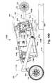
- FIGS. 10A and 10Billustrate another embodiment of a wheelchair 1000 .
- the wheelchair 1000is similar to the wheelchair 800 , with the exception that the movement of the rear anti-tip wheels 108 relative to the frame 102 is at least partially linked to movement of the drive assembly 104 relative to the frame.
- This couplingcan be accomplished in a wide variety of different ways.
- the relative movement of the drive assembly 104 relative to the rear anti-tip wheels 108is restricted by another track and follower arrangement 1002 .
- any arrangementcan be used. Any link or arrangement that transfers at least some portion of motion in at least one direction of the drive assembly 104 to the rear anti-tip wheel 108 can be used.
- the illustrated track and follower arrangement 1002includes at least one track 1008 , at least one follower 1010 , and at least one coupling member 1012 .
- the illustrated follower 1010is attached or coupled to the pivot link 882 and the track 1008 is attached to the frame 102 .
- the follower 1010could be attached to the frame 102 with the track 1008 attached to the pivot link 882 .
- the follower 1010is slideably disposed in the track 1008 .
- the illustrated track 1008is linear and defines a path of travel that extends in a generally vertical direction.
- the trackscan be configured to define a path of travel having any shape, extending in any direction, including arcuate shapes.
- the path of travelcan have one or more straight and/or curved portions.
- the coupling member 1012couples the follower 1010 to the drive assembly 104 .
- the position of the rear anti-tip wheel 108is at least partially dependent on the position of the drive assembly 104 .
- the coupling member 1012can take a wide variety of different forms. Any arrangement of transferring at least some portion of movement of the drive assembly 104 to the follower can be used.
- the follower 1012is an extension of the link 882 that is engaged by the drive assembly 104 when the drive assembly moves upward relative to the frame 102 . This upward movement of the follower 1010 relative to the frame translates into downward movement of the rear anti-tip wheel relative to the frame 102 in the embodiment illustrated by FIG. 10A .
- the wheelchair 1000will traverse obstacles in generally the same manner as the wheelchair 800 , except the movement of the rear anti-tip wheel 108 relative to the frame is somewhat dependent on the position of the drive assembly 104 relative to the frame.
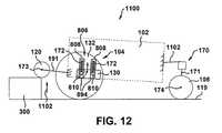
- FIGS. 11A and 11Billustrate another embodiment of a wheelchair 1100 .
- the wheelchair 1100is similar to the wheelchair 1000 , except the rear anti-tip wheel 108 is connected to the frame 102 by a fixed arm 1102 .
- FIG. 12illustrates the wheelchair 1100 traversing over an obstacle 300 .
- the drive wheels 132bring the front anti-tip wheels 120 into engagement with the obstacle 300 .
- the drive wheels 132force the anti-tip wheels 120 up and onto the obstacle.
- the drive wheels 132are biased against the ground by the biasing member 172 .
- Upward movement (indicated by arrow 1102 ) of the front anti-tip wheels 120causes the frame 102 to cant.
- the canting of the frame 102may cause some relaxation of the biasing member 172 depending on the arrangement of the biasing member.
- the drive wheels 132continue to drive the wheelchair 1100 forward, and the drive wheels climb over the obstacle 300 .
- the drive wheels 132move the wheelchair 1100 further forward to pull the rear anti-tip wheels
- FIGS. 13A and 13Billustrate another embodiment of a wheelchair 1300 .
- the wheelchair 1300is similar to the wheelchair 800 , except the rear anti-tip wheels 108 are each coupled to the frame 102 by a track suspension assembly 1306 .
- the suspension assembly 1306may be any arrangement that defines a path of travel of the rear anti-tip wheel with respect to the frame.
- the suspension assembly 1306may include at least one track 1308 , at least one follower 1310 , and at least one biasing member 173 , such as a spring.
- the illustrated suspension assembly 1306includes two tracks 1308 and two followers 1310 , but any number of tracks and followers can be used.
- the illustrated followers 1310are attached to an arm 1350 that carries the rear anti-tip wheel 108 and the tracks 1308 are attached to the frame 102 .
- the followers 1310could be attached to the frame 102 with the tracks 1308 attached to the rear anti-tip wheel.
- the rear anti-tip wheels 108 and/or the frame 102may be otherwise coupled to the tracks 1308 and followers 1310 .
- the followers 1310are slideably disposed in the tracks 1308 such that the tracks 808 define the path of relative movement of the rear anti-tip wheels 108 with respect to the frame 102 .
- the illustrated tracks 808are linear and define a path of travel that extends in a generally vertical direction.
- the trackscan be configured to define a path of travel having any shape, extending in any direction.
- the path of travelcan have one or more straight and/or curved portions.
- the arm 1350can be pivoted or rotated relative to the frame as the arm 1350 and connected anti-tip wheel 108 moves along the path of travel.
- the biasing member 173can take a wide variety of different forms as described above. In the example illustrated by FIGS. 13A and 13B , the biasing member 173 is disposed in the track 1308 between an end 1312 of the track and the follower 1310 . This arrangement biases the anti-tip wheel 108 downward relative to the frame 102 . However, the biasing member 173 can be arranged in any manner to provide a biasing force between the rear anti-tip wheel 108 and the frame 102 . The biasing member 173 may be connected directly to the frame 102 and the anti-tip wheel 108 or through one or more intermediate members.
- a stop 1394such as the end surface of the track, may be fixed to the frame to limit downward movement of the rear anti-tip wheel 108 with respect to the frame.
- the biasing member 173causes the rear anti-tip wheel 108 to engage the horizontal support surface 119 when the wheelchair is at rest on the horizontal support surface.
- an optional motion transfer link 1352may be coupled to the drive assembly 104 and the rear anti-tip wheel 108 to control relative motion therebetween.
- the motion transfer link 1352can take a wide variety of different forms.
- the linkmay be rigid, flexible, or extendible in length. Any link 1352 or arrangement that transfers at least some portion of motion in at least one direction of the drive assembly 104 to the rear anti-tip wheel 108 can be used.
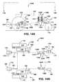
- FIGS. 14A and 14Billustrate another embodiment of a wheelchair 1400 .
- the wheelchair 1400is similar to the wheelchair 1300 , except the track suspension assemblies 806 are replaced with the pivot arm 180 and biasing member 172 arrangement shown in FIGS. 4A and 4B .
- An optional motion transfer link 1452(not shown in FIG. 14B ) may be coupled to the drive assembly 104 and the rear anti-tip wheel 108 to control relative motion therebetween.
- the motion transfer link 1452can take a wide variety of different forms and can be coupled to the suspension assemblies in a wide variety of different ways, including, but not limited to, pivot connections, etc.
- the linkmay be rigid, flexible, or extendible in length. Any link 1452 or arrangement that transfers at least some portion of motion in at least one direction of the drive assembly 104 to the rear anti-tip wheel 108 can be used.
- FIG. 15is a schematic view illustrating drive wheels 132 suspended to sides 1500 of the frame 102 .
- one or more wheels that are suspended from the framesuch as drive wheels 132 , front anti-tip wheels 120 , 121 (not shown in FIG. 15 ) and/or rear anti-tip wheels 108 (not shown in FIG. 15 ), are suspended such that upward and downward movement of the wheel does not result in significant fore and aft movement of the suspended wheel.
- Thiscan be accomplished in a variety of different ways.
- the track and follower arrangements disclosed abovemay be configured to have this effect.
- drive wheels 132are coupled to the frame 102 by a pivot arm 1502 .
- a pivot axis 1504 of the pivot arm 1502is perpendicular or substantially perpendicular to an axis of rotation 112 of the drive wheel (which is generally perpendicular to the sides 1500 of the frame).
- the drive wheel 132does not move substantially fore or aft with respect to the frame 102 .
- Any of the suspensions of wheels relative to the frame disclosed in this applicationcan be replaced with this type of suspension.
- FIGS. 16 and 17illustrate another embodiment of a wheelchair 1700 .
- the wheelchair 1700includes a frame 102 , a seat 103 supported by the frame, first and second drive assemblies 104 , 105 , first and second suspension assemblies 1706 , 1707 , first and second front anti-tip wheels 120 , 121 , and a pair of rear anti-tip wheels 108 .
- Each drive assembly 104 , 105is coupled to the frame 102 .
- the drive assembliesare fixed to the frame 102 .
- the drive assemblies 104 , 105can alternatively be coupled to the frame in a manner that allows relative movement between the drive assemblies and the frame 102 .
- the drive assemblies 104 , 105can be coupled to the frame 102 using any of the suspension assemblies disclosed in this application.
- suspension assemblies 1706 , 1707are mirror images of one another. As such, only suspension assembly 1706 is described in detail.
- a front anti-tip wheel 120is positioned forward of the drive wheels 122 and the rear anti-tip wheel 108 is positioned rearward of the drive wheels.
- the suspension 1706includes a linkage 1709 and a biasing member 172 .
- the linkage 1709couples the front anti-tip wheel 120 to the rear anti-tip wheel 108 such that movement of the front anti-tip wheel relative to the frame 102 is transferred to the rear anti-tip wheel 108 and/or vice versa.
- the linkage 1709may take a wide variety of different forms.
- the linkage 1709couples the front anti-tip wheel 120 to the rear anti-tip wheel 108 such that upward movement of the front anti-tip wheel 120 relative to the frame 102 causes upward movement of the rear anti-tip wheel 108 relative to the frame and/or vice versa.
- a wide variety of different linkages or arrangementsmay couple the front anti-tip wheel 120 and the rear anti-tip wheel 108 such that upward movement of the front anti-tip wheel 120 relative to the frame 102 causes upward movement of the rear anti-tip wheel 108 relative to the frame and/or vice versa.
- the illustrated linkage 1709is but one example of the many different arrangements that may be used.
- the linkage 1709includes a front anti-tip pivot arm 1790 , a rear anti-tip pivot arm 1734 , and a connecting link 1711 .
- the front anti-tip pivot arm 1790is pivotally connected to the frame 102 at a pivot axis 1713 .
- a forward portion 1735 of the front anti-tip pivot arm 1790extends forward from the pivot axis 1713 and a rearward portion 1737 of the front anti-tip pivot arm 1790 extends rearward from the pivot axis 1713 .
- the rear anti-tip pivot arm 1734is pivotally coupled to the frame 102 at a pivot axis 1710 .
- a forward portion 1780 of the rear anti-tip pivot arm 1734extends forward from the pivot axis 1710 and a rearward portion 1782 of the rear anti-tip pivot arm 1734 extends rearward from the pivot axis.
- the pivot axis 1713 and the pivot axis 1710can be positioned at a wide variety of different locations.
- the pivot axis 1713 and the pivot axis 1710can be positioned at any position on the frame and/or positions below the frame by one or more brackets.
- the pivot axis 1713is forward and below the axis of rotation 112 of the drive wheel 132 .
- the pivot axis 1713is aligned with the axis of rotation 112 of the drive wheel.
- the pivot axisis positioned below the axis of rotation 173 of the front anti-tip wheel.
- the pivot axis 1710is positioned forward of a midplane 1750 (i.e. a plane located at a position half way between the front and the back of the frame).
- the illustrated pivot axis 1710is located at or near a bottom of the frame. Nevertheless, pivot axis 1710 can also be positioned very near or even at or behind the mid-plane 1750 .
- the pivot arms 1734 , 1790may be substantially rigid members or may be flexible to provide inherent shock absorbing properties in the pivot arm.
- the pivot arms 1734 , 1790may be made from a wide variety of materials, including, but not limited to, metals and plastics.
- the connecting link 1711couples the front anti-tip pivot arm 1790 to the rear anti-tip pivot arm 1734 .
- the connecting linkmay take a variety of different forms and may be coupled to the pivot arms 1734 , 1790 in a wide variety of different ways.
- the connecting link 1711may have any configuration that transfers motion between the front anti-tip pivot arm 1790 and the rear anti-tip pivot arm 1734 .
- the connecting link 1711is a rigid member that is pivotally connected to the front anti-tip pivot arm 1790 at a pivot axis 1792 and that is pivotally connected to the rear anti-tip pivot arm at a pivot axis 1794 .
- the connecting linkcould also be flexible, or extendible in length and can be coupled to the pivot arms in any manner.
- the biasing member 172can take a wide variety of different forms. Any spring device, devices, or assembly can be used as the biasing member.
- the biasing membermay be a single spring, a bi-directional spring, or multiple spring elements.
- the biasing membermay include a shock absorbing component, for example, the biasing member may be a shock absorber with a spring return 2006 (See FIG. 20C ).
- the biasing member 172is disposed between a mount 1790 that is fixed to the frame and the pivot arm 1734 .
- the biasing member 172 illustrated by FIG. 16is a compression spring that biases the rear anti-tip arm 1734 downward as indicated by arrow 1762 .
- a stop 194may be fixed to the frame to limit downward movement of the pivot arm 1734 with respect to the frame.
- the downward biasing of the rear pivot arm 1734causes downward biasing of the forward anti-tip arm 1790 through the connecting link 1711 as indicated by arrow 1764 .
- FIGS. 16A-16Cillustrate that the biasing member 172 can be an extension spring or a compression spring positioned at a variety of different locations to provide the downward front and rear pivot arms 1790 , 1734 biasing.
- the biasing member 172is an extension spring positioned below the rear anti-tip arm 1734 .
- the biasing member 172is an extension spring positioned above the front anti-tip arm 1790 .
- the biasing member 172is a compression spring positioned above the front anti-tip arm 1790 .
- the biasing member 172is configured to bias the front and rear anti-tip arms 1790 , 1734 upward. This can be accomplished in a variety of different ways.
- the biasing member 172can be changed from a compression spring to an extension spring and in the examples illustrated by FIGS. 16A and 16B , the biasing member 172 can be changed from an extension spring to a compression spring.
- the biasing member 172is configured to bias the pivot arm 134 to a home position, such as the position relative to the frame illustrated by FIG. 16 .
- Biasing to a home positioncan be accomplished in a variety of different ways.
- a bidirectional springcan be coupled to the linkage 1709 and/or any one or more of the spring arrangements that bias the pivot arms downward can be used with any one or more of the spring arrangements that bias the pivot arms upward.
- the biasing member 172biases the arms upward, downward, or to a home position
- the biasing membercauses the rear anti-tip wheel 108 to engage the horizontal support surface 119 and the front anti-tip wheel to be spaced apart from the horizontal support surface when the wheelchair is at rest on the horizontal support surface.
- the front anti-tip wheel 120engages the horizontal support surface 119 when the wheelchair is at rest on the horizontal support surface.
- the front anti-tip wheel 120is connected to the forward end 1735 of the front anti-tip arm 1790 and the rear anti-tip wheel is connected to the rearward end 1782 of the rear anti-tip arm 1734 .
- the first and second front anti-tip wheels 120 , 121 and the rear anti-tip wheels 108may take a wide variety of different forms.
- the front anti-tip wheels 120 , 121are mounted for rotation only about a substantially horizontal axis 173 and the rear anti-tip wheels 108 are wheels of caster assemblies 170 .
- FIGS. 19A-19Fillustrate a more specific embodiment of the wheelchair 1700 illustrated by FIGS. 16 and 17 . It should be understood that the present application is not limited to the more specific embodiment illustrated by FIGS. 19A-19D .
- FIG. 19Aillustrates the wheelchair 1700 at rest in the normal operating position on the horizontal support surface 119 .
- FIG. 19Billustrates the wheelchair of FIG. 19A with the drive wheel 132 shown schematically to more clearly illustrate the suspension 1706 .
- FIGS. 18 and 19 C- 19 Eillustrate operation of the wheelchair 1700 to traverse over an obstacle 300 .
- the drive wheels 132bring the front anti-tip wheels 120 into engagement with the obstacle 300 .
- the drive wheels 132force the anti-tip wheels 120 , 121 up and onto the obstacle. This cause the anti-tip wheels 120 to move upward with respect to the frame 102 , which, in turn, causes the anti-tip wheels 108 to move upward relative to the frame 102 .
- the linkage 1709transfers the upward movement of the front anti-tip wheel 120 to the rear anti-tip wheel 108 against the biasing force of the biasing member 172 .
- the front anti-tip pivot arm 1790rotates about the pivot axis 1713 as indicated by arrow 1910 .
- the pivot axis 1713is coincident with the axis of rotation 112 of the drive wheel 132 , but could be positioned at any location.
- the rotation of the front anti-tip pivot arm 1790forces the connecting link 1711 downward as indicated by arrow 1912 .
- the downward movement of the connecting link 1711causes the rear anti-tip pivot arm 1734 to rotate about the pivot axis 1710 as indicated by arrow 1914 .
- the rearward portion 1782 of the rear anti-tip pivot arm 1734moves relatively upward with respect to the frame against the biasing force of the biasing member 172 as indicated by arrow 1916 .
- the drive wheels 132 and the rear anti-tip wheels 108remain on the ground and the upward movement (indicated by arrow 302 ) of the front anti-tip wheels 120 may cause the frame 102 to cant.
- the drive wheels 132continue to drive the wheelchair 1700 forward.
- the drive wheels 132engage and climb over the obstacle 300 .
- the drive wheels 132move the wheelchair 1700 further forward on the obstacle 300 .
- the rear anti-tip wheels 108engage the obstacle 300 .
- the biasing member 172cushions the impact between the rear anti-tip wheels 108 and the obstacle.
- the drive wheels 132continue to drive the wheelchair 1700 forward and pull the rear anti-tip wheels 108 up onto the obstacle 300 .
- a variety of situationscan cause forward tipping of a wheelchair. For example, traveling down a hill, decelerating rapidly, and driving off of an obstacle, such as a curb can cause forward tipping.
- the front anti-tip wheels 120engage the support surface to prevent excessive forward tipping.
- the biasing member 172is compressed by the linkage 1709 to cushion the impact with the support surface.
- the amount of force applied by the biasing member 172 , and/or the position of the pivot axis 1713can be adjusted or selected to control the amount of resistance to forward tip provided by the front anti-tip pivot arm 1790 .
- the resistance to forward tipcan be increased for a heavy user by increasing a spring constant of the biasing member and/or shortening the distance between the pivot axis 1713 and the front anti-tip wheel 120 .
- the spring constant of the biasing membercan be decreased and/or the distance between the pivot axis 1713 and the front anti-tip wheel 120 can be increased to provide smoother curb climbing for a lighter user that may need less resistance to forward tip.
- FIGS. 23 and 24illustrate another embodiment of a wheelchair 2300 .
- the wheelchair 2300includes a frame 102 , first and second drive assemblies 104 , 105 , first and second suspension assemblies 2306 , 2307 , first and second front anti-tip wheels 120 , 121 , and one or more rear anti-tip wheels 108 .
- Each drive assembly 104 , 105is coupled to the frame 102 .
- the drive assembliesare fixed to the frame 102 .
- the drive assemblies 104 , 105can alternatively be coupled to the frame in a manner that allows relative movement between the drive assemblies and the frame 102 .
- the drive assemblies 104 , 105can be coupled to the frame 102 using any of the suspension assemblies disclosed in this application or any other suspension arrangement.
- suspension assemblies 2306 , 2307are mirror images of one another. As such, only suspension assembly 2306 is described in detail.
- a front anti-tip wheel 120is positioned forward of the drive wheels 122 and the rear anti-tip wheel 108 is positioned rearward of the drive wheels.
- the suspension 2306includes a linkage 2309 and a biasing member 172 .
- the linkage 2309couples the front anti-tip wheel 120 to the rear anti-tip wheel 108 such that movement of the front anti-tip wheel relative to the frame 102 is transferred to the rear anti-tip wheel 108 and/or vice versa.
- the linkage 2309may take a wide variety of different forms.
- the linkage 2309couples the front anti-tip wheel 120 to the rear anti-tip wheel 108 such that upward movement of the front anti-tip wheel 120 relative to the frame 102 causes upward movement of the rear anti-tip wheel 108 relative to the frame and vice versa.
- a wide variety of different linkages or arrangementsmay couple the front anti-tip wheel 120 and the rear anti-tip wheel 108 such that upward movement of the front anti-tip wheel 120 relative to the frame 102 causes upward movement of the rear anti-tip wheel 108 relative to the frame and/or vice versa.
- the illustrated linkage 2309is but one example of the many different arrangements that may be used.
- the linkage 2309includes a front anti-tip pivot arm 2390 , a rear anti-tip pivot arm 2334 , and a connecting link 2311 .
- the front anti-tip pivot arm 2390is pivotally connected to the frame 102 at a pivot axis 2313 .
- a first portion 2335 of the front anti-tip pivot arm 2390extends forward from the pivot axis 2313 and a second portion 2337 of the front anti-tip pivot arm 2390 extends upward from the first portion 2335 .
- the rear anti-tip pivot arm 2334is pivotally coupled to the frame 102 at a pivot axis 2310 .
- a forward portion 2380 of the rear anti-tip pivot arm 2334extends forward from the pivot axis 2310 and a rearward portion 2382 of the rear anti-tip pivot arm 2334 extends rearward from the pivot axis.
- the pivot axis 2313 and the pivot axis 2310can be positioned at a wide variety of different locations.
- the pivot axis 2313 and the pivot axis 2310can be positioned at any position on the frame and/or positions below the frame by one or more brackets.
- the pivot axis 2313is forward and below the axis of rotation 112 of the drive wheel 132 .
- FIG. 23the pivot axis 2313 is forward and below the axis of rotation 112 of the drive wheel 132 .
- the pivot axis 2310is positioned forward of a midplane 2350 (i.e. a plane located at a position half way between the front and the back of the frame).
- the illustrated pivot axis 2310is located at or near a bottom of the frame. Nevertheless, pivot axis 2310 can also be positioned very near or even at or behind the mid-plane 2350 .
- the pivot arms 2334 , 2390may be substantially rigid members or may be flexible to provide inherent shock absorbing properties in the pivot arm.
- the pivot arms 2334 , 2390may be made from a wide variety of materials, including, but not limited to, metals and plastics.
- the connecting link 2311couples the front anti-tip pivot arm 2390 to the rear anti-tip pivot arm 2334 .
- the connecting linkmay take a variety of different forms and may be coupled to the pivot arms 2334 , 2390 in a wide variety of different ways.
- the connecting link 2311may have any configuration that transfers motion between the front anti-tip pivot arm 2390 and the rear anti-tip pivot arm 2334 .
- the connecting link 2311is a rigid member that is pivotally connected to the front anti-tip pivot arm 2390 at a pivot axis 2392 and that is pivotally connected to the rear anti-tip pivot arm at a pivot axis 2394 .
- the connecting linkcould also be flexible, or extendible in length and can be coupled to the pivot arms in any manner.
- the biasing member 172can take a wide variety of different forms. Any spring device, devices, or assembly can be used as the biasing member.
- the biasing membermay be a single spring, a bi-directional spring, or multiple spring elements.
- the biasing membermay include a shock absorbing component, for example, the biasing member may be a shock absorber with a spring return 2006 (See FIG. 20C ).
- the biasing member 172is connected (optionally pivotally connected) between a first mount 2391 that is connected to the frame 102 and a second mount 2393 that is connected to the front pivot arm 2390 .
- a stop 194may be fixed to the frame to limit downward movement of the pivot arm 2334 and/or the pivot arm 2390 with respect to the frame.
- the downward biasing of the front pivot arm 2390causes downward biasing of the rear anti-tip arm 2334 through the connecting link 2311 as indicated by arrow 2362 .
- FIG. 23Ais similar to the embodiment illustrated by FIG. 23 , except, the biasing member 172 is connected (optionally pivotally connected) between a first mount 2391 A that is connected to the frame 102 and a second mount 2393 A that is connected to the rear pivot arm 2334 (instead of the front pivot arm 2390 ).
- the downward biasing of the rear pivot arm 2334causes downward biasing of the front anti-tip arm 2390 through the connecting link 2311 as indicated by arrow 2364 .
- the biasing member 172can be an extension spring, a compression spring, or any type of extendible or retractable device or member positioned at a variety of different locations to provide the downward front and rear pivot arms 2390 , 2334 biasing.
- the biasing member 172is configured to bias the front and rear anti-tip arms 2390 , 2334 upward. This can be accomplished in a variety of different ways. For example, the biasing member 172 can be changed to apply force in the direction opposite the direction indicated by arrow 2364 .
- the front and rear anti-tip wheels 120 , 108are biased into contact with the support surface.
- the front and rear anti-tip wheels 120 , 108can be biased to any home position.
- the front anti-tip wheel 120 or the rear anti-tip wheel 108can be biased to a home position that is above the support surface. Biasing to a home position can be accomplished in a variety of different ways.
- a bidirectional springcan be coupled to the linkage 2309 and/or any one or more spring arrangements that bias the pivot arms downward can be used with any one or more spring arrangements that bias the pivot arms upward.
- the biasing member 172biases the arms upward, downward, or to a home position, the biasing member causes the front anti-tip wheel 120 and the rear anti-tip wheel 108 to engage the horizontal support surface 119 when the wheelchair is at rest on the horizontal support surface.
- the front anti-tip wheel 120is spaced apart from the horizontal support surface 119 when the wheelchair is at rest on the horizontal support surface.
- the front anti-tip wheel 120is a wheel of a caster assembly.
- the illustrated front anti-tip wheelis rotatable about a caster axis 175 .
- the illustrated front anti-tip wheelis connected to the forward end 2335 of the front anti-tip arm 2390 and the rear anti-tip wheel is connected to the rearward end 2382 of the rear anti-tip arm 2334 .
- the first and second front anti-tip wheels 120 , 121 and the rear anti-tip wheels 108may take a wide variety of different forms.
- the front anti-tip wheels 120 , 121 and the rear anti-tip wheels 108are wheels of caster assemblies.
- FIGS. 26A and 26Billustrate a more specific embodiment of the wheelchair 2300 illustrated by FIGS. 23 and 24 . It should be understood that the present application is not limited to the more specific embodiment illustrated by FIGS. 26A and 26B .
- FIG. 26Aillustrates the wheelchair 2300 at rest in the normal operating position on the horizontal support surface 119 .
- FIG. 26Billustrates the wheelchair of FIG. 26A with the drive wheel 132 removed to more clearly illustrate the suspension 2306 .
- FIGS. 25 and 25Aillustrate operation of the exemplary embodiments of the wheelchair 2300 to traverse over an obstacle 300 .
- the drive wheels 132bring the front anti-tip wheels 120 into engagement with the obstacle 300 .
- the drive wheels 132force the anti-tip wheels 120 , 121 up and onto the obstacle. This cause the anti-tip wheels 120 to move upward with respect to the frame 102 , which, in turn, causes the anti-tip wheels 108 to move upward relative to the frame 102 .
- the linkage 2309transfers the upward movement of the front anti-tip wheel 120 to the rear anti-tip wheel 108 against the biasing force of the biasing member 172 .
- the biasing member 172is compressed as indicated by arrows 2500 in FIG. 25 and arrows 2500 A in FIG. 25A .
- the front anti-tip pivot arm 2390rotates about the pivot axis 2313 as indicated by arrow 2410 .
- the rotation of the front anti-tip pivot arm 2390forces the connecting link 2311 downward as indicated by arrow 2412 .
- the downward movement of the connecting link 2311causes the rear anti-tip pivot arm 2334 to rotate about the pivot axis 2310 as indicated by arrow 2414 .
- the rearward portion 2382 of the rear anti-tip pivot arm 2334moves relatively upward with respect to the frame against the biasing force of the biasing member 172 as indicated by arrow 2416 .
- the drive wheels 132 and the rear anti-tip wheels 108remain on the ground and the upward movement (indicated by arrow 302 ) of the front anti-tip wheels 120 may cause the frame 102 to cant.
- the drive wheels 132continue to drive the wheelchair 2300 forward.
- the drive wheels 132engage and climb over the obstacle 300 .
- the drive wheels 132move the wheelchair 2300 further forward on the obstacle 300 .
- the rear anti-tip wheels 108engage the obstacle 300 .
- the biasing member 172through the linkage 2309 in the FIG. 23 embodiment (or directly in the FIG. 23A embodiment), cushions the impact between the rear anti-tip wheels 108 and the obstacle.
- the drive wheels 132continue to drive the wheelchair 2300 forward and pull the rear anti-tip wheels 108 up onto the obstacle 300 .
- the front anti-tip wheels 120are configured to engage the support surface to prevent excessive forward tipping.
- the biasing member 172is compressed by the linkage 2309 to cushion the impact with the support surface.
- the amount of force applied by the biasing member 172 , and/or the position of the pivot axis 2313can be adjusted or selected to control the amount of resistance to forward tip provided by the front anti-tip pivot arm 2390 .
- the resistance to forward tipcan be increased for a heavy user by increasing a spring constant of the biasing member and/or shortening the distance between the pivot axis 2313 and the front anti-tip wheel 120 .
- the spring constant of the biasing membercan be decreased and/or the distance between the pivot axis 2313 and the front anti-tip wheel 120 can be increased to provide smoother curb climbing for a lighter user that may need less resistance to forward tip.
- the motion of one or more wheels with respect to the framemay be linked to the motion of one or more other wheels with respect to the frame.
- the wheelsmay be linked in a wide variety of different ways.
- one or more rigid linksmay couple the relative motion of one or more wheels relative to the frame to one or more other wheels with respect to the frame or a variable length link may couple the relative motion of one or more wheels to one or more other wheels.
- FIGS. 20A , 20 B, and 20 Cillustrate examples of variable length links.
- FIG. 20Aillustrates a shock absorber 2002
- FIG. 20Billustrates a spring 2004
- FIG. 20Cillustrates a shock absorber with a spring return 2006 .
- the variable length linksare pivotally connected to pivot arms, but the variable length links could be coupled to the wheels in any manner.
- a wide variety of other variable length linksmay also be used.
- one or more of the anti-tip wheels 120 , 121 , 108 of the wheelchairare replaced with an anti-tip structure that is not a wheel.
- an anti-tip structure that is not a wheelmay be used in any wheelchair configuration.
- Anti-tip wheelsmay be replaced with a wide variety of different anti-tip structures. For example, any structure capable of engaging an obstacle (for example, a curb), and sliding or otherwise moving over the obstacle can be used.
- FIGS. 21A and 21Billustrate embodiments where the anti-tip structure is a ski 2100 .
- the illustrated ski 2100has arched contact surfaces 2102 , but can have any shape and may be flat.
- FIGS. 22A and 22Billustrate embodiments where the anti-tip structures are continuous tracks 2200 .
- the tracks 2200include belts 2202 disposed around rollers 2204 , such that the belts are moveable around the rollers.
- the anti-tip structuresmay be mounted to the wheelchair in any orientation with respect to the wheelchair.
- bottom or contact surfaces 2102 , 2202 of the anti-tip structuresare inclined upward, away from a support arm 2104 that connects or couples the anti-tip structure to the frame. This upward inclination facilitates movement of the anti-tip structure over the obstacle.
- the anti-tip structures 2100 , 2200can be mounted or coupled to the support arm 2104 in a variety of different ways. In the embodiments illustrated by FIGS. 21A and 22A , the anti-tip structures 2100 , 2200 are fixed to the support arm 2104 . In the embodiments illustrated by FIGS. 21B and 22B , the anti-tip structures 2100 , 2200 are moveably coupled to the support arm 2104 . The anti-tip structures 2100 , 2200 can be moveably coupled to the support arm 2104 in a variety of different ways. Any arrangement that allows the anti-tip structure 2100 , 2200 to move with respect to the support arm 2104 can be used.
- the anti-tip structures 2100 , 2200are pivotally connected to the support arm 2104 .
- An optional biasing member 2150such as a spring, biases the anti-tip structure 2100 , 2200 forward as indicated by arrow 2152 .
- the biasing member 2150cushions impact between the anti-tip structure 2100 , 2200 .
- pivotal connectionscan be made of any number of structures including bearing assemblies, pins, nuts and bolts, and frictionless sleeve assemblies.
- springs or shock absorberscan be added between pivoting and non-pivoting components to limit, dampen, or somewhat resist the pivotal motions of these components. Therefore, the invention, in its broader aspects, is not limited to the specific details, the representative apparatus, and illustrative examples shown and described. Accordingly, departures can be made from such details without departing from the spirit or scope of the applicant's general inventive concept.
Landscapes
- Health & Medical Sciences (AREA)
- Life Sciences & Earth Sciences (AREA)
- Animal Behavior & Ethology (AREA)
- General Health & Medical Sciences (AREA)
- Public Health (AREA)
- Veterinary Medicine (AREA)
- Handcart (AREA)
- Vehicle Body Suspensions (AREA)
- Automatic Cycles, And Cycles In General (AREA)
- Axle Suspensions And Sidecars For Cycles (AREA)
Abstract
Description
Claims (14)
Priority Applications (5)
| Application Number | Priority Date | Filing Date | Title |
|---|---|---|---|
| US12/900,548US9010470B2 (en) | 2009-10-09 | 2010-10-08 | Wheelchair suspension |
| US14/690,678US9913768B2 (en) | 2009-10-09 | 2015-04-20 | Wheelchair suspension |
| US15/918,730US11096845B2 (en) | 2009-10-09 | 2018-03-12 | Wheelchair suspension |
| US17/394,525US11857470B2 (en) | 2009-10-09 | 2021-08-05 | Wheelchair suspension |
| US18/462,557US20230414421A1 (en) | 2009-10-09 | 2023-09-07 | Wheelchair suspension |
Applications Claiming Priority (2)
| Application Number | Priority Date | Filing Date | Title |
|---|---|---|---|
| US25022209P | 2009-10-09 | 2009-10-09 | |
| US12/900,548US9010470B2 (en) | 2009-10-09 | 2010-10-08 | Wheelchair suspension |
Related Child Applications (1)
| Application Number | Title | Priority Date | Filing Date |
|---|---|---|---|
| US14/690,678DivisionUS9913768B2 (en) | 2009-10-09 | 2015-04-20 | Wheelchair suspension |
Publications (2)
| Publication Number | Publication Date |
|---|---|
| US20110083913A1 US20110083913A1 (en) | 2011-04-14 |
| US9010470B2true US9010470B2 (en) | 2015-04-21 |
Family
ID=43853948
Family Applications (5)
| Application Number | Title | Priority Date | Filing Date |
|---|---|---|---|
| US12/900,548Active2033-06-03US9010470B2 (en) | 2009-10-09 | 2010-10-08 | Wheelchair suspension |
| US14/690,678ActiveUS9913768B2 (en) | 2009-10-09 | 2015-04-20 | Wheelchair suspension |
| US15/918,730Active2032-08-03US11096845B2 (en) | 2009-10-09 | 2018-03-12 | Wheelchair suspension |
| US17/394,525Active2031-05-21US11857470B2 (en) | 2009-10-09 | 2021-08-05 | Wheelchair suspension |
| US18/462,557PendingUS20230414421A1 (en) | 2009-10-09 | 2023-09-07 | Wheelchair suspension |
Family Applications After (4)
| Application Number | Title | Priority Date | Filing Date |
|---|---|---|---|
| US14/690,678ActiveUS9913768B2 (en) | 2009-10-09 | 2015-04-20 | Wheelchair suspension |
| US15/918,730Active2032-08-03US11096845B2 (en) | 2009-10-09 | 2018-03-12 | Wheelchair suspension |
| US17/394,525Active2031-05-21US11857470B2 (en) | 2009-10-09 | 2021-08-05 | Wheelchair suspension |
| US18/462,557PendingUS20230414421A1 (en) | 2009-10-09 | 2023-09-07 | Wheelchair suspension |
Country Status (6)
| Country | Link |
|---|---|
| US (5) | US9010470B2 (en) |
| EP (2) | EP2485698B1 (en) |
| AU (1) | AU2010303354C1 (en) |
| CA (1) | CA2775916C (en) |
| NZ (1) | NZ599108A (en) |
| WO (1) | WO2011044405A1 (en) |
Cited By (17)
| Publication number | Priority date | Publication date | Assignee | Title |
|---|---|---|---|---|
| US20140339005A1 (en)* | 2007-02-08 | 2014-11-20 | Iinvacare Corporation | Wheelchair suspension |
| US20150129328A1 (en)* | 2011-02-07 | 2015-05-14 | Mobility 2000 (Australia) Limited | Step-Climbing Attachment for a Wheeled Chair |
| US20150196441A1 (en)* | 2013-12-16 | 2015-07-16 | Pride Mobility Products Corporation | Elevated Height Wheelchair |
| US20160051425A1 (en)* | 2014-08-20 | 2016-02-25 | Energy Control Limited | Front suspension system for an electric wheelchair |
| US9370455B2 (en) | 2001-10-10 | 2016-06-21 | Invacare Corporation | Wheelchair suspension |
| US9700470B2 (en) | 2012-02-15 | 2017-07-11 | Invacare Corporation | Wheelchair suspension |
| US9827823B2 (en) | 2007-02-14 | 2017-11-28 | Invacare Corporation | Stability control system |
| US9907712B2 (en)* | 2011-09-20 | 2018-03-06 | Dane Technologies, Inc. | Powered wheelchair with articulating drive wheels |
| US9913768B2 (en) | 2009-10-09 | 2018-03-13 | Invacare Corporation | Wheelchair suspension |
| US9925100B2 (en) | 2002-10-25 | 2018-03-27 | Invacare Corporation | Suspension for wheeled vehicles |
| US9987177B2 (en) | 2000-10-27 | 2018-06-05 | Invacare Corporation | Obstacle traversing wheelchair |
| US10772774B2 (en) | 2016-08-10 | 2020-09-15 | Max Mobility, Llc | Self-balancing wheelchair |
| US20210101630A1 (en)* | 2019-10-08 | 2021-04-08 | Macpion Corp., Ltd. | Wheel drive apparatus of automated guided vehicle |
| US11191685B2 (en) | 2016-02-27 | 2021-12-07 | Pride Mobility Products Corporation | Adjustable height wheelchair |
| US11213441B2 (en) | 2002-10-25 | 2022-01-04 | Invacare Corporation | Suspension for wheeled vehicles |
| US11903887B2 (en) | 2020-02-25 | 2024-02-20 | Invacare Corporation | Wheelchair and suspension systems |
| US12409085B2 (en) | 2022-07-07 | 2025-09-09 | Permobil Ab | Powered midwheel drive wheelchair with standing capability |
Families Citing this family (20)
| Publication number | Priority date | Publication date | Assignee | Title |
|---|---|---|---|---|
| US20110253464A1 (en)* | 2010-04-15 | 2011-10-20 | Freerider Corp. | Suspension system for electric wheelchair |
| CN102283749B (en)* | 2011-06-27 | 2013-04-03 | 胡达广 | Electric wheelchair for multiple road conditions |
| EP3137034B1 (en)* | 2014-04-29 | 2018-02-28 | Reac Ab | Powered wheelchair |
| EP3127520B1 (en)* | 2014-09-19 | 2017-12-13 | Permobil AB | Chassis arrangement for an electrically powered wheelchair and an electrically powered wheelchair comprising the same |
| US10052247B2 (en)* | 2015-08-24 | 2018-08-21 | Dream Roller Mobility, LLC | Wheelchair with four wheel independent suspension and modular seating |
| US10912688B2 (en)* | 2015-09-25 | 2021-02-09 | The United States Government As Represented By The Department Of Veterans Affairs | Mobility enhancement wheelchair |
| DE202016003870U1 (en)* | 2016-06-21 | 2017-09-22 | Kuka Roboter Gmbh | Climbing device for a wheel |
| TWI592148B (en)* | 2016-06-22 | 2017-07-21 | Electric wheelchair frame | |
| EP3266433B1 (en)* | 2016-07-07 | 2020-05-06 | Permobil AB | Swing arm linkage for a mid-wheel drive wheelchair |
| EP3354247B1 (en)* | 2017-01-31 | 2020-03-18 | Permobil AB | Swing arm assembly for a mid-wheel drive wheelchair |
| US10864127B1 (en) | 2017-05-09 | 2020-12-15 | Pride Mobility Products Corporation | System and method for correcting steering of a vehicle |
| CN107174420A (en)* | 2017-07-10 | 2017-09-19 | 常州摩本智能科技有限公司 | Electric wheel-chair vehicle |
| CN109435677B (en)* | 2018-12-05 | 2023-09-19 | 深圳市远弗科技有限公司 | An active obstacle-crossing wheel set |
| CN111973353B (en)* | 2019-05-21 | 2022-07-19 | 伍必翔 | An electric wheelchair with its pivoting front cantilever and power frame that is elastically linked with the frame |
| CN113086051A (en)* | 2021-04-30 | 2021-07-09 | 深圳市普渡科技有限公司 | Suspension device, chassis with same and robot |
| US12151922B2 (en)* | 2021-06-22 | 2024-11-26 | Symbotic Llc | Autonomous transport vehicle with synergistic vehicle dynamic response |
| TWI794977B (en)* | 2021-09-15 | 2023-03-01 | 康揚股份有限公司 | The base structure of the electric wheelchair |
| EP4261113A1 (en)* | 2022-04-12 | 2023-10-18 | Yandex Self Driving Group Llc | Robotic vehicle and a support assembly for a wheel thereof |
| DE112022007341T5 (en)* | 2022-06-06 | 2025-03-27 | Jtekt Corporation | Electric vehicle and electric vehicle assistance device |
| CA3168572A1 (en)* | 2022-07-13 | 2024-01-13 | Invacare Corporation | Wheelchair and suspension systems |
Citations (347)
| Publication number | Priority date | Publication date | Assignee | Title |
|---|---|---|---|---|
| US865514A (en) | 1906-12-04 | 1907-09-10 | Paul Muellenmeister | Sick and invalid carriage. |
| US1116086A (en) | 1913-08-25 | 1914-11-03 | Clarence E Lewis | Table-caster. |
| US1151414A (en)* | 1914-07-03 | 1915-08-24 | George P Steinbach | Child's sulky. |
| GB151915A (en) | 1920-06-18 | 1920-10-07 | Frank Townshend | Improvements in pillion seats for motor cycles |
| GB154369A (en) | 1919-09-11 | 1920-12-02 | Charles Herbert Lamb | Improvements in pillion seats for motor cycles, cycles, or the like |
| GB265885A (en) | 1926-10-06 | 1927-02-17 | Wittkop & Co Herforderstrasse | Saddle for bicycles, motor cycles and the like |
| US1773254A (en) | 1928-12-07 | 1930-08-19 | Joseph L Becker | Stabilizer for road-grading machines |
| US1973627A (en) | 1933-03-10 | 1934-09-11 | Evan C Harter | Chair |
| GB474349A (en) | 1937-04-23 | 1937-10-29 | Max Schubert | Improvements in or relating to cycle saddles |
| US2398211A (en) | 1944-06-26 | 1946-04-09 | Indian Motocycle Company | Spring suspension for saddles |
| US2427482A (en) | 1945-12-14 | 1947-09-16 | Weissman David | Attachment for baby carriages and the like |
| US2767995A (en) | 1953-06-08 | 1956-10-23 | Robert H Stout | Tractor anti-tilting attachment |
| GB841175A (en) | 1957-01-10 | 1960-07-13 | Maurice Francois Alexandre Jul | Improvements in suspension systems for automobile vehicles |
| US2949153A (en) | 1955-06-30 | 1960-08-16 | Hickman Ind Inc | Seat structure |
| US2986200A (en) | 1959-04-02 | 1961-05-30 | Nobile Frank | Wheel chair construction |
| US3104112A (en) | 1962-07-02 | 1963-09-17 | Jesse W Crail | Stair climbing wheel chair |
| US3174176A (en) | 1963-01-03 | 1965-03-23 | Lockheed Aircraft Corp | Lock for relatively pivoted structures |
| US3191990A (en) | 1962-05-31 | 1965-06-29 | Rugg Donald Edwin | Reclining mechanism for wheelchairs and the like |
| US3195670A (en) | 1962-08-17 | 1965-07-20 | Ford Motor Co | Torsion bar vehicle suspension |
| US3210092A (en) | 1962-05-29 | 1965-10-05 | Daimler Benz Ag | Pivotal wheel suspension for motor vehicles |
| US3282605A (en) | 1965-01-08 | 1966-11-01 | Russell E Nihlean | Runabout wheelchair |
| US3314672A (en) | 1965-05-10 | 1967-04-18 | Persson Bror Gote | Resilient support for seats, especially for motor vehicles |
| US3506079A (en) | 1968-10-10 | 1970-04-14 | Herman J Madler | Six-wheeled vehicle with independent wheel suspension |
| US3573877A (en) | 1969-05-19 | 1971-04-06 | Burton H Locke | Curb-climbing attachment for wheel chairs |
| US3580591A (en) | 1968-12-24 | 1971-05-25 | Lovelace Foundation For Medica | Wheelchair attachment |
| US3589700A (en) | 1967-05-17 | 1971-06-29 | Regie National Des Usines Renq | Flexibility corrector for vehicle suspension |
| US3592282A (en) | 1969-09-12 | 1971-07-13 | Robert L Soileau | Stair-traversing wheelchair apparatus |
| US3602522A (en) | 1969-02-14 | 1971-08-31 | Rodvinon I Zamotin | Wheel chair |
| US3627157A (en) | 1968-07-01 | 1971-12-14 | Post Office | Lifting devices |
| US3661228A (en) | 1969-12-23 | 1972-05-09 | Jay L Glasser | Wheel chair lift |
| US3664450A (en) | 1969-06-02 | 1972-05-23 | Udden Edward Carl | Electrically powered four-wheeled single vehicle |
| US3682462A (en) | 1970-09-14 | 1972-08-08 | Robert D Papousek | Shock absorbers for vehicles |
| US3689103A (en) | 1970-11-27 | 1972-09-05 | Pneumo Dynamics Corp | Variable height vehicle suspension |
| US3709313A (en) | 1971-01-21 | 1973-01-09 | Walt Disney Prod | Articulated vehicle |
| DE2256934A1 (en) | 1971-11-23 | 1973-05-30 | Smallfry Ltd | VEHICLE SUSPENSION, IN PARTICULAR FOR A MOTOR VEHICLE |
| FR2215054A5 (en) | 1973-01-23 | 1974-08-19 | Folco Zambelli Gian Matteo | |
| US3848883A (en) | 1973-08-08 | 1974-11-19 | S Breacain | Wheelchair anti-tip apparatus |
| US3862751A (en) | 1972-09-28 | 1975-01-28 | Bernard L Schwaller | Dual stage compressor spring |
| US3876012A (en) | 1972-01-18 | 1975-04-08 | Excel Ind | Anti-overturning implement vehicle |
| US3881773A (en) | 1974-06-03 | 1975-05-06 | Everest & Jennings | Reclining back wheelchair |
| US3883153A (en) | 1973-06-25 | 1975-05-13 | Bhupindar Singh | Apparatus for suppressing spring action between the wheel mounts and frame of a vehicle |
| US3893529A (en) | 1974-04-22 | 1975-07-08 | Jr Andrew Karchak | Wheelchair drive package |
| US3901337A (en) | 1971-11-24 | 1975-08-26 | Spastics Soc | Wheel chairs |
| US3901527A (en) | 1973-03-08 | 1975-08-26 | Uzi Danziger | Wheel chair with extensible wheel base to facilitate ingress and egress |
| US3905437A (en) | 1973-07-27 | 1975-09-16 | U M I Kk | Electrically drivable wheelchair |
| US3917312A (en) | 1974-07-29 | 1975-11-04 | Everst & Jennings Inc | Indoor/outdoor wheelchair frame |
| US3930551A (en) | 1973-06-09 | 1976-01-06 | Harold Cragg | Electric drive for wheel chairs |
| US3952822A (en) | 1973-03-19 | 1976-04-27 | Stiftelsen Teknisk Hjalp At Handikappade Permobilstiftelsen | Electrically powered wheel-chair for indoor and outdoor use |
| US3953054A (en)* | 1973-03-19 | 1976-04-27 | Permobilstiftelsen | Hand operated wheel-chair |
| US3976152A (en) | 1973-12-05 | 1976-08-24 | Albert Bell | Wheelchair having pivotable ramp for climbing curbs |
| US4078817A (en) | 1976-06-10 | 1978-03-14 | Reme Enterprises, Inc. | Shock absorber attachment for wheelchairs or the like |
| GB1503910A (en) | 1974-11-07 | 1978-03-15 | Hanger & Co Ltd J E | Wheelchairs |
| US4108449A (en) | 1977-01-31 | 1978-08-22 | Rhodes Thomas J | Stair-climbing wheelchair |
| US4118020A (en) | 1977-08-10 | 1978-10-03 | Caterpillar Tractor Co. | Spring assembly and method of assembly thereof |
| US4119163A (en) | 1977-10-03 | 1978-10-10 | Douglas Ball | Curb climbing wheel chair |
| US4128137A (en) | 1976-02-24 | 1978-12-05 | National Research Development Corporation | Peripatetic vehicles |
| FR2399822A1 (en) | 1977-08-09 | 1979-03-09 | Dupont Lit Sa | Folding wheel chair for handicapped people - consists of frame on two drive wheels, with seat mounted by parallel arms raised and lowered by jack |
| US4190263A (en) | 1978-05-22 | 1980-02-26 | Albuquerque Patents, Ltd. | Wheelchair with shock absorber |
| US4222449A (en) | 1978-06-08 | 1980-09-16 | Feliz Jack M | Step-climbing wheel chair |
| US4245847A (en) | 1979-05-24 | 1981-01-20 | Christopher Knott | Wheelchair |
| US4247125A (en) | 1978-05-08 | 1981-01-27 | Rayment Ena M | Wheelchair |
| US4264085A (en) | 1979-04-20 | 1981-04-28 | Frank Volin | Wheelchair convenience attachments |
| US4310167A (en) | 1980-05-15 | 1982-01-12 | The University Of Virginia Alumni Patents Foundation | Center of gravity wheelchair with articulated chassis |
| WO1982000445A1 (en) | 1980-08-06 | 1982-02-18 | B Schultz | Vehicular suspension |
| US4333681A (en) | 1979-11-16 | 1982-06-08 | Nelson M Eugene | Power operated reclining wheelchair |
| US4337958A (en) | 1980-07-11 | 1982-07-06 | Kawasaki Motors Corp. U.S.A. | Suspension and stabilizing system for a snowmobile |
| US4341278A (en) | 1979-02-19 | 1982-07-27 | Wilhelm Meyer | Wheelchair |
| FR2455886B1 (en) | 1979-05-11 | 1982-07-30 | Freon Jean Francois | |
| JPS57186589U (en) | 1981-05-25 | 1982-11-26 | ||
| EP0018101B1 (en) | 1979-04-03 | 1983-01-26 | Vessa Limited | Wheelchair and method of manufacturing it |
| US4375295A (en) | 1979-04-20 | 1983-03-01 | Frank Volin | Detachable wheelchair backrest |
| GB2040237B (en) | 1978-11-16 | 1983-03-23 | Bergman P G | Dismountable wheel-chair |
| GB2061197B (en) | 1979-10-04 | 1983-05-18 | New Zealand Dev Finance | Modular wheel chair |
| US4387325A (en) | 1981-04-15 | 1983-06-07 | Invacare Corporation | Electric wheelchair with speed control circuit |
| US4405142A (en) | 1981-03-09 | 1983-09-20 | Stainless Medical Products, Inc. | Knock down wheel chair |
| SE431393B (en) | 1982-05-03 | 1984-02-06 | Permobil Ab | STEERABLE, ENGINE DRIVE WHEEL |
| US4436320A (en) | 1981-03-25 | 1984-03-13 | Everest & Jennings, Inc. | Chassis for invalid wheelchairs |
| FR2498925B1 (en) | 1981-02-02 | 1984-05-25 | Guillon Andre | |
| US4455031A (en) | 1981-11-27 | 1984-06-19 | Hosaka Wayne N | Wheelchair |
| US4455029A (en) | 1981-04-03 | 1984-06-19 | George Taylor | Wheel chairs |
| US4456295A (en) | 1981-11-12 | 1984-06-26 | Francu Nicholas J | Bicycle seat adapter |
| US4483407A (en) | 1982-03-26 | 1984-11-20 | Hitachi, Ltd. | Variable configuration track laying vehicle |
| WO1984004451A1 (en) | 1983-05-13 | 1984-11-22 | Mavispace Ltd | Stair climbing devices |
| GB2141980A (en) | 1983-06-23 | 1985-01-09 | Tuenkers Maschinenbau Gmbh | Adjustable wheelchair |
| US4500102A (en) | 1982-11-16 | 1985-02-19 | Invacare Corporation | Sports wheelchair |
| US4515385A (en) | 1981-06-08 | 1985-05-07 | Christian Dixon W | Wheelchair and attachment therefor |
| US4542918A (en) | 1981-10-27 | 1985-09-24 | The Spastics Scoiety | Foldable wheelchairs |
| US4545616A (en) | 1983-02-25 | 1985-10-08 | National Research Development Corporation | Mobile chair with elevating seat |
| US4545593A (en) | 1983-11-04 | 1985-10-08 | Farnam Jeffrey R | Enhanced mobility wheelchair |
| US4556229A (en) | 1982-07-09 | 1985-12-03 | Kleindienst Gmbh | Stair-climbing apparatus for wheelchair |
| US4565385A (en) | 1984-01-16 | 1986-01-21 | Morford Marvin A | Tiltable supporting wheelchair |
| US4592570A (en)* | 1983-10-27 | 1986-06-03 | Everest & Jennings | Ultra light wheelchair |
| USRE32242E (en) | 1980-11-13 | 1986-09-09 | Quadra Wheelchairs, Inc. | Wheelchair construction |
| US4618155A (en) | 1985-11-13 | 1986-10-21 | Jayne Laurence I | Stair-climbing wheelchair |
| US4641848A (en) | 1985-04-15 | 1987-02-10 | Ayers Robert C | Wheelchair with rocking seat assembly |
| US4655471A (en) | 1986-01-13 | 1987-04-07 | Peek Gregory A | Wheelchair having adjustable backrest |
| US4687068A (en) | 1983-01-25 | 1987-08-18 | Australian Transcenders International Pty. Ltd. | Invalid's wheelchair and like conveyances |
| WO1987006205A1 (en) | 1986-04-09 | 1987-10-22 | Frost Magnus R | Chassis on wheels |
| US4720223A (en) | 1985-05-07 | 1988-01-19 | Rexnord Inc. | Controlled preload, self-retracting captive fastener assembly |
| US4721321A (en) | 1982-11-16 | 1988-01-26 | Invacare Corporation | Wheelchair with adjustable rear canes |
| US4721322A (en) | 1986-06-17 | 1988-01-26 | Hawkins Robert W | Anti-dive braking apparatus |
| US4730842A (en) | 1986-04-18 | 1988-03-15 | Wheel Ring, Inc. | Adjustable wheelchair |
| US4736983A (en) | 1986-11-26 | 1988-04-12 | Furbee Raymond D | Shock absorber for a bicycle seat |
| US4759418A (en) | 1986-02-24 | 1988-07-26 | Goldenfeld Ilia V | Wheelchair drive |
| US4763910A (en) | 1985-08-23 | 1988-08-16 | Jd-Technologie Ag | Resiliently mounted, pivotable steering roll, especially for driverless vehicles |
| EP0127929B1 (en) | 1983-03-16 | 1988-11-02 | CARTERS (J&A) LIMITED | Kerb-climbing device for a wheeled vehicle |
| US4805712A (en) | 1986-04-01 | 1989-02-21 | The Spastics Society | Wheelchair |
| US4805925A (en) | 1982-11-16 | 1989-02-21 | Invacare Corporation | Adjustable rear wheel mounting assembly for wheelchairs |
| US4811966A (en) | 1987-01-13 | 1989-03-14 | The Spastics Society | Kerb climbing device |
| US4823900A (en) | 1984-05-01 | 1989-04-25 | Jeffrey Farnam | Four-wheel drive wheel-chair with compound wheels |
| US4826194A (en) | 1987-10-26 | 1989-05-02 | Masami Sakita | Two-wheel vehicle with auxiliary support system |
| EP0268960A3 (en) | 1986-11-28 | 1989-05-17 | MEYRA WILHELM MEYER GmbH & Co KG | Wheel chair for the sick |
| US4840394A (en) | 1988-04-21 | 1989-06-20 | The United States Of America As Represented By The Administrator Of The National Aeronautics And Space Administration | Articulated suspension system |
| WO1989006117A1 (en) | 1988-01-11 | 1989-07-13 | Anschütz & Co. Gmbh | Process for stabilizing a single-axle wheeled vehicle and vehicle so stabilized |
| US4861056A (en) | 1987-11-12 | 1989-08-29 | Iron Horse Productions, Inc. | Folding wheelchair with improved frame and suspension system |
| US4862983A (en) | 1984-11-26 | 1989-09-05 | Kreft Bruce W | Truck body mount |
| US4886294A (en) | 1988-05-12 | 1989-12-12 | Nahachewski Vladimir W | Anti-tip device for a vehicle |
| US4905972A (en) | 1985-01-10 | 1990-03-06 | The Secretary Of State For Trade And Industry In Her Britannic Majesty's Government Of The United Kingdom Of Great Britain And Northern Ireland | Damped spring |
| US4919441A (en) | 1985-04-15 | 1990-04-24 | Yamaha Hatsudoki Kabushiki Kaisha | Vehicle with steering-controlled torsion bar stabilizer |
| US4926952A (en) | 1984-05-01 | 1990-05-22 | Jeffrey Farnam | Four-wheel drive wheelchair with compound wheels |
| WO1990005515A2 (en) | 1988-11-16 | 1990-05-31 | Sunrise Medical Limited | Vehicle |
| WO1990006097A1 (en) | 1988-11-28 | 1990-06-14 | Mercado Medic Ab | A wheelchair with a six-wheel chassis |
| US4934626A (en) | 1988-06-07 | 1990-06-19 | Takata Corporation | Acceleration sensing device |
| US4951766A (en)* | 1988-01-12 | 1990-08-28 | Octopedia Gmbh | Electric wheel-chair |
| US4962942A (en) | 1989-05-22 | 1990-10-16 | Triodyne Inc. | Minimum energy curb negotiating wheelchair |
| US4967864A (en) | 1988-10-05 | 1990-11-06 | Everest & Jennings, Inc. | Modular power drive wheelchair |
| US4989890A (en) | 1986-09-30 | 1991-02-05 | Invacare Corporation | Length and width adjustable wheelchair |
| JPH0311978Y2 (en) | 1983-08-31 | 1991-03-22 | ||
| EP0419085A1 (en) | 1989-09-10 | 1991-03-27 | Propel Partnership 1987 | Electric drive attachment for wheelchairs |
| US5020816A (en) | 1987-10-19 | 1991-06-04 | Mulholland Designs, Inc. | Adjustable frame wheelchair |
| US5044647A (en) | 1989-11-17 | 1991-09-03 | Folio Products, Inc. | Stabilized reclining wheelchair seat |
| US5044648A (en) | 1989-04-18 | 1991-09-03 | Knapp Thomas D | Bicycle suspension system |
| US5076390A (en) | 1990-07-03 | 1991-12-31 | Haskins John T | Multiple mode wheelchair construction |
| US5076602A (en) | 1990-04-27 | 1991-12-31 | Medical Composite Technology | Seating system for a wheel chair |
| JPH04158864A (en) | 1990-10-24 | 1992-06-01 | Yunikamu:Kk | Wheel chair |
| WO1992009463A1 (en) | 1990-11-27 | 1992-06-11 | Fortress Lite-Style, Inc. | Wheel lock mechanism for a wheelchair |
| US5123495A (en) | 1988-06-10 | 1992-06-23 | Quest Technologies, Inc. | Wheelchair stair climbing control system |
| US5125468A (en) | 1989-06-02 | 1992-06-30 | Coker Theodore R | Electric control for wheelchair drive unit |
| US5137295A (en) | 1991-02-28 | 1992-08-11 | Peek Gregory A | Wheelchair with anti-tip assembly |
| GB2224980B (en) | 1988-11-08 | 1992-09-09 | Peter James Rae Bradshaw | A wheelchair |
| US5156226A (en) | 1988-10-05 | 1992-10-20 | Everest & Jennings, Inc. | Modular power drive wheelchair |
| US5176393A (en) | 1990-04-27 | 1993-01-05 | Medical Composite Technology | Modular wheelchair |
| US5180275A (en) | 1991-05-28 | 1993-01-19 | The Braun Corporation | Rotary bus lift with power stowable platform |
| US5180025A (en) | 1991-12-13 | 1993-01-19 | Yeh Bean Shung | Wheeled-chair chassis with a suspension mechanism |
| US5181133A (en) | 1991-05-15 | 1993-01-19 | Stereographics Corporation | Drive method for twisted nematic liquid crystal shutters for stereoscopic and other applications |
| US5181733A (en) | 1991-12-13 | 1993-01-26 | Tague George E | Anti-tip device for wheelchair |
| US5183133A (en) | 1991-03-13 | 1993-02-02 | Canadian Aging & Rehabilitation Product Development Corporation | Motor-driven chair |
| EP0339500B1 (en) | 1988-04-28 | 1993-03-03 | Günter Meier GmbH | Wheel chair |
| US5197559A (en) | 1990-09-04 | 1993-03-30 | Fortress Life-Style, Inc. | Foldable wheelchair with optional power or manual drive |
| EP0312969B1 (en) | 1987-10-19 | 1993-03-31 | Mulholland Designs, Inc. | Adjustable frame wheelchair |
| US5203610A (en) | 1990-11-14 | 1993-04-20 | Invacare Corporation | Reclining lift chair having wheels for transport |
| US5209509A (en) | 1990-05-26 | 1993-05-11 | Gunnell, Inc. | Wheelchair footrest assembly |
| US5222567A (en) | 1991-04-26 | 1993-06-29 | Genus Inc. | Power assist device for a wheelchair |
| US5228709A (en) | 1992-09-10 | 1993-07-20 | Kung-Hsiung Wu | Wheelchair driving mechanism |
| US5230522A (en) | 1991-06-25 | 1993-07-27 | Gehlsen Paul R | Apparatus for moving a wheelchair over stepped obstacles |
| EP0369791B1 (en) | 1988-11-16 | 1993-09-01 | Sunrise Medical Limited | Vehicle |
| US5241876A (en) | 1991-12-17 | 1993-09-07 | Houser Carter, Inc. | Device for operating a wheelchair with one arm |
| US5248007A (en) | 1989-11-21 | 1993-09-28 | Quest Technologies, Inc. | Electronic control system for stair climbing vehicle |
| WO1993024342A1 (en) | 1992-06-02 | 1993-12-09 | Quickie Designs Inc. | Powered wheelchair with a detachable power drive assembly |
| US5290055A (en) | 1992-10-07 | 1994-03-01 | Treat Jr Merritt W | Wheelchair push bar and method |
| US5294141A (en) | 1990-11-14 | 1994-03-15 | Invacare Corporation | Attended to self propelled convertible pivoting wheelchair |
| US5297021A (en) | 1992-11-16 | 1994-03-22 | Koerlin James M | Zero shear recliner/tilt wheelchair seat |
| US5301964A (en) | 1993-03-29 | 1994-04-12 | Papac James B | Wheelchair |
| US5316328A (en) | 1993-06-14 | 1994-05-31 | Amigo Mobility International, Inc. | Bumper mounted anti-tip stabilizers for chair-mounting vehicles utilized by physically disadvantaged persons and others desiring mobility assistance, and methods of stabilizing such vehicles |
| WO1994013241A1 (en) | 1992-12-17 | 1994-06-23 | Richard Van Seenus Nederland B.V. | Wheelchair |
| WO1994015567A1 (en) | 1993-01-13 | 1994-07-21 | Ligtvoet Products B.V. | Wheelchair |
| US5341533A (en) | 1993-01-25 | 1994-08-30 | Jack Seitz | Modular ramp |
| US5351744A (en) | 1990-06-19 | 1994-10-04 | Tour & Andersson Ab | Device in a press casting machine and method of using such device |
| US5366037A (en) | 1992-11-23 | 1994-11-22 | Invacare Corporation | Powered wheelchair having drive motors integrated into driven wheels |
| US5372211A (en) | 1992-10-01 | 1994-12-13 | The United States Of America As Represented By The Administrator Of The National Aeronautics And Space Administration | Method for surmounting an obstacle by a robot vehicle |
| US5403031A (en) | 1993-12-08 | 1995-04-04 | The Boler Company | Parallelogram lift axle suspension system with a control for axle caster adjustment |
| US5419571A (en) | 1993-03-08 | 1995-05-30 | Vaughan; Jack N. | Wheel chair with provisions for patient walker |
| US5435404A (en) | 1992-07-31 | 1995-07-25 | Garin, Iii; Paul V. | Powered mobility chair for individual |
| US5464271A (en) | 1994-04-04 | 1995-11-07 | Mcfarland; Ryan J. | Bicycle seatpost with pivotal suspension |
| US5467838A (en) | 1994-01-19 | 1995-11-21 | Wu; Donald P. H. | Automatically deployable vehicle stabilization system |
| JPH07328073A (en) | 1994-06-08 | 1995-12-19 | Haidorooritsuku:Kk | Step ascending/descending electric wheelchair |
| US5482261A (en) | 1995-02-15 | 1996-01-09 | Automatic Spring Coiling Co. | Nested spring assembly |
| US5485140A (en) | 1994-06-24 | 1996-01-16 | Bussin; George N. | Vehicle obstacle detector and alarm system |
| US5489139A (en) | 1995-04-27 | 1996-02-06 | Mcfarland; Ryan J. | Parallel link seatpost suspension |
| JPH0838522A (en) | 1994-02-18 | 1996-02-13 | Johnson & Johnson Professional Inc | Bone prosthesis with directly casted macrotexture surface area and production of the prosthesis |
| EP0702945A1 (en) | 1994-09-13 | 1996-03-27 | Ortopedia Gmbh | Wheelchair with adjustable frame |
| US5513875A (en) | 1991-09-09 | 1996-05-07 | Hitachi Construction Machinery Co., Ltd. | Lockable suspension system for a work vehicle having a stabilizing link |
| US5518081A (en) | 1993-07-15 | 1996-05-21 | Thibodeau; Bryan H. | All-terrain, all-weather wheelchair |
| WO1996015752A1 (en) | 1994-11-18 | 1996-05-30 | Degonda-Rehab S.A. | Wheel-chair for transporting or assisting the displacement of at least one user, particularly for a handicaped person |
| US5540297A (en) | 1994-06-15 | 1996-07-30 | Invacare (Deutschland) Gmbh | Two-motor wheelchair with battery space |
| US5562172A (en) | 1994-01-06 | 1996-10-08 | Mick; Jeffrey | Wheeled vehicle arrangement for distributing agricultural materials in fields having undulations such as soft walled levees and the like |
| US5575348A (en) | 1994-04-15 | 1996-11-19 | Invacare Corporation | Powered wheelchair with adjustable center of gravity and independent suspension |
| EP0511113B1 (en) | 1991-04-26 | 1997-03-05 | Etablissements POIRIER Société anonyme | Personal vehicle usable in a handpropelled or motorised mode, especially a wheelchair or tricycle |
| US5611555A (en) | 1993-01-04 | 1997-03-18 | Vidal; Carlos C. | Articulated balancer with an oscillating axle and having locking possibilities |
| US5628377A (en) | 1995-06-16 | 1997-05-13 | M I C, Societe Anonyme | Goods-handling cart with stabilizing wheels |
| FR2738147B3 (en) | 1995-08-29 | 1997-07-18 | Invacare Deutschland Gmbh | WHEELCHAIR |
| WO1997044206A1 (en) | 1996-05-21 | 1997-11-27 | Teftec Corporation | Suspension system for powered wheelchair |
| US5701122A (en) | 1996-10-04 | 1997-12-23 | Canedy; Thomas | Electronic curb feeler |
| US5727802A (en) | 1994-07-14 | 1998-03-17 | Everest & Jennings International Ltd. | Suspension wheelchair and wheelchair frame |
| US5727809A (en) | 1993-11-15 | 1998-03-17 | Ordelman; Hendrik Jan | Collapsible wheelchair |
| US5762155A (en) | 1994-11-29 | 1998-06-09 | Richard Van Seenus Nederland B.V. | Wheelchair frame and castor assembly |
| US5772048A (en) | 1996-04-22 | 1998-06-30 | Sopcisak; Michael Ivan | Quick-release bicycle stand |
| US5772226A (en) | 1994-03-18 | 1998-06-30 | International Diffusion Consommateurs - I.D.C. | Lifting device for a stand-up wheelchair, and a wheelchair using the same |
| FR2749502B3 (en) | 1996-06-05 | 1998-07-24 | Gainche Jean Pierre | ARMCHAIR FOR DISABLED PERSON |
| USD397645S (en) | 1996-07-03 | 1998-09-01 | Pride Health Care, Inc. | Motorized wheelchair |
| WO1998046184A1 (en) | 1997-04-15 | 1998-10-22 | Pride Health Care, Inc. | Curb-climbing front wheel drive power wheelchair |
| US5833248A (en) | 1996-05-23 | 1998-11-10 | Exedy Corporation | Stairway ascending/descending vehicle having an arm member with a torque transmitting configuration |
| EP0829247A3 (en) | 1996-09-13 | 1998-11-11 | Hank G. Torres | Wheelchair seat |
| US5848658A (en) | 1997-10-06 | 1998-12-15 | Invacare Corporation | Adjustable front wheel stabilizer for power wheelchair |
| US5851019A (en) | 1997-05-01 | 1998-12-22 | Caribbean Billing International, Ltd | Wheel chair with independent suspension |
| US5851018A (en) | 1996-11-12 | 1998-12-22 | Invacare Corporation | Camber adjustment assembly for a wheelchair |
| US5855387A (en) | 1997-05-01 | 1999-01-05 | Caribbean Billing International, Ltd. | Wheel chair with independent suspension |
| USD404693S (en) | 1997-01-31 | 1999-01-26 | Pride Health Care, Inc. | Power wheelchair |
| JPH1159506A (en) | 1997-08-22 | 1999-03-02 | Sanwa Seiki Co Ltd | Cab tilt device with cab lowering prevention device |
| WO1999017700A1 (en) | 1997-10-06 | 1999-04-15 | Invacare Corporation | Articulating seat/chassis interface for a wheelchair |
| US5899475A (en) | 1994-11-16 | 1999-05-04 | Sunrise Medical Limited | Vehicle having wheels and castors |
| US5904214A (en) | 1997-07-11 | 1999-05-18 | Lin; David Jung-Ching | Power assist anti-tip wheel system for invalid carriage |
| US5921532A (en) | 1994-10-07 | 1999-07-13 | Neway Anchorlok International, Inc. | Air spring with internal support member |
| US5944131A (en) | 1996-07-03 | 1999-08-31 | Pride Health Care, Inc. | Mid-wheel drive power wheelchair |
| US5954351A (en) | 1996-09-19 | 1999-09-21 | Otto Sauer Achsenfabrik Keilberg | Vehicle suspension system and assembly and mounting plate therefor |
| US5957474A (en) | 1997-02-24 | 1999-09-28 | Pdg Inc. | Wheelchair for large individuals |
| EP0908166A3 (en) | 1997-10-06 | 1999-12-08 | Invacare Corporation | Anti-tip assembly for power wheelchair |
| US6003624A (en) | 1995-06-06 | 1999-12-21 | University Of Washington | Stabilizing wheeled passenger carrier capable of traversing stairs |
| WO2000009356A1 (en) | 1998-08-14 | 2000-02-24 | Sunrise Medical Hhg Inc. | Suspension system for a wheelchair |
| US6029763A (en)* | 1997-08-27 | 2000-02-29 | Reliance Electric Industrial Company | Worm gear assembly for a medical mobility apparatus permitting manual reverse mobility |
| WO2000012040A1 (en) | 1998-08-28 | 2000-03-09 | Alu Rehab A/S | Wheelchair provided with jacking apparatus and anti-tip device |
| US6047979A (en) | 1998-04-03 | 2000-04-11 | Geer Products Ltd. | Wheelchair anti-tipping device |
| JP2000102569A (en) | 1998-09-30 | 2000-04-11 | Misawa Homes Co Ltd | Wheelchair |
| US6062600A (en) | 1996-07-17 | 2000-05-16 | Deka Products Limited Partnership | Anti-tipping mechanism |
| CA2254372A1 (en) | 1998-11-17 | 2000-05-17 | Everest & Jennings Canadian Limited | Motorized wheelchair |
| WO2000008910A3 (en) | 1998-08-14 | 2000-05-18 | Sunrise Medical Hhg Inc | Resilient suspension system for a wheelchair |
| US6079725A (en) | 1997-07-24 | 2000-06-27 | Iron Horse Productions, Inc. | Folding wheelchair with improved suspension system |
| US6079698A (en) | 1997-08-18 | 2000-06-27 | Fmc Corporation | Isolation system for vibratory equipment |
| USD429665S (en) | 1999-10-29 | 2000-08-22 | Sunrise Medical Hhg Inc. | Wheelchair suspension |
| WO2000054718A1 (en) | 1999-03-17 | 2000-09-21 | Permobil Ab | An anti-tip device for a wheelchair |
| US6129165A (en) | 1996-07-03 | 2000-10-10 | Pride Mobility Products, Corporation | Curb-climbing power wheelchair |
| JP2000288032A (en) | 1999-04-12 | 2000-10-17 | Toyota Auto Body Co Ltd | Wheelchair |
| WO2000066060A1 (en) | 1999-04-29 | 2000-11-09 | Tartan Rehab Ltd. | Anti-tip devices for wheeled conveyances including wheelchairs and methods related thereto |
| EP0988848A3 (en) | 1998-09-26 | 2000-11-15 | Sopur Medizintechnik GmbH | Electrically driven wheelchair |
| US6161856A (en) | 1998-11-13 | 2000-12-19 | Invacare Corporation | Wheelchair suspension system |
| US6168178B1 (en) | 1998-05-02 | 2001-01-02 | Sunrise Medical Hhg Inc. | Convertible wheelchair and a method for converting a wheelchair chassis |
| WO2001001914A1 (en) | 1999-07-02 | 2001-01-11 | Invacare Corporation | Mid-wheel drive wheelchair with rigid front wheel anti-tip stabilizer |
| US6176335B1 (en) | 1996-07-03 | 2001-01-23 | Pride Mobility Products, Corporation | Power wheelchair |
| US6179076B1 (en) | 1998-10-06 | 2001-01-30 | Sunnybrook & Women's College Health Sciences Centre | Motorized chair base |
| US6186252B1 (en) | 1996-07-03 | 2001-02-13 | Pride Mobility Products, Corporation | Foldable midwheel drive power chair |
| US6196343B1 (en) | 1998-10-23 | 2001-03-06 | Rollerchair Pty Ltd. | Mid-wheel drive wheelchair |
| JP2001070347A (en) | 1999-09-01 | 2001-03-21 | Kanayama Machinery Kk | Wheelchair |
| US6206119B1 (en) | 1999-05-05 | 2001-03-27 | Donald P. H. Wu | Electrical wheelchair with double frame structure |
| US6209670B1 (en) | 1998-11-16 | 2001-04-03 | Sunnybrook & Women's College Health Science Centre | Clutch for multi-directional transportation device |
| JP2001104391A (en) | 1999-10-08 | 2001-04-17 | Yamaha Motor Co Ltd | Wheelchair |
| US6225894B1 (en) | 1998-09-24 | 2001-05-01 | Meritor Heavy Vehicle Systems, Llc | Roll-over detector for vehicles |
| US6234263B1 (en) | 1999-01-21 | 2001-05-22 | A & D Boivin Design | Recreational vehicle |
| US6241275B1 (en) | 1999-06-14 | 2001-06-05 | Sunrise Medical Hhg Inc. | Foldable wheelchair and link configuration for foldable wheelchair |
| US6264218B1 (en) | 1999-06-14 | 2001-07-24 | Sunrise Medical Hhg Inc. | Adjustable wheelchair frame |
| JP2001212181A (en) | 2000-02-01 | 2001-08-07 | Sadaji Kiyohara | Device of wheelchair for getting over step difference |
| US6279927B1 (en) | 1997-06-06 | 2001-08-28 | Misawahomu Kabushiki Kaisha | Wheelchair |
| JP2001258948A (en) | 2000-03-17 | 2001-09-25 | Yazaki Ind Chem Co Ltd | Wheelchair |
| US6312000B1 (en) | 1999-10-29 | 2001-11-06 | Sunrise Medical Hhg Inc. | Wheelchair fender and method of mounting wheelchair fender |
| US6322089B1 (en) | 1997-10-04 | 2001-11-27 | Otto Sauer Achsenfabrik Keilberg | Suspension for motor vehicles |
| JP2001327545A (en) | 2000-05-25 | 2001-11-27 | Mimura Tekko Kk | wheelchair |
| US6341657B1 (en) | 1998-11-18 | 2002-01-29 | Electric Mobility Corporation | Suspension for central drive vehicle |
| US6341671B1 (en) | 2000-06-12 | 2002-01-29 | Douglas Ebersole | Wheelchair parking brake |
| US6347688B1 (en) | 2001-05-18 | 2002-02-19 | Steven R. Hall | Wheel chair rollback stop |
| DE19806500C2 (en) | 1998-02-17 | 2002-03-14 | Mannesmann Sachs Ag | Lockable piston-cylinder unit |
| US6357793B1 (en) | 1999-10-29 | 2002-03-19 | Sunrise Medical Hhg Inc. | Anti-tip wheel |
| US6375209B1 (en) | 1997-10-06 | 2002-04-23 | Kurt Manufacturing Company | Powered wheelchair |
| JP2002143223A (en) | 2000-11-06 | 2002-05-21 | Yasumasa Akita | Wheelchair |
| US6394738B1 (en) | 2000-02-01 | 2002-05-28 | Rite-Hite Holding Corporation | Automatic outrigger for a vehicle |
| JP2002165841A (en) | 2000-11-30 | 2002-06-11 | Yasumasa Akita | Wheelchair |
| US6405816B1 (en) | 1999-06-03 | 2002-06-18 | Deka Products Limited Partnership | Mechanical improvements to a personal vehicle |
| US6428020B1 (en)* | 1997-10-28 | 2002-08-06 | William David Steadman | Wheeled conveyance |
| US6428029B1 (en) | 2001-02-09 | 2002-08-06 | Advanced Mobility Systems Corporation | Wheelchair frame |
| US6429541B2 (en) | 1999-12-27 | 2002-08-06 | Aisin Aw Co., Ltd. | Hybrid drive apparatus |
| US6454286B1 (en) | 1999-10-18 | 2002-09-24 | Takenaka Komuten Co., Ltd. | Traveling device for smooth and stable movement on uneven and inclined surfaces |
| US6460869B1 (en) | 1998-08-19 | 2002-10-08 | Sollac | Transverse member for a motor vehicle rear axle assembly |
| US6460641B1 (en) | 2000-06-29 | 2002-10-08 | Invacare Corporation | Mid-wheel drive wheelchair with front wheel multiple bias suspension and anti-tip assembly |
| US6494474B1 (en)* | 1999-11-01 | 2002-12-17 | Burke Mobility Products, Inc. | Adjustable wheelchair anti-tip assembly |
| WO2002034190A9 (en) | 2000-10-27 | 2003-02-13 | Invacare Corp | Obstacle traversing wheelchair |
| US6533305B1 (en) | 2000-11-27 | 2003-03-18 | Randall G. Falk | Motorcycle front wheel suspension system having pneumatic springs and a dedicated pressure air source |
| US6533306B2 (en) | 2001-01-18 | 2003-03-18 | Pride Mobility Products Corporation | Adjustable height anti-tip wheels for a power wheelchair |
| US6543798B2 (en) | 2000-04-04 | 2003-04-08 | Pride Mobility Products Corporation | Anti-tip caster suspension for a wheelchair |
| US6543564B1 (en) | 1994-05-27 | 2003-04-08 | Deka Products Limited Partnership | Balancing personal vehicle |
| WO2003030800A1 (en) | 2001-10-10 | 2003-04-17 | Invacare Corporation | Wheelchair suspension |
| US6568030B1 (en) | 1999-02-08 | 2003-05-27 | Kayaba Kogyo Kabushiki Kaisha | Caster |
| DE10136368C2 (en) | 2001-07-26 | 2003-05-28 | Alber Ulrich Gmbh & Co Kg | Small vehicle, especially a wheelchair |
| DE10136369C2 (en) | 2001-07-26 | 2003-05-28 | Alber Ulrich Gmbh & Co Kg | Small vehicle, especially a wheelchair |
| US6581711B1 (en) | 2000-02-07 | 2003-06-24 | Robin Tuluie | Suspension assembly with compact design with low center of gravity application |
| US6588799B1 (en) | 2001-01-09 | 2003-07-08 | Angelo Sanchez | Vehicle anti-rollover device |
| WO2003049664A3 (en) | 2001-12-11 | 2003-08-28 | Robert T Quigg | Stair-climbing wheelchair |
| US20030205420A1 (en) | 2002-05-06 | 2003-11-06 | Mulhern James P. | Adjustable anti-tip wheels for power wheelchair |
| US6684969B1 (en)* | 2001-04-26 | 2004-02-03 | Electric Mobility Corporation | Changeable personal mobility vehicle |
| US6688437B2 (en) | 2001-04-10 | 2004-02-10 | Universal Medical Products, Inc. | Wheelchair brake system with anti-rollback and anti-tip capabilities |
| US20040032119A1 (en) | 2002-05-29 | 2004-02-19 | Sy Tran | Control of an anti-tip wheel in wheelchairs |
| US6702306B1 (en)* | 1999-06-08 | 2004-03-09 | Andrew Ockwell | Pushchairs |
| US6712369B2 (en) | 2002-02-28 | 2004-03-30 | Pihsiang Machinery Mfg. Co., Ltd. | Anti-turnover mechanism of electrical wheelchair |
| WO2003034969A8 (en) | 2001-10-19 | 2004-04-22 | Invacare Corp | Wheelchair suspension having pivotal motor mount |
| US20040084230A1 (en) | 2002-10-28 | 2004-05-06 | Christopher Grymko | Transportable wheelchair |
| USD491115S1 (en) | 2003-07-14 | 2004-06-08 | Pride Mobility Products Corporation | Power wheelchair |
| JP2004202264A (en) | 2004-03-05 | 2004-07-22 | Kazuo Saito | Wheelchair |
| US6776430B2 (en) | 2002-09-09 | 2004-08-17 | Pride Mobility Products Corporation | Stabilizing system for a reclinable wheelchair |
| US20040168839A1 (en) | 2003-02-27 | 2004-09-02 | Wu Daniel P.H. | Wheel bracket mechanism for an electric wheelchair equipped with auxiliary wheels |
| US20040188152A1 (en) | 2003-03-25 | 2004-09-30 | Schaffner Walter E. | Power wheelchair |
| US20040232683A1 (en) | 2003-05-23 | 2004-11-25 | Mulhern James P. | Anti-tip wheel for a wheelchair |
| US20040262859A1 (en) | 2003-06-30 | 2004-12-30 | Turturiello George A. | Suspension system for a powered wheelchair |
| US6851711B2 (en) | 2002-08-16 | 2005-02-08 | Invacare Corporation | Vehicle having an anti-dive/lockout mechanism |
| WO2004016451A3 (en) | 2002-08-16 | 2005-03-17 | Invacare Corp | Vehicle having an anti-dive/lockout mechanism |
| US20050077714A1 (en) | 2003-10-08 | 2005-04-14 | Mulhern James P. | Anti-tip system for wheelchairs |
| US20050077694A1 (en) | 2003-10-08 | 2005-04-14 | Ronald Levi | Active anti-tip wheels for power wheelchair |
| EP1522295A3 (en) | 2003-10-08 | 2005-04-20 | Pride Mobility Products, Corporation | Active anti-tip system for power wheelchairs |
| US20050127631A1 (en) | 2003-12-15 | 2005-06-16 | Schaffner Walter E. | Curb-climbing power wheelchair |
| US6938923B2 (en)* | 2002-04-30 | 2005-09-06 | Pride Mobility Products Corporation | Power wheelchair |
| US20050206124A1 (en) | 2004-03-16 | 2005-09-22 | Ronald Levi | Gear-driven anti-tip system for powered wheelchairs |
| US20050225041A1 (en) | 1996-09-06 | 2005-10-13 | Longino Robert K | Independent suspension system for in-line skates having rocker arms and adjustable springs |
| US7021641B2 (en)* | 2003-08-13 | 2006-04-04 | Pi Hsiang Machinery Mfg. Co. | Suspension structure for wheelchair |
| EP1513479B1 (en) | 2002-06-20 | 2006-04-12 | Christopher James Mills | Wheeled conveyance |
| US20060076747A1 (en) | 2004-10-08 | 2006-04-13 | Sunrise Medical Hhg Inc. | Wheelchair suspension system |
| US20060076748A1 (en) | 2004-10-08 | 2006-04-13 | Sunrise Medical Hhg Inc. | Wheelchair with damping mechanism |
| US20060082117A1 (en) | 2004-10-20 | 2006-04-20 | Turturiello George A | Power wheelchair |
| US20060086554A1 (en)* | 2004-10-21 | 2006-04-27 | Sunrise Medical Hhg, Inc. | Wheelchair reversible between front wheel drive and rear wheel drive |
| US7083195B2 (en) | 2002-10-25 | 2006-08-01 | Invacare Corporation | Suspension with releasable locking system |
| US20060201723A1 (en) | 2005-03-10 | 2006-09-14 | Kwang Yang Motor Co., Ltd. | Wheelchair suspension |
| US20060244249A1 (en) | 2002-10-25 | 2006-11-02 | Gerold Goertzen | Suspension for wheeled vehicles |
| US20070018418A1 (en) | 2005-07-25 | 2007-01-25 | Shao-Shih Huang | Electric wheelchair frame |
| US20070023209A1 (en) | 2005-08-01 | 2007-02-01 | Pihsiang Machinery Mfg. Co. | Suspension structure for an electric wheelchair |
| US20070080003A1 (en) | 2005-10-11 | 2007-04-12 | Sunrise Medical Hhg, Inc. | Mode selection for wheelchairs |
| US20070095582A1 (en)* | 2004-05-27 | 2007-05-03 | Exact Dynamics B.V. | Wheelchair with mechanical arm |
| WO2007011668A3 (en) | 2005-07-14 | 2007-05-10 | Pride Mobility Products Corp | Powered wheelchair configurations and related methods of use |
| US7219924B2 (en) | 2002-04-30 | 2007-05-22 | Pride Mobility Products Corporation | Rear wheel drive power wheelchair with ground-contacting anti-tip wheels |
| US7234554B2 (en) | 2003-07-02 | 2007-06-26 | Pride Mobility Products Corporation | Rear wheel drive power wheelchair |
| WO2007079346A2 (en) | 2005-12-30 | 2007-07-12 | Olsen Christopher J | Articulated wheel assemblies and vehicles therewith |
| US7264272B2 (en) | 2004-03-16 | 2007-09-04 | Pride Mobility Products Corporation | Bi-directional anti-tip system for powered wheelchairs |
| US20070209848A1 (en) | 2006-03-08 | 2007-09-13 | Chenghui Tang | Jointed mechanism of electric wheelchair |
| US20080053720A1 (en)* | 2006-08-31 | 2008-03-06 | Kwang Yang Motor Co., Ltd. | Electric wheelchair suspension |
| US7380824B2 (en) | 2006-03-09 | 2008-06-03 | Kwang Yang Motor Co., Ltd. | Wheelchair suspension |
| US20080157513A1 (en)* | 2006-12-29 | 2008-07-03 | Merits Health Products Co., Ltd. | Anti-tip assembly for a power wheelchair |
| WO2008084462A1 (en) | 2007-01-12 | 2008-07-17 | Invacare International Sarl | A wheelchair with suspension arms for wheels |
| EP1582189B1 (en) | 2004-03-30 | 2008-07-30 | Otto Bock HealthCare GmbH | Dismountable electric wheelchair |
| WO2008097879A1 (en) | 2007-02-08 | 2008-08-14 | Invacare Corporation | Wheelchair suspension |
| WO2008100759A2 (en) | 2007-02-14 | 2008-08-21 | Invacare Corporation | Stability control system |
| US7461897B2 (en)* | 2003-12-05 | 2008-12-09 | Hoveround Corporation | Seat positioning and control system |
| US7506709B2 (en) | 2004-10-22 | 2009-03-24 | Frederick Kiwak | Personal mobility vehicle suspension system having a compensation mechanism |
| US20090145677A1 (en) | 2006-08-16 | 2009-06-11 | Sunrise Medical Hhg Inc. | Personal mobility vehicle having a pivoting suspension with a torque activated release mechanism |
| US20090295119A1 (en) | 2005-04-26 | 2009-12-03 | University Of Utah Research Foundation | Wheelchair advantage mobility system |
| EP2226048A1 (en) | 2009-03-02 | 2010-09-08 | Invacare International Sàrl | Motorized wheelchair |
| US7828310B2 (en) | 2009-02-25 | 2010-11-09 | Karma Medical Products Co., Ltd. | Chassis structure for mid-wheel drive power wheelchair |
| US7882909B2 (en) | 2006-09-14 | 2011-02-08 | University Of Pittsburgh | Personal vehicle |
| USD632229S1 (en)* | 2009-04-14 | 2011-02-08 | Hoveround Corporation | Personal mobility vehicle |
| US7896394B2 (en) | 2005-08-18 | 2011-03-01 | Sunrise Medical Hhg, Inc. | Midwheel drive wheelchair with independent front and rear suspension |
| US20110215540A1 (en)* | 2007-08-24 | 2011-09-08 | Levo Ag Wohlen | Vehicle with central wheel drive, in particular a wheelchair or stand-up wheelchair |
| US8177257B2 (en) | 2007-05-08 | 2012-05-15 | Eric Dugas | Wheelchair base |
| US8186463B2 (en)* | 2005-06-24 | 2012-05-29 | Degonda Rehab Sa | Wheelchair with middle wheel drive |
| US8286738B2 (en) | 2009-07-14 | 2012-10-16 | Merits Health Products Co., Ltd. | Wheel set structure of an electric wheelchair |
Family Cites Families (48)
| Publication number | Priority date | Publication date | Assignee | Title |
|---|---|---|---|---|
| DE1399822U (en) | ||||
| DE152186C (en) | ||||
| FR27505E (en) | 1923-02-26 | 1924-07-28 | Suspension system applicable to saddles and seats of bicycles, motorcycles, agricultural machinery or tractors; motor vehicles or other | |
| US3618968A (en) | 1969-05-01 | 1971-11-09 | Edward M Greer | Patient-operated wheelchair |
| DE2024750A1 (en) | 1970-05-21 | 1971-12-02 | Fichtel & Sachs Ag, 8720 Schweinfurt | Device for level control of vehicles with spring actuation of the regulator |
| JPS57186589A (en) | 1981-05-08 | 1982-11-17 | Shinko Electric Co Ltd | Four-wheeled vehicle |
| US4614246A (en) | 1985-07-15 | 1986-09-30 | Masse James H | Powered wheel chair |
| SE465015B (en) | 1987-06-22 | 1991-07-15 | Inm Industriteknik Ab | ELECTRICALLY DISABLED VEHICLE CARES IN SPECIAL CHILD |
| JPH0311978A (en) | 1989-06-06 | 1991-01-21 | Electric Power Dev Co Ltd | Gas insulated water cooled thyristor valve |
| US5209322A (en)* | 1991-04-01 | 1993-05-11 | Mcmahon Robert | Elevated wheelchair device |
| SE502910C2 (en) | 1994-06-22 | 1996-02-19 | Mickey Joergen Behrendts | combination Roll |
| JP3557499B2 (en) | 1994-08-02 | 2004-08-25 | 日進医療器株式会社 | wheelchair |
| US6241218B1 (en)* | 1995-11-21 | 2001-06-05 | Yuugen Kaisha Kaishin | Chemical diffusion device having a material for absorbing liquid chemical and transferring the chemical to a gas flow |
| FR2742641B1 (en) | 1995-12-21 | 1998-02-27 | Degonda Rehab Sa | STATIONARY OR ROLLING RECLINING SEAT DEVICE, ESPECIALLY FOR SICK OR HANDICAPPED |
| US5996716A (en) | 1996-10-25 | 1999-12-07 | Orthofab | Adjustable wheelchair |
| JP3105464B2 (en) | 1997-03-13 | 2000-10-30 | 茨城県 | Drive units for electric wheelchairs, electric wheelchairs and transport trolleys |
| FR2763840B1 (en) | 1997-05-30 | 1999-10-29 | Yves Dignat | WHEELCHAIR WITH IMPROVED SUSPENSION |
| US6095271A (en) | 1997-10-06 | 2000-08-01 | Sunrise Medical Hhg Inc. | Battery mounting system for a powered wheelchair |
| US6131940A (en) | 1998-06-11 | 2000-10-17 | Arnoth; Frank W. | Tilt-in-space wheelchair |
| JP3451426B2 (en) | 1998-09-11 | 2003-09-29 | 日進医療器株式会社 | Wheelchair assembly structure |
| US6076619A (en)* | 1998-12-10 | 2000-06-20 | Hammer; Adolph | All terrain vehicle for disabled persons |
| EP1118531A1 (en) | 2000-01-21 | 2001-07-25 | Ecole Polytechnique Federale De Lausanne | Uneven terrain vehicle |
| US20010013437A1 (en) | 2000-02-12 | 2001-08-16 | Husted Royce H. | Removable battery for powered chairs and the like |
| US20020088657A1 (en) | 2001-01-11 | 2002-07-11 | Vincent Brett | Method and apparatus for motorizing a wheelchair |
| US11213441B2 (en) | 2002-10-25 | 2022-01-04 | Invacare Corporation | Suspension for wheeled vehicles |
| DE60239349D1 (en) | 2002-12-18 | 2011-04-14 | Texas Instruments Inc | Message receiver with automatic gain control |
| EP1441401A1 (en) | 2003-01-25 | 2004-07-28 | Pihsiang Machinery MFG. Co., Ltd. | Battery module structure of electrical vehicle |
| CN1839779A (en) | 2005-03-28 | 2006-10-04 | 光阳工业股份有限公司 | Chassis device for electric wheelchair |
| US7398842B2 (en) | 2005-05-24 | 2008-07-15 | Fontecchio Bruce E | Articulating quad-drive wheelchair |
| US7150463B1 (en) | 2005-09-15 | 2006-12-19 | Sunpex Technology Co., Ltd. | Wheelchair capable of absorbing road shock |
| US8037953B2 (en) | 2005-10-17 | 2011-10-18 | Pride Mobility Products Corporation | Powered wheelchair having a side-access battery compartment |
| AU2007297677A1 (en) | 2006-09-18 | 2008-03-27 | Pride Mobility Products Corporation | Powered wheelchair having an articulating beam and related methods of use |
| US20080083573A1 (en) | 2006-10-04 | 2008-04-10 | P&F Brother Industrial Corporation | Vehicle |
| WO2008124953A1 (en) | 2007-04-13 | 2008-10-23 | Degonda Rehab Sa | Wheelchair having a center wheel drive |
| US7775307B2 (en) | 2007-04-25 | 2010-08-17 | Merite Health Products Co., Ltd. | Power wheelchair |
| DE112007003518T5 (en) | 2007-05-23 | 2010-04-15 | 4Power4 Sprl | Steering mechanism, especially for short vehicles |
| EP2485698B1 (en) | 2009-10-09 | 2017-05-17 | Invacare Corporation | Wheelchair suspension |
| US8851214B2 (en) | 2010-07-15 | 2014-10-07 | Permobil Ab | Electric mid-wheel drive wheelchair |
| AU2013221283B2 (en)* | 2012-02-15 | 2017-05-25 | Invacare Corporation | Wheelchair suspension |
| FR2991575B1 (en) | 2012-06-06 | 2014-06-13 | Power 4 4 | MOTORIZED WHEELCHAIR |
| US9566200B2 (en) | 2013-12-16 | 2017-02-14 | Pride Mobility Products Corporation | Elevated height wheelchair |
| TWI580415B (en) | 2014-08-20 | 2017-05-01 | 電能有限公司 | Front suspension system for an electric wheelchair |
| US10912688B2 (en) | 2015-09-25 | 2021-02-09 | The United States Government As Represented By The Department Of Veterans Affairs | Mobility enhancement wheelchair |
| US11399995B2 (en) | 2016-02-23 | 2022-08-02 | Deka Products Limited Partnership | Mobility device |
| TWI592148B (en) | 2016-06-22 | 2017-07-21 | Electric wheelchair frame | |
| EP3354247B1 (en) | 2017-01-31 | 2020-03-18 | Permobil AB | Swing arm assembly for a mid-wheel drive wheelchair |
| US10335330B2 (en)* | 2017-03-02 | 2019-07-02 | Travelsys4u Ltd. | Motor-driven chair steered by seat rotation |
| WO2019195911A1 (en) | 2018-04-10 | 2019-10-17 | Velox Manufacturing Inc. | Wheelchair suspension |
- 2010
- 2010-10-08EPEP10822726.5Apatent/EP2485698B1/enactiveActive
- 2010-10-08AUAU2010303354Apatent/AU2010303354C1/ennot_activeCeased
- 2010-10-08EPEP17171255.7Apatent/EP3238682A3/ennot_activeWithdrawn
- 2010-10-08WOPCT/US2010/051888patent/WO2011044405A1/enactiveApplication Filing
- 2010-10-08NZNZ599108Apatent/NZ599108A/enunknown
- 2010-10-08CACA2775916Apatent/CA2775916C/enactiveActive
- 2010-10-08USUS12/900,548patent/US9010470B2/enactiveActive
- 2015
- 2015-04-20USUS14/690,678patent/US9913768B2/enactiveActive
- 2018
- 2018-03-12USUS15/918,730patent/US11096845B2/enactiveActive
- 2021
- 2021-08-05USUS17/394,525patent/US11857470B2/enactiveActive
- 2023
- 2023-09-07USUS18/462,557patent/US20230414421A1/enactivePending
Patent Citations (421)
| Publication number | Priority date | Publication date | Assignee | Title |
|---|---|---|---|---|
| US865514A (en) | 1906-12-04 | 1907-09-10 | Paul Muellenmeister | Sick and invalid carriage. |
| US1116086A (en) | 1913-08-25 | 1914-11-03 | Clarence E Lewis | Table-caster. |
| US1151414A (en)* | 1914-07-03 | 1915-08-24 | George P Steinbach | Child's sulky. |
| GB154369A (en) | 1919-09-11 | 1920-12-02 | Charles Herbert Lamb | Improvements in pillion seats for motor cycles, cycles, or the like |
| GB151915A (en) | 1920-06-18 | 1920-10-07 | Frank Townshend | Improvements in pillion seats for motor cycles |
| GB265885A (en) | 1926-10-06 | 1927-02-17 | Wittkop & Co Herforderstrasse | Saddle for bicycles, motor cycles and the like |
| US1773254A (en) | 1928-12-07 | 1930-08-19 | Joseph L Becker | Stabilizer for road-grading machines |
| US1973627A (en) | 1933-03-10 | 1934-09-11 | Evan C Harter | Chair |
| GB474349A (en) | 1937-04-23 | 1937-10-29 | Max Schubert | Improvements in or relating to cycle saddles |
| US2398211A (en) | 1944-06-26 | 1946-04-09 | Indian Motocycle Company | Spring suspension for saddles |
| US2427482A (en) | 1945-12-14 | 1947-09-16 | Weissman David | Attachment for baby carriages and the like |
| US2767995A (en) | 1953-06-08 | 1956-10-23 | Robert H Stout | Tractor anti-tilting attachment |
| US2949153A (en) | 1955-06-30 | 1960-08-16 | Hickman Ind Inc | Seat structure |
| GB841175A (en) | 1957-01-10 | 1960-07-13 | Maurice Francois Alexandre Jul | Improvements in suspension systems for automobile vehicles |
| US2986200A (en) | 1959-04-02 | 1961-05-30 | Nobile Frank | Wheel chair construction |
| US3210092A (en) | 1962-05-29 | 1965-10-05 | Daimler Benz Ag | Pivotal wheel suspension for motor vehicles |
| US3191990A (en) | 1962-05-31 | 1965-06-29 | Rugg Donald Edwin | Reclining mechanism for wheelchairs and the like |
| US3104112A (en) | 1962-07-02 | 1963-09-17 | Jesse W Crail | Stair climbing wheel chair |
| US3195670A (en) | 1962-08-17 | 1965-07-20 | Ford Motor Co | Torsion bar vehicle suspension |
| US3174176A (en) | 1963-01-03 | 1965-03-23 | Lockheed Aircraft Corp | Lock for relatively pivoted structures |
| US3282605A (en) | 1965-01-08 | 1966-11-01 | Russell E Nihlean | Runabout wheelchair |
| US3314672A (en) | 1965-05-10 | 1967-04-18 | Persson Bror Gote | Resilient support for seats, especially for motor vehicles |
| US3589700A (en) | 1967-05-17 | 1971-06-29 | Regie National Des Usines Renq | Flexibility corrector for vehicle suspension |
| US3627157A (en) | 1968-07-01 | 1971-12-14 | Post Office | Lifting devices |
| US3506079A (en) | 1968-10-10 | 1970-04-14 | Herman J Madler | Six-wheeled vehicle with independent wheel suspension |
| US3580591A (en) | 1968-12-24 | 1971-05-25 | Lovelace Foundation For Medica | Wheelchair attachment |
| US3602522A (en) | 1969-02-14 | 1971-08-31 | Rodvinon I Zamotin | Wheel chair |
| US3573877A (en) | 1969-05-19 | 1971-04-06 | Burton H Locke | Curb-climbing attachment for wheel chairs |
| US3664450A (en) | 1969-06-02 | 1972-05-23 | Udden Edward Carl | Electrically powered four-wheeled single vehicle |
| US3592282A (en) | 1969-09-12 | 1971-07-13 | Robert L Soileau | Stair-traversing wheelchair apparatus |
| US3661228A (en) | 1969-12-23 | 1972-05-09 | Jay L Glasser | Wheel chair lift |
| US3682462A (en) | 1970-09-14 | 1972-08-08 | Robert D Papousek | Shock absorbers for vehicles |
| US3689103A (en) | 1970-11-27 | 1972-09-05 | Pneumo Dynamics Corp | Variable height vehicle suspension |
| US3709313A (en) | 1971-01-21 | 1973-01-09 | Walt Disney Prod | Articulated vehicle |
| DE2256934A1 (en) | 1971-11-23 | 1973-05-30 | Smallfry Ltd | VEHICLE SUSPENSION, IN PARTICULAR FOR A MOTOR VEHICLE |
| US3901337A (en) | 1971-11-24 | 1975-08-26 | Spastics Soc | Wheel chairs |
| US3876012A (en) | 1972-01-18 | 1975-04-08 | Excel Ind | Anti-overturning implement vehicle |
| US3862751A (en) | 1972-09-28 | 1975-01-28 | Bernard L Schwaller | Dual stage compressor spring |
| FR2215054A5 (en) | 1973-01-23 | 1974-08-19 | Folco Zambelli Gian Matteo | |
| US3901527A (en) | 1973-03-08 | 1975-08-26 | Uzi Danziger | Wheel chair with extensible wheel base to facilitate ingress and egress |
| US3953054A (en)* | 1973-03-19 | 1976-04-27 | Permobilstiftelsen | Hand operated wheel-chair |
| US3952822A (en) | 1973-03-19 | 1976-04-27 | Stiftelsen Teknisk Hjalp At Handikappade Permobilstiftelsen | Electrically powered wheel-chair for indoor and outdoor use |
| US3930551A (en) | 1973-06-09 | 1976-01-06 | Harold Cragg | Electric drive for wheel chairs |
| US3883153A (en) | 1973-06-25 | 1975-05-13 | Bhupindar Singh | Apparatus for suppressing spring action between the wheel mounts and frame of a vehicle |
| US3905437A (en) | 1973-07-27 | 1975-09-16 | U M I Kk | Electrically drivable wheelchair |
| US3848883A (en) | 1973-08-08 | 1974-11-19 | S Breacain | Wheelchair anti-tip apparatus |
| US3976152A (en) | 1973-12-05 | 1976-08-24 | Albert Bell | Wheelchair having pivotable ramp for climbing curbs |
| US3893529A (en) | 1974-04-22 | 1975-07-08 | Jr Andrew Karchak | Wheelchair drive package |
| US3881773A (en) | 1974-06-03 | 1975-05-06 | Everest & Jennings | Reclining back wheelchair |
| US3917312A (en) | 1974-07-29 | 1975-11-04 | Everst & Jennings Inc | Indoor/outdoor wheelchair frame |
| GB1503910A (en) | 1974-11-07 | 1978-03-15 | Hanger & Co Ltd J E | Wheelchairs |
| US4128137A (en) | 1976-02-24 | 1978-12-05 | National Research Development Corporation | Peripatetic vehicles |
| US4078817A (en) | 1976-06-10 | 1978-03-14 | Reme Enterprises, Inc. | Shock absorber attachment for wheelchairs or the like |
| US4108449A (en) | 1977-01-31 | 1978-08-22 | Rhodes Thomas J | Stair-climbing wheelchair |
| FR2399822A1 (en) | 1977-08-09 | 1979-03-09 | Dupont Lit Sa | Folding wheel chair for handicapped people - consists of frame on two drive wheels, with seat mounted by parallel arms raised and lowered by jack |
| US4118020A (en) | 1977-08-10 | 1978-10-03 | Caterpillar Tractor Co. | Spring assembly and method of assembly thereof |
| US4119163A (en) | 1977-10-03 | 1978-10-10 | Douglas Ball | Curb climbing wheel chair |
| US4247125A (en) | 1978-05-08 | 1981-01-27 | Rayment Ena M | Wheelchair |
| US4190263A (en) | 1978-05-22 | 1980-02-26 | Albuquerque Patents, Ltd. | Wheelchair with shock absorber |
| US4222449A (en) | 1978-06-08 | 1980-09-16 | Feliz Jack M | Step-climbing wheel chair |
| GB2040237B (en) | 1978-11-16 | 1983-03-23 | Bergman P G | Dismountable wheel-chair |
| US4341278A (en) | 1979-02-19 | 1982-07-27 | Wilhelm Meyer | Wheelchair |
| EP0018101B1 (en) | 1979-04-03 | 1983-01-26 | Vessa Limited | Wheelchair and method of manufacturing it |
| US4375295A (en) | 1979-04-20 | 1983-03-01 | Frank Volin | Detachable wheelchair backrest |
| US4264085A (en) | 1979-04-20 | 1981-04-28 | Frank Volin | Wheelchair convenience attachments |
| FR2455886B1 (en) | 1979-05-11 | 1982-07-30 | Freon Jean Francois | |
| US4245847A (en) | 1979-05-24 | 1981-01-20 | Christopher Knott | Wheelchair |
| GB2061197B (en) | 1979-10-04 | 1983-05-18 | New Zealand Dev Finance | Modular wheel chair |
| US4333681A (en) | 1979-11-16 | 1982-06-08 | Nelson M Eugene | Power operated reclining wheelchair |
| US4310167A (en) | 1980-05-15 | 1982-01-12 | The University Of Virginia Alumni Patents Foundation | Center of gravity wheelchair with articulated chassis |
| US4337958A (en) | 1980-07-11 | 1982-07-06 | Kawasaki Motors Corp. U.S.A. | Suspension and stabilizing system for a snowmobile |
| US4437678A (en) | 1980-08-06 | 1984-03-20 | Schultz Barry J | Vehicular suspension |
| WO1982000445A1 (en) | 1980-08-06 | 1982-02-18 | B Schultz | Vehicular suspension |
| USRE32242E (en) | 1980-11-13 | 1986-09-09 | Quadra Wheelchairs, Inc. | Wheelchair construction |
| FR2498925B1 (en) | 1981-02-02 | 1984-05-25 | Guillon Andre | |
| US4405142A (en) | 1981-03-09 | 1983-09-20 | Stainless Medical Products, Inc. | Knock down wheel chair |
| US4436320A (en) | 1981-03-25 | 1984-03-13 | Everest & Jennings, Inc. | Chassis for invalid wheelchairs |
| US4455029A (en) | 1981-04-03 | 1984-06-19 | George Taylor | Wheel chairs |
| US4387325A (en) | 1981-04-15 | 1983-06-07 | Invacare Corporation | Electric wheelchair with speed control circuit |
| JPS57186589U (en) | 1981-05-25 | 1982-11-26 | ||
| US4515385A (en) | 1981-06-08 | 1985-05-07 | Christian Dixon W | Wheelchair and attachment therefor |
| US4542918A (en) | 1981-10-27 | 1985-09-24 | The Spastics Scoiety | Foldable wheelchairs |
| US4456295A (en) | 1981-11-12 | 1984-06-26 | Francu Nicholas J | Bicycle seat adapter |
| US4455031A (en) | 1981-11-27 | 1984-06-19 | Hosaka Wayne N | Wheelchair |
| US4483407A (en) | 1982-03-26 | 1984-11-20 | Hitachi, Ltd. | Variable configuration track laying vehicle |
| US4513832A (en) | 1982-05-03 | 1985-04-30 | Permobil Ab | Wheeled chassis |
| SE431393B (en) | 1982-05-03 | 1984-02-06 | Permobil Ab | STEERABLE, ENGINE DRIVE WHEEL |
| US4556229A (en) | 1982-07-09 | 1985-12-03 | Kleindienst Gmbh | Stair-climbing apparatus for wheelchair |
| US4500102A (en) | 1982-11-16 | 1985-02-19 | Invacare Corporation | Sports wheelchair |
| US4805925A (en) | 1982-11-16 | 1989-02-21 | Invacare Corporation | Adjustable rear wheel mounting assembly for wheelchairs |
| US4721321A (en) | 1982-11-16 | 1988-01-26 | Invacare Corporation | Wheelchair with adjustable rear canes |
| US4687068A (en) | 1983-01-25 | 1987-08-18 | Australian Transcenders International Pty. Ltd. | Invalid's wheelchair and like conveyances |
| US4545616A (en) | 1983-02-25 | 1985-10-08 | National Research Development Corporation | Mobile chair with elevating seat |
| EP0127929B1 (en) | 1983-03-16 | 1988-11-02 | CARTERS (J&A) LIMITED | Kerb-climbing device for a wheeled vehicle |
| WO1984004451A1 (en) | 1983-05-13 | 1984-11-22 | Mavispace Ltd | Stair climbing devices |
| GB2141980A (en) | 1983-06-23 | 1985-01-09 | Tuenkers Maschinenbau Gmbh | Adjustable wheelchair |
| JPH0311978Y2 (en) | 1983-08-31 | 1991-03-22 | ||
| US4592570A (en)* | 1983-10-27 | 1986-06-03 | Everest & Jennings | Ultra light wheelchair |
| US4545593A (en) | 1983-11-04 | 1985-10-08 | Farnam Jeffrey R | Enhanced mobility wheelchair |
| US4565385A (en) | 1984-01-16 | 1986-01-21 | Morford Marvin A | Tiltable supporting wheelchair |
| US4926952A (en) | 1984-05-01 | 1990-05-22 | Jeffrey Farnam | Four-wheel drive wheelchair with compound wheels |
| US4823900A (en) | 1984-05-01 | 1989-04-25 | Jeffrey Farnam | Four-wheel drive wheel-chair with compound wheels |
| US4862983A (en) | 1984-11-26 | 1989-09-05 | Kreft Bruce W | Truck body mount |
| US4905972A (en) | 1985-01-10 | 1990-03-06 | The Secretary Of State For Trade And Industry In Her Britannic Majesty's Government Of The United Kingdom Of Great Britain And Northern Ireland | Damped spring |
| US4641848A (en) | 1985-04-15 | 1987-02-10 | Ayers Robert C | Wheelchair with rocking seat assembly |
| US4919441A (en) | 1985-04-15 | 1990-04-24 | Yamaha Hatsudoki Kabushiki Kaisha | Vehicle with steering-controlled torsion bar stabilizer |
| US4720223A (en) | 1985-05-07 | 1988-01-19 | Rexnord Inc. | Controlled preload, self-retracting captive fastener assembly |
| US4763910A (en) | 1985-08-23 | 1988-08-16 | Jd-Technologie Ag | Resiliently mounted, pivotable steering roll, especially for driverless vehicles |
| US4618155A (en) | 1985-11-13 | 1986-10-21 | Jayne Laurence I | Stair-climbing wheelchair |
| US4655471A (en) | 1986-01-13 | 1987-04-07 | Peek Gregory A | Wheelchair having adjustable backrest |
| US4759418A (en) | 1986-02-24 | 1988-07-26 | Goldenfeld Ilia V | Wheelchair drive |
| US4805712A (en) | 1986-04-01 | 1989-02-21 | The Spastics Society | Wheelchair |
| WO1987006205A1 (en) | 1986-04-09 | 1987-10-22 | Frost Magnus R | Chassis on wheels |
| US4730842A (en) | 1986-04-18 | 1988-03-15 | Wheel Ring, Inc. | Adjustable wheelchair |
| US4721322A (en) | 1986-06-17 | 1988-01-26 | Hawkins Robert W | Anti-dive braking apparatus |
| US4989890A (en) | 1986-09-30 | 1991-02-05 | Invacare Corporation | Length and width adjustable wheelchair |
| US4736983A (en) | 1986-11-26 | 1988-04-12 | Furbee Raymond D | Shock absorber for a bicycle seat |
| EP0268960A3 (en) | 1986-11-28 | 1989-05-17 | MEYRA WILHELM MEYER GmbH & Co KG | Wheel chair for the sick |
| US4811966A (en) | 1987-01-13 | 1989-03-14 | The Spastics Society | Kerb climbing device |
| EP0312969B1 (en) | 1987-10-19 | 1993-03-31 | Mulholland Designs, Inc. | Adjustable frame wheelchair |
| US5020816A (en) | 1987-10-19 | 1991-06-04 | Mulholland Designs, Inc. | Adjustable frame wheelchair |
| US4826194A (en) | 1987-10-26 | 1989-05-02 | Masami Sakita | Two-wheel vehicle with auxiliary support system |
| US4861056A (en) | 1987-11-12 | 1989-08-29 | Iron Horse Productions, Inc. | Folding wheelchair with improved frame and suspension system |
| WO1989006117A1 (en) | 1988-01-11 | 1989-07-13 | Anschütz & Co. Gmbh | Process for stabilizing a single-axle wheeled vehicle and vehicle so stabilized |
| US4951766A (en)* | 1988-01-12 | 1990-08-28 | Octopedia Gmbh | Electric wheel-chair |
| US4840394A (en) | 1988-04-21 | 1989-06-20 | The United States Of America As Represented By The Administrator Of The National Aeronautics And Space Administration | Articulated suspension system |
| EP0339500B1 (en) | 1988-04-28 | 1993-03-03 | Günter Meier GmbH | Wheel chair |
| US4886294A (en) | 1988-05-12 | 1989-12-12 | Nahachewski Vladimir W | Anti-tip device for a vehicle |
| US4934626A (en) | 1988-06-07 | 1990-06-19 | Takata Corporation | Acceleration sensing device |
| US5123495A (en) | 1988-06-10 | 1992-06-23 | Quest Technologies, Inc. | Wheelchair stair climbing control system |
| US5156226A (en) | 1988-10-05 | 1992-10-20 | Everest & Jennings, Inc. | Modular power drive wheelchair |
| US4967864A (en) | 1988-10-05 | 1990-11-06 | Everest & Jennings, Inc. | Modular power drive wheelchair |
| GB2224980B (en) | 1988-11-08 | 1992-09-09 | Peter James Rae Bradshaw | A wheelchair |
| EP0369791B1 (en) | 1988-11-16 | 1993-09-01 | Sunrise Medical Limited | Vehicle |
| WO1990005515A2 (en) | 1988-11-16 | 1990-05-31 | Sunrise Medical Limited | Vehicle |
| WO1990006097A1 (en) | 1988-11-28 | 1990-06-14 | Mercado Medic Ab | A wheelchair with a six-wheel chassis |
| EP0445171B1 (en) | 1988-11-28 | 1994-03-02 | Mercado Medic Ab | A wheelchair with a six-wheel chassis |
| US5044648A (en) | 1989-04-18 | 1991-09-03 | Knapp Thomas D | Bicycle suspension system |
| US4962942A (en) | 1989-05-22 | 1990-10-16 | Triodyne Inc. | Minimum energy curb negotiating wheelchair |
| US5125468A (en) | 1989-06-02 | 1992-06-30 | Coker Theodore R | Electric control for wheelchair drive unit |
| US5113959A (en) | 1989-09-10 | 1992-05-19 | Propel Partnership 1987 | Electric drive attachment for a wheelchair |
| EP0419085A1 (en) | 1989-09-10 | 1991-03-27 | Propel Partnership 1987 | Electric drive attachment for wheelchairs |
| US5044647A (en) | 1989-11-17 | 1991-09-03 | Folio Products, Inc. | Stabilized reclining wheelchair seat |
| US5248007A (en) | 1989-11-21 | 1993-09-28 | Quest Technologies, Inc. | Electronic control system for stair climbing vehicle |
| US5076602A (en) | 1990-04-27 | 1991-12-31 | Medical Composite Technology | Seating system for a wheel chair |
| US5176393A (en) | 1990-04-27 | 1993-01-05 | Medical Composite Technology | Modular wheelchair |
| US5209509A (en) | 1990-05-26 | 1993-05-11 | Gunnell, Inc. | Wheelchair footrest assembly |
| US5351744A (en) | 1990-06-19 | 1994-10-04 | Tour & Andersson Ab | Device in a press casting machine and method of using such device |
| US5076390A (en) | 1990-07-03 | 1991-12-31 | Haskins John T | Multiple mode wheelchair construction |
| US5197559A (en) | 1990-09-04 | 1993-03-30 | Fortress Life-Style, Inc. | Foldable wheelchair with optional power or manual drive |
| JPH04158864A (en) | 1990-10-24 | 1992-06-01 | Yunikamu:Kk | Wheel chair |
| US5203610A (en) | 1990-11-14 | 1993-04-20 | Invacare Corporation | Reclining lift chair having wheels for transport |
| US5294141A (en) | 1990-11-14 | 1994-03-15 | Invacare Corporation | Attended to self propelled convertible pivoting wheelchair |
| WO1992009463A1 (en) | 1990-11-27 | 1992-06-11 | Fortress Lite-Style, Inc. | Wheel lock mechanism for a wheelchair |
| US5137295A (en) | 1991-02-28 | 1992-08-11 | Peek Gregory A | Wheelchair with anti-tip assembly |
| US5183133A (en) | 1991-03-13 | 1993-02-02 | Canadian Aging & Rehabilitation Product Development Corporation | Motor-driven chair |
| EP0511113B1 (en) | 1991-04-26 | 1997-03-05 | Etablissements POIRIER Société anonyme | Personal vehicle usable in a handpropelled or motorised mode, especially a wheelchair or tricycle |
| US5222567A (en) | 1991-04-26 | 1993-06-29 | Genus Inc. | Power assist device for a wheelchair |
| US5181133A (en) | 1991-05-15 | 1993-01-19 | Stereographics Corporation | Drive method for twisted nematic liquid crystal shutters for stereoscopic and other applications |
| US5180275A (en) | 1991-05-28 | 1993-01-19 | The Braun Corporation | Rotary bus lift with power stowable platform |
| US5447317A (en) | 1991-06-25 | 1995-09-05 | Gehlsen; Paul R. | Method for moving a wheelchair over stepped obstacles |
| US5230522A (en) | 1991-06-25 | 1993-07-27 | Gehlsen Paul R | Apparatus for moving a wheelchair over stepped obstacles |
| US5513875A (en) | 1991-09-09 | 1996-05-07 | Hitachi Construction Machinery Co., Ltd. | Lockable suspension system for a work vehicle having a stabilizing link |
| US5181733A (en) | 1991-12-13 | 1993-01-26 | Tague George E | Anti-tip device for wheelchair |
| US5180025A (en) | 1991-12-13 | 1993-01-19 | Yeh Bean Shung | Wheeled-chair chassis with a suspension mechanism |
| US5241876A (en) | 1991-12-17 | 1993-09-07 | Houser Carter, Inc. | Device for operating a wheelchair with one arm |
| US5531284A (en) | 1992-06-02 | 1996-07-02 | Quickie Designs Inc. | Powered wheelchair with a detachable power drive assembly |
| WO1993024342A1 (en) | 1992-06-02 | 1993-12-09 | Quickie Designs Inc. | Powered wheelchair with a detachable power drive assembly |
| US5351774A (en) | 1992-06-02 | 1994-10-04 | Quickie Designs Inc. | Powered wheelchair with a detachable power drive assembly |
| US5435404A (en) | 1992-07-31 | 1995-07-25 | Garin, Iii; Paul V. | Powered mobility chair for individual |
| US5228709A (en) | 1992-09-10 | 1993-07-20 | Kung-Hsiung Wu | Wheelchair driving mechanism |
| US5372211A (en) | 1992-10-01 | 1994-12-13 | The United States Of America As Represented By The Administrator Of The National Aeronautics And Space Administration | Method for surmounting an obstacle by a robot vehicle |
| US5290055A (en) | 1992-10-07 | 1994-03-01 | Treat Jr Merritt W | Wheelchair push bar and method |
| US5297021A (en) | 1992-11-16 | 1994-03-22 | Koerlin James M | Zero shear recliner/tilt wheelchair seat |
| US5366037A (en) | 1992-11-23 | 1994-11-22 | Invacare Corporation | Powered wheelchair having drive motors integrated into driven wheels |
| US5564512A (en) | 1992-12-17 | 1996-10-15 | Richard Van Seenus Nederland B.V. | Wheelchair |
| WO1994013241A1 (en) | 1992-12-17 | 1994-06-23 | Richard Van Seenus Nederland B.V. | Wheelchair |
| US5611555A (en) | 1993-01-04 | 1997-03-18 | Vidal; Carlos C. | Articulated balancer with an oscillating axle and having locking possibilities |
| WO1994015567A1 (en) | 1993-01-13 | 1994-07-21 | Ligtvoet Products B.V. | Wheelchair |
| US5341533A (en) | 1993-01-25 | 1994-08-30 | Jack Seitz | Modular ramp |
| US5419571A (en) | 1993-03-08 | 1995-05-30 | Vaughan; Jack N. | Wheel chair with provisions for patient walker |
| US5301964A (en) | 1993-03-29 | 1994-04-12 | Papac James B | Wheelchair |
| US5316328A (en) | 1993-06-14 | 1994-05-31 | Amigo Mobility International, Inc. | Bumper mounted anti-tip stabilizers for chair-mounting vehicles utilized by physically disadvantaged persons and others desiring mobility assistance, and methods of stabilizing such vehicles |
| US5518081A (en) | 1993-07-15 | 1996-05-21 | Thibodeau; Bryan H. | All-terrain, all-weather wheelchair |
| US5727809A (en) | 1993-11-15 | 1998-03-17 | Ordelman; Hendrik Jan | Collapsible wheelchair |
| US5403031A (en) | 1993-12-08 | 1995-04-04 | The Boler Company | Parallelogram lift axle suspension system with a control for axle caster adjustment |
| US5562172A (en) | 1994-01-06 | 1996-10-08 | Mick; Jeffrey | Wheeled vehicle arrangement for distributing agricultural materials in fields having undulations such as soft walled levees and the like |
| US5467838A (en) | 1994-01-19 | 1995-11-21 | Wu; Donald P. H. | Automatically deployable vehicle stabilization system |
| JPH0838522A (en) | 1994-02-18 | 1996-02-13 | Johnson & Johnson Professional Inc | Bone prosthesis with directly casted macrotexture surface area and production of the prosthesis |
| US5772226A (en) | 1994-03-18 | 1998-06-30 | International Diffusion Consommateurs - I.D.C. | Lifting device for a stand-up wheelchair, and a wheelchair using the same |
| US5464271A (en) | 1994-04-04 | 1995-11-07 | Mcfarland; Ryan J. | Bicycle seatpost with pivotal suspension |
| EP0677285B1 (en) | 1994-04-15 | 2000-05-10 | Invacare Corporation | Powered wheelchair with adjustable center of gravity and independent suspension |
| US5853059A (en) | 1994-04-15 | 1998-12-29 | Invacare Corporation | Powered wheelchair with adjustable center of gravity and independent suspension |
| US5575348A (en) | 1994-04-15 | 1996-11-19 | Invacare Corporation | Powered wheelchair with adjustable center of gravity and independent suspension |
| US6543564B1 (en) | 1994-05-27 | 2003-04-08 | Deka Products Limited Partnership | Balancing personal vehicle |
| JPH07328073A (en) | 1994-06-08 | 1995-12-19 | Haidorooritsuku:Kk | Step ascending/descending electric wheelchair |
| US5540297A (en) | 1994-06-15 | 1996-07-30 | Invacare (Deutschland) Gmbh | Two-motor wheelchair with battery space |
| US5485140A (en) | 1994-06-24 | 1996-01-16 | Bussin; George N. | Vehicle obstacle detector and alarm system |
| US5727802A (en) | 1994-07-14 | 1998-03-17 | Everest & Jennings International Ltd. | Suspension wheelchair and wheelchair frame |
| EP0702945A1 (en) | 1994-09-13 | 1996-03-27 | Ortopedia Gmbh | Wheelchair with adjustable frame |
| US5921532A (en) | 1994-10-07 | 1999-07-13 | Neway Anchorlok International, Inc. | Air spring with internal support member |
| US5899475A (en) | 1994-11-16 | 1999-05-04 | Sunrise Medical Limited | Vehicle having wheels and castors |
| US5964473A (en)* | 1994-11-18 | 1999-10-12 | Degonda-Rehab S.A. | Wheelchair for transporting or assisting the displacement of at least one user, particularly for handicapped person |
| WO1996015752A1 (en) | 1994-11-18 | 1996-05-30 | Degonda-Rehab S.A. | Wheel-chair for transporting or assisting the displacement of at least one user, particularly for a handicaped person |
| US5762155A (en) | 1994-11-29 | 1998-06-09 | Richard Van Seenus Nederland B.V. | Wheelchair frame and castor assembly |
| US5482261A (en) | 1995-02-15 | 1996-01-09 | Automatic Spring Coiling Co. | Nested spring assembly |
| US5489139A (en) | 1995-04-27 | 1996-02-06 | Mcfarland; Ryan J. | Parallel link seatpost suspension |
| US6003624A (en) | 1995-06-06 | 1999-12-21 | University Of Washington | Stabilizing wheeled passenger carrier capable of traversing stairs |
| US5628377A (en) | 1995-06-16 | 1997-05-13 | M I C, Societe Anonyme | Goods-handling cart with stabilizing wheels |
| FR2738147B3 (en) | 1995-08-29 | 1997-07-18 | Invacare Deutschland Gmbh | WHEELCHAIR |
| US5772048A (en) | 1996-04-22 | 1998-06-30 | Sopcisak; Michael Ivan | Quick-release bicycle stand |
| US5772237A (en) | 1996-05-21 | 1998-06-30 | Teftec Corporation | Suspension system for powered wheelchair |
| WO1997044206A1 (en) | 1996-05-21 | 1997-11-27 | Teftec Corporation | Suspension system for powered wheelchair |
| US5833248A (en) | 1996-05-23 | 1998-11-10 | Exedy Corporation | Stairway ascending/descending vehicle having an arm member with a torque transmitting configuration |
| FR2749502B3 (en) | 1996-06-05 | 1998-07-24 | Gainche Jean Pierre | ARMCHAIR FOR DISABLED PERSON |
| US20010011613A1 (en) | 1996-07-03 | 2001-08-09 | Pride Mobility Products, Corporation | Mid-wheel drive power wheelchair |
| US6186252B1 (en) | 1996-07-03 | 2001-02-13 | Pride Mobility Products, Corporation | Foldable midwheel drive power chair |
| US6176335B1 (en) | 1996-07-03 | 2001-01-23 | Pride Mobility Products, Corporation | Power wheelchair |
| US6129165A (en) | 1996-07-03 | 2000-10-10 | Pride Mobility Products, Corporation | Curb-climbing power wheelchair |
| US6199647B1 (en) | 1996-07-03 | 2001-03-13 | Pride Mobility Products Corporation | Mid-wheel drive power wheelchair |
| US6640916B2 (en)* | 1996-07-03 | 2003-11-04 | Pride Mobility Products, Corporation | Mid-wheel drive power wheelchair |
| USD397645S (en) | 1996-07-03 | 1998-09-01 | Pride Health Care, Inc. | Motorized wheelchair |
| US5944131A (en) | 1996-07-03 | 1999-08-31 | Pride Health Care, Inc. | Mid-wheel drive power wheelchair |
| US6062600A (en) | 1996-07-17 | 2000-05-16 | Deka Products Limited Partnership | Anti-tipping mechanism |
| US20050225041A1 (en) | 1996-09-06 | 2005-10-13 | Longino Robert K | Independent suspension system for in-line skates having rocker arms and adjustable springs |
| EP0829247A3 (en) | 1996-09-13 | 1998-11-11 | Hank G. Torres | Wheelchair seat |
| US5954351A (en) | 1996-09-19 | 1999-09-21 | Otto Sauer Achsenfabrik Keilberg | Vehicle suspension system and assembly and mounting plate therefor |
| US5701122A (en) | 1996-10-04 | 1997-12-23 | Canedy; Thomas | Electronic curb feeler |
| US5851018A (en) | 1996-11-12 | 1998-12-22 | Invacare Corporation | Camber adjustment assembly for a wheelchair |
| EP0841052B1 (en) | 1996-11-12 | 2003-01-15 | Invacare Corporation | Wheelchair with camber adjustment |
| USD404693S (en) | 1997-01-31 | 1999-01-26 | Pride Health Care, Inc. | Power wheelchair |
| US5957474A (en) | 1997-02-24 | 1999-09-28 | Pdg Inc. | Wheelchair for large individuals |
| WO1998046184A1 (en) | 1997-04-15 | 1998-10-22 | Pride Health Care, Inc. | Curb-climbing front wheel drive power wheelchair |
| US5851019A (en) | 1997-05-01 | 1998-12-22 | Caribbean Billing International, Ltd | Wheel chair with independent suspension |
| US5855387A (en) | 1997-05-01 | 1999-01-05 | Caribbean Billing International, Ltd. | Wheel chair with independent suspension |
| US6279927B1 (en) | 1997-06-06 | 2001-08-28 | Misawahomu Kabushiki Kaisha | Wheelchair |
| EP0927551A4 (en) | 1997-06-06 | 2004-04-14 | Misawahomu Kabushiki Kaisha | Wheelchair |
| US5904214A (en) | 1997-07-11 | 1999-05-18 | Lin; David Jung-Ching | Power assist anti-tip wheel system for invalid carriage |
| US6079725A (en) | 1997-07-24 | 2000-06-27 | Iron Horse Productions, Inc. | Folding wheelchair with improved suspension system |
| US6079698A (en) | 1997-08-18 | 2000-06-27 | Fmc Corporation | Isolation system for vibratory equipment |
| JPH1159506A (en) | 1997-08-22 | 1999-03-02 | Sanwa Seiki Co Ltd | Cab tilt device with cab lowering prevention device |
| US6029763A (en)* | 1997-08-27 | 2000-02-29 | Reliance Electric Industrial Company | Worm gear assembly for a medical mobility apparatus permitting manual reverse mobility |
| US6322089B1 (en) | 1997-10-04 | 2001-11-27 | Otto Sauer Achsenfabrik Keilberg | Suspension for motor vehicles |
| WO1999017700A1 (en) | 1997-10-06 | 1999-04-15 | Invacare Corporation | Articulating seat/chassis interface for a wheelchair |
| US6375209B1 (en) | 1997-10-06 | 2002-04-23 | Kurt Manufacturing Company | Powered wheelchair |
| EP0908165A3 (en) | 1997-10-06 | 1999-12-08 | Invacare Corporation | Adjustable front wheel stabilizer for power wheelchair |
| US6131679A (en) | 1997-10-06 | 2000-10-17 | Invacare Corporation | Anti-tip assembly for power wheelchair |
| EP0908166A3 (en) | 1997-10-06 | 1999-12-08 | Invacare Corporation | Anti-tip assembly for power wheelchair |
| US6601863B1 (en) | 1997-10-06 | 2003-08-05 | Invacare Corporation | Mid-wheel drive wheelchair with rigid front wheel anti-tip stabilizer |
| US6041876A (en) | 1997-10-06 | 2000-03-28 | Invacare Corporation | Anti-tip assembly for power wheelchair |
| US6073951A (en)* | 1997-10-06 | 2000-06-13 | Invacare Corporation | Articulating seat/chassis interface for a wheelchair |
| US5848658A (en) | 1997-10-06 | 1998-12-15 | Invacare Corporation | Adjustable front wheel stabilizer for power wheelchair |
| US6428020B1 (en)* | 1997-10-28 | 2002-08-06 | William David Steadman | Wheeled conveyance |
| DE19806500C2 (en) | 1998-02-17 | 2002-03-14 | Mannesmann Sachs Ag | Lockable piston-cylinder unit |
| US6047979A (en) | 1998-04-03 | 2000-04-11 | Geer Products Ltd. | Wheelchair anti-tipping device |
| US6168178B1 (en) | 1998-05-02 | 2001-01-02 | Sunrise Medical Hhg Inc. | Convertible wheelchair and a method for converting a wheelchair chassis |
| WO2000009356A1 (en) | 1998-08-14 | 2000-02-24 | Sunrise Medical Hhg Inc. | Suspension system for a wheelchair |
| WO2000008910A3 (en) | 1998-08-14 | 2000-05-18 | Sunrise Medical Hhg Inc | Resilient suspension system for a wheelchair |
| US6234507B1 (en) | 1998-08-14 | 2001-05-22 | Sunrise Medical Hhg Inc. | Suspension system for a wheelchair |
| US6070898A (en) | 1998-08-14 | 2000-06-06 | Sunrise Medical, Inc. | Suspension system for a wheelchair |
| US6460869B1 (en) | 1998-08-19 | 2002-10-08 | Sollac | Transverse member for a motor vehicle rear axle assembly |
| WO2000012040A1 (en) | 1998-08-28 | 2000-03-09 | Alu Rehab A/S | Wheelchair provided with jacking apparatus and anti-tip device |
| US6225894B1 (en) | 1998-09-24 | 2001-05-01 | Meritor Heavy Vehicle Systems, Llc | Roll-over detector for vehicles |
| EP0988848A3 (en) | 1998-09-26 | 2000-11-15 | Sopur Medizintechnik GmbH | Electrically driven wheelchair |
| JP2000102569A (en) | 1998-09-30 | 2000-04-11 | Misawa Homes Co Ltd | Wheelchair |
| US6179076B1 (en) | 1998-10-06 | 2001-01-30 | Sunnybrook & Women's College Health Sciences Centre | Motorized chair base |
| US6196343B1 (en) | 1998-10-23 | 2001-03-06 | Rollerchair Pty Ltd. | Mid-wheel drive wheelchair |
| US6161856A (en) | 1998-11-13 | 2000-12-19 | Invacare Corporation | Wheelchair suspension system |
| US6425597B1 (en) | 1998-11-13 | 2002-07-30 | Invacare Corporation | Lightweight wheelchair frame |
| US6209670B1 (en) | 1998-11-16 | 2001-04-03 | Sunnybrook & Women's College Health Science Centre | Clutch for multi-directional transportation device |
| CA2254372A1 (en) | 1998-11-17 | 2000-05-17 | Everest & Jennings Canadian Limited | Motorized wheelchair |
| US6341657B1 (en) | 1998-11-18 | 2002-01-29 | Electric Mobility Corporation | Suspension for central drive vehicle |
| US6234263B1 (en) | 1999-01-21 | 2001-05-22 | A & D Boivin Design | Recreational vehicle |
| US6568030B1 (en) | 1999-02-08 | 2003-05-27 | Kayaba Kogyo Kabushiki Kaisha | Caster |
| WO2000054718A1 (en) | 1999-03-17 | 2000-09-21 | Permobil Ab | An anti-tip device for a wheelchair |
| JP2000288032A (en) | 1999-04-12 | 2000-10-17 | Toyota Auto Body Co Ltd | Wheelchair |
| WO2000066060A1 (en) | 1999-04-29 | 2000-11-09 | Tartan Rehab Ltd. | Anti-tip devices for wheeled conveyances including wheelchairs and methods related thereto |
| US6206119B1 (en) | 1999-05-05 | 2001-03-27 | Donald P. H. Wu | Electrical wheelchair with double frame structure |
| US6405816B1 (en) | 1999-06-03 | 2002-06-18 | Deka Products Limited Partnership | Mechanical improvements to a personal vehicle |
| US6715845B2 (en) | 1999-06-03 | 2004-04-06 | Deka Products Limited Partnership | Mechanical improvements to a personal vehicle |
| US6702306B1 (en)* | 1999-06-08 | 2004-03-09 | Andrew Ockwell | Pushchairs |
| US6264218B1 (en) | 1999-06-14 | 2001-07-24 | Sunrise Medical Hhg Inc. | Adjustable wheelchair frame |
| US6241275B1 (en) | 1999-06-14 | 2001-06-05 | Sunrise Medical Hhg Inc. | Foldable wheelchair and link configuration for foldable wheelchair |
| WO2001001914A1 (en) | 1999-07-02 | 2001-01-11 | Invacare Corporation | Mid-wheel drive wheelchair with rigid front wheel anti-tip stabilizer |
| JP2001070347A (en) | 1999-09-01 | 2001-03-21 | Kanayama Machinery Kk | Wheelchair |
| JP2001104391A (en) | 1999-10-08 | 2001-04-17 | Yamaha Motor Co Ltd | Wheelchair |
| EP1147969B1 (en) | 1999-10-18 | 2009-05-27 | Takenaka Komuten Company Limited | Traveling device |
| US6454286B1 (en) | 1999-10-18 | 2002-09-24 | Takenaka Komuten Co., Ltd. | Traveling device for smooth and stable movement on uneven and inclined surfaces |
| US6357793B1 (en) | 1999-10-29 | 2002-03-19 | Sunrise Medical Hhg Inc. | Anti-tip wheel |
| US6312000B1 (en) | 1999-10-29 | 2001-11-06 | Sunrise Medical Hhg Inc. | Wheelchair fender and method of mounting wheelchair fender |
| USD429665S (en) | 1999-10-29 | 2000-08-22 | Sunrise Medical Hhg Inc. | Wheelchair suspension |
| US6494474B1 (en)* | 1999-11-01 | 2002-12-17 | Burke Mobility Products, Inc. | Adjustable wheelchair anti-tip assembly |
| US6429541B2 (en) | 1999-12-27 | 2002-08-06 | Aisin Aw Co., Ltd. | Hybrid drive apparatus |
| JP2001212181A (en) | 2000-02-01 | 2001-08-07 | Sadaji Kiyohara | Device of wheelchair for getting over step difference |
| US6394738B1 (en) | 2000-02-01 | 2002-05-28 | Rite-Hite Holding Corporation | Automatic outrigger for a vehicle |
| US6581711B1 (en) | 2000-02-07 | 2003-06-24 | Robin Tuluie | Suspension assembly with compact design with low center of gravity application |
| JP2001258948A (en) | 2000-03-17 | 2001-09-25 | Yazaki Ind Chem Co Ltd | Wheelchair |
| US6543798B2 (en) | 2000-04-04 | 2003-04-08 | Pride Mobility Products Corporation | Anti-tip caster suspension for a wheelchair |
| JP2001327545A (en) | 2000-05-25 | 2001-11-27 | Mimura Tekko Kk | wheelchair |
| US6341671B1 (en) | 2000-06-12 | 2002-01-29 | Douglas Ebersole | Wheelchair parking brake |
| US6460641B1 (en) | 2000-06-29 | 2002-10-08 | Invacare Corporation | Mid-wheel drive wheelchair with front wheel multiple bias suspension and anti-tip assembly |
| US6554086B1 (en) | 2000-10-27 | 2003-04-29 | Invacare Corporation | Obstacle traversing wheelchair |
| US20060021806A1 (en) | 2000-10-27 | 2006-02-02 | Invacare Corporation | Obstacle traversing wheelchair |
| US20100013172A1 (en) | 2000-10-27 | 2010-01-21 | Invacare Corporation | Obstacle traversing wheelchair |
| US7597163B2 (en) | 2000-10-27 | 2009-10-06 | Invacare Corporation | Obstacle traversing wheelchair |
| WO2002034190A9 (en) | 2000-10-27 | 2003-02-13 | Invacare Corp | Obstacle traversing wheelchair |
| US6923280B2 (en) | 2000-10-27 | 2005-08-02 | Invacare Corporation | Obstacle traversing wheelchair |
| US6935448B2 (en) | 2000-10-27 | 2005-08-30 | Invacare Corporation | Obstacle traversing wheelchair |
| US8172016B2 (en) | 2000-10-27 | 2012-05-08 | Invacare Corporation | Obstacle traversing wheelchair |
| US7219755B2 (en) | 2000-10-27 | 2007-05-22 | Invacre Corp. | Obstacle traversing wheelchair |
| JP2002143223A (en) | 2000-11-06 | 2002-05-21 | Yasumasa Akita | Wheelchair |
| US6533305B1 (en) | 2000-11-27 | 2003-03-18 | Randall G. Falk | Motorcycle front wheel suspension system having pneumatic springs and a dedicated pressure air source |
| JP2002165841A (en) | 2000-11-30 | 2002-06-11 | Yasumasa Akita | Wheelchair |
| US6588799B1 (en) | 2001-01-09 | 2003-07-08 | Angelo Sanchez | Vehicle anti-rollover device |
| US6533306B2 (en) | 2001-01-18 | 2003-03-18 | Pride Mobility Products Corporation | Adjustable height anti-tip wheels for a power wheelchair |
| US6428029B1 (en) | 2001-02-09 | 2002-08-06 | Advanced Mobility Systems Corporation | Wheelchair frame |
| US6688437B2 (en) | 2001-04-10 | 2004-02-10 | Universal Medical Products, Inc. | Wheelchair brake system with anti-rollback and anti-tip capabilities |
| US6684969B1 (en)* | 2001-04-26 | 2004-02-03 | Electric Mobility Corporation | Changeable personal mobility vehicle |
| US6347688B1 (en) | 2001-05-18 | 2002-02-19 | Steven R. Hall | Wheel chair rollback stop |
| EP1279392A3 (en) | 2001-07-26 | 2003-10-08 | Ulrich Alber GmbH & Co. KG | Small-sized vehicle, in particular wheelchair |
| EP1279391B1 (en) | 2001-07-26 | 2006-10-04 | Ulrich Alber GmbH | Wheelchair |
| US7100716B2 (en) | 2001-07-26 | 2006-09-05 | Ulrich Alber Gmbh | Modular wheel chair |
| DE10136368C2 (en) | 2001-07-26 | 2003-05-28 | Alber Ulrich Gmbh & Co Kg | Small vehicle, especially a wheelchair |
| US20030122332A1 (en) | 2001-07-26 | 2003-07-03 | Bernd Engels | Wheel chair with monocoque-type body |
| DE10136369C2 (en) | 2001-07-26 | 2003-05-28 | Alber Ulrich Gmbh & Co Kg | Small vehicle, especially a wheelchair |
| US20090091092A1 (en) | 2001-10-10 | 2009-04-09 | Invacare Corporation | Wheelchair suspension |
| US7040429B2 (en) | 2001-10-10 | 2006-05-09 | Invacare Corporation | Wheelchair suspension |
| WO2003030800A1 (en) | 2001-10-10 | 2003-04-17 | Invacare Corporation | Wheelchair suspension |
| US7472767B2 (en) | 2001-10-10 | 2009-01-06 | Invacare Corporation | Wheelchair suspension |
| US8172015B2 (en) | 2001-10-10 | 2012-05-08 | Invacare Corporation | Wheelchair suspension |
| US7055634B2 (en) | 2001-10-10 | 2006-06-06 | Invacare Corporation | Wheelchair suspension |
| US20080208394A1 (en) | 2001-10-19 | 2008-08-28 | Invacare Corporation | Wheelchair suspension |
| US7374002B2 (en) | 2001-10-19 | 2008-05-20 | Invacare Corporation | Wheelchair suspension |
| US7066290B2 (en) | 2001-10-19 | 2006-06-27 | Invacare Corp. | Wheelchair suspension having pivotal motor mount |
| WO2003034969A8 (en) | 2001-10-19 | 2004-04-22 | Invacare Corp | Wheelchair suspension having pivotal motor mount |
| US8573341B2 (en) | 2001-10-19 | 2013-11-05 | Invacare Corporation | Wheelchair suspension |
| US6857490B2 (en) | 2001-12-11 | 2005-02-22 | Robert T. Quigg | Stair-climbing wheelchair |
| WO2003049664A3 (en) | 2001-12-11 | 2003-08-28 | Robert T Quigg | Stair-climbing wheelchair |
| US6712369B2 (en) | 2002-02-28 | 2004-03-30 | Pihsiang Machinery Mfg. Co., Ltd. | Anti-turnover mechanism of electrical wheelchair |
| US6938923B2 (en)* | 2002-04-30 | 2005-09-06 | Pride Mobility Products Corporation | Power wheelchair |
| US7219924B2 (en) | 2002-04-30 | 2007-05-22 | Pride Mobility Products Corporation | Rear wheel drive power wheelchair with ground-contacting anti-tip wheels |
| US20030205420A1 (en) | 2002-05-06 | 2003-11-06 | Mulhern James P. | Adjustable anti-tip wheels for power wheelchair |
| US6923278B2 (en) | 2002-05-06 | 2005-08-02 | Pride Mobility Products Corporation | Adjustable anti-tip wheels for power wheelchair |
| WO2003101364A3 (en) | 2002-05-29 | 2004-04-01 | Sunrise Medical Hhg Inc | Control of an anti-tip wheel in wheelchairs |
| US20040032119A1 (en) | 2002-05-29 | 2004-02-19 | Sy Tran | Control of an anti-tip wheel in wheelchairs |
| EP1513479B1 (en) | 2002-06-20 | 2006-04-12 | Christopher James Mills | Wheeled conveyance |
| US6851711B2 (en) | 2002-08-16 | 2005-02-08 | Invacare Corporation | Vehicle having an anti-dive/lockout mechanism |
| WO2004016451A3 (en) | 2002-08-16 | 2005-03-17 | Invacare Corp | Vehicle having an anti-dive/lockout mechanism |
| US6776430B2 (en) | 2002-09-09 | 2004-08-17 | Pride Mobility Products Corporation | Stabilizing system for a reclinable wheelchair |
| US20060244249A1 (en) | 2002-10-25 | 2006-11-02 | Gerold Goertzen | Suspension for wheeled vehicles |
| US7083195B2 (en) | 2002-10-25 | 2006-08-01 | Invacare Corporation | Suspension with releasable locking system |
| WO2004037569A3 (en) | 2002-10-25 | 2005-02-10 | Invacare Corp | Suspension with releasable locking system |
| US20040084230A1 (en) | 2002-10-28 | 2004-05-06 | Christopher Grymko | Transportable wheelchair |
| US7175193B2 (en) | 2003-02-27 | 2007-02-13 | Pi Hsiang Machinery Mfg. Co. | Wheel bracket mechanism for an electric wheelchair equipped with auxiliary wheels |
| US20040168839A1 (en) | 2003-02-27 | 2004-09-02 | Wu Daniel P.H. | Wheel bracket mechanism for an electric wheelchair equipped with auxiliary wheels |
| US20040188152A1 (en) | 2003-03-25 | 2004-09-30 | Schaffner Walter E. | Power wheelchair |
| EP1479362A3 (en) | 2003-05-23 | 2005-02-02 | Pride Mobility Products, Corporation | Anti-tip wheel for a wheelchair |
| US20040232683A1 (en) | 2003-05-23 | 2004-11-25 | Mulhern James P. | Anti-tip wheel for a wheelchair |
| US20040262859A1 (en) | 2003-06-30 | 2004-12-30 | Turturiello George A. | Suspension system for a powered wheelchair |
| US7234554B2 (en) | 2003-07-02 | 2007-06-26 | Pride Mobility Products Corporation | Rear wheel drive power wheelchair |
| USD491115S1 (en) | 2003-07-14 | 2004-06-08 | Pride Mobility Products Corporation | Power wheelchair |
| US7021641B2 (en)* | 2003-08-13 | 2006-04-04 | Pi Hsiang Machinery Mfg. Co. | Suspension structure for wheelchair |
| FR2858764B1 (en) | 2003-08-13 | 2006-04-28 | Pi Hsiang Machinery Mfg Co | SUSPENSION STRUCTURE FOR ROAD CHAIR |
| US7293801B2 (en) | 2003-08-18 | 2007-11-13 | Invacare Corporation | Self-stabilizing suspension for wheeled vehicles |
| EP1522295A3 (en) | 2003-10-08 | 2005-04-20 | Pride Mobility Products, Corporation | Active anti-tip system for power wheelchairs |
| EP1522292A3 (en) | 2003-10-08 | 2005-07-27 | Pride Mobility Products Corporation | Active anti-tip wheels for power wheelchair |
| US20050077694A1 (en) | 2003-10-08 | 2005-04-14 | Ronald Levi | Active anti-tip wheels for power wheelchair |
| US20050077714A1 (en) | 2003-10-08 | 2005-04-14 | Mulhern James P. | Anti-tip system for wheelchairs |
| US7232008B2 (en) | 2003-10-08 | 2007-06-19 | Pride Mobility Products Corporation | Active anti-tip wheels for power wheelchair |
| US7413038B2 (en) | 2003-10-08 | 2008-08-19 | Pride Mobility Products Corporation | Anti-tip system for a power wheelchair |
| US7389835B2 (en) | 2003-10-08 | 2008-06-24 | Pride Mobility Products Corporation | Active anti-tip system for power wheelchairs |
| US7316282B2 (en) | 2003-10-08 | 2008-01-08 | Pride Mobility Products Corporation | Anti-tip system for wheelchairs |
| US20090121532A1 (en)* | 2003-12-05 | 2009-05-14 | Thomas Kruse | Seat positioning and control system |
| US7461897B2 (en)* | 2003-12-05 | 2008-12-09 | Hoveround Corporation | Seat positioning and control system |
| US7490683B2 (en) | 2003-12-15 | 2009-02-17 | Schaffner Walter E | Curb-climbing power wheelchair |
| US20050127631A1 (en) | 2003-12-15 | 2005-06-16 | Schaffner Walter E. | Curb-climbing power wheelchair |
| JP2004202264A (en) | 2004-03-05 | 2004-07-22 | Kazuo Saito | Wheelchair |
| US20050206124A1 (en) | 2004-03-16 | 2005-09-22 | Ronald Levi | Gear-driven anti-tip system for powered wheelchairs |
| US7264272B2 (en) | 2004-03-16 | 2007-09-04 | Pride Mobility Products Corporation | Bi-directional anti-tip system for powered wheelchairs |
| EP1582189B1 (en) | 2004-03-30 | 2008-07-30 | Otto Bock HealthCare GmbH | Dismountable electric wheelchair |
| US20070095582A1 (en)* | 2004-05-27 | 2007-05-03 | Exact Dynamics B.V. | Wheelchair with mechanical arm |
| US20060076747A1 (en) | 2004-10-08 | 2006-04-13 | Sunrise Medical Hhg Inc. | Wheelchair suspension system |
| US20060076748A1 (en) | 2004-10-08 | 2006-04-13 | Sunrise Medical Hhg Inc. | Wheelchair with damping mechanism |
| US20060082117A1 (en) | 2004-10-20 | 2006-04-20 | Turturiello George A | Power wheelchair |
| US20060086554A1 (en)* | 2004-10-21 | 2006-04-27 | Sunrise Medical Hhg, Inc. | Wheelchair reversible between front wheel drive and rear wheel drive |
| US7506709B2 (en) | 2004-10-22 | 2009-03-24 | Frederick Kiwak | Personal mobility vehicle suspension system having a compensation mechanism |
| US20060201723A1 (en) | 2005-03-10 | 2006-09-14 | Kwang Yang Motor Co., Ltd. | Wheelchair suspension |
| US7370876B2 (en) | 2005-03-10 | 2008-05-13 | Kwang Yang Motor Co., Ltd. | Wheelchair suspension |
| US20090295119A1 (en) | 2005-04-26 | 2009-12-03 | University Of Utah Research Foundation | Wheelchair advantage mobility system |
| US8186463B2 (en)* | 2005-06-24 | 2012-05-29 | Degonda Rehab Sa | Wheelchair with middle wheel drive |
| WO2007011668A3 (en) | 2005-07-14 | 2007-05-10 | Pride Mobility Products Corp | Powered wheelchair configurations and related methods of use |
| US7766106B2 (en) | 2005-07-14 | 2010-08-03 | Pride Mobility Products Corporation | Powered wheelchair configurations and related methods of use |
| US20070018418A1 (en) | 2005-07-25 | 2007-01-25 | Shao-Shih Huang | Electric wheelchair frame |
| US7273118B2 (en) | 2005-07-25 | 2007-09-25 | Shao-Shih Huang | Electric wheelchair frame |
| US20070023209A1 (en) | 2005-08-01 | 2007-02-01 | Pihsiang Machinery Mfg. Co. | Suspension structure for an electric wheelchair |
| US7896394B2 (en) | 2005-08-18 | 2011-03-01 | Sunrise Medical Hhg, Inc. | Midwheel drive wheelchair with independent front and rear suspension |
| US20070080003A1 (en) | 2005-10-11 | 2007-04-12 | Sunrise Medical Hhg, Inc. | Mode selection for wheelchairs |
| WO2007079346A2 (en) | 2005-12-30 | 2007-07-12 | Olsen Christopher J | Articulated wheel assemblies and vehicles therewith |
| US20070209848A1 (en) | 2006-03-08 | 2007-09-13 | Chenghui Tang | Jointed mechanism of electric wheelchair |
| US7380824B2 (en) | 2006-03-09 | 2008-06-03 | Kwang Yang Motor Co., Ltd. | Wheelchair suspension |
| US20090145677A1 (en) | 2006-08-16 | 2009-06-11 | Sunrise Medical Hhg Inc. | Personal mobility vehicle having a pivoting suspension with a torque activated release mechanism |
| US7556109B2 (en) | 2006-08-31 | 2009-07-07 | Kwang Yang Motor Co., Ltd. | Electric wheelchair suspension |
| US20080053720A1 (en)* | 2006-08-31 | 2008-03-06 | Kwang Yang Motor Co., Ltd. | Electric wheelchair suspension |
| US7882909B2 (en) | 2006-09-14 | 2011-02-08 | University Of Pittsburgh | Personal vehicle |
| US20080157513A1 (en)* | 2006-12-29 | 2008-07-03 | Merits Health Products Co., Ltd. | Anti-tip assembly for a power wheelchair |
| US8297388B2 (en) | 2007-01-12 | 2012-10-30 | Invacare International Sarl | Wheelchair with suspension arms |
| US20100102529A1 (en) | 2007-01-12 | 2010-04-29 | Invacare International Sarl | Wheelchair with Suspension Arms for Wheels |
| WO2008084462A1 (en) | 2007-01-12 | 2008-07-17 | Invacare International Sarl | A wheelchair with suspension arms for wheels |
| US20120299262A1 (en) | 2007-02-08 | 2012-11-29 | Invacare Corporation | Wheelchair suspension |
| US20100084209A1 (en) | 2007-02-08 | 2010-04-08 | Invacare Corporation | Wheelchair suspension |
| US8272461B2 (en) | 2007-02-08 | 2012-09-25 | Invacare Corporation | Wheelchair suspension |
| WO2008097879A1 (en) | 2007-02-08 | 2008-08-14 | Invacare Corporation | Wheelchair suspension |
| US20100004820A1 (en) | 2007-02-14 | 2010-01-07 | Invacare Corporation | Wheelchair with suspension |
| WO2008100759A2 (en) | 2007-02-14 | 2008-08-21 | Invacare Corporation | Stability control system |
| US8177257B2 (en) | 2007-05-08 | 2012-05-15 | Eric Dugas | Wheelchair base |
| US20110215540A1 (en)* | 2007-08-24 | 2011-09-08 | Levo Ag Wohlen | Vehicle with central wheel drive, in particular a wheelchair or stand-up wheelchair |
| US8118321B2 (en)* | 2007-08-24 | 2012-02-21 | Levo Wohlen | Vehicle with central wheel drive, in particular a wheelchair or stand-up wheelchair |
| US7828310B2 (en) | 2009-02-25 | 2010-11-09 | Karma Medical Products Co., Ltd. | Chassis structure for mid-wheel drive power wheelchair |
| EP2226048A1 (en) | 2009-03-02 | 2010-09-08 | Invacare International Sàrl | Motorized wheelchair |
| USD632229S1 (en)* | 2009-04-14 | 2011-02-08 | Hoveround Corporation | Personal mobility vehicle |
| US8286738B2 (en) | 2009-07-14 | 2012-10-16 | Merits Health Products Co., Ltd. | Wheel set structure of an electric wheelchair |
Non-Patent Citations (316)
| Title |
|---|
| "All-Terrain Wheelchair, Designer's Corner", Design News, Feb. 24, 1992, cover page and p. 54.All-Terrain Wheelchair, Designer's Corner, Design News, Feb. 24, 1992, cover page and p. 54. |
| "Big Bounder Power Wheelchair: Conventional "Tubular" Style Frame"; http://www.wheelchair.com/bigbounderpage.htm, Accessed on the World Wide Web on Dec. 17, 2003, p. 1-4. |
| "Bounder Plus Power Wheelchair: Convention "Tubular" Style Frame"; http://www.wheelchairs.com/plus.htm, Accessed on the World Wide Web on Dec. 17, 2003, p. 1-4. |
| "Bruno Independent Living Aids ISP 9001 Certified"; http://www.bruno.com/power—chairs.htm, Accessed on the World Wide Web on Dec. 17, 2003, p. 1-5. |
| "Frog Legs Tires", http://mdtap.org/tt/1999.09/prod.html, Accessed on the World Wide Web on Dec. 17, 2003, p. 1-3. |
| "Frog Legs: Smooth Ride Ahead"; http://www.froglegsinc.com/index.php, Accessed on the World Wide Web on Dec. 17, 2003, p. 105. |
| "Invacare pronto M7I jr. Power Wheelchair Manual"; Accessed on the World Wide Web on Dec. 17, 2003. |
| "Invacare Storm Series TDX Power Wheelchairs Manual"; Accessed on the World Wide Web on Dec. 17, 2003, p. 1-24. |
| "Invacare Xterra Series GT Power Wheelchair Manual", Accessed on the World Wide Web on Dec. 17, 2003, p. 1-4. |
| "Jazzy 1122", Pride Mobile Products Corp., Accessed on the World Wide Web on Dec. 17, 2003, p. 1-2. |
| "Jazzy 1133", Pride Mobile Products Corp., Accessed on the World Wide Web on Dec. 17, 2003, p. 1-2. |
| "Jazzy 1170XL", Pride Mobile Products Corp., Accessed on the World Wide Web on Dec. 17, 2003, p. 1-2. |
| "Top End Terminator SS Sports Wheelchair", http://phc-online.com/terminator—ss.htm, Accessed on the World Wide Web on Dec. 17, 2003, p. 1-5. |
| "Transactions of the Institute of Measurement and Control", The British Library of Science Technology and Business, vol. 24, Nov. 5, 2002, 15 pgs. |
| 10 photographs (8.5×11) of Quickie G-424 Wheelchair obtained Nov. 24, 2004. |
| Advisory action from Control No. 90/007,491 dated Apr. 20, 2007. |
| Advisory action from Control No. 90/007,491 dated Nov. 22, 2006. |
| Advisory Action from U.S. Appl. No. 09/974,348 dated Feb. 27, 2004. |
| Affidavit, executed Apr. 3, 2006 by Gerold Goertzen Invacare Corporation Director of Research & Development submitted in reexamination Control No. 90/007,491, 7 pgs. |
| Affidavit, executed Apr. 3, 2006 by Mark Sullivan, Invacare Corporation Vice President of Rehab submitted in reexamination Control No. 90/007,491, 5 pgs. |
| Amended Appeal Brief from Control No. 90/007,491 dated Jun. 29, 2007. |
| Amendment dated Apr. 9, 2002 submitted during prosecution of U.S. Patent No. 6,554,086, 21 pgs. |
| Amendment from U.S. Appl. No. 12/522,837 dated Jun. 15, 2011. |
| Amendment in U.S. Appl. No. 12/524,476 dated Nov. 20, 2013. |
| Amendment with RCE, terminal disclaimer for U.S. Appl. No. 13/465,268 dated Oct. 15, 2013. |
| Amendments under Article 34(2)(b) PCT and Comments from PCT/IB08/050111 dated Oct. 2, 2008. |
| Appeal Brief from Control No. 90/007,491 dated Jan. 16, 2007. |
| Communication forwarding Supplemental EP Search report from Application No. 03779341.1 dated May 4, 2009. |
| Communication from Application No. 03779341.1 dated Oct. 5, 2009. |
| Communication from EP Application No. 02775917.4 dated Oct. 25, 2012. |
| Communication from EP Application No. 08729225.6 dated Mar. 1, 2010. |
| Communication from European Application No. 01983183.3 dated Jun. 13, 2007. |
| Communication from European Application No. 02275917.4 dated May 2, 2011. |
| Communication from European Application No. 02775916.6 dated Jan. 22, 2009. |
| Communication from European Application No. 02775917.4 dated Oct. 6, 2009. |
| Communication from European Application No. 10188366.8 dated Dec. 9, 2010. |
| Communication from European Application No. 10188376.7 dated Dec. 23, 2010. |
| Communication from European Application No. 95301059.2-2310 dated Oct. 13, 1998. |
| Complaint for Patent Infringement Demand for Jury Trial, Case No. 1:06CV0517. |
| Decision on Appeal from Control No. 90/007,491 dated Nov. 19, 2008. |
| European Search Report from 08010025.8 dated Apr. 29, 2009. |
| European Search Report from 10188280.1 dated Feb. 9, 2011. |
| European Search Report from EP Application No. 10167583.3 dated May 31, 2012. |
| European Search Report from EP Application No. 10167584.1 dated Aug. 8, 2012. |
| European Search Report from EP Application No. 11184946.9 dated Jul. 5, 2012. |
| European Search Report from European Application No. 07 10 0483 dated Jun. 18, 2007. |
| European Search Report from European Application No. 11152661.2 dated Mar. 7, 2011. |
| European Search Report from European Application No. 11156042.1 dated Jun. 7, 2011. |
| European Search Report from European Application No. 11156051.2 dated Apr. 28, 2011. |
| European Search Report from European Application No. 11157165 dated Aug. 4, 2011. |
| European Search Report from European Application No. 11161221.4 dated Jul. 22, 2011. |
| European Search Report from European Application No. 11161227.1 dated Jul. 22, 2011. |
| Examination Report for NZ Appl. No. 510619 dated Nov. 21, 2001. |
| Examination Report for NZ Appl. No. 521169 dated Feb. 28, 2005. |
| Examination Report for NZ Appl. No. 532326 dated Jun. 9, 2005. |
| Examination Report for NZ Appl. No. 532715 dated Jun. 1, 2004. |
| Examination Report for NZ Appl. No. 532715 dated Nov. 15, 2005. |
| Examination Report for NZ Appl. No. 533122 dated May 9, 2007. |
| Examination Report for NZ Application No. 599,108 dated Nov. 30, 2012. |
| Examiner-Initiated Interview Summary from U.S. Appl. No. 12/568,728 dated Dec. 8, 2011. |
| Examiner's Answer from Control No. 90/007,491 dated Sep. 24, 2007. |
| Examiner's First Report for AU Appl. No. 2002341765 dated Apr. 30, 2007. |
| Examiner's First Report for AU Appl. No. 2003285024 dated Feb. 24, 2009. |
| Examiner's First Report for AU Appl. No. 2008214045 dated Jun. 22, 2010. |
| Final Office Action in U.S. Appl. No. 12/523,476 dated Feb. 27, 2014. |
| Final Office Action in U.S. Appl. No. 13/465,268 dated Apr. 15, 2013. |
| First Examination Report from AU Appli. No. 2010303354 dated Sep. 21, 2012. |
| First Examination Report from AU Application No. 2010235847 dated Nov. 22, 2012. |
| First Office Action in Canadian Application No. 2,793,015 dated Nov. 23, 2012. |
| First Office Action in U.S. Appl. No. 13/566,473 dated Dec. 6, 2012. |
| Further Office Action from Canadian Application No. 2,676,724 dated Sep. 18, 2012. |
| Golden Technologies advertisement video http://youtu.be/TyEvrmoaHME. |
| Hearing Attendance Confirmation from Control No. 90/007,491 dated Sep. 17, 2008. |
| International Preliminary Examination Report from PCT/US02/29996 dated Dec. 11, 2003. |
| International Preliminary Examination Report from PCT/US02/29998 dated Jan. 13, 2004. |
| International Preliminary Examination Report from PCT/US03/34124 dated Aug. 25, 2006. |
| International Preliminary Examination Written Opinion from PCT/US02/29996 dated Jul. 31, 2003. |
| International Preliminary Examination Written Opinion from PCT/US02/29998 dated May 20, 2003. |
| International Preliminary Examining Authority Written Opinion from PCT/US03/34124 dated Mar. 8, 2006. |
| International Preliminary Report on Patentability for International Patent Application No. PCT/IB08/050111 dated Apr. 22, 2009. |
| International Search Report and Written Opinion for PCT/US13/026441 dated Apr. 23, 2013. |
| International Search Report and Written Opinion from PCT/IB08/050111 dated Jun. 4, 2008. |
| International Search Report and Written Opinion from PCT/US03/25736 dated Dec. 28, 2004. |
| International Search Report and Written Opinion from PCT/US08/53242 dated Sep. 3, 2008. |
| International Search Report and Written Opinion from PCT/US10/51888 dated Dec. 6, 2010. |
| International Search Report from and Written Opinion from PCT/US08/52878 dated Jul. 3, 2008. |
| International Search Report from PCT/US01/42656 dated Jan. 14, 2003. |
| International Search Report from PCT/US02/29996 dated Jun. 24, 2003, 2 pgs. |
| International Search Report from PCT/US02/29998 dated Dec. 12, 2002. |
| International Search Report from PCT/US03/34124 Dated Dec. 28, 2004. |
| International Search Report from PCT/US98/07543 dated Aug. 19, 1998. |
| Interview Record from U.S. Appl. No. 09/974,348 dated Oct. 28, 2003. |
| Interview Summary from Control No. 90/007,491 dated Mar. 23, 2006. |
| Interview Summary from U.S. Appl. No. 08/228,584 dated Nov. 30, 1995. |
| Interview Summary from U.S. Appl. No. 11/472,509 dated Aug. 3, 2007. |
| Interview Summary from U.S. Appl. No. 11/472,509 filed Mar. 2, 2011. |
| Kauzlarich, J. et al., "Wheelchair Caster Shimmy II: Damping", Journal for Rehabilitative Research and Development, May/Jun. 2000, vol. 37, No. 3, pp. 305-314. |
| M.J. Lawn, et al., "Modeling of a Stair-Climbing Wheelchair Mechanism with High Single-Step Capability", IEEE Transactions on Neutral Systems and Rehabilitation Engineering, V. |
| McLauren, C., "Future Developments—Current Directions in Wheelchair Research", Journal for Rehabilitative Research and Development. Jul./Aug. 1985, vol. 42, No. 4 Suppl. No. 2, pp. 88-99. |
| Non-Final Office Action in U.S. Appl. No. 13/465,268 dated Apr. 15, 2014. |
| Non-Final Rejection from U.S. Appl. No. 11/472,509 dated Apr. 7, 2011. |
| Non-Final Rejection from U.S. Appl. No. 11/472,509 dated Mar. 3, 2011. |
| Notice of Abandonment from U.S. Appl. No. 10/044,826 dated Nov. 18, 2003. |
| Notice of Abandonment from U.S. Appl. No. 11/209,001 dated Jul. 10, 2007. |
| Notice of Allowability from U.S. Appl. No. 10/044,826 dated Jun. 14, 2005. |
| Notice of Allowance dated Apr. 7, 2005 from U.S. Appl. No. 10/390,386. |
| Notice of Allowance dated Dec. 12, 2002 from U.S. Appl. No. 09/698,481. |
| Notice of Allowance dated Jan. 11, 2005 from U.S. Appl. No. 10/390,133. |
| Notice of Allowance dated Jun. 6, 2007 from U.S. Appl. No. 11/490,899. |
| Notice of allowance from U.S. Appl. No. 08/228,584 dated Jun. 24, 1996. |
| Notice of Allowance from U.S. Appl. No. 08/694,484 dated Jul. 31, 1998. |
| Notice of Allowance from U.S. Appl. No. 09/191,332 dated Jul. 3, 2000. |
| Notice of Allowance from U.S. Appl. No. 09/426,369 dated Oct. 20, 2000. |
| Notice of Allowance from U.S. Appl. No. 09/607,468 dated Jun. 28, 2002. |
| Notice of Allowance from U.S. Appl. No. 09/712,547 dated Mar. 11, 2002. |
| Notice of Allowance from U.S. Appl. No. 09/974,348 dated May 11, 2004. |
| Notice of Allowance from U.S. Appl. No. 09/974,348 dated May 20, 2005. |
| Notice of Allowance from U.S. Appl. No. 10/044,826 dated Apr. 3, 2006. |
| Notice of Allowance from U.S. Appl. No. 10/643,010 dated Sep. 30, 2004. |
| Notice of Allowance from U.S. Appl. No. 10/695,045 dated Apr. 11, 2006. |
| Notice of Allowance from U.S. Appl. No. 10/762,977 dated Feb. 23, 2006. |
| Notice of Allowance from U.S. Appl. No. 11/077,483 dated Aug. 9, 2007. |
| Notice of Allowance from U.S. Appl. No. 11/145,477 dated Jan. 8, 2007. |
| Notice of Allowance from U.S. Appl. No. 11/429,687 dated Sep. 8, 2008. |
| Notice of Allowance from U.S. Appl. No. 11/472,509 dated Nov. 14, 2011. |
| Notice of Allowance from U.S. Appl. No. 11/472,509 dated Oct. 19, 2012. |
| Notice of Allowance from U.S. Appl. No. 11/474,834 dated Jan. 17, 2008. |
| Notice of Allowance from U.S. Appl. No. 11/490,899 dated Feb. 10, 2009. |
| Notice of Allowance from U.S. Appl. No. 11/490,899 dated May 26, 2009. |
| Notice of Allowance from U.S. Appl. No. 12/118,099 dated Jul. 28, 2011. |
| Notice of Allowance from U.S. Appl. No. 12/118,099 dated Jul. 3, 2013. |
| Notice of Allowance from U.S. Appl. No. 12/330,554 dated Feb. 13, 2012. |
| Notice of Allowance from U.S. Appl. No. 12/330,554 dated Nov. 15, 2011. |
| Notice of Allowance from U.S. Appl. No. 12/330,554 dated Sep. 23, 2011. |
| Notice of Allowance from U.S. Appl. No. 12/522,837 dated Jul. 26, 2011. |
| Notice of Allowance from U.S. Appl. No. 12/522,837 dated Jun. 28, 2012. |
| Notice of Allowance from U.S. Appl. No. 12/523,630 dated Jun. 11, 2012. |
| Notice of Allowance from U.S. Appl. No. 12/568,728 dated Jan. 24, 2012. |
| Notice of Allowance from U.S. Appl. No. 12/568,728 dated Oct. 26, 2011. |
| Notice of Allowance from U.S. Appl. No. 13/413,839 dated May 1, 2014. |
| Notice of Allowance in U.S. Appl. No. 13/465,404 dated Sep. 27, 2013. |
| Notice of Allowance in U.S. Appl. No. 13/568,623 dated Apr. 2, 2014. |
| Notice of Allowance in U.S. Appl. No. 13/568,623 dated Oct. 19, 2013. |
| Notice of Appeal and Pre-Appeal Brief Request and Statement from U.S. Appl. No. 11/472,509 filed Mar. 2, 2011. |
| Notice of Appeal from Control No. 90/007,491 dated Nov. 9, 2006. |
| Notice of Hearing from Control No. 90/007,491 dated Aug. 22, 2008. |
| Office action dated Mar. 21, 2007 from U.S. Appl. No. 11/474,834. |
| Office action dated Nov. 8, 2006 from U.S. Appl. No. 11/209,001. |
| Office action from Canadian Application No. 2,399,787 dated May 6, 2005. |
| Office action from Canadian Application No. 2,463,296 dated Apr. 18, 2007. |
| Office action from Canadian Application No. 2,463,296 dated Feb. 1, 2008. |
| Office action from Canadian Application No. 2,463,296 dated Feb. 25, 2009. |
| Office action from Canadian Application No. 2,467,696 dated Apr. 18, 2007. |
| Office action from Canadian Application No. 2,495,751 dated Dec. 10, 2010. |
| Office Action from Canadian Application No. 2,676,423 dated Aug. 6, 2012. |
| Office action from Canadian Application No. 2,676,423 dated Dec. 7, 2011. |
| Office action from Canadian Application No. 2,676,423 dated May 9, 2011. |
| Office action from Canadian Application No. 2,676,724 dated Feb. 2, 2012. |
| Office Action from Canadian Application No. 2,690,500 dated Jun. 15, 2012. |
| Office action from Canadian Application No. 2,690,500 dated Oct. 3, 2011. |
| Office action from Canadian Application No. 2,700,672 dated May 19, 2011. |
| Office action from Chinese Patent Appl. No. 200880004382.8 (PCT/US2008/052878) dated Mar. 7, 2011. |
| Office action from EP Application No. 11184946.9 dated Aug. 13, 2012. |
| Office Action from European Application No. 11152661.2 dated Jan. 27, 2012. |
| Office action from related U.S. Appl. No. 10/044,826, mailed Apr. 29, 2003. |
| Office action from U.S. Appl. No. 08/228,584 dated Apr. 14, 1995. |
| Office action from U.S. Appl. No. 08/228,584 dated Mar. 29, 1996. |
| Office action from U.S. Appl. No. 08/228,584 dated Sep. 28, 1995. |
| Office action from U.S. Appl. No. 08/694,484 dated Dec. 2, 1996. |
| Office action from U.S. Appl. No. 08/694,484 dated Dec. 3, 1997. |
| Office action from U.S. Appl. No. 08/694,484 dated Feb. 10, 1998. |
| Office action from U.S. Appl. No. 08/694,484 dated Jul. 7, 1997. |
| Office action from U.S. Appl. No. 09/191,332 dated Jan. 19, 2000. |
| Office action from U.S. Appl. No. 09/607,468 dated Apr. 18, 2002. |
| Office action from U.S. Appl. No. 09/607,468 dated Sep. 26, 2001. |
| Office action from U.S. Appl. No. 09/712,547 dated May 23, 2001. |
| Office action from U.S. Appl. No. 09/712,547 dated Oct. 30, 2001. |
| Office action from U.S. Appl. No. 09/974,348 dated Feb. 27, 2003. |
| Office action from U.S. Appl. No. 09/974,348 dated Oct. 22, 2003. |
| Office action from U.S. Appl. No. 10/444,826 dated Apr. 29, 2003. |
| Office action from U.S. Appl. No. 10/695,045 dated Feb. 22, 2005. |
| Office action from U.S. Appl. No. 10/695,045 dated Oct. 20, 2005. |
| Office action from U.S. Appl. No. 10/762,977 dated Aug. 11, 2005. |
| Office action from U.S. Appl. No. 10/762,977 dated Jan. 18, 2005. |
| Office action from U.S. Appl. No. 10/762,977 dated Oct. 25, 2005. |
| Office action from U.S. Appl. No. 11/429,687 dated Apr. 9, 2008. |
| Office action from U.S. Appl. No. 11/472,509 dated May 15, 2009. |
| Office action from U.S. Appl. No. 11/472,509 dated May 4, 2007. |
| Office action from U.S. Appl. No. 11/472,509 dated Nov. 30, 2007. |
| Office action from U.S. Appl. No. 11/472,509 dated Sep. 2, 2010. |
| Office action from U.S. Appl. No. 11/474,834 dated Sep. 20, 2007. |
| Office action from U.S. Appl. No. 12/118,099 dated Oct. 28, 2010. |
| Office Action from U.S. Appl. No. 12/330,554 dated Apr. 11, 2011. |
| Office action from U.S. Appl. No. 12/522,837 dated Feb. 15, 2011. |
| Office action from U.S. Appl. No. 12/523,630 dated Dec. 21, 2011. |
| Office action from U.S. Appl. No. 12/524,476 dated May 22, 2013. |
| Office action from U.S. Appl. No. 12/568,728 dated Jan. 24, 2011. |
| Office action from U.S. Appl. No. 12/568,728 dated Jun. 10, 2010. |
| Office Action from U.S. Appl. No. 13/413,839 dated Sep. 26, 2013. |
| Office Action from U.S. Appl. No. 13/465,268 dated Jul. 19, 2012. |
| Office Action in U.S. Appl. No. 13/465,404 dated Apr. 11, 2013. |
| Office Action in U.S. Appl. No. 13/568,623 dated Feb. 1, 2013. |
| Office action mailed Feb. 2, 2006 from Control No. 90/007,491. |
| Office action mailed Jul. 5, 2006 from Control No. 90/007,491. |
| Office action mailed Sep. 21, 2006 from Control No. 90/007,491. |
| Office communication from Control No. 90/007,491 dated Jul. 3, 2008. |
| Office communication from Control No. 90/007,491 dated Mar. 14, 2008. |
| Permobil C400 Power Wheelchair, Owner's Manual, version 6, 2010, Permobil AB, Sweden, 100 pgs. |
| Permobil C500 Power Wheelchair, Owner's Manual, version 6, 2010, Permobil AB, Sweden, 100 pgs. |
| Permobil Chairman HD3 Owner's Manual dated May 2003, 52 pages. |
| Pre-Brief Appeal Conference Decision from U.S. Appl. No. 11/472,509 dated Mar. 23, 2011. |
| Pride Mobility, Jet 3 Ultra Owner's Manual dated Jun. 2007, 43 pages. |
| Quantum Series Owner's Manual dated Feb. 2009, 43 pages. |
| Quickie G-424 User Instruction Manual & Warranty, 930484 Rev. A (27 sheets) (alleged date not later than 2000). |
| RCE with Remarks (Amendments to Specification) from U.S. Appl. No. 12/568,728 dated Jan. 9, 2012. |
| Record of Oral Hearing from Control No. 90/007,491 dated Nov. 13, 2008. |
| Reply Brief from Control No. 90/007,491 dated Feb. 19, 2008. |
| Reply Brief from Control No. 90/007,491 dated Nov. 21, 2007. |
| Request for Oral Hearing from Control No. 90/007,491 dated Feb. 19, 2008. |
| Request for Reexamination of U.S. Patent No. 6,196,343, filed Apr. 28, 2006, 17 pgs. |
| Response from Control No. 90/007,491 dated Apr. 3, 2006. |
| Response from Control No. 90/007,491 dated Nov. 9, 2006. |
| Response from European Application No. 02775916.6 dated Sep. 17, 2009. |
| Response from European Application No. 02775917.4 dated Mar. 16, 2010. |
| Response from U.S. Appl. No. 08/228,584 dated Dec. 28, 1995. |
| Response from U.S. Appl. No. 08/228,584 dated Jul. 6, 1995. |
| Response from U.S. Appl. No. 08/228,584 dated Jun. 3, 1996. |
| Response from U.S. Appl. No. 08/694,484 dated Apr. 2, 1997. |
| Response from U.S. Appl. No. 08/694,484 dated May 4, 1998. |
| Response from U.S. Appl. No. 09/191,332 dated Apr. 18, 2000. |
| Response from U.S. Appl. No. 09/607,468 dated Dec. 21, 2001. |
| Response from U.S. Appl. No. 09/607,468 dated Jun. 21, 2002. |
| Response from U.S. Appl. No. 09/698,481 dated Mar. 27, 2002. |
| Response from U.S. Appl. No. 09/698,481 dated Oct. 29, 2002. |
| Response from U.S. Appl. No. 09/712,547 dated Aug. 23, 2001. |
| Response from U.S. Appl. No. 09/712,547 dated Jan. 28, 2002. |
| Response from U.S. Appl. No. 09/974,348 dated Apr. 16, 2004. |
| Response from U.S. Appl. No. 09/974,348 dated Jan. 26, 2004. |
| Response from U.S. Appl. No. 09/974,348 dated Jul. 28, 2003. |
| Response from U.S. Appl. No. 10/044,826 dated Aug. 16, 2004. |
| Response from U.S. Appl. No. 10/044,826 dated Jan. 20, 2004. |
| Response from U.S. Appl. No. 10/044,826 dated Oct. 29, 2003. |
| Response from U.S. Appl. No. 10/390,133 dated Dec. 20, 2004. |
| Response from U.S. Appl. No. 10/390,133 dated Feb. 11, 2004. |
| Response from U.S. Appl. No. 10/390,386 dated Mar. 16, 2005. |
| Response from U.S. Appl. No. 10/390,386 dated May 28, 2004. |
| Response from U.S. Appl. No. 10/390,386 dated Nov. 11, 2003. |
| Response from U.S. Appl. No. 10/695,045 dated Jan. 17, 2006. |
| Response from U.S. Appl. No. 10/695,045 dated Jul. 25, 2005. |
| Response from U.S. Appl. No. 10/762,977 dated May 18, 2005. |
| Response from U.S. Appl. No. 10/762,977 dated Oct. 3, 2005. |
| Response from U.S. Appl. No. 11/145,477 dated Dec. 12, 2006. |
| Response from U.S. Appl. No. 11/429,687 dated Jun. 17, 2008. |
| Response from U.S. Appl. No. 11/472,509 dated Apr. 30, 2008. |
| Response from U.S. Appl. No. 11/472,509 dated Aug. 3, 2007. |
| Response from U.S. Appl. No. 11/472,509 dated Aug. 8, 2011. |
| Response from U.S. Appl. No. 11/472,509 dated Jan. 3, 2011. |
| Response from U.S. Appl. No. 11/472,509 dated Jul. 22, 2008. |
| Response from U.S. Appl. No. 11/472,509 dated Nov. 15, 2009. |
| Response from U.S. Appl. No. 11/474,834 dated Jun. 28, 2007. |
| Response from U.S. Appl. No. 11/474,834 dated Nov. 20, 2007. |
| Response from U.S. Appl. No. 11/490,899 dated Mar. 20, 2007. |
| Response from U.S. Appl. No. 12/523,630 dated Mar. 15, 2012. |
| Response from U.S. Appl. No. 12/568,728 dated Nov. 5, 2010. |
| Response in U.S. Appl. No. 13/566,473 dated Apr. 8, 2013. |
| Response to Communication from EP Application No. 08010025.8 dated Feb. 6, 2012. |
| Response to Communication from EP Application No. 08729225.6 dated Jun. 21, 2010. |
| Response to Communication from European Application No. 01983183.3 dated Sep. 19, 2009. |
| Response to Communication from European Application No. 02775917.4 dated Sep. 6, 2011. |
| Response to Communication from European Application No. 10188366.8 dated Jul. 12, 2011. |
| Response to Communication from European Application No. 95301059.2-2310 dated Apr. 23, 1999. |
| Response to Examination Report for NZ Appl. No. 521169 dated Nov. 2, 2005. |
| Response to Examination Report for NZ Appl. No. 532715 dated Dec. 7, 2005. |
| Response to Examination Report for NZ Appl. No. 532715 dated Oct. 12, 2005. |
| Response to Examiner's First Report for AU Appl. No. 2002341765 dated Apr. 8, 2008. |
| Response to Examiner's First Report for AU Appl. No. 2008214045 dated Sep. 30, 2010. |
| Response to Nov. 21, 2001 Examination Report for NZ Appl. No. 510619 dated Dec. 20, 2001. |
| Response to Office action from Canadian Application No. 2,399,787 dated Nov. 2, 2005. |
| Response to Office action from Canadian Application No. 2,463,296 dated Aug. 21, 2009. |
| Response to Office action from Canadian Application No. 2,463,296 dated Aug. 31, 2007. |
| Response to Office action from Canadian Application No. 2,463,296 dated Jul. 29, 2008. |
| Response to Office action from Canadian Application No. 2,467,696 dated Oct. 15, 2007. |
| Response to Office Action from Canadian Application No. 2,495,751 dated Feb. 23, 2012. |
| Response to Office Action from Canadian Application No. 2,676,423 dated Jun. 7, 2012. |
| Response to Office Action from Canadian Application No. 2,676,423 dated Nov. 7, 2011. |
| Response to Office Action from Canadian Application No. 2,676,724 dated Jun. 28, 2012. |
| Response to Office Action from Canadian Application No. 2,690,500 dated Apr. 3, 2012. |
| Response to Office Action from Canadian Application No. 2,700,672 dated Nov. 18, 2011. |
| Response to Office action from Chinese Patent Appl. No. 200880004382.8 (PCT/US2008/052878) dated Jun. 3, 2011. |
| Response to Office action from Control No. 90/007,491 dated Sep. 11, 2006. |
| Response to Office Action from European Application No. 11152661.2 dated Oct. 17, 2011. |
| Response to Office Action from U.S. Appl. No. 12/118,099 dated Apr. 25, 2011. |
| Response to Office Action from U.S. Appl. No. 12/330,554 dated Jul. 11, 2011. |
| Response to Office Action from U.S. Appl. No. 13/413,839 dated Feb. 26, 2014. |
| Response to Office Action from U.S. Appl. No. 13/465,268 dated Jan. 22, 2013. |
| Response to Office Action in U.S. Appl. No. 13/465,404 dated Jul. 11, 2013. |
| Response to Office Action in U.S. Appl. No. 13/568,623 dated Jun. 19, 2013. |
| Response to Preliminary Examination Report for NZ Appl. No. 510619 dated Jun. 6, 2001. |
| Response to Restriction Requirement in U.S. Appl. No. 13/465,404 dated Feb. 4, 2013. |
| Restriction Requirement in U.S. Appl. No. 13/465,404 dated Jan. 3, 2013. |
| Statement as to the substance of an Interview from Control No. 90/007,491 Apr. 3, 2006. |
| Sunrise Medical Inc., Power Products Parts Manual, 930307 Rev. K (264 double sided sheets), Jul. 2004. |
| Supplemental Amendment after Final dated Nov. 27, 2002 from U.S. Appl. No. 09/698,481, 2 pgs. |
| Supplemental Examiner's Answer from Control No. 90/007,491 dated Dec. 18, 2007. |
| Supplemental Notice of Allowance dated Mar. 30, 2005 from U.S. Appl. No. 10/390,133. |
| Supplemental Search Report from 08010025.8 dated May 19, 2009. |
| U.S. Patent Office action dated Aug. 8, 2003 from U.S. Appl. No. 10/390,133. |
| U.S. Patent Office action dated Aug. 8, 2003 from U.S. Appl. No. 10/390,386. |
| U.S. Patent Office action dated Jan. 28, 2004 from U.S. Appl. No. 10/390,386. |
| U.S. Patent Office action dated Jan. 9, 2007 from U.S. Appl. No. 11/490,899. |
| U.S. Patent Office action dated Jun. 16, 2004 from U.S. Appl. No. 10/390,133. |
| U.S. Patent Office action dated Jun. 27, 2002 from U.S. Appl. No. 09/698,481. |
| U.S. Patent Office action dated Nov. 27, 2001 from U.S. Appl. No. 09/698,481. |
| U.S. Patent Office action dated Oct. 12, 2004 from U.S. Appl. No. 10/390,386. |
| U.S. Patent Office action dated Sep. 8, 2006 from U.S. Appl. No. 11/145,477. |
| U.S. Patent Office Advisory action dated Nov. 13, 2002 from U.S. Appl. No. 09/698,481. |
Cited By (49)
| Publication number | Priority date | Publication date | Assignee | Title |
|---|---|---|---|---|
| US9987177B2 (en) | 2000-10-27 | 2018-06-05 | Invacare Corporation | Obstacle traversing wheelchair |
| US9370455B2 (en) | 2001-10-10 | 2016-06-21 | Invacare Corporation | Wheelchair suspension |
| US10512572B2 (en) | 2002-10-25 | 2019-12-24 | Invacare Corporation | Suspension for wheeled vehicles |
| US9925100B2 (en) | 2002-10-25 | 2018-03-27 | Invacare Corporation | Suspension for wheeled vehicles |
| US11213441B2 (en) | 2002-10-25 | 2022-01-04 | Invacare Corporation | Suspension for wheeled vehicles |
| US10912690B2 (en) | 2007-02-08 | 2021-02-09 | Invacare Corporation | Wheelchair suspension |
| US20140339005A1 (en)* | 2007-02-08 | 2014-11-20 | Iinvacare Corporation | Wheelchair suspension |
| US10265229B2 (en) | 2007-02-08 | 2019-04-23 | Invacare Corporation | Wheelchair suspension |
| US11464687B2 (en) | 2007-02-08 | 2022-10-11 | Invacare Coporation | Wheelchair suspension |
| US11819464B2 (en) | 2007-02-08 | 2023-11-21 | Invacare Corporation | Wheelchair suspension |
| US9603762B2 (en)* | 2007-02-08 | 2017-03-28 | Invacare Corporation | Wheelchair suspension |
| US9827823B2 (en) | 2007-02-14 | 2017-11-28 | Invacare Corporation | Stability control system |
| US11097589B2 (en) | 2007-02-14 | 2021-08-24 | Invacare Corporation | Stability control system |
| US11535078B2 (en) | 2007-02-14 | 2022-12-27 | Invacare Corporation | Stability control system |
| US11850906B2 (en) | 2007-02-14 | 2023-12-26 | Invacare Corporation | Stability control system |
| US10532626B2 (en) | 2007-02-14 | 2020-01-14 | Invacare Corporation | Stability control system |
| US11096845B2 (en) | 2009-10-09 | 2021-08-24 | Invacare Corporation | Wheelchair suspension |
| US9913768B2 (en) | 2009-10-09 | 2018-03-13 | Invacare Corporation | Wheelchair suspension |
| US11857470B2 (en) | 2009-10-09 | 2024-01-02 | Invacare Corporation | Wheelchair suspension |
| US9487253B2 (en)* | 2011-02-07 | 2016-11-08 | Mobility 2000 (Australia) Limited | Step-climbing attachment for a wheeled chair |
| US20150129328A1 (en)* | 2011-02-07 | 2015-05-14 | Mobility 2000 (Australia) Limited | Step-Climbing Attachment for a Wheeled Chair |
| US9907712B2 (en)* | 2011-09-20 | 2018-03-06 | Dane Technologies, Inc. | Powered wheelchair with articulating drive wheels |
| US9700470B2 (en) | 2012-02-15 | 2017-07-11 | Invacare Corporation | Wheelchair suspension |
| US10434019B2 (en) | 2012-02-15 | 2019-10-08 | Invacare Corporation | Wheelchair suspension |
| US11234875B2 (en) | 2012-02-15 | 2022-02-01 | Invacare Corporation | Wheelchair suspension |
| US20170156952A1 (en)* | 2013-12-16 | 2017-06-08 | Pride Mobility Products Corporation | Elevated height wheelchair |
| US10828212B2 (en)* | 2013-12-16 | 2020-11-10 | Pride Mobility Products Corporation | Elevated height wheelchair |
| US10588797B2 (en)* | 2013-12-16 | 2020-03-17 | Pride Mobility Products Corporation | Elevated height wheelchair |
| US20200179194A1 (en)* | 2013-12-16 | 2020-06-11 | Pride Mobility Products Corporation | Elevated Height Wheelchair |
| US10687997B2 (en)* | 2013-12-16 | 2020-06-23 | Pride Mobility Products Corporation | Elevated height wheelchair |
| US20150196441A1 (en)* | 2013-12-16 | 2015-07-16 | Pride Mobility Products Corporation | Elevated Height Wheelchair |
| US11141330B2 (en) | 2013-12-16 | 2021-10-12 | Pride Mobility Products Corporation | Elevated height wheelchair |
| US20180055702A1 (en)* | 2013-12-16 | 2018-03-01 | Pride Mobility Products Corporation | Elevated Height Wheelchair |
| US20150196438A1 (en)* | 2013-12-16 | 2015-07-16 | Pride Mobility Products Corporation | Elevated Height Wheelchair |
| US9808383B2 (en)* | 2013-12-16 | 2017-11-07 | Pride Mobility Products Corporation | Elevated height wheelchair |
| US10561548B1 (en) | 2013-12-16 | 2020-02-18 | Pride Mobility Products Corporation | Elevated height wheelchair |
| US10130532B2 (en)* | 2013-12-16 | 2018-11-20 | Pride Mobility Products Corporation | Elevated height wheelchair |
| US9351889B2 (en)* | 2013-12-16 | 2016-05-31 | Pride Mobility Products Corporation | Elevated height wheelchair |
| US9566200B2 (en)* | 2013-12-16 | 2017-02-14 | Pride Mobility Products Corporation | Elevated height wheelchair |
| US20190029899A1 (en)* | 2013-12-16 | 2019-01-31 | Pride Mobility Products Corporation | Elevated Height Wheelchair |
| US11571345B2 (en) | 2013-12-16 | 2023-02-07 | Pride Mobility Products Corporation | Elevated height wheelchair |
| US9358165B2 (en)* | 2014-08-20 | 2016-06-07 | Energy Control Limited | Front suspension system for an electric wheelchair |
| US20160051425A1 (en)* | 2014-08-20 | 2016-02-25 | Energy Control Limited | Front suspension system for an electric wheelchair |
| US11191685B2 (en) | 2016-02-27 | 2021-12-07 | Pride Mobility Products Corporation | Adjustable height wheelchair |
| US10772774B2 (en) | 2016-08-10 | 2020-09-15 | Max Mobility, Llc | Self-balancing wheelchair |
| US11584403B2 (en)* | 2019-10-08 | 2023-02-21 | Macpion Corp., Ltd. | Wheel drive apparatus of automated guided vehicle |
| US20210101630A1 (en)* | 2019-10-08 | 2021-04-08 | Macpion Corp., Ltd. | Wheel drive apparatus of automated guided vehicle |
| US11903887B2 (en) | 2020-02-25 | 2024-02-20 | Invacare Corporation | Wheelchair and suspension systems |
| US12409085B2 (en) | 2022-07-07 | 2025-09-09 | Permobil Ab | Powered midwheel drive wheelchair with standing capability |
Also Published As
| Publication number | Publication date |
|---|---|
| US9913768B2 (en) | 2018-03-13 |
| EP2485698B1 (en) | 2017-05-17 |
| AU2010303354C1 (en) | 2014-09-18 |
| US20110083913A1 (en) | 2011-04-14 |
| EP3238682A2 (en) | 2017-11-01 |
| US20150283010A1 (en) | 2015-10-08 |
| US11096845B2 (en) | 2021-08-24 |
| WO2011044405A1 (en) | 2011-04-14 |
| AU2010303354A1 (en) | 2012-04-26 |
| EP2485698A1 (en) | 2012-08-15 |
| NZ599108A (en) | 2014-07-25 |
| CA2775916A1 (en) | 2011-04-14 |
| AU2010303354B2 (en) | 2014-05-08 |
| US11857470B2 (en) | 2024-01-02 |
| US20230414421A1 (en) | 2023-12-28 |
| EP3238682A3 (en) | 2018-01-10 |
| US20210369518A1 (en) | 2021-12-02 |
| US20180360678A1 (en) | 2018-12-20 |
| CA2775916C (en) | 2015-02-03 |
| EP2485698A4 (en) | 2014-11-19 |
Similar Documents
| Publication | Publication Date | Title |
|---|---|---|
| US20210369518A1 (en) | Wheelchair suspension | |
| US11819464B2 (en) | Wheelchair suspension | |
| AU2014202550B2 (en) | Wheelchair suspension | |
| HK1152858B (en) | Wheelchair suspension | |
| HK1153119A (en) | Wheelchair suspension | |
| HK1140128B (en) | Wheelchair suspension |
Legal Events
| Date | Code | Title | Description |
|---|---|---|---|
| AS | Assignment | Owner name:PNC BANK, NATIONAL ASSOCIATION, PENNSYLVANIA Free format text:SECURITY AGREEMENT;ASSIGNORS:INVACARE CORPORATION;ADAPTIVE SWITCH LABORATORIES, INC.;THE AFTERMARKET GROUP, INC.;AND OTHERS;REEL/FRAME:025473/0311 Effective date:20101028 | |
| AS | Assignment | Owner name:INVACARE CORP., OHIO Free format text:ASSIGNMENT OF ASSIGNORS INTEREST;ASSIGNORS:CUSON, ROBERT L.;BEKOSCKE, ROBERT A.;STOTHARD, DANIEL J.;SIGNING DATES FROM 20101203 TO 20101207;REEL/FRAME:025508/0745 | |
| STCF | Information on status: patent grant | Free format text:PATENTED CASE | |
| MAFP | Maintenance fee payment | Free format text:PAYMENT OF MAINTENANCE FEE, 4TH YEAR, LARGE ENTITY (ORIGINAL EVENT CODE: M1551); ENTITY STATUS OF PATENT OWNER: LARGE ENTITY Year of fee payment:4 | |
| AS | Assignment | Owner name:GLAS TRUST CORPORATION LIMITED, AS COLLATERAL AGENT, UNITED KINGDOM Free format text:PATENT SECURITY AGREEMENT (TRANCHE II NOTES);ASSIGNORS:INVACARE CORPORATION;FREEDOM DESIGNS, INC.;REEL/FRAME:061131/0852 Effective date:20220726 Owner name:GLAS TRUST CORPORATION LIMITED, AS COLLATERAL AGENT, UNITED KINGDOM Free format text:PATENT SECURITY AGREEMENT (TRANCHE I NOTES);ASSIGNORS:INVACARE CORPORATION;FREEDOM DESIGNS, INC.;REEL/FRAME:061131/0833 Effective date:20220726 Owner name:GLAS TRUST CORPORATION LIMITED, AS COLLATERAL AGENT, UNITED KINGDOM Free format text:PATENT SECURITY AGREEMENT (TERM LOAN);ASSIGNORS:INVACARE CORPORATION;FREEDOM DESIGNS, INC.;REEL/FRAME:061131/0814 Effective date:20220726 | |
| MAFP | Maintenance fee payment | Free format text:PAYMENT OF MAINTENANCE FEE, 8TH YEAR, LARGE ENTITY (ORIGINAL EVENT CODE: M1552); ENTITY STATUS OF PATENT OWNER: LARGE ENTITY Year of fee payment:8 | |
| AS | Assignment | Owner name:GLAS TRUST CORPORATION LIMITED, AS COLLATERAL AGENT, UNITED KINGDOM Free format text:PATENT SECURITY AGREEMENT;ASSIGNORS:INVACARE CORPORATION;MOTION CONCEPTS L.P.;FREEDOM DESIGNS, INC.;REEL/FRAME:063090/0603 Effective date:20230202 Owner name:PNC BANK, NATIONAL ASSOCIATION, PENNSYLVANIA Free format text:SECURITY INTEREST;ASSIGNORS:INVACARE CORPORATION;ADAPTIVE SWITCH LABORATORIES, INC.;FREEDOM DESIGNS, INC.;AND OTHERS;REEL/FRAME:062739/0687 Effective date:20230202 | |
| AS | Assignment | Owner name:WHITE OAK COMMERCIAL FINANCE, LLC, AS COLLATERAL AGENT, CALIFORNIA Free format text:SECURITY INTEREST;ASSIGNORS:INVACARE CORPORATION;FREEDOM DESIGNS, INC.;MOTION CONCEPTS L.P.;REEL/FRAME:063553/0217 Effective date:20230505 | |
| AS | Assignment | Owner name:FREEDOM DESIGNS, INC., CALIFORNIA Free format text:INTELLECTUAL PROPERTY RELEASE (TRANCHE II NOTES);ASSIGNOR:GLAS TRUST CORPORATION LIMITED, AS COLLATERAL AGENT;REEL/FRAME:063601/0183 Effective date:20230505 Owner name:INVACARE CORPORATION, OHIO Free format text:INTELLECTUAL PROPERTY RELEASE (TRANCHE II NOTES);ASSIGNOR:GLAS TRUST CORPORATION LIMITED, AS COLLATERAL AGENT;REEL/FRAME:063601/0183 Effective date:20230505 Owner name:MOTION CONCEPTS L.P., CANADA Free format text:INTELLECTUAL PROPERTY RELEASE (DIP PAYOFF);ASSIGNOR:GLAS TRUST CORPORATION LIMITED, AS COLLATERAL AGENT;REEL/FRAME:063594/0272 Effective date:20230505 Owner name:FREEDOM DESIGNS, INC., CALIFORNIA Free format text:INTELLECTUAL PROPERTY RELEASE (DIP PAYOFF);ASSIGNOR:GLAS TRUST CORPORATION LIMITED, AS COLLATERAL AGENT;REEL/FRAME:063594/0272 Effective date:20230505 Owner name:INVACARE CORPORATION, OHIO Free format text:INTELLECTUAL PROPERTY RELEASE (DIP PAYOFF);ASSIGNOR:GLAS TRUST CORPORATION LIMITED, AS COLLATERAL AGENT;REEL/FRAME:063594/0272 Effective date:20230505 Owner name:FREEDOM DESIGNS, INC., CALIFORNIA Free format text:INTELLECTUAL PROPERTY RELEASE (TRANCHE I NOTES);ASSIGNOR:GLAS TRUST CORPORATION LIMITED, AS COLLATERAL AGENT;REEL/FRAME:063594/0906 Effective date:20230505 Owner name:INVACARE CORPORATION, OHIO Free format text:INTELLECTUAL PROPERTY RELEASE (TRANCHE I NOTES);ASSIGNOR:GLAS TRUST CORPORATION LIMITED, AS COLLATERAL AGENT;REEL/FRAME:063594/0906 Effective date:20230505 | |
| AS | Assignment | Owner name:GLAS TRUST COMPANY LLC, AS SUCCESSOR COLLATERAL AGENT, NEW JERSEY Free format text:ASSIGNMENT OF SECURITY INTEREST IN INTELLECTUAL PROPERTY RIGHTS;ASSIGNOR:GLAS TRUST CORPORATION LIMITED, AS EXISTING COLLATERAL AGENT;REEL/FRAME:063625/0607 Effective date:20230505 | |
| AS | Assignment | Owner name:GLAS TRUST COMPANY LLC, AS COLLATERAL AGENT, NEW JERSEY Free format text:PATENT SECURITY AGREEMENT (TRANCHE I NOTES);ASSIGNORS:INVACARE CORPORATION;MOTION CONCEPTS L.P;FREEDOM DESIGNS, INC.;REEL/FRAME:064005/0231 Effective date:20230505 | |
| AS | Assignment | Owner name:GLAS TRUST COMPANY LLC, AS COLLATERAL AGENT, NEW JERSEY Free format text:PATENT SECURITY AGREEMENT (TRANCHE II NOTES);ASSIGNORS:INVACARE CORPORATION;MOTION CONCEPTS L.P;FREEDOM DESIGNS, INC.;REEL/FRAME:063637/0705 Effective date:20230505 | |
| AS | Assignment | Owner name:INVACARE HCS, LLC, OHIO Free format text:RELEASE BY SECURED PARTY;ASSIGNOR:PNC BANK, NATIONAL ASSOCIATION;REEL/FRAME:063668/0679 Effective date:20230505 Owner name:INVACARE FLORIDA HOLDINGS, LLC, OHIO Free format text:RELEASE BY SECURED PARTY;ASSIGNOR:PNC BANK, NATIONAL ASSOCIATION;REEL/FRAME:063668/0679 Effective date:20230505 Owner name:GARDEN CITY MEDICAL INC., OHIO Free format text:RELEASE BY SECURED PARTY;ASSIGNOR:PNC BANK, NATIONAL ASSOCIATION;REEL/FRAME:063668/0679 Effective date:20230505 Owner name:FREEDOM DESIGNS, INC., OHIO Free format text:RELEASE BY SECURED PARTY;ASSIGNOR:PNC BANK, NATIONAL ASSOCIATION;REEL/FRAME:063668/0679 Effective date:20230505 Owner name:ROADRUNNER MOBILITY, INCORPORATED, OHIO Free format text:RELEASE BY SECURED PARTY;ASSIGNOR:PNC BANK, NATIONAL ASSOCIATION;REEL/FRAME:063668/0679 Effective date:20230505 Owner name:KUSCHALL, INC., OHIO Free format text:RELEASE BY SECURED PARTY;ASSIGNOR:PNC BANK, NATIONAL ASSOCIATION;REEL/FRAME:063668/0679 Effective date:20230505 Owner name:INVAMEX HOLDINGS LLC, OHIO Free format text:RELEASE BY SECURED PARTY;ASSIGNOR:PNC BANK, NATIONAL ASSOCIATION;REEL/FRAME:063668/0679 Effective date:20230505 Owner name:INVACARE SUPPLY GROUP, INC., OHIO Free format text:RELEASE BY SECURED PARTY;ASSIGNOR:PNC BANK, NATIONAL ASSOCIATION;REEL/FRAME:063668/0679 Effective date:20230505 Owner name:INVACARE INTERNATIONAL CORPORATION, OHIO Free format text:RELEASE BY SECURED PARTY;ASSIGNOR:PNC BANK, NATIONAL ASSOCIATION;REEL/FRAME:063668/0679 Effective date:20230505 Owner name:INVACARE HOLDINGS, LLC, OHIO Free format text:RELEASE BY SECURED PARTY;ASSIGNOR:PNC BANK, NATIONAL ASSOCIATION;REEL/FRAME:063668/0679 Effective date:20230505 Owner name:INVACARE FLORIDA CORPORATION, OHIO Free format text:RELEASE BY SECURED PARTY;ASSIGNOR:PNC BANK, NATIONAL ASSOCIATION;REEL/FRAME:063668/0679 Effective date:20230505 Owner name:INVACARE CREDIT CORPORATION, OHIO Free format text:RELEASE BY SECURED PARTY;ASSIGNOR:PNC BANK, NATIONAL ASSOCIATION;REEL/FRAME:063668/0679 Effective date:20230505 Owner name:INVACARE CONTINUING CARE, INC., OHIO Free format text:RELEASE BY SECURED PARTY;ASSIGNOR:PNC BANK, NATIONAL ASSOCIATION;REEL/FRAME:063668/0679 Effective date:20230505 Owner name:INVACARE CANADIAN HOLDINGS, LLC, OHIO Free format text:RELEASE BY SECURED PARTY;ASSIGNOR:PNC BANK, NATIONAL ASSOCIATION;REEL/FRAME:063668/0679 Effective date:20230505 Owner name:INVACARE CANADIAN HOLDINGS, INC., OHIO Free format text:RELEASE BY SECURED PARTY;ASSIGNOR:PNC BANK, NATIONAL ASSOCIATION;REEL/FRAME:063668/0679 Effective date:20230505 Owner name:THE HELIXX GROUP, INC., OHIO Free format text:RELEASE BY SECURED PARTY;ASSIGNOR:PNC BANK, NATIONAL ASSOCIATION;REEL/FRAME:063668/0679 Effective date:20230505 Owner name:FAMILY MEDICAL SUPPLY LLC, OHIO Free format text:RELEASE BY SECURED PARTY;ASSIGNOR:PNC BANK, NATIONAL ASSOCIATION;REEL/FRAME:063668/0679 Effective date:20230505 Owner name:CHAMPION MANUFACTURING INC., OHIO Free format text:RELEASE BY SECURED PARTY;ASSIGNOR:PNC BANK, NATIONAL ASSOCIATION;REEL/FRAME:063668/0679 Effective date:20230505 Owner name:CENTRALIZED MEDICAL EQUIPMENT LLC, OHIO Free format text:RELEASE BY SECURED PARTY;ASSIGNOR:PNC BANK, NATIONAL ASSOCIATION;REEL/FRAME:063668/0679 Effective date:20230505 Owner name:ALTIMATE MEDICAL, INC., OHIO Free format text:RELEASE BY SECURED PARTY;ASSIGNOR:PNC BANK, NATIONAL ASSOCIATION;REEL/FRAME:063668/0679 Effective date:20230505 Owner name:THE AFTERMARKET GROUP, INC., OHIO Free format text:RELEASE BY SECURED PARTY;ASSIGNOR:PNC BANK, NATIONAL ASSOCIATION;REEL/FRAME:063668/0679 Effective date:20230505 Owner name:ADAPTIVE SWITCH LABORATORIES, INC., OHIO Free format text:RELEASE BY SECURED PARTY;ASSIGNOR:PNC BANK, NATIONAL ASSOCIATION;REEL/FRAME:063668/0679 Effective date:20230505 Owner name:INVACARE CORPORATION, OHIO Free format text:RELEASE BY SECURED PARTY;ASSIGNOR:PNC BANK, NATIONAL ASSOCIATION;REEL/FRAME:063668/0679 Effective date:20230505 Owner name:INVACARE HCS, LLC, OHIO Free format text:RELEASE BY SECURED PARTY;ASSIGNOR:PNC BANK, NATIONAL ASSOCIATION;REEL/FRAME:063662/0430 Effective date:20230505 Owner name:INVACARE FLORIDA HOLDINGS, LLC, OHIO Free format text:RELEASE BY SECURED PARTY;ASSIGNOR:PNC BANK, NATIONAL ASSOCIATION;REEL/FRAME:063662/0430 Effective date:20230505 Owner name:GARDEN CITY MEDICAL INC., OHIO Free format text:RELEASE BY SECURED PARTY;ASSIGNOR:PNC BANK, NATIONAL ASSOCIATION;REEL/FRAME:063662/0430 Effective date:20230505 Owner name:FREEDOM DESIGNS, INC., OHIO Free format text:RELEASE BY SECURED PARTY;ASSIGNOR:PNC BANK, NATIONAL ASSOCIATION;REEL/FRAME:063662/0430 Effective date:20230505 Owner name:ROADRUNNER MOBILITY, INCORPORATED, OHIO Free format text:RELEASE BY SECURED PARTY;ASSIGNOR:PNC BANK, NATIONAL ASSOCIATION;REEL/FRAME:063662/0430 Effective date:20230505 Owner name:KUSCHALL, INC., OHIO Free format text:RELEASE BY SECURED PARTY;ASSIGNOR:PNC BANK, NATIONAL ASSOCIATION;REEL/FRAME:063662/0430 Effective date:20230505 Owner name:INVAMEX HOLDINGS LLC, OHIO Free format text:RELEASE BY SECURED PARTY;ASSIGNOR:PNC BANK, NATIONAL ASSOCIATION;REEL/FRAME:063662/0430 Effective date:20230505 Owner name:INVACARE SUPPLY GROUP, INC., OHIO Free format text:RELEASE BY SECURED PARTY;ASSIGNOR:PNC BANK, NATIONAL ASSOCIATION;REEL/FRAME:063662/0430 Effective date:20230505 Owner name:INVACARE INTERNATIONAL CORPORATION, OHIO Free format text:RELEASE BY SECURED PARTY;ASSIGNOR:PNC BANK, NATIONAL ASSOCIATION;REEL/FRAME:063662/0430 Effective date:20230505 Owner name:INVACARE HOLDINGS, LLC, OHIO Free format text:RELEASE BY SECURED PARTY;ASSIGNOR:PNC BANK, NATIONAL ASSOCIATION;REEL/FRAME:063662/0430 Effective date:20230505 Owner name:INVACARE FLORIDA CORPORATION, OHIO Free format text:RELEASE BY SECURED PARTY;ASSIGNOR:PNC BANK, NATIONAL ASSOCIATION;REEL/FRAME:063662/0430 Effective date:20230505 Owner name:INVACARE CREDIT CORPORATION, OHIO Free format text:RELEASE BY SECURED PARTY;ASSIGNOR:PNC BANK, NATIONAL ASSOCIATION;REEL/FRAME:063662/0430 Effective date:20230505 Owner name:INVACARE CONTINUING CARE, INC., OHIO Free format text:RELEASE BY SECURED PARTY;ASSIGNOR:PNC BANK, NATIONAL ASSOCIATION;REEL/FRAME:063662/0430 Effective date:20230505 Owner name:INVACARE CANADIAN HOLDINGS, LLC, OHIO Free format text:RELEASE BY SECURED PARTY;ASSIGNOR:PNC BANK, NATIONAL ASSOCIATION;REEL/FRAME:063662/0430 Effective date:20230505 Owner name:INVACARE CANADIAN HOLDINGS, INC., OHIO Free format text:RELEASE BY SECURED PARTY;ASSIGNOR:PNC BANK, NATIONAL ASSOCIATION;REEL/FRAME:063662/0430 Effective date:20230505 Owner name:THE HELIXX GROUP, INC., OHIO Free format text:RELEASE BY SECURED PARTY;ASSIGNOR:PNC BANK, NATIONAL ASSOCIATION;REEL/FRAME:063662/0430 Effective date:20230505 Owner name:FAMILY MEDICAL SUPPLY LLC, OHIO Free format text:RELEASE BY SECURED PARTY;ASSIGNOR:PNC BANK, NATIONAL ASSOCIATION;REEL/FRAME:063662/0430 Effective date:20230505 Owner name:CHAMPION MANUFACTURING INC., OHIO Free format text:RELEASE BY SECURED PARTY;ASSIGNOR:PNC BANK, NATIONAL ASSOCIATION;REEL/FRAME:063662/0430 Effective date:20230505 Owner name:CENTRALIZED MEDICAL EQUIPMENT LLC, OHIO Free format text:RELEASE BY SECURED PARTY;ASSIGNOR:PNC BANK, NATIONAL ASSOCIATION;REEL/FRAME:063662/0430 Effective date:20230505 Owner name:ALTIMATE MEDICAL, INC., OHIO Free format text:RELEASE BY SECURED PARTY;ASSIGNOR:PNC BANK, NATIONAL ASSOCIATION;REEL/FRAME:063662/0430 Effective date:20230505 Owner name:THE AFTERMARKET GROUP, INC., OHIO Free format text:RELEASE BY SECURED PARTY;ASSIGNOR:PNC BANK, NATIONAL ASSOCIATION;REEL/FRAME:063662/0430 Effective date:20230505 Owner name:ADAPTIVE SWITCH LABORATORIES, INC., OHIO Free format text:RELEASE BY SECURED PARTY;ASSIGNOR:PNC BANK, NATIONAL ASSOCIATION;REEL/FRAME:063662/0430 Effective date:20230505 Owner name:INVACARE CORPORATION, OHIO Free format text:RELEASE BY SECURED PARTY;ASSIGNOR:PNC BANK, NATIONAL ASSOCIATION;REEL/FRAME:063662/0430 Effective date:20230505 Owner name:INVACARE OUTCOMES MANAGEMENT LLC, OHIO Free format text:RELEASE BY SECURED PARTY;ASSIGNOR:PNC BANK, NATIONAL ASSOCIATION;REEL/FRAME:063668/0639 Effective date:20230505 Owner name:INVAMEX HOLDINGS LLC, OHIO Free format text:RELEASE BY SECURED PARTY;ASSIGNOR:PNC BANK, NATIONAL ASSOCIATION;REEL/FRAME:063668/0639 Effective date:20230505 Owner name:INVACARE INTERNATIONAL CORPORATION, OHIO Free format text:RELEASE BY SECURED PARTY;ASSIGNOR:PNC BANK, NATIONAL ASSOCIATION;REEL/FRAME:063668/0639 Effective date:20230505 Owner name:INVACARE HOLDINGS, LLC, OHIO Free format text:RELEASE BY SECURED PARTY;ASSIGNOR:PNC BANK, NATIONAL ASSOCIATION;REEL/FRAME:063668/0639 Effective date:20230505 Owner name:INVACARE FLORIDA HOLDINGS, LLC, OHIO Free format text:RELEASE BY SECURED PARTY;ASSIGNOR:PNC BANK, NATIONAL ASSOCIATION;REEL/FRAME:063668/0639 Effective date:20230505 Owner name:INVACARE FLORIDA CORPORATION, OHIO Free format text:RELEASE BY SECURED PARTY;ASSIGNOR:PNC BANK, NATIONAL ASSOCIATION;REEL/FRAME:063668/0639 Effective date:20230505 Owner name:INVACARE CREDIT CORPORATION, OHIO Free format text:RELEASE BY SECURED PARTY;ASSIGNOR:PNC BANK, NATIONAL ASSOCIATION;REEL/FRAME:063668/0639 Effective date:20230505 Owner name:INVACARE CANDIAN HOLDINGS, INC., OHIO Free format text:RELEASE BY SECURED PARTY;ASSIGNOR:PNC BANK, NATIONAL ASSOCIATION;REEL/FRAME:063668/0639 Effective date:20230505 Owner name:INVACARE CANADIAN FINANCE, LLC, OHIO Free format text:RELEASE BY SECURED PARTY;ASSIGNOR:PNC BANK, NATIONAL ASSOCIATION;REEL/FRAME:063668/0639 Effective date:20230505 Owner name:THE HELIXX GROUP, INC., OHIO Free format text:RELEASE BY SECURED PARTY;ASSIGNOR:PNC BANK, NATIONAL ASSOCIATION;REEL/FRAME:063668/0639 Effective date:20230505 Owner name:CENTRALIZED MEDICAL EQUIPMENT LLC, OHIO Free format text:RELEASE BY SECURED PARTY;ASSIGNOR:PNC BANK, NATIONAL ASSOCIATION;REEL/FRAME:063668/0639 Effective date:20230505 Owner name:ADAPTIVE SWITCH LABORATORIES, INC., OHIO Free format text:RELEASE BY SECURED PARTY;ASSIGNOR:PNC BANK, NATIONAL ASSOCIATION;REEL/FRAME:063668/0639 Effective date:20230505 Owner name:MEDBLOC, INC., OHIO Free format text:RELEASE BY SECURED PARTY;ASSIGNOR:PNC BANK, NATIONAL ASSOCIATION;REEL/FRAME:063668/0639 Effective date:20230505 Owner name:INVACARE CONTINUING CARE, INC., OHIO Free format text:RELEASE BY SECURED PARTY;ASSIGNOR:PNC BANK, NATIONAL ASSOCIATION;REEL/FRAME:063668/0639 Effective date:20230505 Owner name:DYNAMIC MEDICAL SYSTEMS, LLC, OHIO Free format text:RELEASE BY SECURED PARTY;ASSIGNOR:PNC BANK, NATIONAL ASSOCIATION;REEL/FRAME:063668/0639 Effective date:20230505 Owner name:THE AFTERMARKET GROUP, INC., OHIO Free format text:RELEASE BY SECURED PARTY;ASSIGNOR:PNC BANK, NATIONAL ASSOCIATION;REEL/FRAME:063668/0639 Effective date:20230505 Owner name:GARDEN CITY MEDICAL INC., OHIO Free format text:RELEASE BY SECURED PARTY;ASSIGNOR:PNC BANK, NATIONAL ASSOCIATION;REEL/FRAME:063668/0639 Effective date:20230505 Owner name:FREEDOM DESIGNS, INC., OHIO Free format text:RELEASE BY SECURED PARTY;ASSIGNOR:PNC BANK, NATIONAL ASSOCIATION;REEL/FRAME:063668/0639 Effective date:20230505 Owner name:INVACARE CORPORATION, OHIO Free format text:RELEASE BY SECURED PARTY;ASSIGNOR:PNC BANK, NATIONAL ASSOCIATION;REEL/FRAME:063668/0639 Effective date:20230505 | |
| AS | Assignment | Owner name:INVAMEX HOLDINGS LLC, OHIO Free format text:RELEASE BY SECURED PARTY;ASSIGNOR:PNC BANK, NATIONAL ASSOCIATION;REEL/FRAME:063695/0106 Effective date:20230505 Owner name:INVACARE HOLDINGS, LLC, OHIO Free format text:RELEASE BY SECURED PARTY;ASSIGNOR:PNC BANK, NATIONAL ASSOCIATION;REEL/FRAME:063695/0106 Effective date:20230505 Owner name:INVACARE CREDIT CORPORATION, OHIO Free format text:RELEASE BY SECURED PARTY;ASSIGNOR:PNC BANK, NATIONAL ASSOCIATION;REEL/FRAME:063695/0106 Effective date:20230505 Owner name:MEDBLOC, INC., OHIO Free format text:RELEASE BY SECURED PARTY;ASSIGNOR:PNC BANK, NATIONAL ASSOCIATION;REEL/FRAME:063695/0106 Effective date:20230505 Owner name:FREEDOM DESIGNS, INC., OHIO Free format text:RELEASE BY SECURED PARTY;ASSIGNOR:PNC BANK, NATIONAL ASSOCIATION;REEL/FRAME:063695/0106 Effective date:20230505 Owner name:ADAPTIVE SWITCH LABORATORIES, INC., OHIO Free format text:RELEASE BY SECURED PARTY;ASSIGNOR:PNC BANK, NATIONAL ASSOCIATION;REEL/FRAME:063695/0106 Effective date:20230505 Owner name:INVACARE CORPORATION, OHIO Free format text:RELEASE BY SECURED PARTY;ASSIGNOR:PNC BANK, NATIONAL ASSOCIATION;REEL/FRAME:063695/0106 Effective date:20230505 | |
| AS | Assignment | Owner name:WILMINGTON SAVINGS FUND SOCIETY, FSB, DELAWARE Free format text:ASSIGNMENT OF PATENT SECURITY AGREEMENT;ASSIGNOR:WHITE OAK COMMERCIAL FINANCE, LLC;REEL/FRAME:068895/0111 Effective date:20240913 | |
| AS | Assignment | Owner name:WILMINGTON SAVINGS FUND SOCIETY, FSB, AS COLLATERAL AGENT, DELAWARE Free format text:SECURITY INTEREST;ASSIGNORS:INVACARE CORPORATION;MOTION CONCEPTS L.P.;FREEDOM DESIGNS, INC.;REEL/FRAME:069340/0095 Effective date:20241029 | |
| AS | Assignment | Owner name:MOTION CONCEPTS L.P., CANADA Free format text:RELEASE BY SECURED PARTY;ASSIGNOR:WILMINGTON SAVINGS FUND SOCIETY, FSB;REEL/FRAME:069352/0322 Effective date:20241104 Owner name:FREEDOM DESIGNS, INC, CALIFORNIA Free format text:RELEASE BY SECURED PARTY;ASSIGNOR:WILMINGTON SAVINGS FUND SOCIETY, FSB;REEL/FRAME:069352/0322 Effective date:20241104 Owner name:INVACARE CORPORATION, OHIO Free format text:RELEASE BY SECURED PARTY;ASSIGNOR:WILMINGTON SAVINGS FUND SOCIETY, FSB;REEL/FRAME:069352/0322 Effective date:20241104 | |
| AS | Assignment | Owner name:MOTION CONCEPTS L.P., CANADA Free format text:RELEASE BY SECURED PARTY;ASSIGNOR:GLAS TRUST COMPANY LLC;REEL/FRAME:069386/0475 Effective date:20241105 Owner name:FREEDOM DESIGNS, INC., CALIFORNIA Free format text:RELEASE BY SECURED PARTY;ASSIGNOR:GLAS TRUST COMPANY LLC;REEL/FRAME:069386/0475 Effective date:20241105 Owner name:INVACARE CORPORATION, OHIO Free format text:RELEASE BY SECURED PARTY;ASSIGNOR:GLAS TRUST COMPANY LLC;REEL/FRAME:069386/0475 Effective date:20241105 |