US9010067B2 - Fabricating the locking steps in the groove element of spring-loaded split-tongue locking connector system - Google Patents
Fabricating the locking steps in the groove element of spring-loaded split-tongue locking connector systemDownload PDFInfo
- Publication number
- US9010067B2 US9010067B2US13/086,424US201113086424AUS9010067B2US 9010067 B2US9010067 B2US 9010067B2US 201113086424 AUS201113086424 AUS 201113086424AUS 9010067 B2US9010067 B2US 9010067B2
- Authority
- US
- United States
- Prior art keywords
- groove
- sub
- tongues
- panel
- connector
- Prior art date
- Legal status (The legal status is an assumption and is not a legal conclusion. Google has not performed a legal analysis and makes no representation as to the accuracy of the status listed.)
- Active - Reinstated
Links
- 238000003780insertionMethods0.000claimsabstractdescription19
- 230000037431insertionEffects0.000claimsabstractdescription19
- 238000000034methodMethods0.000claimsabstractdescription15
- 238000005304joiningMethods0.000claimsabstractdescription12
- 229920005570flexible polymerPolymers0.000claims2
- 229920000642polymerPolymers0.000claims1
- 239000002023woodSubstances0.000abstractdescription2
- 238000004519manufacturing processMethods0.000description13
- 210000002105tongueAnatomy0.000description13
- 238000005520cutting processMethods0.000description10
- 238000010276constructionMethods0.000description7
- 230000013011matingEffects0.000description6
- 238000005452bendingMethods0.000description5
- 230000004048modificationEffects0.000description5
- 238000012986modificationMethods0.000description5
- 238000013213extrapolationMethods0.000description3
- 230000001010compromised effectEffects0.000description2
- 238000010438heat treatmentMethods0.000description2
- 238000009434installationMethods0.000description2
- 239000000463materialSubstances0.000description2
- 241000763859Dyckia brevifoliaSpecies0.000description1
- 241000618809VitalesSpecies0.000description1
- 230000036346tooth eruptionEffects0.000description1
Images


Classifications
- E—FIXED CONSTRUCTIONS
- E04—BUILDING
- E04F—FINISHING WORK ON BUILDINGS, e.g. STAIRS, FLOORS
- E04F15/00—Flooring
- E04F15/02—Flooring or floor layers composed of a number of similar elements
- E04F15/04—Flooring or floor layers composed of a number of similar elements only of wood or with a top layer of wood, e.g. with wooden or metal connecting members
- E—FIXED CONSTRUCTIONS
- E04—BUILDING
- E04F—FINISHING WORK ON BUILDINGS, e.g. STAIRS, FLOORS
- E04F15/00—Flooring
- E04F15/02—Flooring or floor layers composed of a number of similar elements
- E04F15/10—Flooring or floor layers composed of a number of similar elements of other materials, e.g. fibrous or chipped materials, organic plastics, magnesite tiles, hardboard, or with a top layer of other materials
- E—FIXED CONSTRUCTIONS
- E04—BUILDING
- E04F—FINISHING WORK ON BUILDINGS, e.g. STAIRS, FLOORS
- E04F2201/00—Joining sheets or plates or panels
- E04F2201/01—Joining sheets, plates or panels with edges in abutting relationship
- E04F2201/0107—Joining sheets, plates or panels with edges in abutting relationship by moving the sheets, plates or panels substantially in their own plane, perpendicular to the abutting edges
- E04F2201/0115—Joining sheets, plates or panels with edges in abutting relationship by moving the sheets, plates or panels substantially in their own plane, perpendicular to the abutting edges with snap action of the edge connectors
- E—FIXED CONSTRUCTIONS
- E04—BUILDING
- E04F—FINISHING WORK ON BUILDINGS, e.g. STAIRS, FLOORS
- E04F2201/00—Joining sheets or plates or panels
- E04F2201/05—Separate connectors or inserts, e.g. pegs, pins, keys or strips
- E04F2201/0523—Separate tongues; Interlocking keys, e.g. joining mouldings of circular, square or rectangular shape
- E04F2201/0535—Separate tongues; Interlocking keys, e.g. joining mouldings of circular, square or rectangular shape adapted for snap locking
- Y—GENERAL TAGGING OF NEW TECHNOLOGICAL DEVELOPMENTS; GENERAL TAGGING OF CROSS-SECTIONAL TECHNOLOGIES SPANNING OVER SEVERAL SECTIONS OF THE IPC; TECHNICAL SUBJECTS COVERED BY FORMER USPC CROSS-REFERENCE ART COLLECTIONS [XRACs] AND DIGESTS
- Y10—TECHNICAL SUBJECTS COVERED BY FORMER USPC
- Y10T—TECHNICAL SUBJECTS COVERED BY FORMER US CLASSIFICATION
- Y10T29/00—Metal working
- Y10T29/49—Method of mechanical manufacture
- Y10T29/49826—Assembling or joining
Definitions
- the present inventionrelates to the method by which the holding steps are formed into the panel grooves of the spring-loaded split-tongue locking tongue connector of utility U.S. patent application Ser. No. 12/705,593, EFS ID 7006498 of Baker and Vitale on a method for “Laying and Mechanically Joining Building Panels or Construction Elements”.
- the panels of the above applicationare joined via an auxiliary connector element which engages suitably shaped panel grooves formed in the construction panels as shown schematically below.
- the resulting connector tongue and panel groove combinationis referred to as a “spring-loaded split-tongue locking connector system”.
- the groovesare fabricated into the construction panels in such a manner as to not result in the loss of panel surface material, or damage to the panel surface material resulting from the use of a through fastener.
- the tongues on the connector elementare split tongues having one or more tongue grooves that divide the split tongue into two or more sub-tongues.
- the connector sub-tonguesare able to flex toward each other to permit ease of installation of the auxiliary connector into the construction panel.
- the sub-tongueshave catches integrated into their distal ends; and the panel grooves have mating steps integrated into their side walls.
- the sub-tongue catch and panel groove steponce engaged interact with each other in such a manner as to further pull the split-tongue into the panel groove and to hold or lock the auxiliary connector and construction panel together.
- the resulting connector tongue and panel groove combinationis referred to as a “spring-loaded split-tongue locking connector system”.
- the split tongues on the auxiliary connector and its mating panel groovecan be arranged to allow either lateral mating, in which the tongue is inserted into the groove in a direction parallel to the panel surface; or normal mating, in which the tongue is inserted into the groove in a direction that is normal to the panel surface.
- the insertion and locking operation of spring-loaded split-tongue locking connector systemhas been demonstrated to operate as described above via number of small (1.5′′ long) prototypical demonstrators in both the lateral and normal mating configurations.
- the present inventionrelates to the fabrication of the sidewall steps in the panel groove are of the panel elements.
- the stepsare shown as being cut into the panel groove at a large angle of 75° to 85° relative to the groove axis (i.e., the direction of tongue insertion).
- these stepsmust be cut at high speed, typically 360 linear feet per minute.
- the geometry of steps in the above referenced patent applicationlimits production fabrication to the use of one of two well-known cutting tools: a rotary router cutter or a linear broach cutter.
- both cutting techniquesare incapable of cutting the requisite steps at rates approaching those required for economical commercial production rates due to excessive tool heating and cutting chip removal difficulties.
- the present inventionaddresses the primary impediment to economical commercial production of a spring-loaded split-tongue locking connector system, i.e., the large angle of the groove step. Rather than using a large angle relative to the groove axis of 75° to 85°, the angle is reduced to a smaller value of between 25° to 65°. This smaller angle, while still remaining under the cover of the previous patent application claims, allows step fabrication to be performed using a third well-known fabrication tool more suited to economical high-speed production: the rotary circular saw.
- step anglecan be made for two reasons: if the step is made too small the holding feature of the catch and step is compromised, but if the angle is made too large, while still being able to be cut with a circular saw, the panel groove may become excessively wide and the structural integrity of the connector system is compromised.
- a method of mechanically joining wood panels side edge to side edgecomprises:
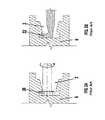
- FIG. 1is a side views of the groove of the prior art
- FIGS. 2A , and 2 Bshow side views of the prior art showing how a rotary router type cutter or a linear broach type cutter may be used to cut the sidewall grooves shown in FIG. 1 .
- FIG. 3is a side view of the groove of the present invention.
- FIGS. 4A and 4Bshows side views the various steps in which a circular saw type cutter may be used to cut the groove shown in FIG. 3 ;
- FIG. 5is a side view of the connector showing the manner in which the sub-tongues flex inward as the connector is inserted in the groove of FIG. 3 ;
- FIG. 6is a detail of the sub-tongue holding force and sub-tongue bending force components of the resultant force acting at the point of contact between the distal end of a sub-tongue and its mating groove step; and.
- FIG. 7is a side view showing forces acting on the sub-tongue arms of the connector.
- FIG. 1is a side view of the groove element of the prior art spring-loaded, split-tongue, locking connector system of applicants U.S. patent application Ser. No. 12/705,593.
- the groove 2is fabricated into the edge 4 of structural panel 6 in such a manner as to not result in the loss of panel surface 8 .
- the groove geometryhas two types of angles associated with it: angle “e”, the angle of the entrance ramp 10 relative to the groove insertion axis 13 which is the direction of tongue insertion, and angle “s”, the angle of step edge (i.e. “holding ramp”) 12 of sidewall step 14 relative to the groove insertion axis 13 .
- the groove geometryis symmetric.
- the groovehas two “e” angles and two “s” angles.
- the dotted extrapolation 16 of step edge 12intersects the opposite groove sidewall at point 18 .
- the groove geometryhas two right angles “r” near the entry of the groove.
- step edge 12i.e. “holding ramp”
- a router type cutterhas an array of uniformly shaped cutting teeth spaced symmetrically about the cutter axis of rotation.
- the step of FIG. 1can be cut using a broach type cutter 22 as shown in FIG. 2B .
- the broach type cutterhas a large number of teeth of gradually increasing depth arrayed to cut in the direction into the paper.
- the broach type cuttercuts the step by being pulled linearly through the groove in the direction into the paper.
- Both the rotary router type cutter and the linear broach type cuttercan be used to cut grooves of the shape shown in FIG. 1 .
- neither cutter typehas proven suitable due to tool heating and chip removal difficulties for groove manufacture at cutting rates required for economical commercial production.
- step edge 12 in FIG. 1must be reduced so that the dotted extrapolation 16 of the step edge (i.e. “holding ramp”) 12 no longer intersects the opposite groove sidewall.
- FIGS. 1 and 3have the same reference numerals.
- FIG. 4AThe manner in which reduction of the step angle s allows the groove to be cut using a sequence of six high speed circular saw cuts is shown in FIG. 4A .
- FIG. 6is a side view of the connector 24 modified to mate with the modified panel groove shown in FIG. 3 .
- FIG. 6shows two sub-tongues 26 extending from the left side of the connector 24 , and two sub-tongues 28 extending from the right side of connector 24 .
- Each sub-tonguehas a catch 30 at its distal end.
- Each sub-tonguehas a bending force 32 acting on its distal catch by the panel groove.
- the bending force 32acts on a moment arm 34 to bend the sub-tongues in cantilever fashion about the center beam (i.e. base support element) 34 of the connector 24 of which the right-angle corners 36 are adapted to fit into the right angles “r” of the panel groove.
- FIG. 7shows the normal force Fn and the friction force Ft acting on sub-tongue catch 30 at the point where it contacts step edge (i.e. “holding ramp”) 12 of FIG. 3 .
- the force acting normal to the side wall edgeis denoted by Fn, and the resulting friction force resisting removal of the connector from the groove is denoted by Ft in FIG. 7 .
- the bending force Fbacts normal to moment arm 34 and is at an angle of about 36.° 09° relative to the resultant force Fr.
- the horizontal holding force, Fh, holding the connector in the grooveis at an angle of about 43.3° relative to the resultant force Fr.
Landscapes
- Engineering & Computer Science (AREA)
- Architecture (AREA)
- Civil Engineering (AREA)
- Structural Engineering (AREA)
- Life Sciences & Earth Sciences (AREA)
- Wood Science & Technology (AREA)
- Joining Of Building Structures In Genera (AREA)
Abstract
Description
Claims (10)
Priority Applications (3)
| Application Number | Priority Date | Filing Date | Title |
|---|---|---|---|
| US13/086,424US9010067B2 (en) | 2011-04-14 | 2011-04-14 | Fabricating the locking steps in the groove element of spring-loaded split-tongue locking connector system |
| PCT/US2012/033839WO2012142617A1 (en) | 2011-04-14 | 2012-04-16 | Fabricating the locking steps in the groove element of spring-loaded split-tongue locking connector system |
| US14/642,679US9322421B2 (en) | 2011-04-13 | 2015-03-09 | Spring-loaded split-tongue connector system |
Applications Claiming Priority (1)
| Application Number | Priority Date | Filing Date | Title |
|---|---|---|---|
| US13/086,424US9010067B2 (en) | 2011-04-14 | 2011-04-14 | Fabricating the locking steps in the groove element of spring-loaded split-tongue locking connector system |
Related Child Applications (1)
| Application Number | Title | Priority Date | Filing Date |
|---|---|---|---|
| US14/642,679Continuation-In-PartUS9322421B2 (en) | 2011-04-13 | 2015-03-09 | Spring-loaded split-tongue connector system |
Publications (2)
| Publication Number | Publication Date |
|---|---|
| US20120260602A1 US20120260602A1 (en) | 2012-10-18 |
| US9010067B2true US9010067B2 (en) | 2015-04-21 |
Family
ID=47005342
Family Applications (1)
| Application Number | Title | Priority Date | Filing Date |
|---|---|---|---|
| US13/086,424Active - ReinstatedUS9010067B2 (en) | 2011-04-13 | 2011-04-14 | Fabricating the locking steps in the groove element of spring-loaded split-tongue locking connector system |
Country Status (2)
| Country | Link |
|---|---|
| US (1) | US9010067B2 (en) |
| WO (1) | WO2012142617A1 (en) |
Cited By (5)
| Publication number | Priority date | Publication date | Assignee | Title |
|---|---|---|---|---|
| US9908692B2 (en)* | 2015-05-06 | 2018-03-06 | ASFI Partners, L.P. | Multi-piece storage tank pad with separate connectors |
| US20200237612A1 (en)* | 2018-11-21 | 2020-07-30 | Guangdong Skg Intelligent Technology Co., Ltd | Neck massaging device |
| US20220259856A1 (en)* | 2019-06-12 | 2022-08-18 | Frank Cato Lahti | Wall-Building Element System and Building Element for Use in the System |
| USD970055S1 (en) | 2021-04-25 | 2022-11-15 | James Loughran | Modular floor panel locking system |
| US20230382000A1 (en)* | 2022-05-24 | 2023-11-30 | Black & Decker Inc. | Power tool guide and power tool guide assembly |
Families Citing this family (4)
| Publication number | Priority date | Publication date | Assignee | Title |
|---|---|---|---|---|
| DE102007062430B3 (en)* | 2007-12-20 | 2009-07-02 | Flooring Technologies Ltd. | Method for machining a side edge of a panel and apparatus for carrying out the method |
| DE102012209278B4 (en)* | 2012-06-01 | 2018-04-12 | Kgt Graphit Technologie Gmbh | susceptor |
| US9441379B2 (en) | 2014-08-27 | 2016-09-13 | Evan J. Stover | Flooring system having assembly clip and related method |
| MX2021009974A (en)* | 2019-02-26 | 2021-09-21 | Jfe Steel Corp | Gas wiping nozzle, and method for manufacturing molten metal-plated metal band. |
Citations (9)
| Publication number | Priority date | Publication date | Assignee | Title |
|---|---|---|---|---|
| US6460306B1 (en)* | 1999-11-08 | 2002-10-08 | Premark Rwp Holdings, Inc. | Interconnecting disengageable flooring system |
| US6675545B2 (en)* | 1999-12-14 | 2004-01-13 | Mannington Mills, Inc. | Connecting system for surface coverings |
| US6729091B1 (en)* | 1999-07-05 | 2004-05-04 | Pergo (Europe) Ab | Floor element with guiding means |
| US6763643B1 (en)* | 1998-10-06 | 2004-07-20 | Pergo (Europe) Ab | Flooring material comprising flooring elements which are assembled by means of separate joining elements |
| US7021019B2 (en)* | 2002-09-18 | 2006-04-04 | Kaindl Flooring Gmbh | Panels with connecting clip |
| US7677005B2 (en)* | 2002-04-03 | 2010-03-16 | Valinge Innovation Belgium Bvba | Mechanical locking system for floorboards |
| US7841145B2 (en)* | 2004-10-22 | 2010-11-30 | Valinge Innovation Ab | Mechanical locking system for panels and method of installing same |
| US7866111B2 (en)* | 2007-03-14 | 2011-01-11 | Ab Gustaf Kahr | Profiled rail and floorboard for flooring system |
| US7908816B2 (en)* | 2003-03-24 | 2011-03-22 | Kronotec Ag | Device for connecting building boards, especially floor panels |
Family Cites Families (7)
| Publication number | Priority date | Publication date | Assignee | Title |
|---|---|---|---|---|
| DE3908851A1 (en)* | 1989-03-17 | 1990-09-20 | Peter Schacht | METHOD FOR PRODUCING MULTI-LAYER PANEL BOARDS PREFERRED FOR FLOORS |
| US5295341A (en)* | 1992-07-10 | 1994-03-22 | Nikken Seattle, Inc. | Snap-together flooring system |
| BE1010487A6 (en)* | 1996-06-11 | 1998-10-06 | Unilin Beheer Bv | FLOOR COATING CONSISTING OF HARD FLOOR PANELS AND METHOD FOR MANUFACTURING SUCH FLOOR PANELS. |
| WO1998026399A2 (en)* | 1996-11-27 | 1998-06-18 | Alu, Inc. | Modular display system of interlocking components |
| US6449918B1 (en)* | 1999-11-08 | 2002-09-17 | Premark Rwp Holdings, Inc. | Multipanel floor system panel connector with seal |
| US6761008B2 (en)* | 1999-12-14 | 2004-07-13 | Mannington Mills, Inc. | Connecting system for surface coverings |
| US8181407B2 (en)* | 2002-05-03 | 2012-05-22 | Faus Group | Flooring system having sub-panels |
- 2011
- 2011-04-14USUS13/086,424patent/US9010067B2/enactiveActive - Reinstated
- 2012
- 2012-04-16WOPCT/US2012/033839patent/WO2012142617A1/enactiveApplication Filing
Patent Citations (10)
| Publication number | Priority date | Publication date | Assignee | Title |
|---|---|---|---|---|
| US6763643B1 (en)* | 1998-10-06 | 2004-07-20 | Pergo (Europe) Ab | Flooring material comprising flooring elements which are assembled by means of separate joining elements |
| US6729091B1 (en)* | 1999-07-05 | 2004-05-04 | Pergo (Europe) Ab | Floor element with guiding means |
| US6460306B1 (en)* | 1999-11-08 | 2002-10-08 | Premark Rwp Holdings, Inc. | Interconnecting disengageable flooring system |
| US6769217B2 (en)* | 1999-11-08 | 2004-08-03 | Premark Rwp Holdings, Inc. | Interconnecting disengageable flooring system |
| US6675545B2 (en)* | 1999-12-14 | 2004-01-13 | Mannington Mills, Inc. | Connecting system for surface coverings |
| US7677005B2 (en)* | 2002-04-03 | 2010-03-16 | Valinge Innovation Belgium Bvba | Mechanical locking system for floorboards |
| US7021019B2 (en)* | 2002-09-18 | 2006-04-04 | Kaindl Flooring Gmbh | Panels with connecting clip |
| US7908816B2 (en)* | 2003-03-24 | 2011-03-22 | Kronotec Ag | Device for connecting building boards, especially floor panels |
| US7841145B2 (en)* | 2004-10-22 | 2010-11-30 | Valinge Innovation Ab | Mechanical locking system for panels and method of installing same |
| US7866111B2 (en)* | 2007-03-14 | 2011-01-11 | Ab Gustaf Kahr | Profiled rail and floorboard for flooring system |
Cited By (7)
| Publication number | Priority date | Publication date | Assignee | Title |
|---|---|---|---|---|
| US9908692B2 (en)* | 2015-05-06 | 2018-03-06 | ASFI Partners, L.P. | Multi-piece storage tank pad with separate connectors |
| US20200237612A1 (en)* | 2018-11-21 | 2020-07-30 | Guangdong Skg Intelligent Technology Co., Ltd | Neck massaging device |
| US11890254B2 (en)* | 2018-11-21 | 2024-02-06 | Guangdong Skg Intelligent Technology Co., Ltd | Neck massaging device |
| US20220259856A1 (en)* | 2019-06-12 | 2022-08-18 | Frank Cato Lahti | Wall-Building Element System and Building Element for Use in the System |
| US12291865B2 (en)* | 2019-06-12 | 2025-05-06 | Frank Cato Lahti | Wall-building element system and building element for use in the system |
| USD970055S1 (en) | 2021-04-25 | 2022-11-15 | James Loughran | Modular floor panel locking system |
| US20230382000A1 (en)* | 2022-05-24 | 2023-11-30 | Black & Decker Inc. | Power tool guide and power tool guide assembly |
Also Published As
| Publication number | Publication date |
|---|---|
| US20120260602A1 (en) | 2012-10-18 |
| WO2012142617A1 (en) | 2012-10-18 |
Similar Documents
| Publication | Publication Date | Title |
|---|---|---|
| US9010067B2 (en) | Fabricating the locking steps in the groove element of spring-loaded split-tongue locking connector system | |
| KR102149416B1 (en) | Method for producing a mechanical locking system for building panels | |
| US9951526B2 (en) | Mechanical locking system for building panels | |
| KR101265878B1 (en) | Panel, in particular floor panel | |
| US10125488B2 (en) | Building panel with a mechanical locking system | |
| JP6132207B2 (en) | Terminal fittings and connectors | |
| US9322421B2 (en) | Spring-loaded split-tongue connector system | |
| EP2524093B1 (en) | Mechanical locking system for floor panels | |
| JP6061198B2 (en) | connector | |
| US10014618B2 (en) | Connector with terminal position assurance | |
| JP6008250B2 (en) | connector | |
| KR102149414B1 (en) | Building panel with a mechanical locking system | |
| CN112012426B (en) | Opposite-embedded type lock catch plate and buckling method | |
| JP6344316B2 (en) | connector | |
| CN101488608B (en) | A connector device and locking structure | |
| JP3900958B2 (en) | connector | |
| JP2003243065A (en) | Connector and male terminal metal piece | |
| JP6599151B2 (en) | Backlash structure of multilayer connector | |
| JP2003243080A (en) | Connector | |
| US9698526B2 (en) | Connector with aligning plate | |
| JP2007311301A (en) | Pack battery | |
| RU2601263C2 (en) | Detachable connection | |
| EP3268554B1 (en) | A spring-loaded split-tongue connector system | |
| JP4857899B2 (en) | connector | |
| CN1645677A (en) | Connector |
Legal Events
| Date | Code | Title | Description |
|---|---|---|---|
| STCF | Information on status: patent grant | Free format text:PATENTED CASE | |
| FEPP | Fee payment procedure | Free format text:MAINTENANCE FEE REMINDER MAILED (ORIGINAL EVENT CODE: REM.); ENTITY STATUS OF PATENT OWNER: SMALL ENTITY | |
| LAPS | Lapse for failure to pay maintenance fees | Free format text:PATENT EXPIRED FOR FAILURE TO PAY MAINTENANCE FEES (ORIGINAL EVENT CODE: EXP.); ENTITY STATUS OF PATENT OWNER: SMALL ENTITY | |
| STCH | Information on status: patent discontinuation | Free format text:PATENT EXPIRED DUE TO NONPAYMENT OF MAINTENANCE FEES UNDER 37 CFR 1.362 | |
| FP | Lapsed due to failure to pay maintenance fee | Effective date:20190421 | |
| FEPP | Fee payment procedure | Free format text:SURCHARGE, PETITION TO ACCEPT PYMT AFTER EXP, UNINTENTIONAL (ORIGINAL EVENT CODE: M3558); ENTITY STATUS OF PATENT OWNER: SMALL ENTITY Free format text:PETITION RELATED TO MAINTENANCE FEES FILED (ORIGINAL EVENT CODE: PMFP); ENTITY STATUS OF PATENT OWNER: SMALL ENTITY | |
| MAFP | Maintenance fee payment | Free format text:PAYMENT OF MAINTENANCE FEE, 4TH YEAR, MICRO ENTITY (ORIGINAL EVENT CODE: M3551); ENTITY STATUS OF PATENT OWNER: SMALL ENTITY Year of fee payment:4 | |
| FEPP | Fee payment procedure | Free format text:PETITION RELATED TO MAINTENANCE FEES DISMISSED (ORIGINAL EVENT CODE: PMFS); ENTITY STATUS OF PATENT OWNER: SMALL ENTITY | |
| FEPP | Fee payment procedure | Free format text:PETITION RELATED TO MAINTENANCE FEES FILED (ORIGINAL EVENT CODE: PMFP); ENTITY STATUS OF PATENT OWNER: SMALL ENTITY | |
| FEPP | Fee payment procedure | Free format text:PETITION RELATED TO MAINTENANCE FEES GRANTED (ORIGINAL EVENT CODE: PMFG); ENTITY STATUS OF PATENT OWNER: SMALL ENTITY | |
| PRDP | Patent reinstated due to the acceptance of a late maintenance fee | Effective date:20210830 | |
| STCF | Information on status: patent grant | Free format text:PATENTED CASE | |
| FEPP | Fee payment procedure | Free format text:MAINTENANCE FEE REMINDER MAILED (ORIGINAL EVENT CODE: REM.); ENTITY STATUS OF PATENT OWNER: SMALL ENTITY | |
| AS | Assignment | Owner name:ENGINEERED FLOORS, LLC, GEORGIA Free format text:ASSIGNMENT OF ASSIGNORS INTEREST;ASSIGNORS:BAKER, GEOFFREY ALAN;VITALE, NICHOLAS GERRARD;SIGNING DATES FROM 20230301 TO 20230306;REEL/FRAME:063358/0590 | |
| FEPP | Fee payment procedure | Free format text:7.5 YR SURCHARGE - LATE PMT W/IN 6 MO, LARGE ENTITY (ORIGINAL EVENT CODE: M1555); ENTITY STATUS OF PATENT OWNER: LARGE ENTITY Free format text:ENTITY STATUS SET TO UNDISCOUNTED (ORIGINAL EVENT CODE: BIG.); ENTITY STATUS OF PATENT OWNER: LARGE ENTITY | |
| MAFP | Maintenance fee payment | Free format text:PAYMENT OF MAINTENANCE FEE, 8TH YEAR, LARGE ENTITY (ORIGINAL EVENT CODE: M1552); ENTITY STATUS OF PATENT OWNER: LARGE ENTITY Year of fee payment:8 |