US9009319B2 - Optimizing allocation of on-demand resources using performance - Google Patents
Optimizing allocation of on-demand resources using performanceDownload PDFInfo
- Publication number
- US9009319B2 US9009319B2US13/352,852US201213352852AUS9009319B2US 9009319 B2US9009319 B2US 9009319B2US 201213352852 AUS201213352852 AUS 201213352852AUS 9009319 B2US9009319 B2US 9009319B2
- Authority
- US
- United States
- Prior art keywords
- customer
- performance
- performance zone
- resource
- resources
- Prior art date
- Legal status (The legal status is an assumption and is not a legal conclusion. Google has not performed a legal analysis and makes no representation as to the accuracy of the status listed.)
- Active, expires
Links
Images


Classifications
- H—ELECTRICITY
- H04—ELECTRIC COMMUNICATION TECHNIQUE
- H04L—TRANSMISSION OF DIGITAL INFORMATION, e.g. TELEGRAPHIC COMMUNICATION
- H04L41/00—Arrangements for maintenance, administration or management of data switching networks, e.g. of packet switching networks
- H04L41/50—Network service management, e.g. ensuring proper service fulfilment according to agreements
- H04L41/5041—Network service management, e.g. ensuring proper service fulfilment according to agreements characterised by the time relationship between creation and deployment of a service
- H04L41/5051—Service on demand, e.g. definition and deployment of services in real time
- G—PHYSICS
- G06—COMPUTING OR CALCULATING; COUNTING
- G06F—ELECTRIC DIGITAL DATA PROCESSING
- G06F9/00—Arrangements for program control, e.g. control units
- G06F9/06—Arrangements for program control, e.g. control units using stored programs, i.e. using an internal store of processing equipment to receive or retain programs
- G06F9/46—Multiprogramming arrangements
- G06F9/50—Allocation of resources, e.g. of the central processing unit [CPU]
- G06F9/5005—Allocation of resources, e.g. of the central processing unit [CPU] to service a request
- G06F9/5011—Allocation of resources, e.g. of the central processing unit [CPU] to service a request the resources being hardware resources other than CPUs, Servers and Terminals
- H—ELECTRICITY
- H04—ELECTRIC COMMUNICATION TECHNIQUE
- H04L—TRANSMISSION OF DIGITAL INFORMATION, e.g. TELEGRAPHIC COMMUNICATION
- H04L67/00—Network arrangements or protocols for supporting network services or applications
- H04L67/01—Protocols
- H04L67/10—Protocols in which an application is distributed across nodes in the network
Definitions
- Data centersare becoming more prevalent, as various institutions seek to centralize computing and data storage resources in a single location. Many such data centers are dedicated to a particular institution and can be housed in that institution's facility directly. Other data centers can be of a multi-tenant arrangement, in which various resources of different customers of the data center are present in a single data center location.
- cloud computingIn addition to these data center models, cloud computing is also becoming predominant. In general, cloud computing means that various resources can be flexibly allocated to multiple entities to provide for on-demand computing resources as needs dictate. Such entities can range from individual users to large corporations.
- the present inventioncan be used to efficiently allocate on-demand resources to a customer of a data center such as a multi-tenant data center having resources dedicated to given customers, as well as non-dedicated and on-demand resources that can be flexibly provisioned to customers.
- a data centersuch as a multi-tenant data center having resources dedicated to given customers, as well as non-dedicated and on-demand resources that can be flexibly provisioned to customers.
- the present inventionincludes a method for receiving a user request for allocation of an on-demand resource within a data center having a plurality of performance zones each logically connected by a logical network, determining whether the user request includes a performance zone request for placement in a given performance zone, and if so determining whether a resource corresponding to the requested on-demand resource is available within the requested performance zone. If this resource is available, it can be assigned to the user the resource within the requested performance zone, and otherwise the user request can be made to fail.
- a resource within a second performance zone(outside of the performance zone) can be assigned. Further, a tunnel with a predetermined bandwidth can be provided between this resource and another resource of the user within the performance zone. Even though these resources are in different performance zones, they can appear to the user as a single logical network.
- Another aspect of the present inventionis directed to a system that includes an access layer having multiple server collections, an aggregation layer having first switching devices each coupled to a portion of the server collections, and a core layer including second switching devices each coupled to a portion of the first switching devices.
- the systemcan further include multiple performance zones that each is a logical collection of the portion of server collections coupled to the same first switching device. Note that communications within a performance zone may be optimized as compared to communications between performance zones.
- the systemmay include logical switches, each represented by a table for a customer.
- Such tablecan include entries, each of which associates an on-demand resource of the customer to a performance zone identifier corresponding to a given performance zone. Via this logical switch the customer can view on-demand resources of the customer located in different performance zones as a single logical network.
- the systemmay further include a scheduler to dynamically allocate an on-demand resource requested by a customer on a server of a first performance zone, where the customer is associated with a performance zone identifier for that performance zone.
- the schedulermay weight a request by the customer for allocation within this performance zone with a first value and weight a second allocation criteria with a second value, and schedule the resource to the first performance zone based on the weighted allocation request and the weighted second allocation criteria.
- This resourcemay be allocated with a quality of service (QoS) guarantee when it is allocated within the first performance zone and without a QoS guarantee when not allocated within this performance zone.
- QoSquality of service
- Yet another aspect of the present inventionis directed to a multi-tenant data center.
- This data centercan include a number of hosts (e.g., each a server) that can be grouped into different server collections. Each of these server collections may be coupled to a switch of an aggregation layer, which in turn is coupled to switches of a core layer.
- a customer of the data centermay be provided a logical performance zone in which on-demand resources allocated to the customer appear to the customer as a single logical network having a given QoS. Note that at least some of these resources can be located in different ones of the server collections.
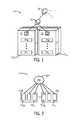
- FIG. 1is a physical view of a portion of a data center in accordance with one embodiment of the present invention.
- FIG. 2is an illustration of a block diagram of a logical network in accordance with an embodiment of the present invention.
- FIG. 3is a block diagram of a logical network view of computing resources in accordance with an embodiment of the present invention.
- FIG. 4is a physical view of a data center and a logical view of resources allocated to a given customer within a data center in accordance with one embodiment of the present invention.
- FIG. 5is a flow diagram of provisioning of on-demand resources for a customer in accordance with one embodiment of the present invention.
- FIG. 1shown is a physical view of a portion of a data center.
- a networkincludes many different types of computing resources, storage resources, switching resources, networking resources and so forth.
- the view of FIG. 1is limited to compute resources, namely a plurality of servers 34 (generally).
- individual servers 34 0 - 34 ncan be configured in a cabinet 30 .
- a switch and/or router 32may be present.
- servers 34can be configured as rack-based servers and may take various forms, including blade-type servers, rack-mounted servers, chassis-enclosed servers and so forth.
- Each servermay generally include at least a processor, memory, network interface circuitry, and mass storage.
- a collection of servers present in multiple cabinetscan form a huddle 20 , which corresponds to a collection of physical servers present in one or more cabinets within a data center that share a substantially homogenous configuration of network, compute, and management capabilities.
- a huddlemay be formed of servers present in a given number of cabinets.
- a huddlecan be formed of servers present within 10 cabinets.
- each cabinetcan be configured with 20 servers.
- a huddlecan include a collection of 200 servers in this example.
- multiple huddles 20 a - 20 xmay be present in an access layer.
- each of the huddlescan communicate upstream to an aggregation layer that can include multiple switches 40 .
- communication between different cabinets within huddles of an access layercan occur using switches 40 (and in-cabinet switch 32 ).
- communications with agents outside of this set of huddlescan occur via an upstream connection through a core layer, which may include a plurality of switches 50 .
- a core layerwhich may include a plurality of switches 50 .
- multiple switches of the core layercan be interconnected together, and furthermore multiple switches of the aggregation layer can communicate with a single switch of the core layer.
- latencies and capacitycan exist with reference to traffic within a huddle, contained to one cabinet; traffic within a huddle traversing between two separate cabinets (same aggregation device); traffic between huddles traversing between two separate cabinets (same aggregation device); traffic between huddles traversing between two separate cabinets, each cabinet connected to a different aggregation point; and traffic between huddles located in different data centers.
- each server within a cabinetincludes a network interface controller (NIC) that can communicate at a bandwidth of 1 gigabits per second (Gbps).
- NICnetwork interface controller
- the upstream channel coupled between the access layer and the aggregation layere.g., between switch 32 and switch 40
- this upstream channelcan be oversubscribed if much of the communications occurring within the servers of the cabinet are directed to entities outside the cabinet.
- multiple upstream channels from different cabinetsare coupled to switches 40 of the aggregation layer.
- the upstream channel between these switches 40 and the switches 50 of the core layermay be limited to a bandwidth of, e.g., 10 Gbps. Again, when communications are directed to entities outside this aggregation layer, upstream bandwidth can be oversubscribed.
- resources within a cabinetcan become stranded, namely unused or unallocated for at least some amounts of time. That is, in a multi-tenant data center, typically all servers within a cabinet are associated with a single client such that all the servers within the cabinet are dedicated to that client. When a client or customer has not fully purchased the amount of servers present in a cabinet, typically the remaining servers (if present) cannot be allocated to other customers. And, space must remain available for the customer to be able to insert additional resources over time as the customer's compute needs increase. Furthermore, when dynamically allocating additional compute resources to a client, those resources are typically included in the same cabinet as the client's other compute resources, or at least in the same huddle.
- a single customer's compute resourcesare typically assigned to a single huddle.
- compute resource space within a cabinetlimited, so too is the amount of space in a huddle limited to provide for future growth in compute resources for the customers within the huddle.
- compute resources of a single customerif they are to share a single Internet protocol (IP) address, are to be maintained in a single huddle.
- IPInternet protocol
- a multi-tenant data centermay further include a so-called cloud domain, in which additional resources for a customer can be provided on an as-needed, on-demand basis.
- cloud domainin which additional resources for a customer can be provided on an as-needed, on-demand basis.
- a single physical servermay accommodate multiple virtual machines (VMs), each of which can be associated with a different customer of the data center.
- VMsvirtual machines
- the cloud compute domainmultiple customers each can have associated with it one or more virtual machines housed in a single physical server.
- embodimentsintroduce the concept of logical networks formed of different performance zones.
- policiescan be set to provision additional resources for a given customer such that these resources (including on-demand resources) within different physical cabinets, racks or other enclosures of a data center can be more efficiently utilized.
- embodimentsmay enable additional compute resources to be allocated to a customer over time, where these compute resources need not be included in a same cabinet or even same huddle as other compute resources of the customer.
- FIG. 2illustrates a block diagram of a logical network in accordance with an embodiment of the present invention.
- a logical view of a data center 100may include multiple performance zones PZ 0 -PZn. Within each performance zone multiple virtual machines 110 0 - 110 x may be provided. And the different performance zones can couple together via a logical network 120 .
- FIG. 2shows a logical view of a data center.
- the translation between physical components within a data center and logical componentsmay be by way of one or more mapping tables that map physical resources to corresponding logical resources.
- multiple logical devicessuch as multiple virtual machines can be configured on a single physical device such as a single physical server.
- performance zoneis defined as a collection of logical resources within a constrained logical portion of a logical network environment. By configuring different logical resources for a single customer within a single performance zone, optimized processing can be realized, in that a single performance zone provides processing with reduced latency.
- individual virtual machines 110can be present within one or more physical servers.
- individual performance zones PZcan also be present within one or more physical servers. More typically, in various implementations a single performance zone may include a variety of logical devices located within multiple physical servers or other physical devices.
- a typical performance zonemay constitute a collection of logical devices within multiple cabinets, and even multiple huddles.
- a given performance zonecan span arbitrarily over physical devices of a data center such that a performance zone can extend beyond the physical constraints of a network for a given tenant of the data center, e.g., via dedicated tunnels with guaranteed performance.
- logical network 200can be formed of a collection of physical devices 210 0 - 210 n .
- each physical device 210may correspond to a physical host such as a physical server that includes various compute resources such as one or more processors, networking components, memory, storage and so forth.
- Each of these host physical servers or hosts 210can include various hardware, firmware and software. For purposes of illustration, assume that each host 210 includes at least one hypervisor to execute thereon.
- a hypervisormay communicate with a virtual switch of the host that in turn can be coupled to multiple virtual machines, on which different applications or other user software can execute. Also in this logical network configuration, computing resources such as VMs of multiple clients can be present within a single host.
- each physical host 210 within a performance zonecan include a virtual switch 215 to be directly connected (that is, by a point-to-point connection) to a corresponding virtual switch of each other host within the performance zone.
- the virtual switchesthus are used to communicate internally within a server between hypervisor and VMs.
- the interconnections between virtual switchescollectively can be viewed by a customer as a logical switch of a given network of the customer. That is, a logical switch acts as a customer abstraction to present interconnection of virtual switches of disparate hosts to appear as a single logical network, regardless of actual physical location of the hosts.
- each host 210can be present within a single cabinet, or the hosts can be present in different cabinets.
- each host 210can be associated with one or more logical switches to provide for interconnection between the different hosts within one or more performance zones.
- such logical switchescan be implemented in part as a table that includes entries to provide a mapping between a given host and other hosts. Note that in some embodiments the mapping of which VMs are associated with which logical switches can be held external to the actual virtual or physical switches that exist in the data path. Some examples of these would be an OpenFlow controller, or a LISP mapping database.
- OpenFlow controllerall knowledge of how VMs communicate with each other over a logical switch is housed outside of the network. The necessary paths or logical ‘wiring’ to enable data communication between the VMs is provided to the virtual switch contained within each affected hypervisor. In OpenFlow, these paths are called flows.
- the hypervisoris aware that its guest VMs are participating in a LISP domain.
- the hypervisorcan query an externally located mapping database in order to determine how to encapsulate the guest VMs' traffic in order to direct it to the proper destination hypervisor. The destination hypervisor will then decapsulate the traffic and deliver it to the destination VM.
- each performance zone shown in FIG. 3includes 6 individual hosts. However, understand that the scope of the present invention is not limited this regard, and typically many more individual hosts may be present in a given performance zone. For example, in some implementations between approximately 10 and 50,000 hosts may be present in each performance zone, and the number of VMs executing in each host can also vary significantly.
- a logical aggregation layerwhich may be formed of physical switches 230 , may couple together the different performances zones. Note that although only two performance zones are shown in the embodiment of FIG. 3 , understand the scope of the present invention is not limited in this regard. In many implementations such as in a data center greater than two such performance zones may couple together via a logical aggregation layer.
- FIG. 3shows that within the performance zones themselves, database resources 250 0 - 250 n can be provided.
- database resources 250 0 - 250 ncan be provided.
- DBaaSdatabase as a service
- the database resourcescan take the form of various storage mechanisms such as associated with certain servers within the performance zone or, e.g., a storage area network (SAN) coupled to one or more of the hosts within the performance zone.
- SANstorage area network
- additional on-demand resourcesnamely an external SAN 240 may be present and which can be accessed via switches 230 n that in turn couple through switches 230 1 to switches 230 0 .
- switches 230 1can correspond to a core layer while switches 230 n can correspond to another access layer.
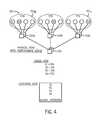
- FIG. 4shows a high-level view of a data center architecture. More specifically, FIG. 4 shows a physical view of a data center 300 and a logical view of resources allocated to a given customer within the data center, both from a logical view and the customer's view of the logical network.
- architecture 300may include a plurality of huddles 310 0 - 310 x . As discussed above, each huddle may include a collection of physical servers configured in one or multiple racks or other cabinets. For purposes of illustration assume that four servers are assigned to a given customer.
- each of the serversis present in a different huddle.
- the first two serversnamely servers S 1 and S 2
- the first two serversare present within huddles of a single performance zone, PZA.
- third server, S 3is assigned within a different performance zone, PZB
- a fourth server S 4is assigned within yet a different performance zone PZC. Accordingly, better communication performance between servers of this single customer can be achieved between servers S 1 and S 2 , as they are present within a single performance zone.
- multiple individual huddlescan be coupled together at an aggregation layer by physical switches 320 a - 320 c .
- the collections of huddles below the aggregation layerconstitutes an access layer, while the switches 320 may be of the aggregation layer.
- communications between servers of these different huddles coupled to different physical switches 320may communicate through a core layer that includes multiple physical switches 330 .
- servers S 1 and S 2are present in the same performance zone PZA, while servers S 3 and S 4 are present in different performance zones, namely zones PZB and PZC.
- a customer's view of the data centermay be as a single logical network that includes all of its servers.
- the performance zone conceptcan be abstracted away from the customer, in some embodiments.
- the aggregation and core physical network layerscan include technologies such as MPLS-TE based upon RSVP.
- thismay trigger an event that auto-creates a 100 Mbps network reservation, via tunnels, that allows this tenant to span beyond the physical PZ boundary yet still be presented with a single logical or customer-level performance zone.
- the concept of performance zonescan be used in connection with provisioning of on-demand resources within a data center to flexibly assign resources to a customer.
- provisioningmay take into account the availability of performance zones within the data center and seek to optimize provisioning of resources by placing on-demand resources requested by a customer within a single performance zone.
- certain quality of service assurancescan be provided for communications and computing tasks for the customer given this optimized placement of the on-demand resources.
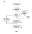
- FIG. 5shown is a flow diagram of provisioning of on-demand resources for a customer. More specifically, FIG. 5 shows a method 400 that can be used in connection with a provisioning or scheduling algorithm within a data center to allow a customer's request for an on-demand resource to be granted and a given resource to be allocated to that customer.
- method 400can be executed on one or more servers, which can be part of a scheduling complex of the data center.
- Examples of on-demand resources that can be requested and allocated in accordance with an embodiment of the present inventioninclude compute resources such as server resources that can be implemented as one or more VMs, storage resources such as a block storage, e.g., according to a storage area network (SAN) or file storage according to a network attached storage (NAS), database resources, load balancer resources, switching resources and so forth.
- method 400may begin by receiving a user request for an on-demand resource (block 410 ).
- a scheduling algorithmmay enable a customer to provide a performance zone request with a resource request (e.g., including a performance zone identifier associated with the customer).
- a resource requeste.g., including a performance zone identifier associated with the customer.
- such performance zone requestis optional, and it can be assumed in many instances that a customer wishes to have its resource placed within one or more performance zones having a number of other resources of the customer.
- a resourceis available within the requested performance zone.
- the resource requestedis an on-demand computing resource that can be fulfilled by provisioning of a virtual machine.
- Assignment of resourcescan be according to various scheduling algorithms. For example, in one embodiment a scheduling algorithm can execute a first pass to eliminate or cull some amount of available resources out of the scheduling decision. This culling or elimination of possible placement of an allocated resource can take different forms. For example, in a data center having 100 huddles, the elimination process may, according to some flexible criteria, eliminate half of the huddles from consideration in a scheduling algorithm. In a second phase of the scheduling, the remaining resources can be analyzed to determine the appropriate location for the requested resource.
- allocation criteriacan include capabilities of the performance zone such as accessibility to external resources including shared storage, backups, access to customer dedicated circuits, geographical location, availability of higher memory instances, availability of specific types of resources (e.g., GPU, SSD, Infiniband, higher host network capacity, etc.).
- capabilities of the performance zonesuch as accessibility to external resources including shared storage, backups, access to customer dedicated circuits, geographical location, availability of higher memory instances, availability of specific types of resources (e.g., GPU, SSD, Infiniband, higher host network capacity, etc.).
- Yet another type of criteriacan be an anti-affinity calculation used for business continuity purposes (e.g., place VM_Y far away from VM_X).
- Each of these allocation criteriacan be weighed with a different weight.
- a performance zone criteriameaning a preference to provision resources within a single physical performance zone, can be weighted highest, although the performance zone criteria can be weighted differently in other implementations.
- a requested resourcecan be provided in a different performance zone, and an indication of this different performance zone can be communicated to the user.
- the virtual machinecan be spun up and initial state information can be provided to the virtual machine.
- state informationcan include passwords, predetermined users, predetermined connections to specific logical networks (and IP allocations on the virtual interfaces associated with each one), predetermined connections to specific external storage repositories and so forth).
- the communication back to the userit can be as simple as a confirmation that the requested resource has been allocated.
- the communicationcan include identification information to enable communications to be directed to the resource.
- this identification informationmay correspond to actions occurring outside of the VM, which can include logically wiring the VM's interfaces to participate in the proper logical switches (e.g., via OpenFlow, LISP, or other technologies), requesting and routing any required IP addresses, applying any requested firewall policies and QoS parameters to the logical ports the VM will use and so forth.
- customer management portals, billing, monitoring, or any notification based orchestration enginescan receive provisioning “success” messages and process them within their systems. Although shown with this particular illustration in the embodiment of FIG. 5 , understand the scope of the present invention is not limited in this regard.
- Embodimentsmay be implemented in code and may be stored on a storage medium having stored thereon instructions which can be used to program a system to perform the instructions.
- the storage mediummay include, but is not limited to, any type of non-transitory storage medium suitable for storing electronic instructions.
Landscapes
- Engineering & Computer Science (AREA)
- Software Systems (AREA)
- Theoretical Computer Science (AREA)
- Computer Networks & Wireless Communication (AREA)
- Signal Processing (AREA)
- Physics & Mathematics (AREA)
- General Engineering & Computer Science (AREA)
- General Physics & Mathematics (AREA)
- Data Exchanges In Wide-Area Networks (AREA)
Abstract
Description
Claims (8)
Priority Applications (3)
| Application Number | Priority Date | Filing Date | Title |
|---|---|---|---|
| US13/352,852US9009319B2 (en) | 2012-01-18 | 2012-01-18 | Optimizing allocation of on-demand resources using performance |
| US14/644,373US9992077B2 (en) | 2012-01-18 | 2015-03-11 | Optimizing allocation of on-demand resources using performance zones |
| US15/996,991US20190044833A1 (en) | 2012-01-18 | 2018-06-04 | Optimizing allocation of on-demand resources using performance zones |
Applications Claiming Priority (1)
| Application Number | Priority Date | Filing Date | Title |
|---|---|---|---|
| US13/352,852US9009319B2 (en) | 2012-01-18 | 2012-01-18 | Optimizing allocation of on-demand resources using performance |
Related Child Applications (1)
| Application Number | Title | Priority Date | Filing Date |
|---|---|---|---|
| US14/644,373DivisionUS9992077B2 (en) | 2012-01-18 | 2015-03-11 | Optimizing allocation of on-demand resources using performance zones |
Publications (2)
| Publication Number | Publication Date |
|---|---|
| US20130185436A1 US20130185436A1 (en) | 2013-07-18 |
| US9009319B2true US9009319B2 (en) | 2015-04-14 |
Family
ID=48780787
Family Applications (3)
| Application Number | Title | Priority Date | Filing Date |
|---|---|---|---|
| US13/352,852Active2032-09-16US9009319B2 (en) | 2012-01-18 | 2012-01-18 | Optimizing allocation of on-demand resources using performance |
| US14/644,373Active2032-06-24US9992077B2 (en) | 2012-01-18 | 2015-03-11 | Optimizing allocation of on-demand resources using performance zones |
| US15/996,991AbandonedUS20190044833A1 (en) | 2012-01-18 | 2018-06-04 | Optimizing allocation of on-demand resources using performance zones |
Family Applications After (2)
| Application Number | Title | Priority Date | Filing Date |
|---|---|---|---|
| US14/644,373Active2032-06-24US9992077B2 (en) | 2012-01-18 | 2015-03-11 | Optimizing allocation of on-demand resources using performance zones |
| US15/996,991AbandonedUS20190044833A1 (en) | 2012-01-18 | 2018-06-04 | Optimizing allocation of on-demand resources using performance zones |
Country Status (1)
| Country | Link |
|---|---|
| US (3) | US9009319B2 (en) |
Cited By (6)
| Publication number | Priority date | Publication date | Assignee | Title |
|---|---|---|---|---|
| US20170048268A1 (en)* | 2013-05-31 | 2017-02-16 | Catbird Networks, Inc. | Systems and methods for dynamic network security control and configuration |
| US9769174B2 (en) | 2013-06-14 | 2017-09-19 | Catbird Networks, Inc. | Systems and methods for creating and modifying access control lists |
| US9912549B2 (en) | 2013-06-14 | 2018-03-06 | Catbird Networks, Inc. | Systems and methods for network analysis and reporting |
| US10205736B2 (en) | 2017-02-27 | 2019-02-12 | Catbird Networks, Inc. | Behavioral baselining of network systems |
| US10728251B2 (en) | 2014-09-05 | 2020-07-28 | Catbird Networks, Inc. | Systems and methods for creating and modifying access control lists |
| US11196636B2 (en) | 2013-06-14 | 2021-12-07 | Catbird Networks, Inc. | Systems and methods for network data flow aggregation |
Families Citing this family (30)
| Publication number | Priority date | Publication date | Assignee | Title |
|---|---|---|---|---|
| US9075643B2 (en)* | 2012-01-23 | 2015-07-07 | International Business Machines Corporation | Automatically selecting optimal transport protocol in a cloud computing environment |
| US9001651B2 (en)* | 2012-02-06 | 2015-04-07 | Verizon Patent And Licensing Inc. | Method for call admission control in MPLS networks |
| US9992306B2 (en)* | 2012-12-21 | 2018-06-05 | E*Trade Financial Corporation | Dynamic execution |
| US10097989B2 (en) | 2012-12-21 | 2018-10-09 | E*Trade Financial Corporation | Dynamic communication |
| US9274824B2 (en)* | 2013-06-27 | 2016-03-01 | Verizon Patent And Licensing Inc. | Network technology standard operating environment |
| US10372483B2 (en) | 2014-01-20 | 2019-08-06 | Hewlett-Packard Development Company, L.P. | Mapping tenat groups to identity management classes |
| WO2015108537A1 (en) | 2014-01-20 | 2015-07-23 | Hewlett-Packard Development Company, L.P. | Identity information including a schemaless portion |
| CN105917309B (en) | 2014-01-20 | 2020-02-07 | 惠普发展公司,有限责任合伙企业 | Determining permissions of a first tenant with respect to a second tenant |
| US11809451B2 (en) | 2014-02-19 | 2023-11-07 | Snowflake Inc. | Caching systems and methods |
| CN105099950B (en)* | 2014-04-17 | 2018-08-14 | 华为技术有限公司 | A kind of resource allocation methods, message communication method and device |
| US20150370674A1 (en)* | 2014-06-19 | 2015-12-24 | Microsoft Corporation | Tenant provisioning for testing a production multi-tenant service |
| US10305761B2 (en)* | 2014-07-31 | 2019-05-28 | Corent Technology, Inc. | Multi-application SaaS metering engine |
| US10148738B2 (en)* | 2014-11-12 | 2018-12-04 | Zuora, Inc. | System and method for equitable processing of asynchronous messages in a multi-tenant platform |
| US11336519B1 (en)* | 2015-03-10 | 2022-05-17 | Amazon Technologies, Inc. | Evaluating placement configurations for distributed resource placement |
| US10084648B2 (en)* | 2015-03-12 | 2018-09-25 | International Business Machines Corporation | Creating new cloud resource instruction set architecture |
| US10911263B2 (en)* | 2016-09-28 | 2021-02-02 | Amazon Technologies, Inc. | Programmatic interfaces for network health information |
| US10862777B2 (en) | 2016-09-28 | 2020-12-08 | Amazon Technologies, Inc. | Visualization of network health information |
| US10917324B2 (en) | 2016-09-28 | 2021-02-09 | Amazon Technologies, Inc. | Network health data aggregation service |
| CN109002342B (en)* | 2017-06-07 | 2022-09-23 | 中国科学院信息工程研究所 | A method and system for oriented scheduling of computing resources based on OpenStack |
| US11323315B1 (en)* | 2017-11-29 | 2022-05-03 | Amazon Technologies, Inc. | Automated host management service |
| US10853460B2 (en) | 2017-12-04 | 2020-12-01 | Vapor IO Inc. | Modular data center |
| US10776173B1 (en) | 2018-04-30 | 2020-09-15 | Amazon Technologies, Inc. | Local placement of resource instances in a distributed system |
| US20190044812A1 (en)* | 2018-09-13 | 2019-02-07 | Intel Corporation | Technologies for dynamically selecting resources for virtual switching |
| US10951479B1 (en)* | 2018-11-27 | 2021-03-16 | Amazon Technologies, Inc. | User controlled fault domains |
| US11483246B2 (en)* | 2020-01-13 | 2022-10-25 | Vmware, Inc. | Tenant-specific quality of service |
| US11539633B2 (en) | 2020-08-31 | 2022-12-27 | Vmware, Inc. | Determining whether to rate limit traffic |
| US11799784B2 (en) | 2021-06-08 | 2023-10-24 | Vmware, Inc. | Virtualized QoS support in software defined networks |
| US12386664B2 (en) | 2021-07-14 | 2025-08-12 | International Business Machines Corporation | Determining optimal data access for deep learning applications on a cluster |
| US20250190937A1 (en)* | 2023-12-11 | 2025-06-12 | At&T Intellectual Property I, L.P. | Communication network resource allocation via segmented demand forecasting |
| US20250202836A1 (en)* | 2023-12-13 | 2025-06-19 | Microsoft Technology Licensing, Llc | Algorithm and differentiated weights for resource constrained processes |
Citations (14)
| Publication number | Priority date | Publication date | Assignee | Title |
|---|---|---|---|---|
| US20030182413A1 (en)* | 2000-06-02 | 2003-09-25 | Allen Matthew Robert | System and method for selecting a service provider |
| US20030191857A1 (en)* | 2001-10-18 | 2003-10-09 | Terrell William C. | Router and methods using in-band link between managing processor and routing processor |
| US6922724B1 (en)* | 2000-05-08 | 2005-07-26 | Citrix Systems, Inc. | Method and apparatus for managing server load |
| US7603671B2 (en)* | 2005-11-04 | 2009-10-13 | Sun Microsystems, Inc. | Performance management in a virtual computing environment |
| US7643468B1 (en)* | 2004-10-28 | 2010-01-05 | Cisco Technology, Inc. | Data-center network architecture |
| US20100020806A1 (en) | 2008-07-22 | 2010-01-28 | Amin Vahdat | Scalable Commodity Data Center Network Architecture |
| US20100131957A1 (en)* | 2007-04-13 | 2010-05-27 | Nobuharu Kami | Virtual computer system and its optimization method |
| US7787414B2 (en)* | 2005-07-12 | 2010-08-31 | Cisco Technology, Inc. | Reserving network resources for a communication session |
| US8032914B2 (en)* | 2000-11-10 | 2011-10-04 | Rodriguez Arturo A | Systems and methods for dynamically allocating bandwidth in a digital broadband delivery system |
| US20110301998A1 (en)* | 2010-06-07 | 2011-12-08 | Vanish Talwar | Managing a network system |
| US20120134440A1 (en)* | 2010-11-29 | 2012-05-31 | Samsung Electronics Co., Ltd. | Apparatus and method for estimating channel in digital video broadcasting system |
| US20120226789A1 (en)* | 2011-03-03 | 2012-09-06 | Cisco Technology, Inc. | Hiearchical Advertisement of Data Center Capabilities and Resources |
| US8380853B2 (en)* | 2007-11-29 | 2013-02-19 | Hitachi, Ltd. | Method and apparatus for locating candidate data centers for application migration |
| US20130060966A1 (en)* | 2011-09-02 | 2013-03-07 | Alexandros Moisiadis | Method and apparatus for forming a tiered wireless local area network (wlan) server topology |
Family Cites Families (9)
| Publication number | Priority date | Publication date | Assignee | Title |
|---|---|---|---|---|
| GB2349715B (en)* | 1999-05-05 | 2003-10-01 | Mitel Corp | Quotation mechanism for service environments |
| JP3617406B2 (en)* | 2000-03-30 | 2005-02-02 | 日本電気株式会社 | Quality assurance type communication service providing method and service providing method corresponding to multi-domain and service mediating apparatus |
| US8959328B2 (en)* | 2007-11-13 | 2015-02-17 | Intel Corporation | Device, system, and method for multi-resource scheduling |
| US8640131B2 (en)* | 2008-01-18 | 2014-01-28 | Microsoft Corporation | Demand-based processor cycle allocation subsequent to equal group-based processor cycle distribution |
| US8813143B2 (en)* | 2008-02-26 | 2014-08-19 | Time Warner Enterprises LLC | Methods and apparatus for business-based network resource allocation |
| CN102726007B (en)* | 2009-04-01 | 2015-04-08 | Nicira股份有限公司 | Method and apparatus for implementing and managing virtual switches |
| WO2011100459A1 (en)* | 2010-02-11 | 2011-08-18 | Beaumaris Networks Inc. D/B/A Bni Video | Multi-service bandwidth allocation |
| US8606920B1 (en)* | 2010-05-28 | 2013-12-10 | Amazon Technologies, Inc. | Providing notification of computing resource availability for on-demand allocation |
| US9178766B2 (en)* | 2010-06-28 | 2015-11-03 | Amazon Technologies, Inc. | Provisioning multiple network resources |
- 2012
- 2012-01-18USUS13/352,852patent/US9009319B2/enactiveActive
- 2015
- 2015-03-11USUS14/644,373patent/US9992077B2/enactiveActive
- 2018
- 2018-06-04USUS15/996,991patent/US20190044833A1/ennot_activeAbandoned
Patent Citations (14)
| Publication number | Priority date | Publication date | Assignee | Title |
|---|---|---|---|---|
| US6922724B1 (en)* | 2000-05-08 | 2005-07-26 | Citrix Systems, Inc. | Method and apparatus for managing server load |
| US20030182413A1 (en)* | 2000-06-02 | 2003-09-25 | Allen Matthew Robert | System and method for selecting a service provider |
| US8032914B2 (en)* | 2000-11-10 | 2011-10-04 | Rodriguez Arturo A | Systems and methods for dynamically allocating bandwidth in a digital broadband delivery system |
| US20030191857A1 (en)* | 2001-10-18 | 2003-10-09 | Terrell William C. | Router and methods using in-band link between managing processor and routing processor |
| US7643468B1 (en)* | 2004-10-28 | 2010-01-05 | Cisco Technology, Inc. | Data-center network architecture |
| US7787414B2 (en)* | 2005-07-12 | 2010-08-31 | Cisco Technology, Inc. | Reserving network resources for a communication session |
| US7603671B2 (en)* | 2005-11-04 | 2009-10-13 | Sun Microsystems, Inc. | Performance management in a virtual computing environment |
| US20100131957A1 (en)* | 2007-04-13 | 2010-05-27 | Nobuharu Kami | Virtual computer system and its optimization method |
| US8380853B2 (en)* | 2007-11-29 | 2013-02-19 | Hitachi, Ltd. | Method and apparatus for locating candidate data centers for application migration |
| US20100020806A1 (en) | 2008-07-22 | 2010-01-28 | Amin Vahdat | Scalable Commodity Data Center Network Architecture |
| US20110301998A1 (en)* | 2010-06-07 | 2011-12-08 | Vanish Talwar | Managing a network system |
| US20120134440A1 (en)* | 2010-11-29 | 2012-05-31 | Samsung Electronics Co., Ltd. | Apparatus and method for estimating channel in digital video broadcasting system |
| US20120226789A1 (en)* | 2011-03-03 | 2012-09-06 | Cisco Technology, Inc. | Hiearchical Advertisement of Data Center Capabilities and Resources |
| US20130060966A1 (en)* | 2011-09-02 | 2013-03-07 | Alexandros Moisiadis | Method and apparatus for forming a tiered wireless local area network (wlan) server topology |
Non-Patent Citations (1)
| Title |
|---|
| U.S. Appl. No. 13/036,219, filed Feb. 28, 2011, entitled, "Automated Hybrid Connections Between Multiple Environments in a Data Center," by Christopher Kuehl. |
Cited By (11)
| Publication number | Priority date | Publication date | Assignee | Title |
|---|---|---|---|---|
| US20170048268A1 (en)* | 2013-05-31 | 2017-02-16 | Catbird Networks, Inc. | Systems and methods for dynamic network security control and configuration |
| US9749351B2 (en)* | 2013-05-31 | 2017-08-29 | Catbird Networks, Inc. | Systems and methods for dynamic network security control and configuration |
| US10356121B2 (en) | 2013-05-31 | 2019-07-16 | Catbird Networks, Inc. | Systems and methods for dynamic network security control and configuration |
| US10862920B2 (en) | 2013-05-31 | 2020-12-08 | Catbird Networks, Inc. | Systems and methods for dynamic network security control and configuration |
| US9769174B2 (en) | 2013-06-14 | 2017-09-19 | Catbird Networks, Inc. | Systems and methods for creating and modifying access control lists |
| US9912549B2 (en) | 2013-06-14 | 2018-03-06 | Catbird Networks, Inc. | Systems and methods for network analysis and reporting |
| US11196636B2 (en) | 2013-06-14 | 2021-12-07 | Catbird Networks, Inc. | Systems and methods for network data flow aggregation |
| US10728251B2 (en) | 2014-09-05 | 2020-07-28 | Catbird Networks, Inc. | Systems and methods for creating and modifying access control lists |
| US11012318B2 (en) | 2014-09-05 | 2021-05-18 | Catbird Networks, Inc. | Systems and methods for network analysis and reporting |
| US10205736B2 (en) | 2017-02-27 | 2019-02-12 | Catbird Networks, Inc. | Behavioral baselining of network systems |
| US10666673B2 (en) | 2017-02-27 | 2020-05-26 | Catbird Networks, Inc. | Behavioral baselining of network systems |
Also Published As
| Publication number | Publication date |
|---|---|
| US20150188782A1 (en) | 2015-07-02 |
| US9992077B2 (en) | 2018-06-05 |
| US20190044833A1 (en) | 2019-02-07 |
| US20130185436A1 (en) | 2013-07-18 |
Similar Documents
| Publication | Publication Date | Title |
|---|---|---|
| US9992077B2 (en) | Optimizing allocation of on-demand resources using performance zones | |
| US11397609B2 (en) | Application/context-based management of virtual networks using customizable workflows | |
| EP3811206B1 (en) | Network-accessible computing service for micro virtual machines | |
| Guo et al. | Secondnet: a data center network virtualization architecture with bandwidth guarantees | |
| KR101714279B1 (en) | System and method providing policy based data center network automation | |
| US10075396B2 (en) | Methods and systems for managing distributed media access control address tables | |
| US9104492B2 (en) | Cloud-based middlebox management system | |
| Webb et al. | Blender: Upgrading tenant-based data center networking | |
| US9999030B2 (en) | Resource provisioning method | |
| CN101118521B (en) | Systems and methods for distributing virtual input/output operations across multiple logical partitions | |
| US9154445B2 (en) | Servers, switches, and systems with virtual interface to external network connecting hardware and integrated networking driver | |
| US9160668B2 (en) | Servers, switches, and systems with switching module implementing a distributed network operating system | |
| US9917729B2 (en) | Methods, systems, and computer readable media for multi-layer orchestration in software defined networks (SDNs) | |
| JP5919609B2 (en) | Multi-tenant access to multi-desktops on host machine partitions in a service provider network | |
| WO2017045471A1 (en) | Method and apparatus for acquiring service chain information in cloud computing system | |
| US9830183B2 (en) | Data center resource allocation system and data center resource allocation method | |
| US11005968B2 (en) | Fabric support for quality of service | |
| US10616141B2 (en) | Large scale fabric attached architecture | |
| US11057459B2 (en) | Datapath-driven fully distributed east-west application load balancer | |
| US20160057210A1 (en) | Application profile to configure and manage a software defined environment | |
| Amarasinghe et al. | SDN-based Framework for Infrastructure as a Service Clouds | |
| US20240022477A1 (en) | PLACEMENT OF VIRTUAL COMPUTING INSTANCES (VCIs) BASED ON PHYSICAL NETWORK INTERFACE CONTROLLER (NIC) QUEUE INFORMATION | |
| Purohit et al. | Study of Service Chain Optimization in Cloud Environment | |
| Benson et al. | EPIC: Platform-as-a-service model for cloud networking |
Legal Events
| Date | Code | Title | Description |
|---|---|---|---|
| AS | Assignment | Owner name:RACKSPACE US, INC., TEXAS Free format text:ASSIGNMENT OF ASSIGNORS INTEREST;ASSIGNORS:CARLIN, ERIK V.;MCCONNELL, BRAD K.;REEL/FRAME:027553/0564 Effective date:20120117 | |
| STCF | Information on status: patent grant | Free format text:PATENTED CASE | |
| AS | Assignment | Owner name:CITIBANK, N.A., AS COLLATERAL AGENT, NEW YORK Free format text:SECURITY AGREEMENT;ASSIGNOR:RACKSPACE US, INC.;REEL/FRAME:040564/0914 Effective date:20161103 | |
| MAFP | Maintenance fee payment | Free format text:PAYMENT OF MAINTENANCE FEE, 4TH YEAR, LARGE ENTITY (ORIGINAL EVENT CODE: M1551); ENTITY STATUS OF PATENT OWNER: LARGE ENTITY Year of fee payment:4 | |
| AS | Assignment | Owner name:CITIBANK, N.A., AS COLLATERAL AGENT, NEW YORK Free format text:CORRECTIVE ASSIGNMENT TO CORRECT THE DELETE PROPERTY NUMBER PREVIOUSLY RECORDED AT REEL: 40564 FRAME: 914. ASSIGNOR(S) HEREBY CONFIRMS THE ASSIGNMENT;ASSIGNOR:RACKSPACE US, INC.;REEL/FRAME:048658/0637 Effective date:20161103 | |
| MAFP | Maintenance fee payment | Free format text:PAYMENT OF MAINTENANCE FEE, 8TH YEAR, LARGE ENTITY (ORIGINAL EVENT CODE: M1552); ENTITY STATUS OF PATENT OWNER: LARGE ENTITY Year of fee payment:8 | |
| AS | Assignment | Owner name:RACKSPACE US, INC., TEXAS Free format text:RELEASE OF PATENT SECURITIES;ASSIGNOR:CITIBANK, N.A.;REEL/FRAME:066795/0177 Effective date:20240312 Owner name:CITIBANK, N.A., AS COLLATERAL AGENT, NEW YORK Free format text:SECURITY AGREEMENT (FIRST LIEN);ASSIGNOR:RACKSPACE US, INC.;REEL/FRAME:066795/0282 Effective date:20240312 |