US9009004B2 - Generating interconnect fabric requirements - Google Patents
Generating interconnect fabric requirementsDownload PDFInfo
- Publication number
- US9009004B2 US9009004B2US10/066,051US6605102AUS9009004B2US 9009004 B2US9009004 B2US 9009004B2US 6605102 AUS6605102 AUS 6605102AUS 9009004 B2US9009004 B2US 9009004B2
- Authority
- US
- United States
- Prior art keywords
- node
- flow
- design problem
- source node
- terminal node
- Prior art date
- Legal status (The legal status is an assumption and is not a legal conclusion. Google has not performed a legal analysis and makes no representation as to the accuracy of the status listed.)
- Active, expires
Links
Images


Classifications
- H—ELECTRICITY
- H04—ELECTRIC COMMUNICATION TECHNIQUE
- H04L—TRANSMISSION OF DIGITAL INFORMATION, e.g. TELEGRAPHIC COMMUNICATION
- H04L41/00—Arrangements for maintenance, administration or management of data switching networks, e.g. of packet switching networks
- H04L41/14—Network analysis or design
- H04L41/145—Network analysis or design involving simulating, designing, planning or modelling of a network
- G06F17/509—
- G—PHYSICS
- G06—COMPUTING OR CALCULATING; COUNTING
- G06F—ELECTRIC DIGITAL DATA PROCESSING
- G06F30/00—Computer-aided design [CAD]
- G06F30/10—Geometric CAD
- G06F30/18—Network design, e.g. design based on topological or interconnect aspects of utility systems, piping, heating ventilation air conditioning [HVAC] or cabling
- H—ELECTRICITY
- H04—ELECTRIC COMMUNICATION TECHNIQUE
- H04L—TRANSMISSION OF DIGITAL INFORMATION, e.g. TELEGRAPHIC COMMUNICATION
- H04L41/00—Arrangements for maintenance, administration or management of data switching networks, e.g. of packet switching networks
- H04L41/08—Configuration management of networks or network elements
- H04L41/0896—Bandwidth or capacity management, i.e. automatically increasing or decreasing capacities
Definitions
- the present inventionrelates to the field of networks. More particularly, this invention relates to network design problems.
- An interconnect fabricprovides for communication among a set of nodes in a network. Communications originate within the network at a source node and terminate at a terminal node.
- networksmay be viewed as a set of source nodes that communicate with a set of terminal nodes via an interconnect fabric.
- a storage area networkmay be arranged as a set of computers as source nodes which are connected to a set of storage devices as terminal nodes via an interconnect fabric that includes communication links and devices such as hubs, routers, switches, etc. Devices such as hubs, routers, switches, etc., are hereinafter referred to as interconnect devices.
- a nodemay assume the role of source node with respect to some communications and of terminal node for other communications.
- the communication requirements of an interconnect fabricmay be characterized in terms of a set of flow requirements.
- a typical set of flow requirementsspecifies the required communication bandwidth from each source node to each terminal node.
- the design of an interconnect fabricusually involves selecting the appropriate arrangement of physical communication links and interconnect devices and related components that will meet the flow requirements.
- a techniquefor generating interconnect fabric requirements.
- the techniqueprogrammatically generates an interconnect design problem based on criteria specified by a user.
- the inventionmay generate problems with greater flexibility than prior techniques.
- a computer implemented methodfor generating an interconnect fabric design problem.
- the problemincludes requirements for a plurality of flows among a set of network nodes.
- a source node and a terminal nodeare selected from among the set of network nodes for a flow to be added to the requirements.
- a maximum capacity available at the selected source node and the selected terminal nodeis determined.
- the flowis generated having a capacity less than or equal to the lower of the maximum capacity of the source node and the terminal node.
- a systemfor generating an interconnect fabric design problem for communication between a set of nodes.
- a set of design informationincludes user-specified parameters for the design problem.
- a fabric design problem generation toolgenerates a design for the interconnect fabric, including a set of flow requirements among the set of nodes.
- a source node and a terminal node for a flow to be addedmay be selected from among the set of network nodes.
- a maximum capacity available at the selected source node and the selected terminal nodemay be determined.
- the flowmay be generated having a capacity less than or equal to the lower of the maximum capacity of the source node and the terminal node.
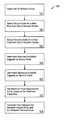
- FIG. 1shows a method of generating an interconnect fabric design problem according to an aspect of the present invention
- FIG. 2shows an exemplary set of network nodes for a design problem
- FIGS. 3-5show the set of network nodes of FIG. 2 in stages of progress as flows are added to a set of flow requirements for the design problem;
- FIG. 6shows an exemplary design problem that may be formed by the method of FIG. 1 ;
- FIG. 7shows an exemplary design solution for an interconnect fabric including switches and hubs
- FIG. 8shows a method for forming an interconnect fabric design problem having clusters and/or globally connected nodes in accordance with an aspect of the present invention
- FIG. 9shows an exemplary design problem that may be formed by the method of FIG. 8 .
- FIG. 10shows a system having a fabric design problem generation tool that may be used to generate an interconnect fabric design problem in accordance with an aspect of the present invention.
- FIG. 1shows a method 100 of generating an interconnect fabric design problem according to an aspect of the present invention.
- the design problemmay specify nodes that are to be interconnected by the design and requirements for communication flows among the specified nodes. These requirements may be referred to as flow requirements and may include, for example, source and terminal nodes for communication flows and required communication bandwidth for the flows.
- the method 100is performed generally by selecting a set of nodes and then adding flows to the requirements.
- a set of network nodes that are to be interconnected by the interconnect fabric design problemmay be determined.
- the set of network nodesmay, for example, be provided as a user-selected input to the method.
- FIG. 2shows an exemplary set of network nodes, including four source nodes (source nodes 10 - 16 in the figures below) and four terminal nodes (terminal nodes 20 - 26 in the figures below) for an interconnect design problem.
- Source nodesgenerally originate communications, whereas, terminal nodes are generally recipients of communications.
- a nodemay assume the role of source node with respect to some communications and of terminal node for other communications.
- the source nodes 10 - 16are host computers and terminal nodes 20 - 26 are storage devices.
- the interconnect fabric design problemmay be for storage area network.
- a source node for a new flow to be added to the flow requirementsmay be selected.
- the source nodemay be randomly selected from among the set of source nodes 10 - 16 .
- the source nodemay be selected from the set according to a predetermined sequence.
- the set of nodesmay include only one possible source node. In which case, that node is selected in the step 104 . It will be apparent that other techniques for selecting a source node from among the set of nodes may be utilized in the step 104 .
- the source node 10may be selected in step 104 .
- a terminal node for the new flow to be added to the flow requirementsmay be selected.
- selection of the terminal node in step 106may be performed randomly, according to a sequence, or in accordance with another selection technique.
- the terminal node 24may be selected in step 106 .
- the flow requirements for the design problemdo not exceed the capacities of the source and terminal nodes.
- each source and terminal nodemay have a specified maximum bandwidth capacity.
- each source and terminal nodemay have capacity for a maximum number of ports, each of which has a maximum bandwidth capacity. If the design problem specifies flow requirements that exceed a capacity of a source or terminal node, it becomes infeasible for an interconnect fabric to be designed that will meet such flow requirements without also modifying the source and terminal nodes or allowing flows to be split across multiple ports. For some network design problems, splitting of flows across multiple ports may be desired, particularly to test design techniques that can accommodate such flows.
- the present inventionpreferably avoids adding infeasible flows to the flow requirements by examining available capacities, taking into account existing flow requirements in the design problem and adding flows to the design problem that can be accommodated by the available capacities.
- a maximum available capacity at the source node selected in the step 102may be determined.
- the source node 10Since the source node 10 was selected the example of FIG. 2 , its maximum capacity may be determined in step 108 . Assume that the source node 10 has two ports, each having a maximum bandwidth capacity of 100 megabits per second (Mb/s). Thus, assuming there are no existing flows for the source node 10 in the design problem, the maximum bandwidth is 100 Mb/s. This also assumes flows are not split across the ports. If splitting is allowed, the maximum capacity would be 200 Mb/s.
- Mb/smegabits per second
- a maximum available capacity at the terminal node selected in the step 104may be determined. Since the terminal node 24 was selected in the example, its maximum capacity may be determined in step 110 . Assume that the terminal node 24 has three ports, each having a maximum bandwidth capacity of 100 Mb/s. Thus, assuming there are no existing flows for the terminal node 24 in the design problem, the maximum bandwidth capacity is also 100 Mb/s (or 300 Mb/s if splitting of flows is permitted).
- a maximum feasible bandwidth for the flow to be added between the selected source node and the terminal nodemay be set to the lower of the maximum capacities determined in the steps 108 and 110 . This is to avoid adding a flow that may exceed the maximum available capacity of either the source node or the terminal node.
- the maximum available capacity for the source node 10is 100 Mb/s and the maximum available capacity for the terminal node 24 is 100 Mb/s.
- the lower of the two capacitiesis also 100 Mb/s.
- the flowmay be generated between the selected source and terminal nodes.
- the bandwidth requirement for the flowmay be selected to be a value that is less than or equal to the maximum feasible value for flow, as determined in step 112 .
- the bandwidth requirementmay be randomly selected to be a value between 1 Mb/s and the maximum value.
- the flowmay be assigned to one of those ports either randomly or in accordance with a specified order. If splitting of flows is permitted, portions of the flow are assigned to ports while avoiding exceeding capacities of the ports.
- the bandwidth requirement for the flowmay be randomly selected in step 110 to be 10 Mb/s, which is less than the maximum value of 100 Mb/s.
- the requirements for this flowincluding its source and terminal nodes, port assignments and its bandwidth may then be added to the flow requirements for the design problem.
- FIG. 3illustrates the flow 60 after having been added to the flow requirements for the design problem. Because a port 30 at the source node 10 and each of three ports 34 , 36 and 38 at the terminal node 24 have sufficient capacity to accommodate the flow 60 , the flow 60 may be assigned the port 30 of the source node 10 and to a first port (i.e. the leftmost port in FIG. 3 ) of the terminal node 24 . Particularly, the flow 60 may be assigned to port 32 of the terminal node 24 .
- Additional flowsmay be added to the flow requirements for the design problem by repeating the steps 104 - 114 of the method 100 .
- FIG. 4illustrates the exemplary set of nodes from FIG. 1 after several passes of the method 100 . These include: the flow 60 between port 30 of source node 10 and port 32 of terminal node 24 ; a flow 62 between port 38 of source node 12 and port 48 of terminal node 20 ; a flow 64 between port 38 of source node 12 and port 50 of terminal node 22 ; a flow 66 between port 40 of source node 12 and port 34 of terminal node 24 ; a flow 68 between port 40 of source node 12 and port 52 of terminal node 26 ; a flow 70 between port 42 of source node 14 and port 34 of terminal node 24 ; a flow 72 between port 44 of source node 14 and port 36 of terminal node 24 ; and a flow 74 between port 46 of source node 16 and port 32 of terminal node 24 .
- the source node 12may be selected in the step 104 and the terminal node 24 may be selected in the step 106 .
- a new flow to be added to the flow requirements of FIG. 5may be between the source node 12 and the terminal node 24 .
- each of the ports 38 and 40 of the node 12has a maximum bandwidth capacity of 100 Mb/s; that flow 62 requires 40 Mb/s of capacity; and that each of the flows 64 , 66 and 68 requires 20 Mb/s.
- the available capacity at port 38may be determined to be 40 Mb/s (100 Mb/s minus 40 Mb/s for flow 62 and 20 Mb/s for flow 64 ) and the available capacity at port 40 may be determined to be 60 Mb/s (100 Mb/s minus 20 Mb/s for each of flows 66 and 68 ).
- the maximum available capacity at the source node 12may be determined in step 108 to be 60 Mb/s (at port 40 ).
- each of the ports 32 , 34 and 36 of terminal node 24has a maximum bandwidth capacity of 100 Mb/s.
- flow 60requires 10 Mb/s of capacity and flow 74 requires 30 Mb/s of capacity.
- the available capacity at port 32may be determined to be 60 Mb/s (100 Mb/s minus 10 Mb/s for flow 60 and 30 Mb/s for flow 74 ).
- flow 70requires 10 Mb/s of capacity.
- the available capacity at port 34may be determined to be 70 Mb/s (100 Mb/s minus 20 Mb/s for flow 66 and 10 Mb/s for flow 70 ).
- flow 72requires 80 Mb/s of capacity.
- the available capacity at port 36may be determined to be 20 Mb/s. Accordingly, the maximum available capacity at the terminal node 24 may be determined in step 110 to be 70 Mb/s (at port 34 ).
- the maximum requirement for the flow to be added between the source node 12 and terminal node 24may be set to lesser of these maximum values found in steps 108 and 110 .
- the available capacity of 60 Mb/s at the port 40is less than the available capacity of 70 Mb/s at the port 34 . Accordingly, the maximum requirement may be set to 60 Mb/s in the step 112 .
- the flowmay be generated between the source node 12 and the terminal node 24 .
- the bandwidth requirement for the flowmay be selected to be a value that at least 1 Mb/s and less than or equal to the maximum feasible value for flow of 60 Mb/s, as determined in step 112 .
- the bandwidth requirementmay be randomly selected to be 25 Mb/s. Because both ports 38 and 40 at the source node 12 may accommodate the flow, the flow may be assigned to the first port (i.e. the leftmost port), which in FIG. 4 is the port 38 . Similarly, because ports 32 and 34 at the terminal node 24 may accommodate the flow, the flow may be assigned to the first or leftmost port, which in FIG. 4 is the port 32 .
- FIG. 5shows the newly added flow 76 between the port 38 and the port 32 .
- the method 100 of FIG. 1may be repeated, adding flows to the interconnect fabric design problem until a stopping condition is reached.
- the stopping conditionmay include each source and terminal node having a specified number of flows.
- the stopping conditionmay include a random aspect, such as reaching a minimum number of flows or level of bandwidth required for the nodes and then adding a random number of additional flows or bandwidth levels to the design problem.
- the stopping conditionmay be based on ratio of a sum of bandwidth requirements assigned to a node to a sum of bandwidth capacity at the node. This ratio may also be referred to as “port saturation.”
- the design problemincludes a set of flow requirements that corresponds to the set of nodes.
- FIG. 6shows an exemplary design problem that includes a set of flow requirements 80 among the source nodes 10 - 16 and the terminal nodes 22 - 30 .
- FIG. 7illustrates an exemplary design in which interconnect devices 82 , 84 and 86 may be used to carry the flow requirements 80 for the design problem.
- a design techniquemay be applied to any number of design problems formed by the present invention.
- the present inventionfacilitates evaluation of interconnect fabric design techniques that may be under development or otherwise in need of evaluation.
- Particular examples of design techniquesare described in copending U.S. application Ser. No. 09/707,227, filed Nov. 16, 2000 and U.S. application Ser. No. 10/027,564, entitled, “Designing Interconnect Fabrics,” and filed Dec. 19, 2001, and which is continuation-in-part of U.S. application Ser. No. 09/707,227, the contents of both of which are hereby incorporated by reference. It will be apparent, however, that other uses may be made of a design problem formed by the present invention.
- an interconnect fabric design problemmay be formed having clusters of nodes.
- a cluster of nodesis a set of nodes which primarily or solely communicate with each other.
- an interconnect fabric design problemmay be formed having globally connected nodes.
- a globally-connected nodeis one that communicates with nodes of more that one cluster.
- FIG. 8shows a method 200 for forming an interconnect fabric design problem having clusters and/or globally connected nodes in accordance with an aspect of the present invention.
- step 202source and terminal nodes for an interconnect fabric design problem may be specified. Then, in step 204 , the source and terminal nodes may be grouped according to clusters. In addition, nodes that are to be globally-connected may be identified.
- FIG. 9shows an exemplary design problem that may be formed by the method of FIG. 8 .
- the set of nodes 10 - 16 , 20 - 26 of FIG. 6form a first cluster 250 of nodes in FIG. 9 .
- the set of flow requirements 80specify flow requirements among the nodes of the cluster 250 .
- a second cluster 252includes a set of nodes, including source nodes 256 - 260 and terminal nodes 262 - 266 .
- a set of flow requirements 268specify requirements for flows among the nodes of the cluster 252 .
- the example of FIG. 9also includes globally-connected nodes 270 and 272 .
- the globally-connected node 270may be a terminal node.
- a set of flow requirements 274may specify flow requirements between the globally-connected node 270 and the source nodes of the cluster 250
- a set of flow requirements 276may specify flow requirements between the globally-connected node 270 and the cluster 252 .
- the globally-connected node 272may be a source node.
- a set of flow requirements 278 between the globally-connected node 272may specify flow requirements between the terminal nodes of the cluster 250
- a set of flow requirements 280may specify flow requirements between globally-connected node 272 and the terminal nodes of the cluster 252 .
- a globally-connected nodemay act as both a source node and a terminal node and, thus, flow requirements may be provided between a globally-connected node and other nodes, including both source and terminal nodes.
- one of the clusters formed in step 204may be selected in order to form the flow requirements among the nodes of the cluster.
- the steps 104 - 114 of method 100may be utilized.
- pairs of a source node and a terminal nodemay be selected in steps 104 - 106 according to a sequence in which a first source node of the cluster is selected and, then, flows, if any, are formed between the selected source node and the terminal nodes of the cluster in accordance with steps 108 - 114 . Then, a next source node is selected in sequence and flows, if any, are formed between that source node and the terminal nodes of the cluster. Once all of the source nodes of the cluster have been selected and appropriate flows formed, then the terminal nodes of the cluster may be selected in sequence. While forming flows for terminal nodes, a sufficient number of flows for a terminal node may be found to have already been formed while forming flows for the source nodes. In which case, such a terminal node may be skipped.
- a first pass through the step 206may result in generation of the flow requirements 80 among the nodes of the cluster 250 , as explained above in reference to the method 100 of FIG. 1 .
- the flow requirements 268may be generated among the nodes of the cluster 252 , also by using the method 100 .
- the step 206may be repeated until flow requirements have been generated for each cluster of the design problem.
- flowsmay be generated for each globally-connected element.
- the method 100may be used in step 208 for generating these flows.
- the flow requirementsmay be specified to include flows between a globally-connected element and only some of the other source nodes and/or terminal nodes in the design problem.
- a terminal node for a flow to be addedmay be selected in step 106 .
- the terminal nodemay be a specified one of the existing nodes in the design problem or may be identified randomly from among the existing nodes.
- a source node for the flow to be addedmay be selected in step 104 .
- the design problemmay be specified to include at least one flow between a globally-connected element and each source node and/or each terminal node in the design problem.
- the flow requirements 274 and 276 for the globally-connected node 270may include a flow between the globally-connected node 270 and each of the source nodes 10 - 16 and 256 - 260 .
- the source nodes 10 - 16 and 256 - 260may be selected in step 208 according to a sequence until at least one flow has been formed between each source node 10 - 16 and 256 - 260 and the globally-connected element 270 .
- flow requirements 278 and 280may be generated for the globally-connected node 272 .
- the terminal nodes 20 - 26 and 262 - 266may be selected in step 208 according to a sequence until at least one flow has been formed between each terminal node 20 - 26 and 262 - 266 and the globally-connected element 272 .
- the step 208may be repeated for each globally-connected element in the design problem.
- additional flowsmay be added to the design problem.
- flowsmay be added to each cluster in a pseudo-random fashion.
- pseudo-randomwhat is meant is that computer-generated numbers may follow an apparently random pattern based on a seed value that controls a probability distribution of the generated numbers. For example, a minimum number of flows per node or per cluster may be specified and a maximum number of flows may be specified. Flows may be added such that the total randomly falls somewhere between the maximum and minimum numbers. Further, flows may be added between clusters. For example, a specified minimum and maximum number of source nodes in the design problem may have flows connected to a terminal node of another cluster.
- Flowsmay be added in step 210 so that the number of flows in the resulting design problem falls somewhere between the minimum and maximum numbers.
- a specified probability and random number generatormay be used to determine exactly how many flows are added. If the specified probability is low, then the number of flows in resulting design problem will be near the minimum, whereas, if the specified probability is high, then the number of flows in the resulting design problem will be near the maximum. Thus, the probability will generally control the density of flows (i.e. the number of flows per cluster).
- the possible range of numbers of flows in the resulting design problem that are added in step 210can be controlled by selecting the minimum and maximum numbers of flows. If there is wide difference, then the number of flows in the resulting design problem will be more variable, meaning that over a large number of repetitions of the method, the variability in the number of flows assigned would be higher. If there is narrow difference, then the number of flows in the resulting design problem will be less variable. In one embodiment, the minimum and maximum numbers may be set to the same level.
- a maximum number of additional flows that may be added to a clustermay be computed as a difference between a specified maximum number of flows for the cluster and the number of flows already in the cluster. More particularly, a maximum number of flows per source node (or per terminal node) in the cluster may be specified. This number may then be multiplied by the number of source nodes (or terminal nodes) in the cluster to determine the maximum number of flows for the cluster. Then, the number of existing flows in the cluster (as a result of adding flows in steps 206 and 208 ) may be subtracted from the product to determine the maximum number that may be added in step 210 .
- the method 100 of FIG. 1may be used to add flows to the cluster.
- a probability for keeping such additional flowsmay be specified.
- the flowmay be discarded in step 210 according to the probability. For example, assume that the maximum number of flows that may be added is three and the specified probability is seventy percent (70%). In which case, the method 100 is performed three times. For each flow formed by the method 100 , the specified probability of seventy percent is applied to the flow determine whether to keep or discard the flow (e.g., the probability of keeping any one of the flows is 70%). It will be apparent that other techniques may be utilized for adding additional flows to the design problem.
- FIG. 10shows a system having a fabric design problem generation tool 300 that may employ the method 100 (and the method 200 ) to generate a interconnect fabric design problem 302 .
- the fabric design problem generation tool 300may be implemented in computer software and/or hardware to perform its functions.
- Design information 304in one embodiment includes a list of hosts (source nodes) and devices (terminal nodes) 306 , a set of user-specified parameters 308 , and a set of device properties 310 .
- the design information 304may be implemented as an information store, such as a file or set of files or a database, etc.
- the list of hosts and devices 306may specify the source nodes and terminal nodes which are to be interconnected by flow requirements of the interconnect fabric design problem 302 . This list may also identify source and terminal nodes that are to be globally-connected. This list 306 may be specified by a user and may be obtained in step 102 of FIG. 1 and/or step 202 of FIG. 8 .
- the set of user-specified parameters 308may include, for example, a number of clusters to be formed (e.g., in step 204 of FIG. 8 ), a minimum number of flows for each cluster, each source node, each terminal node, and/or each globally-connected node (e.g., used in steps 206 , 208 and 210 of FIG. 8 ), a maximum number of flows for each cluster, each source node, each terminal node and/or each globally-connected node (e.g., used in step 210 of FIG. 8 ), and a probability that a particular flow will be retained or discarded (e.g., used in step 210 of FIG. 8 ).
- a number of clusters to be formede.g., in step 204 of FIG. 8
- a minimum number of flows for each clustere.g., each source node, each terminal node, and/or each globally-connected node
- a maximum number of flows for each clustere.g., used in step 210
- the user specified parameters 308may also specify a desired level of port saturation. For example, determining capacity available at a node, as in steps 108 or 110 , may depend on port saturation at the node and on unused capacity at each port of the node. Also, a user may specify a percentage of port capacities that may be used. In the examples above, the maximum bandwidth capacity of a port (e.g., port 38 of source node 12 ) was assumed to be 100 Mb/s. This capacity was then used to determine that maximum bandwidth of a flow that was feasible to add to the flow requirements. In this case, the percentage of port capacity that may be used may be assumed to be one hundred percent (100%). In other embodiments, a different percentage of port capacity may be specified for use. If the specified percentage was assumed to be 80%, in the example, then a flow would be feasible to add to the flow requirements only if the resulting flow requirements for that port remained less than or equal to 80 Mb/s.
- the user-specified parameters 308may further include a seed for a random number generator.
- the random number generatormay be implemented by the generation tool 300 to randomly select nodes between which a flow is to be added to the requirements (e.g., step 104 or 106 of FIG. 1 ), to determine whether to retain or discard additional flows (e.g., step 210 of FIG. 8 ), to select a bandwidth for a flow between upper and lower bounds (e.g., step 210 of FIG. 8 ), and so forth.
- the device properties data 310may specify, for example, a bandwidth capacity of each source node and terminal node, a number of ports for each and the bandwidth capacities of the ports.
- Design problem 302 generated by the interconnect problem generation tool 300may include the flow requirements generated in accordance with the present invention.
Landscapes
- Engineering & Computer Science (AREA)
- Computer Networks & Wireless Communication (AREA)
- Physics & Mathematics (AREA)
- Theoretical Computer Science (AREA)
- Signal Processing (AREA)
- General Physics & Mathematics (AREA)
- Geometry (AREA)
- Mathematical Analysis (AREA)
- Pure & Applied Mathematics (AREA)
- Computer Hardware Design (AREA)
- Evolutionary Computation (AREA)
- General Engineering & Computer Science (AREA)
- Mathematical Optimization (AREA)
- Computational Mathematics (AREA)
- Data Exchanges In Wide-Area Networks (AREA)
Abstract
Description
Claims (27)
Priority Applications (1)
| Application Number | Priority Date | Filing Date | Title |
|---|---|---|---|
| US10/066,051US9009004B2 (en) | 2002-01-31 | 2002-01-31 | Generating interconnect fabric requirements |
Applications Claiming Priority (1)
| Application Number | Priority Date | Filing Date | Title |
|---|---|---|---|
| US10/066,051US9009004B2 (en) | 2002-01-31 | 2002-01-31 | Generating interconnect fabric requirements |
Publications (2)
| Publication Number | Publication Date |
|---|---|
| US20030144822A1 US20030144822A1 (en) | 2003-07-31 |
| US9009004B2true US9009004B2 (en) | 2015-04-14 |
Family
ID=27610413
Family Applications (1)
| Application Number | Title | Priority Date | Filing Date |
|---|---|---|---|
| US10/066,051Active2032-03-26US9009004B2 (en) | 2002-01-31 | 2002-01-31 | Generating interconnect fabric requirements |
Country Status (1)
| Country | Link |
|---|---|
| US (1) | US9009004B2 (en) |
Families Citing this family (8)
| Publication number | Priority date | Publication date | Assignee | Title |
|---|---|---|---|---|
| US7000011B1 (en)* | 2000-11-06 | 2006-02-14 | Hewlett-Packard Development Company, Lp. | Designing interconnect fabrics |
| US20030145294A1 (en) | 2002-01-25 | 2003-07-31 | Ward Julie Ann | Verifying interconnect fabric designs |
| US20050265359A1 (en)* | 2004-05-13 | 2005-12-01 | Drew Julie W | Optimizing switch port assignments |
| EP3318009B1 (en) | 2015-06-30 | 2019-11-06 | British Telecommunications public limited company | Model management in a dynamic qos environment |
| US10965614B2 (en)* | 2015-06-30 | 2021-03-30 | British Telecommunications, Public Limited Company | Negotiating quality of service for data flows |
| US11616728B2 (en) | 2015-06-30 | 2023-03-28 | British Telecommunications Public Limited Company | Modifying quality of service treatment for data flows |
| US10699186B2 (en) | 2015-12-02 | 2020-06-30 | Google Llc | Determining orders of execution of a neural network |
| US11507487B2 (en)* | 2016-09-28 | 2022-11-22 | Vmware, Inc. | Control of a computing system to perform network fabric benchmark measurements |
Citations (83)
| Publication number | Priority date | Publication date | Assignee | Title |
|---|---|---|---|---|
| US4920487A (en) | 1988-12-12 | 1990-04-24 | The United States Of America As Represented By The Administrator Of The National Aeronautics And Space Administration | Method of up-front load balancing for local memory parallel processors |
| US5107489A (en) | 1989-10-30 | 1992-04-21 | Brown Paul J | Switch and its protocol for making dynamic connections |
| US5113496A (en) | 1987-08-04 | 1992-05-12 | Mccalley Karl W | Bus interconnection structure with redundancy linking plurality of groups of processors, with servers for each group mounted on chassis |
| US5138657A (en) | 1989-10-23 | 1992-08-11 | At&T Bell Laboratories | Method and apparatus for controlling a digital crossconnect system from a switching system |
| US5245609A (en) | 1991-01-30 | 1993-09-14 | International Business Machines Corporation | Communication network and a method of regulating the transmission of data packets in a communication network |
| US5307449A (en) | 1991-12-20 | 1994-04-26 | Apple Computer, Inc. | Method and apparatus for simultaneously rendering multiple scanlines |
| US5329619A (en) | 1992-10-30 | 1994-07-12 | Software Ag | Cooperative processing interface and communication broker for heterogeneous computing environments |
| US5426674A (en)* | 1990-02-06 | 1995-06-20 | Nemirovsky; Paul | Method and computer system for selecting and evaluating data routes and arranging a distributed data communication network |
| US5524212A (en) | 1992-04-27 | 1996-06-04 | University Of Washington | Multiprocessor system with write generate method for updating cache |
| WO1996017458A1 (en) | 1994-11-30 | 1996-06-06 | British Telecommunications Public Limited Company | Routing in a communication network |
| US5581689A (en) | 1993-12-28 | 1996-12-03 | Nec Corporation | Multi link type self healing system for communication networks |
| US5598532A (en) | 1993-10-21 | 1997-01-28 | Optimal Networks | Method and apparatus for optimizing computer networks |
| US5634011A (en) | 1992-06-18 | 1997-05-27 | International Business Machines Corporation | Distributed management communications network |
| US5634004A (en) | 1994-05-16 | 1997-05-27 | Network Programs, Inc. | Directly programmable distribution element |
| US5649105A (en) | 1992-11-10 | 1997-07-15 | Ibm Corp. | Collaborative working in a network |
| US5651005A (en) | 1995-08-29 | 1997-07-22 | Microsoft Corporation | System and methods for supplying continuous media data over an ATM public network |
| US5793362A (en) | 1995-12-04 | 1998-08-11 | Cabletron Systems, Inc. | Configurations tracking system using transition manager to evaluate votes to determine possible connections between ports in a communications network in accordance with transition tables |
| US5805578A (en) | 1995-10-27 | 1998-09-08 | International Business Machines Corporation | Automatic reconfiguration of multipoint communication channels |
| US5815402A (en) | 1996-06-07 | 1998-09-29 | Micron Technology, Inc. | System and method for changing the connected behavior of a circuit design schematic |
| US5831996A (en) | 1996-10-10 | 1998-11-03 | Lucent Technologies Inc. | Digital circuit test generator |
| US5835498A (en) | 1995-10-05 | 1998-11-10 | Silicon Image, Inc. | System and method for sending multiple data signals over a serial link |
| US5838919A (en) | 1996-09-10 | 1998-11-17 | Ganymede Software, Inc. | Methods, systems and computer program products for endpoint pair based communications network performance testing |
| US5857180A (en) | 1993-09-27 | 1999-01-05 | Oracle Corporation | Method and apparatus for implementing parallel operations in a database management system |
| US5878232A (en) | 1996-12-27 | 1999-03-02 | Compaq Computer Corporation | Dynamic reconfiguration of network device's virtual LANs using the root identifiers and root ports determined by a spanning tree procedure |
| US5970232A (en) | 1997-11-17 | 1999-10-19 | Cray Research, Inc. | Router table lookup mechanism |
| US5987517A (en) | 1996-03-27 | 1999-11-16 | Microsoft Corporation | System having a library of protocol independent reentrant network interface functions for providing common calling interface for communication and application protocols |
| US6003037A (en) | 1995-11-14 | 1999-12-14 | Progress Software Corporation | Smart objects for development of object oriented software |
| US6031984A (en) | 1998-03-09 | 2000-02-29 | I2 Technologies, Inc. | Method and apparatus for optimizing constraint models |
| US6038219A (en) | 1996-12-31 | 2000-03-14 | Paradyne Corporation | User-configurable frame relay network |
| US6047199A (en) | 1997-08-15 | 2000-04-04 | Bellsouth Intellectual Property Corporation | Systems and methods for transmitting mobile radio signals |
| US6052360A (en) | 1997-10-23 | 2000-04-18 | Mci Communications Corporation | Network restoration plan regeneration responsive to transitory conditions likely to affect network traffic |
| US6108782A (en) | 1996-12-13 | 2000-08-22 | 3Com Corporation | Distributed remote monitoring (dRMON) for networks |
| US6141355A (en) | 1998-11-06 | 2000-10-31 | Path 1 Network Technologies, Inc. | Time-synchronized multi-layer network switch for providing quality of service guarantees in computer networks |
| US6148000A (en) | 1996-10-02 | 2000-11-14 | International Business Machines Corporation | Merging of data cells at network nodes |
| US6157645A (en) | 1996-05-28 | 2000-12-05 | Kabushiki Kaisha Toshiba | ATM communication system and ATM communication method |
| US6195355B1 (en) | 1997-09-26 | 2001-02-27 | Sony Corporation | Packet-Transmission control method and packet-transmission control apparatus |
| US6209033B1 (en)* | 1995-02-01 | 2001-03-27 | Cabletron Systems, Inc. | Apparatus and method for network capacity evaluation and planning |
| US6212568B1 (en) | 1998-05-06 | 2001-04-03 | Creare Inc. | Ring buffered network bus data management system |
| US6253339B1 (en) | 1998-10-28 | 2001-06-26 | Telefonaktiebolaget Lm Ericsson (Publ) | Alarm correlation in a large communications network |
| US6331905B1 (en) | 1999-04-01 | 2001-12-18 | The Trustees Of Columbia University In The City Of New York | Network switch failure restoration |
| US6345048B1 (en) | 1998-04-30 | 2002-02-05 | Sbc Technology Resources, Inc. | ATM-based distributed virtual tandem switching system |
| US6363334B1 (en) | 1998-11-05 | 2002-03-26 | Lucent Technologies Inc. | Linear programming method of networking design for carrying traffic from endnodes to a core network at least cost |
| US20020083159A1 (en) | 2000-11-06 | 2002-06-27 | Ward Julie A. | Designing interconnect fabrics |
| US6418481B1 (en) | 1991-08-13 | 2002-07-09 | Storage Technology Corporation | Reconfigurable matrix switch for managing the physical layer of local area network |
| US6442584B1 (en) | 1997-05-16 | 2002-08-27 | Sybase, Inc. | Methods for resource consolidation in a computing environment |
| US20020120770A1 (en) | 2001-02-28 | 2002-08-29 | Parham Jeffrey B. | Method for designating communication paths in a network |
| US6452924B1 (en) | 1997-11-10 | 2002-09-17 | Enron Warpspeed Services, Inc. | Method and apparatus for controlling bandwidth in a switched broadband multipoint/multimedia network |
| US20020156828A1 (en) | 2001-04-24 | 2002-10-24 | Takeshi Ishizaki | Integrated service management system |
| US20020188732A1 (en) | 2001-06-06 | 2002-12-12 | Buckman Charles R. | System and method for allocating bandwidth across a network |
| US6526420B2 (en) | 1998-11-20 | 2003-02-25 | Hewlett-Packard Company | Non-linear constraint optimization in storage system configuration |
| US6539531B2 (en) | 1999-02-25 | 2003-03-25 | Formfactor, Inc. | Method of designing, fabricating, testing and interconnecting an IC to external circuit nodes |
| US6539027B1 (en) | 1999-01-19 | 2003-03-25 | Coastcom | Reconfigurable, intelligent signal multiplexer and network design and maintenance system therefor |
| US20030065758A1 (en) | 2001-09-28 | 2003-04-03 | O'sullivan Michael Justin | Module-building method for designing interconnect fabrics |
| US6557169B1 (en) | 1998-10-11 | 2003-04-29 | International Business Machines Corporation | Method and system for changing the operating system of a workstation connected to a data transmission network |
| US6570850B1 (en) | 1998-04-23 | 2003-05-27 | Giganet, Inc. | System and method for regulating message flow in a digital data network |
| US6594701B1 (en) | 1998-08-04 | 2003-07-15 | Microsoft Corporation | Credit-based methods and systems for controlling data flow between a sender and a receiver with reduced copying of data |
| US6598080B1 (en) | 1994-08-31 | 2003-07-22 | Kabushiki Kaisha Toshiba | Network interconnection apparatus network node apparatus and packet transfer method for high speed large capacity inter-network communication |
| US20030145294A1 (en) | 2002-01-25 | 2003-07-31 | Ward Julie Ann | Verifying interconnect fabric designs |
| US6603769B1 (en) | 1998-05-28 | 2003-08-05 | Cisco Technology, Inc. | Method and system for improving traffic operation in an internet environment |
| US6611872B1 (en) | 1999-01-11 | 2003-08-26 | Fastforward Networks, Inc. | Performing multicast communication in computer networks by using overlay routing |
| US6614796B1 (en) | 1997-01-23 | 2003-09-02 | Gadzoox Networks, Inc, | Fibre channel arbitrated loop bufferless switch circuitry to increase bandwidth without significant increase in cost |
| US6625777B1 (en) | 1999-10-19 | 2003-09-23 | Motorola, Inc. | Method of identifying an improved configuration for a communication system using coding gain and an apparatus therefor |
| US6628649B1 (en) | 1999-10-29 | 2003-09-30 | Cisco Technology, Inc. | Apparatus and methods providing redundant routing in a switched network device |
| US6633909B1 (en) | 1999-09-23 | 2003-10-14 | International Business Machines Corporation | Notification method that guarantees a system manager discovers an SNMP agent |
| US6650639B2 (en) | 1996-09-27 | 2003-11-18 | Enterasys Networks, Inc. | Secure fast packet switch having improved memory utilization |
| US6668308B2 (en) | 2000-06-10 | 2003-12-23 | Hewlett-Packard Development Company, L.P. | Scalable architecture based on single-chip multiprocessing |
| US6675328B1 (en) | 1999-10-08 | 2004-01-06 | Vigilant Networks, Llc | System and method to determine data throughput in a communication network |
| US6687222B1 (en) | 1999-07-02 | 2004-02-03 | Cisco Technology, Inc. | Backup service managers for providing reliable network services in a distributed environment |
| US6694361B1 (en) | 2000-06-30 | 2004-02-17 | Intel Corporation | Assigning multiple LIDs to ports in a cluster |
| US6697369B1 (en) | 1999-09-28 | 2004-02-24 | Lucent Technologies Inc | Admission control adjustment in data networks using maximum cell count |
| US6697334B1 (en) | 2000-01-18 | 2004-02-24 | At&T Corp. | Method for designing a network |
| US6697854B1 (en) | 1999-02-22 | 2004-02-24 | International Business Machines Corporation | Method and apparatus for providing configuration information using a SIGA vector and utilizing a queued direct input-output device |
| US6701327B1 (en) | 1999-05-11 | 2004-03-02 | 3Com Corporation | Merging network data sets comprising data acquired by interrogation of a network |
| US6724757B1 (en) | 1999-01-15 | 2004-04-20 | Cisco Technology, Inc. | Configurable network router |
| US6744767B1 (en) | 1999-12-30 | 2004-06-01 | At&T Corp. | Method and apparatus for provisioning and monitoring internet protocol quality of service |
| US6757731B1 (en) | 1999-02-25 | 2004-06-29 | Nortel Networks Limited | Apparatus and method for interfacing multiple protocol stacks in a communication network |
| US6766381B1 (en) | 1999-08-27 | 2004-07-20 | International Business Machines Corporation | VLSI network processor and methods |
| US6778496B1 (en) | 2000-06-07 | 2004-08-17 | Lucent Technologies Inc. | Distributed call admission and load balancing method and apparatus for packet networks |
| US6804245B2 (en) | 2001-08-17 | 2004-10-12 | Mcdata Corporation | Compact, shared route lookup table for a fiber channel switch |
| US20050021831A1 (en) | 2003-07-25 | 2005-01-27 | Artur Andrzejak | Determining placement of distributed application onto distributed resource infrastructure |
| US20050021583A1 (en) | 2003-07-25 | 2005-01-27 | Artur Andrzejak | Determination of one or more variables to receive value changes in local search solution of integer programming problem |
| US20050033844A1 (en) | 2003-07-25 | 2005-02-10 | Artur Andrzejak | Incorporating constraints and preferences for determining placement of distributed application onto distributed resource infrastructure |
| US6857027B1 (en) | 2000-11-14 | 2005-02-15 | 3Com Corporation | Intelligent network topology and configuration verification using a method of loop detection |
- 2002
- 2002-01-31USUS10/066,051patent/US9009004B2/enactiveActive
Patent Citations (85)
| Publication number | Priority date | Publication date | Assignee | Title |
|---|---|---|---|---|
| US5113496A (en) | 1987-08-04 | 1992-05-12 | Mccalley Karl W | Bus interconnection structure with redundancy linking plurality of groups of processors, with servers for each group mounted on chassis |
| US4920487A (en) | 1988-12-12 | 1990-04-24 | The United States Of America As Represented By The Administrator Of The National Aeronautics And Space Administration | Method of up-front load balancing for local memory parallel processors |
| US5138657A (en) | 1989-10-23 | 1992-08-11 | At&T Bell Laboratories | Method and apparatus for controlling a digital crossconnect system from a switching system |
| US5107489A (en) | 1989-10-30 | 1992-04-21 | Brown Paul J | Switch and its protocol for making dynamic connections |
| US5426674A (en)* | 1990-02-06 | 1995-06-20 | Nemirovsky; Paul | Method and computer system for selecting and evaluating data routes and arranging a distributed data communication network |
| US5245609A (en) | 1991-01-30 | 1993-09-14 | International Business Machines Corporation | Communication network and a method of regulating the transmission of data packets in a communication network |
| US6418481B1 (en) | 1991-08-13 | 2002-07-09 | Storage Technology Corporation | Reconfigurable matrix switch for managing the physical layer of local area network |
| US5307449A (en) | 1991-12-20 | 1994-04-26 | Apple Computer, Inc. | Method and apparatus for simultaneously rendering multiple scanlines |
| US5524212A (en) | 1992-04-27 | 1996-06-04 | University Of Washington | Multiprocessor system with write generate method for updating cache |
| US5634011A (en) | 1992-06-18 | 1997-05-27 | International Business Machines Corporation | Distributed management communications network |
| US5329619A (en) | 1992-10-30 | 1994-07-12 | Software Ag | Cooperative processing interface and communication broker for heterogeneous computing environments |
| US5649105A (en) | 1992-11-10 | 1997-07-15 | Ibm Corp. | Collaborative working in a network |
| US5857180A (en) | 1993-09-27 | 1999-01-05 | Oracle Corporation | Method and apparatus for implementing parallel operations in a database management system |
| US5598532A (en) | 1993-10-21 | 1997-01-28 | Optimal Networks | Method and apparatus for optimizing computer networks |
| US5581689A (en) | 1993-12-28 | 1996-12-03 | Nec Corporation | Multi link type self healing system for communication networks |
| US5634004A (en) | 1994-05-16 | 1997-05-27 | Network Programs, Inc. | Directly programmable distribution element |
| US6598080B1 (en) | 1994-08-31 | 2003-07-22 | Kabushiki Kaisha Toshiba | Network interconnection apparatus network node apparatus and packet transfer method for high speed large capacity inter-network communication |
| WO1996017458A1 (en) | 1994-11-30 | 1996-06-06 | British Telecommunications Public Limited Company | Routing in a communication network |
| US6209033B1 (en)* | 1995-02-01 | 2001-03-27 | Cabletron Systems, Inc. | Apparatus and method for network capacity evaluation and planning |
| US5651005A (en) | 1995-08-29 | 1997-07-22 | Microsoft Corporation | System and methods for supplying continuous media data over an ATM public network |
| US5835498A (en) | 1995-10-05 | 1998-11-10 | Silicon Image, Inc. | System and method for sending multiple data signals over a serial link |
| US5805578A (en) | 1995-10-27 | 1998-09-08 | International Business Machines Corporation | Automatic reconfiguration of multipoint communication channels |
| US6003037A (en) | 1995-11-14 | 1999-12-14 | Progress Software Corporation | Smart objects for development of object oriented software |
| US5793362A (en) | 1995-12-04 | 1998-08-11 | Cabletron Systems, Inc. | Configurations tracking system using transition manager to evaluate votes to determine possible connections between ports in a communications network in accordance with transition tables |
| US5987517A (en) | 1996-03-27 | 1999-11-16 | Microsoft Corporation | System having a library of protocol independent reentrant network interface functions for providing common calling interface for communication and application protocols |
| US6157645A (en) | 1996-05-28 | 2000-12-05 | Kabushiki Kaisha Toshiba | ATM communication system and ATM communication method |
| US5815402A (en) | 1996-06-07 | 1998-09-29 | Micron Technology, Inc. | System and method for changing the connected behavior of a circuit design schematic |
| US5838919A (en) | 1996-09-10 | 1998-11-17 | Ganymede Software, Inc. | Methods, systems and computer program products for endpoint pair based communications network performance testing |
| US6650639B2 (en) | 1996-09-27 | 2003-11-18 | Enterasys Networks, Inc. | Secure fast packet switch having improved memory utilization |
| US6148000A (en) | 1996-10-02 | 2000-11-14 | International Business Machines Corporation | Merging of data cells at network nodes |
| US5831996A (en) | 1996-10-10 | 1998-11-03 | Lucent Technologies Inc. | Digital circuit test generator |
| US6108782A (en) | 1996-12-13 | 2000-08-22 | 3Com Corporation | Distributed remote monitoring (dRMON) for networks |
| US5878232A (en) | 1996-12-27 | 1999-03-02 | Compaq Computer Corporation | Dynamic reconfiguration of network device's virtual LANs using the root identifiers and root ports determined by a spanning tree procedure |
| US6038219A (en) | 1996-12-31 | 2000-03-14 | Paradyne Corporation | User-configurable frame relay network |
| US6614796B1 (en) | 1997-01-23 | 2003-09-02 | Gadzoox Networks, Inc, | Fibre channel arbitrated loop bufferless switch circuitry to increase bandwidth without significant increase in cost |
| US6442584B1 (en) | 1997-05-16 | 2002-08-27 | Sybase, Inc. | Methods for resource consolidation in a computing environment |
| US6047199A (en) | 1997-08-15 | 2000-04-04 | Bellsouth Intellectual Property Corporation | Systems and methods for transmitting mobile radio signals |
| US6195355B1 (en) | 1997-09-26 | 2001-02-27 | Sony Corporation | Packet-Transmission control method and packet-transmission control apparatus |
| US6052360A (en) | 1997-10-23 | 2000-04-18 | Mci Communications Corporation | Network restoration plan regeneration responsive to transitory conditions likely to affect network traffic |
| US6452924B1 (en) | 1997-11-10 | 2002-09-17 | Enron Warpspeed Services, Inc. | Method and apparatus for controlling bandwidth in a switched broadband multipoint/multimedia network |
| US5970232A (en) | 1997-11-17 | 1999-10-19 | Cray Research, Inc. | Router table lookup mechanism |
| US6031984A (en) | 1998-03-09 | 2000-02-29 | I2 Technologies, Inc. | Method and apparatus for optimizing constraint models |
| US6570850B1 (en) | 1998-04-23 | 2003-05-27 | Giganet, Inc. | System and method for regulating message flow in a digital data network |
| US6345048B1 (en) | 1998-04-30 | 2002-02-05 | Sbc Technology Resources, Inc. | ATM-based distributed virtual tandem switching system |
| US6212568B1 (en) | 1998-05-06 | 2001-04-03 | Creare Inc. | Ring buffered network bus data management system |
| US6603769B1 (en) | 1998-05-28 | 2003-08-05 | Cisco Technology, Inc. | Method and system for improving traffic operation in an internet environment |
| US6594701B1 (en) | 1998-08-04 | 2003-07-15 | Microsoft Corporation | Credit-based methods and systems for controlling data flow between a sender and a receiver with reduced copying of data |
| US6557169B1 (en) | 1998-10-11 | 2003-04-29 | International Business Machines Corporation | Method and system for changing the operating system of a workstation connected to a data transmission network |
| US6253339B1 (en) | 1998-10-28 | 2001-06-26 | Telefonaktiebolaget Lm Ericsson (Publ) | Alarm correlation in a large communications network |
| US6363334B1 (en) | 1998-11-05 | 2002-03-26 | Lucent Technologies Inc. | Linear programming method of networking design for carrying traffic from endnodes to a core network at least cost |
| US6141355A (en) | 1998-11-06 | 2000-10-31 | Path 1 Network Technologies, Inc. | Time-synchronized multi-layer network switch for providing quality of service guarantees in computer networks |
| US6526420B2 (en) | 1998-11-20 | 2003-02-25 | Hewlett-Packard Company | Non-linear constraint optimization in storage system configuration |
| US6611872B1 (en) | 1999-01-11 | 2003-08-26 | Fastforward Networks, Inc. | Performing multicast communication in computer networks by using overlay routing |
| US6724757B1 (en) | 1999-01-15 | 2004-04-20 | Cisco Technology, Inc. | Configurable network router |
| US6539027B1 (en) | 1999-01-19 | 2003-03-25 | Coastcom | Reconfigurable, intelligent signal multiplexer and network design and maintenance system therefor |
| US6697854B1 (en) | 1999-02-22 | 2004-02-24 | International Business Machines Corporation | Method and apparatus for providing configuration information using a SIGA vector and utilizing a queued direct input-output device |
| US6539531B2 (en) | 1999-02-25 | 2003-03-25 | Formfactor, Inc. | Method of designing, fabricating, testing and interconnecting an IC to external circuit nodes |
| US6757731B1 (en) | 1999-02-25 | 2004-06-29 | Nortel Networks Limited | Apparatus and method for interfacing multiple protocol stacks in a communication network |
| US6331905B1 (en) | 1999-04-01 | 2001-12-18 | The Trustees Of Columbia University In The City Of New York | Network switch failure restoration |
| US6701327B1 (en) | 1999-05-11 | 2004-03-02 | 3Com Corporation | Merging network data sets comprising data acquired by interrogation of a network |
| US6687222B1 (en) | 1999-07-02 | 2004-02-03 | Cisco Technology, Inc. | Backup service managers for providing reliable network services in a distributed environment |
| US6766381B1 (en) | 1999-08-27 | 2004-07-20 | International Business Machines Corporation | VLSI network processor and methods |
| US6633909B1 (en) | 1999-09-23 | 2003-10-14 | International Business Machines Corporation | Notification method that guarantees a system manager discovers an SNMP agent |
| US6697369B1 (en) | 1999-09-28 | 2004-02-24 | Lucent Technologies Inc | Admission control adjustment in data networks using maximum cell count |
| US6675328B1 (en) | 1999-10-08 | 2004-01-06 | Vigilant Networks, Llc | System and method to determine data throughput in a communication network |
| US6625777B1 (en) | 1999-10-19 | 2003-09-23 | Motorola, Inc. | Method of identifying an improved configuration for a communication system using coding gain and an apparatus therefor |
| US6628649B1 (en) | 1999-10-29 | 2003-09-30 | Cisco Technology, Inc. | Apparatus and methods providing redundant routing in a switched network device |
| US6744767B1 (en) | 1999-12-30 | 2004-06-01 | At&T Corp. | Method and apparatus for provisioning and monitoring internet protocol quality of service |
| US6697334B1 (en) | 2000-01-18 | 2004-02-24 | At&T Corp. | Method for designing a network |
| US6778496B1 (en) | 2000-06-07 | 2004-08-17 | Lucent Technologies Inc. | Distributed call admission and load balancing method and apparatus for packet networks |
| US6668308B2 (en) | 2000-06-10 | 2003-12-23 | Hewlett-Packard Development Company, L.P. | Scalable architecture based on single-chip multiprocessing |
| US6694361B1 (en) | 2000-06-30 | 2004-02-17 | Intel Corporation | Assigning multiple LIDs to ports in a cluster |
| US20020091804A1 (en) | 2000-11-06 | 2002-07-11 | Ward Julie Ann | Reliability for interconnect fabrics |
| US20020083159A1 (en) | 2000-11-06 | 2002-06-27 | Ward Julie A. | Designing interconnect fabrics |
| US20020091845A1 (en) | 2000-11-06 | 2002-07-11 | Ward Julie Ann | Reliability for interconnect fabrics |
| US6857027B1 (en) | 2000-11-14 | 2005-02-15 | 3Com Corporation | Intelligent network topology and configuration verification using a method of loop detection |
| US20020120770A1 (en) | 2001-02-28 | 2002-08-29 | Parham Jeffrey B. | Method for designating communication paths in a network |
| US20020156828A1 (en) | 2001-04-24 | 2002-10-24 | Takeshi Ishizaki | Integrated service management system |
| US20020188732A1 (en) | 2001-06-06 | 2002-12-12 | Buckman Charles R. | System and method for allocating bandwidth across a network |
| US6804245B2 (en) | 2001-08-17 | 2004-10-12 | Mcdata Corporation | Compact, shared route lookup table for a fiber channel switch |
| US20030065758A1 (en) | 2001-09-28 | 2003-04-03 | O'sullivan Michael Justin | Module-building method for designing interconnect fabrics |
| US20030145294A1 (en) | 2002-01-25 | 2003-07-31 | Ward Julie Ann | Verifying interconnect fabric designs |
| US20050021831A1 (en) | 2003-07-25 | 2005-01-27 | Artur Andrzejak | Determining placement of distributed application onto distributed resource infrastructure |
| US20050021583A1 (en) | 2003-07-25 | 2005-01-27 | Artur Andrzejak | Determination of one or more variables to receive value changes in local search solution of integer programming problem |
| US20050033844A1 (en) | 2003-07-25 | 2005-02-10 | Artur Andrzejak | Incorporating constraints and preferences for determining placement of distributed application onto distributed resource infrastructure |
Non-Patent Citations (34)
| Title |
|---|
| A. Richard Newton, Interface-Based Design; Introduction, University of California at Berkeley, Apr. 1999. |
| Andre Dehon, Notes on Coupling Processors with Reconfigurable Logic, MIT Transit Project, Transit Note #118, 1995. |
| Anil Kamath et al. "Routing and Admission Control in General Topology Network with Poisson Arrivals". Society for Industrial and Applied Mathematics, 1996. pp. 269-278.* |
| Bertsekas, Dimitri P. "Linear Network Optimization," The MIT Press, Cambridge/London, 1991, Appendix A.1.1, pp. 253-260. |
| Cathy Fulton et al., Impact Analysis of Packet-Level Scheduling on an ATM Shared-Memory Switch, Infocom, vol. 3 pp. 947-954, 1998, IEEE, New York, NY. |
| Christodoulos A. Floudas et al., Quadratic Optimization, 1995. |
| Derek C. W. Pao, A Congestion Control Algorithm for Multipoint-to-Multipoint ABR Service in ATM Network, Proceedings of the IEEE Conference on High Performance Switching and Routing, pp. 167-175, Jun. 26, 2000, IEEE Press, New York, NY. |
| Hiroshi Inose, An Introduction to Digital Integrated Communication Systems, pp. 87-89, 1979, Peter Peregrinus Ltd., Stevenage, United Kingdom. |
| I. Widjaja et al., Performance Issues in VC-Merge Capable ATM LSRs, RFC 2682, Sep. 1999, The Internet Society, Reston, VA. |
| Joachim P. Walser, Solving Linear Pseudo-Boolean Constraint Problems with Local Search, 1997, American Association for Artificial Intelligence, Menlo Park, CA. |
| Julie Ward Drew et al., U.S. Appl. No. 10/290,760, filed Nov. 8, 2002. |
| Julie Ward Drew et al., U.S. Appl. No. 10/845,855, filed May 13, 2004. |
| Julie Ward Drew, U.S. Appl. No. 10/290,643, filed Nov. 8, 2002. |
| Julie Ward et al., Appia: Automatic Storage Area Network Fabric Design, Conference on File and Storage Technologies (FAST'02), pp. 203-217, Jan. 28, 2002, Usenix, Berkeley, CA. |
| Julie Ward et al., Storage Area Network (SAN) Fabric Design, PowerPoint presentation given at Berkeley, IEOR Department Seminar, Berkeley CA, Oct. 8, 2001. |
| Julie Ward et al., Storage Area Network (SAN) Fabric Design, PowerPoint presentation given at the INFORMS International Conference, Maui HI, Jun. 19, 2001. |
| Julie Ward et al., Storage Area Network Fabric Design, PowerPoint presentation given at the Math Sciences Research Institute for Combinatorial Design, Berkeley CA, Nov. 8, 2000. |
| Julie Ward, U.S. Appl. No. 09/707,227, filed Nov. 6, 2000. |
| Klingman, et al. "NETGEN: A program for generating largescale capacitated assignment, transporation, and minimum cost flow network problems," Mangement Science, p. 814-821(1974). |
| Mathew Andrews et al., Integrated Scheduling of Unicast and Multicast Traffic in an Input-Queued Switch, 1999. . |
| Mathew Andrews et al., Integrated Scheduling of Unicast and Multicast Traffic in an Input-Queued Switch, 1999. <http://cm.bell-labs.com/cm/ms/who/andrews/infocom99switch.ps>. |
| Matthew T. O'Keefe et al., Designing Fibre Channel Storage Area Networks, Feb. 2001. . |
| Matthew T. O'Keefe et al., Designing Fibre Channel Storage Area Networks, Feb. 2001. <http://www.borg.umn.edu/fc/papers/SANTK.pdf>. |
| Oryal Tanir et al., Structural Reuse in the Design of ATM Switch Fabrics, 1997. |
| Parameswaran Ramanathan et al., Resource Placement with Multiple Adjacency Constraints in k-ary n-Cubes, 1995. |
| Rainer Schoenen et al., Weighted Arbitration Algorithms with Priorities for Input-Queued Switches with 100% Thoughput, 1999, . |
| Rainer Schoenen et al., Weighted Arbitration Algorithms with Priorities for Input-Queued Switches with 100% Thoughput, 1999, <http://www.iss.rwth-aachen.de/Projekte/Theo/papers/Schoenen99bssw.ps.gz>. |
| Ravindra K. Ahuja et al., Network Flows: Theory, Algorithms, and Applications, pp. 4-9, 649-686, 1993, Prentice-Hall, Upper Saddle River, NJ. |
| Robert E. Bixby, Solving Real-World Linear Programs: A Decade and More of Progress, Jan. 2002. |
| Shahoumian et al. "Storage Area Network Fabric Design". Nov. 8, 2000. pp. 1-8.* |
| Staffan Bo Strand, Storage Area Networks and SANTK, Thesis, Dec. 2001, University of Minnesota, Minneapolis, MN. |
| Staffan Strand, Automatic Generation of Core/Edge Topology SANs Using SANTK, May 23, 2002. |
| Viraphol Chaiyakul, Assignment Decision Diagram for High-Level Synthesis, 1992. |
| Zbigniew Dziong, Marek Juda, Lorne Mason; A Framework for Bandwidth Management in ATM Networks-Aggregate Equivalent Bandwidth Estimation Approach; IEEE?ACM Transactions on Networking, 1997; IEEE Press; vol. 5 Issue 1 pp. 134-147.* |
Also Published As
| Publication number | Publication date |
|---|---|
| US20030144822A1 (en) | 2003-07-31 |
Similar Documents
| Publication | Publication Date | Title |
|---|---|---|
| US7076537B2 (en) | Designing interconnect fabrics | |
| Awerbuch et al. | Competitive Non-Preemptive Call Control. | |
| Kleinberg | Single-source unsplittable flow | |
| TW412695B (en) | Method and apparatus for allocating processing resources | |
| US20100268799A1 (en) | Methods of Structuring Data, Pre-Compiled Exception List Engines, and Network Appliances | |
| US20030142627A1 (en) | Method of optimizing network capacity and fault tolerance in deadlock-free routing | |
| JPH0241054A (en) | How to select the lowest weight route in a communication network | |
| US9009004B2 (en) | Generating interconnect fabric requirements | |
| US7308494B1 (en) | Reprovisioning technique for an interconnect fabric design | |
| Feng et al. | Bound-based network tomography with additive metrics | |
| Kim et al. | Channel assignment in cellular radio using genetic algorithms | |
| WO1999046874A1 (en) | Summarization of routing information in a hierarchical network | |
| Vukadinović et al. | A spectral analysis of the Internet topology | |
| Kennington et al. | The path restoration version of the spare capacity allocation problem with modularity restrictions: Models, algorithms, and an empirical analysis | |
| Awerbuch et al. | On-line competitive algorithms for call admission in optical networks | |
| US6816487B1 (en) | Mapping of high bandwidth connections in a multi-stage switch | |
| Di Lena et al. | A right placement makes a happy emulator: a placement module for distributed sdn/nfv emulation | |
| EP3902212B1 (en) | A method to mitigate hash correlation in multi-path networks | |
| Riedl | A versatile genetic algorithm for network planning | |
| CN118250215A (en) | Method and equipment for planning paths between logic blocks of network topology structure | |
| CN118075198A (en) | Method and equipment for planning path of high-speed network topology structure | |
| CN109300032B (en) | Block generation method, device, equipment and computer readable storage medium | |
| Zhang et al. | Logarithmically scalable routing algorithms in large optical networks | |
| Fischer et al. | Solving the routing and wavelength assignment problem with a multilevel distributed memetic algorithm | |
| Bentall et al. | Benchmarking the restoration of heavily loaded networks using a two dimensional order-based genetic algorithm |
Legal Events
| Date | Code | Title | Description |
|---|---|---|---|
| AS | Assignment | Owner name:HEWLETT-PACKARD COMPANY, COLORADO Free format text:ASSIGNMENT OF ASSIGNORS INTEREST;ASSIGNORS:PEH, LI-SHIUAN;O'SULLIVAN, MICHAEL JUSTIN;WILKES, JOHN;AND OTHERS;REEL/FRAME:012944/0029;SIGNING DATES FROM 20020128 TO 20020130 Owner name:HEWLETT-PACKARD COMPANY, COLORADO Free format text:ASSIGNMENT OF ASSIGNORS INTEREST;ASSIGNORS:PEH, LI-SHIUAN;O'SULLIVAN, MICHAEL JUSTIN;WILKES, JOHN;AND OTHERS;SIGNING DATES FROM 20020128 TO 20020130;REEL/FRAME:012944/0029 | |
| AS | Assignment | Owner name:HEWLETT-PACKARD DEVELOPMENT COMPANY L.P., TEXAS Free format text:ASSIGNMENT OF ASSIGNORS INTEREST;ASSIGNOR:HEWLETT-PACKARD COMPANY;REEL/FRAME:014061/0492 Effective date:20030926 Owner name:HEWLETT-PACKARD DEVELOPMENT COMPANY L.P.,TEXAS Free format text:ASSIGNMENT OF ASSIGNORS INTEREST;ASSIGNOR:HEWLETT-PACKARD COMPANY;REEL/FRAME:014061/0492 Effective date:20030926 | |
| STCF | Information on status: patent grant | Free format text:PATENTED CASE | |
| AS | Assignment | Owner name:HEWLETT PACKARD ENTERPRISE DEVELOPMENT LP, TEXAS Free format text:ASSIGNMENT OF ASSIGNORS INTEREST;ASSIGNOR:HEWLETT-PACKARD DEVELOPMENT COMPANY, L.P.;REEL/FRAME:037079/0001 Effective date:20151027 | |
| MAFP | Maintenance fee payment | Free format text:PAYMENT OF MAINTENANCE FEE, 4TH YEAR, LARGE ENTITY (ORIGINAL EVENT CODE: M1551); ENTITY STATUS OF PATENT OWNER: LARGE ENTITY Year of fee payment:4 | |
| MAFP | Maintenance fee payment | Free format text:PAYMENT OF MAINTENANCE FEE, 8TH YEAR, LARGE ENTITY (ORIGINAL EVENT CODE: M1552); ENTITY STATUS OF PATENT OWNER: LARGE ENTITY Year of fee payment:8 |