US9007744B2 - Media appliance and method for use of same - Google Patents
Media appliance and method for use of sameDownload PDFInfo
- Publication number
- US9007744B2 US9007744B2US14/306,000US201414306000AUS9007744B2US 9007744 B2US9007744 B2US 9007744B2US 201414306000 AUS201414306000 AUS 201414306000AUS 9007744 B2US9007744 B2US 9007744B2
- Authority
- US
- United States
- Prior art keywords
- port
- ports
- panel
- housing
- optio
- Prior art date
- Legal status (The legal status is an assumption and is not a legal conclusion. Google has not performed a legal analysis and makes no representation as to the accuracy of the status listed.)
- Active
Links
Images


Classifications
- H—ELECTRICITY
- H02—GENERATION; CONVERSION OR DISTRIBUTION OF ELECTRIC POWER
- H02B—BOARDS, SUBSTATIONS OR SWITCHING ARRANGEMENTS FOR THE SUPPLY OR DISTRIBUTION OF ELECTRIC POWER
- H02B1/00—Frameworks, boards, panels, desks, casings; Details of substations or switching arrangements
- H02B1/26—Casings; Parts thereof or accessories therefor
- H02B1/40—Wall-mounted casings; Parts thereof or accessories therefor
- H02B1/42—Mounting of devices therein
- H—ELECTRICITY
- H02—GENERATION; CONVERSION OR DISTRIBUTION OF ELECTRIC POWER
- H02B—BOARDS, SUBSTATIONS OR SWITCHING ARRANGEMENTS FOR THE SUPPLY OR DISTRIBUTION OF ELECTRIC POWER
- H02B1/00—Frameworks, boards, panels, desks, casings; Details of substations or switching arrangements
- H02B1/56—Cooling; Ventilation
- H—ELECTRICITY
- H02—GENERATION; CONVERSION OR DISTRIBUTION OF ELECTRIC POWER
- H02G—INSTALLATION OF ELECTRIC CABLES OR LINES, OR OF COMBINED OPTICAL AND ELECTRIC CABLES OR LINES
- H02G3/00—Installations of electric cables or lines or protective tubing therefor in or on buildings, equivalent structures or vehicles
- H02G3/02—Details
- H02G3/08—Distribution boxes; Connection or junction boxes
- H02G3/10—Distribution boxes; Connection or junction boxes for surface mounting on a wall
- H—ELECTRICITY
- H04—ELECTRIC COMMUNICATION TECHNIQUE
- H04N—PICTORIAL COMMUNICATION, e.g. TELEVISION
- H04N21/00—Selective content distribution, e.g. interactive television or video on demand [VOD]
- H04N21/40—Client devices specifically adapted for the reception of or interaction with content, e.g. set-top-box [STB]; Operations thereof
- H04N21/41—Structure of client; Structure of client peripherals
- H04N21/426—Internal components of the client ; Characteristics thereof
- H04N21/42607—Internal components of the client ; Characteristics thereof for processing the incoming bitstream
- H—ELECTRICITY
- H04—ELECTRIC COMMUNICATION TECHNIQUE
- H04N—PICTORIAL COMMUNICATION, e.g. TELEVISION
- H04N21/00—Selective content distribution, e.g. interactive television or video on demand [VOD]
- H04N21/40—Client devices specifically adapted for the reception of or interaction with content, e.g. set-top-box [STB]; Operations thereof
- H04N21/43—Processing of content or additional data, e.g. demultiplexing additional data from a digital video stream; Elementary client operations, e.g. monitoring of home network or synchronising decoder's clock; Client middleware
- H04N21/436—Interfacing a local distribution network, e.g. communicating with another STB or one or more peripheral devices inside the home
- H04N21/4363—Adapting the video stream to a specific local network, e.g. a Bluetooth® network
- H04N21/43632—Adapting the video stream to a specific local network, e.g. a Bluetooth® network involving a wired protocol, e.g. IEEE 1394
- H04N21/43635—HDMI
- H—ELECTRICITY
- H04—ELECTRIC COMMUNICATION TECHNIQUE
- H04N—PICTORIAL COMMUNICATION, e.g. TELEVISION
- H04N5/00—Details of television systems
- H04N5/44—Receiver circuitry for the reception of television signals according to analogue transmission standards
- H—ELECTRICITY
- H04—ELECTRIC COMMUNICATION TECHNIQUE
- H04N—PICTORIAL COMMUNICATION, e.g. TELEVISION
- H04N5/00—Details of television systems
- H04N5/63—Generation or supply of power specially adapted for television receivers
- H—ELECTRICITY
- H04—ELECTRIC COMMUNICATION TECHNIQUE
- H04N—PICTORIAL COMMUNICATION, e.g. TELEVISION
- H04N5/00—Details of television systems
- H04N5/64—Constructional details of receivers, e.g. cabinets or dust covers
- H—ELECTRICITY
- H05—ELECTRIC TECHNIQUES NOT OTHERWISE PROVIDED FOR
- H05K—PRINTED CIRCUITS; CASINGS OR CONSTRUCTIONAL DETAILS OF ELECTRIC APPARATUS; MANUFACTURE OF ASSEMBLAGES OF ELECTRICAL COMPONENTS
- H05K5/00—Casings, cabinets or drawers for electric apparatus
- H05K5/02—Details
- H05K5/0256—Details of interchangeable modules or receptacles therefor, e.g. cartridge mechanisms
- H05K5/026—Details of interchangeable modules or receptacles therefor, e.g. cartridge mechanisms having standardized interfaces
- H05K5/0278—Details of interchangeable modules or receptacles therefor, e.g. cartridge mechanisms having standardized interfaces of USB type
- H—ELECTRICITY
- H05—ELECTRIC TECHNIQUES NOT OTHERWISE PROVIDED FOR
- H05K—PRINTED CIRCUITS; CASINGS OR CONSTRUCTIONAL DETAILS OF ELECTRIC APPARATUS; MANUFACTURE OF ASSEMBLAGES OF ELECTRICAL COMPONENTS
- H05K7/00—Constructional details common to different types of electric apparatus
- H05K7/20—Modifications to facilitate cooling, ventilating, or heating
- H05K7/20954—Modifications to facilitate cooling, ventilating, or heating for display panels
- H05K7/20963—Heat transfer by conduction from internal heat source to heat radiating structure
- G—PHYSICS
- G06—COMPUTING OR CALCULATING; COUNTING
- G06F—ELECTRIC DIGITAL DATA PROCESSING
- G06F1/00—Details not covered by groups G06F3/00 - G06F13/00 and G06F21/00
- G06F1/16—Constructional details or arrangements
Definitions
- This inventionrelates, in general, to media players and, in particular, to media appliances and consumer electronics devices that are capable of storing and playing digital media in a confined form factor.
- a media applianceincludes a housing adapted to be mounted within a wall.
- a panelincluding vents, forms a front portion of the housing to substantially mount flush with the wall.
- Mounting holesare located in the panel to accept screws to secure the housing within the wall.
- a media player having a set-top box functionalityis disposed within the housing. Ports provide optio-electrical (e.g., electrical, optical or both) connectors for connecting a television to an external source of signal for the television.
- the media applianceprovides a media infrastructure that can be built as part of a house, hotel or a commercial building, for example, to furnish broadband and local connectivity, processing of the media streams and presenting the sound and picture ready to be viewed and listened from any television set.
- the traditional form factors for media playerssuch as set top boxes, audio systems, and media players are designed with stylish rectangular shaped units to be place on cabinet shelves or inside of entertainment cabinets. With today's flat screen televisions designed for wall mount, entertainment cabinets are no longer required for the television set.
- the media applianceis integrated into wall mount J boxes for an in wall solution.
- the media appliances or devicescan be built in the wall and behind the wall mount flat panel television. This concept may further enhance the appearance of wall mount style televisions and have no visible external devices and wires.
- the media appliancemay include various built-in media players, such as IP set-top boxes, cable set top boxes, streaming audio players, automation controllers, and Internet gateways, for example.
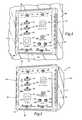
- FIG. 1is a front elevation view of one embodiment of the media appliance presented herein mounted to a wall;
- FIG. 2is a front perspective view of the media appliance presented in FIG. 1 ;
- FIG. 3is a rear elevation view of the media appliance presented in FIG. 1 ;
- FIG. 4is a front perspective view of a housing associated with the media appliance presented in FIG. 1 ;
- FIG. 5is schematic representation of one embodiment of the media appliance.
- the media appliance 10is mounted within a wall 12 and includes a housing 14 , which, as shown, is a utility box 16 having an open end 18 and four side walls 20 , 22 , 24 , 26 as well as a rear wall 28 , which is opposite the open end 18 .
- a panel 30which is configured to substantially mount flush with the wall 12 , mates with the open end 18 of the utility box 16 to form a front portion of the housing 14 .
- the panel 30includes vents and, in particular, vents 32 , 34 , 36 , 38 . Although, it should be appreciated that any configuration of vents may be utilized.
- a plurality of mounting holesare located in the panel 30 to accept fasteners, such as screws, which are driven into corresponding mounting holes at an edge of the open end 18 of the utility box 16 .
- fastenerssuch as screws
- four mounting holes 40 , 42 , 44 , 46 and four respective screws 48 , 50 , 52 , 54are employed to secure the panel 30 .
- the utility box 16may include wall mounting holes and corresponding fasteners and brackets for securing the media appliance 10 within the wall 12 .
- the utility box 16includes fasteners 56 , 58 , 60 , 62 for mating with mounting holes 64 , 66 , 68 , 70 at flange 72 which extends from the open end 18 of the utility box 16 .
- Portsdisposed within respective openings defined by the housing, receive respective optio-electric connectors, which may be optical or electrical, for example, that include optio-electrically conductive elements.
- the portsare configured to provide a connection to external audio-visual devices, such as televisions, and external sources of signal for the external audio-visual devices, such as coaxial cable, fiber, ethernet, USB devices, etc.
- the ports and associated optio-electric connectorsmay include RJ45, serial, IR Input, service/control, USB, video, ethernet, L/R audio cable, and digital audio optical.
- the panel 30includes openings 76 , 78 , 80 , 82 , 84 , 86 , 88 for corresponding ports 96 , 98 , 100 , 102 , 104 , 106 , 108 , 110 , which further correspond to the respective following optio-electric connectors: video output (HDMI-HDCP), video input (HDMI-HDCP), video input (HDMI-HDCP), ethernet, display control (ethernet), digital audio, left audio output, and right audio output.
- video outputHDMI-HDCP
- HDMI-HDCPvideo input
- HDMI-HDCPvideo input
- ethernetethernet
- display controlethernet
- digital audioleft audio output, and right audio output.
- openings 112 , 114 , 116 , 118 , 120 for corresponding ports 122 , 124 , 126 , 128 , 130which further correspond to the respective following optio-electric connectors: power, ethernet, ethernet, RJ45, and coaxial cable.
- powerethernet
- ethernetethernet
- RJ45coaxial cable
- the optio-electrically conductive elementscouple an external source of signal to the circuit board and processor 150 or couple an external audio-visual device, such as a television or music player, to the processor 150 .
- all output sourcesare located on the panel 30 and input sources are located on the panel 30 and in the utility box 16 , whether a side wall 20 , 22 , 24 , 26 or a rear wall 28 , as shown.
- a media appliance 10which includes set-top box functionality and/or media player functionality, is depicted.
- the media set-top/back box and media player functionalitiesare embodied on a processor 150 and memory 152 having processor-executable instructions stored thereon, for example.
- the set-top box functionalityprovides for turning a received signal into content which is then displayed on the television screen or other display device, as well as hotel gateway and menu services and video-on-demand, for example.
- the media player functionalitymay represent any type of consumer electronics device that is capable of storing and playing digital media or permitting digital media to pass therethrough.
- storage 154provides local audio and video files to the processor 150 or other hardware/software/firmware configuration.
- the media appliance 10operates under the power of a power supply 156 , which may convert the wall power provided by a source via port 122 to an acceptable voltage for powering circuitry. Alternatively, power over ethernet via port 124 , 126 may be utilized eliminating the need for port 122 .
- Port 128provides an input signal to the media player and the media engine by way of an RF front end circuit portion 158 , which may, for example, processes signals from coaxial cable.
- ports 124 , 126provide the ethernet interface to the media engine. As shown, all ports 122 , 124 , 126 , 128 , 130 are coupled to the processor, which may more generally be a circuit board.
- a control interface 160 between the processor 150 and the televisionutilizes port 106 to provide control and interface with VOD systems, if required. It should be appreciated that VOD may require an additional or separate port in some instances.
- ports 96 , 98 , 100 , 102 , 104 , 108 , 110which further correspond to the respective following optio-electric connectors: video output (HDMI-HDCP), video input (HDMI-HDCP), video input (HDMI-HDCP), ethernet, digital audio, left audio output, and right audio output.
- LED indicatorsmay be provided.
- a transceivermay be provided for wireless communication with the media appliance 10 .
- control of the media appliance 10may be achieved through the television and a graphical user interface and/or television remote controller.
- the media appliancetherefore accommodates electrical wiring for television and media systems that require numerous cables to connected between the media appliance (Cable STB, Satellite STB, game console, IP streaming player, computer, DVD, Blueray, etc) and display device, such as television.
- the media applianceCable STB, Satellite STB, game console, IP streaming player, computer, DVD, Blueray, etc
- display devicesuch as television.
- set-top boxescannot set on top of the display device, and if the display is wall mounted, a significant number of cables are routed to the back of the display, either with construction costs for hiding cables, or with the cables visible.
- the media appliancemay be located in the same room, or in a different location in a dwelling. In these environments, the construction provides only cosmetic treatment of a traditional cable solution between two devices.
- a system and methodare provided for the media appliance to be located behind the display device, and incorporated into the infrastructure of the facility.
- the media applianceincorporates in-wall components that provide the media generation, or receiving bridge from other broadcasting/transmitting devices to the in-wall media appliance or device.
- the media applianceprovides user accessible inputs and outputs for connection to the display device or other media sources connecting into the media appliance.
- the in-wall media appliancecan provide integrated display control that allows the infrastructure approach to connect and control the display device in a single integrated solution.
- the wall applianceis designed to be hidden from the user. These units will utilize the television screen for the user to control and navigate the player's function. A tight integration with the television set is required so that the users can seamlessly move from watching TV, selecting set top sources, listening to music, controlling various automation and securities, and, browsing the internet through the set top box.
- the interfaces on these in wall media appliancesmay include a control interface, an audio interface and a video interface.
- the media appliance to TV control interfacecan be CEC or a simple serial link such as RS232/422.
- HDMIis the preferred interface for audio and video.
- Analog video and audio interfacecan also be provided for ease of integration with the TVs.
- the solution outlinedis conceived as a utility to address the convergence of media (video, audio, graphical data, control) and develop an integrated infrastructure approach to bridge these media types of a display device in a near-zero footprint device. It incorporates the integration of various media appliances including the set-top box in a thin in-wall appliance.
- the media applianceprovides a media infrastructure device that provides the connectivity, processing and fully operational connected media device, in an in-wall or flush-mount solution.
- the productcan be mounted behind the wall-mounted display device, or as an infrastructure panel near the display device, resulting in a zero or near zero footprint device.
- the media appliance or devicemay serve as an end-point media receiver from other devices connected, or as the complete stand-alone device providing the media and content for the display device.
- Related applicationsinclude in-wall media player, cable or satellite set-top-box Ethernet and other media cable connected media device at point of distribution, device for monitors or displays for computing, digital signage or information signage. Thin, wall mounted displays or televisions for low profile mounting.
- In-wall connectivity panel for user connected devicesmay include an in-wall casement, media player or other media generating device, video output connectors, receiving unit for control (IR, RF, Bluetooth or other wireless control method), power source, display control, cable, satellite, or IP set-top box, streaming audio player, data and Internet connectors, and cover.
Landscapes
- Engineering & Computer Science (AREA)
- Multimedia (AREA)
- Signal Processing (AREA)
- Microelectronics & Electronic Packaging (AREA)
- Power Engineering (AREA)
- Structural Engineering (AREA)
- Civil Engineering (AREA)
- Computer Networks & Wireless Communication (AREA)
- Architecture (AREA)
- Physics & Mathematics (AREA)
- Thermal Sciences (AREA)
- Two-Way Televisions, Distribution Of Moving Picture Or The Like (AREA)
- Devices For Indicating Variable Information By Combining Individual Elements (AREA)
Abstract
Description
Claims (7)
Priority Applications (5)
| Application Number | Priority Date | Filing Date | Title |
|---|---|---|---|
| US14/306,000US9007744B2 (en) | 2010-07-16 | 2014-06-16 | Media appliance and method for use of same |
| US14/598,796US9095057B2 (en) | 2010-07-16 | 2015-01-16 | Media appliance and method for use of same |
| US14/686,634US9252572B2 (en) | 2010-07-16 | 2015-04-14 | Media appliance and method for use of same |
| US14/997,941US9769519B2 (en) | 2010-07-16 | 2016-01-18 | Media appliance and method for use of same |
| US15/706,465US10616641B2 (en) | 2010-07-16 | 2017-09-15 | Media appliance and method for use of same |
Applications Claiming Priority (3)
| Application Number | Priority Date | Filing Date | Title |
|---|---|---|---|
| US36499710P | 2010-07-16 | 2010-07-16 | |
| US13/185,484US8755174B2 (en) | 2010-07-16 | 2011-07-18 | Media appliance and method for use of same |
| US14/306,000US9007744B2 (en) | 2010-07-16 | 2014-06-16 | Media appliance and method for use of same |
Related Parent Applications (1)
| Application Number | Title | Priority Date | Filing Date |
|---|---|---|---|
| US13/185,484ContinuationUS8755174B2 (en) | 2010-07-16 | 2011-07-18 | Media appliance and method for use of same |
Related Child Applications (2)
| Application Number | Title | Priority Date | Filing Date |
|---|---|---|---|
| US14/598,796ContinuationUS9095057B2 (en) | 2010-07-16 | 2015-01-16 | Media appliance and method for use of same |
| US14/686,634ContinuationUS9252572B2 (en) | 2010-07-16 | 2015-04-14 | Media appliance and method for use of same |
Publications (2)
| Publication Number | Publication Date |
|---|---|
| US20140293515A1 US20140293515A1 (en) | 2014-10-02 |
| US9007744B2true US9007744B2 (en) | 2015-04-14 |
Family
ID=45466820
Family Applications (4)
| Application Number | Title | Priority Date | Filing Date |
|---|---|---|---|
| US13/185,484ActiveUS8755174B2 (en) | 2010-07-16 | 2011-07-18 | Media appliance and method for use of same |
| US14/306,000ActiveUS9007744B2 (en) | 2010-07-16 | 2014-06-16 | Media appliance and method for use of same |
| US14/598,796Expired - Fee RelatedUS9095057B2 (en) | 2010-07-16 | 2015-01-16 | Media appliance and method for use of same |
| US14/686,634ActiveUS9252572B2 (en) | 2010-07-16 | 2015-04-14 | Media appliance and method for use of same |
Family Applications Before (1)
| Application Number | Title | Priority Date | Filing Date |
|---|---|---|---|
| US13/185,484ActiveUS8755174B2 (en) | 2010-07-16 | 2011-07-18 | Media appliance and method for use of same |
Family Applications After (2)
| Application Number | Title | Priority Date | Filing Date |
|---|---|---|---|
| US14/598,796Expired - Fee RelatedUS9095057B2 (en) | 2010-07-16 | 2015-01-16 | Media appliance and method for use of same |
| US14/686,634ActiveUS9252572B2 (en) | 2010-07-16 | 2015-04-14 | Media appliance and method for use of same |
Country Status (1)
| Country | Link |
|---|---|
| US (4) | US8755174B2 (en) |
Cited By (2)
| Publication number | Priority date | Publication date | Assignee | Title |
|---|---|---|---|---|
| US9252572B2 (en) | 2010-07-16 | 2016-02-02 | Enseo, Inc. | Media appliance and method for use of same |
| US20160134928A1 (en)* | 2010-07-16 | 2016-05-12 | Enseo, Inc. | Media Appliance and Method for Use of Same |
Families Citing this family (40)
| Publication number | Priority date | Publication date | Assignee | Title |
|---|---|---|---|---|
| US8315266B1 (en)* | 2012-03-02 | 2012-11-20 | Google Inc. | Extending a local area network |
| WO2014019193A1 (en) | 2012-08-02 | 2014-02-06 | 华为终端有限公司 | Integrated terminal and method for providing multi-service therefrom |
| CN102970590B (en)* | 2012-10-31 | 2017-02-22 | 常州机电职业技术学院 | Flat-panel television, computer host and set-top box integrated device |
| US9112298B1 (en)* | 2013-06-09 | 2015-08-18 | Premier Manufacturing Group, Inc. | Apparatus for providing utility receptacles and cables at a selected location on a workstation |
| CN203859818U (en)* | 2014-04-08 | 2014-10-01 | 深圳Tcl新技术有限公司 | Television set |
| MX365276B (en)* | 2014-05-07 | 2019-05-29 | Hubbell Inc | Integrated modular multimedia system in wall-box format. |
| US9300895B2 (en)* | 2014-08-05 | 2016-03-29 | Echostar Uk Holdings Limited | Systems, methods, and apparatus for facilitating expansion of media device interface capabilities |
| US9774815B2 (en)* | 2014-09-12 | 2017-09-26 | Bobby L. Bynum | Locking mount for set top box |
| CN104363522A (en)* | 2014-10-30 | 2015-02-18 | 成都康特电子高新科技有限责任公司 | High-reliability internetwork connector based on broadcast television network system |
| CN104767949A (en)* | 2014-11-08 | 2015-07-08 | 晶晨半导体(上海)有限公司 | Split type television |
| US9565493B2 (en) | 2015-04-30 | 2017-02-07 | Shure Acquisition Holdings, Inc. | Array microphone system and method of assembling the same |
| US9554207B2 (en) | 2015-04-30 | 2017-01-24 | Shure Acquisition Holdings, Inc. | Offset cartridge microphones |
| EP3436858A4 (en) | 2016-04-01 | 2019-12-04 | Commscope Technologies LLC | FIBER OUTPUT AND HYBRID ELECTRIC |
| CN106708213A (en)* | 2016-12-23 | 2017-05-24 | 安徽康海时代科技股份有限公司 | RJ45 type serial server with constant-voltage protection effect |
| CN106682543A (en)* | 2016-12-23 | 2017-05-17 | 安徽康海时代科技股份有限公司 | RJ45 type serial server with redundant isolation protection effect |
| US10367948B2 (en) | 2017-01-13 | 2019-07-30 | Shure Acquisition Holdings, Inc. | Post-mixing acoustic echo cancellation systems and methods |
| CN107168483A (en)* | 2017-06-22 | 2017-09-15 | 安徽康海时代科技股份有限公司 | The serial server of four net of RJ45 types eight |
| CN107239118A (en)* | 2017-06-22 | 2017-10-10 | 安徽康海时代科技股份有限公司 | The serial server of four net of RJ45 types 16 |
| CN107357365A (en)* | 2017-06-22 | 2017-11-17 | 安徽康海时代科技股份有限公司 | The double serial servers of net eight of RJ45 types |
| CN107229314A (en)* | 2017-06-22 | 2017-10-03 | 安徽康海时代科技股份有限公司 | The double net double-serial port servers of RJ45 types |
| CN107168470A (en)* | 2017-06-22 | 2017-09-15 | 安徽康海时代科技股份有限公司 | The double serial servers of net 16 of RJ45 types |
| CN112335261B (en) | 2018-06-01 | 2023-07-18 | 舒尔获得控股公司 | Patterned microphone array |
| US11297423B2 (en) | 2018-06-15 | 2022-04-05 | Shure Acquisition Holdings, Inc. | Endfire linear array microphone |
| CN108741798A (en)* | 2018-08-17 | 2018-11-06 | 上海倾寅视听科技有限公司 | A kind of intelligent electric concealing device |
| US11310596B2 (en) | 2018-09-20 | 2022-04-19 | Shure Acquisition Holdings, Inc. | Adjustable lobe shape for array microphones |
| US11558693B2 (en) | 2019-03-21 | 2023-01-17 | Shure Acquisition Holdings, Inc. | Auto focus, auto focus within regions, and auto placement of beamformed microphone lobes with inhibition and voice activity detection functionality |
| CN113841419B (en) | 2019-03-21 | 2024-11-12 | 舒尔获得控股公司 | Ceiling array microphone enclosure and associated design features |
| WO2020191380A1 (en) | 2019-03-21 | 2020-09-24 | Shure Acquisition Holdings,Inc. | Auto focus, auto focus within regions, and auto placement of beamformed microphone lobes with inhibition functionality |
| CN114051738B (en) | 2019-05-23 | 2024-10-01 | 舒尔获得控股公司 | Steerable speaker array, system and method thereof |
| WO2020243471A1 (en) | 2019-05-31 | 2020-12-03 | Shure Acquisition Holdings, Inc. | Low latency automixer integrated with voice and noise activity detection |
| EP4018680A1 (en) | 2019-08-23 | 2022-06-29 | Shure Acquisition Holdings, Inc. | Two-dimensional microphone array with improved directivity |
| US10841121B1 (en) | 2019-09-30 | 2020-11-17 | Hilton International Holding Llc | Hospitality system and method of using the same |
| WO2021087377A1 (en) | 2019-11-01 | 2021-05-06 | Shure Acquisition Holdings, Inc. | Proximity microphone |
| US11250872B2 (en) | 2019-12-14 | 2022-02-15 | International Business Machines Corporation | Using closed captions as parallel training data for customization of closed captioning systems |
| CN111104354B (en)* | 2019-12-20 | 2022-03-22 | 威创集团股份有限公司 | Digital audio-video connector and interface thereof |
| US11552611B2 (en) | 2020-02-07 | 2023-01-10 | Shure Acquisition Holdings, Inc. | System and method for automatic adjustment of reference gain |
| US11706562B2 (en) | 2020-05-29 | 2023-07-18 | Shure Acquisition Holdings, Inc. | Transducer steering and configuration systems and methods using a local positioning system |
| EP4285605A1 (en) | 2021-01-28 | 2023-12-06 | Shure Acquisition Holdings, Inc. | Hybrid audio beamforming system |
| WO2023059655A1 (en) | 2021-10-04 | 2023-04-13 | Shure Acquisition Holdings, Inc. | Networked automixer systems and methods |
| US12250526B2 (en) | 2022-01-07 | 2025-03-11 | Shure Acquisition Holdings, Inc. | Audio beamforming with nulling control system and methods |
Citations (15)
| Publication number | Priority date | Publication date | Assignee | Title |
|---|---|---|---|---|
| US5599206A (en) | 1995-08-04 | 1997-02-04 | The Whitaker Corporation | Modular jack subassembly for use in a network outlet |
| US5721394A (en) | 1996-07-12 | 1998-02-24 | Mulks; Robert | Flush mount multiport connection box |
| US5886732A (en) | 1995-11-22 | 1999-03-23 | Samsung Information Systems America | Set-top electronics and network interface unit arrangement |
| US6420964B1 (en) | 1999-03-25 | 2002-07-16 | Matsushita Electric Industrial Co., Ltd. | Informational outlet and lines collection module |
| US6750398B1 (en) | 2002-03-26 | 2004-06-15 | Michael T. Richardson | Apparatus for recessing an electrical device in a wall |
| US6856043B2 (en) | 2000-12-28 | 2005-02-15 | Intel Corporation | Audio system with removable, active faceplate |
| US6943295B2 (en) | 2003-07-19 | 2005-09-13 | Greg Herth | Low voltage electrical box |
| US20060098638A1 (en) | 2001-10-11 | 2006-05-11 | Serconet Ltd. | Outlet with analog signal adapter, a method for use thereof and a network using said outlet |
| US20070275595A1 (en) | 2004-02-16 | 2007-11-29 | Serconet Ltd. | Outlet add-on module |
| US20080205606A1 (en) | 2002-11-13 | 2008-08-28 | Serconet Ltd. | Addressable outlet, and a network using the same |
| US20090161322A1 (en)* | 2007-12-21 | 2009-06-25 | Hughes Robert M | Front access enclosure |
| US7612653B2 (en) | 2006-08-01 | 2009-11-03 | Tyco Electronics Corporation | Wall-mounted network outlet |
| US20100226100A1 (en)* | 2009-03-05 | 2010-09-09 | Yen International, Llc | Modular multimedia management and distribution system |
| US20110283120A1 (en) | 2006-08-02 | 2011-11-17 | American Megatrends, Inc. | Ac-powered in-wall computing device with power-line networking capabilities |
| US8755174B2 (en) | 2010-07-16 | 2014-06-17 | Ensco, Inc. | Media appliance and method for use of same |
- 2011
- 2011-07-18USUS13/185,484patent/US8755174B2/enactiveActive
- 2014
- 2014-06-16USUS14/306,000patent/US9007744B2/enactiveActive
- 2015
- 2015-01-16USUS14/598,796patent/US9095057B2/ennot_activeExpired - Fee Related
- 2015-04-14USUS14/686,634patent/US9252572B2/enactiveActive
Patent Citations (15)
| Publication number | Priority date | Publication date | Assignee | Title |
|---|---|---|---|---|
| US5599206A (en) | 1995-08-04 | 1997-02-04 | The Whitaker Corporation | Modular jack subassembly for use in a network outlet |
| US5886732A (en) | 1995-11-22 | 1999-03-23 | Samsung Information Systems America | Set-top electronics and network interface unit arrangement |
| US5721394A (en) | 1996-07-12 | 1998-02-24 | Mulks; Robert | Flush mount multiport connection box |
| US6420964B1 (en) | 1999-03-25 | 2002-07-16 | Matsushita Electric Industrial Co., Ltd. | Informational outlet and lines collection module |
| US6856043B2 (en) | 2000-12-28 | 2005-02-15 | Intel Corporation | Audio system with removable, active faceplate |
| US20060098638A1 (en) | 2001-10-11 | 2006-05-11 | Serconet Ltd. | Outlet with analog signal adapter, a method for use thereof and a network using said outlet |
| US6750398B1 (en) | 2002-03-26 | 2004-06-15 | Michael T. Richardson | Apparatus for recessing an electrical device in a wall |
| US20080205606A1 (en) | 2002-11-13 | 2008-08-28 | Serconet Ltd. | Addressable outlet, and a network using the same |
| US6943295B2 (en) | 2003-07-19 | 2005-09-13 | Greg Herth | Low voltage electrical box |
| US20070275595A1 (en) | 2004-02-16 | 2007-11-29 | Serconet Ltd. | Outlet add-on module |
| US7612653B2 (en) | 2006-08-01 | 2009-11-03 | Tyco Electronics Corporation | Wall-mounted network outlet |
| US20110283120A1 (en) | 2006-08-02 | 2011-11-17 | American Megatrends, Inc. | Ac-powered in-wall computing device with power-line networking capabilities |
| US20090161322A1 (en)* | 2007-12-21 | 2009-06-25 | Hughes Robert M | Front access enclosure |
| US20100226100A1 (en)* | 2009-03-05 | 2010-09-09 | Yen International, Llc | Modular multimedia management and distribution system |
| US8755174B2 (en) | 2010-07-16 | 2014-06-17 | Ensco, Inc. | Media appliance and method for use of same |
Non-Patent Citations (2)
| Title |
|---|
| "Jack PC-The Future of Computing." Chip PC Technologies. n/d Web. Jul. 19, 2011. |
| "Jack PC—The Future of Computing." Chip PC Technologies. n/d Web. Jul. 19, 2011. |
Cited By (4)
| Publication number | Priority date | Publication date | Assignee | Title |
|---|---|---|---|---|
| US9252572B2 (en) | 2010-07-16 | 2016-02-02 | Enseo, Inc. | Media appliance and method for use of same |
| US20160134928A1 (en)* | 2010-07-16 | 2016-05-12 | Enseo, Inc. | Media Appliance and Method for Use of Same |
| US9769519B2 (en)* | 2010-07-16 | 2017-09-19 | Enseo, Inc. | Media appliance and method for use of same |
| US10616641B2 (en) | 2010-07-16 | 2020-04-07 | Enseo, Inc. | Media appliance and method for use of same |
Also Published As
| Publication number | Publication date |
|---|---|
| US9095057B2 (en) | 2015-07-28 |
| US20140293515A1 (en) | 2014-10-02 |
| US8755174B2 (en) | 2014-06-17 |
| US20150124387A1 (en) | 2015-05-07 |
| US9252572B2 (en) | 2016-02-02 |
| US20150222098A1 (en) | 2015-08-06 |
| US20120014049A1 (en) | 2012-01-19 |
Similar Documents
| Publication | Publication Date | Title |
|---|---|---|
| US10616641B2 (en) | Media appliance and method for use of same | |
| US9252572B2 (en) | Media appliance and method for use of same | |
| US8411208B2 (en) | Attached device control on television event | |
| US9544640B2 (en) | Wireless theater system | |
| KR100373198B1 (en) | TV receiver interface system | |
| US20070220560A1 (en) | Audio/video transmission system and method | |
| JP2002027348A (en) | AV system and its function expansion module | |
| US20110191810A1 (en) | Method and System for Distribution of Computer and Entertainment Information | |
| US6847411B2 (en) | Modular television for providing a distinguishable sound according to a selection of a module and/or a module function | |
| US8577484B2 (en) | Customizable media device | |
| US10091604B2 (en) | Generation and presentation of multimedia signals having improved audio | |
| US20080085006A1 (en) | Integrated multi-channel audio box | |
| US20200099883A1 (en) | Television frame assembly | |
| US20030060080A1 (en) | Connector for an audio/visual display monitor | |
| US20120137338A1 (en) | Decoder vesa mounting assembly | |
| CN218450224U (en) | Multifunctional audio and video signal extension device | |
| US20120105734A1 (en) | Multi-Panel Display Device | |
| CN201078826Y (en) | Improved structure of video-audio signal extender | |
| US20140184930A1 (en) | System and Method for Providing Power to a Television Accessory | |
| JP3208588U (en) | Cable harness and television receiver using the same | |
| CN205793088U (en) | A kind of split type Set Top Box | |
| EP1874083A1 (en) | A sound box integrated multi-channel | |
| US20120217396A1 (en) | Flexible and convenient ir emitter device | |
| KR200412945Y1 (en) | Computer case | |
| US20190199959A1 (en) | Television frame assembly |
Legal Events
| Date | Code | Title | Description |
|---|---|---|---|
| AS | Assignment | Owner name:ENSEO, INC., TEXAS Free format text:ASSIGNMENT OF ASSIGNORS INTEREST;ASSIGNORS:OGLE, VANESSA;JOHNS, JEFF;FANG, BILL;SIGNING DATES FROM 20110725 TO 20110726;REEL/FRAME:034120/0936 | |
| STCF | Information on status: patent grant | Free format text:PATENTED CASE | |
| AS | Assignment | Owner name:SILICON VALLEY BANK, CALIFORNIA Free format text:SECURITY INTEREST;ASSIGNOR:ENSEO, INC.;REEL/FRAME:043210/0881 Effective date:20170712 | |
| MAFP | Maintenance fee payment | Free format text:PAYMENT OF MAINTENANCE FEE, 4TH YR, SMALL ENTITY (ORIGINAL EVENT CODE: M2551) Year of fee payment:4 | |
| AS | Assignment | Owner name:ENSEO, LLC, TEXAS Free format text:CHANGE OF NAME;ASSIGNOR:ENSEO, INC.;REEL/FRAME:055139/0530 Effective date:20200313 | |
| AS | Assignment | Owner name:PROSPECT CAPITAL CORPORATION, NEW YORK Free format text:SECURITY INTEREST;ASSIGNORS:ENSEO, LLC;CATAPULT TECHNOLOGIES, LLC;REEL/FRAME:056462/0174 Effective date:20210602 | |
| AS | Assignment | Owner name:ENSEO, LLC, TEXAS Free format text:RELEASE BY SECURED PARTY;ASSIGNOR:SILICON VALLEY BANK;REEL/FRAME:056445/0915 Effective date:20210602 | |
| MAFP | Maintenance fee payment | Free format text:PAYMENT OF MAINTENANCE FEE, 8TH YR, SMALL ENTITY (ORIGINAL EVENT CODE: M2552); ENTITY STATUS OF PATENT OWNER: SMALL ENTITY Year of fee payment:8 |