US9007305B2 - Optical navigation system and method of estimating motion with optical lift detection - Google Patents
Optical navigation system and method of estimating motion with optical lift detectionDownload PDFInfo
- Publication number
- US9007305B2 US9007305B2US12/984,556US98455611AUS9007305B2US 9007305 B2US9007305 B2US 9007305B2US 98455611 AUS98455611 AUS 98455611AUS 9007305 B2US9007305 B2US 9007305B2
- Authority
- US
- United States
- Prior art keywords
- light
- optical
- target surface
- plate
- prism
- Prior art date
- Legal status (The legal status is an assumption and is not a legal conclusion. Google has not performed a legal analysis and makes no representation as to the accuracy of the status listed.)
- Active, expires
Links
Images


Classifications
- G—PHYSICS
- G06—COMPUTING OR CALCULATING; COUNTING
- G06F—ELECTRIC DIGITAL DATA PROCESSING
- G06F3/00—Input arrangements for transferring data to be processed into a form capable of being handled by the computer; Output arrangements for transferring data from processing unit to output unit, e.g. interface arrangements
- G06F3/01—Input arrangements or combined input and output arrangements for interaction between user and computer
- G06F3/03—Arrangements for converting the position or the displacement of a member into a coded form
- G06F3/0304—Detection arrangements using opto-electronic means
- G06F3/0317—Detection arrangements using opto-electronic means in co-operation with a patterned surface, e.g. absolute position or relative movement detection for an optical mouse or pen positioned with respect to a coded surface
- G—PHYSICS
- G06—COMPUTING OR CALCULATING; COUNTING
- G06F—ELECTRIC DIGITAL DATA PROCESSING
- G06F3/00—Input arrangements for transferring data to be processed into a form capable of being handled by the computer; Output arrangements for transferring data from processing unit to output unit, e.g. interface arrangements
- G06F3/01—Input arrangements or combined input and output arrangements for interaction between user and computer
- G06F3/03—Arrangements for converting the position or the displacement of a member into a coded form
- G06F3/033—Pointing devices displaced or positioned by the user, e.g. mice, trackballs, pens or joysticks; Accessories therefor
- G06F3/0354—Pointing devices displaced or positioned by the user, e.g. mice, trackballs, pens or joysticks; Accessories therefor with detection of 2D relative movements between the device, or an operating part thereof, and a plane or surface, e.g. 2D mice, trackballs, pens or pucks
- G06F3/03543—Mice or pucks
Definitions
- Optical navigation systemsoperate to estimate movements between the optical navigation systems and target surfaces to perform tracking operations.
- An optical navigation systemuses a light source, such as a light-emitting diode (LED) or a laser diode, and an image sensor to successively capture frames of image data of a target surface.
- the optical navigation systemcompares the successive image frames and estimates the relative movements between the optical navigation system and the target surface based on the comparison between the current image frame and a previous image frame. The comparison is based on detecting and computing displacements of features in the captured frames of image data.
- these featuresare usually interference images produced by a laser spot impinging on the target surface.
- Optical navigation systemsare commonly used in optical computer mice to track the movements of the mice relative to the surfaces on which the mice are manually manipulated.
- an optical mouseneeds to be on the target surface since errors are introduced when the distance between the image sensor of the optical navigation system and the target surface is significantly increased, i.e., when the optical mouse has been lifted from the target surface.
- the optical interference images used for motion estimationgrow as the distance between the image sensor of the system and the target surface is increased. Consequently, the navigation system can still be responsive after the optical mouse has been lifted from the target surface, which means erroneous motion estimates will be made by the navigation system.
- the optical characteristics of the interference imagesdo not allow a meaningful solution to the issue of lift detection using the image sensor of the optical navigation system.
- a separate sensing mechanismsuch as a mechanical switch is needed to detect when the optical mouse is lifted from a target surface.
- An optical navigation system and method of estimating motionuses a plate with an aperture, a photodetector and an optical system for optical lift detection.
- the optical systemis configured to direct an input light to a target surface through the aperture of the plate and to direct the input light reflected from the target surface and transmitted back through the aperture of the plate toward the photodetector to be detected by the photodetector.
- the input light detected at the photodetectorindicates that the optical navigation system has not been lifted from the target surface. Conversely, no light (except for negligible light) detected at the photodetector indicates that the optical navigation system has been lifted from the target surface.
- An optical navigation system in accordance with an embodiment of the inventioncomprises a light source, an image sensor and a lift detection unit.
- the light sourceis configured to generate light.
- the image sensoris positioned to receive a first portion of the light reflected from a target surface.
- the image sensoris configured to generate frames of image data in response to the received first portion of the light for motion estimation.
- the lift detection unitcomprises a plate with an aperture, a photodetector and an optical system.
- the photodetectoris positioned over the plate.
- the optical systemis positioned over the plate to receive a second portion of the light from the light source.
- the optical systemis configured to direct the second portion of the light through the aperture of the plate.
- the optical systemis further configured to direct the second portion of the light reflected from the target surface and transmitted back through the aperture of the plate toward the photodetector to be detected by the photodetector.
- An optical navigation systemin accordance with an embodiment of the invention comprises a plate with an aperture, a photodetector and an optical system.
- the photodetector and the optical systemare positioned over the plate.
- the optical systemcomprises first, second and third prisms.
- the first prismis positioned to receive an input light.
- the first prismis configured and orientated to refract the input light through the aperture of the plate.
- the second prismis positioned to receive the input light reflected from a target surface and transmitted back through the aperture of the plate.
- the second prismis configured and orientated to refract the input light to a predefined direction.
- the third prismis positioned to receive the input light from the second prism.
- the third prismis configured to refract the input light toward the photodetector to be detected by the photodetector.
- a method of estimating motionin accordance with an embodiment of the invention comprising generating light, directing a first portion of the light toward a target surface, receiving the first portion of the light reflected from the target surface at an image sensor for motion estimation, directing a second portion of the light toward the target surface through an aperture positioned over the target surface, directing the second portion of the light reflected from the target surface and transmitted back through the aperture toward a photodetector, and receiving the second portion of the light at the photodetector.
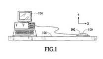
- FIG. 1shows an optical navigation system included in an optical computer mouse in accordance with an embodiment of the invention.
- FIG. 2is a diagram of the optical navigation system in accordance with an embodiment of the invention.
- FIG. 3is a perspective view of a lower plate and an optical system of the optical navigation system in accordance with an embodiment of the invention.
- FIG. 4is a diagram of the optical navigation system of FIG. 2 , showing optical paths of light through the optical navigation system when the optical computer mouse has not been lifted.
- FIG. 5is a diagram of the optical navigation system of FIG. 2 , showing optical paths of light through the optical navigation system when the optical computer mouse has been lifted.
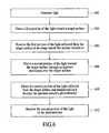
- FIG. 6is a process flow diagram of a method of estimating motion in accordance with an embodiment of the invention.
- an optical navigation system 100in accordance with an embodiment of the invention is described.
- the optical navigation system 100is included in an optical computer mouse 102 , which is connected to a computer 104 .
- the optical navigation system 100is used to track the movements of the optical mouse 102 as the optical mouse is manipulated over a target surface 106 , which may be a glass surface or other optically transparent surface, by a user to control a cursor displayed on the computer 104 .
- the optical navigation system 100can be used in different products for various tracking applications.
- the optical navigation system 100includes an optical lift detection feature to optically detect when the optical mouse 102 has been lifted from the surface in the Z direction.
- the optical lift detection feature of the optical navigation system 100can be implemented using low cost components without the requirement of critical alignment.
- FIG. 2is a sectional view of the optical navigation system 100 .
- the optical navigation system 100includes a navigation unit 210 and a lift detection unit 212 .
- the primary function of the navigation unit 210is to capture frames of image data for motion estimation.
- the primary function of the lift detection unit 212is to detect when the optical mouse 102 with the optical navigation system 100 has been lifted from the target surface 106 .
- the navigation unit 212includes a light source 214 , an optical guide structure 216 and an image sensor 218 .
- the light source 214generates light, which will be used for both motion estimation and lift detection.
- the light source 214is a laser device, such as a vertical-cavity surface-emitting laser (VCSEL), which generates coherent light.
- VCSELvertical-cavity surface-emitting laser
- the light source 214may be a light emitting diode or any other light emitting device.
- the light source 214is positioned to emit light along the X direction into the optical guide structure 216 .
- the optical guide structure 216is an optically transparent structure configured to direct some of the light received from the light source 214 to an imaging area 220 of the target surface 106 .
- the optical guide structure 216is also designed to receive the light reflected off the imaging area 220 of the target surface 106 to transmit the reflected light to the image sensor 218 .
- the optical guide structure 216is designed to transmit some of the light received from the light source 214 to the lift detection unit 212 , which uses this light to detect when the optical mouse 102 , or any other device, with the optical navigation system 100 has been lifted from the target surface 106 .
- the optical guide structure 216is designed to transmit some of the light from the light source 214 to the lift detection unit 212 such that the light is mostly traveling along the X direction.
- the optical guide structure 216may be structurally shaped in any number of configurations, as long as the optical guide structure can optically perform the above-described tasks.
- the optical guide structure 216includes an input port 222 to receive the light emitted from the light source 214 so that the received light is transmitted into the optical guide structure along the X direction.
- the input port 222 of the optical guide structure 216has a convex surface to focus the received light from the light source 214 .
- the optical guide structure 216also includes an intermediate section 224 , which internally reflects the light from the input port 222 so that the light is maintained along the X direction but closer to the bottom of the optical guide structure 216 , i.e., closer to the target surface 106 on which the optical computer mouse 102 is being operated.
- the intermediate section 224 of the optical guide structure 216includes an upper surface 226 , which reflects the light from the input port 222 downward along the Z direction, and a lower surface 228 , which reflects the light from the upper surface 226 back along the X direction.
- the optical guide structure 216also includes an output section 230 , which separates the light from the lower surface 228 so that some of the light can be used for motion estimation and some of the light can be used for lift detection.
- the output section 230includes a reflective surface 232 , which reflects a portion of the light from the lower surface 228 downward along the Z direction toward the imaging area 220 of the target surface 106 for use in motion estimation.
- the output section 230also includes an output port 234 to output a portion of the light from the lower surface 228 along the X direction toward the lift detection unit 212 for use in lift detection.
- the image sensor 218is positioned above the optical guide structure 216 to receive the light reflected off the imaging area 220 of the target surface 106 to capture frames of image data of the target surface. Specifically, the image sensor 218 is positioned over the reflective surface 232 of the optical guide structure 216 to receive the light reflected from the imaging area 220 of the target surface 106 .
- the image sensor 218includes an array of photosensitive pixel elements (not shown), which generate image signals in response to light incident on the elements.
- the image sensor 218may be a charged-coupled device (CCD) image sensor or a complementary metal oxide semiconductor (CMOS) image sensor.
- CMOScomplementary metal oxide semiconductor
- the number of photosensitive pixel elements included in the image sensor 218may vary depending on at least performance requirements of the optical navigation system 100 with respect to optical motion estimation.
- the image sensor 218may include a 30 ⁇ 30 array of active photosensitive pixel elements.
- the lift detection unit 212 of the optical navigation system 100includes a lower plate 236 , an upper plate 238 , an optical system 240 and a photodetector 242 .
- the upper plate 238is positioned over the lower plate 236 such that there is a predefined distance between the plates.
- the lower and upper plates 236 and 238are positioned next to the output port 234 of the optical guide structure 216 . Both the lower and upper plates 236 and 238 are orientated to be parallel along the X direction.
- FIG. 3which is a perspective view of the lower plate 236 and the optical system 240 , the lower plate includes an aperture 244 .
- the aperture 244 of the lower plate 236is rectangular in shape.
- the aperture 244 of the lower plate 236may have a different shape, such as a circular shape.
- the lower and upper plates 236 and 238are optically opaque such that light is block by the plates. Thus, only way for light to pass through the lower plate 236 is through the aperture 244 of the lower plate.
- the lower and upper plates 236 and 238 of the lift detection unit 212may be attached to the housing (not shown) of the optical computer mouse 102 .
- the optical system 240is positioned between the lower and upper plates 236 and 238 to receive the light emitted from the output port 234 of the optical guide structure 216 .
- the optical system 240is configured to direct the received light downward through the aperture 244 of the lower plate 236 at an angle greater than zero with respect to the X axis, which is parallel to the lower plate 236 .
- the light transmitted through the aperture 244 of the lower plate 236is then reflected off the target surface 106 .
- the optical system 240is further configured to receive the light reflected off the target surface and transmitted back through the aperture 244 of the lower plate 236 , and to direct that light to the photodetector 242 , which in the illustrated embodiment is located above the upper plate 238 but not directly over the upper plate.
- the upper plate 238is used to prevent any unwanted light from reaching the photodetector 242 .
- the optical system 242includes three prisms 246 , 248 and 250 , which are positioned between the lower and upper plates 236 and 238 .
- the prisms 246 , 248 and 250are triangular prisms with three major sides.
- the prisms 246 , 248 and 250are right triangular prisms.
- the cross-section of the prisms 246 , 248 and 250is right triangular in shape.
- the non-right angled corners of the prisms 246 , 248 and 250are angled at forty-five degrees (45%).
- these non-right angled corners of the prisms 246 , 248 and 250may be angled at different degrees.
- the prisms 246 , 248 and 250may not be right triangular prisms, and may even not be triangular prisms.
- the first prism 246is positioned between the optical guide structure 216 and the aperture 244 of the lower plate 236 .
- the first prism 246is orientated such that its right angled corner is at the bottom near the lower plate 236 and the hypotenuse side of the prism 246 is facing the output port 234 of the optical guide structure 216 to receive light emitted from the output port.
- the first prism 246refracts the light emitted from the output port 234 of the optical guide structure 216 downward at an angle toward the aperture 244 of the lower plate 236 .
- the second prism 248is positioned such that the aperture 244 of the lower plate 236 is located between the first prism 246 and the second prism 248 .
- the second prism 248is orientated such that its right angled corner is at the bottom near the lower plate 236 and the hypotenuse side of the prism 248 is facing away from the output port 234 of the optical guide structure 216 .
- the second prism 248is positioned to receive the light from the first prism, which has been reflected off the target surface 106 and transmitted back through the aperture 244 of the lower plate 236 .
- the second prism 248refracts the received light so that the refracted light propagates along the X direction toward the third prism 250 .
- the third prism 250is positioned such that the second prism 248 is located between the aperture 244 of the lower plate 236 and the third prism 250 .
- the third prism 250is orientated such that its right angled corner is at the top near the upper plate 238 and the hypotenuse side of the prism 250 is facing away from the output port 234 of the optical guide structure 216 .
- the third prism 250is located such that most of the hypotenuse side of the prism 250 extends out from under the upper plate 238 .
- the third prism 250is positioned to receive the refracted light from the second prism 248 .
- the third prism 250refracts the received light upward so that the refracted light propagates along the Z direction toward the photodetector 242 .
- the photodetector 242is positioned over the third prism 250 to receive the light refracted from the third prism 250 .
- the photodetector 242may be any type of a light sensing device, such as a photodiode or other light intensity sensor.
- the photodetector 242is configured to generate an electrical signal in response to incident light.
- the photodetector 242will receive light from the optical system 240 .
- the photodetector 242will not receive any light from the optical system 240 .
- the electrical signal generated by the photodetector 242 in response to incident lightcan be used to detect when the optical computer mouse 102 has been “lifted” from the target surface 106 .
- a preset threshold for optical power received by the photodetector 242is defined, which will eliminate any error signal generated by stray light.
- the predefined height that defines when the optical computer mouse 106 has been “lifted” from the target surface 106can be adjusted by varying the distances between the prisms 246 , 248 and 250 of the lift detection unit 212 .
- FIG. 4shows optical paths of light through the optical navigation system 100 when the optical computer mouse 102 has not been lifted beyond the predefined height from the target surface 106 .
- the light emitted from the light source 214is transmitted along the X direction into the optical guide structure 216 at the input port 222 .
- the lightis then internally reflected off the upper surface 226 of the optical guide structure 216 downward along the Z direction.
- the lightis then again internally reflected off the lower surface 228 of the optical structure 216 so that the reflected light propagates again along the X direction.
- the lightis then divided into first and second portions of light.
- the first portion of lightis reflected off the reflective surface 232 of the optical guide structure 216 downward toward the imaging area 220 of the target surface 106 .
- This lightis then reflected from the target surface 106 and received by the image sensor 218 to produce frames of image data for motion estimation.
- the second portion of lightis transmitted through output port 234 of the optical guide structure 216 toward the lift detection unit 212 .
- the light emitted from the output port 234 of the optical guide structure 216is then refracted by the first prism 246 of the optical system 240 of the lift detection unit 212 downward through the aperture 244 of the lower plate 236 to the target surface 106 .
- the lightis then reflected upward from the target surface 106 . Due to the close proximity of the target surface 106 to the lower plate 236 , the reflected light is transmitted back through the aperture 244 toward the second prism 248 of the lift detection unit 212 .
- the lightis then refracted by the second prism 248 toward the third prism 250 of the lift detection unit 212 along the X direction.
- the lightis refracted upward along the Z direction toward the photodetector 242 .
- the lightis then detected by the photodetector 242 , which indicates that the computer optical mouse 102 has not been “lifted” from the target surface 106 .
- FIG. 5shows optical paths of light through the optical navigation system 100 when the optical computer mouse 102 has been lifted beyond the predefined height from the target surface 106 .
- the light emitted from the light source 214travels through the optical guide structure 216 in the same manner as described above.
- a first portion of lightis reflected off the target surface 106 and received at the image sensor 218 for motion estimation.
- a second portion of lightis emitted from the output port 234 of the optical guide structure 216 .
- the light emitted from the output port 234is again refracted by the first prism 246 of the lift detection unit 212 downward through the aperture 244 of the lower plate 236 to the target surface 106 .
- the lightis then reflected upward from the target surface 106 .
- the reflected light from the target surface 106is not transmitted back through the aperture 244 of the lower plate 236 . Rather, the reflected light from the target surface 106 is blocked by the lower plate 236 . Thus, the reflected light from the target surface 106 does not reach the photodetector 242 . Consequently, no light (except maybe negligible light) is detected by the photodetector 242 , which indicates that the computer optical mouse 102 has been “lifted” from the target surface 106 .
- the lift detection technique of the optical navigation system 106is independent of the materials and characteristics of the target surface 106 since it only needs to detect the intensity of light reaching the photodetector 242 .
- the lift detection sensitivity of the optical navigation system 100is dependent on the size of the aperture 244 of the lower plate 236 of the lift detection unit 212 .
- the optical navigation system 100can be adjusted to be more sensitive by using a smaller aperture in the lower plate 236 of the lift detection unit 212 .
- a method of estimating motion in accordance with an embodiment of the inventionis described with reference to a process flow diagram of FIG. 6 .
- lightis generated.
- a first portion of the lightis directed toward a target surface.
- the first portion of the light reflected from the target surfaceis received at an image sensor for motion estimation.
- a second portion of the lightis directed toward the target surface through an aperture positioned over the target surface.
- the second portion of the light reflected from the target surface and transmitted back through the apertureis directed toward a photodetector.
- the second portion of the lightis received at the photodetector for lift detection.
Landscapes
- Engineering & Computer Science (AREA)
- General Engineering & Computer Science (AREA)
- Theoretical Computer Science (AREA)
- Human Computer Interaction (AREA)
- Physics & Mathematics (AREA)
- General Physics & Mathematics (AREA)
- Position Input By Displaying (AREA)
- Length Measuring Devices By Optical Means (AREA)
Abstract
Description
Claims (7)
Priority Applications (1)
| Application Number | Priority Date | Filing Date | Title |
|---|---|---|---|
| US12/984,556US9007305B2 (en) | 2006-11-20 | 2011-01-04 | Optical navigation system and method of estimating motion with optical lift detection |
Applications Claiming Priority (2)
| Application Number | Priority Date | Filing Date | Title |
|---|---|---|---|
| US11/602,876US7868281B2 (en) | 2006-11-20 | 2006-11-20 | Optical navigation system and method of estimating motion with optical lift detection |
| US12/984,556US9007305B2 (en) | 2006-11-20 | 2011-01-04 | Optical navigation system and method of estimating motion with optical lift detection |
Related Parent Applications (1)
| Application Number | Title | Priority Date | Filing Date |
|---|---|---|---|
| US11/602,876DivisionUS7868281B2 (en) | 2006-11-20 | 2006-11-20 | Optical navigation system and method of estimating motion with optical lift detection |
Publications (2)
| Publication Number | Publication Date |
|---|---|
| US20110095984A1 US20110095984A1 (en) | 2011-04-28 |
| US9007305B2true US9007305B2 (en) | 2015-04-14 |
Family
ID=38925762
Family Applications (2)
| Application Number | Title | Priority Date | Filing Date |
|---|---|---|---|
| US11/602,876Active2029-05-05US7868281B2 (en) | 2006-11-20 | 2006-11-20 | Optical navigation system and method of estimating motion with optical lift detection |
| US12/984,556Active2029-04-11US9007305B2 (en) | 2006-11-20 | 2011-01-04 | Optical navigation system and method of estimating motion with optical lift detection |
Family Applications Before (1)
| Application Number | Title | Priority Date | Filing Date |
|---|---|---|---|
| US11/602,876Active2029-05-05US7868281B2 (en) | 2006-11-20 | 2006-11-20 | Optical navigation system and method of estimating motion with optical lift detection |
Country Status (4)
| Country | Link |
|---|---|
| US (2) | US7868281B2 (en) |
| CN (1) | CN100576156C (en) |
| GB (2) | GB2443975B (en) |
| TW (2) | TWI391847B (en) |
Families Citing this family (12)
| Publication number | Priority date | Publication date | Assignee | Title |
|---|---|---|---|---|
| KR100620951B1 (en)* | 2004-10-06 | 2006-09-19 | 주식회사 애트랩 | Optical mouse with light shield |
| US10452207B2 (en) | 2005-05-18 | 2019-10-22 | Power2B, Inc. | Displays and information input devices |
| US8610675B2 (en) | 2007-03-14 | 2013-12-17 | Power2B, Inc. | Interactive devices |
| US7868281B2 (en)* | 2006-11-20 | 2011-01-11 | Avago Technologies Ecbu Ip (Singapore) Pte. Ltd. | Optical navigation system and method of estimating motion with optical lift detection |
| US8570194B2 (en) | 2008-09-05 | 2013-10-29 | Microsoft Corporation | Clutch-height adjustment in an optical tracking device |
| SK5917Y1 (en)* | 2010-11-22 | 2011-11-04 | Stefan Valicek | Optics for pencil optical input computer peripheral controller |
| CN102959494B (en) | 2011-06-16 | 2017-05-17 | 赛普拉斯半导体公司 | An optical navigation module with capacitive sensor |
| US8896553B1 (en) | 2011-11-30 | 2014-11-25 | Cypress Semiconductor Corporation | Hybrid sensor module |
| US9377366B2 (en)* | 2013-07-08 | 2016-06-28 | Pixart Imaging Inc. | Navigation device including thermal sensor |
| CN108080293B (en)* | 2018-02-09 | 2024-05-14 | 芜湖立德智兴半导体有限公司 | Six-face detection chip detection device |
| US10888769B2 (en)* | 2018-11-13 | 2021-01-12 | Steelseries Aps | Method and apparatus for enhancing accuracy associated with a gaming accessory in accordance with a distance of the gaming accessory relative to a surface |
| US11886649B2 (en)* | 2021-11-25 | 2024-01-30 | Pixart Imaging Inc. | Optical navigation device |
Citations (42)
| Publication number | Priority date | Publication date | Assignee | Title |
|---|---|---|---|---|
| US4521772A (en) | 1981-08-28 | 1985-06-04 | Xerox Corporation | Cursor control device |
| US4799055A (en) | 1984-04-26 | 1989-01-17 | Symbolics Inc. | Optical Mouse |
| US4920260A (en) | 1988-08-30 | 1990-04-24 | Msc Technologies, Inc. | Detector system for optical mouse |
| US5272685A (en)* | 1989-12-22 | 1993-12-21 | Kabushiki Kaisha Toshiba | Optical system for an information processing apparatus |
| US6078312A (en)* | 1997-07-09 | 2000-06-20 | Gateway 2000, Inc. | Pointing device with absolute and relative positioning capability |
| US6256016B1 (en) | 1997-06-05 | 2001-07-03 | Logitech, Inc. | Optical detection system, device, and method utilizing optical matching |
| US6300612B1 (en) | 1998-02-02 | 2001-10-09 | Uniax Corporation | Image sensors made from organic semiconductors |
| KR20030048254A (en) | 2001-12-11 | 2003-06-19 | 스텝시스템주식회사 | Unified type semiconductor package including light sensor and light source and light mouse having the same |
| US20030112220A1 (en) | 2000-12-15 | 2003-06-19 | Hong-Young Yang | Pen type optical mouse device and method of controlling the same |
| US20040001046A1 (en) | 2002-07-01 | 2004-01-01 | Chen Shu-Fen | Optical mouse |
| US20040051798A1 (en) | 2002-09-18 | 2004-03-18 | Ramakrishna Kakarala | Method for detecting and correcting defective pixels in a digital image sensor |
| US6720595B2 (en) | 2001-08-06 | 2004-04-13 | International Business Machines Corporation | Three-dimensional island pixel photo-sensor |
| US20040130532A1 (en) | 2003-01-07 | 2004-07-08 | Gordon Gary B. | Apparatus for controlling a screen pointer with a frame rate based on velocity |
| US6770863B2 (en) | 2001-10-26 | 2004-08-03 | Agilent Technologies, Inc. | Apparatus and method for three-dimensional relative movement sensing |
| US20050024624A1 (en) | 2003-07-31 | 2005-02-03 | Gruhlke Russell W. | Speckle based sensor for three dimensional navigation |
| US20050052411A1 (en) | 2000-09-29 | 2005-03-10 | Farag Abraham S. | Input device off table switch |
| US20050057492A1 (en) | 2003-08-29 | 2005-03-17 | Microsoft Corporation | Data input device for tracking and detecting lift-off from a tracking surface by a reflected laser speckle pattern |
| US20050190158A1 (en) | 2004-03-01 | 2005-09-01 | Microsoft Corporation | Dynamically adjusting operation of one or more sensors of a computer input device |
| US6940652B2 (en) | 2003-11-21 | 2005-09-06 | Pacer Technology Co., Ltd. | Optical image retrieval method |
| US20050231482A1 (en) | 2004-04-15 | 2005-10-20 | Olivier Theytaz | Multi-light-source illumination system for optical pointing devices |
| US20060028447A1 (en) | 2004-07-30 | 2006-02-09 | Vook Dietrich W | Reducing dust contamination in optical mice |
| US7019733B2 (en) | 2003-03-31 | 2006-03-28 | Ban Kuan Koay | Optical mouse adapted for use on glass surfaces |
| US20060071907A1 (en) | 2004-10-06 | 2006-04-06 | Chul-Yong Joung | Optical pointing device |
| US20060091298A1 (en) | 2004-10-30 | 2006-05-04 | Tong Xie | Tracking separation between an object and a surface using a reducing structure |
| US20060119581A1 (en) | 2002-09-09 | 2006-06-08 | Levy David H | Keyboard improvements |
| US20060119580A1 (en) | 2004-12-07 | 2006-06-08 | Mao-Hsiung Chien | Optical mouse |
| US20060131487A1 (en) | 2004-09-30 | 2006-06-22 | Olivier Mathis | Continuous base beneath optical sensor and optical homodyning system |
| US7081612B1 (en) | 2005-04-13 | 2006-07-25 | Pacer Technology Co., Ltd. | Light projection method and apparatus for an optical mouse |
| US20060176581A1 (en) | 2005-02-04 | 2006-08-10 | Shu-Feng Lu | Light apparatus of an optical mouse with an aperture stop and the light projection method thereof |
| US20060279545A1 (en) | 2005-06-13 | 2006-12-14 | Jeng-Feng Lan | Sensor chip for laser optical mouse and related laser optical mouse |
| US20070008286A1 (en) | 2005-06-30 | 2007-01-11 | Logitech Europe S.A. | Optical displacement detection over varied surfaces |
| GB2429280A (en) | 2005-08-16 | 2007-02-21 | Avago Tech Ecbu Ip | Optical navigation device configured to operate through a transparent layer and to have skating functionality |
| US20070181785A1 (en) | 2006-02-09 | 2007-08-09 | Helbing Rene P | Compact optical navigation module and microlens array therefore |
| US20080158158A1 (en)* | 2006-12-29 | 2008-07-03 | Chiang Sun Cheah | Optical navigation device adapted for navigation on a transparent plate |
| US20080231600A1 (en) | 2007-03-23 | 2008-09-25 | Smith George E | Near-Normal Incidence Optical Mouse Illumination System with Prism |
| US7444005B2 (en)* | 2003-11-04 | 2008-10-28 | Becton, Dickinson And Company | Apparatus and method for using optical mouse engine to determine speed, direction, position of scanned device and to obtain quantitative or qualitative data from same |
| US7460107B1 (en)* | 2003-03-07 | 2008-12-02 | Microsoft Corporation | Computer input device with multi-purpose light guide |
| US7474297B2 (en)* | 2004-03-22 | 2009-01-06 | Avago Technologies Ecbu Ip (Singapore) Pte. | Contaminant-resistant optical mouse and cradle |
| US7791591B2 (en)* | 2006-08-04 | 2010-09-07 | Emcore Corporation | Optical mouse using VCSELs |
| US7791735B2 (en)* | 2007-02-26 | 2010-09-07 | Avago Technologies Ecbu Ip (Singapore) Pte. Ltd. | Pointing device |
| US7868281B2 (en)* | 2006-11-20 | 2011-01-11 | Avago Technologies Ecbu Ip (Singapore) Pte. Ltd. | Optical navigation system and method of estimating motion with optical lift detection |
| US8026900B2 (en) | 2004-09-14 | 2011-09-27 | Atlab Inc. | Optical mouse that detects working surface using code included in illuminated light and control method thereof |
Family Cites Families (2)
| Publication number | Priority date | Publication date | Assignee | Title |
|---|---|---|---|---|
| US694652A (en)* | 1901-07-17 | 1902-03-04 | American Pedometer Company | Pedometer. |
| US7446747B2 (en)* | 2003-09-12 | 2008-11-04 | Intersil Americas Inc. | Multiple channel programmable gamma correction voltage generator |
- 2006
- 2006-11-20USUS11/602,876patent/US7868281B2/enactiveActive
- 2007
- 2007-11-12TWTW96142724Apatent/TWI391847B/enactive
- 2007-11-12TWTW102100045Apatent/TWI536210B/enactive
- 2007-11-20GBGB0722757Apatent/GB2443975B/ennot_activeExpired - Fee Related
- 2007-11-20CNCN200710187722Apatent/CN100576156C/enactiveActive
- 2007-11-20GBGB201103260Apatent/GB2476186B/ennot_activeExpired - Fee Related
- 2011
- 2011-01-04USUS12/984,556patent/US9007305B2/enactiveActive
Patent Citations (46)
| Publication number | Priority date | Publication date | Assignee | Title |
|---|---|---|---|---|
| US4521772A (en) | 1981-08-28 | 1985-06-04 | Xerox Corporation | Cursor control device |
| US4799055A (en) | 1984-04-26 | 1989-01-17 | Symbolics Inc. | Optical Mouse |
| US4920260A (en) | 1988-08-30 | 1990-04-24 | Msc Technologies, Inc. | Detector system for optical mouse |
| US5272685A (en)* | 1989-12-22 | 1993-12-21 | Kabushiki Kaisha Toshiba | Optical system for an information processing apparatus |
| US6256016B1 (en) | 1997-06-05 | 2001-07-03 | Logitech, Inc. | Optical detection system, device, and method utilizing optical matching |
| US6078312A (en)* | 1997-07-09 | 2000-06-20 | Gateway 2000, Inc. | Pointing device with absolute and relative positioning capability |
| US6300612B1 (en) | 1998-02-02 | 2001-10-09 | Uniax Corporation | Image sensors made from organic semiconductors |
| US20050052411A1 (en) | 2000-09-29 | 2005-03-10 | Farag Abraham S. | Input device off table switch |
| US20030112220A1 (en) | 2000-12-15 | 2003-06-19 | Hong-Young Yang | Pen type optical mouse device and method of controlling the same |
| US6720595B2 (en) | 2001-08-06 | 2004-04-13 | International Business Machines Corporation | Three-dimensional island pixel photo-sensor |
| US6770863B2 (en) | 2001-10-26 | 2004-08-03 | Agilent Technologies, Inc. | Apparatus and method for three-dimensional relative movement sensing |
| KR20030048254A (en) | 2001-12-11 | 2003-06-19 | 스텝시스템주식회사 | Unified type semiconductor package including light sensor and light source and light mouse having the same |
| US20040001046A1 (en) | 2002-07-01 | 2004-01-01 | Chen Shu-Fen | Optical mouse |
| US20060119581A1 (en) | 2002-09-09 | 2006-06-08 | Levy David H | Keyboard improvements |
| US20040051798A1 (en) | 2002-09-18 | 2004-03-18 | Ramakrishna Kakarala | Method for detecting and correcting defective pixels in a digital image sensor |
| US20040130532A1 (en) | 2003-01-07 | 2004-07-08 | Gordon Gary B. | Apparatus for controlling a screen pointer with a frame rate based on velocity |
| US6995748B2 (en) | 2003-01-07 | 2006-02-07 | Agilent Technologies, Inc. | Apparatus for controlling a screen pointer with a frame rate based on velocity |
| US7460107B1 (en)* | 2003-03-07 | 2008-12-02 | Microsoft Corporation | Computer input device with multi-purpose light guide |
| US7019733B2 (en) | 2003-03-31 | 2006-03-28 | Ban Kuan Koay | Optical mouse adapted for use on glass surfaces |
| US20050024624A1 (en) | 2003-07-31 | 2005-02-03 | Gruhlke Russell W. | Speckle based sensor for three dimensional navigation |
| US20050057492A1 (en) | 2003-08-29 | 2005-03-17 | Microsoft Corporation | Data input device for tracking and detecting lift-off from a tracking surface by a reflected laser speckle pattern |
| US7444005B2 (en)* | 2003-11-04 | 2008-10-28 | Becton, Dickinson And Company | Apparatus and method for using optical mouse engine to determine speed, direction, position of scanned device and to obtain quantitative or qualitative data from same |
| US6940652B2 (en) | 2003-11-21 | 2005-09-06 | Pacer Technology Co., Ltd. | Optical image retrieval method |
| US20050190158A1 (en) | 2004-03-01 | 2005-09-01 | Microsoft Corporation | Dynamically adjusting operation of one or more sensors of a computer input device |
| US7474297B2 (en)* | 2004-03-22 | 2009-01-06 | Avago Technologies Ecbu Ip (Singapore) Pte. | Contaminant-resistant optical mouse and cradle |
| US20050231482A1 (en) | 2004-04-15 | 2005-10-20 | Olivier Theytaz | Multi-light-source illumination system for optical pointing devices |
| US20060028447A1 (en) | 2004-07-30 | 2006-02-09 | Vook Dietrich W | Reducing dust contamination in optical mice |
| US8026900B2 (en) | 2004-09-14 | 2011-09-27 | Atlab Inc. | Optical mouse that detects working surface using code included in illuminated light and control method thereof |
| US20060131487A1 (en) | 2004-09-30 | 2006-06-22 | Olivier Mathis | Continuous base beneath optical sensor and optical homodyning system |
| US20060071907A1 (en) | 2004-10-06 | 2006-04-06 | Chul-Yong Joung | Optical pointing device |
| US20060091298A1 (en) | 2004-10-30 | 2006-05-04 | Tong Xie | Tracking separation between an object and a surface using a reducing structure |
| US7189985B2 (en)* | 2004-10-30 | 2007-03-13 | Avago Technologies General Ip (Singapore) Pte. Ltd. | Tracking separation between an object and a surface using a reducing structure |
| US20060119580A1 (en) | 2004-12-07 | 2006-06-08 | Mao-Hsiung Chien | Optical mouse |
| US20060176581A1 (en) | 2005-02-04 | 2006-08-10 | Shu-Feng Lu | Light apparatus of an optical mouse with an aperture stop and the light projection method thereof |
| US7142376B2 (en) | 2005-02-04 | 2006-11-28 | Pacer Technology Co., Ltd. | Light apparatus of an optical mouse with an aperture stop and the light projection method thereof |
| US7081612B1 (en) | 2005-04-13 | 2006-07-25 | Pacer Technology Co., Ltd. | Light projection method and apparatus for an optical mouse |
| US20060279545A1 (en) | 2005-06-13 | 2006-12-14 | Jeng-Feng Lan | Sensor chip for laser optical mouse and related laser optical mouse |
| US20070013661A1 (en)* | 2005-06-30 | 2007-01-18 | Olivier Theytaz | Optical displacement detection over varied surfaces |
| US20070008286A1 (en) | 2005-06-30 | 2007-01-11 | Logitech Europe S.A. | Optical displacement detection over varied surfaces |
| GB2429280A (en) | 2005-08-16 | 2007-02-21 | Avago Tech Ecbu Ip | Optical navigation device configured to operate through a transparent layer and to have skating functionality |
| US20070181785A1 (en) | 2006-02-09 | 2007-08-09 | Helbing Rene P | Compact optical navigation module and microlens array therefore |
| US7791591B2 (en)* | 2006-08-04 | 2010-09-07 | Emcore Corporation | Optical mouse using VCSELs |
| US7868281B2 (en)* | 2006-11-20 | 2011-01-11 | Avago Technologies Ecbu Ip (Singapore) Pte. Ltd. | Optical navigation system and method of estimating motion with optical lift detection |
| US20080158158A1 (en)* | 2006-12-29 | 2008-07-03 | Chiang Sun Cheah | Optical navigation device adapted for navigation on a transparent plate |
| US7791735B2 (en)* | 2007-02-26 | 2010-09-07 | Avago Technologies Ecbu Ip (Singapore) Pte. Ltd. | Pointing device |
| US20080231600A1 (en) | 2007-03-23 | 2008-09-25 | Smith George E | Near-Normal Incidence Optical Mouse Illumination System with Prism |
Also Published As
| Publication number | Publication date |
|---|---|
| TW200834394A (en) | 2008-08-16 |
| GB0722757D0 (en) | 2008-01-02 |
| TWI391847B (en) | 2013-04-01 |
| GB201103260D0 (en) | 2011-04-13 |
| GB2443975A (en) | 2008-05-21 |
| TWI536210B (en) | 2016-06-01 |
| GB2476186B (en) | 2011-12-21 |
| US20080117412A1 (en) | 2008-05-22 |
| GB2443975B (en) | 2011-12-21 |
| US20110095984A1 (en) | 2011-04-28 |
| US7868281B2 (en) | 2011-01-11 |
| TW201319877A (en) | 2013-05-16 |
| CN101187841A (en) | 2008-05-28 |
| GB2476186A (en) | 2011-06-15 |
| CN100576156C (en) | 2009-12-30 |
Similar Documents
| Publication | Publication Date | Title |
|---|---|---|
| US9007305B2 (en) | Optical navigation system and method of estimating motion with optical lift detection | |
| US7442916B2 (en) | Lift detection adapted for navigation on a transparent structure | |
| US8138488B2 (en) | System and method for performing optical navigation using scattered light | |
| US7965278B2 (en) | Optical navigation device adapted for navigation on a transparent plate | |
| US9122350B2 (en) | Optical touch apparatus capable of detecting displacement with two light beams and optical touch method thereof | |
| US11393183B2 (en) | Integrated electronic module for 3D sensing applications, and 3D scanning device including the integrated electronic module | |
| US7399954B2 (en) | System and method for an optical navigation device configured to generate navigation information through an optically transparent layer and to have skating functionality | |
| KR20140068927A (en) | User interface display device | |
| US20140035812A1 (en) | Gesture sensing device | |
| US7732752B2 (en) | Continuous base beneath optical sensor and optical homodyning system | |
| US20060279545A1 (en) | Sensor chip for laser optical mouse and related laser optical mouse | |
| US8279178B2 (en) | System and method for performing optical navigation using horizontally oriented imaging lens | |
| US20080117439A1 (en) | Optical structure, optical navigation system and method of estimating motion | |
| KR101329487B1 (en) | System and method for performing optical navigation using a compact optical element | |
| US20250093974A1 (en) | Ultrasonic mouse | |
| US7399955B2 (en) | Low profile optical navigation sensor | |
| US20060232556A1 (en) | Lens module for optical mouse and related optical module and computer input apparatus | |
| US20070146327A1 (en) | Optical mouse and an optical structure of the optical mouse | |
| US11886649B2 (en) | Optical navigation device | |
| US20170269789A1 (en) | Optical touch device using imaging module | |
| US7760186B2 (en) | Optical mouse that automatically adapts to glass surfaces and method of using the same | |
| US20150193019A1 (en) | Mobile apparatus with optical indexer, and method for indexing using the same | |
| KR101300647B1 (en) | High sensitivity laser tracking system | |
| JPH08287770A (en) | Operating switch device |
Legal Events
| Date | Code | Title | Description |
|---|---|---|---|
| AS | Assignment | Owner name:AVAGO TECHNOLOGIES GENERAL IP (SINGAPORE) PTE. LTD., SINGAPORE Free format text:MERGER;ASSIGNOR:AVAGO TECHNOLOGIES ECBU IP (SINGAPORE) PTE. LTD.;REEL/FRAME:030369/0496 Effective date:20121030 Owner name:AVAGO TECHNOLOGIES GENERAL IP (SINGAPORE) PTE. LTD Free format text:MERGER;ASSIGNOR:AVAGO TECHNOLOGIES ECBU IP (SINGAPORE) PTE. LTD.;REEL/FRAME:030369/0496 Effective date:20121030 | |
| AS | Assignment | Owner name:DEUTSCHE BANK AG NEW YORK BRANCH, AS COLLATERAL AGENT, NEW YORK Free format text:PATENT SECURITY AGREEMENT;ASSIGNOR:AVAGO TECHNOLOGIES GENERAL IP (SINGAPORE) PTE. LTD.;REEL/FRAME:032851/0001 Effective date:20140506 Owner name:DEUTSCHE BANK AG NEW YORK BRANCH, AS COLLATERAL AG Free format text:PATENT SECURITY AGREEMENT;ASSIGNOR:AVAGO TECHNOLOGIES GENERAL IP (SINGAPORE) PTE. LTD.;REEL/FRAME:032851/0001 Effective date:20140506 | |
| STCF | Information on status: patent grant | Free format text:PATENTED CASE | |
| AS | Assignment | Owner name:AVAGO TECHNOLOGIES GENERAL IP (SINGAPORE) PTE. LTD., SINGAPORE Free format text:TERMINATION AND RELEASE OF SECURITY INTEREST IN PATENT RIGHTS (RELEASES RF 032851-0001);ASSIGNOR:DEUTSCHE BANK AG NEW YORK BRANCH, AS COLLATERAL AGENT;REEL/FRAME:037689/0001 Effective date:20160201 Owner name:AVAGO TECHNOLOGIES GENERAL IP (SINGAPORE) PTE. LTD Free format text:TERMINATION AND RELEASE OF SECURITY INTEREST IN PATENT RIGHTS (RELEASES RF 032851-0001);ASSIGNOR:DEUTSCHE BANK AG NEW YORK BRANCH, AS COLLATERAL AGENT;REEL/FRAME:037689/0001 Effective date:20160201 | |
| AS | Assignment | Owner name:BANK OF AMERICA, N.A., AS COLLATERAL AGENT, NORTH CAROLINA Free format text:PATENT SECURITY AGREEMENT;ASSIGNOR:AVAGO TECHNOLOGIES GENERAL IP (SINGAPORE) PTE. LTD.;REEL/FRAME:037808/0001 Effective date:20160201 Owner name:BANK OF AMERICA, N.A., AS COLLATERAL AGENT, NORTH Free format text:PATENT SECURITY AGREEMENT;ASSIGNOR:AVAGO TECHNOLOGIES GENERAL IP (SINGAPORE) PTE. LTD.;REEL/FRAME:037808/0001 Effective date:20160201 | |
| AS | Assignment | Owner name:PIXART IMAGING INC., TAIWAN Free format text:ASSIGNMENT OF ASSIGNORS INTEREST;ASSIGNOR:AVAGO TECHNOLOGIES GENERAL IP (SINGAPORE) PTE. LTD.;REEL/FRAME:039788/0572 Effective date:20160805 | |
| AS | Assignment | Owner name:AVAGO TECHNOLOGIES GENERAL IP (SINGAPORE) PTE. LTD., SINGAPORE Free format text:TERMINATION AND RELEASE OF SECURITY INTEREST IN PATENTS;ASSIGNOR:BANK OF AMERICA, N.A., AS COLLATERAL AGENT;REEL/FRAME:039862/0129 Effective date:20160826 Owner name:AVAGO TECHNOLOGIES GENERAL IP (SINGAPORE) PTE. LTD Free format text:TERMINATION AND RELEASE OF SECURITY INTEREST IN PATENTS;ASSIGNOR:BANK OF AMERICA, N.A., AS COLLATERAL AGENT;REEL/FRAME:039862/0129 Effective date:20160826 | |
| AS | Assignment | Owner name:AVAGO TECHNOLOGIES GENERAL IP (SINGAPORE) PTE. LTD., SINGAPORE Free format text:TERMINATION AND RELEASE OF SECURITY INTEREST IN PATENTS;ASSIGNOR:BANK OF AMERICA, N.A., AS COLLATERAL AGENT;REEL/FRAME:041710/0001 Effective date:20170119 Owner name:AVAGO TECHNOLOGIES GENERAL IP (SINGAPORE) PTE. LTD Free format text:TERMINATION AND RELEASE OF SECURITY INTEREST IN PATENTS;ASSIGNOR:BANK OF AMERICA, N.A., AS COLLATERAL AGENT;REEL/FRAME:041710/0001 Effective date:20170119 | |
| MAFP | Maintenance fee payment | Free format text:PAYMENT OF MAINTENANCE FEE, 4TH YEAR, LARGE ENTITY (ORIGINAL EVENT CODE: M1551); ENTITY STATUS OF PATENT OWNER: LARGE ENTITY Year of fee payment:4 | |
| MAFP | Maintenance fee payment | Free format text:PAYMENT OF MAINTENANCE FEE, 8TH YEAR, LARGE ENTITY (ORIGINAL EVENT CODE: M1552); ENTITY STATUS OF PATENT OWNER: LARGE ENTITY Year of fee payment:8 |