US9007300B2 - Method and system to control a process with bend movements - Google Patents
Method and system to control a process with bend movementsDownload PDFInfo
- Publication number
- US9007300B2 US9007300B2US13/273,717US201113273717AUS9007300B2US 9007300 B2US9007300 B2US 9007300B2US 201113273717 AUS201113273717 AUS 201113273717AUS 9007300 B2US9007300 B2US 9007300B2
- Authority
- US
- United States
- Prior art keywords
- bend
- movement
- display panel
- detecting
- area
- Prior art date
- Legal status (The legal status is an assumption and is not a legal conclusion. Google has not performed a legal analysis and makes no representation as to the accuracy of the status listed.)
- Active, expires
Links
Images


Classifications
- G—PHYSICS
- G06—COMPUTING OR CALCULATING; COUNTING
- G06F—ELECTRIC DIGITAL DATA PROCESSING
- G06F1/00—Details not covered by groups G06F3/00 - G06F13/00 and G06F21/00
- G06F1/16—Constructional details or arrangements
- G06F1/1613—Constructional details or arrangements for portable computers
- G06F1/1633—Constructional details or arrangements of portable computers not specific to the type of enclosures covered by groups G06F1/1615 - G06F1/1626
- G06F1/1637—Details related to the display arrangement, including those related to the mounting of the display in the housing
- G06F1/1652—Details related to the display arrangement, including those related to the mounting of the display in the housing the display being flexible, e.g. mimicking a sheet of paper, or rollable
- G—PHYSICS
- G06—COMPUTING OR CALCULATING; COUNTING
- G06F—ELECTRIC DIGITAL DATA PROCESSING
- G06F1/00—Details not covered by groups G06F3/00 - G06F13/00 and G06F21/00
- G06F1/16—Constructional details or arrangements
- G06F1/1613—Constructional details or arrangements for portable computers
- G06F1/1633—Constructional details or arrangements of portable computers not specific to the type of enclosures covered by groups G06F1/1615 - G06F1/1626
- G06F1/1684—Constructional details or arrangements related to integrated I/O peripherals not covered by groups G06F1/1635 - G06F1/1675
- G06F1/1694—Constructional details or arrangements related to integrated I/O peripherals not covered by groups G06F1/1635 - G06F1/1675 the I/O peripheral being a single or a set of motion sensors for pointer control or gesture input obtained by sensing movements of the portable computer
Definitions
- FIG. 1is a block diagram illustrating a computing system including a flexible display, according to an example embodiment.
- FIG. 2is a block diagram of a flexible display illustrating circuits to detect bends or other deformations, according to an example embodiment.
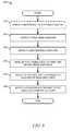
- FIG. 3is a flowchart illustrating a method for determining the deformation of a flexible display, according to an example embodiment.
- FIG. 4A-Bis a block diagram illustrating example bends and associated movement on a flexible display, according to an example embodiment.
- FIG. 5is a block diagram illustrating the movement of a bend across a flexible display, according to an example embodiment.
- FIG. 6is a flowchart illustrating a method of controlling a process through the detection of bend movement across a flexible display, according to an example embodiment.
- FIG. 7is a flowchart illustrating a method of controlling a process through the detection of bend movement across a flexible display, according to an example embodiment.
- FIG. 8is a flowchart illustrating a method of controlling a process through the detection of multiple bend gestures on a flexible display, according to an example embodiment.
- FIG. 9is a block diagram illustrating a computing platform suitable for use in certain example embodiments of the present technology.
- deforming a flexible display(such as by bending, twisting, or otherwise changing the shape from the default shape of the flexible display device) can produce signals indicative of specific deformations. Further, it has been discovered that movement of the deformations across the surface of the flexible display can be detected and tracked. The combination of deformation detection and deformation movements can be used to invoke or modify processes running on a computing device. For example, it has been discovered that deforming a flexible display so that a bend moves from one side of the display to the other can be distinguished from other specific movements of bends or twists, such that a specific user interface operation can be associated with individual bend movements or combinations of bend movements.
- moving a bend from left to right across a flexible displaycan cause a page to be turned within an e-reader application (process) running on a computing device.
- moving a bend from the bottom of a flexible display to the topcan cause a document to scroll a similar amount within a word processing application running on a computing device.
- the speed or direction of the bend or deformation movementcan be detected and used to alter the associated process modification. For example, in the scrolling examples, if the bend movement is fast, the amount of scroll applied to the document can be increased proportionally.
- moving a deformation diagonally across a flexible displaycan control zoom within an image processing application running on a computing device. In the image processing example, deformation movement up and to the left (relative to the display) can cause the image to be enlarged. Alternatively, deformation movement down and to the right can cause the image size to be reduced.
- a flexible or deformable displayis any device, capable of displaying computer generated graphics or text, that can be bent or deformed by a user. Deformations can include bending, folding, rolling, or any other non-destructive change in the shape of the surface of the display device. The deformations of a flexible display discussed within this document are not intended to include the minute deformation that may occur during use of a typical touch screen type display device (e.g., deformation caused by pushing a finger against a touch screen display).
- BendFor the purposes of this specification, to bend an item (e.g., a display panel) is to change the shape of the item so that it is no longer substantially straight or flat. Alternatively, a bend can represent some form of deformation from a resting or original state of a non-planar display. A bend in an item defines a localized change in the normal or original shape. A bend, for the purposes of this specification, has a location defined by the apex of the change in shape (or deformation). Additionally, for the purposes of this specification, a bend has an axis that includes an angle of orientation relative to the flexible display device.
- TwistFor the purposes of this specification, to twist an item (e.g., a flexible display panel) is to change the shape of the item by bending it is two different directions at substantially the same time.
- an iteme.g., a flexible display panel
- a bend gestureis a bend or twist deformation induced on a flexible display combined with movement of the bend or twist deformation across the flexible display. Bend gestures can be used to modify, activate, or cancel a process, among other things.
- a process when discussed in terms of a process running on a computerized devicerefers to an operating system depend resource allocation to execute program code.
- a processcan define memory space and reference identification for running a segment of code to perform a specific function on a particular device.
- the term processmay also be used within the specification to describe a sequence of operations performed manually or within a computerized system.
- the operationsmay be programming code executed by one or more processors, firmware programmed into a programmable hardware device to perform a series of operations, or a hardware device designed to perform a series of operations.
- FIG. 1is a block diagram illustrating a computing system 100 including a flexible display, according to an example embodiment.
- the computing system 100can include flexible display device 105 communicatively coupled to computing device 130 via interface 125 .
- display device 105may be a component of another device or system, such as a smart phone, mobile phone, portable computer (such as a laptop or notebook computer), computing tablet, remote control, reading device or other portable electronic device (represented here by computing system 100 ).
- Display device 105is a deformable display device. Although the default shape 115 of display device 105 can be substantially planar, display device 105 can be bendable or deformable to provide for bending or contouring 120 of the display. Deformation of the display device 105 can be performed by any agent (for example, by actions of a person or by mechanical action such as by a machine, or by a combination thereof).
- the display device 105can be coupled to the computing device 130 to receive image data, such as over an interface 140 .
- the image data received over interface 140can be analog or digital, for example, but are not limited to component video, digital visual interface (DVI), video graphics array (VGA) or high-definition multimedia interface (HDMI) video control signals.
- the display device 105can also be coupled to the computing device 130 , such as over an interface 145 , to provide deformation signals to the computing device 130 . Examples of the deformation signals sent over interface 145 are discussed further below in reference to FIG. 2 .
- the computing device 130can include a bend detection module 132 , a process modification module 134 , and a bend (or deformation) information memory device 136 .
- the bend detection module 132can receive the deformation signals from the flexible display device 105 .
- the bend detection module 132can analyze the deformation signals to determine bend or deformation locations and any movement associated with a particular bend or deformation.
- the bend detection module 132can store bend information within the bend information memory device 136 .
- the bend informationcan include data representing each detected deformation within the flexible display device 105 .
- the bend informationcan also incorporate movement information associated with each detected deformation.
- the bend detection module 132can track the apex of a bend, if the apex is detected as moving beyond a pre-defined distance from its originally detected location, the bend detection module 132 can indicate a bend movement. Bend movements may also be detected when a first bend is followed closely in time by a second bend, where the two bends have a pre-defined association.
- the process modification module 134can use information regarding deformations and associated movements of the deformations to modify processes (e.g., applications, threads, and the like) running on the computing device 130 .
- the process modification module 134receives deformation data directly from the bend detection module 132 .
- the process modification module 134can obtain deformation data stored in the bend information memory device 136 .
- the process modification module 134analyzes the bend (or deformation) data to select from a set of pre-defined control patterns.
- the control patternscan include one or more commands to be issued by system level processes running on the computing device 130 . These system level processes can issue commands that modify other processes operating within the computing device 130 .
- the computing device 130can include a user interface control sub-system (not shown in FIG. 1 ) that can issue user interface related commands to applications running on the computing device 130 .
- FIG. 2is a block diagram of a flexible display device 105 illustrating circuits 210 to detect bends or other deformations, according to an example embodiment.
- the circuits 210 within the flexible display device 105can include bend sensors 205 (also referred to in certain examples as load cells 205 ).
- the bend or deformation properties or characteristics of display device 105can be obtained using one or more deformation detection devices, for example, taking the form of load cells 205 mounted on or integrated within display device 105 .
- a deformation detection deviceproduces or generates one or more deformation detection signals as a function of the deformation of the deformable display device 105 .
- the deformation detection signalsare indicative of the deformation (or the deformation properties) of the deformable display device (e.g., where a deformation is and the degree thereof).
- An example of a deformation detection devicemay take the form of load cells 50 mounted or integrated with display device 105 .
- load cells 205are bonded onto display device 105 such that bending of the display device 105 produces corresponding analog (or, in an alternate embodiment, digital) electrical load cell signals 215 , serving as deformation detection signals, in one or more of the load cells 205 .
- the signals 215 generated from load cells 205can be proportional to the amount of bend in the display device 105 ; in other words, the signals 215 are generated from load cells 205 in response to (or as a function of) a deformation in the display device 105 .
- the signals 215can convey information about where deformations occur in the display device 105 , what kind of deformations they are (e.g., concave or convex), the degree of the deformations, and the movement of the deformation (bend) across the surface of the display device 105 .
- the signals from load cells 205can be conveyed on signal paths, such as circuits 210 , to the computing device 130 taking, for example, the form of a programmable computer or other electronic device capable of interpreting the signals to modify a process running or the computing device 130 or to generate display deformation data.
- the signals 215are analog signals, they are converted to digital data and processed in the computing device 130 to determine the location and relative motion of bends in the display device 105 .
- separate analog to digital circuitsmay be employed to digitize the signals 215 , if in analog form, prior to delivery to the computing device 130 .
- the concepts describedmay be applied in systems in which the deformation of the display device is monitored by apparatus external to the display device, and the signals 215 generated as a function of the deformation in the display device 105 are generated by a component other than the display device 105 itself.
- future flexible/deformable display devicesmay incorporate technology to produce signals similar in function to the signals 215 described above; such future display devices can be incorporated, for example, through reprogramming or replacement of the bend detection module 132 (illustrated in FIG. 1 ) within the computing device 130 .
- load cells 205can be oriented fully or partially transverse to one another in order that bends and contours in display device 105 can be ascertained from the signals 215 .
- the bend detection module 132can determine the approximate or exact deformation of display device 105 in three dimensions, and record bend or contour data representing the actual bends or contours in a storage device or memory on or off-board the computing device 130 (e.g., within the bend information memory device 136 ). Additionally, the bend detection module 132 (illustrated in FIG.
- the bend or contour of display device 105may be determined using other deformation detection devices or systems, such as from images of the display device captured from one or more cameras, where the images are processed in order to determine the deformation of the display device 105 . In such examples, multiple successive images can be captured and analyzed to determine movement of bends across a flexible display, such as display device 105 .
- FIG. 3is a flowchart illustrating a method for determining the deformation of a flexible display, according to an example embodiment.
- the depicted methodmay be embodied as a computer program 300 , illustrating an example computer program suitable for determining the deformation, resulting in bends or contours, of the flexible display device 105 .
- the computer program 300can be performed (e.g., executed) within the computer device 130 (illustrated in FIG. 1 ).
- load cell signals 215are received from load cells 205 .
- the program 300can continue at operation 320 with the computing device 130 determining the relative degree of strain or bend on the load cells 205 , which can be correlated to a bend or contour in the display device 105 .
- the computing device 130can use stored data indicative of the locations of each of load cells 205 on display device 105 , to assist in determining bend locations within the display device 105 .
- the computing device 130can also use a set of predetermined coefficients indicative of a correlation between load cell signals and respective physical display bending or deformation characteristics (i.e., coefficients selected expressly or inferentially prior to the reception of the load cell signals 215 ).
- the computer program 300can determine the relative bend in each section of display device 105 to create a data model that corresponds to or describes the physical deformation, such as bend or contour properties, or characteristics, of display device 105 .
- the deformation data model(also referred to a bend data model or simply bend information) can also include data associated with movement of the deformation (bend or contour) across the surface of the flexible display.
- the above operationsmay be executed one or more times. Repeated executions may be performed on a periodic basis, or may be performed upon detection of an event (such as a change in the load cell signals 215 ) or any combination thereof.
- computer program 300operates on a processing unit, such as that described with respect to FIG.
- the computer program discussed above, as well as any computer programs discussed herein,can be implemented within a hardware module such as on an application specific integrated circuit (ASIC), field-programmable gate array (FPGA), or similar programmable hardware device.
- ASICapplication specific integrated circuit
- FPGAfield-programmable gate array
- FIG. 4A-4Bare block diagrams illustrating example bends and associated movement across a flexible display 400 , according to an example embodiment.
- a flexible display 400is illustrated in FIG. 4 with a deformation (bend) 410 .
- the deformation 410can include an apex 412 and two edges ( 414 , 416 ). Note that the arrow depicted within FIG. 4 is indicating the direction of movement of deformation 410 , but is not actually part of the deformation.
- the apex 412 of the deformation 410can include an axis; in this example, the axis is running vertically across the flexible display 400 .
- the axiscould be said to be at zero or 180 degrees, relative to the user or a vertical orientation detected by the computing device 130 .
- the axiscan be in any angular orientation relative to the display.
- the angular orientationcan be represented as a number between zero and 180 degrees or between zero and 270 degrees, depending on whether there is any benefit in distinguishing between a 90 degree orientation and a 270 degree orientation.
- the example deformation in FIG. 4can include edges ( 414 , 416 ), which can be referred to as a leading edge (edge 416 ) and/or a trailing edge (edge 414 ).
- a leading or trailing edgecan be defined as a location where the localized deformation (bend) exceeds or transgresses a pre-defined threshold. Whether an edge is leading or trailing is determined based on the movement of the deformation, such as deformation 410 . In this example, because the deformation 410 is shown moving towards the left side of the flexible display 400 , the leading edge is represented by edge 416 and the trailing edge by edge 414 .
- FIG. 4Bdepicts a similar deformation 410 B with a horizontal axis (e.g., 90 degrees from vertical).
- FIG. 4Bcould be viewed as depicting the flexible display 400 rotated into a portrait orientation, with the deformation 410 B continuing to be in a relative orientation of zero or 180 degrees.
- the flexible display 400can include accelerometers or other mechanisms for indicating orientation. The signal from the accelerometer can be combined with the relative orientation of the deformation, such as deformation 410 B, by the computing device 130 and used to invoke a process modification on the computing device 130 .
- FIG. 5is a block diagram illustrating movement of a bend across a flexible display 500 , according to an example embodiment.
- a bendis illustrated moving from a first location 510 across the surface of the flexible display 500 to a second location 520 .
- This type of bend gesturea bend combined with movement of the bend, can be used to invoke various user-interface operations.
- the bend gesture illustrated in FIG. 5can be used to activate a text selection operation within a word processing application.
- the bend gesturecould be used to activate a page turn operation within an e-reader application.
- the bend gesturecan be used to activate an image manipulation operation, zoom in/out, rotate, within an image viewer or editor application.
- FIG. 6is a flowchart illustrating a method 600 of controlling a process through detection of bend movement across a flexible display, according to an example embodiment.
- the method 600can include operations such as detecting movement of a bend 610 and modifying a process 620 .
- the method 600can begin at operation 610 with the bend detection module 132 detecting movement of a bend across the surface of a flexible display, such as display device 105 .
- the method 600can continue at operation 620 with the process modification module 134 modifying a process running on computing device 130 based on the detected movement of a bend in the flexible display (e.g., display device 105 ).
- Modifying a processcan include generating user-interface commands that will be interpreted by application running on the computing device 130 .
- the method 600can be used to detect a user bending a flexible display, which is displaying an eBook, to invoke a page turn operation (e.g., modify the e-reader process by sending in a page turn command).
- the method 600can be used to detect a user bending a flexible display that is displaying a word processing application, at operation 610 , to invoke a text selection operation, at operation 620 .
- the usermay initiate a bend at a location on the flexible display associated with the start of the text to be selected. The user can then move the bend to select a segment of text in the displayed document, again at operation 620 .
- the usercan invoke a subsequent copy command by inducing a different bend or bend and movement combination, illustrated further in reference to FIG. 8 below.
- initiation of the bendcould occur in the area of a displayed object on the screen, such as an icon or line of text displayed on the screen, detected at operation 610 .
- Movement of the bendcan cause a corresponding movement of the object such that the object remains in the bend as the bend moves, processed in operation 620 .
- movement of the bend up or down the displaywould result in the corresponding movement of the line of text up or down the display in a scrolling fashion.
- Other text not in coincidence with the bendwould be correspondingly scrolled in conjunction with the movement of the bend.
- the speed of the movement detectedcan be translated into a corresponding scroll speed.
- the speed of the movementcan be translated into a magnitude associated with the scroll command.
- the direction of the movementcan be translated into a polarity associated with a user-interface command. For example, if the bend is detected moving in a vertically positive (upwards) direction a positive polarity can be associated with the selected command. If the user-interface command is a zoom command, a positive polarity indicates a zoom-in (e.g., enlarge) operation. Conversely, if the bend is detected moving in a vertically negative direction (downwards) a negative polarity can be associated with the user-interface command (e.g., zoom-out).
- Applications running on the computing device 130can interpret the user-interface commands resulting from the process modification operation 620 appropriately for the context of the application.
- FIG. 7is a flowchart illustrating a method 700 of controlling a process through detection of bend movement across a flexible display, according to an example embodiment.
- the method 700can include operations such as detecting a bend 710 , representing the bend in a bend information data structure 720 , detecting movement of the bend 730 , representing the bend movement in the bend information data structure 740 , analyzing the stored bend information 750 , and modifying a process 760 .
- the method 700can begin at operation 710 with the computing device 130 detecting a bend (deformation) in a flexible display, such as display device 105 .
- the bend detection operation 710can be accomplished by the bend detection module 132 processing the signals 215 received from the display device 105 over interface 145 .
- the method 700can continue with the computing device 130 representing the bend detected in the display device 105 in a bend information data structure.
- the bend information data structurecan be stored in the bend information memory device 136 and contains data representing a bend and associated movement of the bend.
- the data representing the bendcan include bend axis orientation, location, leading edge location, trailing edge location, and height, among other things.
- the bend movement informationcan include a speed, direction, and acceleration data.
- the movement informationcan be stored in a vector.
- the bend information data structurecan be stored in any memory device coupled to or embedded within computing device 130 .
- the method 700continues at operation 730 with the computing device 130 detecting movement of the bend across the display device 105 .
- the computing device 130can detect movement of a bend from a first area of the display device 105 to a second area of the display device 105 .
- the bend detection module 132rapidly samples signals 215 to facilitate detection of any indication of movement in a bend detected in the display device 105 .
- the display device 105can include a large number of bend (load or strain) sensors (e.g., a much denser array of sensors than depicted in FIG. 2 ) to assist in detecting minute movements in a deformation induced on a flexible display.
- the method 700can continue with the computing device 130 representing the bend movement information within the bend information data structure.
- the bend movement datais stored in association with a particular bend causing the movement.
- the bend detection module 132can interpret the bend movement data received from the display device 105 and store the movement data in memory, such as in the bend information memory device 136 .
- the bend movement information extracted by the bend detection module 132can include movement direction, speed, and acceleration (or deceleration) data.
- the bend movement informationcan also include bend magnitude or shape information. For example, if the curvature of the bend is changing (smaller or larger) this information can also be extracted by the bend detection module 132 and be stored for future processing.
- the method 700can continue with the computing device 130 analyzing the bend information (e.g., bend location and movement information) to select a control pattern.
- control patternscan be developed to match bend information profiles with process modifications.
- a bend information profilecan include initial location and orientation of a bend coupled with subsequent movement information (e.g., direction, speed, acceleration). Bend information profiles can be viewed as describing a deformation or bend gesture (e.g., a particular bend and movement combination).
- the method 700can conclude at operation 760 with the computing device 130 modifying a process in response to the selected control pattern.
- the process modification module 134can analyze the bend information to determine an appropriate process modification.
- bend gesturescan be used to launch new processes (e.g., applications), close processes, or initiate an application specific command, among other things.
- FIG. 8is a flowchart illustrating a method of controlling a process through detection of multiple bend gestures on a flexible display, according to an example embodiment.
- the computing device 130can invoke process modifications based on a series of two or more bend gestures performed in sequence.
- the method 800can include operations such as detecting a first bend gesture ( 820 ), detecting a second bend gesture ( 830 ), analyzing the combination of bend gestures ( 840 ), selecting a control pattern ( 850 ), and modifying a process ( 860 ).
- the method 700can also include an operation for detecting orientation of the display device ( 810 ). This optional operation is shown at the beginning of method 800 , but it could be performed any time prior to analyzing the bend gestures at operation 840 .
- the method 800begins at operation 820 with the computing device 130 detecting a first bend gesture from signals 215 received from the display device 105 .
- the method 800can continue with the computing device 130 detecting a second bend gesture from signals 215 received from the display device 105 .
- the bend gesturescan be detected by the bend detection module 132 within the computing device 130 .
- the method 800can continue with the computing device 130 analyzing the combination of first and second bend gestures applied to the display device 105 .
- the process modification module 134extracts data representing the bend gestures, stored in the bend information memory device 136 , to analyze the bend gestures.
- the method 800can continue with the computing device 130 selecting a control pattern based on analysis of the bend gestures.
- the method 800can conclude with the computing device 130 modifying a process in response to the selected control pattern. Note that in certain examples, the computing device 130 can modify a process based on identification of a certain bend gesture or combination of bend gestures without selection of a control pattern. In these examples, look-up tables or similar database mechanisms can be used to facilitate determining an appropriate process modification.
- FIG. 9is a block diagram illustrating a computing platform suitable for use in certain example embodiments of the present technology.
- the mobile device 900includes a processing unit 902 , memory 904 , removable storage 912 , non-removable storage 914 , display 922 , and display controller 928 .
- the processing unit 902may include one or more processing units or may include one or more multiple-core processing units.
- Memory 904may include volatile memory 906 and non-volatile memory 908 .
- Mobile device 900may include a variety of device-readable media, such as volatile memory 906 and non-volatile memory 908 , removable storage 912 and non-removable storage 914 .
- the storagemay include random access memory (RAM), read-only memory (ROM), erasable programmable read-only memory (EPROM) and electrically erasable programmable read-only memory (EEPROM), flash memory or other memory technologies, or any other medium capable of storing machine-readable instructions and data that may be present in a mobile electronic device.
- Mobile device 900may include input 916 , output 918 , and a communication connection device 920 .
- the display 922 included within the mobile device 900can be a flexible display capable of producing signals suitable for use within the methods described herein.
- the display 922communicates with the display controller 928 , which can control the images displayed on the display 922 .
- the display controller 928can also perform functions similar to those described in reference to the bend detection module 132 .
- the display controller 928can receive and distribute signals 215 for subsequent processing within the processing unit 902 .
- the mobile device 900typically operates in a networked environment using the communication connection device 920 to connect to one or more networks, such as a wireless telephone network.
- the mobile device 900may connect to one or more remote computers.
- the remote computermay include a personal computer (PC), server, router, network PC, a peer device, or other common network input, or the like.
- the communication connection device 920may connect to various network types that may include a wireless telephone network, a Local Area Network (LAN), a Wide Area Network (WAN), the Internet, a proprietary subscription-based network, or other networks.
- the mobile device 900also may include wireless telephone capabilities to provide voice telephone service via a wireless telephone network.
- Machine-readable instructions stored on a machine-readable mediumare executable by the processing unit 902 of the mobile device 900 .
- the memory 904 , removable storage 912 , and non-removable storage 914are examples of articles including a non-transitory machine-readable storage medium.
- a program with instructionsthat may be stored in memory 904 and when executed by the processing unit 902 can cause the mobile device 900 to perform one or more of the methods described herein.
- Other programsmay also be stored on a machine-readable medium, such as a browser application providing web browsing functionality for the mobile device 900 .
- Method examples described hereincan be machine or computer-implemented, at least in part. Some examples can include a computer-readable medium or machine-readable medium encoded with instructions operable to configure an electronic device to perform methods as described in the above examples.
- An implementation of such methodscan include code, such as microcode, assembly language code, a higher-level language code, or the like. Such code can include computer-readable instructions for performing various methods. The code may form portions of computer program products. Further, the code may be stored on one or more volatile or non-volatile computer-readable media during execution or at other times.
- These computer-readable mediamay include, but are not limited to, hard disks, removable magnetic disks, removable optical disks (e.g., compact disks and digital video disks), magnetic cassettes, memory cards or sticks, random access memories (RAMs), read-only memories (ROMs), and the like.
- the terms “a” or “an”are used, as is common in patent documents, to include one or more than one, independent of any other instances or usages of “at least one” or “one or more.”
- the term “or”is used to refer to a nonexclusive or, such that “A or B” includes “A but not B,” “B but not A,” and “A and B,” unless otherwise indicated.
Landscapes
- Engineering & Computer Science (AREA)
- Computer Hardware Design (AREA)
- Theoretical Computer Science (AREA)
- Human Computer Interaction (AREA)
- Physics & Mathematics (AREA)
- General Engineering & Computer Science (AREA)
- General Physics & Mathematics (AREA)
- User Interface Of Digital Computer (AREA)
Abstract
Description
Claims (13)
Priority Applications (1)
| Application Number | Priority Date | Filing Date | Title |
|---|---|---|---|
| US13/273,717US9007300B2 (en) | 2011-10-14 | 2011-10-14 | Method and system to control a process with bend movements |
Applications Claiming Priority (1)
| Application Number | Priority Date | Filing Date | Title |
|---|---|---|---|
| US13/273,717US9007300B2 (en) | 2011-10-14 | 2011-10-14 | Method and system to control a process with bend movements |
Publications (2)
| Publication Number | Publication Date |
|---|---|
| US20130093660A1 US20130093660A1 (en) | 2013-04-18 |
| US9007300B2true US9007300B2 (en) | 2015-04-14 |
Family
ID=48085650
Family Applications (1)
| Application Number | Title | Priority Date | Filing Date |
|---|---|---|---|
| US13/273,717Active2032-04-16US9007300B2 (en) | 2011-10-14 | 2011-10-14 | Method and system to control a process with bend movements |
Country Status (1)
| Country | Link |
|---|---|
| US (1) | US9007300B2 (en) |
Cited By (3)
| Publication number | Priority date | Publication date | Assignee | Title |
|---|---|---|---|---|
| US20160086527A1 (en)* | 2014-09-18 | 2016-03-24 | Samsung Display Co., Ltd. | Testing apparatus for testing display apparatus and method of testing the same |
| US20160098132A1 (en)* | 2014-10-07 | 2016-04-07 | Samsung Electronics Co., Ltd. | Electronic device including flexible display |
| US20200363900A1 (en)* | 2011-09-30 | 2020-11-19 | Apple Inc. | Flexible Electronic Devices |
Families Citing this family (39)
| Publication number | Priority date | Publication date | Assignee | Title |
|---|---|---|---|---|
| WO2010041227A1 (en)* | 2008-10-12 | 2010-04-15 | Barit, Efrat | Flexible devices and related methods of use |
| US9411423B2 (en)* | 2012-02-08 | 2016-08-09 | Immersion Corporation | Method and apparatus for haptic flex gesturing |
| US9767605B2 (en) | 2012-02-24 | 2017-09-19 | Nokia Technologies Oy | Method and apparatus for presenting multi-dimensional representations of an image dependent upon the shape of a display |
| US9804734B2 (en)* | 2012-02-24 | 2017-10-31 | Nokia Technologies Oy | Method, apparatus and computer program for displaying content |
| KR101661526B1 (en)* | 2012-04-08 | 2016-10-04 | 삼성전자주식회사 | Flexible display apparatus and user interface providing method thereof |
| KR101692252B1 (en)* | 2012-04-08 | 2017-01-04 | 삼성전자주식회사 | Flexible display apparatus and control method thereof |
| JP2013225052A (en) | 2012-04-23 | 2013-10-31 | Sony Corp | Display device |
| KR101864620B1 (en)* | 2012-05-09 | 2018-06-07 | 엘지전자 주식회사 | Mobile terminal and control method for the mobile terminal |
| KR20240045365A (en) | 2012-05-11 | 2024-04-05 | 가부시키가이샤 한도오따이 에네루기 켄큐쇼 | Electronic device, storage medium, program, and displaying method |
| KR20140004863A (en)* | 2012-07-03 | 2014-01-14 | 삼성전자주식회사 | Display method and apparatus in terminal having flexible display panel |
| KR102028175B1 (en)* | 2012-07-30 | 2019-10-04 | 삼성전자주식회사 | Flexible device for providing bending interaction guide and control method thereof |
| KR102042211B1 (en)* | 2012-08-20 | 2019-11-07 | 삼성전자주식회사 | Apparatas and method for changing display an object of bending state in an electronic device |
| KR101915064B1 (en)* | 2012-08-23 | 2018-11-05 | 삼성전자주식회사 | Flexible device and operating methods thereof |
| KR102028717B1 (en)* | 2012-09-18 | 2019-10-07 | 삼성전자주식회사 | Flexible apparatus and control method thereof |
| KR102145533B1 (en)* | 2012-10-04 | 2020-08-18 | 삼성전자주식회사 | Flexible display apparatus and control method thereof |
| KR20140044227A (en)* | 2012-10-04 | 2014-04-14 | 삼성전자주식회사 | Flexible display apparatus and control method thereof |
| JP5957619B2 (en)* | 2013-01-04 | 2016-07-27 | ノキア テクノロジーズ オーユー | Device shape change sensing method and apparatus |
| KR102056898B1 (en) | 2013-01-22 | 2019-12-18 | 삼성디스플레이 주식회사 | Flexible display and method for measuring angle of the same |
| KR102256677B1 (en)* | 2013-12-02 | 2021-05-28 | 삼성디스플레이 주식회사 | Flexible display apparatus and image displaying method of the same |
| WO2015121763A2 (en)* | 2014-02-13 | 2015-08-20 | Semiconductor Energy Laboratory Co., Ltd. | Display panel and data processing device |
| CN104951050B (en)* | 2014-03-24 | 2019-01-15 | 联想(北京)有限公司 | A kind of method and electronic equipment of controlling electronic devices |
| CN103854571B (en)* | 2014-03-26 | 2016-04-20 | 冠捷显示科技(厦门)有限公司 | A kind of method of intelligent curved-surface display equipment and adjustment curvature |
| CN105678684B (en)* | 2014-11-18 | 2020-11-03 | 中兴通讯股份有限公司 | Method and device for intercepting image |
| KR20160085202A (en)* | 2015-01-07 | 2016-07-15 | 삼성전자주식회사 | Display apparatus |
| KR102319684B1 (en)* | 2015-06-22 | 2021-11-02 | 엘지전자 주식회사 | Deformable display device and operating method thereof |
| US10712821B2 (en) | 2015-08-19 | 2020-07-14 | International Business Machines Corporation | Tactile graphical display |
| US10013060B2 (en) | 2015-09-18 | 2018-07-03 | Immersion Corporation | Systems and methods for providing haptic effects in response to deformation of a cover for an electronic device |
| WO2017054114A1 (en)* | 2015-09-28 | 2017-04-06 | 神画科技(深圳)有限公司 | Display system and display method therefor |
| CN107656666B (en)* | 2016-07-26 | 2020-09-25 | 北京小米移动软件有限公司 | Mobile terminal and scrolling speed determination method |
| CN107995961B (en)* | 2016-12-29 | 2020-10-27 | 深圳市柔宇科技有限公司 | Intelligent terminal and control method thereof |
| WO2018120139A1 (en)* | 2016-12-30 | 2018-07-05 | 深圳市柔宇科技有限公司 | Flexible display screen and display device |
| US10867535B2 (en)* | 2018-09-25 | 2020-12-15 | Rovi Guides, Inc. | Systems and methods for selecting a region of a flexible screen and controlling video playback |
| US10635288B2 (en)* | 2018-09-25 | 2020-04-28 | Rovi Guides, Inc. | Systems and methods for selecting a region of a flexible screen and controlling video playback |
| US11561683B2 (en) | 2018-09-25 | 2023-01-24 | Rovi Guides, Inc. | Systems and methods for selecting a region of a flexible screen and controlling video playback |
| CN117908733A (en)* | 2018-09-30 | 2024-04-19 | 华为技术有限公司 | Display control method of system navigation bar, graphical user interface and electronic equipment |
| EP3969980B1 (en)* | 2019-08-07 | 2024-04-24 | Samsung Electronics Co., Ltd. | Method and bendable device for constructing 3d data item |
| CN112416190B (en)* | 2019-08-23 | 2022-05-06 | 珠海金山办公软件有限公司 | A method and device for displaying documents |
| US11164495B1 (en)* | 2020-07-31 | 2021-11-02 | Ronnie Devon Stinson | Field-programmable mounted display apparatus |
| CN114120840B (en)* | 2021-12-11 | 2023-05-09 | 武汉华星光电半导体显示技术有限公司 | Deformation control method and deformation control device of flexible display panel |
Citations (32)
| Publication number | Priority date | Publication date | Assignee | Title |
|---|---|---|---|---|
| US6243075B1 (en) | 1997-08-29 | 2001-06-05 | Xerox Corporation | Graspable device manipulation for controlling a computer display |
| US20040008191A1 (en) | 2002-06-14 | 2004-01-15 | Ivan Poupyrev | User interface apparatus and portable information apparatus |
| US6943773B2 (en) | 2001-05-11 | 2005-09-13 | Palmone, Inc. | Page flicking mechanism for electronic display devices that paginate content |
| US7109967B2 (en) | 2002-03-29 | 2006-09-19 | Kabushiki Kaisha Toshiba | Display input device and display input system |
| US20060238494A1 (en) | 2005-04-22 | 2006-10-26 | International Business Machines Corporation | Flexible displays as an input device |
| US20070247422A1 (en) | 2006-03-30 | 2007-10-25 | Xuuk, Inc. | Interaction techniques for flexible displays |
| US7298365B2 (en) | 2003-03-31 | 2007-11-20 | Canon Kabushiki Kaisha | Information device |
| US7342569B2 (en) | 2001-09-13 | 2008-03-11 | E-Book Systems Pte Ltd. | Method for flipping pages via electromechanical information browsing device |
| EP1967937A1 (en) | 2007-03-06 | 2008-09-10 | Polymer Vision Limited | A display unit, a method and a computer program product |
| US7443380B2 (en) | 2003-12-11 | 2008-10-28 | Canon Kabushiki Kaisha | Display apparatus |
| WO2008150600A1 (en) | 2007-06-05 | 2008-12-11 | Immersion Corporation | Method and apparatus for haptic enabled flexible touch sensitive surface |
| US20090120696A1 (en)* | 2007-06-13 | 2009-05-14 | Tokai Rubber Industries, Ltd. | Deformable sensor system |
| GB2456512A (en) | 2008-01-15 | 2009-07-22 | Hewlett Packard Development Co | Apparatus for changing display content based on a detected change in curvature of the display surface |
| WO2010004080A1 (en) | 2008-07-10 | 2010-01-14 | Nokia Corporation | User interface, device and method for a physically flexible device |
| US7652819B2 (en)* | 2007-04-12 | 2010-01-26 | Mitsubishi Electric Corporation | Projection-type image display apparatus |
| EP2150031A1 (en) | 2008-07-29 | 2010-02-03 | LG Electronics Inc. | Mobile terminal including a flexible display and operation control method thereof |
| US20100029335A1 (en)* | 2008-08-04 | 2010-02-04 | Harry Vartanian | Apparatus and method for communicating multimedia documents or content over a wireless network to a digital periodical or advertising device |
| US20100053076A1 (en) | 2008-08-29 | 2010-03-04 | Searete Llc | Display control based on bendable interface containing electronic device conformation sequence status |
| US20100053074A1 (en) | 2008-08-29 | 2010-03-04 | Searete Llc, A Limited Liability Corporation Of The State Of Delaware | Display control based on bendable display containing electronic device conformation sequence status |
| US20100053075A1 (en) | 2008-08-29 | 2010-03-04 | Searete Llc | Display control based on bendable interface containing electronic device conformation sequence status |
| US20100053073A1 (en) | 2008-08-29 | 2010-03-04 | Searete Llc, A Limited Liability Corporation Of The State Of Delaware | Display control based on bendable display containing electronic device conformation sequence status |
| US20100066685A1 (en) | 2006-06-12 | 2010-03-18 | Plastic Logic Limited | Electronic document reading device |
| US20100085301A1 (en) | 2008-08-29 | 2010-04-08 | Searete Llc, A Limited Liability Corporation Of The State Of Delaware | Bendable electronic interface external control system and method |
| WO2010041227A1 (en) | 2008-10-12 | 2010-04-15 | Barit, Efrat | Flexible devices and related methods of use |
| US20100103123A1 (en) | 2008-08-29 | 2010-04-29 | Searete Llc, A Limited Liability Corporation Of The State Of Delaware | Bendable electronic device status information system and method |
| US20100117954A1 (en) | 2008-11-07 | 2010-05-13 | Searete Llc, A Limited Liability Corporation Of The State Of Delaware | E-paper display control based on conformation sequence status |
| US20100117955A1 (en) | 2008-08-29 | 2010-05-13 | Searete Llc, A Limited Liability Corporation Of The State Of Delaware | E-paper display control based on conformation sequence status |
| US20100120470A1 (en) | 2008-11-10 | 2010-05-13 | Jong Hwan Kim | Mobile terminal using flexible display and method of controlling the mobile terminal |
| US20100124879A1 (en) | 2008-11-14 | 2010-05-20 | Searete Llc. | E-paper external control system and method |
| US20100141605A1 (en) | 2008-12-08 | 2010-06-10 | Samsung Electronics Co., Ltd. | Flexible display device and data displaying method thereof |
| EP2202624A2 (en) | 2008-12-26 | 2010-06-30 | Sony Corporation | Display device |
| US8009421B2 (en)* | 2006-12-20 | 2011-08-30 | Fujifilm Corporation | Display element, portable equipment and imaging device |
- 2011
- 2011-10-14USUS13/273,717patent/US9007300B2/enactiveActive
Patent Citations (39)
| Publication number | Priority date | Publication date | Assignee | Title |
|---|---|---|---|---|
| US6243075B1 (en) | 1997-08-29 | 2001-06-05 | Xerox Corporation | Graspable device manipulation for controlling a computer display |
| US6943773B2 (en) | 2001-05-11 | 2005-09-13 | Palmone, Inc. | Page flicking mechanism for electronic display devices that paginate content |
| US7394452B2 (en) | 2001-05-11 | 2008-07-01 | Palm, Inc. | Computing device for displaying content in pages or in sequence |
| US7342569B2 (en) | 2001-09-13 | 2008-03-11 | E-Book Systems Pte Ltd. | Method for flipping pages via electromechanical information browsing device |
| US7109967B2 (en) | 2002-03-29 | 2006-09-19 | Kabushiki Kaisha Toshiba | Display input device and display input system |
| US20060274036A1 (en) | 2002-03-29 | 2006-12-07 | Kabushiki Kaisha Toshiba | Display input device and display input system |
| US20040008191A1 (en) | 2002-06-14 | 2004-01-15 | Ivan Poupyrev | User interface apparatus and portable information apparatus |
| US7298365B2 (en) | 2003-03-31 | 2007-11-20 | Canon Kabushiki Kaisha | Information device |
| US7443380B2 (en) | 2003-12-11 | 2008-10-28 | Canon Kabushiki Kaisha | Display apparatus |
| US20060238494A1 (en) | 2005-04-22 | 2006-10-26 | International Business Machines Corporation | Flexible displays as an input device |
| US20070247422A1 (en) | 2006-03-30 | 2007-10-25 | Xuuk, Inc. | Interaction techniques for flexible displays |
| US20100066685A1 (en) | 2006-06-12 | 2010-03-18 | Plastic Logic Limited | Electronic document reading device |
| US8009421B2 (en)* | 2006-12-20 | 2011-08-30 | Fujifilm Corporation | Display element, portable equipment and imaging device |
| EP1967937A1 (en) | 2007-03-06 | 2008-09-10 | Polymer Vision Limited | A display unit, a method and a computer program product |
| WO2008108645A1 (en) | 2007-03-06 | 2008-09-12 | Polymer Vision Limited | A display unit, a method and a computer program product |
| US20100164973A1 (en) | 2007-03-06 | 2010-07-01 | Polymer Vision Ltd. | Display unit, a method and a computer program product |
| US7652819B2 (en)* | 2007-04-12 | 2010-01-26 | Mitsubishi Electric Corporation | Projection-type image display apparatus |
| WO2008150600A1 (en) | 2007-06-05 | 2008-12-11 | Immersion Corporation | Method and apparatus for haptic enabled flexible touch sensitive surface |
| US20090120696A1 (en)* | 2007-06-13 | 2009-05-14 | Tokai Rubber Industries, Ltd. | Deformable sensor system |
| US8149211B2 (en)* | 2007-06-13 | 2012-04-03 | Tokai Rubber Industries, Ltd. | Deformable sensor system |
| GB2456512A (en) | 2008-01-15 | 2009-07-22 | Hewlett Packard Development Co | Apparatus for changing display content based on a detected change in curvature of the display surface |
| US20100011291A1 (en) | 2008-07-10 | 2010-01-14 | Nokia Corporation | User interface, device and method for a physically flexible device |
| WO2010004080A1 (en) | 2008-07-10 | 2010-01-14 | Nokia Corporation | User interface, device and method for a physically flexible device |
| EP2150031A1 (en) | 2008-07-29 | 2010-02-03 | LG Electronics Inc. | Mobile terminal including a flexible display and operation control method thereof |
| US8082003B2 (en)* | 2008-07-29 | 2011-12-20 | Lg Electronics Inc. | Mobile terminal and operation control method thereof |
| US20100029335A1 (en)* | 2008-08-04 | 2010-02-04 | Harry Vartanian | Apparatus and method for communicating multimedia documents or content over a wireless network to a digital periodical or advertising device |
| US20100053076A1 (en) | 2008-08-29 | 2010-03-04 | Searete Llc | Display control based on bendable interface containing electronic device conformation sequence status |
| US20100053074A1 (en) | 2008-08-29 | 2010-03-04 | Searete Llc, A Limited Liability Corporation Of The State Of Delaware | Display control based on bendable display containing electronic device conformation sequence status |
| US20100053075A1 (en) | 2008-08-29 | 2010-03-04 | Searete Llc | Display control based on bendable interface containing electronic device conformation sequence status |
| US20100053073A1 (en) | 2008-08-29 | 2010-03-04 | Searete Llc, A Limited Liability Corporation Of The State Of Delaware | Display control based on bendable display containing electronic device conformation sequence status |
| US20100085301A1 (en) | 2008-08-29 | 2010-04-08 | Searete Llc, A Limited Liability Corporation Of The State Of Delaware | Bendable electronic interface external control system and method |
| US20100103123A1 (en) | 2008-08-29 | 2010-04-29 | Searete Llc, A Limited Liability Corporation Of The State Of Delaware | Bendable electronic device status information system and method |
| US20100117955A1 (en) | 2008-08-29 | 2010-05-13 | Searete Llc, A Limited Liability Corporation Of The State Of Delaware | E-paper display control based on conformation sequence status |
| WO2010041227A1 (en) | 2008-10-12 | 2010-04-15 | Barit, Efrat | Flexible devices and related methods of use |
| US20100117954A1 (en) | 2008-11-07 | 2010-05-13 | Searete Llc, A Limited Liability Corporation Of The State Of Delaware | E-paper display control based on conformation sequence status |
| US20100120470A1 (en) | 2008-11-10 | 2010-05-13 | Jong Hwan Kim | Mobile terminal using flexible display and method of controlling the mobile terminal |
| US20100124879A1 (en) | 2008-11-14 | 2010-05-20 | Searete Llc. | E-paper external control system and method |
| US20100141605A1 (en) | 2008-12-08 | 2010-06-10 | Samsung Electronics Co., Ltd. | Flexible display device and data displaying method thereof |
| EP2202624A2 (en) | 2008-12-26 | 2010-06-30 | Sony Corporation | Display device |
Non-Patent Citations (17)
| Title |
|---|
| "Canadian Application Serial No. 2,792,253, Office Action mailed May 21, 2014", 3 pgs. |
| "Cobra: Flexible Displays for Mobile Gaming Scenarios", [Online]. Retrieved from the Internet: , 5 pgs. |
| "Cobra: Flexible Displays for Mobile Gaming Scenarios", [Online]. Retrieved from the Internet: <URL: http://www.hml.queensu.ca/files/cobra.pdf>, 5 pgs. |
| "European Application Serial No. 11185329.7, Extended Search Report mailed Mar. 15, 2012", 13 pgs. |
| "European Application Serial No. 11185329.7, Response filed Oct. 5, 2012 to Search Report mailed Mar. 15, 2012", 14 pgs. |
| "Foldable User Interfaces and Origami Input Devices [Video]", [Online]. Retrieved from the Internet: , (Uploaded 2008), 3 min, 21 sec. |
| "Foldable User Interfaces and Origami Input Devices [Video]", [Online]. Retrieved from the Internet: <URL: http://www.youtube.com/watch?v=e6jJp-AWFFY>, (Uploaded 2008), 3 min, 21 sec. |
| "Queens University Human Media Lab", [Online]. Retrieved from the Internet: , 3 pgs. |
| "Queens University Human Media Lab", [Online]. Retrieved from the Internet: <URL: http://www.hml.queensu.ca>, 3 pgs. |
| "The Future of User Interfaces", [Online]. Retrieved from the Internet: , (Accessed on Jul. 14, 2011), 21 pgs. |
| "The Future of User Interfaces", [Online]. Retrieved from the Internet: <URL: Downloaded from http://sixrevisions.com/user-interface/the-future-of-user-interfaces/>, (Accessed on Jul. 14, 2011), 21 pgs. |
| (approximately: "Intuitive operation of a bendable display") [Video], [Online]. Retrieved from the Internet: , (Uploaded 2010), 25 seconds. |
| (approximately: "Intuitive operation of a bendable display") [Video], [Online]. Retrieved from the Internet: <URL: http://www.youtube.com/watch?v=NGDyxA4BPH4>, (Uploaded 2010), 25 seconds. |
| Dries, "Touch Affordances Workshop Outcome", Interact, [Online] Retrieved from the Internet: , (Sep. 4, 2009), 6 pgs. |
| Dries, "Touch Affordances Workshop Outcome", Interact, [Online] Retrieved from the Internet: <http://www.touchaffordances.org/?page—id=74>, (Sep. 4, 2009), 6 pgs. |
| Goyal, Nitesh, "COMET: Collaboration in Applications for Mobile Environments by Twisting", Interact, (2009), 1-6. |
| Lahey, Byron, et al., "PaperPhone: Understanding the Use of Band Gestures in Mobile Devices with Flexible Electronic Paper Displays", CHI Session: Flexible Grips & Gestures, (May 2011), 1303-1312. |
Cited By (9)
| Publication number | Priority date | Publication date | Assignee | Title |
|---|---|---|---|---|
| US20200363900A1 (en)* | 2011-09-30 | 2020-11-19 | Apple Inc. | Flexible Electronic Devices |
| US11675390B2 (en)* | 2011-09-30 | 2023-06-13 | Apple Inc. | Flexible electronic devices |
| US20230259163A1 (en)* | 2011-09-30 | 2023-08-17 | Apple Inc. | Flexible Electronic Devices |
| US11994906B2 (en)* | 2011-09-30 | 2024-05-28 | Apple Inc. | Flexible electronic devices |
| US20240288897A1 (en)* | 2011-09-30 | 2024-08-29 | Apple Inc. | Flexible Electronic Devices |
| US20160086527A1 (en)* | 2014-09-18 | 2016-03-24 | Samsung Display Co., Ltd. | Testing apparatus for testing display apparatus and method of testing the same |
| US9940859B2 (en)* | 2014-09-18 | 2018-04-10 | Samsung Display Co., Ltd. | Testing apparatus for testing display apparatus and method of testing the same |
| US20160098132A1 (en)* | 2014-10-07 | 2016-04-07 | Samsung Electronics Co., Ltd. | Electronic device including flexible display |
| US10108230B2 (en)* | 2014-10-07 | 2018-10-23 | Samsung Electronics Co., Ltd | Electronic device including flexible display |
Also Published As
| Publication number | Publication date |
|---|---|
| US20130093660A1 (en) | 2013-04-18 |
Similar Documents
| Publication | Publication Date | Title |
|---|---|---|
| US9007300B2 (en) | Method and system to control a process with bend movements | |
| CA2792253C (en) | Method and system to control a process with bend movements | |
| JP7595114B2 (en) | Crown Input for Wearable Electronics | |
| CN114467078B (en) | User interface adaptation based on inferred content occlusion and user intent | |
| US8552999B2 (en) | Control selection approximation | |
| US9489121B2 (en) | Optimal display and zoom of objects and text in a document | |
| US20160154564A1 (en) | Electronic device and method for providing desktop user interface | |
| CN101464773A (en) | Method and computer system for displaying program execution window according to user position | |
| US20140289672A1 (en) | Graph display apparatus, graph display method and storage medium having stored thereon graph display program | |
| US10139982B2 (en) | Window expansion method and associated electronic device | |
| CN108369486B (en) | Universal inking support | |
| US20200341607A1 (en) | Scrolling interface control for computer display | |
| US20120159319A1 (en) | Method for simulating a page turn in an electronic document | |
| CN101996046B (en) | Application program management system and method | |
| US20120032984A1 (en) | Data browsing systems and methods with at least one sensor, and computer program products thereof | |
| CN102376290B (en) | Data browsing system and method combined with sensors | |
| US20240184443A1 (en) | Display control method, electronic device, and readable storage medium | |
| CN118963581A (en) | Annotation method, device, equipment and storage medium based on large-screen device | |
| HK1180062B (en) | Control selection approximation | |
| HK1180062A (en) | Control selection approximation | |
| AU2014200702A1 (en) | Control selection approximation | |
| JP2013246481A (en) | Operation input device |
Legal Events
| Date | Code | Title | Description |
|---|---|---|---|
| AS | Assignment | Owner name:RESEARCH IN MOTION CORPORATION, DELAWARE Free format text:ASSIGNMENT OF ASSIGNORS INTEREST;ASSIGNORS:HIRSCH, ALEXANDER SAMSON;DELUCA, MICHAEL JOSEPH;SIGNING DATES FROM 20111110 TO 20120104;REEL/FRAME:027630/0971 | |
| AS | Assignment | Owner name:RESEARCH IN MOTION LIMITED, ONTARIO Free format text:ASSIGNMENT OF ASSIGNORS INTEREST;ASSIGNOR:RESEARCH IN MOTION CORPORATION;REEL/FRAME:028961/0654 Effective date:20120913 | |
| AS | Assignment | Owner name:BLACKBERRY LIMITED, ONTARIO Free format text:CHANGE OF NAME;ASSIGNOR:RESEARCH IN MOTION LIMITED;REEL/FRAME:034012/0007 Effective date:20130709 | |
| FEPP | Fee payment procedure | Free format text:PAYOR NUMBER ASSIGNED (ORIGINAL EVENT CODE: ASPN); ENTITY STATUS OF PATENT OWNER: LARGE ENTITY | |
| STCF | Information on status: patent grant | Free format text:PATENTED CASE | |
| MAFP | Maintenance fee payment | Free format text:PAYMENT OF MAINTENANCE FEE, 4TH YEAR, LARGE ENTITY (ORIGINAL EVENT CODE: M1551); ENTITY STATUS OF PATENT OWNER: LARGE ENTITY Year of fee payment:4 | |
| MAFP | Maintenance fee payment | Free format text:PAYMENT OF MAINTENANCE FEE, 8TH YEAR, LARGE ENTITY (ORIGINAL EVENT CODE: M1552); ENTITY STATUS OF PATENT OWNER: LARGE ENTITY Year of fee payment:8 | |
| AS | Assignment | Owner name:MALIKIE INNOVATIONS LIMITED, IRELAND Free format text:ASSIGNMENT OF ASSIGNORS INTEREST;ASSIGNOR:BLACKBERRY LIMITED;REEL/FRAME:064104/0103 Effective date:20230511 | |
| AS | Assignment | Owner name:MALIKIE INNOVATIONS LIMITED, IRELAND Free format text:NUNC PRO TUNC ASSIGNMENT;ASSIGNOR:BLACKBERRY LIMITED;REEL/FRAME:064270/0001 Effective date:20230511 |