US9007181B2 - Method and system for discovery and transparent status reporting for sensor networks - Google Patents
Method and system for discovery and transparent status reporting for sensor networksDownload PDFInfo
- Publication number
- US9007181B2 US9007181B2US12/684,402US68440210AUS9007181B2US 9007181 B2US9007181 B2US 9007181B2US 68440210 AUS68440210 AUS 68440210AUS 9007181 B2US9007181 B2US 9007181B2
- Authority
- US
- United States
- Prior art keywords
- wireless node
- response message
- node device
- sensor device
- sensor
- Prior art date
- Legal status (The legal status is an assumption and is not a legal conclusion. Google has not performed a legal analysis and makes no representation as to the accuracy of the status listed.)
- Active, expires
Links
Images


Classifications
- G—PHYSICS
- G08—SIGNALLING
- G08B—SIGNALLING OR CALLING SYSTEMS; ORDER TELEGRAPHS; ALARM SYSTEMS
- G08B13/00—Burglar, theft or intruder alarms
- G08B13/22—Electrical actuation
- G08B13/24—Electrical actuation by interference with electromagnetic field distribution
- G08B13/2402—Electronic Article Surveillance [EAS], i.e. systems using tags for detecting removal of a tagged item from a secure area, e.g. tags for detecting shoplifting
- G08B13/2451—Specific applications combined with EAS
- G08B13/2462—Asset location systems combined with EAS
- G—PHYSICS
- G06—COMPUTING OR CALCULATING; COUNTING
- G06K—GRAPHICAL DATA READING; PRESENTATION OF DATA; RECORD CARRIERS; HANDLING RECORD CARRIERS
- G06K7/00—Methods or arrangements for sensing record carriers, e.g. for reading patterns
- G06K7/10—Methods or arrangements for sensing record carriers, e.g. for reading patterns by electromagnetic radiation, e.g. optical sensing; by corpuscular radiation
- G06K7/10009—Methods or arrangements for sensing record carriers, e.g. for reading patterns by electromagnetic radiation, e.g. optical sensing; by corpuscular radiation sensing by radiation using wavelengths larger than 0.1 mm, e.g. radio-waves or microwaves
Definitions
- the present inventionrelates generally to network security systems and, in particular, to a method and system for transparently assessing and reporting the status of wireless nodes in the network security system.
- EAS systemsare used to protect articles from unauthorized removal from a protected area. Such systems typically operate using a sensor affixed to the article being protected. The sensors are arranged such that, when activated, the sensors respond to an interrogation signal in a predictable manner, thereby allowing the interrogating device, e.g., reader, to determine that an active sensor is in the interrogation zone. For example, an interrogation zone may be established near the exit of a store so that articles with activated sensors trigger an alarm when detected by the reader.
- EAS systemsincorporate a network controller that communicates with each sensor in the network.
- This communication link between the network controller and the sensorscan be either wired or wireless.
- sensors that normally operate in a wired environmentmay need to be utilized in a wireless environment. It is desired to utilize these sensors without burdensome or costly changes in design or processing.
- Sensors and their wireless node functionsmay be incorporated into one operational unit.
- the sensoris in communication with a wireless node in the network.
- the wireless node and the sensorcommunicate and manage the wireless functions. It is beneficial for the network controller to learn the status and overall health of wireless nodes within the network.
- current systemsrequire the sensors themselves to interface with wireless nodes and to determine the relative health and status of each wireless node it is in contact with and report back to the network controller.
- the sensoris burdened with the task of monitoring and reporting to the network controller the health of the wireless node and its functions.
- the present inventionadvantageously provides a method and system for providing the health and status of wireless node devices to a network controller in an electronic article surveillance system. This is accomplished by the wireless node devices appending their status information to a sensor device message that is transmitted to the network controller. The wireless node device status information is appended to the sensor device message without the sensor's knowledge. Thus, the health and status of the wireless node devices can be ascertained without that burden being placed on the sensor devices themselves.
- a method of monitoring wireless node devices in an electronic article surveillance (“EAS”) systemincludes polling at least one sensor device for status information.
- the at least one sensor deviceis in communication with at least one wireless node device.
- the methodalso includes receiving a response message from the at least one wireless node device where the response message contains sensor status information generated by the at least one sensor device and wireless node status information appended to the sensor status information by the at least one wireless node device.
- the methodalso includes extracting the wireless node status information from the response message, where the response message includes a frame transmission.
- the present inventionprovides a wireless node device for use in an EAS system.
- the wireless node deviceis in communication with at least one sensor device in which the wireless node device has a wireless transmitter.
- a receiveris arranged to receive a response message from the at least one sensor device.
- a processoris in communication with the receiver and the wireless transmitter. The processor operates to append wireless node device status information to the response message received from the at least one sensor device. The processor sends the response message with the appended wireless node device status information to the wireless transmitter.
- the present inventionprovides a method of supplying wireless node device status information from a wireless node device to a network controller in an electronic article surveillance (“EAS’) system. Communication is established with at least one sensor device. Wireless node device status information is appended to a response message received from the sensor device. The response message with the appended wireless node device status information is transmitted to the network controller.
- EASelectronic article surveillance
- FIG. 1is a block diagram of system constructed in accordance with the principles of the present invention
- FIG. 2is a block diagram showing the relationship between wireless node addresses, sensor device addresses and the network controller in accordance with the principles of the present invention
- FIG. 3is a diagram of an exemplary frame structure of a wireless frame transmission incorporating the principles of the present invention
- FIG. 4is a table of exemplary wireless node addresses and associated sensor device addresses constructed in accordance with the principles of the present invention.
- FIG. 5is a flowchart of an exemplary process performed by a network controller according to the principles of the present invention.
- relational termssuch as “first” and “second,” “top” and “bottom,” and the like, may be used solely to distinguish one entity or element from another entity or element without necessarily requiring or implying any physical or logical relationship or order between such entities or elements.
- One embodiment of the present inventionadvantageously provides a system and method for transparently assessing and reporting the status and health of wireless network nodes in an EAS system.
- the systemallows a network controller to obtain status information from a sensor device without the need for the controller to directly address any of the wireless nodes within the network and without the need for the sensor to be redesigned or burdened with the extra responsibility of reporting on the health of wireless nodes.
- the wireless nodeis situated between the network controller and the sensor devices' communication interface.
- the wireless nodeattaches its status information to a response message transmitted from the sensor device to the network controller in response to a status query. This can be done without altering the structure or design of the sensor device.
- the network controllerextracts the status information of the wireless node from the sensor device's response message.
- the network controllerconstructs a table listing addresses for each wireless access node and their corresponding sensor device addresses. In this fashion, the network controller can assess the health of each wireless node in the network either by directing a status command to the nodes' addresses or by processing status information that each wireless node appended to a response message from its corresponding sensor device.
- the wireless node information that is appendedis done so without the knowledge of the sensor thus providing, from the sensor's perspective, a transparent reporting system and method.
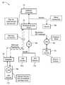
- FIG. 1a diagram of a network topology for an expanded star network of an electronic article surveillance (“EAS”) communication network 10 .
- Network 10includes one or more sensor devices 12 a - 12 d (four shown, referenced collectively as “sensor device 12 ”) and a local device manager (“LDM”) or network controller 14 .
- Sensor devices 12may be include any type of sensor such as, for example, a temperature sensor, or an EAS sensor.
- System 10may include a wireless access point 16 , which manages the network 10 and implements a poll-response protocol method to transfer information. Wireless access point 16 may be separate from network controller 14 or incorporated within network controller 14 as one unit.
- One or more repeaters 20are used to extend the range of the wireless access point 16 and to assist in the communication of messages between network controller 14 and sensor devices 12 .
- Messages routed through repeaters 20are routed according to a method established for a particular network 10 with the appropriate fields and controls.
- all messages detected by repeater 20are replayed, without altering the message's packet frame, in order to extend the range of network 10 .
- repeater informationis included in routing tables and control methods are implemented to reduce RF transmissions by repeater 20 .
- Wireless node device 18 a , 18 b , and 18 care also included in the network 10 and are in electronic communication with certain sensor devices 12 as well as network controller 14 via wireless access point 16 .
- network 10may include any number of wireless access points 16 , sensor devices 12 and wireless nodes devices 18 .
- Each wireless node device 18may include a power source, a transceiver, a micro-controller, external memory, sensors and an analog-to-digital convertor, along with other hardware and software enabling the wireless node device 18 to communicate with sensor devices 12 , wireless access point 16 , and network controller 14 .
- sensor devices 12receive polling request signals from controller 14 .
- sensor device 12is an electronic transmitter/responder.
- Sensor device 12can be a portable or mobile device, such as a hand-held device, or can be a device in a fixed-position/fixed-mount configuration such as a pedestal, depending upon the desired application.
- Sensor device 12responds to a transmitted or communicated polling request signal from the controller 14 .
- Sensor device 12such as an EAS system pedestal, can emit radio waves in an interrogation zone to interrogate tags within the interrogation zone, the zone size varying depending upon the power output and the frequency used.
- Sensor device 12can determine the status of an interrogated tag and pass corresponding data to a host computer for processing as part of a response to a polling request signal.
- Sensor devices 12can communicate with network controller 14 either via a wired network connection or wirelessly.
- Network controller 14controls the processing of information and the operation of the wireless access point 16 .
- Network controller 14manages network 10 by collecting, assessing and processing information related to the health and status of the network 10 .
- network controller 14ascertains the status and health of the wireless node devices 18 in the network. The present invention provides this information to network controller 14 in a way that is transparent to sensor devices 12 .
- sensor devices 12communicate with network controller 14 via wireless nodes 18 .
- Sensor devices 12 and wireless device nodes 18communicate with each other within network 10 .
- a wireless node device 18 eis embedded within or included within the same housing as a sensor device 12 d .
- more than one sensor device, e.g. 12 a and 12 bare in communication with a single wireless node device 18 a , as shown in FIG. 1 .
- the present inventionallows the health and status of each wireless node device 18 to be determined and transmitted to network controller 14 without burdening the sensor device 12 with this task.
- the present inventionallows wireless node device 18 to communicate its status to network controller 14 by appending, e.g., attaching or embedding, its device address and wireless status to message responses from a sensor device 12 it is in communication with.
- the information appendedis communicated to processing layers beyond the media access and control layer of the wireless access point 16 .
- sensor devices 12are unaware that additional status and information is being appended to their message response.
- the address of a wireless node device 18can be associated with the address of more than one sensor device address. This association allows network controller 14 to capture the network topology where multiple sensor devices 12 can be physically connected to one wireless node device 18 which services the wired network.
- network controller 14becomes aware of the presence of each wireless node device 18 in the network as well as learning which sensor device 12 is associated with which wireless node device 18 . This allows the network, via network controller 14 to “self-learn” the topology of the network.
- sensor device 12 areceives a status request from network controller 14 .
- the response sent to network controller 14also includes status information related to the health and status of wireless node device 18 a .
- Sensor device 12 a and wireless node device 18 aare in communication with each other such as, for example, via a wired RS-485 standard connection.
- Sensor devices 12receive inquiries from network controller 14 as to its current status.
- sensor devices 12may provide information regarding not only its relative health status but other sensor data as well. For example, if sensor device 12 is a pedestal, the pedestal may report if an alarm has occurred. If sensor device 12 is a deactivator, it can report how many deactivations have occurred.
- network controller 14wishes to obtain status information from wireless node devices that are associated with sensor device 12 a .
- Wireless node device 18 aappends its address and wireless status information to a response message sent from sensor device 12 a .
- wireless node device 18 acan also append its address and wireless status information to a response message sent from sensor device 12 b .
- wireless node device 18 eis embedded within sensor device 12 d and appends its wireless address and status within the response message from sensor device 12 d to network controller 14 .
- each sensor device 12is unaware that additional status and address information is being appended to its message. Messages exchanged between network controller 14 and sensor devices 12 can be transmitted directly or via repeater 20 .
- FIG. 2is a diagram showing how network controller 14 and wireless access point 16 receive status information from one or more wireless node devices 18 via the dual addressing method described above.
- wireless node device 18is in communication with one or more sensor devices 12 .
- Wireless node device 18appends information including its current status and health as well as its wireless node address in a transmission to sensor device 12 .
- the address of a wireless node device 18can be associated with the address of more than one sensor device address.
- the wireless node deviceis aware of the status information being transmitted by the sensor device 12 to network controller 14 by decoding the command field of the message that it is being transmitted by sensor device 12 to network controller 14 through the network.
- Wireless node device 18appends its status information and updates other fields in the sensor device frame transmission as needed. For example, the size of the sensor device frame may need to be increased to accommodate the added information that is being sent in the transmitted frame.
- network controller 14Upon receipt of sensor device transmissions, network controller 14 builds a table of wireless node device addresses and associated sensor device addresses. This table allows the network controller 14 to directly assess the health of a wireless node by directing a status command to the address of the nodes or by extracting and processing status information that the wireless node device 18 appended to a response message from the sensor device 12 .
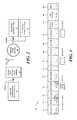
- FIG. 3is a diagram of an exemplary frame structure 22 showing the fields in an exemplary wireless frame transmission from sensor device 12 to network controller 14 .
- each framemay include a preamble field 24 , a SYNC field 26 , a length field 28 indicating the length of the transmission and a DSTADDR field 30 , which represents the destination address, i.e. the address of the wireless access point 16 or network controller 14 to which the frame is being sent.
- wireless node 18appends its address, in this case represented by the SRCADDR field 32 , to the transmission.
- Fields 34 , 36 , 38 , 40 , 42 and 44contain additional information about the wireless node device 18 whose status information is being sought.
- Fields 46 and 48contain information about the sensor device 12 that is sending the response message to network controller 14 .
- Frame structure 22includes fields containing information introduced by different communication layers.
- frames 24 - 30may be transmitted under a first, e.g., CC1101, communication layer, frames 32 - 44 under a second, e.g., the SimplicitTI, communication layer, and frames 46 and 48 under a third, e.g., SmartNET, communication layer.
- the third layerappends the wireless node device 18 status information to frame 22 .
- the nwkDevStatus field 44may be a fixed field that is always present in a frame transmission, or it can be dynamic and the nwkCMD field 40 determines the presence of the nwkDevStatus field 44 .
- Network controller 14 or wireless access point 16can determine if a status device response message contains status from a wireless node device 18 in a number of ways.
- a port field in frame structure 22may indicate that the port that handles the message includes wireless node device status field processing.
- field 40can represent a command that indicates when a wireless node status message is appended to frame 22 .
- FIG. 4illustrates a device status table 50 created by network controller 14 or wireless access point 16 when it processes status information obtained when the wireless node device 18 appends its information to a response message from the sensor device 12 .
- Network controller 14creates and populates a table of wireless node device addresses and associated host sensor device addresses. This table 50 allows the network controller 14 to directly assess the health of a wireless node device 18 by directing a status command to the nodes' address.
- Network controllers 14 or wireless access points 16maintain tables of node health which can be associated to a router table (link path) for managing the network.
- the wireless access point tablesare used in directing the operation of wireless network node devices 18 .
- the table shown in FIG. 4includes a listing of wireless node devices addresses 52 and their corresponding sensor device addresses 54 .
- the status of each wireless node device 18 and sensor device 12is also listed in columns 56 and 58 respectively.
- network controller 14polls each sensor device 12 in the network and awaits a response.
- Each sensor device 12responds to network controller 14 with a message that includes its own address and status and the address and status of each wireless node device 18 that is in communication with the polled sensor device 12 .
- sensor devices 12 a and 12 b addressesare assigned sensor device addresses 10 and 20 respectively. Both sensor devices 12 a and 12 b are associated with a single wireless node device 18 a , which is assigned a wireless node address of (100).
- the table in FIG. 4shows that sensor devices having addresses of (150) and (250) are associated with a wireless node device having a wireless node address of (100). From the table it can be seen that the wireless node device 18 a associated with the listed wireless node address (100) and the sensor devices 12 a and 12 b associated with the sensor device addresses (150) and (200) are all functioning properly.
- Network controller 14uses table 50 to directly assess the health of any wireless node device 18 in the network by directing a status command to the nodes' address or to the address of the sensor device 12 to which the wireless node device 18 is associated.
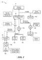
- FIG. 5is a flowchart illustrating the steps taken by the network controller 14 in order to assess the health and status of wireless node devices 18 within the network.
- Network controllervia wireless access point 16 , transmits a status inquiry to the sensor devices 12 in the network that it wishes to obtain status information from (step S 60 ).
- Network controller 14via wireless access point 16 , receives responses messages from the polled sensor devices 12 (step S 62 ).
- Network controller 14creates table 50 (step S 64 ) that lists each responsive sensor device 12 in the network, its corresponding device address, and information regarding its status, i.e., signal strength, noise level, functioning/not-functioning status, etc.
- step S 65network controller 14 determines that the sensor device responses include wireless node device status information
- network controller 14extracts the wireless node device information (step S 66 ), and updates table 50 to include wireless node device status information including the address of the wireless node device 18 (step S 68 ).
- wireless access point 16determines that the sensor device response includes wireless node device status information, extracts the wireless node device information and updates table 50 , which could be maintained either by network controller 14 or wireless access point 16 .
- network controller 14 or wireless access point 16can perform these functions and maintain table 50 .
- network controller 14can determine which sensor devices 12 have associated wireless node devices 18 .
- Network controller 14can determine the health and status of a wireless node device 18 in the network in two ways by referring to table 50 . If no sensor device 12 is associated with the wireless node device 18 , or there is no received response message from the polled sensor device 12 , network controller 14 can direct a status request directly to the address of the associated wireless node 18 . If there is a sensor device 12 address associated with the address of the wireless node device 18 , then network controller 14 can direct a status request to the sensor device 12 and receive appended wireless node device status information in the transmission frame of the response message from sensor device 12 .
- Network controller 14extracts the appended information, determines the status of the wireless node device 18 , and updates table 50 accordingly.
- sensor device 12is unaware of the appended information, thus reducing the processing and memory burden on the sensor device 12 .
- the present inventionprovides a system and method which enables a network controller 14 to communicate with one or more wireless node devices 18 by either sending status requests directly to the wireless node device 18 or by receiving response messages from polled sensor devices 12 , where the sensor device's response message includes address and status information from a wireless node device 18 that is in communication with the polled sensor device.
- Wireless node device 18appends its status information to the sensor device transmission frame from the sensor device 12 and, if necessary, updates other fields in the transmission frame.
- Sensor device 12simply responds to the network controller 14 which now has appended status and address information attached to the frame transmission.
- the present inventioncan be realized in hardware, software, or a combination of hardware and software. Any kind of computing system, or other apparatus adapted for carrying out the methods described herein, is suited to perform the functions described herein.
- a typical combination of hardware and softwarecould be a computer system having one or more processing elements and a computer program stored on a storage medium that, when loaded and executed, controls the computer system such that it carries out the methods described herein.
- the present inventioncan also be embedded in a computer program product, which comprises all the features enabling the implementation of the methods described herein, and which, when loaded in a computing system is able to carry out these methods.
- Storage mediumrefers to any volatile or non-volatile storage device.
- Computer program or application in the present contextmeans any expression, in any language, code or notation, of a set of instructions intended to cause a system having an information processing capability to perform a particular function either directly or after either or both of the following a) conversion to another language, code or notation; b) reproduction in a different material form.
Landscapes
- Engineering & Computer Science (AREA)
- Physics & Mathematics (AREA)
- Automation & Control Theory (AREA)
- General Physics & Mathematics (AREA)
- Electromagnetism (AREA)
- Health & Medical Sciences (AREA)
- Toxicology (AREA)
- Computer Security & Cryptography (AREA)
- General Health & Medical Sciences (AREA)
- Artificial Intelligence (AREA)
- Computer Vision & Pattern Recognition (AREA)
- Theoretical Computer Science (AREA)
- Mobile Radio Communication Systems (AREA)
- Telephonic Communication Services (AREA)
- Arrangements For Transmission Of Measured Signals (AREA)
Abstract
Description
Claims (19)
Priority Applications (8)
| Application Number | Priority Date | Filing Date | Title |
|---|---|---|---|
| US12/684,402US9007181B2 (en) | 2010-01-08 | 2010-01-08 | Method and system for discovery and transparent status reporting for sensor networks |
| AU2010340338AAU2010340338B2 (en) | 2010-01-08 | 2010-12-01 | Method and system for discovery and transparent status reporting for sensor networks |
| EP10795101.4AEP2522004B1 (en) | 2010-01-08 | 2010-12-01 | Method and system for discovery and transparent status reporting for sensor networks |
| PCT/US2010/003065WO2011084125A1 (en) | 2010-01-08 | 2010-12-01 | Method and system for discovery and transparent status reporting for sensor networks |
| KR1020127020320AKR101694838B1 (en) | 2010-01-08 | 2010-12-01 | Method and system for discovery and transparent status reporting for sensor networks |
| BR112012016791-0ABR112012016791B1 (en) | 2010-01-08 | 2010-12-01 | method and device for discovery and transparent status reporting for sensor network |
| CA2786352ACA2786352C (en) | 2010-01-08 | 2010-12-01 | Method and system for discovery and transparent status reporting for sensor networks |
| CN201080063718.5ACN102792346B (en) | 2010-01-08 | 2010-12-01 | Discovery and the method and system of pellucidity report for sensor network |
Applications Claiming Priority (1)
| Application Number | Priority Date | Filing Date | Title |
|---|---|---|---|
| US12/684,402US9007181B2 (en) | 2010-01-08 | 2010-01-08 | Method and system for discovery and transparent status reporting for sensor networks |
Publications (2)
| Publication Number | Publication Date |
|---|---|
| US20110169612A1 US20110169612A1 (en) | 2011-07-14 |
| US9007181B2true US9007181B2 (en) | 2015-04-14 |
Family
ID=43759825
Family Applications (1)
| Application Number | Title | Priority Date | Filing Date |
|---|---|---|---|
| US12/684,402Active2032-01-02US9007181B2 (en) | 2010-01-08 | 2010-01-08 | Method and system for discovery and transparent status reporting for sensor networks |
Country Status (8)
| Country | Link |
|---|---|
| US (1) | US9007181B2 (en) |
| EP (1) | EP2522004B1 (en) |
| KR (1) | KR101694838B1 (en) |
| CN (1) | CN102792346B (en) |
| AU (1) | AU2010340338B2 (en) |
| BR (1) | BR112012016791B1 (en) |
| CA (1) | CA2786352C (en) |
| WO (1) | WO2011084125A1 (en) |
Cited By (1)
| Publication number | Priority date | Publication date | Assignee | Title |
|---|---|---|---|---|
| US10075911B2 (en) | 2011-06-24 | 2018-09-11 | Gassecure As | Wireless sensor networks |
Families Citing this family (7)
| Publication number | Priority date | Publication date | Assignee | Title |
|---|---|---|---|---|
| CN104380360B (en) | 2012-06-22 | 2019-04-30 | 皇家飞利浦有限公司 | Method and apparatus for transferring information between nodes |
| KR101801074B1 (en)* | 2013-04-05 | 2017-11-24 | 후아웨이 테크놀러지 컴퍼니 리미티드 | Method for controlling network access points |
| US9386610B2 (en)* | 2014-10-31 | 2016-07-05 | Aruba Networks, Inc. | Periodic high power beacon broadcasts |
| US9449479B2 (en)* | 2014-12-17 | 2016-09-20 | Colin Rogers | Security system |
| AU2016371209A1 (en)* | 2015-12-18 | 2018-07-05 | Noid Tech, Llc | Control system, method and apparatus for utillity delivery subsystems |
| US10368360B1 (en)* | 2016-03-08 | 2019-07-30 | Quantenna Communications, Inc. | Network event based security and home automation |
| US11534919B2 (en)* | 2019-03-06 | 2022-12-27 | Ademco Inc. | Security sentinel robot |
Citations (56)
| Publication number | Priority date | Publication date | Assignee | Title |
|---|---|---|---|---|
| US5039980A (en)* | 1990-01-26 | 1991-08-13 | Honeywell Inc. | Multi-nodal communication network with coordinated responsibility for global functions by the nodes |
| US5090012A (en)* | 1989-05-22 | 1992-02-18 | Mazda Motor Corporation | Multiplex transmission system for use in a vehicle |
| US5361985A (en)* | 1991-10-01 | 1994-11-08 | American Standard Inc. | Setup tool for a wireless communications system |
| US5920257A (en)* | 1997-07-31 | 1999-07-06 | Mci Communications Corporation | System and method for isolating an outage within a communications network |
| US5949799A (en)* | 1996-12-27 | 1999-09-07 | Cypress Semiconductor Corp. | Minimum-latency data mover with auto-segmentation and reassembly |
| US6150955A (en)* | 1996-10-28 | 2000-11-21 | Tracy Corporation Ii | Apparatus and method for transmitting data via a digital control channel of a digital wireless network |
| US6173207B1 (en)* | 1997-09-22 | 2001-01-09 | Agilent Technologies, Inc. | Real-time control system with non-deterministic communication |
| US6182130B1 (en)* | 1991-03-18 | 2001-01-30 | Echelon Corporation | Method for enhancing the performance of a network |
| US6452946B1 (en)* | 1999-06-04 | 2002-09-17 | Siemens Information And Communications Network, Inc. | Apparatus and method for improving performance in master and slave communications systems |
| US6801524B2 (en)* | 2000-01-31 | 2004-10-05 | Sonim Technologies, Inc. | System for dispatching information packets and method therefor |
| US6826607B1 (en)* | 1999-10-06 | 2004-11-30 | Sensoria Corporation | Apparatus for internetworked hybrid wireless integrated network sensors (WINS) |
| US6859831B1 (en)* | 1999-10-06 | 2005-02-22 | Sensoria Corporation | Method and apparatus for internetworked wireless integrated network sensor (WINS) nodes |
| US20050052282A1 (en)* | 1998-06-02 | 2005-03-10 | Rodgers James L. | Radio frequency identification device |
| US20050078672A1 (en)* | 2003-10-09 | 2005-04-14 | Alaattin Caliskan | Ad Hoc wireless node and network |
| US20050253714A1 (en) | 2004-05-17 | 2005-11-17 | Randy Stephens | Location-based anti-theft and security system and method |
| US20050253722A1 (en) | 2004-05-13 | 2005-11-17 | Cisco Technology, Inc. | Locating, provisioning and identifying devices in a network |
| US20050264429A1 (en)* | 2000-08-09 | 2005-12-01 | Hermary Terrance J | Device and method to establish temporal correspondence in multiple sensor configurations |
| US20060062154A1 (en)* | 2004-09-22 | 2006-03-23 | International Business Machines Corporation | Method and systems for copying data components between nodes of a wireless sensor network |
| US7058481B2 (en)* | 2002-02-25 | 2006-06-06 | General Electric Company | Method and apparatus for centrally-controlled electrical protection system architecture reliability improvement based on sensitivity analysis |
| US20060208892A1 (en) | 2005-03-01 | 2006-09-21 | Ehrman Kenneth S | Mobile portal for rfid applications |
| US7119692B2 (en)* | 2003-11-10 | 2006-10-10 | 3M Innovative Properties Company | System for detecting radio-frequency identification tags |
| US7283045B1 (en)* | 2006-01-26 | 2007-10-16 | The United States Of America As Represented By The Secretary Of The Army | System and method for semi-distributed event warning notification for individual entities, and computer program product therefor |
| US7304976B2 (en)* | 2004-10-13 | 2007-12-04 | Virginia Tech Intellectual Properties, Inc. | Method and apparatus for control and routing of wireless sensor networks |
| WO2007149736A2 (en) | 2006-06-23 | 2007-12-27 | Sun Microsystems, Inc. | Removable data storage media tracking system |
| US20080031139A1 (en)* | 2006-08-04 | 2008-02-07 | Hitachi, Ltd. | Sensor network system and data processing method for sensor network |
| US7378962B2 (en)* | 2004-12-30 | 2008-05-27 | Sap Aktiengesellschaft | Sensor node management and method for monitoring a seal condition of an enclosure |
| US7398164B2 (en)* | 2006-03-07 | 2008-07-08 | Hitachi, Ltd. | Sensor network system, base station, and method to forward measured data |
| US20080232334A1 (en)* | 2007-03-22 | 2008-09-25 | Das Sujit R | Wireless communication network and data aggregation method for the same |
| US20090027061A1 (en)* | 2007-07-25 | 2009-01-29 | Power Monitors, Inc. | Method and apparatus for an electrical conductor monitoring system |
| US20090085769A1 (en)* | 2007-09-27 | 2009-04-02 | Pascal Thubert | Aggregation and propagation of sensor data within neighbor discovery messages in a tree-based ad hoc network |
| US7536255B2 (en)* | 2001-10-12 | 2009-05-19 | Omron Corporation | Sensor or networks with server and information processing system, method and program |
| US20090133122A1 (en)* | 2007-11-21 | 2009-05-21 | Bon Hyun Koo | Method and system for detecting suspicious frame in wireless sensor network |
| US7564405B2 (en)* | 1999-06-18 | 2009-07-21 | Pfizer, Inc. | Object locator |
| US7584076B2 (en)* | 2005-10-26 | 2009-09-01 | Ista International Gmbh | Method for communication of multiple sensor nodes in a sensor network |
| US7660860B2 (en)* | 2004-11-17 | 2010-02-09 | Samsung Electro-Mechanics Co., Ltd | Method for discovery reply packet transmission in communication network |
| US7675867B1 (en)* | 2006-04-19 | 2010-03-09 | Owl Computing Technologies, Inc. | One-way data transfer system with built-in data verification mechanism |
| US7683761B2 (en)* | 2005-01-26 | 2010-03-23 | Battelle Memorial Institute | Method for autonomous establishment and utilization of an active-RF tag network |
| US7689295B2 (en)* | 2003-06-26 | 2010-03-30 | International Business Machines Corporation | Method and system for monitoring and control of complex systems based on a programmable network processor |
| US7706906B2 (en)* | 2005-10-11 | 2010-04-27 | Hitachi, Ltd. | Work management support method and work management support system which use sensor nodes |
| US20100102926A1 (en)* | 2007-03-13 | 2010-04-29 | Syngenta Crop Protection, Inc. | Methods and systems for ad hoc sensor network |
| US7848905B2 (en)* | 2000-12-26 | 2010-12-07 | Troxler Electronic Laboratories, Inc. | Methods, systems, and computer program products for locating and tracking objects |
| US7885251B2 (en)* | 2005-12-21 | 2011-02-08 | Korea Electronics Technology Institute | Real-time wireless sensor network protocol having linear configuration |
| US7904052B2 (en)* | 2005-02-23 | 2011-03-08 | Hitachi, Ltd. | Sensor net management method |
| US7920067B2 (en)* | 2007-04-16 | 2011-04-05 | American Air Liquide, Inc. | Wireless medical gases management system |
| US7937595B1 (en)* | 2003-06-27 | 2011-05-03 | Zoran Corporation | Integrated encryption/decryption functionality in a digital TV/PVR system-on-chip |
| US7953809B2 (en)* | 2002-04-24 | 2011-05-31 | Ipventure, Inc. | Method and system for enhanced messaging |
| US20110131013A1 (en)* | 2008-07-31 | 2011-06-02 | Byoung Hoon Lee | Ubiquitous monitoring system |
| US20110148591A1 (en)* | 2002-05-30 | 2011-06-23 | Reynolds Matthew S | Methods and apparatus for operating a radio device |
| US7982603B2 (en)* | 2006-03-28 | 2011-07-19 | Hitachi, Ltd. | Sensor net system, sensor net system data managing method, and sensor net system data managing program |
| US7994911B2 (en)* | 2009-09-28 | 2011-08-09 | Checkpoint Systems, Inc. | System, method, and apparatus for triggering an alarm |
| US8090855B2 (en)* | 2003-03-21 | 2012-01-03 | Cisco Technology, Inc. | Replenishing a user account with more access resources needed for accessing network services |
| US20120047113A1 (en)* | 2010-08-18 | 2012-02-23 | Marcelo Weinberger | Multiple-source data compression |
| US8132225B2 (en)* | 2004-09-30 | 2012-03-06 | Rockwell Automation Technologies, Inc. | Scalable and flexible information security for industrial automation |
| US8223766B2 (en)* | 2007-02-28 | 2012-07-17 | Fujitsu Limited | Communication method for system including client device and plural server devices |
| US8275313B1 (en)* | 2007-01-15 | 2012-09-25 | Advanced Distributed Sensor Systems | Long range, low power, mesh networking without concurrent timing |
| US8427338B2 (en)* | 2009-04-16 | 2013-04-23 | Vahid Zarei Seyd Abad | Architecture, system and method for modular environmental conditions and object sensing |
Family Cites Families (1)
| Publication number | Priority date | Publication date | Assignee | Title |
|---|---|---|---|---|
| US536198A (en)* | 1895-03-26 | everard |
- 2010
- 2010-01-08USUS12/684,402patent/US9007181B2/enactiveActive
- 2010-12-01CACA2786352Apatent/CA2786352C/ennot_activeExpired - Fee Related
- 2010-12-01EPEP10795101.4Apatent/EP2522004B1/ennot_activeNot-in-force
- 2010-12-01CNCN201080063718.5Apatent/CN102792346B/ennot_activeExpired - Fee Related
- 2010-12-01AUAU2010340338Apatent/AU2010340338B2/ennot_activeCeased
- 2010-12-01KRKR1020127020320Apatent/KR101694838B1/ennot_activeExpired - Fee Related
- 2010-12-01BRBR112012016791-0Apatent/BR112012016791B1/ennot_activeIP Right Cessation
- 2010-12-01WOPCT/US2010/003065patent/WO2011084125A1/enactiveApplication Filing
Patent Citations (64)
| Publication number | Priority date | Publication date | Assignee | Title |
|---|---|---|---|---|
| US5090012A (en)* | 1989-05-22 | 1992-02-18 | Mazda Motor Corporation | Multiplex transmission system for use in a vehicle |
| US5039980A (en)* | 1990-01-26 | 1991-08-13 | Honeywell Inc. | Multi-nodal communication network with coordinated responsibility for global functions by the nodes |
| US6182130B1 (en)* | 1991-03-18 | 2001-01-30 | Echelon Corporation | Method for enhancing the performance of a network |
| US5361985A (en)* | 1991-10-01 | 1994-11-08 | American Standard Inc. | Setup tool for a wireless communications system |
| US6150955A (en)* | 1996-10-28 | 2000-11-21 | Tracy Corporation Ii | Apparatus and method for transmitting data via a digital control channel of a digital wireless network |
| US5949799A (en)* | 1996-12-27 | 1999-09-07 | Cypress Semiconductor Corp. | Minimum-latency data mover with auto-segmentation and reassembly |
| US5920257A (en)* | 1997-07-31 | 1999-07-06 | Mci Communications Corporation | System and method for isolating an outage within a communications network |
| US6173207B1 (en)* | 1997-09-22 | 2001-01-09 | Agilent Technologies, Inc. | Real-time control system with non-deterministic communication |
| US20050052282A1 (en)* | 1998-06-02 | 2005-03-10 | Rodgers James L. | Radio frequency identification device |
| US6452946B1 (en)* | 1999-06-04 | 2002-09-17 | Siemens Information And Communications Network, Inc. | Apparatus and method for improving performance in master and slave communications systems |
| US7564405B2 (en)* | 1999-06-18 | 2009-07-21 | Pfizer, Inc. | Object locator |
| US6826607B1 (en)* | 1999-10-06 | 2004-11-30 | Sensoria Corporation | Apparatus for internetworked hybrid wireless integrated network sensors (WINS) |
| US6859831B1 (en)* | 1999-10-06 | 2005-02-22 | Sensoria Corporation | Method and apparatus for internetworked wireless integrated network sensor (WINS) nodes |
| US6801524B2 (en)* | 2000-01-31 | 2004-10-05 | Sonim Technologies, Inc. | System for dispatching information packets and method therefor |
| US20050264429A1 (en)* | 2000-08-09 | 2005-12-01 | Hermary Terrance J | Device and method to establish temporal correspondence in multiple sensor configurations |
| US7848905B2 (en)* | 2000-12-26 | 2010-12-07 | Troxler Electronic Laboratories, Inc. | Methods, systems, and computer program products for locating and tracking objects |
| US7536255B2 (en)* | 2001-10-12 | 2009-05-19 | Omron Corporation | Sensor or networks with server and information processing system, method and program |
| US7058481B2 (en)* | 2002-02-25 | 2006-06-06 | General Electric Company | Method and apparatus for centrally-controlled electrical protection system architecture reliability improvement based on sensitivity analysis |
| US7953809B2 (en)* | 2002-04-24 | 2011-05-31 | Ipventure, Inc. | Method and system for enhanced messaging |
| US20110148591A1 (en)* | 2002-05-30 | 2011-06-23 | Reynolds Matthew S | Methods and apparatus for operating a radio device |
| US8090855B2 (en)* | 2003-03-21 | 2012-01-03 | Cisco Technology, Inc. | Replenishing a user account with more access resources needed for accessing network services |
| US7689295B2 (en)* | 2003-06-26 | 2010-03-30 | International Business Machines Corporation | Method and system for monitoring and control of complex systems based on a programmable network processor |
| US7937595B1 (en)* | 2003-06-27 | 2011-05-03 | Zoran Corporation | Integrated encryption/decryption functionality in a digital TV/PVR system-on-chip |
| US7436789B2 (en)* | 2003-10-09 | 2008-10-14 | Sarnoff Corporation | Ad Hoc wireless node and network |
| US20050078672A1 (en)* | 2003-10-09 | 2005-04-14 | Alaattin Caliskan | Ad Hoc wireless node and network |
| US7119692B2 (en)* | 2003-11-10 | 2006-10-10 | 3M Innovative Properties Company | System for detecting radio-frequency identification tags |
| US7648070B2 (en)* | 2004-05-13 | 2010-01-19 | Cisco Technology, Inc. | Locating, provisioning and identifying devices in a network |
| US20050253722A1 (en) | 2004-05-13 | 2005-11-17 | Cisco Technology, Inc. | Locating, provisioning and identifying devices in a network |
| US20050253714A1 (en) | 2004-05-17 | 2005-11-17 | Randy Stephens | Location-based anti-theft and security system and method |
| US7769848B2 (en)* | 2004-09-22 | 2010-08-03 | International Business Machines Corporation | Method and systems for copying data components between nodes of a wireless sensor network |
| US20060062154A1 (en)* | 2004-09-22 | 2006-03-23 | International Business Machines Corporation | Method and systems for copying data components between nodes of a wireless sensor network |
| US8132225B2 (en)* | 2004-09-30 | 2012-03-06 | Rockwell Automation Technologies, Inc. | Scalable and flexible information security for industrial automation |
| US7304976B2 (en)* | 2004-10-13 | 2007-12-04 | Virginia Tech Intellectual Properties, Inc. | Method and apparatus for control and routing of wireless sensor networks |
| US7660860B2 (en)* | 2004-11-17 | 2010-02-09 | Samsung Electro-Mechanics Co., Ltd | Method for discovery reply packet transmission in communication network |
| US7378962B2 (en)* | 2004-12-30 | 2008-05-27 | Sap Aktiengesellschaft | Sensor node management and method for monitoring a seal condition of an enclosure |
| US7683761B2 (en)* | 2005-01-26 | 2010-03-23 | Battelle Memorial Institute | Method for autonomous establishment and utilization of an active-RF tag network |
| US7904052B2 (en)* | 2005-02-23 | 2011-03-08 | Hitachi, Ltd. | Sensor net management method |
| US20060208892A1 (en) | 2005-03-01 | 2006-09-21 | Ehrman Kenneth S | Mobile portal for rfid applications |
| US7706906B2 (en)* | 2005-10-11 | 2010-04-27 | Hitachi, Ltd. | Work management support method and work management support system which use sensor nodes |
| US7584076B2 (en)* | 2005-10-26 | 2009-09-01 | Ista International Gmbh | Method for communication of multiple sensor nodes in a sensor network |
| US7885251B2 (en)* | 2005-12-21 | 2011-02-08 | Korea Electronics Technology Institute | Real-time wireless sensor network protocol having linear configuration |
| US7283045B1 (en)* | 2006-01-26 | 2007-10-16 | The United States Of America As Represented By The Secretary Of The Army | System and method for semi-distributed event warning notification for individual entities, and computer program product therefor |
| US7398164B2 (en)* | 2006-03-07 | 2008-07-08 | Hitachi, Ltd. | Sensor network system, base station, and method to forward measured data |
| US7982603B2 (en)* | 2006-03-28 | 2011-07-19 | Hitachi, Ltd. | Sensor net system, sensor net system data managing method, and sensor net system data managing program |
| US7675867B1 (en)* | 2006-04-19 | 2010-03-09 | Owl Computing Technologies, Inc. | One-way data transfer system with built-in data verification mechanism |
| WO2007149736A2 (en) | 2006-06-23 | 2007-12-27 | Sun Microsystems, Inc. | Removable data storage media tracking system |
| US20080031139A1 (en)* | 2006-08-04 | 2008-02-07 | Hitachi, Ltd. | Sensor network system and data processing method for sensor network |
| US8159945B2 (en)* | 2006-08-04 | 2012-04-17 | Hitachi, Ltd. | Sensor network system and data processing method for sensor network |
| US8275313B1 (en)* | 2007-01-15 | 2012-09-25 | Advanced Distributed Sensor Systems | Long range, low power, mesh networking without concurrent timing |
| US8223766B2 (en)* | 2007-02-28 | 2012-07-17 | Fujitsu Limited | Communication method for system including client device and plural server devices |
| US20100102926A1 (en)* | 2007-03-13 | 2010-04-29 | Syngenta Crop Protection, Inc. | Methods and systems for ad hoc sensor network |
| US20080232334A1 (en)* | 2007-03-22 | 2008-09-25 | Das Sujit R | Wireless communication network and data aggregation method for the same |
| US7920067B2 (en)* | 2007-04-16 | 2011-04-05 | American Air Liquide, Inc. | Wireless medical gases management system |
| US20090027061A1 (en)* | 2007-07-25 | 2009-01-29 | Power Monitors, Inc. | Method and apparatus for an electrical conductor monitoring system |
| US7969159B2 (en)* | 2007-07-25 | 2011-06-28 | Power Monitors, Inc. | Method and apparatus for an electrical conductor monitoring system |
| US20120063436A1 (en)* | 2007-09-27 | 2012-03-15 | Cisco Technology, Inc. | Aggregation and propagation of sensor data within neighbor discovery messages in a tree-based ad hoc network |
| US20090085769A1 (en)* | 2007-09-27 | 2009-04-02 | Pascal Thubert | Aggregation and propagation of sensor data within neighbor discovery messages in a tree-based ad hoc network |
| US8085686B2 (en)* | 2007-09-27 | 2011-12-27 | Cisco Technology, Inc. | Aggregation and propagation of sensor data within neighbor discovery messages in a tree-based ad hoc network |
| US20090133122A1 (en)* | 2007-11-21 | 2009-05-21 | Bon Hyun Koo | Method and system for detecting suspicious frame in wireless sensor network |
| US8136159B2 (en)* | 2007-11-21 | 2012-03-13 | Samsung Electronics Co., Ltd. | Method and system for detecting suspicious frame in wireless sensor network |
| US20110131013A1 (en)* | 2008-07-31 | 2011-06-02 | Byoung Hoon Lee | Ubiquitous monitoring system |
| US8427338B2 (en)* | 2009-04-16 | 2013-04-23 | Vahid Zarei Seyd Abad | Architecture, system and method for modular environmental conditions and object sensing |
| US7994911B2 (en)* | 2009-09-28 | 2011-08-09 | Checkpoint Systems, Inc. | System, method, and apparatus for triggering an alarm |
| US20120047113A1 (en)* | 2010-08-18 | 2012-02-23 | Marcelo Weinberger | Multiple-source data compression |
Non-Patent Citations (1)
| Title |
|---|
| International Search Report and Written Opinion dated Apr. 27, 2011 for International Application No. PCT/US2010/003065, International Filing Date: Dec. 1, 2010 consisting of 10-pages. |
Cited By (1)
| Publication number | Priority date | Publication date | Assignee | Title |
|---|---|---|---|---|
| US10075911B2 (en) | 2011-06-24 | 2018-09-11 | Gassecure As | Wireless sensor networks |
Also Published As
| Publication number | Publication date |
|---|---|
| CN102792346A (en) | 2012-11-21 |
| EP2522004B1 (en) | 2018-02-28 |
| WO2011084125A1 (en) | 2011-07-14 |
| AU2010340338A1 (en) | 2012-07-19 |
| US20110169612A1 (en) | 2011-07-14 |
| BR112012016791A2 (en) | 2018-03-27 |
| EP2522004A1 (en) | 2012-11-14 |
| AU2010340338B2 (en) | 2015-12-10 |
| KR20120113768A (en) | 2012-10-15 |
| KR101694838B1 (en) | 2017-01-10 |
| CA2786352A1 (en) | 2011-07-14 |
| CN102792346B (en) | 2016-08-03 |
| BR112012016791B1 (en) | 2020-10-13 |
| CA2786352C (en) | 2019-05-14 |
Similar Documents
| Publication | Publication Date | Title |
|---|---|---|
| US9007181B2 (en) | Method and system for discovery and transparent status reporting for sensor networks | |
| JP5156100B2 (en) | Method for real-time location tracking of individuals via multi-network in store | |
| US7433648B2 (en) | System and a node used in the system for wireless communication and sensory monitoring | |
| US6405102B1 (en) | RF-interrogatable processing system | |
| EP2070021B1 (en) | Electronic article surveillance enabled radio frequency identification system and method | |
| EP3182765B1 (en) | Method and device for bluetooth low power communication | |
| US10657340B2 (en) | Systems and methods for improved tag position tracking | |
| US11611851B2 (en) | Location tracking of assets | |
| JP2011510377A (en) | Real-time location tracking system for shoppers using a multi-network for communication | |
| US20080079564A1 (en) | Method and system for devices to communicate wirelessly using RFID air protocols | |
| HK1176731B (en) | Method and system for discovery and transparent status reporting for sensor networks | |
| HK1176731A (en) | Method and system for discovery and transparent status reporting for sensor networks | |
| AU2016404348B2 (en) | Position specifying device and program | |
| Mitra et al. | A heuristic approach for mobile phone bases information management system in wireless sensor network | |
| TW200901778A (en) | Location system with wireless sensor network | |
| CA2372463A1 (en) | Radiographic network |
Legal Events
| Date | Code | Title | Description |
|---|---|---|---|
| AS | Assignment | Owner name:SENSORMATIC ELECTRONICS, LLC, FLORIDA Free format text:ASSIGNMENT OF ASSIGNORS INTEREST;ASSIGNORS:ALICOT, JORGE F.;RELIHAN, TIMOTHY J.;REEL/FRAME:023753/0125 Effective date:20100107 | |
| AS | Assignment | Owner name:ADT SERVICES GMBH, SWITZERLAND Free format text:ASSIGNMENT OF ASSIGNORS INTEREST;ASSIGNOR:SENSORMATIC ELECTRONICS, LLC;REEL/FRAME:029894/0856 Effective date:20130214 | |
| AS | Assignment | Owner name:TYCO FIRE & SECURITY GMBH, SWITZERLAND Free format text:MERGER;ASSIGNOR:ADT SERVICES GMBH;REEL/FRAME:030290/0731 Effective date:20130326 | |
| STCF | Information on status: patent grant | Free format text:PATENTED CASE | |
| AS | Assignment | Owner name:SENSORMATIC ELECTRONICS, LLC, FLORIDA Free format text:ASSIGNMENT OF ASSIGNORS INTEREST;ASSIGNOR:TYCO FIRE & SECURITY GMBH;REEL/FRAME:047182/0674 Effective date:20180927 | |
| AS | Assignment | Owner name:SENSORMATIC ELECTRONICS, LLC, FLORIDA Free format text:ASSIGNMENT OF ASSIGNORS INTEREST;ASSIGNOR:TYCO FIRE & SECURITY GMBH;REEL/FRAME:047188/0715 Effective date:20180927 | |
| MAFP | Maintenance fee payment | Free format text:PAYMENT OF MAINTENANCE FEE, 4TH YEAR, LARGE ENTITY (ORIGINAL EVENT CODE: M1551); ENTITY STATUS OF PATENT OWNER: LARGE ENTITY Year of fee payment:4 | |
| MAFP | Maintenance fee payment | Free format text:PAYMENT OF MAINTENANCE FEE, 8TH YEAR, LARGE ENTITY (ORIGINAL EVENT CODE: M1552); ENTITY STATUS OF PATENT OWNER: LARGE ENTITY Year of fee payment:8 |