US9007141B2 - Interface for communication between voltage domains - Google Patents
Interface for communication between voltage domainsDownload PDFInfo
- Publication number
- US9007141B2 US9007141B2US13/478,737US201213478737AUS9007141B2US 9007141 B2US9007141 B2US 9007141B2US 201213478737 AUS201213478737 AUS 201213478737AUS 9007141 B2US9007141 B2US 9007141B2
- Authority
- US
- United States
- Prior art keywords
- capacitive
- plate
- voltage
- substrate
- communication signals
- Prior art date
- Legal status (The legal status is an assumption and is not a legal conclusion. Google has not performed a legal analysis and makes no representation as to the accuracy of the status listed.)
- Active, expires
Links
Images


Classifications
- H—ELECTRICITY
- H01—ELECTRIC ELEMENTS
- H01G—CAPACITORS; CAPACITORS, RECTIFIERS, DETECTORS, SWITCHING DEVICES, LIGHT-SENSITIVE OR TEMPERATURE-SENSITIVE DEVICES OF THE ELECTROLYTIC TYPE
- H01G4/00—Fixed capacitors; Processes of their manufacture
- H01G4/38—Multiple capacitors, i.e. structural combinations of fixed capacitors
- H01G4/385—Single unit multiple capacitors, e.g. dual capacitor in one coil
- H—ELECTRICITY
- H01—ELECTRIC ELEMENTS
- H01G—CAPACITORS; CAPACITORS, RECTIFIERS, DETECTORS, SWITCHING DEVICES, LIGHT-SENSITIVE OR TEMPERATURE-SENSITIVE DEVICES OF THE ELECTROLYTIC TYPE
- H01G4/00—Fixed capacitors; Processes of their manufacture
- H01G4/002—Details
- H01G4/018—Dielectrics
- H01G4/06—Solid dielectrics
- H—ELECTRICITY
- H01—ELECTRIC ELEMENTS
- H01L—SEMICONDUCTOR DEVICES NOT COVERED BY CLASS H10
- H01L23/00—Details of semiconductor or other solid state devices
- H01L23/48—Arrangements for conducting electric current to or from the solid state body in operation, e.g. leads, terminal arrangements ; Selection of materials therefor
- H—ELECTRICITY
- H01—ELECTRIC ELEMENTS
- H01L—SEMICONDUCTOR DEVICES NOT COVERED BY CLASS H10
- H01L23/00—Details of semiconductor or other solid state devices
- H01L23/58—Structural electrical arrangements for semiconductor devices not otherwise provided for, e.g. in combination with batteries
- H01L23/64—Impedance arrangements
- H01L23/642—Capacitive arrangements
- H01L28/60—
- H—ELECTRICITY
- H01—ELECTRIC ELEMENTS
- H01P—WAVEGUIDES; RESONATORS, LINES, OR OTHER DEVICES OF THE WAVEGUIDE TYPE
- H01P1/00—Auxiliary devices
- H01P1/04—Fixed joints
- H—ELECTRICITY
- H03—ELECTRONIC CIRCUITRY
- H03H—IMPEDANCE NETWORKS, e.g. RESONANT CIRCUITS; RESONATORS
- H03H7/00—Multiple-port networks comprising only passive electrical elements as network components
- H03H7/004—Capacitive coupling circuits not otherwise provided for
- H04B5/0012—
- H—ELECTRICITY
- H04—ELECTRIC COMMUNICATION TECHNIQUE
- H04B—TRANSMISSION
- H04B5/00—Near-field transmission systems, e.g. inductive or capacitive transmission systems
- H04B5/20—Near-field transmission systems, e.g. inductive or capacitive transmission systems characterised by the transmission technique; characterised by the transmission medium
- H04B5/22—Capacitive coupling
- H—ELECTRICITY
- H10—SEMICONDUCTOR DEVICES; ELECTRIC SOLID-STATE DEVICES NOT OTHERWISE PROVIDED FOR
- H10D—INORGANIC ELECTRIC SEMICONDUCTOR DEVICES
- H10D1/00—Resistors, capacitors or inductors
- H10D1/60—Capacitors
- H10D1/68—Capacitors having no potential barriers
- H10D1/692—Electrodes
- H—ELECTRICITY
- H01—ELECTRIC ELEMENTS
- H01L—SEMICONDUCTOR DEVICES NOT COVERED BY CLASS H10
- H01L2224/00—Indexing scheme for arrangements for connecting or disconnecting semiconductor or solid-state bodies and methods related thereto as covered by H01L24/00
- H01L2224/01—Means for bonding being attached to, or being formed on, the surface to be connected, e.g. chip-to-package, die-attach, "first-level" interconnects; Manufacturing methods related thereto
- H01L2224/42—Wire connectors; Manufacturing methods related thereto
- H01L2224/47—Structure, shape, material or disposition of the wire connectors after the connecting process
- H01L2224/48—Structure, shape, material or disposition of the wire connectors after the connecting process of an individual wire connector
- H01L2224/481—Disposition
- H01L2224/48135—Connecting between different semiconductor or solid-state bodies, i.e. chip-to-chip
- H01L2224/48137—Connecting between different semiconductor or solid-state bodies, i.e. chip-to-chip the bodies being arranged next to each other, e.g. on a common substrate
- H—ELECTRICITY
- H01—ELECTRIC ELEMENTS
- H01L—SEMICONDUCTOR DEVICES NOT COVERED BY CLASS H10
- H01L25/00—Assemblies consisting of a plurality of semiconductor or other solid state devices
- H01L25/03—Assemblies consisting of a plurality of semiconductor or other solid state devices all the devices being of a type provided for in a single subclass of subclasses H10B, H10D, H10F, H10H, H10K or H10N, e.g. assemblies of rectifier diodes
- H01L25/04—Assemblies consisting of a plurality of semiconductor or other solid state devices all the devices being of a type provided for in a single subclass of subclasses H10B, H10D, H10F, H10H, H10K or H10N, e.g. assemblies of rectifier diodes the devices not having separate containers
- H01L25/065—Assemblies consisting of a plurality of semiconductor or other solid state devices all the devices being of a type provided for in a single subclass of subclasses H10B, H10D, H10F, H10H, H10K or H10N, e.g. assemblies of rectifier diodes the devices not having separate containers the devices being of a type provided for in group H10D89/00
- H01L25/0655—Assemblies consisting of a plurality of semiconductor or other solid state devices all the devices being of a type provided for in a single subclass of subclasses H10B, H10D, H10F, H10H, H10K or H10N, e.g. assemblies of rectifier diodes the devices not having separate containers the devices being of a type provided for in group H10D89/00 the devices being arranged next to each other
- H—ELECTRICITY
- H01—ELECTRIC ELEMENTS
- H01L—SEMICONDUCTOR DEVICES NOT COVERED BY CLASS H10
- H01L2924/00—Indexing scheme for arrangements or methods for connecting or disconnecting semiconductor or solid-state bodies as covered by H01L24/00
- H01L2924/0001—Technical content checked by a classifier
- H01L2924/00014—Technical content checked by a classifier the subject-matter covered by the group, the symbol of which is combined with the symbol of this group, being disclosed without further technical details
Definitions
- aspects of the present disclosurerelate to apparatuses, devices, and methods involving capacitive isolation.
- aspects of the present disclosurerelate to the transmission of data between circuits that operate in different voltage domains.
- circuitsmay be galvanically isolated using capacitive coupling on signal paths between the circuits.
- the circuitsoperate in separate voltage domains that are not referenced to one another by a common ground voltage level.
- large voltage differencesmay arise between the corresponding voltage domains.
- Galvanic isolationhas been used for a variety of different applications. For instance, galvanic isolation can be provided between multiple integrated circuit chips, which can be located within the same package or in different packages. Signals can be passed between the integrated circuits using galvanic isolation techniques.
- One method of galvanic isolationuses capacitors on signal paths between two circuits as a means of blocking DC voltages and attenuating low-frequency signals while transmitting high-frequency signals. Due to large voltage differences that may arise between isolated voltage domains for some applications, capacitors having high breakdown voltage may be required. However, physical space constraints may make it difficult to implement capacitors having the required breakdown voltage.
- a parallel plate capacitormay be implemented alongside other circuitry in an integrated circuit (IC) using conventional processes (e.g., CMOS, complementary metal-oxide-semiconductor). Two capacitive plates are implemented in different metallization layers of the IC and are separated by a dielectric layer. The breakdown voltage of the parallel plate capacitor is dependent on the thickness of the dielectric layer. For higher voltage applications, the thickness of the dielectric layer is increased to provide a higher breakdown voltage. However, in certain CMOS processes, the maximum dielectric thickness that can be implemented is limited to about 5-10 um. For some applications, this thickness is not sufficient to guarantee sufficient breakdown voltage.
- circuitsmay be galvanically isolated using capacitive coupling on signal paths between the circuits.
- the circuitsoperate in separate voltage domains that are not referenced to one another by a common ground voltage level.
- voltage differencesmay arise between the corresponding voltage domains.
- the voltage differencescan be relatively large in comparison to the voltages within each of the separate voltage domains.
- circuitryfor isolation and communication of signals between circuits operating in different voltage domains using capacitive coupling.
- the embodimentsutilize capacitive structures that can be useful for providing high breakdown voltages.
- the capacitive structuresinclude three capacitive plates arranged to have two plates located in an upper layer and one plate located in a lower layer. In operation, the capacitive structure functions as two capacitors coupled in series (e.g., an input plate and an intermediate plate forming a capacitor and the plate and the output plate for another capacitor). This configuration can be particularly useful for providing a high overall breakdown voltage of the structure.
- Embodiments of the present disclosureare directed toward an isolation circuit having a first capacitive structure in a first voltage domain.
- the first capacitive structurecan include a first conducting substrate that is electrically connected to a reference voltage of the first voltage domain, such as ground.
- the substratemay also have active CMOS components (e.g., transistors) that require that conductive substrate to be connected to ground.
- CMOS componentse.g., transistors
- the input and intermediate capacitive platesfunction as a first capacitor.
- the intermediate and output capacitive platesfunction as a second capacitor arranged in series with the first capacitor.
- a first dielectric layerdefines/provides a first breakdown voltage by way of the physical separation between the intermediate capacitor plate and each of the input and output capacitor plates.
- the intermediate capacitor platecan be located below each of the input and output capacitor plates (e.g., in a lower stack layer).
- a second dielectric layeris configured and arranged to provide substantially the same breakdown voltage as the first breakdown voltage. This is accomplished by setting the distance of the physical separation provided between the conducting substrate and the first intermediate capacitor plate accordingly.
- the two dielectric layerscan be part of the same dielectric stack, they are referred to as different layers due to the stacked relationship between the respective plates and/or conductive substrate.
- the above arrangement of platescan then be repeated for a second capacitive structure in a second voltage domain, which is then arranged in series with the first capacitive structure.
- the capacitive structuresmay be implemented on a substrate having various portions connected to one or more reference voltages (e.g., ground voltages).
- Each capacitive structureincludes a first dielectric layer separating the input and output capacitive plates from the intermediate capacitive plate.
- Each capacitive structurealso includes a second dielectric layer separating the intermediate capacitive plate the substrate.
- the first and second dielectric layershave thicknesses such that a first breakdown voltage between the capacitive plates is approximately equal to a second breakdown voltage between the lower capacitive plate and the reference voltage tied to the substrate.
- the capacitive structuresmay be implemented on a silicon-on-insulator (SOI) substrate, in which a silicon layer is separated from a silicon handle wafer by an insulating oxide layer.
- SOIsilicon-on-insulator
- the capacitive structuresare arranged such that both the second dielectric layer and the buried oxide provide isolation between the intermediate lower capacitive plate and the substrate.
- Use of the buried oxide layer of the SOI substrate in this mannerprovides allows the thickness of the first dielectric layer to be increased compared to a standard silicon wafer substrate. As a result, the breakdown voltage between the capacitive plates is increased.
- a method of communication between first and second voltage domainsis provided. Communication signals are transmitted from a transmitter circuit located in a first voltage domain on a first substrate. Capacitive isolation is provided for the communication signals between the first voltage domain and a second voltage domain by communicating the transmitted communication signals through an isolation circuit.
- the isolation circuitincludes a first capacitive structure located on the first substrate to provide the communication signal from the first voltage domain to an unreferenced voltage domain.
- the isolation circuitincludes a second capacitive structure located on a second substrate that is used to provide the communication signals from the unreferenced voltage domain to a second voltage domain.
- a receiver circuitis located on the second substrate and is configured to receive the communication signals at an input in the second voltage domain from the second capacitive structure.
- a deviceincludes a transmitter circuit that is in a first voltage domain and that is configured and arranged to transmit communication signals.
- a receiver circuitis located in a second voltage domain and has an input that is configured and arranged to receive the communication signals in the second voltage domain.
- An isolation circuitis configured and arranged to provide capacitive isolation for the communication signals between the first and second voltage domains.
- the isolation circuitincludes a first and second capacitive structure.
- the first capacitive structureis located on a first substrate in a first voltage domain.
- the first capacitive structureincludes a first/input capacitive plate configured and arranged to receive the communication signals from the transmitter circuit and in the first voltage domain.
- a second/intermediate capacitive plateis configured and arranged to receive the communication signals from the first capacitive plate at a first floating node of the isolation circuit.
- a third/output capacitive plateis configured and arranged to receive the communication signals from the second capacitive plate at a second floating node of the isolation circuit.
- a first dielectric layeris configured and arranged to provide first breakdown voltages of the first capacitive structure by providing an electrical and physical separation between the second capacitive plate and each of the first and third capacitive plates, the physical separation having a first distance.
- a second dielectric layerprovides an electrical and physical separation between the first substrate and the second capacitive plate to provide substantially the same breakdown voltages as the first breakdown voltages.
- the second capacitive structureis located on a second substrate in a second voltage domain.
- This second capacitive structureincludes a fourth (input) capacitive plate configured and arranged to receive the communication signals from the third capacitive plate at a third floating node of the isolation circuit.
- a fifth (intermediate) capacitive plateis configured and arranged to receive the communication signals from the fourth capacitive plate at a fourth floating node of the isolation circuit.
- a sixth (output) capacitive plateis configured and arranged to receive the communication signals from the fifth capacitive plate and to provide the communication signals to the input of the receiver.
- a third dielectric layerdefines second breakdown voltages of the second capacitive structure by providing an electrical and physical separation between the fifth capacitive plate and each of the fourth and sixth capacitive plates, the physical separation having a second distance.
- a fourth dielectric layerprovides an electrical and physical separation between the second substrate and the fifth capacitive plate to provide substantially the same breakdown voltages as the second breakdown voltages.
- Various embodimentsare directed toward methods that include transmitting communication signals from a transmitter circuit located on a first substrate that is in a first voltage domain.
- Capacitive isolationis provided for the communication signals between the first voltage domain and a second voltage domain by communicating the transmitted communication signals through the isolation circuit by capacitively coupling the communication signals from the first voltage domain to an unreferenced domain using a first capacitive structure located on the first substrate.
- the isolation circuitcan include the first and second isolation structures described in the previous embodiments.
- the communication signalsare then received from the second capacitive structure at an input of a receiver circuit that is in the second voltage domain.
- FIG. 1depicts a block diagram of a system for communicating between two isolated voltage domains, consistent with one or more embodiments of the present disclosure
- FIG. 2shows a top view of a high breakdown voltage capacitive structure, consistent with one or more embodiments of the present disclosure
- FIG. 3shows a cross sectional view of the capacitive structure shown in FIG. 2 , consistent with one or more embodiments of the present disclosure
- FIG. 4shows a cross sectional view of the capacitive structure shown in FIG. 2 , consistent with one or more embodiments of the present disclosure
- FIG. 5shows a top view of the capacitive structure formed on a partially floating substrate, consistent with one or more embodiments of the present disclosure
- FIG. 6shows a cross sectional view of the capacitive structure shown in FIG. 5 , consistent with one or more embodiments of the present disclosure
- FIG. 7shows a cross sectional view of the several series capacitive structures, consistent with one or more embodiments of the present disclosure
- FIG. 8shows a method of manufacturing a capacitive structure, consistent with one or more embodiments of the present disclosure.
- FIG. 9illustrates a method of communication between first and second voltage domains, consistent with one or more embodiments of the present disclosure.
- circuitsmay be galvanically isolated using capacitive coupling on signal paths between the circuits.
- circuitsmay be galvanically isolated using capacitive coupling on signal paths between the circuits.
- Particular embodimentsuse parallel plate capacitor structures to provide capacitive coupling.
- an isolation circuitis used to provide capacitive coupling for communication between circuits operating in different voltage domains.
- the capacitive isolation circuitsinclude three capacitive plates arranged to have two (e.g., input and output) plates located in an upper layer and another (e.g., intermediate) plate located in a lower layer. The arrangement of the capacitive plates creates a capacitive field between the plate in the lower layer and each of the plates in the upper layer, respectively.
- the isolation circuitfunctions as two capacitors connected together in series. As such, breakdown voltage measured between the two upper plates, is effectively doubled in comparison to a two-plate capacitor having the same the dielectric thickness constraints. However, even where capacitors are connected in series on the same substrate, breakdown voltage can be reduced due to breakdown between one of the capacitive plates and the substrate. This breakdown can be particularly problematic for CMOS applications, where the substrate may be connected to a ground voltage.
- thickness of dielectric layersis such that the breakdown voltage between the intermediate (lower) capacitive plate and each of the input/output (upper) capacitive plates is nominally equal to half of the overall breakdown voltage of the capacitive structure (i.e. is nominally equal to the vertical breakdown voltage between the bottom electrode and a grounded substrate).
- lateral breakdownis nominally equal to the overall breakdown voltage of the capacitive structure (i.e., lateral breakdown is nominally equal to twice the breakdown voltage between either/each of the upper plates and the lower plate, respectively).
- the capacitive structureis used to provide galvanic isolation between transmitter and receiver circuits operating in different voltage domains.
- a first capacitive structureis located in a first voltage domain of the transmitter and a second capacitive structure is located in a second voltage domain of the receiver circuit.
- Each of the capacitive structuresincludes three capacitive plates arranged, as described above, to provide a high breakdown voltage.
- a first/input capacitive plateis configured to receive the communication signal in the first voltage domain from the transmitter.
- a second/intermediate capacitive plateis configured as an intermediate node of the capacitive structure and operates at a first floating voltage.
- a third/output capacitive plateis configured to provide the communication signals to the second capacitive structure in the second voltage domain and operates as a second floating node between the two voltage domains. Accordingly, the input and output capacitor plates share the intermediate capacitor plate and provide the function of two series capacitors.
- a first dielectric layerseparates the intermediate capacitive plate, which is located in a first horizontal layer, from each of the input and output capacitive plates, which are located in a second horizontal layer.
- a second dielectric layerseparates the intermediate capacitive plate from the substrate.
- a fourth capacitive plate(e.g., a second input capacitive plate) is configured to receive the communication signals from the first capacitive structure.
- the second input capacitive plateoperates as a third floating node between the first and second voltage domains.
- a fifth capacitive plate(e.g., a second intermediate capacitive plate) is configured as a floating node in the second capacitive structure.
- a sixth capacitive plate(e.g., a second output capacitive plate) is configured to provide the communication signals in the second voltage domain to the input of the receiver circuit.
- the second input and output capacitor platesshare the second intermediate capacitor plate and provide the function of two series capacitors.
- a third dielectric layerseparates the second intermediate capacitive plate located in a third horizontal layer and each of the second input and output capacitive plates, which are located in a fourth horizontal layer.
- a fourth dielectric layerseparates the second intermediate capacitive plate from the substrate.
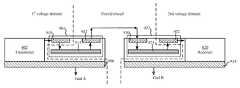
- FIG. 1shows a system for galvanic isolation between transmitter and receiver circuits operating in different voltage domains.
- a transmitter circuit 102operates in a first voltage domain and a receiver circuit 110 operates in a second voltage domain.
- Isolation circuit 104provides a communication signal path between the transmitter 102 and receiver 110 while providing galvanic isolation between the two circuits.
- the isolation circuit 104includes two capacitive structures 106 and 108 .
- the isolation circuit 104is configured to receive data signals from the transmitter 102 .
- the received data signalscan be referenced to the first voltage domain (e.g., reference to a ground).
- the data signalsare eventually received at the receiver circuit 110 ; however, receiver circuit 110 operates in a second voltage domain, (e.g., with reference to a second ground).
- Intermediate nodes of the isolation circuite.g., nodes between circuits 106 and 108 , may be floating voltages that are not referenced to the ground voltage of either voltage domain.
- the capacitive structures of the isolation circuit 104may be implemented on the same or different substrates of the system.
- the first capacitive structure 106may be integrated with the transmitter 102 on a first IC and the second capacitive structure 108 may be integrated with the receiver on a second IC.
- the first and second capacitive structures 106 and 108each include a respective set of three capacitive plates (e.g., 107 and 109 ), which are arranged to function as two series-connected capacitors.
- each capacitive structurecan include a set of three capacitive plates: a first/input plate, a second/intermediate plate, and a third/output plate.
- the input and output platescan each be configured to function as a respective a capacitor with the intermediate plate acting as the other plate of the respective capacitor.
- the second capacitive structure 108also includes a set of three capacitive plates (e.g., fourth, fifth, and sixth capacitive plates) 109 arranged to function as two capacitors connected in series.
- the fourth and fifth capacitive platese.g., second input and intermediate capacitive plates
- the sixth capacitive platee.g., the second output capacitive plate
- the third and fourth capacitive platesare connected by a conductor that provides a current path, e.g., a bondwire between the first and second capacitive structures.
- FIGS. 2 and 3show a capacitive structure formed on a conductive substrate in accordance with one or more embodiments of the present disclosure.
- FIG. 2shows a top view of a capacitive structure in accordance with one or more embodiments.
- the capacitive structure 200may be used, e.g., to implement capacitive structures 106 and 108 in FIG. 1 .
- FIG. 3shows a cross section A of the capacitive structure shown in FIG. 2 , in accordance with one or more embodiments.
- the capacitive structureincludes three capacitive plates arranged to function as two series coupled capacitors.
- the capacitive structureincludes capacitive plates 212 and 216 (i.e., input and output capacitive plates) located in an upper layer and a capacitive plate 214 (i.e., intermediate capacitive plate) located below capacitive plates 212 and 216 in a lower layer.
- Capacitive plates 212 and 214form a first capacitor that is connected in series by plate 214 with a second capacitor formed by capacitive plates 214 and 216 .
- a first layer of dielectric material 218separates the capacitive plate 214 from each of capacitive plates 212 and 216 .
- Thickness d 1 of the dielectric 218determines the vertical breakdown voltage of the capacitors.
- the series-coupled arrangementallows overall breakdown voltage (i.e., V Max between 220 and 222 ) to be double the breakdown voltage typically provided by a typical two plate capacitor having the same thickness d 1 of dielectric material.
- Embodiments of the present disclosureare directed toward an isolation circuit having a first capacitive structure 200 in a first voltage domain.
- the first capacitive structurecan include a first conducting substrate 210 that is electrically connected to a reference voltage of the first voltage domain, such as ground.
- the substrate 210may also have active CMOS components (e.g., transistors) that require that conductive substrate to be connected to ground.
- a first dielectric layer, having a thickness d 1defines/provides a breakdown voltage by way of the physical separation between the intermediate capacitor plate 214 and each of the input 212 and output 216 capacitor plates.
- a second dielectric layer, having a thickness d 2is configured and arranged to provide substantially the same breakdown voltage as the first breakdown voltage.
- the two dielectric layerscan be part of the same dielectric material, they are referred to as different layers due to their respective relationships between the respective plates and/or conductive substrate.
- the above arrangement of platescan then be repeated for a second capacitive structure in a second voltage domain.
- capacitive plate 212has an area A 1 and the capacitive plate 216 has an area A 2 .
- V B(V max /2).
- V maxD*E bd
- V max2* d 1* E bd ⁇ D*E bd
- V maxD*E bd
- E bdis the breakdown field
- d 1is the distance between capacitive plate 214 and capacitive plates 212 and 216
- d 1 maxD ⁇ d 2 min
- a capacitive structureis formed on a silicon-on-insulator (SOI) substrate.
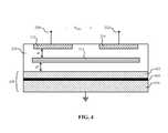
- FIG. 4shows a cross section A of the capacitive structure shown in FIG. 2 formed on an SOI substrate, in accordance with one or more embodiments.
- the cross section shown in FIG. 4is similar to the cross section shown in FIG. 3 in many respects.
- reference numbers of FIG. 3are used to describe similar aspects.
- the SOI substrate 430includes a handle wafer 436 , a silicon layer 432 , and a buried oxide layer 434 providing isolation between the handle wafer the silicon layer.
- the breakdown voltagemay be further improved using the buried oxide layer 434 to provide additional isolation between plate 214 and the handle wafer 436 , which is tied to a ground voltage.
- the buried oxideadds to the effective dielectric thickness below plate 214 .
- d 2can be reduced and d 1 increased to further increase the breakdown voltage of the capacitive structure.
- the breakdown voltagecan be improved with respect to the design in FIG. 3 by a factor (D+d_box)/D.
- SOI processmay form the dielectric 218 from several different dielectric layers having different dielectric constants and, thus, different breakdown fields.
- the bottom electrodemight be made in the silicon of the SOI or in a conducting layer above it.
- the thickness d 2is the sum of the thicknesses of all dielectrics below the lower capacitive plate 214
- d 1is the sum of the thicknesses of all dielectric layers between the lower capacitive plate 214 and the upper capacitive plates 212 and 216 .
- the breakdownoccurs first in the dielectric layer having the smallest breakdown field.
- E bd,1is the breakdown field of dielectric layer above plate 214 having the weakest breakdown field
- E 2 bdis breakdown field of dielectric layer above plate 214 that has the weakest breakdown field.
- the silicon layer (e.g., 432 ) of a SOI substratemay be connected to a reference voltage (e.g., ground voltage).
- a reference voltagee.g., ground voltage
- the portion of the silicon layer 432 below the capacitive plate 214may be insulated from the ground voltage.
- FIGS. 5 and 6show a capacitive structure with an oxide ring 502 provided to insulate the portion of the silicon layer of the SOI substrate from the ground voltage.
- FIG. 5shows a top view of the capacitive structure in accordance with one or more embodiments.
- the capacitive structure 500may be used, e.g., to implement capacitive structures 106 and 108 in FIG. 1 .
- FIG. 6shows a cross section B of the capacitive structure shown in FIG. 5 , in accordance with one or more embodiments.
- the capacitive structure shown in FIGS. 5 and 6is similar to the capacitive structure shown in FIGS. 2 and 4 in many respects. For ease of explanation, reference numbers of FIGS. 2 and 4 are used to describe similar aspects.
- the oxide ring 502As a result of the oxide ring 502 , the voltage of the insulated portion of the silicon layer is floating with respect to the ground voltage.
- the oxide ring 502may be implemented in some embodiments using medium trench isolation (MTI). To fully utilize the isolation of the oxide layer 434 , the breakdown strength of the oxide ring 502 should be greater than or equal to that of the oxide layer 434 . In some implementations, the oxide ring 502 may be implemented using multiple concentric oxide rings.
- MTImedium trench isolation
- Some applicationsmay require breakdown voltages greater than those achieved by the above capacitive structures. It is recognized that multiple capacitive structures may be implemented on one or more substrates and connected together in series to increase the overall breakdown voltage. In such arrangements, the breakdown voltage between the endpoint contacts of the series coupled capacitive structures is equal to the sum of the individual breakdown voltages (V_Total Max ) of the capacitive structures so connected.
- FIG. 7shows three series-connected capacitive structures located on separate substrates, consistent with one or more embodiments.
- the three capacitive structuresare similar in structure and operation to the cross section of the capacitive structure 200 shown in FIG. 3 .
- Substrates 710 , 720 , and 740correspond to substrate 210
- dielectrics 718 , 728 , and 748correspond to dielectric 218 .
- Capacitive plates 712 , 722 , and 742each correspond to capacitive plate 212 shown in FIG. 3 .
- capacitive plates 714 , 724 , and 744each correspond to capacitive plate 214
- capacitive plates 716 , 726 , and 746each correspond to capacitive plate 216 .
- the three capacitive structuresare connected together in series to provide a series coupled capacitance.
- the connections between pads 716 and 722can, for example, be made using bondwires. This can be particularly useful for providing a large breakdown voltage V_Total max between nodes 760 and 762 , relative to a single capacitive structure (e.g., V 1 max ).
- the substrates 710 , 720 and 740can be tied to a reference voltage, such as ground, as shown in FIG. 7 .
- a reference voltagesuch as ground
- various types of digital circuitrycan require, or otherwise benefit from, a grounded substrate.
- one or more of the substrates 710 , 720 or 740can be left at a floating voltage potential.
- breakdown voltage between the intermediate capacitive plate and the substratemay be less of a concern (e.g., due to the respective voltage differentials that may then occur between an intermediate plate and the substrate).
- the overall breakdown voltagemay be increased by increasing the dielectric thickness d 1 relative to the dielectric thickness d 2 .
- FIG. 8shows a method for manufacture of a capacitive structure consistent with one or more embodiments.
- An SOI substrateis provided at block 802 .
- an isolation ringmay be formed at block 804 by forming an oxide ring (e.g., 502 ) in a top silicon layer (e.g., 230 ) of the SOI substrate.
- the oxide ringmay be formed using medium trench isolation (MTI).
- MTImedium trench isolation
- the addition of the isolation trenchcan be used to insulate a portion of the silicon layer that is floating with respect to a ground voltage.
- a lower dielectric layer(e.g., the dielectric layer having thickness d 2 ) is formed over the SOI substrate at block 806 .
- An intermediate capacitive plateis formed on the dielectric layer at block 808 .
- An upper dielectric layer(e.g., the dielectric layer having thickness d 1 ) is formed on the intermediate capacitive plate at block 810 .
- Input and output capacitive plates(e.g., 212 and 216 ) are formed on the upper dielectric layer at block 812 .
- the lower dielectric layerseparates the SOI substrate from the intermediate capacitive plate by a distance (e.g. d 2 ) that influences the breakdown voltage between the capacitive plate and the SOI substrate.
- the upper dielectric layerseparates each of the input and output capacitive plates (e.g., 212 and 216 ) from the intermediate capacitive plate (e.g., 214 ) by a distance (e.g., d 1 ) that influences the breakdown voltage between the intermediate capacitive plate and the input or output capacitive plates.
- the overall breakdown voltage of the capacitive structureis determined by the smaller of the two breakdown voltages through the respective first and second dielectric layers.
- One or more embodimentsadjust the overall breakdown voltage by configuring the respective thicknesses d 1 and d 2 of the dielectric layers, such that the first and second breakdown voltages are (substantially) equal.
- the breakdown voltagesare substantially equal relative to the desired application.
- the breakdown voltagesmay vary depending upon the manufacturing processes. In such instances, the precise breakdown voltages can vary from device to device. The breakdown voltage, however, is still substantially equal despite such manufacturing variations. In another instance, minor differences in the breakdown voltages are possible such that the overall breakdown voltage of the device or structure is within an acceptable margin relative to having identical breakdown voltages (e.g., 5%).
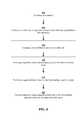
- FIG. 9illustrates a method of communication between first and second voltage domains, consistent with one or more embodiments.
- Communication signalsare transmitted from a transmitter circuit 902 located on a first substrate 906 that is in a first voltage domain.
- Capacitive isolationis provided for the communication signals between the first voltage domain and a second voltage domain by communicating the transmitted communication signals through an isolation circuit that includes a first capacitive structure 904 located on the first substrate 906 to provide the communication signal from the first voltage domain to an unreferenced voltage domain.
- a second capacitive structure 922 located on a second substrate 924is used to provide the communication signals from the unreferenced voltage domain to a second voltage domain.
- a receiver circuit 920is located on the second substrate and is configured to receive the communication signals at an input in the second voltage domain from the second capacitive structure 922 .
- capacitive structures 904 and 922 illustrated in FIG. 9are each structurally and operationally similar to the capacitive structure discussed, for instance, with reference to FIGS. 2 and 3 .
- capacitive structure 904includes three capacitive plates 910 , 912 , and 914 , which are configured and arranged in a similar manner as capacitive plates 212 , 214 , and 216 .
- capacitive structure 904includes three capacitive plates 930 , 934 , and 932 , which are configured and arranged in a similar manner as capacitive plates 212 , 214 , and 216 .
- Capacitive plate 910is configured to receive the communication signals from the transmitter 902 in the first voltage domain.
- the communication signalsare capacitively communicated (using capacitive coupling between plates of the capacitor) from the plate 910 to plate 914 , which operates as a floating node in the unreferenced voltage domain.
- the communication signalsare capacitively communicated from plate 914 to plate 912 , which operates as a second floating node in the unreferenced voltage domain.
- the communication signalsare passed from plate 912 to plate 930 , which operates as a third floating node in the unreferenced voltage domain.
- the communication signalsare capacitively communicated from the plate 912 to plate 930 with operates as a third floating node in the unreferenced voltage domain.
- the communication signalsare capacitively communicated from the plate 930 to plate 934 , which operates as a fourth floating node in the unreferenced voltage domain.
- the communication signalsare capacitively communicated from the plate 934 to plate 932 , which operates as in the second voltage domain.
- the receiver 920is receives the communication signals in the second voltage domain from capacitive plate 932 .
- Certain embodimentsare directed toward controlling the breakdown voltage by designing the different capacitive plates to have different sizes and/or shapes. For instance, it has been recognized that the electric field can be strongest near the edge of a capacitive plate and or at a corner of a capacitive plate. Accordingly, the breakdown voltage is sometimes limited by the electric field strength at such locations (where it is the strongest). Accordingly, embodiments contemplate offsetting the edges of the respective plates from one another (relative to a horizontal/lateral position). For instance, the intermediate (bottom) capacitive plate can be configured to extend beyond the edges of each of the input and output (upper) capacitive plates.
- one or more embodimentscan use different coding techniques and different types of circuits communicating data through the isolation region.
- the data communicationscan use analog, digital, RF, serial and/or parallel communication techniques.
- different types of modulation schemescan be used for carrying information across the isolation region, including but not limited to OOK (on-off keying), amplitude, phase-based and/or frequency-based.
- communicationscan be carried out between multiple circuits placed within a single chip-package (e.g., BGA package) and also having galvanic isolation there between.
- the communicationscan be carried out between multi-chip modules (MCM) having multiple integrated circuits (ICs), semiconductor dies or other discrete components contained within a common housing.
- MCMmulti-chip modules
- part of the signals reaching the receivercan be used for powering the IC, or waking it up out of a low-power mode.
- the various communicationscan be carried out using different isolation buffer circuits and amplifiers.
- Various applicationsare also contemplated, including but not limited to applications in which small voltage differences exist between transmitters and receivers, and applications in which large voltages can exist (e.g., hundreds of volts as can be used in automotive applications where electric motors are used in place of (or in combination with) combustion engines). Consistent with one or more embodiments discussed herein, U.S. Pat. No. 6,920,576 (filed May 31, 2001; Ehmann, Gregory E.), U.S. Pat. No. 6,882,046 (filed Dec.
Landscapes
- Engineering & Computer Science (AREA)
- Power Engineering (AREA)
- Microelectronics & Electronic Packaging (AREA)
- Physics & Mathematics (AREA)
- Condensed Matter Physics & Semiconductors (AREA)
- General Physics & Mathematics (AREA)
- Computer Hardware Design (AREA)
- Manufacturing & Machinery (AREA)
- Computer Networks & Wireless Communication (AREA)
- Signal Processing (AREA)
- Semiconductor Integrated Circuits (AREA)
Abstract
Description
VMax−VB=VMax/2>d1*Ebd.
Second, breakdown occurs between
VB=VMax/2>d2*Ebd.
Dielectric layers thicknesses d1and d2are selected to maximize VMaxwithout exceeding the above breakdown limits.
d2=D−d1.
where d2is the distance between the
Ford1≧d2:Vmax=D*Ebd
Ford1<d2:Vmax=2*d1*Ebd<D*Ebd
Accordingly, when d1≧d2, there is a larger overall breakdown voltage than when d1<d2. However, larger dielectric thicknesses d1 can result in a decrease in capacitance. In some particular embodiments, the thicknesses of the first and second dielectric layers are therefore substantially equal (d1=d2). For d1≧d2:
Vmax=D*Ebd
where D=d1+d2 is the total dielectric thickness, Ebdis the breakdown field, d1 is the distance between
d1*E1bd=d2*E2bd.
where Ebd,1is the breakdown field of dielectric layer above
Claims (23)
Priority Applications (4)
| Application Number | Priority Date | Filing Date | Title |
|---|---|---|---|
| US13/478,737US9007141B2 (en) | 2012-05-23 | 2012-05-23 | Interface for communication between voltage domains |
| EP13163170.7AEP2674975B1 (en) | 2012-05-23 | 2013-04-10 | Interface for communication between voltage domains |
| CN201310181934.5ACN103427865B (en) | 2012-05-23 | 2013-05-16 | Interface for communication between voltage domains |
| US14/657,978US9431177B2 (en) | 2012-05-23 | 2015-03-13 | Interface for communication between voltage domains |
Applications Claiming Priority (1)
| Application Number | Priority Date | Filing Date | Title |
|---|---|---|---|
| US13/478,737US9007141B2 (en) | 2012-05-23 | 2012-05-23 | Interface for communication between voltage domains |
Related Child Applications (1)
| Application Number | Title | Priority Date | Filing Date |
|---|---|---|---|
| US14/657,978ContinuationUS9431177B2 (en) | 2012-05-23 | 2015-03-13 | Interface for communication between voltage domains |
Publications (2)
| Publication Number | Publication Date |
|---|---|
| US20130316646A1 US20130316646A1 (en) | 2013-11-28 |
| US9007141B2true US9007141B2 (en) | 2015-04-14 |
Family
ID=48143450
Family Applications (2)
| Application Number | Title | Priority Date | Filing Date |
|---|---|---|---|
| US13/478,737Active2033-11-30US9007141B2 (en) | 2012-05-23 | 2012-05-23 | Interface for communication between voltage domains |
| US14/657,978ActiveUS9431177B2 (en) | 2012-05-23 | 2015-03-13 | Interface for communication between voltage domains |
Family Applications After (1)
| Application Number | Title | Priority Date | Filing Date |
|---|---|---|---|
| US14/657,978ActiveUS9431177B2 (en) | 2012-05-23 | 2015-03-13 | Interface for communication between voltage domains |
Country Status (3)
| Country | Link |
|---|---|
| US (2) | US9007141B2 (en) |
| EP (1) | EP2674975B1 (en) |
| CN (1) | CN103427865B (en) |
Cited By (4)
| Publication number | Priority date | Publication date | Assignee | Title |
|---|---|---|---|---|
| US20150187503A1 (en)* | 2012-05-23 | 2015-07-02 | Nxp B.V. | Interface for communication between voltage domains |
| US9520354B1 (en) | 2015-07-29 | 2016-12-13 | Avago Technologies General Ip (Singapore) Pte. Ltd. | Silicon designs for high voltage isolation |
| US11476045B2 (en) | 2020-05-29 | 2022-10-18 | Analog Devices International Unlimited Company | Electric field grading protection design surrounding a galvanic or capacitive isolator |
| US11711894B1 (en) | 2022-02-03 | 2023-07-25 | Analog Devices International Unlimited Company | Capacitively coupled resonators for high frequency galvanic isolators |
Families Citing this family (11)
| Publication number | Priority date | Publication date | Assignee | Title |
|---|---|---|---|---|
| US9735112B2 (en)* | 2014-01-10 | 2017-08-15 | Fairchild Semiconductor Corporation | Isolation between semiconductor components |
| US9673271B2 (en)* | 2015-10-12 | 2017-06-06 | Qorvo Us, Inc. | Adaptive capacitors with reduced variation in value and in-line methods for making same |
| US10074713B1 (en)* | 2017-09-15 | 2018-09-11 | Allegro Microsystems, Llc | Signal isolator integrated circuit package |
| CN107799519A (en)* | 2017-11-20 | 2018-03-13 | 荣湃半导体(上海)有限公司 | A kind of high_voltage isolation circuit |
| FR3091004B1 (en)* | 2018-12-24 | 2020-12-04 | Soitec Silicon On Insulator | SEMICONDUCTOR TYPE STRUCTURE FOR DIGITAL AND RADIO FREQUENCY APPLICATIONS |
| US20210057330A1 (en)* | 2019-08-22 | 2021-02-25 | Allegro Microsystems, Llc | Single chip signal isolator |
| CN114556553A (en)* | 2019-10-29 | 2022-05-27 | 华为技术有限公司 | Semiconductor device and manufacturing method thereof |
| CN111312897B (en)* | 2020-02-28 | 2023-10-10 | 思瑞浦微电子科技(苏州)股份有限公司 | Isolation capacitor and isolation circuit |
| US11515246B2 (en) | 2020-10-09 | 2022-11-29 | Allegro Microsystems, Llc | Dual circuit digital isolator |
| WO2022266505A1 (en)* | 2021-06-18 | 2022-12-22 | Nunami Inc. | Devices, systems, and methods for serial communication over a galvanically isolated channel |
| US12347753B2 (en)* | 2021-09-13 | 2025-07-01 | Nxp Usa, Inc. | Semiconductor device having galvanic isolation and method therefor |
Citations (71)
| Publication number | Priority date | Publication date | Assignee | Title |
|---|---|---|---|---|
| US3273033A (en) | 1963-08-29 | 1966-09-13 | Litton Systems Inc | Multidielectric thin film capacitors |
| US3512110A (en)* | 1968-05-06 | 1970-05-12 | Motorola Inc | Microstrip-microwave coupler |
| US4292595A (en) | 1979-11-13 | 1981-09-29 | Burr-Brown Research Corporation | Capacitance coupled isolation amplifier and method |
| US4748419A (en) | 1986-04-28 | 1988-05-31 | Burr-Brown Corporation | Isolation amplifier with precise timing of signals coupled across isolation barrier |
| GB2204467A (en) | 1987-04-22 | 1988-11-09 | Silicon Systems Inc | Method and apparatus for generating a data recovery window |
| US4809356A (en)* | 1988-02-08 | 1989-02-28 | Motorola, Inc. | Three-way power splitter using directional couplers |
| US5138436A (en) | 1990-11-16 | 1992-08-11 | Ball Corporation | Interconnect package having means for waveguide transmission of rf signals |
| US5187636A (en) | 1991-07-18 | 1993-02-16 | Rohm Co., Ltd. | Dielectric device |
| US5187637A (en) | 1992-02-14 | 1993-02-16 | At&T Bell Laboratories | Monolithic high-voltage capacitor |
| US5321597A (en) | 1991-03-22 | 1994-06-14 | Gec Alsthom Sa | Galvanic isolation device for direct current electrical signals or electrical signals likely to include a direct current component |
| US5786979A (en)* | 1995-12-18 | 1998-07-28 | Douglass; Barry G. | High density inter-chip connections by electromagnetic coupling |
| US6271131B1 (en) | 1998-08-26 | 2001-08-07 | Micron Technology, Inc. | Methods for forming rhodium-containing layers such as platinum-rhodium barrier layers |
| US6331999B1 (en) | 1998-01-15 | 2001-12-18 | Lsi Logic Corporation | Serial data transceiver architecture and test method for measuring the amount of jitter within a serial data stream |
| US20010052623A1 (en) | 2000-03-30 | 2001-12-20 | Atsushi Kameyama | Semiconductor integrated circuit |
| US6347395B1 (en) | 1998-12-18 | 2002-02-12 | Koninklijke Philips Electronics N.V. (Kpenv) | Method and arrangement for rapid silicon prototyping |
| US20020021144A1 (en) | 2000-07-12 | 2002-02-21 | Morgan Mark W. | Three-volt TIA/EIA-485 driver circuit |
| US6429735B1 (en) | 2001-08-29 | 2002-08-06 | National Semiconductor Corporation | High speed output buffer |
| US20020184544A1 (en) | 2001-05-31 | 2002-12-05 | Ivan Svestka | Parallel data communication consuming low power |
| US20020186058A1 (en) | 2001-05-01 | 2002-12-12 | Prodanov Vladimir I. | Buffer interface architecture |
| US6507226B2 (en) | 2000-07-31 | 2003-01-14 | Intersil Americas Inc. | Power device driving circuit and associated methods |
| EP1291918A2 (en) | 2001-09-06 | 2003-03-12 | Programmable Silicon Solutions | Integrated radio frequency circuits |
| US6636166B2 (en) | 2001-05-31 | 2003-10-21 | Koninklijke Philips Electronics N.V. | Parallel communication based on balanced data-bit encoding |
| US20030214346A1 (en) | 2002-02-25 | 2003-11-20 | Stmicroelectronics S.R.I. | Charge pump for negative voltages |
| US6664859B1 (en) | 2002-09-13 | 2003-12-16 | Faaday Technology Crop. | State machine based phase-lock-loop for USB clock recovery |
| US20040076192A1 (en) | 1999-10-19 | 2004-04-22 | Rambus Inc. | Calibrated data communication system and method |
| US20040159893A1 (en) | 2003-02-14 | 2004-08-19 | Akinao Kitahara | Semiconductor device and method for manufacturing the same |
| US20040161068A1 (en) | 2003-02-11 | 2004-08-19 | Jared Zerbe | Circuit, apparatus and method for adjusting a duty-cycle of a clock signal in response to incoming serial data |
| US6809569B2 (en) | 2002-02-28 | 2004-10-26 | Rambus Inc. | Circuit, apparatus and method having a cross-coupled load with current mirrors |
| CN1551656A (en) | 2003-05-14 | 2004-12-01 | 三星电机株式会社 | Matching circuit and stacked duplexer with same |
| US6839862B2 (en) | 2001-05-31 | 2005-01-04 | Koninklijke Philips Electronics N.V. | Parallel data communication having skew intolerant data groups |
| US6882046B2 (en) | 2001-07-09 | 2005-04-19 | Koninklijke Phillips Electronics N.V. | Single package containing multiple integrated circuit devices |
| US20050127452A1 (en) | 2003-12-05 | 2005-06-16 | Intel Corporation (A Delaware Corporation) | Resistive isolation between a body and a body contact |
| US6920576B2 (en) | 2001-05-31 | 2005-07-19 | Koninklijke Philips Electronics N.V. | Parallel data communication having multiple sync codes |
| US20050174156A1 (en) | 2004-02-05 | 2005-08-11 | Lin Wu | Systems and methods of performing duty cycle control |
| EP1564884A1 (en) | 2002-10-31 | 2005-08-17 | Thine Electronics, Inc. | Differential circuit and receiver with same |
| US20050201025A1 (en) | 2004-03-09 | 2005-09-15 | Jeng-Jye Shau | Capacitor coupling circuits |
| US6992377B2 (en) | 2004-02-26 | 2006-01-31 | Freescale Semiconductor, Inc. | Semiconductor package with crossing conductor assembly and method of manufacture |
| US20060138595A1 (en) | 2002-11-27 | 2006-06-29 | Kabushiki Kaisha Toshiba | Semiconductor device and method of manufacturing the same |
| US7199617B1 (en) | 2004-11-12 | 2007-04-03 | Intel Corporation | Level shifter |
| US20070075784A1 (en) | 2004-02-05 | 2007-04-05 | Ola Pettersson | Radio frequency power amplifier |
| US20070097562A1 (en) | 2004-06-18 | 2007-05-03 | Hiroyuki Shinoda | Communication unit |
| CN101006384A (en) | 2004-08-23 | 2007-07-25 | 皇家飞利浦电子股份有限公司 | Active matrix devices |
| US7302247B2 (en) | 2004-06-03 | 2007-11-27 | Silicon Laboratories Inc. | Spread spectrum isolator |
| CN101118924A (en) | 2006-07-31 | 2008-02-06 | 中国科学院微电子研究所 | A high breakdown voltage silicon-on-insulator device structure and its preparation method |
| US7376212B2 (en) | 2004-06-03 | 2008-05-20 | Silicon Laboratories Inc. | RF isolator with differential input/output |
| US7400173B1 (en) | 2003-09-19 | 2008-07-15 | Cypress Semicondductor Corp. | Differential receiver with wide input common mode range and low duty cycle distortion |
| US20080174360A1 (en) | 2007-01-23 | 2008-07-24 | Etron Technology, Inc. | Charge pump circuit for high voltage generation |
| US7411421B1 (en) | 2005-12-07 | 2008-08-12 | Altera Corporation | Apparatus and method for generating differential signal using single-ended drivers |
| US7421028B2 (en) | 2004-06-03 | 2008-09-02 | Silicon Laboratories Inc. | Transformer isolator for digital power supply |
| US7447492B2 (en) | 2004-06-03 | 2008-11-04 | Silicon Laboratories Inc. | On chip transformer isolator |
| US20080272703A1 (en) | 2007-05-03 | 2008-11-06 | Tpo Displays Corp. | System for displaying image |
| US20080290444A1 (en) | 2007-05-24 | 2008-11-27 | Philip John Crawley | Capacitor structure in a semiconductor device |
| US7460604B2 (en) | 2004-06-03 | 2008-12-02 | Silicon Laboratories Inc. | RF isolator for isolating voltage sensing and gate drivers |
| US7463105B2 (en)* | 2005-05-12 | 2008-12-09 | Sony Corporation | Microresonator, band-pass filter, semiconductor device, and communication apparatus |
| US7466213B2 (en)* | 2003-10-06 | 2008-12-16 | Nxp B.V. | Resonator structure and method of producing it |
| US20090146760A1 (en) | 2006-05-15 | 2009-06-11 | Nxp B.V. | Assembly, chip and method of operating |
| US7577223B2 (en) | 2004-06-03 | 2009-08-18 | Silicon Laboratories Inc. | Multiplexed RF isolator circuit |
| US20090213914A1 (en) | 2004-06-03 | 2009-08-27 | Silicon Laboratories Inc. | Capacitive isolation circuitry |
| US20090237858A1 (en) | 2005-12-22 | 2009-09-24 | Steeneken Peter G | Arrangement of MEMS Devices Having Series Coupled Capacitors |
| US20100052826A1 (en) | 2004-06-03 | 2010-03-04 | Silicon Laboratories Inc. | Isolator with complementary configurable memory |
| US7737871B2 (en) | 2004-06-03 | 2010-06-15 | Silicon Laboratories Inc. | MCU with integrated voltage isolator to provide a galvanic isolation between input and output |
| US7738568B2 (en) | 2004-06-03 | 2010-06-15 | Silicon Laboratories Inc. | Multiplexed RF isolator |
| US7755400B2 (en) | 2008-05-29 | 2010-07-13 | Texas Instruments Incorporated | Systems and methods of digital isolation with AC/DC channel merging |
| US7821428B2 (en) | 2004-06-03 | 2010-10-26 | Silicon Laboratories Inc. | MCU with integrated voltage isolator and integrated galvanically isolated asynchronous serial data link |
| US20100327940A1 (en) | 2009-06-26 | 2010-12-30 | William Richard Eisenstadt | Embedded phase noise measurement system |
| US20110006814A1 (en) | 2009-07-02 | 2011-01-13 | Nxp B.V. | Power stage |
| US7902627B2 (en) | 2004-06-03 | 2011-03-08 | Silicon Laboratories Inc. | Capacitive isolation circuitry with improved common mode detector |
| US8049573B2 (en) | 2004-06-03 | 2011-11-01 | Silicon Laboratories Inc. | Bidirectional multiplexed RF isolator |
| US8169108B2 (en) | 2004-06-03 | 2012-05-01 | Silicon Laboratories Inc. | Capacitive isolator |
| US8284823B2 (en) | 2006-01-03 | 2012-10-09 | Nxp B.V. | Serial data communication system and method |
| US8902016B2 (en)* | 2009-10-21 | 2014-12-02 | Stmicroelectronics S.R.L. | Signal transmission through LC resonant circuits |
Family Cites Families (8)
| Publication number | Priority date | Publication date | Assignee | Title |
|---|---|---|---|---|
| US5008639A (en)* | 1989-09-27 | 1991-04-16 | Pavio Anthony M | Coupler circuit |
| US6023408A (en)* | 1996-04-09 | 2000-02-08 | The Board Of Trustees Of The University Of Arkansas | Floating plate capacitor with extremely wide band low impedance |
| EP1598872A1 (en)* | 2003-02-27 | 2005-11-23 | TDK Corporation | High dielectric constant insulating film, thin-film capacitive element, thin-film multilayer capacitor, and method for manufacturing thin-film capacitive element |
| KR101436115B1 (en)* | 2007-04-27 | 2014-09-01 | 가부시키가이샤 한도오따이 에네루기 켄큐쇼 | Method of manufacturing semiconductor substrate and method of manufacturing semiconductor device |
| US8659149B2 (en)* | 2011-08-09 | 2014-02-25 | National Semiconductor Corporation | Semiconductor structure with galvanic isolation |
| US8674486B2 (en)* | 2011-12-14 | 2014-03-18 | Samsung Electro-Mechanics | Isolation barrier device and methods of use |
| US9007141B2 (en)* | 2012-05-23 | 2015-04-14 | Nxp B.V. | Interface for communication between voltage domains |
| TWI533414B (en)* | 2012-12-28 | 2016-05-11 | 力林科技股份有限公司 | Electrochemical isolation element and method of manufacturing same |
- 2012
- 2012-05-23USUS13/478,737patent/US9007141B2/enactiveActive
- 2013
- 2013-04-10EPEP13163170.7Apatent/EP2674975B1/ennot_activeNot-in-force
- 2013-05-16CNCN201310181934.5Apatent/CN103427865B/ennot_activeExpired - Fee Related
- 2015
- 2015-03-13USUS14/657,978patent/US9431177B2/enactiveActive
Patent Citations (81)
| Publication number | Priority date | Publication date | Assignee | Title |
|---|---|---|---|---|
| US3273033A (en) | 1963-08-29 | 1966-09-13 | Litton Systems Inc | Multidielectric thin film capacitors |
| US3512110A (en)* | 1968-05-06 | 1970-05-12 | Motorola Inc | Microstrip-microwave coupler |
| US4292595A (en) | 1979-11-13 | 1981-09-29 | Burr-Brown Research Corporation | Capacitance coupled isolation amplifier and method |
| US4748419A (en) | 1986-04-28 | 1988-05-31 | Burr-Brown Corporation | Isolation amplifier with precise timing of signals coupled across isolation barrier |
| GB2204467A (en) | 1987-04-22 | 1988-11-09 | Silicon Systems Inc | Method and apparatus for generating a data recovery window |
| US4809356A (en)* | 1988-02-08 | 1989-02-28 | Motorola, Inc. | Three-way power splitter using directional couplers |
| US5138436A (en) | 1990-11-16 | 1992-08-11 | Ball Corporation | Interconnect package having means for waveguide transmission of rf signals |
| US5321597A (en) | 1991-03-22 | 1994-06-14 | Gec Alsthom Sa | Galvanic isolation device for direct current electrical signals or electrical signals likely to include a direct current component |
| US5187636A (en) | 1991-07-18 | 1993-02-16 | Rohm Co., Ltd. | Dielectric device |
| US5187637A (en) | 1992-02-14 | 1993-02-16 | At&T Bell Laboratories | Monolithic high-voltage capacitor |
| US5786979A (en)* | 1995-12-18 | 1998-07-28 | Douglass; Barry G. | High density inter-chip connections by electromagnetic coupling |
| US6331999B1 (en) | 1998-01-15 | 2001-12-18 | Lsi Logic Corporation | Serial data transceiver architecture and test method for measuring the amount of jitter within a serial data stream |
| US6271131B1 (en) | 1998-08-26 | 2001-08-07 | Micron Technology, Inc. | Methods for forming rhodium-containing layers such as platinum-rhodium barrier layers |
| US6347395B1 (en) | 1998-12-18 | 2002-02-12 | Koninklijke Philips Electronics N.V. (Kpenv) | Method and arrangement for rapid silicon prototyping |
| US20040076192A1 (en) | 1999-10-19 | 2004-04-22 | Rambus Inc. | Calibrated data communication system and method |
| US20010052623A1 (en) | 2000-03-30 | 2001-12-20 | Atsushi Kameyama | Semiconductor integrated circuit |
| US20020021144A1 (en) | 2000-07-12 | 2002-02-21 | Morgan Mark W. | Three-volt TIA/EIA-485 driver circuit |
| US6507226B2 (en) | 2000-07-31 | 2003-01-14 | Intersil Americas Inc. | Power device driving circuit and associated methods |
| US20020186058A1 (en) | 2001-05-01 | 2002-12-12 | Prodanov Vladimir I. | Buffer interface architecture |
| US6839862B2 (en) | 2001-05-31 | 2005-01-04 | Koninklijke Philips Electronics N.V. | Parallel data communication having skew intolerant data groups |
| US6636166B2 (en) | 2001-05-31 | 2003-10-21 | Koninklijke Philips Electronics N.V. | Parallel communication based on balanced data-bit encoding |
| US6920576B2 (en) | 2001-05-31 | 2005-07-19 | Koninklijke Philips Electronics N.V. | Parallel data communication having multiple sync codes |
| US20020184544A1 (en) | 2001-05-31 | 2002-12-05 | Ivan Svestka | Parallel data communication consuming low power |
| US6859883B2 (en) | 2001-05-31 | 2005-02-22 | Koninklijke Philips Electronics N.V. | Parallel data communication consuming low power |
| US6882046B2 (en) | 2001-07-09 | 2005-04-19 | Koninklijke Phillips Electronics N.V. | Single package containing multiple integrated circuit devices |
| US6429735B1 (en) | 2001-08-29 | 2002-08-06 | National Semiconductor Corporation | High speed output buffer |
| EP1291918A2 (en) | 2001-09-06 | 2003-03-12 | Programmable Silicon Solutions | Integrated radio frequency circuits |
| US20030214346A1 (en) | 2002-02-25 | 2003-11-20 | Stmicroelectronics S.R.I. | Charge pump for negative voltages |
| US6809569B2 (en) | 2002-02-28 | 2004-10-26 | Rambus Inc. | Circuit, apparatus and method having a cross-coupled load with current mirrors |
| US6664859B1 (en) | 2002-09-13 | 2003-12-16 | Faaday Technology Crop. | State machine based phase-lock-loop for USB clock recovery |
| EP1564884A1 (en) | 2002-10-31 | 2005-08-17 | Thine Electronics, Inc. | Differential circuit and receiver with same |
| US20060138595A1 (en) | 2002-11-27 | 2006-06-29 | Kabushiki Kaisha Toshiba | Semiconductor device and method of manufacturing the same |
| US20040161068A1 (en) | 2003-02-11 | 2004-08-19 | Jared Zerbe | Circuit, apparatus and method for adjusting a duty-cycle of a clock signal in response to incoming serial data |
| US20040159893A1 (en) | 2003-02-14 | 2004-08-19 | Akinao Kitahara | Semiconductor device and method for manufacturing the same |
| CN1551656A (en) | 2003-05-14 | 2004-12-01 | 三星电机株式会社 | Matching circuit and stacked duplexer with same |
| US6885259B2 (en) | 2003-05-14 | 2005-04-26 | Samsung Electro-Mechanics Co., Ltd. | Matching circuit and laminated duplexer with the matching circuit |
| US7400173B1 (en) | 2003-09-19 | 2008-07-15 | Cypress Semicondductor Corp. | Differential receiver with wide input common mode range and low duty cycle distortion |
| US7466213B2 (en)* | 2003-10-06 | 2008-12-16 | Nxp B.V. | Resonator structure and method of producing it |
| US20050127452A1 (en) | 2003-12-05 | 2005-06-16 | Intel Corporation (A Delaware Corporation) | Resistive isolation between a body and a body contact |
| US20070075784A1 (en) | 2004-02-05 | 2007-04-05 | Ola Pettersson | Radio frequency power amplifier |
| US20050174156A1 (en) | 2004-02-05 | 2005-08-11 | Lin Wu | Systems and methods of performing duty cycle control |
| US6992377B2 (en) | 2004-02-26 | 2006-01-31 | Freescale Semiconductor, Inc. | Semiconductor package with crossing conductor assembly and method of manufacture |
| US20050201025A1 (en) | 2004-03-09 | 2005-09-15 | Jeng-Jye Shau | Capacitor coupling circuits |
| US20090213914A1 (en) | 2004-06-03 | 2009-08-27 | Silicon Laboratories Inc. | Capacitive isolation circuitry |
| US7856219B2 (en) | 2004-06-03 | 2010-12-21 | Silicon Laboratories Inc. | Transformer coils for providing voltage isolation |
| US8198951B2 (en)* | 2004-06-03 | 2012-06-12 | Silicon Laboratories Inc. | Capacitive isolation circuitry |
| US7376212B2 (en) | 2004-06-03 | 2008-05-20 | Silicon Laboratories Inc. | RF isolator with differential input/output |
| US8169108B2 (en) | 2004-06-03 | 2012-05-01 | Silicon Laboratories Inc. | Capacitive isolator |
| US8064872B2 (en) | 2004-06-03 | 2011-11-22 | Silicon Laboratories Inc. | On chip transformer isolator |
| US8049573B2 (en) | 2004-06-03 | 2011-11-01 | Silicon Laboratories Inc. | Bidirectional multiplexed RF isolator |
| US7421028B2 (en) | 2004-06-03 | 2008-09-02 | Silicon Laboratories Inc. | Transformer isolator for digital power supply |
| US7447492B2 (en) | 2004-06-03 | 2008-11-04 | Silicon Laboratories Inc. | On chip transformer isolator |
| US20100052826A1 (en) | 2004-06-03 | 2010-03-04 | Silicon Laboratories Inc. | Isolator with complementary configurable memory |
| US7902627B2 (en) | 2004-06-03 | 2011-03-08 | Silicon Laboratories Inc. | Capacitive isolation circuitry with improved common mode detector |
| US7460604B2 (en) | 2004-06-03 | 2008-12-02 | Silicon Laboratories Inc. | RF isolator for isolating voltage sensing and gate drivers |
| US7821428B2 (en) | 2004-06-03 | 2010-10-26 | Silicon Laboratories Inc. | MCU with integrated voltage isolator and integrated galvanically isolated asynchronous serial data link |
| US7738568B2 (en) | 2004-06-03 | 2010-06-15 | Silicon Laboratories Inc. | Multiplexed RF isolator |
| US7737871B2 (en) | 2004-06-03 | 2010-06-15 | Silicon Laboratories Inc. | MCU with integrated voltage isolator to provide a galvanic isolation between input and output |
| US20100118918A1 (en) | 2004-06-03 | 2010-05-13 | Silicon Laboratories Inc. | Spread spectrum isolator |
| US7577223B2 (en) | 2004-06-03 | 2009-08-18 | Silicon Laboratories Inc. | Multiplexed RF isolator circuit |
| US7650130B2 (en) | 2004-06-03 | 2010-01-19 | Silicon Laboratories Inc. | Spread spectrum isolator |
| US7302247B2 (en) | 2004-06-03 | 2007-11-27 | Silicon Laboratories Inc. | Spread spectrum isolator |
| US20070097562A1 (en) | 2004-06-18 | 2007-05-03 | Hiroyuki Shinoda | Communication unit |
| US20090027328A1 (en) | 2004-08-23 | 2009-01-29 | Koninklijke Philips Electronics, N.V. | Active matrix devices |
| CN101006384A (en) | 2004-08-23 | 2007-07-25 | 皇家飞利浦电子股份有限公司 | Active matrix devices |
| US7199617B1 (en) | 2004-11-12 | 2007-04-03 | Intel Corporation | Level shifter |
| US7463105B2 (en)* | 2005-05-12 | 2008-12-09 | Sony Corporation | Microresonator, band-pass filter, semiconductor device, and communication apparatus |
| US7411421B1 (en) | 2005-12-07 | 2008-08-12 | Altera Corporation | Apparatus and method for generating differential signal using single-ended drivers |
| US20090237858A1 (en) | 2005-12-22 | 2009-09-24 | Steeneken Peter G | Arrangement of MEMS Devices Having Series Coupled Capacitors |
| US8284823B2 (en) | 2006-01-03 | 2012-10-09 | Nxp B.V. | Serial data communication system and method |
| US20090146760A1 (en) | 2006-05-15 | 2009-06-11 | Nxp B.V. | Assembly, chip and method of operating |
| CN101118924A (en) | 2006-07-31 | 2008-02-06 | 中国科学院微电子研究所 | A high breakdown voltage silicon-on-insulator device structure and its preparation method |
| US20080174360A1 (en) | 2007-01-23 | 2008-07-24 | Etron Technology, Inc. | Charge pump circuit for high voltage generation |
| US20080272703A1 (en) | 2007-05-03 | 2008-11-06 | Tpo Displays Corp. | System for displaying image |
| US7732889B2 (en) | 2007-05-24 | 2010-06-08 | Akros Silicon Inc. | Capacitor structure in a semiconductor device |
| US20080290444A1 (en) | 2007-05-24 | 2008-11-27 | Philip John Crawley | Capacitor structure in a semiconductor device |
| US7755400B2 (en) | 2008-05-29 | 2010-07-13 | Texas Instruments Incorporated | Systems and methods of digital isolation with AC/DC channel merging |
| CN101877683A (en) | 2009-03-30 | 2010-11-03 | 硅谷实验室公司 | Capacitive isolation circuitry |
| US20100327940A1 (en) | 2009-06-26 | 2010-12-30 | William Richard Eisenstadt | Embedded phase noise measurement system |
| US20110006814A1 (en) | 2009-07-02 | 2011-01-13 | Nxp B.V. | Power stage |
| US8902016B2 (en)* | 2009-10-21 | 2014-12-02 | Stmicroelectronics S.R.L. | Signal transmission through LC resonant circuits |
Non-Patent Citations (30)
| Title |
|---|
| Abedinpour S., Bakkoglu B., with Integrated Output Filter in 0.18 m SiGe Process", IEEE Kiaei S.,"A Multistage Interleaved Synchronous Buck Converter Transactions on Power Electronics, vol. 22, No. 6, Nov. 2007. |
| Adrian Paskins, "The IEEE 1394 BUS", The Institution of Electrical Engineers Conference, May 12, 1997. |
| Aoki I., Kee S., Magoon R., Aparicio R., Bohn F., Zachan J., Hatcher G., McClymont D., Hajimiri A., "A Fully Integrated Quad-Band GSM/GPRS CMOS Power Amplifier", International Solid-State Circuits Conference, 2007. |
| Burr Brown, An error analysis of the ISO102 in a small signal measuring application, Application Bulletin, Burr Brown Corporation, 1994. |
| Burr Brown, Hybrid Isolation Amps Zap Price and Voltage Barriers, Application Bulletin, Burr Brown Corporation, 1994. |
| Burr Brown, ISO 102, ISO 106 Signal Isolation Buffer Amplifiers, Datasheet, Burr Brown Corporation, 1995. |
| Burr Brown, ISO 103, Low Cost, Internally Powered Isolation Amplifier, IC Publication Datasheet, Burr Brown Corporation, 1989. |
| Burr Brown, Noise Sources in Applications Using Capacitive Coupled Isolated Amplifiers, Application Bulletin, Burr Brown Corporation, 1993. |
| Eugenio Culurciello, et al., "Capacitive inter-chip data and power transfer for 3-D VLSI" IEEE Trans. Circuits Syst. II, vol. 53, No. 12, pp. 1348-1352, 2006. |
| Extended European search report in European Patent Appln. No. 13163170.7, 7 pgs. (Jul. 10, 2013). |
| Geoffrey Marcus, et al., "A Monolithic Isolation Amplifier in silicon-on-isolator CMOS: Testing and Applications", Analog Integr. Circ. Sig. Process, Jun. 27, 2006. |
| Greg Smith, "Hybrid Isolation Amps Zap Price and Voltage Barriers" Electronic Design, Dec. 11, 1986, pp. 91-?. |
| Infineon Technologies, IVAX Integrated Voice & ADSL Transceiver, PEB35512, PEB55508, PEB3558, PEB4565, PEB4566, Datasheet, Infineon Technologies AG, 2001. |
| Inoue, A., et al "A high efficiency, high voltage, balanced cascode FET", IEEE International Microwave Symposium, Jun. 1995. |
| J. Basilio Simoes, et al., "The Optical Coupling of Analog Signals" IEEE Transaction on Nuclear Science, vol. 43, No. 3, Jun. 1996, pp. 1672-1674. |
| Kursun V., Narendra S.G., De V.K., Friedman E.G., "High input voltage step-down DC-DC converters for integration in a low voltage CMOS process", Quality Electronic Design, 2004. |
| Lantronix, Xpress-DR+Wireless, Datasheet, LANTRONIX, 2006. |
| phyCORE-MCF548x Hardware Manual, PHYTEC Technology Holding Company, Jan. 2005. |
| Richard Crisp, "Direct Rambus Technology: The New Main Memory Standard" IEEE Micro, Nov./Dec. 1997, pp. 18-28. |
| Rocha J., Santos M., Dores Costa J.M., Lima F., "High Voltage Tolerant Level Shifters and DCVSL in Standard Low Voltage CMOS Technologies", IEEE, 2007. |
| S. M. Sze, "Semiconductor Devices Physics and Technology", 2nd Edition, John Wiley and Sons, Inc., pp. 493-494 and 503-507, 1985, 2002. |
| Scott Irwin, XILINX, "Usage Models for multi-gigabit serial transceivers", WP157, V.1.0, Mar. 15, 2002. |
| Scott Wayne, "Finding the Needle in a Haystack: Measuring Small differential voltages in the presence of large-common mode voltages", Analog Dialogue, 34-1, 2000, pp. 1-4. |
| Sonsky J., Heringa A., Perez-Gonzalez J., Benson J., Chiang P.Y., Bardy S., Volokhine I."Innovative High Voltage transistors for complex HV/RF SoCs in baseline CMOS", IEEE, 2008. |
| Stephen L. Diamond, "IEEE 1394: Status and growth path", IEEE Micro, Jun. 1996, pp. 75-78. |
| Stephen Mick, et al., "Packaging Technology for AC Coupled Interconnection", IEEE Flip-Chip Conference, 2002. |
| Thaddeus J. Gabara, et al., "Capacitive coupling and quantized feedback applied to conventional CMOS technology" IEEE Journal of Solid-State Circuits, vol. 32, No. 3, Mar. 1997. |
| Thomas Nilsson, "A distributed combined heat and power plant control unit", Master Thesis, Linköping Institute of Technology, Dec. 16, 1997. |
| Wally Meinel, et al., "Hermetic Analog Isolation Amplifier", Proceedings of the 1987 International Symposium on Microelectronics, Minneapolis, Sep. 1987. |
| William B. Kuhn, et al., "An RF-based IEEE 1394 Ground Isolator designed in silicon-on-insulator process" Circuits and Systems, 2001. MWSCAS 2001. Proceedings of the 44th IEEE 2001 Midwest Symposium on ,vol. 2 , Aug. 14-17, 2001. |
Cited By (6)
| Publication number | Priority date | Publication date | Assignee | Title |
|---|---|---|---|---|
| US20150187503A1 (en)* | 2012-05-23 | 2015-07-02 | Nxp B.V. | Interface for communication between voltage domains |
| US9431177B2 (en)* | 2012-05-23 | 2016-08-30 | Nxp B.V. | Interface for communication between voltage domains |
| US9520354B1 (en) | 2015-07-29 | 2016-12-13 | Avago Technologies General Ip (Singapore) Pte. Ltd. | Silicon designs for high voltage isolation |
| US11476045B2 (en) | 2020-05-29 | 2022-10-18 | Analog Devices International Unlimited Company | Electric field grading protection design surrounding a galvanic or capacitive isolator |
| US11798741B2 (en) | 2020-05-29 | 2023-10-24 | Analog Devices International Unlimited Company | Electric field grading protection design surrounding a galvanic or capacitive isolator |
| US11711894B1 (en) | 2022-02-03 | 2023-07-25 | Analog Devices International Unlimited Company | Capacitively coupled resonators for high frequency galvanic isolators |
Also Published As
| Publication number | Publication date |
|---|---|
| EP2674975A1 (en) | 2013-12-18 |
| US9431177B2 (en) | 2016-08-30 |
| US20150187503A1 (en) | 2015-07-02 |
| CN103427865A (en) | 2013-12-04 |
| EP2674975B1 (en) | 2019-01-02 |
| CN103427865B (en) | 2015-06-03 |
| US20130316646A1 (en) | 2013-11-28 |
Similar Documents
| Publication | Publication Date | Title |
|---|---|---|
| US9007141B2 (en) | Interface for communication between voltage domains | |
| US7741896B2 (en) | High voltage drive circuit employing capacitive signal coupling and associated devices and methods | |
| JP5255583B2 (en) | High voltage isolated dual capacitor communication system | |
| US10529796B2 (en) | Galvanic isolation device | |
| US8319573B2 (en) | Signal transmission arrangement | |
| CN109787659B (en) | Galvanic isolator | |
| US20150002229A1 (en) | Semiconductor packages having wire bond wall to reduce coupling | |
| US10074713B1 (en) | Signal isolator integrated circuit package | |
| EP3748863B1 (en) | Signal isolator having at least one isolation island | |
| CN1104373A (en) | Interconnection structure for crosstalk reduction toimprove off-chip selectivity | |
| EP3783646A2 (en) | Single chip signal isolator | |
| US7741935B2 (en) | High voltage isolation semiconductor capacitor digital communication device and corresponding package | |
| GB2407207A (en) | Capacitively coupled chip to chip signalling interface | |
| US8818265B2 (en) | Interface for communication between voltage domains | |
| CN116505498A (en) | Radio Frequency Integrated Circuit Devices | |
| CN111326496A (en) | Isolation capacitor and isolation circuit | |
| US11515246B2 (en) | Dual circuit digital isolator | |
| US9209091B1 (en) | Integrated monolithic galvanic isolator | |
| KR102005657B1 (en) | Apparatus and method for low loss coupling capacitors | |
| US20220209750A1 (en) | Quality factor of a parasitic capacitance | |
| US20250309151A1 (en) | High-cmti isolator link design and related methods | |
| CN220963342U (en) | Capacitor unit, filter circuit and chip | |
| CN120341223A (en) | A capacitive coupling island chip architecture with high voltage isolation function and packaging method |
Legal Events
| Date | Code | Title | Description |
|---|---|---|---|
| AS | Assignment | Owner name:NXP B.V., NETHERLANDS Free format text:ASSIGNMENT OF ASSIGNORS INTEREST;ASSIGNOR:STEENEKEN, PETER;REEL/FRAME:028258/0065 Effective date:20120523 | |
| STCF | Information on status: patent grant | Free format text:PATENTED CASE | |
| AS | Assignment | Owner name:MORGAN STANLEY SENIOR FUNDING, INC., MARYLAND Free format text:SECURITY AGREEMENT SUPPLEMENT;ASSIGNOR:NXP B.V.;REEL/FRAME:038017/0058 Effective date:20160218 | |
| AS | Assignment | Owner name:MORGAN STANLEY SENIOR FUNDING, INC., MARYLAND Free format text:CORRECTIVE ASSIGNMENT TO CORRECT THE REMOVE APPLICATION 12092129 PREVIOUSLY RECORDED ON REEL 038017 FRAME 0058. ASSIGNOR(S) HEREBY CONFIRMS THE SECURITY AGREEMENT SUPPLEMENT;ASSIGNOR:NXP B.V.;REEL/FRAME:039361/0212 Effective date:20160218 | |
| AS | Assignment | Owner name:MORGAN STANLEY SENIOR FUNDING, INC., MARYLAND Free format text:CORRECTIVE ASSIGNMENT TO CORRECT THE REMOVE APPLICATION 12681366 PREVIOUSLY RECORDED ON REEL 039361 FRAME 0212. ASSIGNOR(S) HEREBY CONFIRMS THE SECURITY AGREEMENT SUPPLEMENT;ASSIGNOR:NXP B.V.;REEL/FRAME:042762/0145 Effective date:20160218 Owner name:MORGAN STANLEY SENIOR FUNDING, INC., MARYLAND Free format text:CORRECTIVE ASSIGNMENT TO CORRECT THE REMOVE APPLICATION 12681366 PREVIOUSLY RECORDED ON REEL 038017 FRAME 0058. ASSIGNOR(S) HEREBY CONFIRMS THE SECURITY AGREEMENT SUPPLEMENT;ASSIGNOR:NXP B.V.;REEL/FRAME:042985/0001 Effective date:20160218 | |
| MAFP | Maintenance fee payment | Free format text:PAYMENT OF MAINTENANCE FEE, 4TH YEAR, LARGE ENTITY (ORIGINAL EVENT CODE: M1551); ENTITY STATUS OF PATENT OWNER: LARGE ENTITY Year of fee payment:4 | |
| AS | Assignment | Owner name:NXP B.V., NETHERLANDS Free format text:RELEASE BY SECURED PARTY;ASSIGNOR:MORGAN STANLEY SENIOR FUNDING, INC.;REEL/FRAME:050745/0001 Effective date:20190903 | |
| AS | Assignment | Owner name:MORGAN STANLEY SENIOR FUNDING, INC., MARYLAND Free format text:CORRECTIVE ASSIGNMENT TO CORRECT THE REMOVE APPLICATION 12298143 PREVIOUSLY RECORDED ON REEL 042985 FRAME 0001. ASSIGNOR(S) HEREBY CONFIRMS THE SECURITY AGREEMENT SUPPLEMENT;ASSIGNOR:NXP B.V.;REEL/FRAME:051029/0001 Effective date:20160218 Owner name:MORGAN STANLEY SENIOR FUNDING, INC., MARYLAND Free format text:CORRECTIVE ASSIGNMENT TO CORRECT THE REMOVE APPLICATION 12298143 PREVIOUSLY RECORDED ON REEL 042762 FRAME 0145. ASSIGNOR(S) HEREBY CONFIRMS THE SECURITY AGREEMENT SUPPLEMENT;ASSIGNOR:NXP B.V.;REEL/FRAME:051145/0184 Effective date:20160218 Owner name:MORGAN STANLEY SENIOR FUNDING, INC., MARYLAND Free format text:CORRECTIVE ASSIGNMENT TO CORRECT THE REMOVE APPLICATION 12298143 PREVIOUSLY RECORDED ON REEL 039361 FRAME 0212. ASSIGNOR(S) HEREBY CONFIRMS THE SECURITY AGREEMENT SUPPLEMENT;ASSIGNOR:NXP B.V.;REEL/FRAME:051029/0387 Effective date:20160218 Owner name:MORGAN STANLEY SENIOR FUNDING, INC., MARYLAND Free format text:CORRECTIVE ASSIGNMENT TO CORRECT THE REMOVE APPLICATION12298143 PREVIOUSLY RECORDED ON REEL 039361 FRAME 0212. ASSIGNOR(S) HEREBY CONFIRMS THE SECURITY AGREEMENT SUPPLEMENT;ASSIGNOR:NXP B.V.;REEL/FRAME:051029/0387 Effective date:20160218 Owner name:MORGAN STANLEY SENIOR FUNDING, INC., MARYLAND Free format text:CORRECTIVE ASSIGNMENT TO CORRECT THE REMOVE APPLICATION12298143 PREVIOUSLY RECORDED ON REEL 042985 FRAME 0001. ASSIGNOR(S) HEREBY CONFIRMS THE SECURITY AGREEMENT SUPPLEMENT;ASSIGNOR:NXP B.V.;REEL/FRAME:051029/0001 Effective date:20160218 Owner name:MORGAN STANLEY SENIOR FUNDING, INC., MARYLAND Free format text:CORRECTIVE ASSIGNMENT TO CORRECT THE REMOVE APPLICATION 12298143 PREVIOUSLY RECORDED ON REEL 038017 FRAME 0058. ASSIGNOR(S) HEREBY CONFIRMS THE SECURITY AGREEMENT SUPPLEMENT;ASSIGNOR:NXP B.V.;REEL/FRAME:051030/0001 Effective date:20160218 Owner name:MORGAN STANLEY SENIOR FUNDING, INC., MARYLAND Free format text:CORRECTIVE ASSIGNMENT TO CORRECT THE REMOVE APPLICATION12298143 PREVIOUSLY RECORDED ON REEL 042762 FRAME 0145. ASSIGNOR(S) HEREBY CONFIRMS THE SECURITY AGREEMENT SUPPLEMENT;ASSIGNOR:NXP B.V.;REEL/FRAME:051145/0184 Effective date:20160218 | |
| MAFP | Maintenance fee payment | Free format text:PAYMENT OF MAINTENANCE FEE, 8TH YEAR, LARGE ENTITY (ORIGINAL EVENT CODE: M1552); ENTITY STATUS OF PATENT OWNER: LARGE ENTITY Year of fee payment:8 |