US9005799B2 - Battery module and methods for bonding cell terminals of battery cells together - Google Patents
Battery module and methods for bonding cell terminals of battery cells togetherDownload PDFInfo
- Publication number
- US9005799B2 US9005799B2US12/868,111US86811110AUS9005799B2US 9005799 B2US9005799 B2US 9005799B2US 86811110 AUS86811110 AUS 86811110AUS 9005799 B2US9005799 B2US 9005799B2
- Authority
- US
- United States
- Prior art keywords
- cell terminal
- cell
- reactive layer
- exothermal reactive
- layer
- Prior art date
- Legal status (The legal status is an assumption and is not a legal conclusion. Google has not performed a legal analysis and makes no representation as to the accuracy of the status listed.)
- Active, expires
Links
Images


Classifications
- H—ELECTRICITY
- H01—ELECTRIC ELEMENTS
- H01M—PROCESSES OR MEANS, e.g. BATTERIES, FOR THE DIRECT CONVERSION OF CHEMICAL ENERGY INTO ELECTRICAL ENERGY
- H01M50/00—Constructional details or processes of manufacture of the non-active parts of electrochemical cells other than fuel cells, e.g. hybrid cells
- H01M50/50—Current conducting connections for cells or batteries
- H01M2/204—
- H—ELECTRICITY
- H01—ELECTRIC ELEMENTS
- H01M—PROCESSES OR MEANS, e.g. BATTERIES, FOR THE DIRECT CONVERSION OF CHEMICAL ENERGY INTO ELECTRICAL ENERGY
- H01M50/00—Constructional details or processes of manufacture of the non-active parts of electrochemical cells other than fuel cells, e.g. hybrid cells
- H01M50/50—Current conducting connections for cells or batteries
- H01M50/528—Fixed electrical connections, i.e. not intended for disconnection
- H01M2/20—
- H01M2/202—
- H01M2/22—
- H01M2/30—
- H—ELECTRICITY
- H01—ELECTRIC ELEMENTS
- H01M—PROCESSES OR MEANS, e.g. BATTERIES, FOR THE DIRECT CONVERSION OF CHEMICAL ENERGY INTO ELECTRICAL ENERGY
- H01M50/00—Constructional details or processes of manufacture of the non-active parts of electrochemical cells other than fuel cells, e.g. hybrid cells
- H01M50/20—Mountings; Secondary casings or frames; Racks, modules or packs; Suspension devices; Shock absorbers; Transport or carrying devices; Holders
- H—ELECTRICITY
- H01—ELECTRIC ELEMENTS
- H01M—PROCESSES OR MEANS, e.g. BATTERIES, FOR THE DIRECT CONVERSION OF CHEMICAL ENERGY INTO ELECTRICAL ENERGY
- H01M50/00—Constructional details or processes of manufacture of the non-active parts of electrochemical cells other than fuel cells, e.g. hybrid cells
- H01M50/50—Current conducting connections for cells or batteries
- H01M50/502—Interconnectors for connecting terminals of adjacent batteries; Interconnectors for connecting cells outside a battery casing
- H01M50/514—Methods for interconnecting adjacent batteries or cells
- H01M50/516—Methods for interconnecting adjacent batteries or cells by welding, soldering or brazing
- H—ELECTRICITY
- H01—ELECTRIC ELEMENTS
- H01M—PROCESSES OR MEANS, e.g. BATTERIES, FOR THE DIRECT CONVERSION OF CHEMICAL ENERGY INTO ELECTRICAL ENERGY
- H01M50/00—Constructional details or processes of manufacture of the non-active parts of electrochemical cells other than fuel cells, e.g. hybrid cells
- H01M50/50—Current conducting connections for cells or batteries
- H01M50/502—Interconnectors for connecting terminals of adjacent batteries; Interconnectors for connecting cells outside a battery casing
- H01M50/521—Interconnectors for connecting terminals of adjacent batteries; Interconnectors for connecting cells outside a battery casing characterised by the material
- H01M50/522—Inorganic material
- H—ELECTRICITY
- H01—ELECTRIC ELEMENTS
- H01M—PROCESSES OR MEANS, e.g. BATTERIES, FOR THE DIRECT CONVERSION OF CHEMICAL ENERGY INTO ELECTRICAL ENERGY
- H01M50/00—Constructional details or processes of manufacture of the non-active parts of electrochemical cells other than fuel cells, e.g. hybrid cells
- H01M50/50—Current conducting connections for cells or batteries
- H01M50/502—Interconnectors for connecting terminals of adjacent batteries; Interconnectors for connecting cells outside a battery casing
- H01M50/521—Interconnectors for connecting terminals of adjacent batteries; Interconnectors for connecting cells outside a battery casing characterised by the material
- H01M50/526—Interconnectors for connecting terminals of adjacent batteries; Interconnectors for connecting cells outside a battery casing characterised by the material having a layered structure
- H—ELECTRICITY
- H01—ELECTRIC ELEMENTS
- H01M—PROCESSES OR MEANS, e.g. BATTERIES, FOR THE DIRECT CONVERSION OF CHEMICAL ENERGY INTO ELECTRICAL ENERGY
- H01M50/00—Constructional details or processes of manufacture of the non-active parts of electrochemical cells other than fuel cells, e.g. hybrid cells
- H01M50/50—Current conducting connections for cells or batteries
- H01M50/543—Terminals
- H01M50/547—Terminals characterised by the disposition of the terminals on the cells
- H01M50/55—Terminals characterised by the disposition of the terminals on the cells on the same side of the cell
- H—ELECTRICITY
- H01—ELECTRIC ELEMENTS
- H01M—PROCESSES OR MEANS, e.g. BATTERIES, FOR THE DIRECT CONVERSION OF CHEMICAL ENERGY INTO ELECTRICAL ENERGY
- H01M50/00—Constructional details or processes of manufacture of the non-active parts of electrochemical cells other than fuel cells, e.g. hybrid cells
- H01M50/50—Current conducting connections for cells or batteries
- H01M50/543—Terminals
- H01M50/552—Terminals characterised by their shape
- H01M50/553—Terminals adapted for prismatic, pouch or rectangular cells
- H—ELECTRICITY
- H01—ELECTRIC ELEMENTS
- H01M—PROCESSES OR MEANS, e.g. BATTERIES, FOR THE DIRECT CONVERSION OF CHEMICAL ENERGY INTO ELECTRICAL ENERGY
- H01M50/00—Constructional details or processes of manufacture of the non-active parts of electrochemical cells other than fuel cells, e.g. hybrid cells
- H01M50/50—Current conducting connections for cells or batteries
- H01M50/543—Terminals
- H01M50/562—Terminals characterised by the material
- H—ELECTRICITY
- H01—ELECTRIC ELEMENTS
- H01M—PROCESSES OR MEANS, e.g. BATTERIES, FOR THE DIRECT CONVERSION OF CHEMICAL ENERGY INTO ELECTRICAL ENERGY
- H01M50/00—Constructional details or processes of manufacture of the non-active parts of electrochemical cells other than fuel cells, e.g. hybrid cells
- H01M50/50—Current conducting connections for cells or batteries
- H01M50/543—Terminals
- H01M50/564—Terminals characterised by their manufacturing process
- H01M50/566—Terminals characterised by their manufacturing process by welding, soldering or brazing
- Y—GENERAL TAGGING OF NEW TECHNOLOGICAL DEVELOPMENTS; GENERAL TAGGING OF CROSS-SECTIONAL TECHNOLOGIES SPANNING OVER SEVERAL SECTIONS OF THE IPC; TECHNICAL SUBJECTS COVERED BY FORMER USPC CROSS-REFERENCE ART COLLECTIONS [XRACs] AND DIGESTS
- Y02—TECHNOLOGIES OR APPLICATIONS FOR MITIGATION OR ADAPTATION AGAINST CLIMATE CHANGE
- Y02E—REDUCTION OF GREENHOUSE GAS [GHG] EMISSIONS, RELATED TO ENERGY GENERATION, TRANSMISSION OR DISTRIBUTION
- Y02E60/00—Enabling technologies; Technologies with a potential or indirect contribution to GHG emissions mitigation
- Y02E60/10—Energy storage using batteries
Definitions
- a method for bonding first and second cell terminals of first and second battery cells, respectively, together, in accordance with another exemplary embodimentincludes disposing an exothermal reactive layer between the first and second cell terminals, utilizing a component placement machine.
- the methodfurther includes emitting a laser beam from a laser for a predetermined amount of time that contacts at least a portion of the exothermal reactive layer and ignites the exothermal reactive layer to form a bonding joint between the first and second cell terminals.
- a method for bonding first and second cell terminals of first and second battery cells, respectively, together, in accordance with another exemplary embodimentincludes disposing the first cell terminal adjacent to the second cell terminal having an exothermal reactive layer previously disposed thereon, utilizing a component placement machine.
- the methodfurther includes emitting a laser beam from a laser for a predetermined amount of time that contacts at least a portion of the exothermal reactive layer and ignites the exothermal reactive layer to form a bonding joint between the first and second cell terminals.
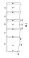
- FIG. 3is a schematic of four battery cells and an interconnect member utilized in the battery module of FIG. 1 ;
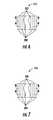
- the system 500includes a clamping device 501 , a component placement machine 502 , a laser 504 , a mirror assembly 506 , an optional electrostatic discharge device 507 , and a computer 508 .
- the laser 504emits a laser beam 509 for a predetermined amount of time.
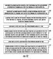
- FIGS. 11 and 15a flowchart of a method for bonding cell terminals of the battery together and for bonding the cell terminals to an interconnect member in accordance with another exemplary embodiment will be explained. It should be understood that the following method can be iteratively performed to bond additional cell terminals of the battery together and to bond the cell terminals to other interconnect members. During the explanation of the following method, it is assumed that the exothermal reactive layer 112 is previously formed on an outer surface of the interconnect member 90 utilizing a vapor deposition method or a magnetron sputtering method for example. Further, it is assumed that the exothermal reactive layer 116 was previously formed on the cell terminal 154 .
Landscapes
- Chemical & Material Sciences (AREA)
- Chemical Kinetics & Catalysis (AREA)
- Electrochemistry (AREA)
- General Chemical & Material Sciences (AREA)
- Engineering & Computer Science (AREA)
- Manufacturing & Machinery (AREA)
- Inorganic Chemistry (AREA)
- Connection Of Batteries Or Terminals (AREA)
- Battery Mounting, Suspending (AREA)
- Secondary Cells (AREA)
Abstract
Description
Claims (9)
Priority Applications (5)
| Application Number | Priority Date | Filing Date | Title |
|---|---|---|---|
| US12/868,111US9005799B2 (en) | 2010-08-25 | 2010-08-25 | Battery module and methods for bonding cell terminals of battery cells together |
| KR1020110079379AKR101271565B1 (en) | 2010-08-25 | 2011-08-10 | Battery Module and Methods for Bonding Cell Terminals of Battery Cells Together |
| EP11820120.1AEP2610946B1 (en) | 2010-08-25 | 2011-08-10 | Battery module, and connection method for a cell terminal of a battery cell |
| PCT/KR2011/005825WO2012026692A2 (en) | 2010-08-25 | 2011-08-10 | Battery module, and connection method for a cell terminal of a battery cell |
| CN201180041095.6ACN103081177B (en) | 2010-08-25 | 2011-08-10 | Battery module and method for joining unit terminals of battery cells together |
Applications Claiming Priority (1)
| Application Number | Priority Date | Filing Date | Title |
|---|---|---|---|
| US12/868,111US9005799B2 (en) | 2010-08-25 | 2010-08-25 | Battery module and methods for bonding cell terminals of battery cells together |
Publications (2)
| Publication Number | Publication Date |
|---|---|
| US20120052364A1 US20120052364A1 (en) | 2012-03-01 |
| US9005799B2true US9005799B2 (en) | 2015-04-14 |
Family
ID=45697677
Family Applications (1)
| Application Number | Title | Priority Date | Filing Date |
|---|---|---|---|
| US12/868,111Active2031-02-06US9005799B2 (en) | 2010-08-25 | 2010-08-25 | Battery module and methods for bonding cell terminals of battery cells together |
Country Status (5)
| Country | Link |
|---|---|
| US (1) | US9005799B2 (en) |
| EP (1) | EP2610946B1 (en) |
| KR (1) | KR101271565B1 (en) |
| CN (1) | CN103081177B (en) |
| WO (1) | WO2012026692A2 (en) |
Families Citing this family (10)
| Publication number | Priority date | Publication date | Assignee | Title |
|---|---|---|---|---|
| US8403019B2 (en) | 2010-05-24 | 2013-03-26 | Lg Chem, Ltd. | Ultrasonic welding assembly and method of attaching an anvil to a bracket of the assembly |
| US20110300438A1 (en)* | 2010-06-07 | 2011-12-08 | Lg Chem, Ltd. | Battery module and methods for bonding a cell terminal of a battery to an interconnect member |
| US9034129B2 (en) | 2011-01-13 | 2015-05-19 | Lg Chem, Ltd. | Ultrasonic welding system and method for forming a weld joint utilizing the ultrasonic welding system |
| US8640760B2 (en) | 2011-08-19 | 2014-02-04 | Lg Chem, Ltd. | Ultrasonic welding machine and method of aligning an ultrasonic welding horn relative to an anvil |
| US8695867B2 (en) | 2011-08-31 | 2014-04-15 | Lg Chem, Ltd. | Ultrasonic welding machine and method of assembling the ultrasonic welding machine |
| KR101509474B1 (en)* | 2012-06-13 | 2015-04-08 | 주식회사 엘지화학 | Battery Assembly Having Single Electrode Terminal Connecting Part |
| US8517078B1 (en) | 2012-07-24 | 2013-08-27 | Lg Chem, Ltd. | Ultrasonic welding assembly and method of attaching an anvil to a bracket of the assembly |
| JP2019133741A (en)* | 2016-05-26 | 2019-08-08 | ヤマハ発動機株式会社 | Power storage module |
| US10431802B2 (en) | 2016-10-14 | 2019-10-01 | Inevit Llc | Battery module including a heat pipe positioned in proximity to a terminal component at a positive or negative terminal of the battery module |
| US20180281093A1 (en)* | 2017-03-31 | 2018-10-04 | GM Global Technology Operations LLC | Solder adhesive for joining of battery tabs |
Citations (189)
| Publication number | Priority date | Publication date | Assignee | Title |
|---|---|---|---|---|
| US2273244A (en) | 1940-04-03 | 1942-02-17 | Electric Storage Battery Co | Storage battery cell |
| US3140859A (en) | 1961-01-17 | 1964-07-14 | Internat Ultrasonics Inc | Electroacoustic sandwich transducers |
| US3164711A (en)* | 1962-08-13 | 1965-01-05 | Gen Motors Corp | Welding method |
| US3179538A (en)* | 1960-12-23 | 1965-04-20 | Yardney International Corp | Terminal connection for electric batteries |
| US3503558A (en) | 1968-03-14 | 1970-03-31 | Electrolux Corp | Exhaust diffusion manifold for a vacuum cleaner or the like |
| US3522100A (en) | 1966-12-19 | 1970-07-28 | Asea Ab | Fuel cell battery |
| US3640775A (en)* | 1970-04-13 | 1972-02-08 | Marathon Mfg Co | Cell terminal |
| US4098966A (en)* | 1977-11-14 | 1978-07-04 | General Motors Corporation | Welded battery elements and process |
| US4292381A (en)* | 1980-01-30 | 1981-09-29 | Energy Research Corporation | Battery construction for uniform electrode current density |
| US4294392A (en) | 1979-01-16 | 1981-10-13 | Lucas Industries Limited | Method of joining a pair of metal parts |
| US4390841A (en) | 1980-10-14 | 1983-06-28 | Purdue Research Foundation | Monitoring apparatus and method for battery power supply |
| US4396689A (en) | 1981-06-01 | 1983-08-02 | Exxon Research And Engineering Co. | Separator-spacer for electrochemical systems |
| US4409304A (en)* | 1981-02-27 | 1983-10-11 | Compagnie Generale Des Etablissements Michelin | Electrochemical device comprising at least two cells connected in electrical series |
| US4423123A (en)* | 1980-04-17 | 1983-12-27 | Shin-Kobe Electric Machinery Co., Ltd. | Electric storage battery and a method of making the same |
| US4767492A (en) | 1986-04-18 | 1988-08-30 | Pola Chemical Industries, Inc. | Ultrasonic fuse-bonding sealing apparatus with improved contact surfaces |
| US5071652A (en) | 1990-12-11 | 1991-12-10 | Globe-Union Inc. | Metal oxide hydrogen battery having improved heat transfer properties |
| US5158842A (en)* | 1992-03-27 | 1992-10-27 | Acme Electric Corporation | Battery terminal connector |
| US5270131A (en) | 1990-12-11 | 1993-12-14 | Sulzer Brothers Limited | Module for a fuel cell battery |
| US5346786A (en) | 1994-03-21 | 1994-09-13 | Hodgetts Philip J | Modular rack mounted battery system |
| US5354630A (en) | 1992-12-10 | 1994-10-11 | Comsat | Ni-H2 battery having improved thermal properties |
| US5357423A (en) | 1993-02-22 | 1994-10-18 | Kulicke And Soffa Investments, Inc. | Apparatus and method for automatically adjusting power output of an ultrasonic generator |
| US5364711A (en) | 1992-04-01 | 1994-11-15 | Kabushiki Kaisha Toshiba | Fuel cell |
| US5371337A (en)* | 1992-10-09 | 1994-12-06 | General Motors Corporation | Welding process and apparatus |
| US5385793A (en) | 1992-07-20 | 1995-01-31 | Globe-Union Inc. | Thermal management of battery systems |
| US5487958A (en) | 1993-12-06 | 1996-01-30 | Tura; Drew | Interlocking frame system for lithium-polymer battery construction |
| US5487955A (en) | 1994-03-15 | 1996-01-30 | Electric Fuel (E.F.L.) Ltd. | Cooled zinc-oxygen battery |
| US5510203A (en) | 1994-02-23 | 1996-04-23 | Matsushita Electric Industrial Co., Ltd. | Cell and module battery of sealed alkaline storage battery |
| US5520976A (en) | 1993-06-30 | 1996-05-28 | Simmonds Precision Products Inc. | Composite enclosure for electronic hardware |
| US5561005A (en) | 1993-04-28 | 1996-10-01 | Sony Corporation | Secondary battery having non-aqueous electrolyte |
| US5589290A (en) | 1994-03-04 | 1996-12-31 | Deutsche Automobilgesellschaft Mbh | Battery box with fluid flow channels to maintain proper temperature |
| US5603444A (en) | 1995-08-22 | 1997-02-18 | Ultex Corporation | Ultrasonic bonding machine and resonator thereof |
| US5606242A (en) | 1994-10-04 | 1997-02-25 | Duracell, Inc. | Smart battery algorithm for reporting battery parameters to an external device |
| US5652502A (en) | 1994-11-10 | 1997-07-29 | Duracell, Inc. | Battery pack having a processor controlled battery operating system |
| US5658682A (en) | 1992-12-11 | 1997-08-19 | Honda Giken Kogyo Kabushiki Kaisha | Process for detecting remaining capacity of battery |
| JPH09219213A (en) | 1996-02-09 | 1997-08-19 | Nissan Motor Co Ltd | Secondary battery for electric vehicle and its temperature rise alleviation device |
| US5663007A (en) | 1994-02-23 | 1997-09-02 | Matsushita Electric Industrial Co., Ltd. | Sealed storage battery and method for manufacturing the same |
| US5693432A (en) | 1994-12-29 | 1997-12-02 | Ishihara Sangyo Kaisha, Ltd. | Porous material-polymeric solid electrolyte composite, method for producing same and photoelectric conversion device using same |
| US5756227A (en) | 1994-11-18 | 1998-05-26 | Honda Giken Kogyo Kabushiki Kaisha | Battery assembly with temperature control mechanism |
| JPH10199510A (en) | 1997-01-10 | 1998-07-31 | Sanyo Electric Co Ltd | Negative electrode for lithium battery and lithium battery |
| US5825155A (en) | 1993-08-09 | 1998-10-20 | Kabushiki Kaisha Toshiba | Battery set structure and charge/ discharge control apparatus for lithium-ion battery |
| US5871861A (en)* | 1994-04-05 | 1999-02-16 | Mitsubishi Chemical Corporation | Lithium ion secondary cell |
| US5873826A (en) | 1996-07-19 | 1999-02-23 | Ge Yokogawa Medical Systems, Limited | Fluoroscopy method and X-ray CT apparatus |
| JPH1166949A (en) | 1997-08-18 | 1999-03-09 | Kureha Chem Ind Co Ltd | Gel solid electrolyte forming high polymer matrix, solid electrolyte and battery |
| EP0736226B1 (en) | 1993-12-22 | 1999-03-24 | Ballard Power Systems Inc. | Electrochemical fuel cell employing ambient air as the oxidant and coolant |
| US5919539A (en) | 1996-02-12 | 1999-07-06 | E. I. Du Pont De Nemours And Company | Ultrasonic seaming of spunbonded polyolefin sheet material |
| JPH11191432A (en) | 1997-12-26 | 1999-07-13 | Fuji Elelctrochem Co Ltd | Lithium secondary battery |
| US5982403A (en) | 1992-11-30 | 1999-11-09 | Ricoh Company, Ltd. | Potential estimating apparatus using a plurality of neural networks for carrying out an electrographic process |
| US6016047A (en) | 1996-11-21 | 2000-01-18 | U.S. Philips Corporation | Battery management system and battery simulator |
| US6027831A (en)* | 1996-12-26 | 2000-02-22 | Matsushita Electric Industrial Co., Ltd. | Square type enclosed storage battery |
| US6099986A (en) | 1997-07-25 | 2000-08-08 | 3M Innovative Properties Company | In-situ short circuit protection system and method for high-energy electrochemical cells |
| US6117584A (en) | 1997-07-25 | 2000-09-12 | 3M Innovative Properties Company | Thermal conductor for high-energy electrochemical cells |
| US6121752A (en) | 1997-11-21 | 2000-09-19 | Hitachi, Ltd. | Battery unit having a plurality of rechargeable battery cells and method of charging the same |
| US6150753A (en) | 1997-12-15 | 2000-11-21 | Cae Blackstone | Ultrasonic transducer assembly having a cobalt-base alloy housing |
| US6257328B1 (en) | 1997-10-14 | 2001-07-10 | Matsushita Electric Industrial Co., Ltd. | Thermal conductive unit and thermal connection structure using the same |
| US20010046624A1 (en) | 2000-05-19 | 2001-11-29 | Shin-Kobe Electric Machinery Co.,Ltd. | Battery structure for electric vehicle and battery module |
| US6353815B1 (en) | 1998-11-04 | 2002-03-05 | The United States Of America As Represented By The United States Department Of Energy | Statistically qualified neuro-analytic failure detection method and system |
| US20020031603A1 (en) | 2000-07-14 | 2002-03-14 | Jsr Corporation | Coating method by intermetallic compound |
| US6362598B2 (en) | 2000-04-29 | 2002-03-26 | Vb Autobatterie Gmbh | Method for determining the state of charge and loading capacity of an electrical storage battery |
| US6406812B1 (en) | 1999-04-23 | 2002-06-18 | Oldham France S.A. | Continuous current supply for electrical automotive vehicle |
| US6413678B1 (en) | 1999-03-03 | 2002-07-02 | Ube Industries, Inc. | Non-aqueous electrolyte and lithium secondary battery using the same |
| US6422027B1 (en) | 2001-05-03 | 2002-07-23 | Ford Global Tech., Inc. | System and method for cooling a battery pack |
| US6441586B1 (en) | 2001-03-23 | 2002-08-27 | General Motors Corporation | State of charge prediction method and apparatus for a battery |
| US6448741B1 (en) | 1998-09-03 | 2002-09-10 | Matsushita Electric Industrial Co., Ltd. | Temperature control method and structure for a battery pack |
| US6462949B1 (en) | 2000-08-07 | 2002-10-08 | Thermotek, Inc. | Electronic enclosure cooling system |
| US6475659B1 (en) | 1998-11-17 | 2002-11-05 | C&D Charter Holdings Inc. | Selectable capacity fixed footprint lead-acid battery racking system with horizontal plates |
| US6515454B2 (en) | 2001-02-13 | 2003-02-04 | Robert Bosch Gmbh | Method and system for determining the capacity of a battery |
| US6534954B1 (en) | 2002-01-10 | 2003-03-18 | Compact Power Inc. | Method and apparatus for a battery state of charge estimator |
| US20030082440A1 (en) | 2001-10-29 | 2003-05-01 | Johnson Controls Technology Company | Battery system |
| US6563318B2 (en) | 2000-05-23 | 2003-05-13 | Canon Kabushiki Kaisha | Detecting method for detecting internal state of a rechargeable battery, detecting device for practicing said detecting method, and instrument provided with said detecting device |
| JP2003165161A (en) | 2001-12-03 | 2003-06-10 | Mishima Daiji | Ultrasonic vibratory welding device and ultrasonic vibratory horn |
| JP2003219572A (en) | 2002-01-17 | 2003-07-31 | Matsushita Electric Ind Co Ltd | Battery assembly system |
| WO2003071616A2 (en) | 2002-02-19 | 2003-08-28 | 3M Innovative Properties Company | Temperature control apparatus and method for high energy electrochemical cells |
| US20030184307A1 (en) | 2002-02-19 | 2003-10-02 | Kozlowski James D. | Model-based predictive diagnostic tool for primary and secondary batteries |
| US20040021442A1 (en) | 2002-07-30 | 2004-02-05 | Nissan Motor Co., Ltd. | Battery module |
| US20040023108A1 (en) | 2002-08-05 | 2004-02-05 | Naoya Nakanishi | Battery |
| US6709783B2 (en) | 2000-01-12 | 2004-03-23 | Matsushita Electric Industrial Co., Ltd. | Battery pack cooling structure |
| US6724172B2 (en) | 2002-06-26 | 2004-04-20 | Hyundai Motor Company | Method for determining a maximum charge current and a maximum discharge current of a battery |
| US6736942B2 (en)* | 2000-05-02 | 2004-05-18 | Johns Hopkins University | Freestanding reactive multilayer foils |
| EP1435675A1 (en) | 2001-09-03 | 2004-07-07 | Andrey Veniaminovich Popov | Accumulator |
| CN1512518A (en) | 2002-12-27 | 2004-07-14 | 中国科学院物理研究所 | A kind of composite electrolyte and its application |
| US6771502B2 (en) | 2002-06-28 | 2004-08-03 | Advanced Energy Technology Inc. | Heat sink made from longer and shorter graphite sheets |
| US6780538B2 (en) | 1999-07-22 | 2004-08-24 | Matsushita Electric Industrial Co., Ltd. | Battery module, and rechargeable battery for constituting the battery module |
| US6821367B1 (en) | 2003-03-31 | 2004-11-23 | Steelcase Development Corporation | Ultrasonic tool and method for securing a covering to a frame |
| US6821671B2 (en) | 2002-03-01 | 2004-11-23 | Lg Chem, Ltd. | Method and apparatus for cooling and positioning prismatic battery cells |
| US6829562B2 (en) | 2001-02-13 | 2004-12-07 | Robert Bosch Gmbh | Method and device for state sensing of technical systems such as energy stores |
| US6832171B2 (en) | 2002-12-29 | 2004-12-14 | Texas Instruments Incorporated | Circuit and method for determining battery impedance increase with aging |
| JP2005503265A (en) | 2001-09-21 | 2005-02-03 | スリーエム イノベイティブ プロパティズ カンパニー | Rotating ultrasonic horn mounting device and mounting method |
| US20050026014A1 (en) | 2003-07-31 | 2005-02-03 | Michael Fogaing | Polymer batteries having thermal exchange apparatus |
| US6876175B2 (en) | 2001-06-29 | 2005-04-05 | Robert Bosch Gmbh | Methods for determining the charge state and/or the power capacity of charge store |
| US6886249B2 (en) | 2001-05-02 | 2005-05-03 | Advanced Energy Technology Inc. | Method for making finned heat sink assemblies |
| US6892148B2 (en) | 2002-12-29 | 2005-05-10 | Texas Instruments Incorporated | Circuit and method for measurement of battery capacity fade |
| US20050100786A1 (en) | 2003-09-19 | 2005-05-12 | Ryu Duk H. | Nonaqueous lithium secondary battery with cyclability and/or high temperature safety improved |
| JP2005126315A (en) | 2003-09-30 | 2005-05-19 | Hitachi Ltd | Hydrogen storage and supply device, its system, and distributed power and car using the same |
| US20050127874A1 (en) | 2003-12-12 | 2005-06-16 | Myoungho Lim | Method and apparatus for multiple battery cell management |
| US20050134038A1 (en) | 2003-12-17 | 2005-06-23 | Eaton Corporation | Fitting for fluid conveyance |
| US6927554B2 (en) | 2003-08-28 | 2005-08-09 | General Motors Corporation | Simple optimal estimator for PbA state of charge |
| US6943528B2 (en) | 2000-11-17 | 2005-09-13 | Robert Bosch Gmbh | Method and arrangement for determination of the state of charge of a battery |
| US20050202311A1 (en) | 2004-03-11 | 2005-09-15 | Nissan Motor Co., Ltd. | Battery |
| US6967466B2 (en) | 2002-08-31 | 2005-11-22 | Vb Autobatterie Gmbh | Method for determining the amount of charge which can be drawn on a storage battery, and monitoring device for a storage battery |
| KR20050121116A (en) | 2004-06-21 | 2005-12-26 | 삼성에스디아이 주식회사 | Secondary battery |
| US6982131B1 (en) | 1999-10-08 | 2006-01-03 | Matsushita Electric Industrial Co., Ltd. | Structure for electrode terminals of battery module |
| US7012434B2 (en) | 2002-07-13 | 2006-03-14 | Vb Autobatterie Gmbh | Method for determining the amount of charge which can be drawn from a storage battery and monitoring device |
| US7026073B2 (en) | 2001-01-29 | 2006-04-11 | Matsushita Electric Industrial Co., Ltd. | Non-aqueous electrolyte secondary battery |
| US7039534B1 (en) | 2003-11-03 | 2006-05-02 | Ryno Ronald A | Charging monitoring systems |
| US20060100833A1 (en) | 2004-11-11 | 2006-05-11 | Plett Gregory L | State and parameter estimation for an electrochemical cell |
| US7061246B2 (en) | 2001-12-06 | 2006-06-13 | Johnson Controls Technology Company | Battery monitoring system and method |
| US7072871B1 (en) | 2001-08-22 | 2006-07-04 | Cadex Electronics Inc. | Fuzzy logic method and apparatus for battery state of health determination |
| US20060174994A1 (en) | 2004-11-18 | 2006-08-10 | Dawn White | Closed-loop control of power used in ultrasonic consolidation |
| JP2006212692A (en) | 2005-02-07 | 2006-08-17 | Denso Corp | Ultrasonic joining method and device therefor |
| US7098665B2 (en) | 2002-11-13 | 2006-08-29 | Vb Autobatterie Gmbh | Method for prediction of the internal resistance of an energy storage battery, and a monitoring device for energy storage batteries |
| WO2006090511A1 (en) | 2005-02-22 | 2006-08-31 | Nec Corporation | Manufacturing method of electrical device assembly |
| US7109685B2 (en) | 2003-09-17 | 2006-09-19 | General Motors Corporation | Method for estimating states and parameters of an electrochemical cell |
| US20060225842A1 (en) | 2005-03-31 | 2006-10-12 | Xerox Corporation | Treatment for ultrasonic welding |
| US7126312B2 (en) | 2004-07-28 | 2006-10-24 | Enerdel, Inc. | Method and apparatus for balancing multi-cell lithium battery systems |
| US7147045B2 (en) | 1998-06-08 | 2006-12-12 | Thermotek, Inc. | Toroidal low-profile extrusion cooling system and method thereof |
| US20070037051A1 (en) | 2005-08-10 | 2007-02-15 | Kim Tae-Yong | Battery module with improved cell barrier between unit cells |
| US7197487B2 (en) | 2005-03-16 | 2007-03-27 | Lg Chem, Ltd. | Apparatus and method for estimating battery state of charge |
| US7199557B2 (en) | 2003-07-01 | 2007-04-03 | Eaton Power Quality Company | Apparatus, methods and computer program products for estimation of battery reserve life using adaptively modified state of health indicator-based reserve life models |
| US20070087266A1 (en) | 2005-10-18 | 2007-04-19 | Debbi Bourke | Modular battery system |
| US20070120533A1 (en) | 2005-11-30 | 2007-05-31 | Plett Gregory L | System, method, and article of manufacture for determining an estimated battery parameter vector |
| US20070126396A1 (en) | 2005-12-02 | 2007-06-07 | Lg Chem, Ltd. | Battery module of high cooling efficiency |
| US7229327B2 (en) | 2005-05-25 | 2007-06-12 | Alcoa Fujikura Limited | Canted coil spring power terminal and sequence connection system |
| KR20070060161A (en) | 2000-05-02 | 2007-06-12 | 존스 홉킨스 유니버시티 | Bonding method and articles made by this bonding method |
| US7250741B2 (en) | 2003-08-13 | 2007-07-31 | Hyundai Motor Company | Method and system for calculating available power of a battery |
| US7251889B2 (en) | 2000-06-30 | 2007-08-07 | Swales & Associates, Inc. | Manufacture of a heat transfer system |
| US7253587B2 (en) | 2003-08-06 | 2007-08-07 | Vb Autobatterie Gmbh | Method for prediction of electrical characteristics of an electrochemical storage battery |
| US7264902B2 (en) | 2001-07-04 | 2007-09-04 | Nissan Motor Co., Ltd. | Battery system with excellent controllability for temperature |
| KR100765659B1 (en) | 2005-08-09 | 2007-10-10 | 현대자동차주식회사 | Fuel cell stack structure for automobile |
| KR20070104904A (en) | 2005-01-03 | 2007-10-29 | 쓰리엠 이노베이티브 프로퍼티즈 컴파니 | Method and apparatus for controlling the gap between horn and anvil in ultrasonic welding system |
| US20070257087A1 (en) | 2006-05-08 | 2007-11-08 | Dukane Corporation | Ultrasonic press using servo motor with integrated linear actuator |
| KR20070109929A (en) | 2006-05-11 | 2007-11-15 | 인다크 게젤샤프트 퓌어 인두스트리에베다르프 엠베하 운트 코. 베트리브즈 카게 | Anvil for ultrasonic welding and device for ultrasonic welding |
| US7315789B2 (en) | 2004-11-23 | 2008-01-01 | Lg Chem, Ltd. | Method and system for battery parameter estimation |
| US7321220B2 (en) | 2003-11-20 | 2008-01-22 | Lg Chem, Ltd. | Method for calculating power capability of battery packs using advanced cell model predictive techniques |
| US7327147B2 (en) | 2004-02-04 | 2008-02-05 | Vb Autobatterie Gmbh & Co. Kgaa | Device and method for determining characteristic variables for batteries |
| JP2008080995A (en) | 2006-09-28 | 2008-04-10 | Denso Corp | Cooling system |
| KR20080047641A (en) | 2006-11-27 | 2008-05-30 | 주식회사 엘지화학 | Power system with thermal radiation protection |
| US20080131700A1 (en) | 2005-03-30 | 2008-06-05 | Reactive Nanotechnologies, Inc | Method For Fabricating Large Dimension Bonds Using Reactive Multilayer Joining |
| US7400115B2 (en) | 2006-02-09 | 2008-07-15 | Lg Chem, Ltd. | System, method, and article of manufacture for determining an estimated combined battery state-parameter vector |
| JP2008183622A (en) | 2008-02-22 | 2008-08-14 | Yazaki Corp | Ultrasonic welding equipment |
| KR20080077424A (en) | 2007-02-20 | 2008-08-25 | 삼성에스디아이 주식회사 | Secondary Battery and Manufacturing Method Thereof |
| US7446504B2 (en) | 2005-11-10 | 2008-11-04 | Lg Chem, Ltd. | System, method, and article of manufacture for determining an estimated battery state vector |
| US7479758B2 (en) | 2004-12-10 | 2009-01-20 | Lg Chem, Ltd. | Battery pack casing with lock type connector |
| US20090029239A1 (en) | 2007-07-26 | 2009-01-29 | Lg Chem, Ltd | Battery cell carrier assembly having a battery cell carrier for holding a battery cell therein |
| KR100889241B1 (en) | 2006-10-23 | 2009-03-17 | 주식회사 엘지화학 | Electrode terminal connection member of battery module |
| US7518339B2 (en) | 2003-01-30 | 2009-04-14 | Robert Bosch Gmbh | State variable and parameter estimator comprising several partial models for an electrical energy storage device |
| US20090098416A1 (en) | 2007-04-12 | 2009-04-16 | Sony Corporation | Battery pack |
| US7521895B2 (en) | 2006-03-02 | 2009-04-21 | Lg Chem, Ltd. | System and method for determining both an estimated battery state vector and an estimated battery parameter vector |
| US7525285B2 (en) | 2004-11-11 | 2009-04-28 | Lg Chem, Ltd. | Method and system for cell equalization using state of charge |
| US20090111015A1 (en)* | 2006-05-11 | 2009-04-30 | Johnson Controls - Saft Advanced Power Solutions Llc | Modular battery system |
| JP2009090364A (en) | 2007-10-12 | 2009-04-30 | Sanko Kikai Kk | Ultrasonic sealing device |
| US20090186265A1 (en) | 2008-01-18 | 2009-07-23 | Lg Chem, Ltd | Battery cell assembly and method for assembling the battery cell assembly |
| US7583059B2 (en) | 2003-12-18 | 2009-09-01 | Lg Chem, Ltd. | Apparatus and method for estimating state of charge of battery using neural network |
| US7589532B2 (en) | 2005-08-23 | 2009-09-15 | Lg Chem, Ltd. | System and method for estimating a state vector associated with a battery |
| US7600664B2 (en) | 2003-07-04 | 2009-10-13 | Schunk Ultraschalltechnik Gmbh | Welding device and method for welding workpieces |
| KR100921346B1 (en) | 2006-09-25 | 2009-10-13 | 주식회사 엘지화학 | Medium and large battery module and battery module assembly |
| US20090255979A1 (en) | 2008-04-11 | 2009-10-15 | Tdk Corporation | Ultrasonic mounting apparatus |
| US20090297942A1 (en)* | 2008-06-03 | 2009-12-03 | Samsung Sdi Co., Ltd. | Lithium polymer battery |
| US20090297892A1 (en)* | 2008-04-14 | 2009-12-03 | A123 Systems, Inc. | Flexible Voltage Nested Battery Module Design |
| US20090311607A1 (en) | 2007-12-25 | 2009-12-17 | Byd Co., Ltd. | Battery electrode sheet |
| US20090325054A1 (en) | 2008-06-30 | 2009-12-31 | Lg Chem, Ltd. | Battery Cell Assembly Having Heat Exchanger With Serpentine Flow Path |
| US20090325051A1 (en) | 2008-06-30 | 2009-12-31 | Lg Chem, Ltd. | Battery Module Having a Rubber Cooling Manifold |
| US20090325055A1 (en) | 2008-06-30 | 2009-12-31 | Lg Chem, Ltd. | Battery module having cooling manifold with ported screws and method for cooling the battery module |
| US20090325053A1 (en) | 2008-06-30 | 2009-12-31 | Lg Chem, Ltd. | Battery Module Having Battery Cell Assembly with Heat Exchanger |
| US20090325059A1 (en) | 2008-06-30 | 2009-12-31 | Lg Chem, Ltd. | Battery Module Having Battery Cell Assemblies With Alignment-Coupling Features |
| US20090325052A1 (en) | 2008-06-30 | 2009-12-31 | Lg Chem, Ltd. | Battery Module Having Cooling Manifold and Method for Cooling Battery Module |
| US20100038409A1 (en)* | 2007-04-30 | 2010-02-18 | Airbus Deutschland Gmbh | Joining Method For Joining Components |
| US20100086842A1 (en) | 2008-10-06 | 2010-04-08 | Lg Chem, Ltd. | Battery cell assembly and method for assembling the battery cell assembly |
| US20100190055A1 (en) | 2009-01-29 | 2010-07-29 | Gm Global Technology Operations, Inc. | Battery cell connection method and apparatus |
| US20100276086A1 (en) | 2005-01-03 | 2010-11-04 | 3M Innovative Properties Company | Method and system for determining a gap between a vibrational body and fixed point |
| US20100281681A1 (en) | 2009-05-06 | 2010-11-11 | Gm Global Technology Operations, Inc. | Method for Manufacture of Battery Pouch Terminals |
| US20110108181A1 (en) | 2009-11-09 | 2011-05-12 | Gm Global Technology Operations, Inc. | Method and system for online quality monitoring and control of a vibration welding process |
| US20110114705A1 (en)* | 2009-11-19 | 2011-05-19 | Santa Barbara Infrared | Method for creating thermal bonds while minimizing heating of parts |
| US20110117420A1 (en)* | 2009-11-19 | 2011-05-19 | Sung-Bae Kim | Bus bar and battery module including the same |
| US20110229745A1 (en)* | 2010-03-19 | 2011-09-22 | Gm Global Technology Operations, Inc. | Interconnect device for battery assembly |
| US20110284169A1 (en) | 2010-05-24 | 2011-11-24 | Lg Chem, Ltd. | Ultrasonic welding assembly and method of attaching an anvil to a bracket of the assembly |
| US20110287300A1 (en)* | 2010-05-20 | 2011-11-24 | Sang-Won Byun | Rechargeable battery and battery module |
| US20110293992A1 (en)* | 2010-05-27 | 2011-12-01 | Gm Global Technology Operations, Inc. | Battery connection topology |
| US20110300438A1 (en) | 2010-06-07 | 2011-12-08 | Lg Chem, Ltd. | Battery module and methods for bonding a cell terminal of a battery to an interconnect member |
| US20110308736A1 (en) | 2010-06-18 | 2011-12-22 | Gm Global Technology Operations, Inc. | Alignment Tool For Replacement Of Ultrasonic Welder Horn |
| US8088516B2 (en)* | 2005-11-18 | 2012-01-03 | Acme Aerospace, Inc. | Storage battery electrodes with integral conductors |
| US20120111924A1 (en)* | 2005-08-05 | 2012-05-10 | Fuji Electric Systems Co., Ltd. | Lead-free solder |
| US8177878B2 (en)* | 2009-11-30 | 2012-05-15 | Infineon Technologies Ag | Bonding material with exothermically reactive heterostructures |
| US20120158168A1 (en) | 2010-12-16 | 2012-06-21 | Lg Chem, Ltd. | System and method for determining whether an ultrasonic horn is aligned with an anvil |
| US20120153006A1 (en) | 2010-12-16 | 2012-06-21 | Lg Chem, Ltd. | Ultrasonic welding system and method for forming a weld joint |
| US20120180929A1 (en) | 2011-01-13 | 2012-07-19 | Lg Chem, Ltd. | Ultrasonic welding system and method for forming a weld joint utilizing the ultrasonic welding system |
| US20130042959A1 (en) | 2011-08-19 | 2013-02-21 | Lg Chem, Ltd. | Ultrasonic welding machine and method of aligning an ultrasonic welding horn relative to an anvil |
| US20130048698A1 (en) | 2011-08-31 | 2013-02-28 | Lg Chem, Ltd. | Ultrasonic welding machine and method of assembling the ultrasonic welding machine |
| US8517078B1 (en) | 2012-07-24 | 2013-08-27 | Lg Chem, Ltd. | Ultrasonic welding assembly and method of attaching an anvil to a bracket of the assembly |
| US8563159B2 (en)* | 2010-08-04 | 2013-10-22 | Bren-Tronics Batteries International, L.L.C. | Structure and method for removing battery cell heat |
- 2010
- 2010-08-25USUS12/868,111patent/US9005799B2/enactiveActive
- 2011
- 2011-08-10WOPCT/KR2011/005825patent/WO2012026692A2/enactiveApplication Filing
- 2011-08-10KRKR1020110079379Apatent/KR101271565B1/enactiveActive
- 2011-08-10CNCN201180041095.6Apatent/CN103081177B/enactiveActive
- 2011-08-10EPEP11820120.1Apatent/EP2610946B1/enactiveActive
Patent Citations (196)
| Publication number | Priority date | Publication date | Assignee | Title |
|---|---|---|---|---|
| US2273244A (en) | 1940-04-03 | 1942-02-17 | Electric Storage Battery Co | Storage battery cell |
| US3179538A (en)* | 1960-12-23 | 1965-04-20 | Yardney International Corp | Terminal connection for electric batteries |
| US3140859A (en) | 1961-01-17 | 1964-07-14 | Internat Ultrasonics Inc | Electroacoustic sandwich transducers |
| US3164711A (en)* | 1962-08-13 | 1965-01-05 | Gen Motors Corp | Welding method |
| US3522100A (en) | 1966-12-19 | 1970-07-28 | Asea Ab | Fuel cell battery |
| US3503558A (en) | 1968-03-14 | 1970-03-31 | Electrolux Corp | Exhaust diffusion manifold for a vacuum cleaner or the like |
| US3640775A (en)* | 1970-04-13 | 1972-02-08 | Marathon Mfg Co | Cell terminal |
| US4098966A (en)* | 1977-11-14 | 1978-07-04 | General Motors Corporation | Welded battery elements and process |
| US4294392A (en) | 1979-01-16 | 1981-10-13 | Lucas Industries Limited | Method of joining a pair of metal parts |
| US4292381A (en)* | 1980-01-30 | 1981-09-29 | Energy Research Corporation | Battery construction for uniform electrode current density |
| US4423123A (en)* | 1980-04-17 | 1983-12-27 | Shin-Kobe Electric Machinery Co., Ltd. | Electric storage battery and a method of making the same |
| US4390841A (en) | 1980-10-14 | 1983-06-28 | Purdue Research Foundation | Monitoring apparatus and method for battery power supply |
| US4409304A (en)* | 1981-02-27 | 1983-10-11 | Compagnie Generale Des Etablissements Michelin | Electrochemical device comprising at least two cells connected in electrical series |
| US4396689A (en) | 1981-06-01 | 1983-08-02 | Exxon Research And Engineering Co. | Separator-spacer for electrochemical systems |
| US4767492A (en) | 1986-04-18 | 1988-08-30 | Pola Chemical Industries, Inc. | Ultrasonic fuse-bonding sealing apparatus with improved contact surfaces |
| US5270131A (en) | 1990-12-11 | 1993-12-14 | Sulzer Brothers Limited | Module for a fuel cell battery |
| US5071652A (en) | 1990-12-11 | 1991-12-10 | Globe-Union Inc. | Metal oxide hydrogen battery having improved heat transfer properties |
| US5158842A (en)* | 1992-03-27 | 1992-10-27 | Acme Electric Corporation | Battery terminal connector |
| US5364711A (en) | 1992-04-01 | 1994-11-15 | Kabushiki Kaisha Toshiba | Fuel cell |
| US5385793A (en) | 1992-07-20 | 1995-01-31 | Globe-Union Inc. | Thermal management of battery systems |
| US5371337A (en)* | 1992-10-09 | 1994-12-06 | General Motors Corporation | Welding process and apparatus |
| US5982403A (en) | 1992-11-30 | 1999-11-09 | Ricoh Company, Ltd. | Potential estimating apparatus using a plurality of neural networks for carrying out an electrographic process |
| US5354630A (en) | 1992-12-10 | 1994-10-11 | Comsat | Ni-H2 battery having improved thermal properties |
| EP0673553B1 (en) | 1992-12-10 | 2001-02-21 | Comsat Corporation | Ni-h2 battery having improved thermal properties |
| US5658682A (en) | 1992-12-11 | 1997-08-19 | Honda Giken Kogyo Kabushiki Kaisha | Process for detecting remaining capacity of battery |
| US5357423A (en) | 1993-02-22 | 1994-10-18 | Kulicke And Soffa Investments, Inc. | Apparatus and method for automatically adjusting power output of an ultrasonic generator |
| US5561005A (en) | 1993-04-28 | 1996-10-01 | Sony Corporation | Secondary battery having non-aqueous electrolyte |
| US5520976A (en) | 1993-06-30 | 1996-05-28 | Simmonds Precision Products Inc. | Composite enclosure for electronic hardware |
| US5825155A (en) | 1993-08-09 | 1998-10-20 | Kabushiki Kaisha Toshiba | Battery set structure and charge/ discharge control apparatus for lithium-ion battery |
| US5487958A (en) | 1993-12-06 | 1996-01-30 | Tura; Drew | Interlocking frame system for lithium-polymer battery construction |
| EP0736226B1 (en) | 1993-12-22 | 1999-03-24 | Ballard Power Systems Inc. | Electrochemical fuel cell employing ambient air as the oxidant and coolant |
| US5510203A (en) | 1994-02-23 | 1996-04-23 | Matsushita Electric Industrial Co., Ltd. | Cell and module battery of sealed alkaline storage battery |
| US5663007A (en) | 1994-02-23 | 1997-09-02 | Matsushita Electric Industrial Co., Ltd. | Sealed storage battery and method for manufacturing the same |
| US5589290A (en) | 1994-03-04 | 1996-12-31 | Deutsche Automobilgesellschaft Mbh | Battery box with fluid flow channels to maintain proper temperature |
| US5487955A (en) | 1994-03-15 | 1996-01-30 | Electric Fuel (E.F.L.) Ltd. | Cooled zinc-oxygen battery |
| US5346786A (en) | 1994-03-21 | 1994-09-13 | Hodgetts Philip J | Modular rack mounted battery system |
| US5871861A (en)* | 1994-04-05 | 1999-02-16 | Mitsubishi Chemical Corporation | Lithium ion secondary cell |
| US5606242A (en) | 1994-10-04 | 1997-02-25 | Duracell, Inc. | Smart battery algorithm for reporting battery parameters to an external device |
| US5652502A (en) | 1994-11-10 | 1997-07-29 | Duracell, Inc. | Battery pack having a processor controlled battery operating system |
| US5796239A (en) | 1994-11-10 | 1998-08-18 | Van Phuoc; Duong | Battery pack having a processor controlled battery operating system |
| US5756227A (en) | 1994-11-18 | 1998-05-26 | Honda Giken Kogyo Kabushiki Kaisha | Battery assembly with temperature control mechanism |
| US5693432A (en) | 1994-12-29 | 1997-12-02 | Ishihara Sangyo Kaisha, Ltd. | Porous material-polymeric solid electrolyte composite, method for producing same and photoelectric conversion device using same |
| US5603444A (en) | 1995-08-22 | 1997-02-18 | Ultex Corporation | Ultrasonic bonding machine and resonator thereof |
| JPH09219213A (en) | 1996-02-09 | 1997-08-19 | Nissan Motor Co Ltd | Secondary battery for electric vehicle and its temperature rise alleviation device |
| US5919539A (en) | 1996-02-12 | 1999-07-06 | E. I. Du Pont De Nemours And Company | Ultrasonic seaming of spunbonded polyolefin sheet material |
| US5873826A (en) | 1996-07-19 | 1999-02-23 | Ge Yokogawa Medical Systems, Limited | Fluoroscopy method and X-ray CT apparatus |
| US6016047A (en) | 1996-11-21 | 2000-01-18 | U.S. Philips Corporation | Battery management system and battery simulator |
| US6027831A (en)* | 1996-12-26 | 2000-02-22 | Matsushita Electric Industrial Co., Ltd. | Square type enclosed storage battery |
| JPH10199510A (en) | 1997-01-10 | 1998-07-31 | Sanyo Electric Co Ltd | Negative electrode for lithium battery and lithium battery |
| US6099986A (en) | 1997-07-25 | 2000-08-08 | 3M Innovative Properties Company | In-situ short circuit protection system and method for high-energy electrochemical cells |
| US6117584A (en) | 1997-07-25 | 2000-09-12 | 3M Innovative Properties Company | Thermal conductor for high-energy electrochemical cells |
| JPH1166949A (en) | 1997-08-18 | 1999-03-09 | Kureha Chem Ind Co Ltd | Gel solid electrolyte forming high polymer matrix, solid electrolyte and battery |
| US6257328B1 (en) | 1997-10-14 | 2001-07-10 | Matsushita Electric Industrial Co., Ltd. | Thermal conductive unit and thermal connection structure using the same |
| US6121752A (en) | 1997-11-21 | 2000-09-19 | Hitachi, Ltd. | Battery unit having a plurality of rechargeable battery cells and method of charging the same |
| US6150753A (en) | 1997-12-15 | 2000-11-21 | Cae Blackstone | Ultrasonic transducer assembly having a cobalt-base alloy housing |
| JPH11191432A (en) | 1997-12-26 | 1999-07-13 | Fuji Elelctrochem Co Ltd | Lithium secondary battery |
| US7147045B2 (en) | 1998-06-08 | 2006-12-12 | Thermotek, Inc. | Toroidal low-profile extrusion cooling system and method thereof |
| US6448741B1 (en) | 1998-09-03 | 2002-09-10 | Matsushita Electric Industrial Co., Ltd. | Temperature control method and structure for a battery pack |
| US6353815B1 (en) | 1998-11-04 | 2002-03-05 | The United States Of America As Represented By The United States Department Of Energy | Statistically qualified neuro-analytic failure detection method and system |
| US6475659B1 (en) | 1998-11-17 | 2002-11-05 | C&D Charter Holdings Inc. | Selectable capacity fixed footprint lead-acid battery racking system with horizontal plates |
| US6413678B1 (en) | 1999-03-03 | 2002-07-02 | Ube Industries, Inc. | Non-aqueous electrolyte and lithium secondary battery using the same |
| US6406812B1 (en) | 1999-04-23 | 2002-06-18 | Oldham France S.A. | Continuous current supply for electrical automotive vehicle |
| US6780538B2 (en) | 1999-07-22 | 2004-08-24 | Matsushita Electric Industrial Co., Ltd. | Battery module, and rechargeable battery for constituting the battery module |
| US6982131B1 (en) | 1999-10-08 | 2006-01-03 | Matsushita Electric Industrial Co., Ltd. | Structure for electrode terminals of battery module |
| US6709783B2 (en) | 2000-01-12 | 2004-03-23 | Matsushita Electric Industrial Co., Ltd. | Battery pack cooling structure |
| US6362598B2 (en) | 2000-04-29 | 2002-03-26 | Vb Autobatterie Gmbh | Method for determining the state of charge and loading capacity of an electrical storage battery |
| US20040247931A1 (en) | 2000-05-02 | 2004-12-09 | Weihs Timothy P. | Method of bonding bodies |
| US6736942B2 (en)* | 2000-05-02 | 2004-05-18 | Johns Hopkins University | Freestanding reactive multilayer foils |
| KR20070060161A (en) | 2000-05-02 | 2007-06-12 | 존스 홉킨스 유니버시티 | Bonding method and articles made by this bonding method |
| US20010046624A1 (en) | 2000-05-19 | 2001-11-29 | Shin-Kobe Electric Machinery Co.,Ltd. | Battery structure for electric vehicle and battery module |
| US6563318B2 (en) | 2000-05-23 | 2003-05-13 | Canon Kabushiki Kaisha | Detecting method for detecting internal state of a rechargeable battery, detecting device for practicing said detecting method, and instrument provided with said detecting device |
| US7251889B2 (en) | 2000-06-30 | 2007-08-07 | Swales & Associates, Inc. | Manufacture of a heat transfer system |
| US20020031603A1 (en) | 2000-07-14 | 2002-03-14 | Jsr Corporation | Coating method by intermetallic compound |
| US6462949B1 (en) | 2000-08-07 | 2002-10-08 | Thermotek, Inc. | Electronic enclosure cooling system |
| US6943528B2 (en) | 2000-11-17 | 2005-09-13 | Robert Bosch Gmbh | Method and arrangement for determination of the state of charge of a battery |
| US7026073B2 (en) | 2001-01-29 | 2006-04-11 | Matsushita Electric Industrial Co., Ltd. | Non-aqueous electrolyte secondary battery |
| US6515454B2 (en) | 2001-02-13 | 2003-02-04 | Robert Bosch Gmbh | Method and system for determining the capacity of a battery |
| US6829562B2 (en) | 2001-02-13 | 2004-12-07 | Robert Bosch Gmbh | Method and device for state sensing of technical systems such as energy stores |
| US6441586B1 (en) | 2001-03-23 | 2002-08-27 | General Motors Corporation | State of charge prediction method and apparatus for a battery |
| US6886249B2 (en) | 2001-05-02 | 2005-05-03 | Advanced Energy Technology Inc. | Method for making finned heat sink assemblies |
| US6422027B1 (en) | 2001-05-03 | 2002-07-23 | Ford Global Tech., Inc. | System and method for cooling a battery pack |
| US6876175B2 (en) | 2001-06-29 | 2005-04-05 | Robert Bosch Gmbh | Methods for determining the charge state and/or the power capacity of charge store |
| US7264902B2 (en) | 2001-07-04 | 2007-09-04 | Nissan Motor Co., Ltd. | Battery system with excellent controllability for temperature |
| US7072871B1 (en) | 2001-08-22 | 2006-07-04 | Cadex Electronics Inc. | Fuzzy logic method and apparatus for battery state of health determination |
| EP1435675A1 (en) | 2001-09-03 | 2004-07-07 | Andrey Veniaminovich Popov | Accumulator |
| JP2005503265A (en) | 2001-09-21 | 2005-02-03 | スリーエム イノベイティブ プロパティズ カンパニー | Rotating ultrasonic horn mounting device and mounting method |
| US20030082440A1 (en) | 2001-10-29 | 2003-05-01 | Johnson Controls Technology Company | Battery system |
| JP2003165161A (en) | 2001-12-03 | 2003-06-10 | Mishima Daiji | Ultrasonic vibratory welding device and ultrasonic vibratory horn |
| US7061246B2 (en) | 2001-12-06 | 2006-06-13 | Johnson Controls Technology Company | Battery monitoring system and method |
| US6534954B1 (en) | 2002-01-10 | 2003-03-18 | Compact Power Inc. | Method and apparatus for a battery state of charge estimator |
| JP2003219572A (en) | 2002-01-17 | 2003-07-31 | Matsushita Electric Ind Co Ltd | Battery assembly system |
| WO2003071616A2 (en) | 2002-02-19 | 2003-08-28 | 3M Innovative Properties Company | Temperature control apparatus and method for high energy electrochemical cells |
| US20030184307A1 (en) | 2002-02-19 | 2003-10-02 | Kozlowski James D. | Model-based predictive diagnostic tool for primary and secondary batteries |
| US6821671B2 (en) | 2002-03-01 | 2004-11-23 | Lg Chem, Ltd. | Method and apparatus for cooling and positioning prismatic battery cells |
| US6724172B2 (en) | 2002-06-26 | 2004-04-20 | Hyundai Motor Company | Method for determining a maximum charge current and a maximum discharge current of a battery |
| US6771502B2 (en) | 2002-06-28 | 2004-08-03 | Advanced Energy Technology Inc. | Heat sink made from longer and shorter graphite sheets |
| US7012434B2 (en) | 2002-07-13 | 2006-03-14 | Vb Autobatterie Gmbh | Method for determining the amount of charge which can be drawn from a storage battery and monitoring device |
| US20040021442A1 (en) | 2002-07-30 | 2004-02-05 | Nissan Motor Co., Ltd. | Battery module |
| US20040023108A1 (en) | 2002-08-05 | 2004-02-05 | Naoya Nakanishi | Battery |
| US6967466B2 (en) | 2002-08-31 | 2005-11-22 | Vb Autobatterie Gmbh | Method for determining the amount of charge which can be drawn on a storage battery, and monitoring device for a storage battery |
| US7098665B2 (en) | 2002-11-13 | 2006-08-29 | Vb Autobatterie Gmbh | Method for prediction of the internal resistance of an energy storage battery, and a monitoring device for energy storage batteries |
| CN1512518A (en) | 2002-12-27 | 2004-07-14 | 中国科学院物理研究所 | A kind of composite electrolyte and its application |
| US6892148B2 (en) | 2002-12-29 | 2005-05-10 | Texas Instruments Incorporated | Circuit and method for measurement of battery capacity fade |
| US6832171B2 (en) | 2002-12-29 | 2004-12-14 | Texas Instruments Incorporated | Circuit and method for determining battery impedance increase with aging |
| US7518339B2 (en) | 2003-01-30 | 2009-04-14 | Robert Bosch Gmbh | State variable and parameter estimator comprising several partial models for an electrical energy storage device |
| US6821367B1 (en) | 2003-03-31 | 2004-11-23 | Steelcase Development Corporation | Ultrasonic tool and method for securing a covering to a frame |
| US7199557B2 (en) | 2003-07-01 | 2007-04-03 | Eaton Power Quality Company | Apparatus, methods and computer program products for estimation of battery reserve life using adaptively modified state of health indicator-based reserve life models |
| US7600664B2 (en) | 2003-07-04 | 2009-10-13 | Schunk Ultraschalltechnik Gmbh | Welding device and method for welding workpieces |
| US20050026014A1 (en) | 2003-07-31 | 2005-02-03 | Michael Fogaing | Polymer batteries having thermal exchange apparatus |
| US7253587B2 (en) | 2003-08-06 | 2007-08-07 | Vb Autobatterie Gmbh | Method for prediction of electrical characteristics of an electrochemical storage battery |
| US7250741B2 (en) | 2003-08-13 | 2007-07-31 | Hyundai Motor Company | Method and system for calculating available power of a battery |
| US6927554B2 (en) | 2003-08-28 | 2005-08-09 | General Motors Corporation | Simple optimal estimator for PbA state of charge |
| US7109685B2 (en) | 2003-09-17 | 2006-09-19 | General Motors Corporation | Method for estimating states and parameters of an electrochemical cell |
| US20050100786A1 (en) | 2003-09-19 | 2005-05-12 | Ryu Duk H. | Nonaqueous lithium secondary battery with cyclability and/or high temperature safety improved |
| JP2005126315A (en) | 2003-09-30 | 2005-05-19 | Hitachi Ltd | Hydrogen storage and supply device, its system, and distributed power and car using the same |
| US7039534B1 (en) | 2003-11-03 | 2006-05-02 | Ryno Ronald A | Charging monitoring systems |
| US20080094035A1 (en) | 2003-11-20 | 2008-04-24 | Lg Chem Ltd. | Method for calculating power capability of battery packs using advanced cell model predictive techniques |
| US7321220B2 (en) | 2003-11-20 | 2008-01-22 | Lg Chem, Ltd. | Method for calculating power capability of battery packs using advanced cell model predictive techniques |
| US20050127874A1 (en) | 2003-12-12 | 2005-06-16 | Myoungho Lim | Method and apparatus for multiple battery cell management |
| US20050134038A1 (en) | 2003-12-17 | 2005-06-23 | Eaton Corporation | Fitting for fluid conveyance |
| US7583059B2 (en) | 2003-12-18 | 2009-09-01 | Lg Chem, Ltd. | Apparatus and method for estimating state of charge of battery using neural network |
| US7327147B2 (en) | 2004-02-04 | 2008-02-05 | Vb Autobatterie Gmbh & Co. Kgaa | Device and method for determining characteristic variables for batteries |
| US20050202311A1 (en) | 2004-03-11 | 2005-09-15 | Nissan Motor Co., Ltd. | Battery |
| KR20050121116A (en) | 2004-06-21 | 2005-12-26 | 삼성에스디아이 주식회사 | Secondary battery |
| US7126312B2 (en) | 2004-07-28 | 2006-10-24 | Enerdel, Inc. | Method and apparatus for balancing multi-cell lithium battery systems |
| US7525285B2 (en) | 2004-11-11 | 2009-04-28 | Lg Chem, Ltd. | Method and system for cell equalization using state of charge |
| US20060100833A1 (en) | 2004-11-11 | 2006-05-11 | Plett Gregory L | State and parameter estimation for an electrochemical cell |
| US20060174994A1 (en) | 2004-11-18 | 2006-08-10 | Dawn White | Closed-loop control of power used in ultrasonic consolidation |
| US7315789B2 (en) | 2004-11-23 | 2008-01-01 | Lg Chem, Ltd. | Method and system for battery parameter estimation |
| US7479758B2 (en) | 2004-12-10 | 2009-01-20 | Lg Chem, Ltd. | Battery pack casing with lock type connector |
| KR20070104904A (en) | 2005-01-03 | 2007-10-29 | 쓰리엠 이노베이티브 프로퍼티즈 컴파니 | Method and apparatus for controlling the gap between horn and anvil in ultrasonic welding system |
| US20100276086A1 (en) | 2005-01-03 | 2010-11-04 | 3M Innovative Properties Company | Method and system for determining a gap between a vibrational body and fixed point |
| JP2006212692A (en) | 2005-02-07 | 2006-08-17 | Denso Corp | Ultrasonic joining method and device therefor |
| WO2006090511A1 (en) | 2005-02-22 | 2006-08-31 | Nec Corporation | Manufacturing method of electrical device assembly |
| US7197487B2 (en) | 2005-03-16 | 2007-03-27 | Lg Chem, Ltd. | Apparatus and method for estimating battery state of charge |
| US20080131700A1 (en) | 2005-03-30 | 2008-06-05 | Reactive Nanotechnologies, Inc | Method For Fabricating Large Dimension Bonds Using Reactive Multilayer Joining |
| US20060225842A1 (en) | 2005-03-31 | 2006-10-12 | Xerox Corporation | Treatment for ultrasonic welding |
| US7229327B2 (en) | 2005-05-25 | 2007-06-12 | Alcoa Fujikura Limited | Canted coil spring power terminal and sequence connection system |
| US20120111924A1 (en)* | 2005-08-05 | 2012-05-10 | Fuji Electric Systems Co., Ltd. | Lead-free solder |
| KR100765659B1 (en) | 2005-08-09 | 2007-10-10 | 현대자동차주식회사 | Fuel cell stack structure for automobile |
| US20070037051A1 (en) | 2005-08-10 | 2007-02-15 | Kim Tae-Yong | Battery module with improved cell barrier between unit cells |
| US7589532B2 (en) | 2005-08-23 | 2009-09-15 | Lg Chem, Ltd. | System and method for estimating a state vector associated with a battery |
| US20070087266A1 (en) | 2005-10-18 | 2007-04-19 | Debbi Bourke | Modular battery system |
| US7446504B2 (en) | 2005-11-10 | 2008-11-04 | Lg Chem, Ltd. | System, method, and article of manufacture for determining an estimated battery state vector |
| US8088516B2 (en)* | 2005-11-18 | 2012-01-03 | Acme Aerospace, Inc. | Storage battery electrodes with integral conductors |
| US20070120533A1 (en) | 2005-11-30 | 2007-05-31 | Plett Gregory L | System, method, and article of manufacture for determining an estimated battery parameter vector |
| US20070126396A1 (en) | 2005-12-02 | 2007-06-07 | Lg Chem, Ltd. | Battery module of high cooling efficiency |
| US7400115B2 (en) | 2006-02-09 | 2008-07-15 | Lg Chem, Ltd. | System, method, and article of manufacture for determining an estimated combined battery state-parameter vector |
| US7521895B2 (en) | 2006-03-02 | 2009-04-21 | Lg Chem, Ltd. | System and method for determining both an estimated battery state vector and an estimated battery parameter vector |
| US20070257087A1 (en) | 2006-05-08 | 2007-11-08 | Dukane Corporation | Ultrasonic press using servo motor with integrated linear actuator |
| KR20070109929A (en) | 2006-05-11 | 2007-11-15 | 인다크 게젤샤프트 퓌어 인두스트리에베다르프 엠베하 운트 코. 베트리브즈 카게 | Anvil for ultrasonic welding and device for ultrasonic welding |
| US20090111015A1 (en)* | 2006-05-11 | 2009-04-30 | Johnson Controls - Saft Advanced Power Solutions Llc | Modular battery system |
| KR100921346B1 (en) | 2006-09-25 | 2009-10-13 | 주식회사 엘지화학 | Medium and large battery module and battery module assembly |
| JP2008080995A (en) | 2006-09-28 | 2008-04-10 | Denso Corp | Cooling system |
| KR100889241B1 (en) | 2006-10-23 | 2009-03-17 | 주식회사 엘지화학 | Electrode terminal connection member of battery module |
| KR20080047641A (en) | 2006-11-27 | 2008-05-30 | 주식회사 엘지화학 | Power system with thermal radiation protection |
| KR20080077424A (en) | 2007-02-20 | 2008-08-25 | 삼성에스디아이 주식회사 | Secondary Battery and Manufacturing Method Thereof |
| US20090098416A1 (en) | 2007-04-12 | 2009-04-16 | Sony Corporation | Battery pack |
| US20100038409A1 (en)* | 2007-04-30 | 2010-02-18 | Airbus Deutschland Gmbh | Joining Method For Joining Components |
| US20090029239A1 (en) | 2007-07-26 | 2009-01-29 | Lg Chem, Ltd | Battery cell carrier assembly having a battery cell carrier for holding a battery cell therein |
| JP2009090364A (en) | 2007-10-12 | 2009-04-30 | Sanko Kikai Kk | Ultrasonic sealing device |
| US20090311607A1 (en) | 2007-12-25 | 2009-12-17 | Byd Co., Ltd. | Battery electrode sheet |
| US20090186265A1 (en) | 2008-01-18 | 2009-07-23 | Lg Chem, Ltd | Battery cell assembly and method for assembling the battery cell assembly |
| JP2008183622A (en) | 2008-02-22 | 2008-08-14 | Yazaki Corp | Ultrasonic welding equipment |
| US7828190B2 (en) | 2008-04-11 | 2010-11-09 | Tdk Corporation | Ultrasonic mounting apparatus |
| US20090255979A1 (en) | 2008-04-11 | 2009-10-15 | Tdk Corporation | Ultrasonic mounting apparatus |
| US20090297892A1 (en)* | 2008-04-14 | 2009-12-03 | A123 Systems, Inc. | Flexible Voltage Nested Battery Module Design |
| US20090297942A1 (en)* | 2008-06-03 | 2009-12-03 | Samsung Sdi Co., Ltd. | Lithium polymer battery |
| US20090325052A1 (en) | 2008-06-30 | 2009-12-31 | Lg Chem, Ltd. | Battery Module Having Cooling Manifold and Method for Cooling Battery Module |
| US20090325059A1 (en) | 2008-06-30 | 2009-12-31 | Lg Chem, Ltd. | Battery Module Having Battery Cell Assemblies With Alignment-Coupling Features |
| US20090325053A1 (en) | 2008-06-30 | 2009-12-31 | Lg Chem, Ltd. | Battery Module Having Battery Cell Assembly with Heat Exchanger |
| US20090325055A1 (en) | 2008-06-30 | 2009-12-31 | Lg Chem, Ltd. | Battery module having cooling manifold with ported screws and method for cooling the battery module |
| US20090325054A1 (en) | 2008-06-30 | 2009-12-31 | Lg Chem, Ltd. | Battery Cell Assembly Having Heat Exchanger With Serpentine Flow Path |
| US20090325051A1 (en) | 2008-06-30 | 2009-12-31 | Lg Chem, Ltd. | Battery Module Having a Rubber Cooling Manifold |
| US20100086842A1 (en) | 2008-10-06 | 2010-04-08 | Lg Chem, Ltd. | Battery cell assembly and method for assembling the battery cell assembly |
| US20100190055A1 (en) | 2009-01-29 | 2010-07-29 | Gm Global Technology Operations, Inc. | Battery cell connection method and apparatus |
| US20100281681A1 (en) | 2009-05-06 | 2010-11-11 | Gm Global Technology Operations, Inc. | Method for Manufacture of Battery Pouch Terminals |
| US20110108181A1 (en) | 2009-11-09 | 2011-05-12 | Gm Global Technology Operations, Inc. | Method and system for online quality monitoring and control of a vibration welding process |
| US20110114705A1 (en)* | 2009-11-19 | 2011-05-19 | Santa Barbara Infrared | Method for creating thermal bonds while minimizing heating of parts |
| US20110117420A1 (en)* | 2009-11-19 | 2011-05-19 | Sung-Bae Kim | Bus bar and battery module including the same |
| US8177878B2 (en)* | 2009-11-30 | 2012-05-15 | Infineon Technologies Ag | Bonding material with exothermically reactive heterostructures |
| US20110229745A1 (en)* | 2010-03-19 | 2011-09-22 | Gm Global Technology Operations, Inc. | Interconnect device for battery assembly |
| US20110287300A1 (en)* | 2010-05-20 | 2011-11-24 | Sang-Won Byun | Rechargeable battery and battery module |
| US20110284169A1 (en) | 2010-05-24 | 2011-11-24 | Lg Chem, Ltd. | Ultrasonic welding assembly and method of attaching an anvil to a bracket of the assembly |
| US8403019B2 (en) | 2010-05-24 | 2013-03-26 | Lg Chem, Ltd. | Ultrasonic welding assembly and method of attaching an anvil to a bracket of the assembly |
| US20110293992A1 (en)* | 2010-05-27 | 2011-12-01 | Gm Global Technology Operations, Inc. | Battery connection topology |
| US20110300438A1 (en) | 2010-06-07 | 2011-12-08 | Lg Chem, Ltd. | Battery module and methods for bonding a cell terminal of a battery to an interconnect member |
| EP2579356A2 (en) | 2010-06-07 | 2013-04-10 | LG Chem. Ltd. | Battery module and methods for joining a cell terminal of a battery to an interconnection member |
| US20110308736A1 (en) | 2010-06-18 | 2011-12-22 | Gm Global Technology Operations, Inc. | Alignment Tool For Replacement Of Ultrasonic Welder Horn |
| US8563159B2 (en)* | 2010-08-04 | 2013-10-22 | Bren-Tronics Batteries International, L.L.C. | Structure and method for removing battery cell heat |
| US20120158168A1 (en) | 2010-12-16 | 2012-06-21 | Lg Chem, Ltd. | System and method for determining whether an ultrasonic horn is aligned with an anvil |
| US20120153006A1 (en) | 2010-12-16 | 2012-06-21 | Lg Chem, Ltd. | Ultrasonic welding system and method for forming a weld joint |
| US20120180929A1 (en) | 2011-01-13 | 2012-07-19 | Lg Chem, Ltd. | Ultrasonic welding system and method for forming a weld joint utilizing the ultrasonic welding system |
| US20130042959A1 (en) | 2011-08-19 | 2013-02-21 | Lg Chem, Ltd. | Ultrasonic welding machine and method of aligning an ultrasonic welding horn relative to an anvil |
| US20130048698A1 (en) | 2011-08-31 | 2013-02-28 | Lg Chem, Ltd. | Ultrasonic welding machine and method of assembling the ultrasonic welding machine |
| US8517078B1 (en) | 2012-07-24 | 2013-08-27 | Lg Chem, Ltd. | Ultrasonic welding assembly and method of attaching an anvil to a bracket of the assembly |
Non-Patent Citations (30)
| Title |
|---|
| Chinese Office Action dated Dec. 7, 2007 for Chinese Patent Application No. 200480025941.5 (PCT/KR2004/002399). |
| European Supplementary Search Report dated Aug. 28, 2009 for EP Application No. 04774658. |
| International Search Report for International application No. PCT/KR2005/003755 dated Mar. 2, 2006. |
| International Search Report for International Application No. PCT/KR2011/003497 dated Jan. 9, 2012. |
| International Search Report for International Application No. PCT/KR2012/006222 dated Feb. 1, 2013. |
| International Search Report for PCT/KR2009/000258 dated Aug. 28, 2009. |
| International Search report for PCT/KR2009/003434 dated Jan. 18, 2010. |
| Machine translation of JP 08-138735. |
| Machine translation of JP 10-199510, Dec. 18, 2008. |
| Machine translation of JP 10-199510. |
| Machine translation of JP 2000 260469, Aug. 10, 2009. |
| Machine translation of JP 2000 260469. |
| U.S. Appl. No. 12/426,795, filed Apr. 20, 2009 entitled Frame Member, Frame Assembly and Battery Cell Assembly Made Therefrom and Methods of Making the Same. |
| U.S. Appl. No. 12/433,155, filed Apr. 30, 2009 entitled Cooling System for a Battery System and a Method for Cooling the Battery System. |
| U.S. Appl. No. 12/433,397, filed Apr. 30, 2009 entitled Battery Systems, Battery Modules, and Method for Cooling a Battery Module. |
| U.S. Appl. No. 12/433,427, filed Apr. 30 ,2009 entitled Cooling Manifold and Method for Manufacturing the Cooling Manifold. |
| U.S. Appl. No. 12/433,427, filed Apr. 30, 2009 entitled Cooling Manifold and Method for Manufacturing the Cooling Manifold. |
| U.S. Appl. No. 12/433,485, filed Apr. 30, 2009 entitled Battery Systems, Battery Module, and Method for Cooling the Battery Module. |
| U.S. Appl. No. 12/433,534, filed Apr. 30, 2009 entitled Battery Systems, Battery Modules, and Method for Cooling a Battery Module. |
| U.S. Appl. No. 12/511,530, filed Jul. 29, 2009 entitled Battery Module and Method for Cooling the Battery Module. |
| U.S. Appl. No. 12/511,552, filed Jul. 29, 2009 entitled Battery Module and Method for Cooling the Battery Module. |
| U.S. Appl. No. 12/549,766, filed Aug. 28, 2009 entitled Battery Module and Method for Cooling the Battery Module. |
| U.S. Appl. No. 12/794,949, filed Jun. 7, 2010 entitled Battery Module and Methods for Bonding a Cell Terminal of a Battery to an Interconnect Member. |
| U.S. Appl. No. 12/857,908, filed Aug. 17, 2010 entitled Battery Cell Assemblies. |
| U.S. Appl. No. 12/861,364, filed Aug. 23, 2010 entitled Connecting Assembly. |
| U.S. Appl. No. 12/861,375, filed Aug. 23, 2010 entitled attery System and Manifold Assembly Having a Manifold Member and a Connecting Fitting. |
| U.S. Appl. No. 12/861,381, filed Aug. 23, 2010 entitled End Cap. |
| U.S. Appl. No. 12/861,394, filed Aug. 23, 2010 entitled Battery System and Manifold Assembly With Two Manifold Members Removably Coupled Together. |
| U.S. Appl. No. 13/213,416, filed Aug. 9, 2011 entitled "Ultrasonic Welding Machine and Method of Aligning an Ultrasonic Welding Horn Relative to an Anvil". |
| U.S. Appl. No. 13/556,411, filed Jul. 24, 2012 entitled "Ultrasonic Welding Assembly and Method of Attaching an Anvil to a Bracket of the Assembly". |
Also Published As
| Publication number | Publication date |
|---|---|
| CN103081177B (en) | 2016-08-03 |
| CN103081177A (en) | 2013-05-01 |
| WO2012026692A3 (en) | 2012-05-03 |
| EP2610946A4 (en) | 2014-06-04 |
| WO2012026692A2 (en) | 2012-03-01 |
| EP2610946A2 (en) | 2013-07-03 |
| KR20120019370A (en) | 2012-03-06 |
| EP2610946B1 (en) | 2015-09-30 |
| US20120052364A1 (en) | 2012-03-01 |
| KR101271565B1 (en) | 2014-03-04 |
Similar Documents
| Publication | Publication Date | Title |
|---|---|---|
| US9005799B2 (en) | Battery module and methods for bonding cell terminals of battery cells together | |
| EP2579356B1 (en) | Battery module and methods for joining a cell terminal of a battery to an interconnection member | |
| EP3159953B1 (en) | Battery pack tab welding method | |
| JP5112429B2 (en) | Battery cell electrode plate and method of manufacturing the same | |
| US10658716B2 (en) | Battery module | |
| JP5231235B2 (en) | Secondary battery for medium and large battery modules | |
| US8586230B2 (en) | Battery module and method of manufacturing the same | |
| KR102094210B1 (en) | Battery Cell Having Electrode Tabs and Electrode Lead Laser-welded to Each Other | |
| US20210408607A1 (en) | Method for manufacturing lithium-ion rechargeable battery, lithium-ion rechargeable battery, and assembled battery of lithium-ion rechargeable batteries | |
| CN116636058A (en) | Sub-cell, manufacturing method of sub-cell, cylindrical secondary battery including sub-cell, battery pack, and vehicle | |
| WO2014024802A1 (en) | Method for manufacturing electricity storage device, auxiliary board for ultrasonic welding, and electricity storage device | |
| KR20090093222A (en) | Process for Preparation of Battery Module and Middle- or Large-sized Battery Pack Using the Same | |
| JP5957651B2 (en) | Assembled battery | |
| KR102757256B1 (en) | Battery pack in which circuit board and electrode leads are directly bonded by laser welding | |
| KR102490863B1 (en) | Manufacturing method for secondary battery | |
| KR102852053B1 (en) | Protection circuit module and bonding method of lead part and Protection circuit module | |
| KR20230116710A (en) | Battery cell and manufacturing method thereof | |
| JP2009087707A (en) | Cell terminal structure, cell terminal connection structure, and cell terminal manufacturing method. | |
| JP7348119B2 (en) | Welding method and battery module manufacturing method | |
| US20240283106A1 (en) | Battery Cell and Manufacturing Method Thereof | |
| KR20250030813A (en) | Secondary battery and welding apparatus for secondary battery | |
| KR20250139632A (en) | Manufacturing method of a secondary battery | |
| KR20210126514A (en) | Battery module and method of manufacturing the same | |
| CN116315472A (en) | Method for manufacturing battery pack |
Legal Events
| Date | Code | Title | Description |
|---|---|---|---|
| AS | Assignment | Owner name:LG CHEM, LTD., KOREA, REPUBLIC OF Free format text:ASSIGNMENT OF ASSIGNORS INTEREST;ASSIGNOR:KHAKHALEV, ALEX;REEL/FRAME:024885/0254 Effective date:20100824 | |
| FEPP | Fee payment procedure | Free format text:PAYOR NUMBER ASSIGNED (ORIGINAL EVENT CODE: ASPN); ENTITY STATUS OF PATENT OWNER: LARGE ENTITY | |
| STCF | Information on status: patent grant | Free format text:PATENTED CASE | |
| MAFP | Maintenance fee payment | Free format text:PAYMENT OF MAINTENANCE FEE, 4TH YEAR, LARGE ENTITY (ORIGINAL EVENT CODE: M1551); ENTITY STATUS OF PATENT OWNER: LARGE ENTITY Year of fee payment:4 | |
| AS | Assignment | Owner name:LG ENERGY SOLUTION, LTD., KOREA, REPUBLIC OF Free format text:ASSIGNMENT OF ASSIGNORS INTEREST;ASSIGNOR:LG CHEM, LTD.;REEL/FRAME:058295/0068 Effective date:20211027 | |
| MAFP | Maintenance fee payment | Free format text:PAYMENT OF MAINTENANCE FEE, 8TH YEAR, LARGE ENTITY (ORIGINAL EVENT CODE: M1552); ENTITY STATUS OF PATENT OWNER: LARGE ENTITY Year of fee payment:8 |