US9005212B2 - Device for guiding a drilling tool for forming a second bore in a bone - Google Patents
Device for guiding a drilling tool for forming a second bore in a boneDownload PDFInfo
- Publication number
- US9005212B2 US9005212B2US11/962,581US96258107AUS9005212B2US 9005212 B2US9005212 B2US 9005212B2US 96258107 AUS96258107 AUS 96258107AUS 9005212 B2US9005212 B2US 9005212B2
- Authority
- US
- United States
- Prior art keywords
- bore
- guide sleeve
- bone
- rod
- shaped
- Prior art date
- Legal status (The legal status is an assumption and is not a legal conclusion. Google has not performed a legal analysis and makes no representation as to the accuracy of the status listed.)
- Expired - Fee Related, expires
Links
Images


Classifications
- A—HUMAN NECESSITIES
- A61—MEDICAL OR VETERINARY SCIENCE; HYGIENE
- A61B—DIAGNOSIS; SURGERY; IDENTIFICATION
- A61B17/00—Surgical instruments, devices or methods
- A61B17/16—Instruments for performing osteoclasis; Drills or chisels for bones; Trepans
- A61B17/17—Guides or aligning means for drills, mills, pins or wires
- A61B17/1714—Guides or aligning means for drills, mills, pins or wires for applying tendons or ligaments
- A—HUMAN NECESSITIES
- A61—MEDICAL OR VETERINARY SCIENCE; HYGIENE
- A61B—DIAGNOSIS; SURGERY; IDENTIFICATION
- A61B17/00—Surgical instruments, devices or methods
- A61B17/16—Instruments for performing osteoclasis; Drills or chisels for bones; Trepans
- A61B17/17—Guides or aligning means for drills, mills, pins or wires
- A61B17/1739—Guides or aligning means for drills, mills, pins or wires specially adapted for particular parts of the body
- A61B17/1764—Guides or aligning means for drills, mills, pins or wires specially adapted for particular parts of the body for the knee
Definitions
- the inventionrelates to a device for guiding a drilling tool for forming a second bore in a bone, which second bore intersects an already existing first bore.
- Such a deviceis used for fixing a tendon replacement fitted in a bone, mostly in the area of the knee joint.
- a transverse pinis introduced which is driven transversely into the tendon replacement or into a loop in the tendon replacement, such that the tendon replacement is fixed by this transverse pin against being pulled out of the first bore.
- the aforementioned device known from U.S. Pat. No. 6,540,783 B1has an L-shaped frame at whose first end a rod-shaped sleeve is arranged through which a guide wire can be guided, which can be inserted into the already existing bore in the femur and the tibia.
- a guide elementcomprising two through-openings.
- the guide wire received in the sleeveis first introduced into the first bore in the tibia and the femur.
- a guide sleeve that serves to receive a trocar or a drilling toolis pushed into each of the openings in the guide element.
- both the L-shaped frame and also the sleeve arranged at the first end of the frameare pulled off with the guide wire, and the tendon replacement is pushed into the first bore.
- the two trocars with the guide sleevesare then driven further into the femur, such that the tendon replacement located in the first bore is pierced by them.
- the trocarsare then removed, and two transverse pins are introduced through the guide sleeves remaining in the second bores in order to secure the tendon replacement against being pulled out of the first bore in the bone.
- the guide sleevescause a channel which is quite a bit larger than is necessary for insertion of the transverse pin. Moreover, since two such channels are produced, there is an unnecessarily high degree of excavation and, consequently, a weakening of the bone in this area. If revision surgery had to be performed later, relatively large areas of the bone would already be weakened by the two channels.
- a device for guiding a drilling tool for forming a second bore in a bone, which second bore intersects an already existing first borecomprising a frame, having a first end and a second end, a rod-shaped body arranged at said first end of said body, said rod-shaped body is designed to be inserted into said already existing first bore in said bone, a guide sleeve for guiding said drilling tool is arranged at said second end of said frame, a longitudinal axis of said guide sleeve intersects said rod-shaped body in an area of a distal end of said rod-shaped body, wherein a fixing device is provided at said guide-sleeve, said fixing device protrudes distally from said guide sleeve, said protruding fixing device can be placed on a body of a patient to be treated in a area said second bore is to be formed.
- This measurehas the considerable advantage that, when the fixing device protruding distally from the guide sleeve is placed on the body of the patient in the area where the second bore is to be formed, the guide sleeve is fixed in a position which is chosen by the operator and which is suitable for formation of the second bore, without the guide sleeve having to be driven into the bone.
- the rod-shaped bodyis first inserted into the first already existing bore in the bone, and the guide sleeve is fixed by placing the fixing device on the patient's body in the area where the bore is to be arranged.
- the contact pressure of the fixing deviceis generated via the frame and the rod-shaped body that is engaged in the first bore.
- a drilling tool received in the guide sleeveis used to produce the second bore, which transversely intersects the first bore.
- the diametercorresponds to the external diameter of the transverse pin, that is to say the bore channel is exactly the size required and no larger.
- the frame and the rod-shaped bodyare withdrawn, and the drilling tool received in the guide sleeve is drawn back until the first bore lies free.
- the tendon replacementis then pushed into the first bore and, after removal of the drilling tool, and by way of the guide sleeve still fixed in the desired position by means of the fixing device and located outside the bone, the transverse pin is inserted into the second bore and driven into a loop in the tendon replacement.
- the fact that the guide sleeve does not have to be driven into the bonemeans that, after the transverse pin fixes the tendon replacement against pulling out of the first bore, said sleeve can be removed from the patient's body without any danger of the position of the transverse pin located in the inside of the bone being changed.
- the fixing devicecan be placed on the body of the patient over at least three fixing sites.
- Placing the fixing device on the patient's body over at least three fixing sitesensures that the fit of the guide sleeve on the patient's body during the intervention is stable and, in particular, secure against tilting.
- the guide sleevehas a firm hold during production of the second bore and during introduction of the transverse pin into the second bore, such that the guide sleeve is secured against undesired movements.
- the fixing elementsare arranged on a holder body.
- This measurehas the advantage that the fixing elements are supported by a holder body via which the contact pressure can be exerted.
- the fixing elementsare distributed uniformly about the circumference of the holder body.
- This measurehas the advantage that, by distributing the at least three guide elements uniformly about the circumference of the holder body, the guide sleeve is fixed securely and evenly on the patient's body in the area where the bore is to be formed, as a result of which the stability of the fixing of the guide sleeve during the surgical intervention is secured.
- the fixing elementsare designed as radially protruding legs.
- This measurehas the advantage that, for one timing, the design of the guide elements as radially protruding legs permits a structurally very simple way of designing the fixing device for the aforementioned functions.
- the radially protruding legs arranged on the holder bodyform three fixing points which the operator can see clearly at all times both during their placement and during the surgical intervention. Thus, if necessary, the operator is able to correct the fixing at the fixing points, which further increases the stability of the fixing of the guide sleeve during the surgical intervention.
- ends of the fixing elementsare hook-shaped.
- This measurehas the advantage that the hook-shaped ends of the fixing elements dig into the skin and ensure a stable hold of the guide sleeve during the surgical intervention.
- the holder bodyis flexible.
- This measurehas the advantage that the fixing device adapts to uneven surfaces of the body. This is the case in operations in the area of the knee.
- the fixing elements arranged on the holder bodyexert a certain force on the holder body.
- the force exerted on the holder body made of flexible materialcauses its deformation, such that the fixing elements can adapt to the uneven surface of the patient's body in the area where the bore is to be formed.
- the fixing elementsare adjustable.
- the holder bodyis designed as a ring-shaped element.
- This measurehas the advantage that a ring-shaped element represents a very stable and easy-to-produce configuration of the holder body.
- the opening in the holder bodyBy arranging the opening in the holder body such that it is in the axial continuation of the channel extending through the guide sleeve, it is possible for a drilling wire or drilling tool to be passed through the channel in the guide sleeve and through the opening in the holder body.
- the holder bodyis connected to the guide sleeve via a ball joint.
- This measurehas the advantage that a ball joint is an articulated connection of two structural elements which is technically easy to produce, yet secure, and through which it is possible directly to achieve the desired angle settings of the holder body, and thus of the fixing elements arranged thereon, relative to the longitudinal direction of the guide sleeve.
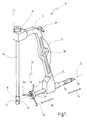
- FIG. 1shows a perspective side view of a device according to the invention
- FIG. 2shows the device from FIG. 1 in a partially sectioned side view, with no drilling tool received in the guide sleeve;
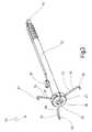
- FIG. 3shows an enlarged view of the guide sleeve and of the fixing device protruding distally from the guide sleeve as in FIG. 1 ;
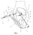
- FIG. 4shows a situation during the formation of a second bore in the reconstruction of an anterior cruciate ligament, with the whole device according to the invention from FIG. 1 being able to be seen;
- FIG. 5shows a view comparable to that of FIG. 4 , with the frame and the rod-shaped body having been withdrawn;
- FIG. 6shows a view comparable to that of FIG. 5 , with a tendon replacement having been pushed into the first bore in the bone and a transverse pin having been inserted into the second bore.
- a device for guiding a drilling tool for forming a second bore in a boneis designated in its entirety by reference number 10 .
- the device 10has a frame 12 which, in this illustrative embodiment, is designed as an L-shaped bracket 13 .
- a rod-shaped body 16Arranged at a first end 14 of the frame 12 there is a rod-shaped body 16 which can be inserted into an already existing first bore in a bone, as will be described in more detail below with reference to FIGS. 4 to 6 .
- the rod-shaped body 16has a circular cross section.
- An opening 20 in the form of a continuous transverse boreis present at a distal end 18 of the rod-shaped body 16 .
- the rod-shaped body 16is hollow.
- the rod-shaped body 16is connected releasably to the first end 14 of the frame 12 by a screw 22 .
- a guide sleeve 26is received displaceably in a second end 24 of the frame 12 .
- a channel 28extends through the guide sleeve 26 , as is shown in particular in the sectional view in FIG. 2 .
- a drilling tool 92can be received in the channel 28 , as can be seen from FIG. 1 .
- the guide sleeve 26has a locking screw 30 .
- the locking screw 30is used to fix a drilling wire or drilling tool 92 which is received in the channel 28 of the guide sleeve 26 and which can be displaced to and fro.
- the guide sleeve 26itself is also displaceable to and fro along its longitudinal axis 32 in the second end 24 , as is indicated by arrows 34 , 36 in FIG. 1 .
- a clamping deviceis used to lock the guide sleeve 26 by clamping.
- a movable clamping bar 38is arranged in the L-shaped bracket 13 of the frame 12 . It can be actuated by a lever 40 , which is arranged on an outer face of the frame 12 and is thus easy for an operator to actuate. A cam 41 of the lever 40 rests on the upper end of the clamping bar 38 .
- the lower end of the clamping bar 38is connected to a pivot lever 44 , of which one limb 46 can be brought into clamping connection with the outer face of the guide sleeve 26 .
- Pressing the lever 40causes the limb 46 to bear on the guide sleeve 26 , as a result of which the displacement of the guide sleeve 26 in the direction indicated by the arrow 34 is blocked.
- the guide sleeve 26is oriented in such a way that its longitudinal axis 32 is oriented towards a location 42 lying approximately at the centre of the opening 20 in the rod-shaped body 16 .
- Said opening 20is arranged at a distal end area 18 of the rod-shaped body 16 .
- a guide wire or drilling toolWhen, as will be described in more detail below, a guide wire or drilling tool is pushed into the guide sleeve 26 , it will be precisely directed along the longitudinal axis 32 to the opening 20 at the distal end 18 of the rod-shaped body 16 .
- a distally protruding fixing device 50is arranged on the guide sleeve 26 .
- the fixing device 50is arranged on a distal end of the guide sleeve 26 .
- the fixing device 50has a holder body 58 on which three guide elements 52 , 54 , 56 are arranged.
- the holder body 58is designed as an annular ring-shaped element 60 .
- an opening 62is used to secure the holder body 58 on the distal end of the guide sleeve.
- the fixing elements 52 , 54 , 56are designed as radially protruding legs 64 , 66 , 68 . Ends 65 , 67 , 69 of the fixing elements 52 , 54 , 56 are hook-shaped.
- the fixing elements 52 , 54 , 56 designed as legs 64 , 66 , 68are distributed uniformly about the circumference of the holder body 58 , i.e. the fixing elements 52 , 54 , 56 are each mutually offset by approximately 120° on the holder body 58 .
- the holder body 58is connected to the guide sleeve 26 via a ball joint 70 , as can be seen from the sectional view in FIG. 2 .
- Different angle settings of the holder body relative to the longitudinal direction of the guide sleeve 26can thus be achieved.
- the spider-like legs 64 , 66 , 68by virtue of their elasticity, permit more precise adjustment to uneven surfaces of the body.
- FIG. 4is a highly schematic representation of a human knee joint 72 .
- the knee joint 72is a connecting joint between the tibia (shin bone) 74 and the femur (thigh bone) 76 . Lying at the centre of the human knee there are two intersecting ligaments extending from the tibia 74 to the femur 76 , namely the posterior cruciate ligament 78 and the anterior cruciate ligament, which is not shown here, and which is to be replaced by an implant.
- a surgical instrumentis used first to produce a first bore 80 which extends both through the tibia 74 and also into the femur 76 .
- the orientationcorresponds approximately to the natural extent of the anterior cruciate ligament that is to be replaced.
- the bore 80in most cases continues as far as the outer face of the femur 76 by way of a channel of small diameter.
- the rod-shaped body 16 of the device 10is inserted into the first bore 80 .
- the guide sleeve 26 arranged at the second end 24 of the frame 12is then targeted by the operator at an anatomically favourable site, with the fixing device 50 protruding distally from the guide sleeve 26 .
- the guide sleeve 26 with the fixing device 50is then displaced by the operator in the direction indicated by an arrow 82 until the hook-shaped ends 65 , 67 , 69 of the fixing elements 52 , 54 , 56 reach the body 86 of the patient in the area where the second bore 84 is to be formed.
- the fixing device 50is able to adapt to irregularities of the patient's body, which is uneven in the area of the knee joint. In doing so, the orientation of the guide sleeve 26 does not change again.
- the guide sleeve 26remains in this position of longitudinal displacement.
- the rod-shaped body 16engaged in the first bore, and the L-shaped bracket 13 exert the necessary contact pressure by means of the L-shaped bracket 13 being spread slightly away from the rod-shaped body.
- the second bore 84can thus be formed with great precision.
- a drilling wire 90is first driven through the channel 28 of the guide sleeve 26 and through the skin 88 and tissue 89 into the femur 76 , specifically until the drilling wire 90 passes through the opening 20 in the rod-shaped body 16 located in the first bore 80 , as is shown in FIG. 4 .
- a hollow drill 92is then driven through the channel 28 , over the drilling wire 90 , into the femur 76 and lies exactly in line with the opening 20 in the rod-shaped body 16 .
- the clamped connection between L-shaped bracket 13 and guide sleeve 26is released and the rod-shaped body 16 and the frame 12 are withdrawn.
- the guide sleeve 26thus remains in the hollow drill 92 on or in the body.
- the fixing device 50the guide sleeve 26 remains on the body, protruding therefrom.
- the hollow drill 92is drawn back until the first bore 80 lies free.
- a prepared tendon serving as cruciate ligament replacement 94is drawn in as a double loop into the first bore 80 with the aid of a pulling thread.
- the pulling thread 96is then fixed on the outside of the body 86 using a fixing button 98 .
- the drilling tool 92is now removed from the guide sleeve 26 , and a transverse pin 100 is inserted through the channel 28 in the guide sleeve 26 and into the second bore 84 .
- the transverse pin 100By means of the transverse pin 100 , the cruciate ligament replacement 94 is fixed against being pulled out of the first bore 80 .
- the ends of the cruciate ligament replacement 94are fixed in the first bore 80 , e.g. by a bone dowel or further fixing button (not shown here).
Landscapes
- Health & Medical Sciences (AREA)
- Surgery (AREA)
- Orthopedic Medicine & Surgery (AREA)
- Life Sciences & Earth Sciences (AREA)
- Engineering & Computer Science (AREA)
- Medical Informatics (AREA)
- Oral & Maxillofacial Surgery (AREA)
- Dentistry (AREA)
- Rheumatology (AREA)
- Biomedical Technology (AREA)
- Heart & Thoracic Surgery (AREA)
- Nuclear Medicine, Radiotherapy & Molecular Imaging (AREA)
- Molecular Biology (AREA)
- Animal Behavior & Ethology (AREA)
- General Health & Medical Sciences (AREA)
- Public Health (AREA)
- Veterinary Medicine (AREA)
- Surgical Instruments (AREA)
- Drilling And Boring (AREA)
Abstract
Description
Claims (8)
Applications Claiming Priority (3)
| Application Number | Priority Date | Filing Date | Title |
|---|---|---|---|
| DE102006062382.7 | 2006-12-22 | ||
| DE102006062382 | 2006-12-22 | ||
| DE200610062382DE102006062382B4 (en) | 2006-12-22 | 2006-12-22 | Device for guiding a drilling tool for introducing a second bore in a bone |
Publications (2)
| Publication Number | Publication Date |
|---|---|
| US20080154271A1 US20080154271A1 (en) | 2008-06-26 |
| US9005212B2true US9005212B2 (en) | 2015-04-14 |
Family
ID=39271179
Family Applications (1)
| Application Number | Title | Priority Date | Filing Date |
|---|---|---|---|
| US11/962,581Expired - Fee RelatedUS9005212B2 (en) | 2006-12-22 | 2007-12-21 | Device for guiding a drilling tool for forming a second bore in a bone |
Country Status (4)
| Country | Link |
|---|---|
| US (1) | US9005212B2 (en) |
| EP (1) | EP1935352B1 (en) |
| AT (1) | ATE444023T1 (en) |
| DE (2) | DE102006062382B4 (en) |
Cited By (2)
| Publication number | Priority date | Publication date | Assignee | Title |
|---|---|---|---|---|
| US20170252048A1 (en)* | 2016-03-01 | 2017-09-07 | Karl Storz Gmbh & Co. Kg | Target apparatus for aligning a surgical drilling instrument |
| USD877903S1 (en)* | 2017-06-16 | 2020-03-10 | Karl Storz Se & Co. Kg | Target apparatus |
Families Citing this family (49)
| Publication number | Priority date | Publication date | Assignee | Title |
|---|---|---|---|---|
| US8177841B2 (en) | 2000-05-01 | 2012-05-15 | Arthrosurface Inc. | System and method for joint resurface repair |
| US6610067B2 (en) | 2000-05-01 | 2003-08-26 | Arthrosurface, Incorporated | System and method for joint resurface repair |
| US7678151B2 (en) | 2000-05-01 | 2010-03-16 | Ek Steven W | System and method for joint resurface repair |
| US6520964B2 (en) | 2000-05-01 | 2003-02-18 | Std Manufacturing, Inc. | System and method for joint resurface repair |
| US7163541B2 (en) | 2002-12-03 | 2007-01-16 | Arthrosurface Incorporated | Tibial resurfacing system |
| US7901408B2 (en) | 2002-12-03 | 2011-03-08 | Arthrosurface, Inc. | System and method for retrograde procedure |
| US7914545B2 (en) | 2002-12-03 | 2011-03-29 | Arthrosurface, Inc | System and method for retrograde procedure |
| US8388624B2 (en) | 2003-02-24 | 2013-03-05 | Arthrosurface Incorporated | Trochlear resurfacing system and method |
| AU2004293042A1 (en) | 2003-11-20 | 2005-06-09 | Arthrosurface, Inc. | Retrograde delivery of resurfacing devices |
| WO2006004885A2 (en) | 2004-06-28 | 2006-01-12 | Arthrosurface, Inc. | System for articular surface replacement |
| US7828853B2 (en) | 2004-11-22 | 2010-11-09 | Arthrosurface, Inc. | Articular surface implant and delivery system |
| US9358029B2 (en) | 2006-12-11 | 2016-06-07 | Arthrosurface Incorporated | Retrograde resection apparatus and method |
| EP2262448A4 (en) | 2008-03-03 | 2014-03-26 | Arthrosurface Inc | Bone resurfacing system and method |
| US8313487B2 (en) | 2008-06-24 | 2012-11-20 | Extremity Medical Llc | Fixation system, an intramedullary fixation assembly and method of use |
| US8328806B2 (en) | 2008-06-24 | 2012-12-11 | Extremity Medical, Llc | Fixation system, an intramedullary fixation assembly and method of use |
| US9289220B2 (en) | 2008-06-24 | 2016-03-22 | Extremity Medical Llc | Intramedullary fixation assembly and method of use |
| US9044282B2 (en) | 2008-06-24 | 2015-06-02 | Extremity Medical Llc | Intraosseous intramedullary fixation assembly and method of use |
| US9017329B2 (en) | 2008-06-24 | 2015-04-28 | Extremity Medical, Llc | Intramedullary fixation assembly and method of use |
| US8343199B2 (en) | 2008-06-24 | 2013-01-01 | Extremity Medical, Llc | Intramedullary fixation screw, a fixation system, and method of fixation of the subtalar joint |
| US8303589B2 (en) | 2008-06-24 | 2012-11-06 | Extremity Medical Llc | Fixation system, an intramedullary fixation assembly and method of use |
| US20100121375A1 (en)* | 2008-11-13 | 2010-05-13 | Pandya Rajiv D | Suture anchoring system and method |
| WO2010121250A1 (en) | 2009-04-17 | 2010-10-21 | Arthrosurface Incorporated | Glenoid resurfacing system and method |
| AU2010236182A1 (en) | 2009-04-17 | 2011-11-24 | Arthrosurface Incorporated | Glenoid resurfacing system and method |
| US10945743B2 (en) | 2009-04-17 | 2021-03-16 | Arthrosurface Incorporated | Glenoid repair system and methods of use thereof |
| EP2542165A4 (en)* | 2010-03-05 | 2015-10-07 | Arthrosurface Inc | Tibial resurfacing system and method |
| US9066716B2 (en) | 2011-03-30 | 2015-06-30 | Arthrosurface Incorporated | Suture coil and suture sheath for tissue repair |
| DE102011106729A1 (en)* | 2011-06-28 | 2013-01-03 | Karl Storz Gmbh & Co. Kg | Device for targeting and inserting drilling channels into the tibia |
| EP2804565B1 (en) | 2011-12-22 | 2018-03-07 | Arthrosurface Incorporated | System for bone fixation |
| WO2014008126A1 (en) | 2012-07-03 | 2014-01-09 | Arthrosurface Incorporated | System and method for joint resurfacing and repair |
| US9492200B2 (en) | 2013-04-16 | 2016-11-15 | Arthrosurface Incorporated | Suture system and method |
| US10624748B2 (en) | 2014-03-07 | 2020-04-21 | Arthrosurface Incorporated | System and method for repairing articular surfaces |
| US9931219B2 (en) | 2014-03-07 | 2018-04-03 | Arthrosurface Incorporated | Implant and anchor assembly |
| US11607319B2 (en) | 2014-03-07 | 2023-03-21 | Arthrosurface Incorporated | System and method for repairing articular surfaces |
| BR112017008135B1 (en)* | 2014-10-19 | 2022-11-16 | T.A.G. Medical Devices - Agriculture Cooperative Ltd | SET INCLUDING A GUIDANCE SYSTEM AND BONE MATERIAL REMOVAL DEVICE AND METHOD FOR DRILLING A BONE TUNNEL INTO A BONE |
| JP7007190B2 (en) | 2015-04-09 | 2022-01-24 | ティー.エー.ジー. メディカル デヴァイシス-アグリカルチャー コーポラティヴ リミテッド | Bone material remover and how to use it |
| EP3799806A1 (en) | 2016-02-11 | 2021-04-07 | T.A.G. Medical Devices - Agriculture Cooperative Ltd. | Bone material removal device |
| US11376079B2 (en) | 2016-02-19 | 2022-07-05 | Rajiv D. Pandya | System and technique for accessing extra articular lesions or abnormalities or intra osseous lesions or bone marrow lesions |
| US11419684B2 (en) | 2016-02-19 | 2022-08-23 | Rajiv D. Pandya | System and technique for accessing extra articular lesions or abnormalities or intra osseous lesions or bone marrow lesions |
| US9925010B2 (en) | 2016-02-19 | 2018-03-27 | Rajiv D. Pandya | System and technique for accessing extra articular lesions or abnormalities or intra osseous lesions or bone marrow lesions |
| US10064632B2 (en) | 2016-02-19 | 2018-09-04 | Rajiv D. Pandya | System and technique for accessing extra articular lesions or abnormalities or intra osseous lesions or bone marrow lesions |
| EP3448274B1 (en) | 2016-04-24 | 2024-05-15 | T.A.G. Medical Products Corporation Ltd. | Guiding device |
| US11160663B2 (en) | 2017-08-04 | 2021-11-02 | Arthrosurface Incorporated | Multicomponent articular surface implant |
| IL280574B2 (en) | 2018-08-01 | 2025-08-01 | Tag Medical Devices Agriculture Coop Ltd | Adjustable drilling device and method for using the same |
| WO2020186099A1 (en) | 2019-03-12 | 2020-09-17 | Arthrosurface Incorporated | Humeral and glenoid articular surface implant systems and methods |
| US11357517B1 (en) | 2019-04-25 | 2022-06-14 | Nirav H. Amin | System and method for creating graft tunnels in bone |
| IT201900018869A1 (en)* | 2019-10-15 | 2021-04-15 | Medacta Int Sa | SURGICAL DEVICE |
| US11963688B2 (en) | 2021-11-20 | 2024-04-23 | Panorthopaedics, Inc. | Device adapted for lateral engagement of an elongated member |
| US20250017719A1 (en) | 2023-07-12 | 2025-01-16 | Integrity Medical Services Inc. | Tissue repair devices, systems, and methods |
| US12433583B1 (en) | 2024-05-31 | 2025-10-07 | Integrity Medical Services Inc. | Suture passer devices, systems, and methods |
Citations (11)
| Publication number | Priority date | Publication date | Assignee | Title |
|---|---|---|---|---|
| DE3312250A1 (en) | 1983-04-05 | 1984-10-11 | Walter Prof.Dr. 2300 Kiel Blauth | Targeting device |
| US4722331A (en) | 1985-09-03 | 1988-02-02 | Fox James M | Orthopaedic tool guide |
| US5688284A (en)* | 1996-09-20 | 1997-11-18 | Medicinelodge, Inc. | Variable angle drill guide and ligament fixation method |
| US5893878A (en)* | 1997-04-24 | 1999-04-13 | Pierce; Javin | Micro traumatic tissue manipulator apparatus |
| US6254605B1 (en) | 1990-07-16 | 2001-07-03 | Stephen M. Howell | Tibial guide |
| US6595999B2 (en)* | 2001-04-27 | 2003-07-22 | Sulzer Orthopedics Ltd. | Drilling jig for the determination of the axis of a femur head prosthesis |
| US20040087953A1 (en) | 2002-05-15 | 2004-05-06 | Wamis Singhatat | Cross-pin graft fixation, instruments, and methods |
| US6994725B1 (en) | 2000-10-03 | 2006-02-07 | Medicinelodge, Inc. | Method and apparatus for reconstructing a ligament |
| US20060069394A1 (en) | 2004-09-29 | 2006-03-30 | Andreas Weiler | Device for guiding a drilling tool |
| EP1714619A1 (en) | 2005-04-22 | 2006-10-25 | Karl Storz GmbH & Co. KG | Instrument for making a bore in a bone |
| US20070191852A1 (en) | 2006-01-27 | 2007-08-16 | Sdgi Holdings, Inc. | Osteochondral implant fixation method |
Family Cites Families (2)
| Publication number | Priority date | Publication date | Assignee | Title |
|---|---|---|---|---|
| US6113604A (en)* | 1997-01-14 | 2000-09-05 | Ethicon, Inc. | Method and apparatus for fixing a graft in a bone tunnel |
| DE19811354B4 (en)* | 1998-03-16 | 2007-07-19 | Intraplant Ag | Device for osteosynthesis and adapted to the device fixation pin for osteosynthesis |
- 2006
- 2006-12-22DEDE200610062382patent/DE102006062382B4/ennot_activeExpired - Fee Related
- 2007
- 2007-12-20DEDE200750001618patent/DE502007001618D1/enactiveActive
- 2007-12-20EPEP20070024698patent/EP1935352B1/ennot_activeNot-in-force
- 2007-12-20ATAT07024698Tpatent/ATE444023T1/ennot_activeIP Right Cessation
- 2007-12-21USUS11/962,581patent/US9005212B2/ennot_activeExpired - Fee Related
Patent Citations (13)
| Publication number | Priority date | Publication date | Assignee | Title |
|---|---|---|---|---|
| DE3312250A1 (en) | 1983-04-05 | 1984-10-11 | Walter Prof.Dr. 2300 Kiel Blauth | Targeting device |
| US4722331A (en) | 1985-09-03 | 1988-02-02 | Fox James M | Orthopaedic tool guide |
| US6254605B1 (en) | 1990-07-16 | 2001-07-03 | Stephen M. Howell | Tibial guide |
| US5688284A (en)* | 1996-09-20 | 1997-11-18 | Medicinelodge, Inc. | Variable angle drill guide and ligament fixation method |
| US5893878A (en)* | 1997-04-24 | 1999-04-13 | Pierce; Javin | Micro traumatic tissue manipulator apparatus |
| US6994725B1 (en) | 2000-10-03 | 2006-02-07 | Medicinelodge, Inc. | Method and apparatus for reconstructing a ligament |
| US6595999B2 (en)* | 2001-04-27 | 2003-07-22 | Sulzer Orthopedics Ltd. | Drilling jig for the determination of the axis of a femur head prosthesis |
| US20040087953A1 (en) | 2002-05-15 | 2004-05-06 | Wamis Singhatat | Cross-pin graft fixation, instruments, and methods |
| US20060069394A1 (en) | 2004-09-29 | 2006-03-30 | Andreas Weiler | Device for guiding a drilling tool |
| EP1642538A2 (en) | 2004-09-29 | 2006-04-05 | Karl Storz GmbH & Co. KG | Device for guiding a drilling tool |
| EP1714619A1 (en) | 2005-04-22 | 2006-10-25 | Karl Storz GmbH & Co. KG | Instrument for making a bore in a bone |
| US20070123902A1 (en) | 2005-04-22 | 2007-05-31 | Sascha Berberich | Device for forming a drill hole in bone |
| US20070191852A1 (en) | 2006-01-27 | 2007-08-16 | Sdgi Holdings, Inc. | Osteochondral implant fixation method |
Cited By (3)
| Publication number | Priority date | Publication date | Assignee | Title |
|---|---|---|---|---|
| US20170252048A1 (en)* | 2016-03-01 | 2017-09-07 | Karl Storz Gmbh & Co. Kg | Target apparatus for aligning a surgical drilling instrument |
| US10531881B2 (en)* | 2016-03-01 | 2020-01-14 | Karl Storz Se & Co. Kg | Target apparatus for aligning a surgical drilling instrument |
| USD877903S1 (en)* | 2017-06-16 | 2020-03-10 | Karl Storz Se & Co. Kg | Target apparatus |
Also Published As
| Publication number | Publication date |
|---|---|
| DE102006062382A1 (en) | 2008-06-26 |
| EP1935352B1 (en) | 2009-09-30 |
| ATE444023T1 (en) | 2009-10-15 |
| DE102006062382B4 (en) | 2014-08-07 |
| EP1935352A1 (en) | 2008-06-25 |
| DE502007001618D1 (en) | 2009-11-12 |
| US20080154271A1 (en) | 2008-06-26 |
Similar Documents
| Publication | Publication Date | Title |
|---|---|---|
| US9005212B2 (en) | Device for guiding a drilling tool for forming a second bore in a bone | |
| JP4315804B2 (en) | Apparatus and method for reshaping a ligament | |
| CN104042369B (en) | Shin bone test specimen apparatus for the biasing that shapes | |
| CN104042308B (en) | Shin bone orthopaedic instrumentation for the biasing that shapes | |
| JP5265173B2 (en) | Ligament repair method and repair device | |
| US6267767B1 (en) | Instrumentarium and method for implanting a cruciate ligament replacement in a knee joint | |
| JP5325257B2 (en) | Apparatus and method for reconstructing a ligament | |
| JP4372383B2 (en) | Tools used for insertion of waist cup | |
| US7972341B2 (en) | Device for forming a drill hole in bone | |
| US8480676B2 (en) | Bone tamp apparatus and method | |
| CN104095664B (en) | Distal femur clamp assembly and the distal femur cutting device with this assembly | |
| US9089349B2 (en) | Device for introducing multiple drilled channels in a bone | |
| KR20090082511A (en) | Device for Bone Surgery | |
| US8430884B2 (en) | Femoral guide for ACL repair having selectively deployable femoral surface engagement member | |
| JP2019502523A (en) | Fracture repair device and method | |
| JP2021506553A (en) | Minimally invasive hip arthroplasty technology and equipment | |
| US20230115148A1 (en) | Soft tissue implant systems, instruments, and related methods | |
| CN222444237U (en) | Posterior cruciate ligament positioner | |
| KR101890150B1 (en) | Guide for reconstruction of cruciate ligaments |
Legal Events
| Date | Code | Title | Description |
|---|---|---|---|
| AS | Assignment | Owner name:KARL STORZ GMBH & CO. KG, GERMANY Free format text:ASSIGNMENT OF ASSIGNORS INTEREST;ASSIGNORS:BERBERICH, SASCHA;SAUER, MICHAEL;SIGNING DATES FROM 20080121 TO 20080207;REEL/FRAME:020674/0650 Owner name:KARL STORZ GMBH & CO. KG, GERMANY Free format text:ASSIGNMENT OF ASSIGNORS INTEREST;ASSIGNORS:BERBERICH, SASCHA;SAUER, MICHAEL;REEL/FRAME:020674/0650;SIGNING DATES FROM 20080121 TO 20080207 | |
| FEPP | Fee payment procedure | Free format text:PAYOR NUMBER ASSIGNED (ORIGINAL EVENT CODE: ASPN); ENTITY STATUS OF PATENT OWNER: LARGE ENTITY | |
| STCF | Information on status: patent grant | Free format text:PATENTED CASE | |
| AS | Assignment | Owner name:KARL STORZ SE & CO. KG, GERMANY Free format text:CHANGE OF NAME;ASSIGNOR:KARL STORZ GMBH & CO. KG;REEL/FRAME:045373/0627 Effective date:20170911 | |
| MAFP | Maintenance fee payment | Free format text:PAYMENT OF MAINTENANCE FEE, 4TH YEAR, LARGE ENTITY (ORIGINAL EVENT CODE: M1551); ENTITY STATUS OF PATENT OWNER: LARGE ENTITY Year of fee payment:4 | |
| FEPP | Fee payment procedure | Free format text:MAINTENANCE FEE REMINDER MAILED (ORIGINAL EVENT CODE: REM.); ENTITY STATUS OF PATENT OWNER: LARGE ENTITY | |
| LAPS | Lapse for failure to pay maintenance fees | Free format text:PATENT EXPIRED FOR FAILURE TO PAY MAINTENANCE FEES (ORIGINAL EVENT CODE: EXP.); ENTITY STATUS OF PATENT OWNER: LARGE ENTITY | |
| STCH | Information on status: patent discontinuation | Free format text:PATENT EXPIRED DUE TO NONPAYMENT OF MAINTENANCE FEES UNDER 37 CFR 1.362 | |
| FP | Lapsed due to failure to pay maintenance fee | Effective date:20230414 |