US9004883B2 - Low noise high efficiency solenoid pump - Google Patents
Low noise high efficiency solenoid pumpDownload PDFInfo
- Publication number
- US9004883B2 US9004883B2US13/078,085US201113078085AUS9004883B2US 9004883 B2US9004883 B2US 9004883B2US 201113078085 AUS201113078085 AUS 201113078085AUS 9004883 B2US9004883 B2US 9004883B2
- Authority
- US
- United States
- Prior art keywords
- piston
- disposed
- pump
- section
- housing
- Prior art date
- Legal status (The legal status is an assumption and is not a legal conclusion. Google has not performed a legal analysis and makes no representation as to the accuracy of the status listed.)
- Expired - Fee Related, expires
Links
Images

Classifications
- F—MECHANICAL ENGINEERING; LIGHTING; HEATING; WEAPONS; BLASTING
- F04—POSITIVE - DISPLACEMENT MACHINES FOR LIQUIDS; PUMPS FOR LIQUIDS OR ELASTIC FLUIDS
- F04B—POSITIVE-DISPLACEMENT MACHINES FOR LIQUIDS; PUMPS
- F04B11/00—Equalisation of pulses, e.g. by use of air vessels; Counteracting cavitation
- F04B11/005—Equalisation of pulses, e.g. by use of air vessels; Counteracting cavitation using two or more pumping pistons
- F04B11/0058—Equalisation of pulses, e.g. by use of air vessels; Counteracting cavitation using two or more pumping pistons with piston speed control
- F—MECHANICAL ENGINEERING; LIGHTING; HEATING; WEAPONS; BLASTING
- F04—POSITIVE - DISPLACEMENT MACHINES FOR LIQUIDS; PUMPS FOR LIQUIDS OR ELASTIC FLUIDS
- F04B—POSITIVE-DISPLACEMENT MACHINES FOR LIQUIDS; PUMPS
- F04B17/00—Pumps characterised by combination with, or adaptation to, specific driving engines or motors
- F04B17/03—Pumps characterised by combination with, or adaptation to, specific driving engines or motors driven by electric motors
- F04B17/04—Pumps characterised by combination with, or adaptation to, specific driving engines or motors driven by electric motors using solenoids
- F04B17/046—Pumps characterised by combination with, or adaptation to, specific driving engines or motors driven by electric motors using solenoids the fluid flowing through the moving part of the motor
Definitions
- the present disclosurerelates to solenoid pumps and more particularly to a low noise, high efficiency solenoid pump.
- engine start stopThis operational scheme generally involves shutting off the gasoline, Diesel or flex fuel engine whenever the vehicle is stopped in traffic, that is, whenever the vehicle is in gear but stationary for longer than a short, relatively predictable time, such as occurs at a traffic light or in stop-and-go traffic.
- Solenoid pumpshave become popular in engine start stop applications, not only for their lower cost but also because their generally somewhat limited flow and pressure output is a good match for engine start stop transmission applications.
- the present inventionprovides a low noise, high efficiency solenoid pump.
- the solenoid pumpincludes a housing containing a hollow electromagnetic coil. Within the coil resides a sealed pump assembly defining a tubular body having a pair of opposed ends which respectively include an inlet or suction port and an outlet or pressure port and within which a plunger or piston resides.
- the pistonis biased in opposite directions by a pair of opposed compression springs. A first compression spring limits and snubs travel of the piston during the suction or return stroke (and assists the pumping stroke) and a second compression spring limits and snubs travel of the piston during the pumping stroke and returns the piston after the pumping stroke.
- the pistonincludes a first check valve that opens to allow hydraulic fluid (transmission oil) into a pumping chamber during the suction stroke and closes during the pumping stroke to cause fluid to be pumped out of the pumping chamber.
- a second check valvealigned with the first check valve, opens to allow pumped (pressurized) fluid to exit the pumping chamber and the pump body through the outlet or pressure port and closes to inhibit reverse flow.
- the spring rates of the two compression springs and the mass of the pistonare chosen to provide a mechanical system having a harmonic frequency of vibration that coincides closely with the frequency of the impulses applied to the electromagnetic coil of the solenoid to reciprocate the piston.
- the pistonis driven at and reciprocates or oscillates at its damped natural frequency of vibration, thereby reducing energy consumption and rendering the solenoid highly efficient.
- the compression springsreduce the steady and repeated noise pulses associated with the direction reversal of the piston at the end of its strokes by absorbing energy from the piston and relatively slowly reversing its direction of translation.
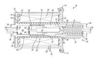
- FIG. 1is a full sectional view of a solenoid pump according to the present invention.
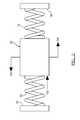
- FIG. 2is a diagrammatic view of the forces acting upon a piston assembly of a solenoid pump according to the present invention.
- the solenoid pump 10includes a generally tubular or cylindrical deep drawn typically metal housing 12 which is closed at one end by a circular disc or end plate assembly 14 suitably secured to an end flange 16 or similar structure of the tubular housing 12 by any suitable fastening means such as threaded fasteners 17 .
- the end plate assembly 14also includes a tubular extension 18 .
- the tubular housing 12receives an electromagnetic coil 20 which is wound on an insulating bobbin 22 .
- At each end of the bobbin 22is a circular metal retaining disc 24 which also functions to concentrate the magnetic flux of the electromagnetic coil 20 .
- An electrical lead or leads 26pass through the tubular housing 12 in a suitable insulating feed-through 28 and provide electrical energy to the electromagnetic coil 20 .
- a pump assembly 30Concentrically disposed within the hollow bobbin 22 of the electromagnetic coil 20 is a pump assembly 30 which includes a fluid tight elongate pump body 32 .
- the pump body 32for ease of manufacturing, preferably comprises two aligned sections.
- a first generally tubular elongate section 34is received within the tubular extension 18 and defines an inlet port 36 surrounded by an interior shoulder or surface 38 and an exterior shoulder or flange 40 that is engaged by a complementary groove or channel 42 formed in the circular disc or end plate assembly 14 .
- Sealingly and axially aligned with the first tubular section 34is a second tubular section 44 defining a pressurized fluid outlet chamber 46 and an exterior shoulder or flange 48 that is engaged by the adjacent circular retaining disc 24 .
- Aligned with and sealed to the second tubular section 44is an outlet housing or section 52 which defines an outlet port 54 which is aligned with the fluid outlet chamber 46 .
- the first tubular elongate section 34 and the second tubular section 44define an elongate, hollow, fluid tight, cylindrical pumping chamber 60 .
- a piston assembly 62Slidably disposed within the pumping chamber 60 is a piston assembly 62 .
- the piston assembly 62preferably includes a first, ferrous, i.e., magnetic, plunger or armature portion 64 .
- the first compression spring 70has a spring rate selected in accordance with the design constraints described below.
- the plunger or armature portion 64also defines a first axial throat or passageway 72 which provides fluid communication between the inlet port 36 and an enlarged interior axial chamber or passageway 74 within the armature or plunger portion 64 .
- the piston assembly 62preferably also includes a second, non-magnetic body or member portion 76 , which may be either metallic or non-metallic, through which the axial chamber or passageway 74 also extends. If desired, however, the piston assembly 62 may be a single piece, single material component.
- the second body or member portion 76defines a second axial throat or passageway 78 aligned with the passageway 74 and the first axial throat or passageway 72 which is terminated and selectively closed off by a first one-way check or reed valve 82 which is self-biased against a circular shoulder or ridge 86 to close off the axial passageway 74 .
- the first one-way check or reed valve 82may be a ball check or poppet valve having a compression spring (all not illustrated).
- a second compression spring 90concentrically disposed about the piston assembly 62 engages a shoulder 92 on the first plunger or armature portion 64 and biases the piston assembly 62 to the right as illustrated in FIG.
- the second compression spring 90has a spring rate selected in accordance with the design constraints described below. Typically, though not necessarily, the second compression spring 90 will be shorter than and have a higher spring rate than the first compression spring 70 .
- a second one-way check or reed valve 94which is self-biased against a circular shoulder or ridge 98 to selectively close off fluid communication between the pumping chamber 60 and the pressurized fluid outlet chamber 46 .
- the second one-way check or reed valve 94may be a ball check or poppet valve having a compression spring (all not illustrated).
- the arrow 100 pointing to the leftrepresents the pumping force (F sol ) on the piston assembly 62 exerted by the electromagnetic coil 20
- the arrow 102 pointing to the rightrepresents the damping force exerted on the piston assembly 62
- the arrow 104 also pointing to the rightrepresents the force or resistance (F hyd ) exerted on the piston assembly by the hydraulic fluid.
- the natural frequency (resonance) of vibration of a mechanical systemis given by
- ⁇c 2 ⁇ k ⁇ ⁇ m ( 3 )
- mthe mass of the piston assembly 62
- kthe spring rate
- cthe damping coefficient.
- the operation of the solenoid pump 10is straightforward. Assuming the solenoid pump 10 is filled with a fluid such as hydraulic fluid or transmission oil, when the electromagnetic coil 20 is energized, the piston assembly 62 translates to the left in FIG. 1 , assisted by the force of the first compression spring 70 and resisted by the force of the second compression spring 90 , drawing in fluid through the inlet port 36 and forcing fluid at the left end of the piston assembly 62 past the second poppet or check valve 94 and out the outlet port 54 . When the electromagnetic coil 20 is de-energized, the piston assembly 62 translates to the right, assisted by the force of the second compression spring 90 and resisted by the force of the first compression spring 70 .
- a fluidsuch as hydraulic fluid or transmission oil
- the first poppet or check valve 82opens and fluid flows from the right end of the pumping chamber 60 , through the axial passageway 74 , past the first poppet valve 82 and into the left end of the pumping chamber 60 .
- the pumping cycleis then repeated as the electromagnetic coil 20 is re-energized.
- the mass of the piston assembly 62 and the forces of the first and the second compression springs 70 and 90 applied to itare chosen so that at a nominal, desired output flow and pressure, the mechanical system of the piston assembly 62 and the compression springs 70 and 90 operate or reciprocate at their damped natural frequency of vibration or a harmonic thereof as set forth above. Furthermore, these variables are chosen so that in normal operation, the piston assembly 62 does not bottom out on the compression springs 70 and 90 , that is, the translation and reciprocation of the piston assembly 62 is such that it never causes the compression springs 70 and 90 to stack or become solid.
- a solenoid pump 10operates more quietly than conventional solenoid pumps because the piston assembly 62 is accelerated and decelerated not only more slowly but also in conformance with its natural frequency of vibration or a harmonic thereof.
- This operating modeprovides improved energy efficiency since the reciprocation of the piston assembly 62 conserves energy by operating at its damped natural frequency of vibration.
Landscapes
- Engineering & Computer Science (AREA)
- Mechanical Engineering (AREA)
- General Engineering & Computer Science (AREA)
- Physics & Mathematics (AREA)
- Fluid Mechanics (AREA)
- Electromagnetic Pumps, Or The Like (AREA)
Abstract
Description
m{umlaut over (x)}+b{dot over (x)}+kx=Fsol−Fhyd (1)
wherein the terms Fsol−Fhydrepresent the force generated by the
and the damping ratio (factor) is given by
wherein m is the mass of the
ωd=ωn(√{square root over (1−ζ2)}) (4)
Once the damping of the mechanical system is determined empirically or by experiment, it is necessary to achieve a “k” such that the system's damped natural frequency of vibration matches the excitation frequency of the
Hence,
And therefore,
An additional constraint that must be considered in the design of the
Fsol>kx+Fhyd (8)
Claims (15)
Priority Applications (3)
| Application Number | Priority Date | Filing Date | Title |
|---|---|---|---|
| US13/078,085US9004883B2 (en) | 2011-04-01 | 2011-04-01 | Low noise high efficiency solenoid pump |
| DE201210204994DE102012204994A1 (en) | 2011-04-01 | 2012-03-28 | Low-noise high-efficiency magnetic pump |
| CN201210089775.1ACN102734114B (en) | 2011-04-01 | 2012-03-30 | Low noise high efficiency solenoid pump |
Applications Claiming Priority (1)
| Application Number | Priority Date | Filing Date | Title |
|---|---|---|---|
| US13/078,085US9004883B2 (en) | 2011-04-01 | 2011-04-01 | Low noise high efficiency solenoid pump |
Publications (2)
| Publication Number | Publication Date |
|---|---|
| US20120251359A1 US20120251359A1 (en) | 2012-10-04 |
| US9004883B2true US9004883B2 (en) | 2015-04-14 |
Family
ID=46845298
Family Applications (1)
| Application Number | Title | Priority Date | Filing Date |
|---|---|---|---|
| US13/078,085Expired - Fee RelatedUS9004883B2 (en) | 2011-04-01 | 2011-04-01 | Low noise high efficiency solenoid pump |
Country Status (3)
| Country | Link |
|---|---|
| US (1) | US9004883B2 (en) |
| CN (1) | CN102734114B (en) |
| DE (1) | DE102012204994A1 (en) |
Cited By (10)
| Publication number | Priority date | Publication date | Assignee | Title |
|---|---|---|---|---|
| US20150139819A1 (en)* | 2012-05-16 | 2015-05-21 | Nuovo Pignone Srl | Electromagnetic actuator and inertia conservation device for a reciprocating compressor |
| US9490681B1 (en) | 2015-09-18 | 2016-11-08 | Ingersoll-Rand Company | Pulsed air to electric generator |
| US20180230982A1 (en)* | 2017-02-10 | 2018-08-16 | Lg Electronics Inc. | Linear compressor |
| US10424429B2 (en) | 2017-12-18 | 2019-09-24 | GM Global Technology Operations LLC | Long stroke linear solenoid |
| US10962014B2 (en)* | 2018-01-19 | 2021-03-30 | Hamilton Sundstrand Corporation | Valve-less variable displacement pump |
| US20220209637A1 (en)* | 2020-12-25 | 2022-06-30 | Nidec Corporation | Vibrating motor and haptic device |
| US20220209639A1 (en)* | 2020-12-25 | 2022-06-30 | Nidec Corporation | Vibrating motor and haptic device |
| US20220209638A1 (en)* | 2020-12-25 | 2022-06-30 | Nidec Corporation | Vibrating motor and haptic device |
| US11525605B2 (en)* | 2013-11-18 | 2022-12-13 | Bitzer Kuehlmaschinenbau Gmbh | Cooling circuit having a gas discharge unit removing gaseous refrigerant from a compressor feed line |
| US12166396B2 (en)* | 2020-07-10 | 2024-12-10 | Nidec Corporation | Vibration motor with bearing portion and air passage and air hole |
Families Citing this family (30)
| Publication number | Priority date | Publication date | Assignee | Title |
|---|---|---|---|---|
| GB0224986D0 (en) | 2002-10-28 | 2002-12-04 | Smith & Nephew | Apparatus |
| GB0325129D0 (en) | 2003-10-28 | 2003-12-03 | Smith & Nephew | Apparatus in situ |
| EP1905465B2 (en) | 2006-09-28 | 2013-11-27 | Smith & Nephew, Inc. | Portable wound therapy system |
| ES2715605T3 (en) | 2007-11-21 | 2019-06-05 | Smith & Nephew | Wound dressing |
| GB201015656D0 (en) | 2010-09-20 | 2010-10-27 | Smith & Nephew | Pressure control apparatus |
| US8567444B2 (en)* | 2010-10-08 | 2013-10-29 | GM Global Technology Operations LLC | Accumulator assembly |
| US9067003B2 (en) | 2011-05-26 | 2015-06-30 | Kalypto Medical, Inc. | Method for providing negative pressure to a negative pressure wound therapy bandage |
| BRPI1103647A2 (en)* | 2011-07-07 | 2013-07-02 | Whirlpool Sa | arrangement between linear compressor components |
| BRPI1103447A2 (en)* | 2011-07-19 | 2013-07-09 | Whirlpool Sa | spring bundle for compressor and spring bundled compressor |
| BRPI1104172A2 (en)* | 2011-08-31 | 2015-10-13 | Whirlpool Sa | linear compressor based on resonant oscillating mechanism |
| US9084845B2 (en) | 2011-11-02 | 2015-07-21 | Smith & Nephew Plc | Reduced pressure therapy apparatuses and methods of using same |
| AU2013237095B2 (en) | 2012-03-20 | 2017-10-05 | Smith & Nephew Plc | Controlling operation of a reduced pressure therapy system based on dynamic duty cycle threshold determination |
| US9427505B2 (en) | 2012-05-15 | 2016-08-30 | Smith & Nephew Plc | Negative pressure wound therapy apparatus |
| US9777716B2 (en)* | 2013-06-14 | 2017-10-03 | Richard Nelson | Dual displacement fluid level control pump |
| US9677519B2 (en) | 2013-08-27 | 2017-06-13 | Kia Motors Corporation | Device for decreasing fuel pulsation of LPG vehicle |
| DE102013112306A1 (en)* | 2013-11-08 | 2015-05-13 | Pierburg Gmbh | Magnetic pump for an auxiliary unit of a vehicle and method for controlling a magnetic pump for an auxiliary unit |
| US9506460B2 (en)* | 2014-02-10 | 2016-11-29 | Haier Us Appliance Solutions, Inc. | Linear compressor |
| US9518572B2 (en)* | 2014-02-10 | 2016-12-13 | Haier Us Appliance Solutions, Inc. | Linear compressor |
| US9322401B2 (en)* | 2014-02-10 | 2016-04-26 | General Electric Company | Linear compressor |
| US9429150B2 (en)* | 2014-02-10 | 2016-08-30 | Haier US Appliances Solutions, Inc. | Linear compressor |
| US20150226210A1 (en)* | 2014-02-10 | 2015-08-13 | General Electric Company | Linear compressor |
| DE102014218594A1 (en)* | 2014-09-16 | 2016-03-17 | Robert Bosch Gmbh | Piston pump with an area with a non-magnetic material in the magnetic circuit |
| JP6403529B2 (en)* | 2014-10-07 | 2018-10-10 | 住友重機械工業株式会社 | Movable body support structure, linear compressor, and cryogenic refrigerator |
| EP3237032B1 (en) | 2014-12-22 | 2024-08-07 | Smith & Nephew plc | Negative pressure wound therapy apparatus |
| WO2016106310A1 (en)* | 2014-12-22 | 2016-06-30 | Eaton Corporation | In-line valve |
| JP1546565S (en)* | 2015-08-19 | 2016-03-28 | ||
| CN107816547B (en)* | 2016-09-14 | 2019-05-24 | 上海汽车集团股份有限公司 | Shift fork control device and its bi-directional electromagnetic pump, control circuit |
| FR3078114B1 (en)* | 2018-02-16 | 2020-02-21 | Sauermann Industrie | OSCILLATING PISTON PUMP COMPRISING A MONOBLOCK STRUCTURAL ELEMENT HAVING A FIRST AND A SECOND HOLLOW TUBULAR BODY |
| DE102018130159A1 (en)* | 2018-11-28 | 2020-05-28 | Bayerische Motoren Werke Aktiengesellschaft | Cleaning unit |
| US11837423B2 (en)* | 2021-10-05 | 2023-12-05 | GM Global Technology Operations LLC | Arrangement and module for electrical contactor assemblies |
Citations (13)
| Publication number | Priority date | Publication date | Assignee | Title |
|---|---|---|---|---|
| US6323568B1 (en)* | 1999-01-17 | 2001-11-27 | Mnde Technologies, L.L.C. | Electromagnetic vibrator and pump including same |
| US6526746B1 (en)* | 2000-08-02 | 2003-03-04 | Ford Global Technologies, Inc. | On-board reductant delivery assembly |
| US6554588B1 (en)* | 1999-04-09 | 2003-04-29 | Ulka Srl | Composite piston for a vibration pump |
| US20040241017A1 (en)* | 2003-05-30 | 2004-12-02 | Buzzi S.R.L | Reciprocating electromagnetic micro-pump, particularly for small electrical appliances |
| US20050025638A1 (en)* | 2003-07-30 | 2005-02-03 | Invensys Controls Italy Srl | Electromagnetic pump with oscillating core |
| US20050089418A1 (en)* | 2003-10-28 | 2005-04-28 | Bonfardeci Anthony J. | Electromagnetic fuel pump |
| US7094041B2 (en)* | 2000-10-18 | 2006-08-22 | Mikuni Corporation | Electromagnetic drive type plunger pump |
| US7316545B2 (en)* | 2001-09-25 | 2008-01-08 | Argillon Gmbh | Reducing agent pump for an exhaust-gas aftertreatment system of an internal combustion engine |
| US20090047154A1 (en)* | 2004-08-30 | 2009-02-19 | Lg Electronics, Inc. | Linear Compressor |
| US20090232666A1 (en)* | 2004-08-30 | 2009-09-17 | Lg Electronics, Inc. | Linear Compressor |
| US20090304525A1 (en)* | 2006-02-28 | 2009-12-10 | Bsh Bosch Und Siemens Hausgerate Gmbh | Linear Drive and Linear Compressor with Adaptive Output |
| US7665510B2 (en)* | 2003-02-28 | 2010-02-23 | Denso Corporation | Fluid drive unit and heat transport system |
| US7981107B2 (en)* | 2001-04-10 | 2011-07-19 | Medtronic, Inc. | Low profile inlet valve for a piston pump therapeutic substance delivery device |
Family Cites Families (5)
| Publication number | Priority date | Publication date | Assignee | Title |
|---|---|---|---|---|
| CN2049691U (en)* | 1989-03-04 | 1989-12-20 | 汪承中 | Magnetic piston pump |
| CN2311630Y (en)* | 1997-09-15 | 1999-03-24 | 林衍博 | Electromagnetic double-plunger liquid pump |
| CN2539848Y (en)* | 2002-03-22 | 2003-03-12 | 周义才 | Magnetic energy hydraulic pump |
| ATE484677T1 (en)* | 2002-11-01 | 2010-10-15 | Danfoss As | PISTON LIQUID PUMP FOR SUPPLYING LIQUID FUEL TO A HOUSEHOLD BURNER APPARATUS |
| CN2653168Y (en)* | 2003-07-21 | 2004-11-03 | 长春工业大学 | Small variable flow electromagnetic pump |
- 2011
- 2011-04-01USUS13/078,085patent/US9004883B2/ennot_activeExpired - Fee Related
- 2012
- 2012-03-28DEDE201210204994patent/DE102012204994A1/ennot_activeWithdrawn
- 2012-03-30CNCN201210089775.1Apatent/CN102734114B/ennot_activeExpired - Fee Related
Patent Citations (13)
| Publication number | Priority date | Publication date | Assignee | Title |
|---|---|---|---|---|
| US6323568B1 (en)* | 1999-01-17 | 2001-11-27 | Mnde Technologies, L.L.C. | Electromagnetic vibrator and pump including same |
| US6554588B1 (en)* | 1999-04-09 | 2003-04-29 | Ulka Srl | Composite piston for a vibration pump |
| US6526746B1 (en)* | 2000-08-02 | 2003-03-04 | Ford Global Technologies, Inc. | On-board reductant delivery assembly |
| US7094041B2 (en)* | 2000-10-18 | 2006-08-22 | Mikuni Corporation | Electromagnetic drive type plunger pump |
| US7981107B2 (en)* | 2001-04-10 | 2011-07-19 | Medtronic, Inc. | Low profile inlet valve for a piston pump therapeutic substance delivery device |
| US7316545B2 (en)* | 2001-09-25 | 2008-01-08 | Argillon Gmbh | Reducing agent pump for an exhaust-gas aftertreatment system of an internal combustion engine |
| US7665510B2 (en)* | 2003-02-28 | 2010-02-23 | Denso Corporation | Fluid drive unit and heat transport system |
| US20040241017A1 (en)* | 2003-05-30 | 2004-12-02 | Buzzi S.R.L | Reciprocating electromagnetic micro-pump, particularly for small electrical appliances |
| US20050025638A1 (en)* | 2003-07-30 | 2005-02-03 | Invensys Controls Italy Srl | Electromagnetic pump with oscillating core |
| US20050089418A1 (en)* | 2003-10-28 | 2005-04-28 | Bonfardeci Anthony J. | Electromagnetic fuel pump |
| US20090047154A1 (en)* | 2004-08-30 | 2009-02-19 | Lg Electronics, Inc. | Linear Compressor |
| US20090232666A1 (en)* | 2004-08-30 | 2009-09-17 | Lg Electronics, Inc. | Linear Compressor |
| US20090304525A1 (en)* | 2006-02-28 | 2009-12-10 | Bsh Bosch Und Siemens Hausgerate Gmbh | Linear Drive and Linear Compressor with Adaptive Output |
Non-Patent Citations (1)
| Title |
|---|
| "Damping", 2009, Wikipedia.* |
Cited By (19)
| Publication number | Priority date | Publication date | Assignee | Title |
|---|---|---|---|---|
| US10184464B2 (en)* | 2012-05-16 | 2019-01-22 | Nuovo Pignone Srl | Electromagnetic actuator and inertia conservation device for a reciprocating compressor |
| US20150139819A1 (en)* | 2012-05-16 | 2015-05-21 | Nuovo Pignone Srl | Electromagnetic actuator and inertia conservation device for a reciprocating compressor |
| US11525605B2 (en)* | 2013-11-18 | 2022-12-13 | Bitzer Kuehlmaschinenbau Gmbh | Cooling circuit having a gas discharge unit removing gaseous refrigerant from a compressor feed line |
| US9490681B1 (en) | 2015-09-18 | 2016-11-08 | Ingersoll-Rand Company | Pulsed air to electric generator |
| US11319941B2 (en) | 2017-02-10 | 2022-05-03 | Lg Electronics Inc. | Linear compressor |
| US20180230982A1 (en)* | 2017-02-10 | 2018-08-16 | Lg Electronics Inc. | Linear compressor |
| US10890169B2 (en)* | 2017-02-10 | 2021-01-12 | Lg Electronics Inc. | Linear compressor |
| US10424429B2 (en) | 2017-12-18 | 2019-09-24 | GM Global Technology Operations LLC | Long stroke linear solenoid |
| US10962014B2 (en)* | 2018-01-19 | 2021-03-30 | Hamilton Sundstrand Corporation | Valve-less variable displacement pump |
| US12166396B2 (en)* | 2020-07-10 | 2024-12-10 | Nidec Corporation | Vibration motor with bearing portion and air passage and air hole |
| US20220209637A1 (en)* | 2020-12-25 | 2022-06-30 | Nidec Corporation | Vibrating motor and haptic device |
| US20220209639A1 (en)* | 2020-12-25 | 2022-06-30 | Nidec Corporation | Vibrating motor and haptic device |
| US20220209638A1 (en)* | 2020-12-25 | 2022-06-30 | Nidec Corporation | Vibrating motor and haptic device |
| JP2022102876A (en)* | 2020-12-25 | 2022-07-07 | 日本電産株式会社 | Vibration motors and tactile devices |
| US11804765B2 (en)* | 2020-12-25 | 2023-10-31 | Nidec Corporation | Vibrating motor and haptic device |
| US11876426B2 (en)* | 2020-12-25 | 2024-01-16 | Nidec Corporation | Haptic actuator and vibrating motor with through hole |
| US20240030794A1 (en)* | 2020-12-25 | 2024-01-25 | Nidec Corporation | Vibrating motor and haptic device |
| US11894745B2 (en)* | 2020-12-25 | 2024-02-06 | Nidec Corporation | Vibrating motor and haptic device including movable portion with holding portion |
| US12166397B2 (en)* | 2020-12-25 | 2024-12-10 | Nidec Corporation | Vibration motor with circuit board and lead wire extending in a recess and haptic device |
Also Published As
| Publication number | Publication date |
|---|---|
| CN102734114A (en) | 2012-10-17 |
| US20120251359A1 (en) | 2012-10-04 |
| CN102734114B (en) | 2015-09-02 |
| DE102012204994A1 (en) | 2012-10-04 |
Similar Documents
| Publication | Publication Date | Title |
|---|---|---|
| US9004883B2 (en) | Low noise high efficiency solenoid pump | |
| US4787823A (en) | Electromagnetic linear motor and pump apparatus | |
| JP4415884B2 (en) | Electromagnetic drive mechanism, high pressure fuel supply pump with electromagnetic valve mechanism and intake valve operated by electromagnetic drive mechanism, high pressure fuel supply pump with electromagnetic valve mechanism | |
| AU2006210785B2 (en) | Method of controlling a pumping assembly | |
| US20170058887A1 (en) | Valve device and high pressure pump using the same | |
| US20040146417A1 (en) | Digital fluid pump | |
| JP4318730B2 (en) | High pressure fuel pump | |
| US10337480B2 (en) | High-pressure fuel pump and control device | |
| KR20030045825A (en) | Electromagnetic drive type plunger pump | |
| US4308475A (en) | Solenoid pump adapted for noiseless operation | |
| JP5638971B2 (en) | Electromagnetic drive device and high-pressure pump | |
| CN113167201A (en) | Inlet control valve for high pressure fuel pump | |
| JP2010156263A (en) | High pressure pump | |
| US5813654A (en) | Electrically operated trigger valve for fuel injection pump | |
| JP6957494B2 (en) | Magnetically directly controlled intake valve for fuel pump | |
| US4352645A (en) | Solenoid pump adapted for noiseless operation | |
| IT9021181A1 (en) | VALVE CONTROL DEVICE WITH MAGNETIC VALVE FOR ENDOTHERMAL MOTORS | |
| JP2005180332A (en) | Plunger pump and fluid pump for engine | |
| US20150144821A1 (en) | Rear electromagnet for vibrating pump and valves | |
| US4413953A (en) | Two-stage hydraulic piston pump | |
| JP2010156266A (en) | High-pressure pump | |
| US12372079B2 (en) | Fuel pump | |
| WO2022147125A1 (en) | Fuel pump | |
| JP2014025389A (en) | Electromagnetic drive unit and high pressure pump using the same | |
| JP5582235B2 (en) | High pressure pump |
Legal Events
| Date | Code | Title | Description |
|---|---|---|---|
| AS | Assignment | Owner name:GM GLOBAL TECHNOLOGY OPERATIONS LLC, MICHIGAN Free format text:ASSIGNMENT OF ASSIGNORS INTEREST;ASSIGNORS:NEELAKANTAN, VIJAY A.;OTANEZ, PAUL G.;BAI, SHUSHAN;REEL/FRAME:026063/0107 Effective date:20110328 | |
| AS | Assignment | Owner name:WILMINGTON TRUST COMPANY, DELAWARE Free format text:SECURITY AGREEMENT;ASSIGNOR:GM GLOBAL TECHNOLOGY OPERATIONS LLC;REEL/FRAME:028466/0870 Effective date:20101027 | |
| AS | Assignment | Owner name:GM GLOBAL TECHNOLOGY OPERATIONS LLC, MICHIGAN Free format text:RELEASE BY SECURED PARTY;ASSIGNOR:WILMINGTON TRUST COMPANY;REEL/FRAME:034186/0776 Effective date:20141017 | |
| FEPP | Fee payment procedure | Free format text:PAYOR NUMBER ASSIGNED (ORIGINAL EVENT CODE: ASPN); ENTITY STATUS OF PATENT OWNER: LARGE ENTITY | |
| STCF | Information on status: patent grant | Free format text:PATENTED CASE | |
| MAFP | Maintenance fee payment | Free format text:PAYMENT OF MAINTENANCE FEE, 4TH YEAR, LARGE ENTITY (ORIGINAL EVENT CODE: M1551); ENTITY STATUS OF PATENT OWNER: LARGE ENTITY Year of fee payment:4 | |
| FEPP | Fee payment procedure | Free format text:MAINTENANCE FEE REMINDER MAILED (ORIGINAL EVENT CODE: REM.); ENTITY STATUS OF PATENT OWNER: LARGE ENTITY | |
| LAPS | Lapse for failure to pay maintenance fees | Free format text:PATENT EXPIRED FOR FAILURE TO PAY MAINTENANCE FEES (ORIGINAL EVENT CODE: EXP.); ENTITY STATUS OF PATENT OWNER: LARGE ENTITY | |
| STCH | Information on status: patent discontinuation | Free format text:PATENT EXPIRED DUE TO NONPAYMENT OF MAINTENANCE FEES UNDER 37 CFR 1.362 | |
| FP | Lapsed due to failure to pay maintenance fee | Effective date:20230414 |