US9004799B1 - Transformable linked self-assembly system - Google Patents
Transformable linked self-assembly systemDownload PDFInfo
- Publication number
- US9004799B1 US9004799B1US13/596,012US201213596012AUS9004799B1US 9004799 B1US9004799 B1US 9004799B1US 201213596012 AUS201213596012 AUS 201213596012AUS 9004799 B1US9004799 B1US 9004799B1
- Authority
- US
- United States
- Prior art keywords
- unit
- units
- assembly
- self
- arm
- Prior art date
- Legal status (The legal status is an assumption and is not a legal conclusion. Google has not performed a legal analysis and makes no representation as to the accuracy of the status listed.)
- Expired - Fee Related, expires
Links
- 238000001338self-assemblyMethods0.000titleclaimsabstractdescription77
- 238000004519manufacturing processMethods0.000claimsdescription3
- 230000007246mechanismEffects0.000abstractdescription3
- 238000010276constructionMethods0.000abstractdescription2
- 102000004169proteins and genesHuman genes0.000abstract1
- 108090000623proteins and genesProteins0.000abstract1
- 239000000463materialSubstances0.000description13
- 238000000034methodMethods0.000description6
- 101710136772CrambinProteins0.000description5
- XLYOFNOQVPJJNP-UHFFFAOYSA-NwaterSubstancesOXLYOFNOQVPJJNP-UHFFFAOYSA-N0.000description5
- 239000004033plasticSubstances0.000description4
- 230000006835compressionEffects0.000description3
- 238000007906compressionMethods0.000description3
- 239000002184metalSubstances0.000description3
- 239000005060rubberSubstances0.000description3
- 239000007787solidSubstances0.000description3
- 239000002023woodSubstances0.000description3
- 230000008901benefitEffects0.000description2
- 230000004048modificationEffects0.000description2
- 238000012986modificationMethods0.000description2
- 241001481828Glyptocephalus cynoglossusSpecies0.000description1
- 230000004913activationEffects0.000description1
- 238000007598dipping methodMethods0.000description1
- 230000000694effectsEffects0.000description1
- 230000005611electricityEffects0.000description1
- 238000010438heat treatmentMethods0.000description1
- 239000000203mixtureSubstances0.000description1
- 238000005381potential energyMethods0.000description1
- 230000008569processEffects0.000description1
- 230000012846protein foldingEffects0.000description1
- 230000004044responseEffects0.000description1
- 239000000126substanceSubstances0.000description1
- 230000001131transforming effectEffects0.000description1
Images


Classifications
- F—MECHANICAL ENGINEERING; LIGHTING; HEATING; WEAPONS; BLASTING
- F16—ENGINEERING ELEMENTS AND UNITS; GENERAL MEASURES FOR PRODUCING AND MAINTAINING EFFECTIVE FUNCTIONING OF MACHINES OR INSTALLATIONS; THERMAL INSULATION IN GENERAL
- F16C—SHAFTS; FLEXIBLE SHAFTS; ELEMENTS OR CRANKSHAFT MECHANISMS; ROTARY BODIES OTHER THAN GEARING ELEMENTS; BEARINGS
- F16C11/00—Pivots; Pivotal connections
- F16C11/04—Pivotal connections
- F16C11/10—Arrangements for locking
- A—HUMAN NECESSITIES
- A63—SPORTS; GAMES; AMUSEMENTS
- A63H—TOYS, e.g. TOPS, DOLLS, HOOPS OR BUILDING BLOCKS
- A63H33/00—Other toys
- A63H33/04—Building blocks, strips, or similar building parts
- A63H33/06—Building blocks, strips, or similar building parts to be assembled without the use of additional elements
- A—HUMAN NECESSITIES
- A63—SPORTS; GAMES; AMUSEMENTS
- A63F—CARD, BOARD, OR ROULETTE GAMES; INDOOR GAMES USING SMALL MOVING PLAYING BODIES; VIDEO GAMES; GAMES NOT OTHERWISE PROVIDED FOR
- A63F9/00—Games not otherwise provided for
- A63F9/06—Patience; Other games for self-amusement
- A63F9/08—Puzzles provided with elements movable in relation, i.e. movably connected, to each other
- A63F9/088—Puzzles with elements that are connected by straps, strings or hinges, e.g. Rubik's Magic
- A—HUMAN NECESSITIES
- A63—SPORTS; GAMES; AMUSEMENTS
- A63H—TOYS, e.g. TOPS, DOLLS, HOOPS OR BUILDING BLOCKS
- A63H3/00—Dolls
- A63H3/36—Details; Accessories
- A63H3/46—Connections for limbs
- G—PHYSICS
- G09—EDUCATION; CRYPTOGRAPHY; DISPLAY; ADVERTISING; SEALS
- G09B—EDUCATIONAL OR DEMONSTRATION APPLIANCES; APPLIANCES FOR TEACHING, OR COMMUNICATING WITH, THE BLIND, DEAF OR MUTE; MODELS; PLANETARIA; GLOBES; MAPS; DIAGRAMS
- G09B23/00—Models for scientific, medical, or mathematical purposes, e.g. full-sized devices for demonstration purposes
- G—PHYSICS
- G09—EDUCATION; CRYPTOGRAPHY; DISPLAY; ADVERTISING; SEALS
- G09B—EDUCATIONAL OR DEMONSTRATION APPLIANCES; APPLIANCES FOR TEACHING, OR COMMUNICATING WITH, THE BLIND, DEAF OR MUTE; MODELS; PLANETARIA; GLOBES; MAPS; DIAGRAMS
- G09B25/00—Models for purposes not provided for in G09B23/00, e.g. full-sized devices for demonstration purposes
- G09B25/02—Models for purposes not provided for in G09B23/00, e.g. full-sized devices for demonstration purposes of industrial processes; of machinery
- G—PHYSICS
- G09—EDUCATION; CRYPTOGRAPHY; DISPLAY; ADVERTISING; SEALS
- G09B—EDUCATIONAL OR DEMONSTRATION APPLIANCES; APPLIANCES FOR TEACHING, OR COMMUNICATING WITH, THE BLIND, DEAF OR MUTE; MODELS; PLANETARIA; GLOBES; MAPS; DIAGRAMS
- G09B25/00—Models for purposes not provided for in G09B23/00, e.g. full-sized devices for demonstration purposes
- G09B25/04—Models for purposes not provided for in G09B23/00, e.g. full-sized devices for demonstration purposes of buildings
- Y—GENERAL TAGGING OF NEW TECHNOLOGICAL DEVELOPMENTS; GENERAL TAGGING OF CROSS-SECTIONAL TECHNOLOGIES SPANNING OVER SEVERAL SECTIONS OF THE IPC; TECHNICAL SUBJECTS COVERED BY FORMER USPC CROSS-REFERENCE ART COLLECTIONS [XRACs] AND DIGESTS
- Y10—TECHNICAL SUBJECTS COVERED BY FORMER USPC
- Y10T—TECHNICAL SUBJECTS COVERED BY FORMER US CLASSIFICATION
- Y10T403/00—Joints and connections
- Y10T403/32—Articulated members
- Y10T403/32008—Plural distinct articulation axes
- Y10T403/32016—Three or more parallel axes
- Y—GENERAL TAGGING OF NEW TECHNOLOGICAL DEVELOPMENTS; GENERAL TAGGING OF CROSS-SECTIONAL TECHNOLOGIES SPANNING OVER SEVERAL SECTIONS OF THE IPC; TECHNICAL SUBJECTS COVERED BY FORMER USPC CROSS-REFERENCE ART COLLECTIONS [XRACs] AND DIGESTS
- Y10—TECHNICAL SUBJECTS COVERED BY FORMER USPC
- Y10T—TECHNICAL SUBJECTS COVERED BY FORMER US CLASSIFICATION
- Y10T403/00—Joints and connections
- Y10T403/32—Articulated members
- Y10T403/32008—Plural distinct articulation axes
- Y10T403/32032—Plural ball and socket
- Y—GENERAL TAGGING OF NEW TECHNOLOGICAL DEVELOPMENTS; GENERAL TAGGING OF CROSS-SECTIONAL TECHNOLOGIES SPANNING OVER SEVERAL SECTIONS OF THE IPC; TECHNICAL SUBJECTS COVERED BY FORMER USPC CROSS-REFERENCE ART COLLECTIONS [XRACs] AND DIGESTS
- Y10—TECHNICAL SUBJECTS COVERED BY FORMER USPC
- Y10T—TECHNICAL SUBJECTS COVERED BY FORMER US CLASSIFICATION
- Y10T403/00—Joints and connections
- Y10T403/32—Articulated members
- Y10T403/32254—Lockable at fixed position
- Y10T403/32262—At selected angle
- Y—GENERAL TAGGING OF NEW TECHNOLOGICAL DEVELOPMENTS; GENERAL TAGGING OF CROSS-SECTIONAL TECHNOLOGIES SPANNING OVER SEVERAL SECTIONS OF THE IPC; TECHNICAL SUBJECTS COVERED BY FORMER USPC CROSS-REFERENCE ART COLLECTIONS [XRACs] AND DIGESTS
- Y10—TECHNICAL SUBJECTS COVERED BY FORMER USPC
- Y10T—TECHNICAL SUBJECTS COVERED BY FORMER US CLASSIFICATION
- Y10T403/00—Joints and connections
- Y10T403/32—Articulated members
- Y10T403/32549—Articulated members including limit means
- Y10T403/32557—Articulated members including limit means for pivotal motion
Definitions
- the present inventionrelates generally to self-assembly systems and, more particularly, to self-assembly systems that are linked or linkable and that interlock at a set of preselected angles.
- a set of self-assembly unitsthat comprise at least one connector hub with a rotational axis and at least one assembly arm coupled to the hub that defines the assembly arm plane in which there is a longitudinal axis of the assembly arm.
- the set of self-assembly unitsmay alternatively be manufactured as a single strand with many hubs and assembly arms directly linked together rather than assembled as individual elements.
- the connector hub and assembly armare configured one after another so that (i) when the assembly arm of the first unit is linked with the connector hub of the second unit, a resulting linkage allows motion of the assembly arm of the first unit about the axis of the connector hub of the second unit and (ii) when the assembly arm is moved into a selected angle about the connector hub axis of the second unit, the assembly arm will interlock at the selected angle, the selected angle being selected from a set of defined angles.
- the set of unitsWhen the set of units are linked into a chain without interlocking and thereafter subjected to a suitable energy input, the set of units will interlock with one another so as to assume a shape determined at least in part by the set of defined angles.
- the setis manufactured so that the units are intrinsically linked.
- each unitis separately manufactured and the units are configured to be linked after manufacturing of the units.
- the set of defined anglesincludes only a single angle and therefore each unit of the set interlocks with any other unit of the set at the single angle.
- the connector hub and assembly armare configured so that the assembly arm of the first unit will interlock at the selected angle with the connector hub of the second unit in either a first orientation of the assembly arm of the first unit or a second orientation wherein the assembly arm of the first unit has been rotated about the longitudinal axis 180 degrees compared to the first orientation.
- the setincludes at least two self-assembly units wherein the connector hub axis is not co-planar with the assembly arm plane, so that when the set of units are linked and interlocked, they define a 3-dimensional shape, such shape defined in part by the set of angles, in self-assembly units of the set, between the connector hub axis and the assembly plane.
- the setincludes at least two self-assembly units wherein the connector hub axis is perpendicular to the assembly arm plane, so that when the set of units are linked and interlocked, they define a 3-dimensional shape.
- the setincludes at least two self-assembly units wherein the connector hub axis is co-planar with the assembly arm plane, so that when the set of units are linked into a chain and interlocked, they assume a 2-dimensional shape.
- the group of all preselected anglesincludes as many angles as there are units in the set and wherein each unit of the set interlocks with any other unit in the set at an angle that is distinct among the set of units.
- the group of all preselected anglesincludes a smaller number of angles than there are units in the set, so that some angles are repeated when the set of units are interlocked with one another.
- each unitcomprises a plurality of hubs.
- each unitcomprises a plurality of arms.
- FIG. 1is a top view of a single self-assembly unit in accordance with an embodiment of the present invention
- FIG. 2is perspective view of the single self-assembly unit of FIG. 1 ;
- FIG. 3is a side view of the single self-assembly unit of FIG. 1 ;
- FIG. 4is a rear view of the single self-assembly unit of FIG. 1 ;
- FIG. 5is a top view of a pair of the units of FIG. 1 , shown here linked together, but not interlocked;
- FIG. 6is a perspective view of a pair of the units as shown in FIG. 5 ;
- FIG. 7is a side view of a pair of the units as shown in FIG. 5 ;
- FIG. 8is a rear view of a pair of the units as shown in FIG. 5 ;
- FIG. 9is a top view of a pair of the units of FIG. 1 , shown here linked together, and interlocked at 90 degrees;
- FIG. 10is a perspective view of a pair of the units as shown in FIG. 9 ;
- FIG. 11is a side view of a pair of the units as shown in FIG. 9 ;
- FIG. 12is a rear view of a pair of the units as shown in FIG. 9 ;
- FIG. 13is a perspective view of a chain of eight units of FIG. 1 , shown here linked together, but not interlocked;
- FIG. 14is a perspective view of a chain of eight units of FIG. 1 , shown here linked together and all units interlocked at 90 degrees, forming one possible shape determined in party by the preselected angles;
- FIG. 15is a perspective view of a chain of eight units of FIG. 1 , shown here linked together, but not interlocked;
- FIG. 16is a perspective view of a chain of eight units of FIG. 1 , shown here linked together and all units interlocked at 90 degrees, forming a second possible shape determined in party by the preselected angles;
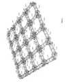
- FIG. 17is a perspective view of a grid of units in accordance with a second embodiment, shown here linked together in a 5 ⁇ 5 configuration but not interlocked;
- FIG. 18is a perspective view of a grid of units in accordance with a second embodiment, shown here linked together, and all units interlocked at 45 degrees, forming one possible shape determined in party by the preselected angles;
- FIG. 19is a top view of a single self-assembly unit in accordance with a third embodiment
- FIG. 20is a perspective view of a single self-assembly unit in accordance with a third embodiment
- FIG. 21is a side view of a single self-assembly unit in accordance with a third embodiment
- FIG. 22is a rear view of a single self-assembly unit in accordance with a third embodiment
- FIG. 23is a top view of a pair of the units of FIG. 19 , shown here linked together, but not interlocked;
- FIG. 24is a perspective view of a pair of the units of FIG. 19 , shown here linked together, but not interlocked;
- FIG. 25is a side view of a pair of the units of FIG. 19 , shown here linked together, but not interlocked;
- FIG. 26is a rear view of a pair of the units of FIG. 19 , shown here linked together, but not interlocked.
- FIG. 27is a top view of a pair of the units of FIG. 19 , shown here linked together and interlocked;
- FIG. 28is a perspective view of a pair of the units of FIG. 19 , shown here linked together and interlocked;
- FIG. 29is a side view of a pair of the units of FIG. 19 , shown here linked together and interlocked;
- FIG. 30is a rear view of a pair of the units of FIG. 19 , shown here linked together and interlocked;
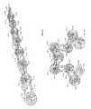
- FIG. 31is a perspective view of a chain of forty five units of FIG. 19 , shown here linked together, but not interlocked;
- FIG. 32is a perspective view of a chain of forty five units of FIG. 19 , shown here linked together and all units interlocked at custom angles, forming one possible shape, the modeling of the Crambin Protein strand, determined in part by the preselected angles that make up the Crambin Protein;
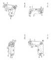
- FIG. 33is a top view of a single self-assembly unit in accordance with a fourth embodiment
- FIG. 34is a perspective view of a single self-assembly unit in accordance with a fourth embodiment
- FIG. 35is a side view of a single self-assembly unit in accordance with a fourth embodiment
- FIG. 36is a rear view of a single self-assembly unit in accordance with a fourth embodiment
- FIG. 37is a top view of a pair of the units of FIG. 33 , shown here linked together, but not interlocked;
- FIG. 38is a perspective view of a pair of the units of FIG. 33 , shown here linked together, but not interlocked;
- FIG. 39is a side view of a pair of the units of FIG. 33 , shown here linked together, but not interlocked;
- FIG. 40is a rear view of a pair of the units of FIG. 33 , shown here linked together, but not interlocked;
- FIG. 41is a top view of a pair of the units of FIG. 33 , shown here linked together and interlocked;
- FIG. 42is a perspective view of a pair of the units of FIG. 33 , shown here linked together and interlocked;
- FIG. 43is a side view of a pair of the units of FIG. 33 , shown here linked together and interlocked;
- FIG. 44is a rear view of a pair of the units of FIG. 33 , shown here linked together and interlocked;
- FIG. 45is a perspective view of a chain of twenty nine units of FIG. 33 , shown here linked together, but not interlocked;
- FIG. 46is a perspective view of a chain of twenty nine units of FIG. 33 , shown here linked together and all units interlocked at custom angles, forming one possible 2-dimensional shape, determined in party by the preselected angles that make up the letters “WOW”;
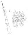
- FIG. 47is a perspective view of a chain of pre-linked units manufactured as a single chain, including assembly arms and hubs, shown here not interlocked;
- FIG. 48is a perspective view of a chain of pre-linked units of FIG. 47 , shown here interlocked at custom angles, forming one possible 3-dimensional shape, determined in party by the preselected angles that make up complex cube shape;
- linkmeans at least two connected units in a flexible state that is ready to accept an external energy source.
- interlockmeans the manipulation of two linked units, such that one of the units moves into a locked position at a preselected angle.
- the interlocking mechanismmay include physical latching, magnetic attraction, material expansion, cable tensioning etc.
- the sequential interlocking of linked unitscan achieve a global configuration determined by the face geometry and preselected angle of the hub
- chainmeans a series (more than two) linked units connected in a linear, 1-dimensional, sequence.
- gridmeans a series (more than two) linked units connected in a 2-dimensional pattern rather than a linear, 1-dimensional, pattern.
- the term “hub”means a main element of a self-assembly unit that has the function of specifying the transformational angle between two units given a suitable energy input.
- the hubmay contain components including but not limited to types such as: a connector, an interlocking latch, a stopping wall, a flexure arm, a pin, a pinhole, and an elastic hole.
- the hubmay contain a plurality of components of a given type, and similarly may exclude components of selected types.
- assembly armmeans a main element of a self-assembly unit that is coupled to the hub and defines a linear distance between the hub to which it is coupled and the hub of another unit to which it is linked.
- interlocking latchmeans a locking mechanism associated with the hub of a first self-assembly unit that mechanically traps an arm of a second self-assembly unit in the hub of the first self-assembly unit a specific angle and into a specific position.
- stopping wallmeans a structure in a hub of a first unit that establishes a limit of movement of a main element of a second unit that is linked to the first unit.
- a stopping wallmay be implemented, for example, so that stopping walls on two linked units come together to specific a chamfer angle for folding.
- a stopping wall of a first unitmay be configured to act as a back-stop when an assembly arm of a second unit rotates into an interlocking position.
- flexure armmeans a cantilevered structure in a hub of a first unit for receiving at least a portion of an assembly arm of a second unit in a manner that flexes in response to torque supplied by the assembly arm of the second unit.
- the flexure armapplies a force on the captured assembly arm that is greater when the arm is moved near the base of the cantilevered structure and smaller as the arm is move away from the base.
- pinmeans a component in a main element of a first self-assembly unit that fits into a pinhole or recess of the main element and allows a second self-assembly unit to rotate about an axis defined by the component.
- the term “recess”means an area in a main element of a self-assembly unit that receives a pin.
- pinholemeans an area in a main element of a first self-assembly unit that receives a pin and constrains the pin from moving except along the long axis of the pin.
- the pinholeenables the rotation of a second self-assembly unit about an axis defined by a pin inserted in the pinhole.
- elastic holemeans area passageway in one or more main elements of a self-assembly unit that receives a piece of elastic cord or other type of material to supply a suitable energy source to the self-assembly system.
- energy inputmeans unguided energy in the form of kinetic energy, including but not limited to vibration, shaking, heating, and sliding, or in the form of release of potential energy, including but not limited to that imparted by an elastic cord to a set of self-assembly units that are oriented in a manner as to cause stretching of the cord, or resulting from elevation over a surface onto which the system is dropped or thrown; or a mixture of any of the foregoing forms of energy; while many different forms of energy may be employed, it is principally required that the energy provide random forces on the system so that eventually orientations will result between adjacent units of the system wherein they will interlock with one another.
- the energyis “unguided” we mean to require that the energy source does not define the shape assumed by the self-assembly system when subjected to the energy; rather the self-assembly system itself defines the shape.
- Various embodiments of the present inventionprovide self-assembly units that can be used in the physical modeling of biological, chemical, computational, robotic, material forms of self-assembly and self-organizational processes, either naturally found or man-made.
- Embodiments hereinmay be constructed in size ranges including nano-scale, human-scale, and even astronomical-scale.
- Embodiments hereinmay be used to model protein folding and DNA origami where single sequences of assembly information, simple units with a desired state and an external force, can build any 3-dimensional functioning structure.
- This particular implementationuses a 3-dimensional printed plastic material with individual units that can be assembled piece-by-piece and shaken to fold into a 3-dimensional shape.
- This implementationlends itself towards a self-assembly toy that allows the user to simply print, buy or build a 1-dimensional or 2-dimensional shape then add an energy source and build a desired 3-dimensional structure, text, figure or functioning/transforming part.
- Embodiments hereinmay be utilized to build large-scale pavilions, tent structures or other quickly deployable architectural structures.
- Embodiments hereincan also serve as an educational device, a novelty device, a functional structural assembly system, a method for constructing large rigid enclosures, for making mechanical and transformable appendages, at extremely small scales to make structures at biological scales or surfaces that are programmable, deformable, adaptable or dynamic, or transformable space infrastructure systems.
- Embodiments hereindo not necessarily require electricity or motors (although such aspects can be incorporated in various embodiments, but rely on mechanical and geometric structures to provide the “state” of each unit.
- Various embodimentsmay be implemented in a wide range of scales to provide functional, low cost, low-energy, and precise rigid 3-dimensional structures from simple 1-dimensional or 2-dimensional patterns and an energy input.
- FIG. 1is a top view of a single self-assembly unit in accordance with an embodiment of the present invention.
- the unitincludes a pair of assembly arms 103 and hub 106 .
- FIG. 2is perspective view of the single self-assembly unit of FIG. 1 .
- the hub 106includes an arrangement by which an arm 103 of another unit can be linked and optionally interlocked 105 .
- FIG. 3is a side view of the single self-assembly unit of FIG. 1 .
- this viewit can be seen that there are two flexure arms 107 and two stopping walls 108 on opposite sides of the hub 106 .
- the flexure arms 107are cantilevered off of the hub as to provide less friction towards the interlocking latch 105 .
- FIG. 4is a rear view of the single self-assembly unit of FIG. 1 . In this view it can be seen that there is a pin 101 that can be received by the recess 102 that are situated at the end of the arms 103 .
- FIGS. 1-4This embodiment is constructed by adding individual, self-similar, units together to form a chain.
- Each unitcan be made of plastic, rubber, wood, metal or any other solid or semi-rigid material.
- the unitincludes a hub 106 and arms 103 .
- the arms 103include a pin 101 and a recess 102 to receive the pin.
- This particular pin 101has a diameter of +/ ⁇ 0.125′′ (in a specific implementation of the embodiment) and an equivalent diameter on the recess 102 .
- the pin 101 and recess 102come into contact with one another when they are squeezed together, where the pivoting movement is coming from the connecting arms 103 .
- the armsmay be implemented, for example, with an approximate dimension of 0.125′′ ⁇ 0.125′′.
- the armsare directly connected to the pin/recess 101 & 102 and the hub portion 106 of the unit.
- the armsprovide slight flexibility from their connection to the hub 106 due to the cantilever and material property. This flexibility allows the pin 101 and recess 102 to touch.
- the hub portion of the unitincludes the flexure arms 107 , the interlocking latch 105 , the pinhole 104 , and the stopping walls 108 .
- the hub 106provides the firm connection to the arms 103 and the pin/recess 101 & 102 .
- the hubhas an approximate sphere dimension of 0.6′′.
- the hub 106then links to the two flexure arms 107 that are cantilevered outwards.
- the flexure arms 107have an approximate dimension of 0.125′′ ⁇ 0.063′′.
- the cantilever flexure arms 107provide more friction when a second unit is linked and rotated towards the hub 106 and less friction when rotated away from the connection, towards the interlocking latch 105 .
- the interlocking latches 105have an approximate dimension of 0.133′′ ⁇ 0.158′′, which is just enough to house each of the arms 103 of a second unit when they have rotated to the end of the flexure arms 107 . Once the second unit's arms have reached the end of the flexure arm 107 the unit will pop into the interlocking latch 105 and be locked into position.
- the stopping walls 108are adjacent to the interlocking latches 105 and stop a second unit's arms 103 from rotating further.
- the final feature of the hub portion of the unitis the pinhole 104 .
- the pinhole 104is a hole that receives the pin 101 of a second unit when it has been linked. This provides the pivot of rotation for the second unit as it swivels underneath the flexure arms 107 and snaps into the interlocking latches 105 .
- a userwill expand the arms 103 of a single unit far enough to slip the pin 101 and recess 102 over the flexure arms 107 and hub 106 of a second unit.
- the first unit's pin 101will fall into place directly into the pinhole 104 of the second unit.
- the flexure arms 107 of the second unitshould be lifted and separated slightly as to allow the arms 103 of the first unit to slide underneath of them.
- both unitsare in a linked state and ready for energy to transform them into an interlocked state or to be linked to further units.
- the usercan decide how many units to link together and at which end of the chain to build from.
- An alternate method for constructing a self-assembly systemis to print (using a three-dimensional printer), mold, cast or manufacture an entire chain as a single functioning piece. Such a method would then obviate the need for manually linking of the individual units.
- FIG. 5is a top view of a pair of the units of FIG. 1 , shown here linked together, but not interlocked.
- the linked stateincludes a second unit rotated 90 degrees about the long axis in order to situate the pin 101 into the pinhole 104 of the hub 106 of the first unit.
- the second unit's arms 103reside underneath the flexure arms 107 and are providing friction as the second unit rotates.
- the second unitis free to rotate about the pivot point at the center of the pinhole 104 , underneath the flexure arms 107 .
- FIG. 6is a perspective view of a pair of the units as shown in FIG. 5 .
- FIG. 7is a side view of a pair of the units as shown in FIG. 5 .
- the arms 103 of the second unitare compressed slightly to fall below the flexure arms 107 of the first unit, providing friction and resistance as the second unit rotates freely about the pivot point at the center of the pinhole 104 .
- FIG. 8is a rear view of a pair of the units as shown in FIG. 5 .
- the usermay choose which orientation to place the unit.
- the flexure arms 107provide a single direction of less resistance (towards the interlocking latch 105 ). This means that the user can choose to orient the unit in one of two ways (with the interlocking latch 105 upwards or the interlocking latch 105 downwards (possibly left or right depending on the orientation in 3-dimensions)).
- the userlinks a unit to the end of the chain in a specified orientation, it will explicitly determine the ultimate rotation of that unit (towards the least resistance of the flexure arms 107 ).
- the selected orientation of the units and the preselected angle of the interlocking latchwill determine, in part, the final 3-dimensional shape of the interlocked chain.
- FIG. 9is a top view of a pair of the units of FIG. 1 , shown here linked together, and interlocked at 90 degrees.
- FIG. 10is a perspective view of a pair of the units as shown in FIG. 9 . It can be seen in this view that the second unit's arms 103 have expanded outwards after being compressed under the flexure arms 107 of the first unit and finally reaching the interlocking latch 105 of the first unit.
- FIG. 11is a side view of a pair of the units as shown in FIG. 9 .
- FIG. 12is a rear view of a pair of the units as shown in FIG. 9 .
- the linked and interlocked stateincludes a pair of units where the second unit is rotated and the arms 103 are locked into the interlocking latch 105 of the hub 106 of the first unit.
- the second unithas rotated from FIG. 5 towards the interlocking latch 105 and has been interlocked at 90 degrees. It can be seen that the dimension of the interlocking latch 105 of the first unit is just wide enough to receive the width of the arms 103 of the second unit to hold it into place.
- FIG. 13is a perspective view of a chain of eight units of FIG. 1 , shown here linked together, but not interlocked. It can be seen here that a chain of units is linked together with compressed arms 103 underneath the flexure arms 107 of the previous units.
- the alternating rotated pattern of the unitsspecifies the folding direction (left, right, up, down) whereas the interlocking latch 105 angle specifies the angle to witch they will interlock. Both the angle and the orientation dictate, in part, the 3-dimensional shape.
- FIG. 14is a perspective view of a chain of eight units of FIG. 1 , shown here linked together, and all units interlocked at 90 degrees, forming one possible shape determined in party by the preselected angles.
- FIG. 15is a perspective view of a chain of eight units of FIG. 1 , shown here linked together, but not interlocked.
- FIG. 16is a perspective view of a chain of eight units of FIG. 1 , shown here linked together, and interlocked at 90 degrees, forming a second possible shape determined in party by the preselected angles. It can be seen in this view that the second 3-dimensional shape is significantly different than the shape in FIG. 14 , demonstrating the different interlocking latch 105 angles and the selected orientations when they are linked.
- FIGS. 13-16When the user has finished linking the desired number of units in the desired orientation for each unit, the chain is ready to be activated (“Linked State”). The user simply picks up the chain from either end (or any part of the chain) and begins to randomly shake it (or add another type of energy). The random shaking provides the direct force on each of the units such that they will each travel in the path of least resistance underneath the flexure arms 107 and will automatically snap into the angle of the interlocking latch 105 . Within a few seconds (depending on the length of the chain, complexity of the fold sequence and the amount of energy supplied) all of the units will have interlocked into the correct position and the global 3-dimensional shape will have been assembled.
- the desired 3-dimensional shapecan be any arbitrary 1-dimensional, 2-dimensional or 3-dimensional shape of any arbitrary length and the user can simply shake the initially flexible chain to fully self-assemble the desired shape.
- Potential shapesmay include (although there are limitless possible configurations): a cube, spiral, sphere or other arbitrary polyhedron and arbitrary surfaces etc.
- the two 3-dimensional configurations showninclude a 3-dimensional cantilevered structure (A- 04 FIG. 14 ) and a spiral or zigzag 3-dimensional structure (A- 05 FIG. 16 ).
- FIG. 17is a perspective view of a grid of units in accordance with a second embodiment, shown here linked together in a 5 ⁇ 5 configuration but not interlocked. It can be seen in this view that each of the arms 103 are compressed slightly to fall underneath of the flexure arms 107 and are in a linked and flexible state, ready for activation energy.
- FIG. 18is a perspective view of a grid of units in accordance with a second embodiment, shown here linked together, and all units interlocked at 45 degrees, forming one possible shape determined in party by the preselected angles. It can be seen that each of the self-assembly units' arms 103 have locked into the interlocking latch 105 of the neighboring unit. It can also be seen that the combination of the preselected angles and orientation have in part determined the rigid 3-dimensional structure of the final shape.
- FIGS. 17-18A secondary embodiment has been shown in the form of a 2-dimensional grid of units. These units contain the same mechanical elements as the previous chain embodiment; however, they now have up to four directions of connection.
- the initial state of the unit configurationis a flat 2-dimensional grid (“Linked State”); this indicates that the units are ready to be activated. The user simply picks up the grid of units and begins to randomly shake it. The random shaking provides the direct force on each of the units such that they will each travel in the path of least resistance underneath the flexure arms 107 and will automatically snap into the correct interlocking latch 105 .
- the desired global configurationcan be any arbitrary 3-dimensional shape that can be made with a 2-dimensional topology (a surface based topology). This desired 3-dimensional shape is described by the series of interlocked angles that are applied to the corresponding unit's interlocking latch 105 —this grid of angles will ensure that random shaking correctly assembles the desired 3-dimensional shape.
- Potential shapesmay include (although there are limitless possible configurations): a bowl, saddle, hyperbolic parabaloid, sphere or other arbitrary surface.
- the 3-dimensional configuration shownis a saddle surface. (We have also demonstrated that the 2-dimensional grid system can be folded into a 3-dimensional structure with alternate forms of energy input, including; random shaking, magnetic and elastics to name a few.)
- FIG. 19is a top view of a single self-assembly unit in accordance with a third embodiment.
- the unitincludes a single assembly arm 103 and pair of hubs 106 at either end of the unit.
- FIG. 20is a perspective view of a single self-assembly unit in accordance with a third embodiment.
- the hubs 106include a pinhole 104 and stopping wall 108 .
- An elastic hole 109connects the center of the two stopping walls 108 on either end of the unit.
- FIG. 21is a side view of a single self-assembly unit in accordance with a third embodiment.
- FIG. 22is a rear view of a single self-assembly unit in accordance with a third embodiment.
- each unitis unique compared with every other unit in the chain—with two unique angles of stopping walls 108 at the hub 106 at either end of the unit.
- the stopping walls 108each have unique angles in accordance to the final global shape of the self-assembly system.
- the stopping walls 108will correspond to the stopping wall 108 on the next unit to form the specific folding angle.
- the unitincludes a pair of hubs 106 and a connecting arm 103 .
- the arm 103is directly connected to the two hubs 106 , adding linear length to the unit.
- An elastic hole 109connects both stopping walls 108 on either end of the unit, to receive an elastic cord during linking of the chain.
- One of the hubs 106can be considered a female shape while the other hub 106 can be considered the male shape and will receive the female shape of the next unit.
- the pinhole 104will receive a pin that is inserted during the linking of units to form a chain. The pin will provide rotational movement of unit about the other unit.
- FIG. 23is a top view of a pair of the units of FIG. 19 , shown here linked together, but not interlocked.
- the linked stateincludes a second unit rotated about the long axis to a specific angle, pertaining to the global 3-dimensional structure of the chain.
- the female assembly hub 106 of the first unitlinks with the male assembly hub 106 of the second unit in order to align the pinhole 104 of the first unit with the pinhole 104 of the second unit.
- the second unitis free to rotate about the axis through the hub 106 at the center of the pinhole 104 .
- FIG. 24is a perspective view of a pair of the units of FIG. 19 , shown here linked together, but not interlocked.
- FIG. 25is a side view of a pair of the units of FIG. 19 , shown here linked together, but not interlocked. It can be seen that the stopping wall 108 of the first unit and stopping wall 108 of the second unit are facing each other and form an unique angle that allows the second unit to rotate about the pinhole 104 axis and ensure that the two stopping walls 108 meet one another face-to-face.
- FIG. 26is a rear view of a pair of the units of FIG. 19 , shown here linked together, but not interlocked.
- FIGS. 23-26When the user links a unit to the end of the chain, the two unit's unique stopping wall 108 angles will explicitly determine the ultimate rotation of that unit (until the second unit's stopping wall 108 meets the first unit's stopping wall 108 ). The unique angle of the hub about the long axis and the preselected angle of the stopping walls 108 will determine, in part, the final 3-dimensional shape of the interlocked chain.
- FIG. 27is a top view of a pair of the units of FIG. 19 , shown here linked together and interlocked.
- FIG. 28is a perspective view of a pair of the units of FIG. 19 , shown here linked together and interlocked. It can be seen in this view that the second unit has rotated about the hub 106 at the center point of the pinhole 104 and that the stopping wall 108 of the second unit has met the stopping wall 108 of the first unit, face-to-face, completing the unique angle for this pair of units.
- FIG. 29is a side view of a pair of the units of FIG. 19 , shown here linked together and interlocked.
- FIG. 30is a rear view of a pair of the units of FIG. 19 , shown here linked together and interlocked.
- the linked and interlocked stateincludes a pair of units where the second unit is rotated such that the stopping walls 108 of both units meet one another.
- the rotationin this particular embodiment, is due to the compression force of an elastic cord that has been threaded through the linked units, through the elastic hole 109 shown connecting the two stopping wall 108 faces of each unit.
- FIG. 31is a perspective view of a chain of forty-five units of FIG. 19 , shown here linked together, but not interlocked.
- FIG. 32is a perspective view of a chain of forty-five units of FIG. 19 , shown here linked together and all units interlocked at custom angles, forming one possible shape, the modeling of the Crambin Protein strand, determined in party by the preselected angles that make up the Crambin Protein.
- FIGS. 31-32When the user has finished linking the desired number of units, the chain is ready to be activated (“Linked State”). The user threads through the elastic holes 109 of each unit an elastic cord of the appropriate compression force and diameter. Then the elastic cord is pulled tight and the user ties the ends of the cord at the ends of the linked chain. The user simply picks up the chain from both ends and stretches it out completely straight and releases it, or throws the unit into the air (or any other technique for releasing the compression force onto the chain). The elastic cord provides a compressive force upon each unit such that the units rotate about the hub 106 at the center point of the pinhole 104 ensuring that the stopping walls 108 have been rotated to meet one other at the specified angle.
- the desired 3-dimensional shapecan be any arbitrary 1-dimensional, 2-dimensional or 3-dimensional shape of any arbitrary length.
- the chainis shown to have forty-five units linked together and when self-assembled the interlocked 3-dimensional structure, modeling the 3-dimensional structure of the Crambin Protein strand.
- FIG. 33is a top view of a single self-assembly unit in accordance with a fourth embodiment.
- the unitincludes a single assembly arm 103 and pair of hubs 106 at either end of the unit.
- FIG. 34is a perspective view of a single self-assembly unit in accordance with a fourth embodiment.
- the male hubincludes a pin 101 , a magnet 105 at a pre-selected angle and a stopping wall 108 .
- the female hubincludes two pinholes 104 and a stopping wall. It can also be seen that there is a magnet 105 positioned at the top of the arm 103 in between the two hubs 106 .
- FIG. 35is a side view of a single self-assembly unit in accordance with a fourth embodiment.
- FIG. 36is a rear view of a single self-assembly unit in accordance with a fourth embodiment.
- FIGS. 33-36This embodiment is constructed by adding individual, self-similar, units together to form a linked chain.
- Each unitcan be made of plastic, rubber, wood, metal or any other solid or semi-rigid material.
- each unitis self-similar but becomes unique when a magnet 105 is placed into one of the possible angles of the magnet holes 105 in the hub.
- the unitincludes a pair of hubs 106 and a connecting arm 103 .
- the arm 103is directly connected to the two hubs 106 , adding linear length to the unit.
- One of the hubs 106can be considered a female shape while the other hub 106 can be considered the male shape and will receive the female shape of the next unit when linked.
- the pinholes 104 of a first unitwill receive the pin 101 of a next unit when linked.
- the pin 101will provide rotational movement of unit about the other unit.
- FIG. 37is a top view of a pair of the units of FIG. 33 , shown here linked together, but not interlocked.
- the linked stateincludes a second unit that is connected about the female hub 106 to a first unit about the male hub 106 .
- the two hubs 106can be seen as co-planar to one another and thus the two units, when connected and rotated about the pin 101 , will rotate in a 2-dimensional plane.
- the second unitis free to rotate about the axis through the hub 106 at the center of the pin 101 .
- the magnet 105 in the male hub 106 of the first unitdoes not align vertically with the magnet 105 in the arm 103 of the second unit.
- FIG. 38is a perspective view of a pair of the units of FIG. 33 , shown here linked together, but not interlocked.
- FIG. 39is a side view of a pair of the units of FIG. 33 , shown here linked together, but not interlocked.
- FIG. 40is a rear view of a pair of the units of FIG. 33 , shown here linked together, but not interlocked.
- the magnet 105 position in the hub 106 of the first unitwill specifically dictate the angle of rotation of the second unit such that the magnet 105 in the arm 103 of the second unit will align.
- the unique position of the magnet 105 of the first unitwill determine, in part, the final 3-dimensional shape of the interlocked chain.
- the usercan also decide the orientation of the second unit to be aligned so that the magnet 105 in the arm 103 of the second unit is facing upwards or is facing downwards, 180 degrees along the long axis of the arm 103 . This will in effect flip the fold angle 180 degrees.
- FIG. 41is a top view of a pair of the units of FIG. 33 , shown here linked together and interlocked. It can be seen in this view that the second unit has rotated about the hub 106 at the center point of the pin 101 and that magnet 105 of the first unit and the magnet 105 of the second unit have aligned, completing the rotational angle of the unit pair. It can also be seen that the rotation of the second unit is in place with the first unit because of the co-planar orientation of the two hubs 106 of both units.
- FIG. 42is a perspective view of a pair of the units of FIG. 33 , shown here linked together and interlocked.
- FIG. 43is a side view of a pair of the units of FIG. 33 , shown here linked together and interlocked.
- FIG. 44is a rear view of a pair of the units of FIG. 33 , shown here linked together and interlocked.
- the linked and interlocked stateincludes a pair of units where the second unit is rotated such that the magnet 105 of the first unit and the magnet 105 of the second unit align with each other vertically.
- the rotationin this particular embodiment, is due to magnetic force of attraction between the two magnets 105 and causes the second unit to rotate about the pin 101 of the first unit.
- the rotated anglecan be changed in each unit by moving the magnet 105 into a different position in the hub 106 .
- Each unitcan be configured to have a unique fold angle (magnet 105 position) or can have the same magnet 105 position and fold angle.
- FIG. 45is a perspective view of a chain of twenty-nine units of FIG. 33 , shown here linked together, but not interlocked.
- FIG. 46is a perspective view of a chain of twenty-nine units of FIG. 33 , shown here linked together and all units interlocked at custom angles, forming one possible shape, the letters “WOW” configured in a 2-dimensional plane.
- the linked statemust also include two magnets 105 positioned in each of the units.
- the usermust place a magnet 105 into the desired position of the hub 106 and a magnet 105 in the arm 103 of each unit.
- Thenassemble the linked units into a chain.
- the usersimply picks up the chain from both ends and stretches it out completely straight and releases it.
- the magnetic force of attraction from each magnet 105 in the hub 106 and the corresponding magnet 105 in the arm 103 of the next unitprovide a rotational force to fold each unit into the desired angle.
- the desired shapecan be any arbitrary 1-dimensional, 2-dimensional or 3-dimensional shape of any arbitrary length.
- the chainis shown to spell the letters “WOW” with twenty-nine units configured in a 2-dimensional plane.
- FIG. 47is a perspective view of a chain of pre-linked units manufactured as a single chain, including assembly arms and hubs, shown here not interlocked. It can be seen in this view that there is a series of assembly arms 103 connected to a series of hubs 106 manufactured directly into the chain.
- the hub 106 in this specific embodimentis a chamfered area that forms a fold angle for the chain when energy is supplied.
- FIG. 48is a perspective view of a chain of pre-linked units of FIG. 47 , shown here interlocked at custom angles, forming one possible 3-dimensional shape, determined in party by the preselected angles that make up complex cube shape.
- the chainhas been manufactured, in this specific embodiment, as a single chain (either printed, cast or any other technique that can produce a 1-dimensional or 2-dimensional pattern) including a series of hubs 106 and arms 103 (“Linked State”).
- the hubs 106are made of a specific material that will expand 100% when subject to water.
- wateris applied to the length of the chain by either dipping the chain into water or pouring water onto the chain. When water touches the hubs 106 , the material expands and forces the two faces of the hub 106 to come into contact with one another.
- the desired shapecan be any arbitrary 1-dimensional, 2-dimensional or 3-dimensional shape of any arbitrary length.
- the chainis shown to form the 3-dimensional structure of a complex cube shape. (Other embodiments have been tested that also were manufactured as a single chain with a material that becomes flexible when heated. If torsion springs or magnets are implemented into the hub and the chain is heated, the chain will fold into the desired 2-dimensional or 3-dimensional shape. When the heat is removed the material will harden and the global shape will remain. Many other embodiments of a 1-dimensional or 2-dimensional system with a single manufactured piece of material that responds to a supplied energy source, can be implemented that will self-assembly into an arbitrary 2-dimensional or 3-dimensional shape).
Landscapes
- Engineering & Computer Science (AREA)
- Physics & Mathematics (AREA)
- General Physics & Mathematics (AREA)
- Theoretical Computer Science (AREA)
- Educational Administration (AREA)
- Educational Technology (AREA)
- Business, Economics & Management (AREA)
- General Engineering & Computer Science (AREA)
- Algebra (AREA)
- Multimedia (AREA)
- Mechanical Engineering (AREA)
- Computational Mathematics (AREA)
- Mathematical Analysis (AREA)
- Mathematical Optimization (AREA)
- Mathematical Physics (AREA)
- Pure & Applied Mathematics (AREA)
- Toys (AREA)
Abstract
Description
The present application claims the benefit of, and priority from, U.S. provisional application Ser. No. 61/529,891, filed Aug. 31, 2011, and that application is hereby incorporated herein by reference.
The present invention relates generally to self-assembly systems and, more particularly, to self-assembly systems that are linked or linkable and that interlock at a set of preselected angles.
The various self-assembly or reconfigurable chains are disclosed in the following documents; [Arthur Olson US 20100168439 AI, Self-Assembled Polyhedra], [Douglas A. Engel U.S. Pat. No. 4,735,418, Puzzle Amusement Device], [Richard E. Schaedel U.S. Pat. No. 6,264,199 B1, Folding Puzzle/Transformational Toy with 24 Linked Tetrahedral Elements], [David H. Gracias U.S. Pat. No. 7,007,370 B2, Self-Assembled Electrical Networks], [Mark H. Yim US 2002/0043950 A1, High Mechanical Advantage Ratcheting Apparatus], [Bradford Tyler Sorensen US 2008/0066393 A1, Instant, Pre-Tensioned, Tool-Free, Polyhedral, Enclosure Construction System].
A set of self-assembly units that comprise at least one connector hub with a rotational axis and at least one assembly arm coupled to the hub that defines the assembly arm plane in which there is a longitudinal axis of the assembly arm. The set of self-assembly units may alternatively be manufactured as a single strand with many hubs and assembly arms directly linked together rather than assembled as individual elements. The connector hub and assembly arm are configured one after another so that (i) when the assembly arm of the first unit is linked with the connector hub of the second unit, a resulting linkage allows motion of the assembly arm of the first unit about the axis of the connector hub of the second unit and (ii) when the assembly arm is moved into a selected angle about the connector hub axis of the second unit, the assembly arm will interlock at the selected angle, the selected angle being selected from a set of defined angles. When the set of units are linked into a chain without interlocking and thereafter subjected to a suitable energy input, the set of units will interlock with one another so as to assume a shape determined at least in part by the set of defined angles.
In a related embodiment, the set is manufactured so that the units are intrinsically linked. Alternatively, each unit is separately manufactured and the units are configured to be linked after manufacturing of the units.
In another related embodiment, the set of defined angles includes only a single angle and therefore each unit of the set interlocks with any other unit of the set at the single angle.
Alternatively or in addition, the connector hub and assembly arm are configured so that the assembly arm of the first unit will interlock at the selected angle with the connector hub of the second unit in either a first orientation of the assembly arm of the first unit or a second orientation wherein the assembly arm of the first unit has been rotated about the longitudinal axis 180 degrees compared to the first orientation.
In a further related embodiment, the set includes at least two self-assembly units wherein the connector hub axis is not co-planar with the assembly arm plane, so that when the set of units are linked and interlocked, they define a 3-dimensional shape, such shape defined in part by the set of angles, in self-assembly units of the set, between the connector hub axis and the assembly plane. Optionally, the set includes at least two self-assembly units wherein the connector hub axis is perpendicular to the assembly arm plane, so that when the set of units are linked and interlocked, they define a 3-dimensional shape.
In another related embodiment, the set includes at least two self-assembly units wherein the connector hub axis is co-planar with the assembly arm plane, so that when the set of units are linked into a chain and interlocked, they assume a 2-dimensional shape.
In another related embodiment, the group of all preselected angles includes as many angles as there are units in the set and wherein each unit of the set interlocks with any other unit in the set at an angle that is distinct among the set of units.
Alternatively, the group of all preselected angles includes a smaller number of angles than there are units in the set, so that some angles are repeated when the set of units are interlocked with one another.
In a further related embodiment, each unit comprises a plurality of hubs.
In yet another related embodiment, each unit comprises a plurality of arms.
The foregoing features of embodiments will be more readily understood by reference to the following detailed description, taken with reference to the accompanying drawings, in which:
As used in this description and the accompanying claims, the following terms shall have the meanings indicated, unless the context otherwise requires:
The term “link” means at least two connected units in a flexible state that is ready to accept an external energy source.
The term “interlock” means the manipulation of two linked units, such that one of the units moves into a locked position at a preselected angle. The interlocking mechanism may include physical latching, magnetic attraction, material expansion, cable tensioning etc. The sequential interlocking of linked units can achieve a global configuration determined by the face geometry and preselected angle of the hub
The term “chain” means a series (more than two) linked units connected in a linear, 1-dimensional, sequence.
The term “grid” means a series (more than two) linked units connected in a 2-dimensional pattern rather than a linear, 1-dimensional, pattern.
The term “hub” means a main element of a self-assembly unit that has the function of specifying the transformational angle between two units given a suitable energy input. In carrying out this function, the hub may contain components including but not limited to types such as: a connector, an interlocking latch, a stopping wall, a flexure arm, a pin, a pinhole, and an elastic hole. In various embodiments, the hub may contain a plurality of components of a given type, and similarly may exclude components of selected types.
The term “assembly arm” means a main element of a self-assembly unit that is coupled to the hub and defines a linear distance between the hub to which it is coupled and the hub of another unit to which it is linked. The term “interlocking latch” means a locking mechanism associated with the hub of a first self-assembly unit that mechanically traps an arm of a second self-assembly unit in the hub of the first self-assembly unit a specific angle and into a specific position.
The term “stopping wall” means a structure in a hub of a first unit that establishes a limit of movement of a main element of a second unit that is linked to the first unit. A stopping wall may be implemented, for example, so that stopping walls on two linked units come together to specific a chamfer angle for folding. Alternatively, for example, a stopping wall of a first unit may be configured to act as a back-stop when an assembly arm of a second unit rotates into an interlocking position.
The term “flexure arm” means a cantilevered structure in a hub of a first unit for receiving at least a portion of an assembly arm of a second unit in a manner that flexes in response to torque supplied by the assembly arm of the second unit. The flexure arm applies a force on the captured assembly arm that is greater when the arm is moved near the base of the cantilevered structure and smaller as the arm is move away from the base.
The term “pin,” means a component in a main element of a first self-assembly unit that fits into a pinhole or recess of the main element and allows a second self-assembly unit to rotate about an axis defined by the component.
The term “recess” means an area in a main element of a self-assembly unit that receives a pin.
The term “pinhole” means an area in a main element of a first self-assembly unit that receives a pin and constrains the pin from moving except along the long axis of the pin. The pinhole enables the rotation of a second self-assembly unit about an axis defined by a pin inserted in the pinhole.
The term “elastic hole” means area passageway in one or more main elements of a self-assembly unit that receives a piece of elastic cord or other type of material to supply a suitable energy source to the self-assembly system.
The term “energy input”, applied to a self-assembly system in accordance with an embodiment of the present invention, means unguided energy in the form of kinetic energy, including but not limited to vibration, shaking, heating, and sliding, or in the form of release of potential energy, including but not limited to that imparted by an elastic cord to a set of self-assembly units that are oriented in a manner as to cause stretching of the cord, or resulting from elevation over a surface onto which the system is dropped or thrown; or a mixture of any of the foregoing forms of energy; while many different forms of energy may be employed, it is principally required that the energy provide random forces on the system so that eventually orientations will result between adjacent units of the system wherein they will interlock with one another. When we said that the energy is “unguided” we mean to require that the energy source does not define the shape assumed by the self-assembly system when subjected to the energy; rather the self-assembly system itself defines the shape.
Various embodiments of the present invention provide self-assembly units that can be used in the physical modeling of biological, chemical, computational, robotic, material forms of self-assembly and self-organizational processes, either naturally found or man-made. Embodiments herein may be constructed in size ranges including nano-scale, human-scale, and even astronomical-scale.
Embodiments herein may be used to model protein folding and DNA origami where single sequences of assembly information, simple units with a desired state and an external force, can build any 3-dimensional functioning structure. This particular implementation uses a 3-dimensional printed plastic material with individual units that can be assembled piece-by-piece and shaken to fold into a 3-dimensional shape. This implementation lends itself towards a self-assembly toy that allows the user to simply print, buy or build a 1-dimensional or 2-dimensional shape then add an energy source and build a desired 3-dimensional structure, text, figure or functioning/transforming part. Embodiments herein may be utilized to build large-scale pavilions, tent structures or other quickly deployable architectural structures. Embodiments herein can also serve as an educational device, a novelty device, a functional structural assembly system, a method for constructing large rigid enclosures, for making mechanical and transformable appendages, at extremely small scales to make structures at biological scales or surfaces that are programmable, deformable, adaptable or dynamic, or transformable space infrastructure systems. Embodiments herein do not necessarily require electricity or motors (although such aspects can be incorporated in various embodiments, but rely on mechanical and geometric structures to provide the “state” of each unit. Various embodiments may be implemented in a wide range of scales to provide functional, low cost, low-energy, and precise rigid 3-dimensional structures from simple 1-dimensional or 2-dimensional patterns and an energy input.
We now discussFIGS. 1-4 in specificity. This embodiment is constructed by adding individual, self-similar, units together to form a chain. Each unit can be made of plastic, rubber, wood, metal or any other solid or semi-rigid material. In this particular embodiment of the self-assembly system, there is only one unit type—each unit is identical to every other unit in the chain. The unit includes ahub 106 andarms 103. Thearms 103 include apin 101 and arecess 102 to receive the pin. Thisparticular pin 101 has a diameter of +/−0.125″ (in a specific implementation of the embodiment) and an equivalent diameter on therecess 102. Thepin 101 andrecess 102 come into contact with one another when they are squeezed together, where the pivoting movement is coming from the connectingarms 103. The arms may be implemented, for example, with an approximate dimension of 0.125″×0.125″. The arms are directly connected to the pin/recess 101 &102 and thehub portion 106 of the unit. The arms provide slight flexibility from their connection to thehub 106 due to the cantilever and material property. This flexibility allows thepin 101 andrecess 102 to touch.
The hub portion of the unit includes theflexure arms 107, the interlockinglatch 105, thepinhole 104, and the stoppingwalls 108. Thehub 106 provides the firm connection to thearms 103 and the pin/recess 101 &102. In a specific implementation, the hub has an approximate sphere dimension of 0.6″. Thehub 106 then links to the twoflexure arms 107 that are cantilevered outwards. Theflexure arms 107 have an approximate dimension of 0.125″×0.063″. The cantilever flexurearms 107 provide more friction when a second unit is linked and rotated towards thehub 106 and less friction when rotated away from the connection, towards the interlockinglatch 105. These flexure arms help to guide the rotation of a second unit towards the interlockinglatch 105. The interlocking latches105 have an approximate dimension of 0.133″×0.158″, which is just enough to house each of thearms 103 of a second unit when they have rotated to the end of theflexure arms 107. Once the second unit's arms have reached the end of theflexure arm 107 the unit will pop into the interlockinglatch 105 and be locked into position. The stoppingwalls 108 are adjacent to the interlocking latches105 and stop a second unit'sarms 103 from rotating further. The final feature of the hub portion of the unit is thepinhole 104. Thepinhole 104 is a hole that receives thepin 101 of a second unit when it has been linked. This provides the pivot of rotation for the second unit as it swivels underneath theflexure arms 107 and snaps into the interlocking latches105.
To link two units together in this implementation of the self-assembly system, a user will expand thearms 103 of a single unit far enough to slip thepin 101 andrecess 102 over theflexure arms 107 andhub 106 of a second unit. The first unit'spin 101 will fall into place directly into thepinhole 104 of the second unit. Theflexure arms 107 of the second unit should be lifted and separated slightly as to allow thearms 103 of the first unit to slide underneath of them. Once thearms 103 of the first unit are beneath theflexure arms 107 of the second unit, both units are in a linked state and ready for energy to transform them into an interlocked state or to be linked to further units. The user can decide how many units to link together and at which end of the chain to build from.
An alternate method for constructing a self-assembly system is to print (using a three-dimensional printer), mold, cast or manufacture an entire chain as a single functioning piece. Such a method would then obviate the need for manually linking of the individual units.
We now discuss the embodiment ofFIGS. 5-8 . When the user links each unit of this embodiment to the end of the chain, the user may choose which orientation to place the unit. As previously described, theflexure arms 107 provide a single direction of less resistance (towards the interlocking latch105). This means that the user can choose to orient the unit in one of two ways (with the interlockinglatch 105 upwards or the interlockinglatch 105 downwards (possibly left or right depending on the orientation in 3-dimensions)). When the user links a unit to the end of the chain in a specified orientation, it will explicitly determine the ultimate rotation of that unit (towards the least resistance of the flexure arms107). The selected orientation of the units and the preselected angle of the interlocking latch will determine, in part, the final 3-dimensional shape of the interlocked chain.
We now discuss the embodiment ofFIGS. 9-12 . It can be seen that the linked and interlocked state includes a pair of units where the second unit is rotated and thearms 103 are locked into the interlockinglatch 105 of thehub 106 of the first unit. The second unit has rotated fromFIG. 5 towards the interlockinglatch 105 and has been interlocked at 90 degrees. It can be seen that the dimension of the interlockinglatch 105 of the first unit is just wide enough to receive the width of thearms 103 of the second unit to hold it into place.
We now discuss the embodiment ofFIGS. 13-16 . When the user has finished linking the desired number of units in the desired orientation for each unit, the chain is ready to be activated (“Linked State”). The user simply picks up the chain from either end (or any part of the chain) and begins to randomly shake it (or add another type of energy). The random shaking provides the direct force on each of the units such that they will each travel in the path of least resistance underneath theflexure arms 107 and will automatically snap into the angle of the interlockinglatch 105. Within a few seconds (depending on the length of the chain, complexity of the fold sequence and the amount of energy supplied) all of the units will have interlocked into the correct position and the global 3-dimensional shape will have been assembled. The desired 3-dimensional shape can be any arbitrary 1-dimensional, 2-dimensional or 3-dimensional shape of any arbitrary length and the user can simply shake the initially flexible chain to fully self-assemble the desired shape. Potential shapes may include (although there are limitless possible configurations): a cube, spiral, sphere or other arbitrary polyhedron and arbitrary surfaces etc. The two 3-dimensional configurations shown include a 3-dimensional cantilevered structure (A-04FIG. 14 ) and a spiral or zigzag 3-dimensional structure (A-05FIG. 16 ).
We now discuss the embodiment ofFIGS. 17-18 . A secondary embodiment has been shown in the form of a 2-dimensional grid of units. These units contain the same mechanical elements as the previous chain embodiment; however, they now have up to four directions of connection. The initial state of the unit configuration is a flat 2-dimensional grid (“Linked State”); this indicates that the units are ready to be activated. The user simply picks up the grid of units and begins to randomly shake it. The random shaking provides the direct force on each of the units such that they will each travel in the path of least resistance underneath theflexure arms 107 and will automatically snap into thecorrect interlocking latch 105.
Within a few seconds all of the units will have interlocked into the correct position and the global 3-dimensional structure will have been assembled. The desired global configuration can be any arbitrary 3-dimensional shape that can be made with a 2-dimensional topology (a surface based topology). This desired 3-dimensional shape is described by the series of interlocked angles that are applied to the corresponding unit's interlockinglatch 105—this grid of angles will ensure that random shaking correctly assembles the desired 3-dimensional shape. Potential shapes may include (although there are limitless possible configurations): a bowl, saddle, hyperbolic parabaloid, sphere or other arbitrary surface. The 3-dimensional configuration shown is a saddle surface. (We have also demonstrated that the 2-dimensional grid system can be folded into a 3-dimensional structure with alternate forms of energy input, including; random shaking, magnetic and elastics to name a few.)
We now discussFIGS. 19-22 in specificity. This embodiment is constructed by adding individual units together to form a linked chain. Each unit can be made of plastic, rubber, wood, metal or any other solid or semi-rigid material. In this particular embodiment of the self-assembly system, each unit is unique compared with every other unit in the chain—with two unique angles of stoppingwalls 108 at thehub 106 at either end of the unit. The stoppingwalls 108, each have unique angles in accordance to the final global shape of the self-assembly system. The stoppingwalls 108 will correspond to the stoppingwall 108 on the next unit to form the specific folding angle. The unit includes a pair ofhubs 106 and a connectingarm 103. Thearm 103 is directly connected to the twohubs 106, adding linear length to the unit. Anelastic hole 109 connects both stoppingwalls 108 on either end of the unit, to receive an elastic cord during linking of the chain. One of thehubs 106 can be considered a female shape while theother hub 106 can be considered the male shape and will receive the female shape of the next unit. Thepinhole 104 will receive a pin that is inserted during the linking of units to form a chain. The pin will provide rotational movement of unit about the other unit.
We now discuss the embodiment ofFIGS. 23-26 . When the user links a unit to the end of the chain, the two unit's unique stoppingwall 108 angles will explicitly determine the ultimate rotation of that unit (until the second unit's stoppingwall 108 meets the first unit's stopping wall108). The unique angle of the hub about the long axis and the preselected angle of the stoppingwalls 108 will determine, in part, the final 3-dimensional shape of the interlocked chain.
We now discussFIGS. 27-30 in specificity. It can be seen that the linked and interlocked state includes a pair of units where the second unit is rotated such that the stoppingwalls 108 of both units meet one another. The rotation, in this particular embodiment, is due to the compression force of an elastic cord that has been threaded through the linked units, through theelastic hole 109 shown connecting the two stoppingwall 108 faces of each unit.
We now discussFIGS. 31-32 in specificity. When the user has finished linking the desired number of units, the chain is ready to be activated (“Linked State”). The user threads through theelastic holes 109 of each unit an elastic cord of the appropriate compression force and diameter. Then the elastic cord is pulled tight and the user ties the ends of the cord at the ends of the linked chain. The user simply picks up the chain from both ends and stretches it out completely straight and releases it, or throws the unit into the air (or any other technique for releasing the compression force onto the chain). The elastic cord provides a compressive force upon each unit such that the units rotate about thehub 106 at the center point of thepinhole 104 ensuring that the stoppingwalls 108 have been rotated to meet one other at the specified angle. Within a few seconds (depending on the length of the chain, complexity of the fold sequence and the amount of compressive force supplied in the elastic cord) all of the units will have interlocked into the correct position and the global 3-dimensional shape will have been assembled. The desired 3-dimensional shape can be any arbitrary 1-dimensional, 2-dimensional or 3-dimensional shape of any arbitrary length. In this particular embodiment, the chain is shown to have forty-five units linked together and when self-assembled the interlocked 3-dimensional structure, modeling the 3-dimensional structure of the Crambin Protein strand.
We now discussFIGS. 33-36 in specificity. This embodiment is constructed by adding individual, self-similar, units together to form a linked chain. Each unit can be made of plastic, rubber, wood, metal or any other solid or semi-rigid material. In this particular embodiment of the self-assembly system, each unit is self-similar but becomes unique when amagnet 105 is placed into one of the possible angles of the magnet holes105 in the hub. The unit includes a pair ofhubs 106 and a connectingarm 103. Thearm 103 is directly connected to the twohubs 106, adding linear length to the unit. One of thehubs 106 can be considered a female shape while theother hub 106 can be considered the male shape and will receive the female shape of the next unit when linked. Thepinholes 104 of a first unit will receive thepin 101 of a next unit when linked. Thepin 101 will provide rotational movement of unit about the other unit.
We now discuss the embodiment ofFIGS. 37-40 . When the user links a unit to the end of the chain, themagnet 105 position in thehub 106 of the first unit will specifically dictate the angle of rotation of the second unit such that themagnet 105 in thearm 103 of the second unit will align. The unique position of themagnet 105 of the first unit will determine, in part, the final 3-dimensional shape of the interlocked chain. The user can also decide the orientation of the second unit to be aligned so that themagnet 105 in thearm 103 of the second unit is facing upwards or is facing downwards, 180 degrees along the long axis of thearm 103. This will in effect flip the fold angle 180 degrees.
We now discussFIGS. 41-44 in specificity. It can be seen that the linked and interlocked state includes a pair of units where the second unit is rotated such that themagnet 105 of the first unit and themagnet 105 of the second unit align with each other vertically. The rotation, in this particular embodiment, is due to magnetic force of attraction between the twomagnets 105 and causes the second unit to rotate about thepin 101 of the first unit. The rotated angle can be changed in each unit by moving themagnet 105 into a different position in thehub 106. Each unit can be configured to have a unique fold angle (magnet 105 position) or can have thesame magnet 105 position and fold angle.
We now discuss the embodiment ofFIGS. 45-46 . When the user has finished linking the desired number of units, the chain is ready to be activated (“Linked State”). The linked state must also include twomagnets 105 positioned in each of the units. The user must place amagnet 105 into the desired position of thehub 106 and amagnet 105 in thearm 103 of each unit. Then assemble the linked units into a chain. The user simply picks up the chain from both ends and stretches it out completely straight and releases it. The magnetic force of attraction from eachmagnet 105 in thehub 106 and thecorresponding magnet 105 in thearm 103 of the next unit provide a rotational force to fold each unit into the desired angle. Within a few seconds (depending on the length of the chain, complexity of the fold sequence and the amount of magnetic force supplied) all of the units will have interlocked into the correct position and the global 2-dimensional or 3-dimensional shape will have been assembled. The desired shape can be any arbitrary 1-dimensional, 2-dimensional or 3-dimensional shape of any arbitrary length. In this particular embodiment, the chain is shown to spell the letters “WOW” with twenty-nine units configured in a 2-dimensional plane.
We now discuss the embodiment ofFIGS. 47-48 . The chain has been manufactured, in this specific embodiment, as a single chain (either printed, cast or any other technique that can produce a 1-dimensional or 2-dimensional pattern) including a series ofhubs 106 and arms103 (“Linked State”). Thehubs 106 are made of a specific material that will expand 100% when subject to water. In this specific embodiment, water is applied to the length of the chain by either dipping the chain into water or pouring water onto the chain. When water touches thehubs 106, the material expands and forces the two faces of thehub 106 to come into contact with one another. Within a few seconds (depending on the length of the chain, complexity of the fold sequence and the amount of force of expansion within the chain) all of the units will have interlocked into the correct position and the global 2-dimensional or 3-dimensional shape will have been assembled. The desired shape can be any arbitrary 1-dimensional, 2-dimensional or 3-dimensional shape of any arbitrary length. In this particular embodiment, the chain is shown to form the 3-dimensional structure of a complex cube shape. (Other embodiments have been tested that also were manufactured as a single chain with a material that becomes flexible when heated. If torsion springs or magnets are implemented into the hub and the chain is heated, the chain will fold into the desired 2-dimensional or 3-dimensional shape. When the heat is removed the material will harden and the global shape will remain. Many other embodiments of a 1-dimensional or 2-dimensional system with a single manufactured piece of material that responds to a supplied energy source, can be implemented that will self-assembly into an arbitrary 2-dimensional or 3-dimensional shape).
The embodiments of the invention described above are intended to be merely exemplary; numerous variations and modifications will be apparent to those skilled in the art. All such variations and modifications are intended to be within the scope of the present invention as defined in any appended claims.
Claims (9)
1. A set of self-assembly units, wherein each unit comprises:
a connector hub having a connector hub axis; and
an assembly arm coupled to the hub and defining an assembly arm plane in which lies a longitudinal axis of the assembly arm;
the assembly arm including a pair of opposed cantilevered extensions;
the connector hub having a pair of flexure rings flanking opposite sides of a hub region, so as to define a pair of slots, each slot disposed between each flexure ring and a side of the hub region, and wherein the opposed extensions of the assembly arm of the unit are configured to rotate within the pair of slots in the connector hub of another one of the self-assembly units;
the opposed extensions of the assembly arm being resiliently flexed towards each other to fit into the slots and thus the opposed extensions and flexure rings being biased to press against each other;
each of the flexure rings having a recess at a common angular position relative to the hub region, each recess of each self-assembly unit shaped to receive a corresponding opposed extension of another one of the self-assembly units;
wherein the connector hub and the assembly arm are configured so that (i) when the assembly arm of a first unit of the set is linked with the connector hub of a second unit of the set, a resulting linkage allows motion of the assembly arm of the first unit about the connector hub axis of the second unit and (ii) when the assembly arm is moved into a selected angle about the connector hub axis of the second unit that is defined by the common angular position of the recesses, the assembly arm will interlock at the selected angle, when the opposed extensions are received by the recesses and thus snap into place due to the arms being resiliently unflexed, the selected angle being selected from a set of defined angles;
so that, when the set of units are linked into a chain without interlocking and thereafter subjected to a suitable energy input, the set of units will interlock with one another so as to assume a shape determined at least in part by the set of defined angles.
2. The set of self-assembly units ofclaim 1 , wherein each unit is separately manufactured and the units are configured to be linked after manufacturing of the units.
3. The set of self-assembly units ofclaim 1 , wherein the set of defined angles includes only a single angle and therefore each unit of the set interlocks with any other unit of the set at the single angle.
4. The set of self-assembly units ofclaim 3 , wherein the connector hub and assembly arm are configured so that the assembly arm of the first unit will interlock at the selected angle with the connector hub of the second unit in either a first orientation of the assembly arm of the first unit or a second orientation wherein the assembly arm of the first unit has been rotated about the longitudinal axis 180 degrees compared to the first orientation.
5. The set of self-assembly units ofclaim 1 , wherein the connector hub and assembly arm are configured so that the assembly arm of the first unit will interlock at the selected angle with the connector hub of the second unit in either a first orientation of the assembly arm of the first unit or a second orientation wherein the assembly arm of the first unit has been rotated about the longitudinal axis 180 degrees compared to the first orientation.
6. The set of self-assembly units ofclaim 1 , wherein the set includes at least two self-assembly units wherein the connector hub axis is not co-planar with the assembly arm plane, so that when the set of units are linked and interlocked, they define a 3-dimensional shape, such shape defined in part by the set of angles, in self-assembly units of the set, between the connector hub axis and the assembly arm plane.
7. The set of self-assembly units ofclaim 6 , wherein the set includes at least two self-assembly units wherein the connector hub axis is perpendicular to the assembly arm plane, so that when the set of units are linked and interlocked, they define a 3-dimensional shape.
8. The set of self-assembly units ofclaim 1 , wherein the set of defined angles includes as many angles as there are units in the set and wherein each unit of the set interlocks with any other unit in the set at an angle that is distinct among the set of units.
9. The set of self-assembly units ofclaim 1 , wherein the set of defined angles includes a smaller number of angles than there are units in the set, so that some angles are repeated when the set of units are interlocked with one another.
Priority Applications (1)
| Application Number | Priority Date | Filing Date | Title |
|---|---|---|---|
| US13/596,012US9004799B1 (en) | 2011-08-31 | 2012-08-27 | Transformable linked self-assembly system |
Applications Claiming Priority (2)
| Application Number | Priority Date | Filing Date | Title |
|---|---|---|---|
| US201161529891P | 2011-08-31 | 2011-08-31 | |
| US13/596,012US9004799B1 (en) | 2011-08-31 | 2012-08-27 | Transformable linked self-assembly system |
Publications (1)
| Publication Number | Publication Date |
|---|---|
| US9004799B1true US9004799B1 (en) | 2015-04-14 |
Family
ID=52782144
Family Applications (1)
| Application Number | Title | Priority Date | Filing Date |
|---|---|---|---|
| US13/596,012Expired - Fee RelatedUS9004799B1 (en) | 2011-08-31 | 2012-08-27 | Transformable linked self-assembly system |
Country Status (1)
| Country | Link |
|---|---|
| US (1) | US9004799B1 (en) |
Cited By (297)
| Publication number | Priority date | Publication date | Assignee | Title |
|---|---|---|---|---|
| US10293482B2 (en) | 2015-11-12 | 2019-05-21 | ITI Electromagnetic Products Inc. | Self-assembling robotic construction system and associated methods |
| US10376805B1 (en)* | 2018-08-13 | 2019-08-13 | Teng-Kuei Chen | Interlocking rotatable assembly |
| CN110503883A (en)* | 2019-07-26 | 2019-11-26 | 南京南戈特智能技术有限公司 | A teaching and training equipment based on a flexible mixed-order automated production line |
| US10751988B1 (en) | 2015-12-07 | 2020-08-25 | Made In Space, Inc. | Additive manufactured waveguides |
| US11266410B2 (en) | 2011-05-27 | 2022-03-08 | Cilag Gmbh International | Surgical device for use with a robotic system |
| US11272928B2 (en) | 2005-08-31 | 2022-03-15 | Cilag GmbH Intemational | Staple cartridges for forming staples having differing formed staple heights |
| US11284953B2 (en) | 2017-12-19 | 2022-03-29 | Cilag Gmbh International | Method for determining the position of a rotatable jaw of a surgical instrument attachment assembly |
| US11291447B2 (en) | 2019-12-19 | 2022-04-05 | Cilag Gmbh International | Stapling instrument comprising independent jaw closing and staple firing systems |
| US11291441B2 (en) | 2007-01-10 | 2022-04-05 | Cilag Gmbh International | Surgical instrument with wireless communication between control unit and remote sensor |
| US11291451B2 (en) | 2019-06-28 | 2022-04-05 | Cilag Gmbh International | Surgical instrument with battery compatibility verification functionality |
| US11298132B2 (en) | 2019-06-28 | 2022-04-12 | Cilag GmbH Inlernational | Staple cartridge including a honeycomb extension |
| US11298134B2 (en) | 2014-04-16 | 2022-04-12 | Cilag Gmbh International | Fastener cartridge comprising non-uniform fasteners |
| US11298127B2 (en) | 2019-06-28 | 2022-04-12 | Cilag GmbH Interational | Surgical stapling system having a lockout mechanism for an incompatible cartridge |
| US11298125B2 (en) | 2010-09-30 | 2022-04-12 | Cilag Gmbh International | Tissue stapler having a thickness compensator |
| US11304695B2 (en) | 2017-08-03 | 2022-04-19 | Cilag Gmbh International | Surgical system shaft interconnection |
| US11304696B2 (en) | 2019-12-19 | 2022-04-19 | Cilag Gmbh International | Surgical instrument comprising a powered articulation system |
| US11311292B2 (en) | 2016-04-15 | 2022-04-26 | Cilag Gmbh International | Surgical instrument with detection sensors |
| US11311290B2 (en) | 2017-12-21 | 2022-04-26 | Cilag Gmbh International | Surgical instrument comprising an end effector dampener |
| US11311294B2 (en) | 2014-09-05 | 2022-04-26 | Cilag Gmbh International | Powered medical device including measurement of closure state of jaws |
| US11317913B2 (en) | 2016-12-21 | 2022-05-03 | Cilag Gmbh International | Lockout arrangements for surgical end effectors and replaceable tool assemblies |
| US11317917B2 (en) | 2016-04-18 | 2022-05-03 | Cilag Gmbh International | Surgical stapling system comprising a lockable firing assembly |
| US11324506B2 (en) | 2015-02-27 | 2022-05-10 | Cilag Gmbh International | Modular stapling assembly |
| US11324503B2 (en) | 2017-06-27 | 2022-05-10 | Cilag Gmbh International | Surgical firing member arrangements |
| US11324501B2 (en) | 2018-08-20 | 2022-05-10 | Cilag Gmbh International | Surgical stapling devices with improved closure members |
| US11337691B2 (en) | 2017-12-21 | 2022-05-24 | Cilag Gmbh International | Surgical instrument configured to determine firing path |
| US11337698B2 (en) | 2014-11-06 | 2022-05-24 | Cilag Gmbh International | Staple cartridge comprising a releasable adjunct material |
| US11337693B2 (en) | 2007-03-15 | 2022-05-24 | Cilag Gmbh International | Surgical stapling instrument having a releasable buttress material |
| US11344303B2 (en) | 2016-02-12 | 2022-05-31 | Cilag Gmbh International | Mechanisms for compensating for drivetrain failure in powered surgical instruments |
| US11344299B2 (en) | 2015-09-23 | 2022-05-31 | Cilag Gmbh International | Surgical stapler having downstream current-based motor control |
| US11350934B2 (en) | 2016-12-21 | 2022-06-07 | Cilag Gmbh International | Staple forming pocket arrangement to accommodate different types of staples |
| US11350916B2 (en) | 2006-01-31 | 2022-06-07 | Cilag Gmbh International | Endoscopic surgical instrument with a handle that can articulate with respect to the shaft |
| US11350928B2 (en) | 2016-04-18 | 2022-06-07 | Cilag Gmbh International | Surgical instrument comprising a tissue thickness lockout and speed control system |
| US11350843B2 (en) | 2015-03-06 | 2022-06-07 | Cilag Gmbh International | Time dependent evaluation of sensor data to determine stability, creep, and viscoelastic elements of measures |
| US11350935B2 (en) | 2016-12-21 | 2022-06-07 | Cilag Gmbh International | Surgical tool assemblies with closure stroke reduction features |
| US11350932B2 (en) | 2016-04-15 | 2022-06-07 | Cilag Gmbh International | Surgical instrument with improved stop/start control during a firing motion |
| US11350938B2 (en) | 2019-06-28 | 2022-06-07 | Cilag Gmbh International | Surgical instrument comprising an aligned rfid sensor |
| US11361176B2 (en) | 2019-06-28 | 2022-06-14 | Cilag Gmbh International | Surgical RFID assemblies for compatibility detection |
| US11373755B2 (en) | 2012-08-23 | 2022-06-28 | Cilag Gmbh International | Surgical device drive system including a ratchet mechanism |
| US11369376B2 (en) | 2016-12-21 | 2022-06-28 | Cilag Gmbh International | Surgical stapling systems |
| US11376001B2 (en) | 2013-08-23 | 2022-07-05 | Cilag Gmbh International | Surgical stapling device with rotary multi-turn retraction mechanism |
| US11376098B2 (en) | 2019-06-28 | 2022-07-05 | Cilag Gmbh International | Surgical instrument system comprising an RFID system |
| US11382626B2 (en) | 2006-10-03 | 2022-07-12 | Cilag Gmbh International | Surgical system including a knife bar supported for rotational and axial travel |
| US11382627B2 (en) | 2014-04-16 | 2022-07-12 | Cilag Gmbh International | Surgical stapling assembly comprising a firing member including a lateral extension |
| US11382628B2 (en) | 2014-12-10 | 2022-07-12 | Cilag Gmbh International | Articulatable surgical instrument system |
| US11382638B2 (en) | 2017-06-20 | 2022-07-12 | Cilag Gmbh International | Closed loop feedback control of motor velocity of a surgical stapling and cutting instrument based on measured time over a specified displacement distance |
| US11389162B2 (en) | 2014-09-05 | 2022-07-19 | Cilag Gmbh International | Smart cartridge wake up operation and data retention |
| US11395651B2 (en) | 2010-09-30 | 2022-07-26 | Cilag Gmbh International | Adhesive film laminate |
| US11395652B2 (en) | 2013-04-16 | 2022-07-26 | Cilag Gmbh International | Powered surgical stapler |
| US11399831B2 (en) | 2014-12-18 | 2022-08-02 | Cilag Gmbh International | Drive arrangements for articulatable surgical instruments |
| US11399837B2 (en) | 2019-06-28 | 2022-08-02 | Cilag Gmbh International | Mechanisms for motor control adjustments of a motorized surgical instrument |
| US11406378B2 (en) | 2012-03-28 | 2022-08-09 | Cilag Gmbh International | Staple cartridge comprising a compressible tissue thickness compensator |
| US11406380B2 (en) | 2008-09-23 | 2022-08-09 | Cilag Gmbh International | Motorized surgical instrument |
| US11419606B2 (en) | 2016-12-21 | 2022-08-23 | Cilag Gmbh International | Shaft assembly comprising a clutch configured to adapt the output of a rotary firing member to two different systems |
| US11426251B2 (en) | 2019-04-30 | 2022-08-30 | Cilag Gmbh International | Articulation directional lights on a surgical instrument |
| US11426167B2 (en) | 2019-06-28 | 2022-08-30 | Cilag Gmbh International | Mechanisms for proper anvil attachment surgical stapling head assembly |
| US11426160B2 (en) | 2015-03-06 | 2022-08-30 | Cilag Gmbh International | Smart sensors with local signal processing |
| US11432816B2 (en) | 2019-04-30 | 2022-09-06 | Cilag Gmbh International | Articulation pin for a surgical instrument |
| USD963755S1 (en)* | 2021-11-30 | 2022-09-13 | Bin Liu | Spinning top toy |
| US11439470B2 (en) | 2011-05-27 | 2022-09-13 | Cilag Gmbh International | Robotically-controlled surgical instrument with selectively articulatable end effector |
| US11446034B2 (en) | 2008-02-14 | 2022-09-20 | Cilag Gmbh International | Surgical stapling assembly comprising first and second actuation systems configured to perform different functions |
| US11446029B2 (en) | 2019-12-19 | 2022-09-20 | Cilag Gmbh International | Staple cartridge comprising projections extending from a curved deck surface |
| US11452528B2 (en) | 2019-04-30 | 2022-09-27 | Cilag Gmbh International | Articulation actuators for a surgical instrument |
| US11452526B2 (en) | 2020-10-29 | 2022-09-27 | Cilag Gmbh International | Surgical instrument comprising a staged voltage regulation start-up system |
| USD965070S1 (en)* | 2021-12-29 | 2022-09-27 | Shenzhen Longguang Zhichuang Technology Co., Ltd. | Transformable fidget spinner |
| USD965692S1 (en)* | 2021-12-15 | 2022-10-04 | Jun He | Spinner toy |
| USD965691S1 (en)* | 2021-09-02 | 2022-10-04 | Zhiyan Chen | Spinning toy |
| US11457918B2 (en) | 2014-10-29 | 2022-10-04 | Cilag Gmbh International | Cartridge assemblies for surgical staplers |
| US11464512B2 (en) | 2019-12-19 | 2022-10-11 | Cilag Gmbh International | Staple cartridge comprising a curved deck surface |
| US11464513B2 (en) | 2012-06-28 | 2022-10-11 | Cilag Gmbh International | Surgical instrument system including replaceable end effectors |
| USD966512S1 (en) | 2020-06-02 | 2022-10-11 | Cilag Gmbh International | Staple cartridge |
| US11464514B2 (en) | 2008-02-14 | 2022-10-11 | Cilag Gmbh International | Motorized surgical stapling system including a sensing array |
| US11464601B2 (en) | 2019-06-28 | 2022-10-11 | Cilag Gmbh International | Surgical instrument comprising an RFID system for tracking a movable component |
| US11471155B2 (en) | 2017-08-03 | 2022-10-18 | Cilag Gmbh International | Surgical system bailout |
| USD967280S1 (en)* | 2021-12-24 | 2022-10-18 | Saili Chen | Spinning toy |
| USD967421S1 (en) | 2020-06-02 | 2022-10-18 | Cilag Gmbh International | Staple cartridge |
| US11471157B2 (en) | 2019-04-30 | 2022-10-18 | Cilag Gmbh International | Articulation control mapping for a surgical instrument |
| US11478244B2 (en) | 2017-10-31 | 2022-10-25 | Cilag Gmbh International | Cartridge body design with force reduction based on firing completion |
| US11478241B2 (en) | 2019-06-28 | 2022-10-25 | Cilag Gmbh International | Staple cartridge including projections |
| US11484307B2 (en) | 2008-02-14 | 2022-11-01 | Cilag Gmbh International | Loading unit coupleable to a surgical stapling system |
| US11484310B2 (en) | 2017-06-28 | 2022-11-01 | Cilag Gmbh International | Surgical instrument comprising a shaft including a closure tube profile |
| US11484311B2 (en) | 2005-08-31 | 2022-11-01 | Cilag Gmbh International | Staple cartridge comprising a staple driver arrangement |
| US11484312B2 (en) | 2005-08-31 | 2022-11-01 | Cilag Gmbh International | Staple cartridge comprising a staple driver arrangement |
| US11484309B2 (en) | 2015-12-30 | 2022-11-01 | Cilag Gmbh International | Surgical stapling system comprising a controller configured to cause a motor to reset a firing sequence |
| US11490889B2 (en) | 2015-09-23 | 2022-11-08 | Cilag Gmbh International | Surgical stapler having motor control based on an electrical parameter related to a motor current |
| US11497499B2 (en) | 2016-12-21 | 2022-11-15 | Cilag Gmbh International | Articulatable surgical stapling instruments |
| US11497492B2 (en) | 2019-06-28 | 2022-11-15 | Cilag Gmbh International | Surgical instrument including an articulation lock |
| US11497488B2 (en) | 2014-03-26 | 2022-11-15 | Cilag Gmbh International | Systems and methods for controlling a segmented circuit |
| US11504116B2 (en) | 2011-04-29 | 2022-11-22 | Cilag Gmbh International | Layer of material for a surgical end effector |
| US11504122B2 (en) | 2019-12-19 | 2022-11-22 | Cilag Gmbh International | Surgical instrument comprising a nested firing member |
| US11517304B2 (en) | 2008-09-23 | 2022-12-06 | Cilag Gmbh International | Motor-driven surgical cutting instrument |
| US11517311B2 (en) | 2014-12-18 | 2022-12-06 | Cilag Gmbh International | Surgical instrument systems comprising an articulatable end effector and means for adjusting the firing stroke of a firing member |
| US11517325B2 (en) | 2017-06-20 | 2022-12-06 | Cilag Gmbh International | Closed loop feedback control of motor velocity of a surgical stapling and cutting instrument based on measured displacement distance traveled over a specified time interval |
| US11517390B2 (en) | 2020-10-29 | 2022-12-06 | Cilag Gmbh International | Surgical instrument comprising a limited travel switch |
| US11523823B2 (en) | 2016-02-09 | 2022-12-13 | Cilag Gmbh International | Surgical instruments with non-symmetrical articulation arrangements |
| US11523821B2 (en) | 2014-09-26 | 2022-12-13 | Cilag Gmbh International | Method for creating a flexible staple line |
| US11523822B2 (en) | 2019-06-28 | 2022-12-13 | Cilag Gmbh International | Battery pack including a circuit interrupter |
| US11529142B2 (en) | 2010-10-01 | 2022-12-20 | Cilag Gmbh International | Surgical instrument having a power control circuit |
| US11529138B2 (en) | 2013-03-01 | 2022-12-20 | Cilag Gmbh International | Powered surgical instrument including a rotary drive screw |
| US11529137B2 (en) | 2019-12-19 | 2022-12-20 | Cilag Gmbh International | Staple cartridge comprising driver retention members |
| US11529139B2 (en) | 2019-12-19 | 2022-12-20 | Cilag Gmbh International | Motor driven surgical instrument |
| US11529140B2 (en) | 2017-06-28 | 2022-12-20 | Cilag Gmbh International | Surgical instrument lockout arrangement |
| US11534162B2 (en) | 2012-06-28 | 2022-12-27 | Cilag GmbH Inlernational | Robotically powered surgical device with manually-actuatable reversing system |
| US11534259B2 (en) | 2020-10-29 | 2022-12-27 | Cilag Gmbh International | Surgical instrument comprising an articulation indicator |
| USD974560S1 (en) | 2020-06-02 | 2023-01-03 | Cilag Gmbh International | Staple cartridge |
| US11547404B2 (en) | 2014-12-18 | 2023-01-10 | Cilag Gmbh International | Surgical instrument assembly comprising a flexible articulation system |
| US11547403B2 (en) | 2014-12-18 | 2023-01-10 | Cilag Gmbh International | Surgical instrument having a laminate firing actuator and lateral buckling supports |
| USD975278S1 (en) | 2020-06-02 | 2023-01-10 | Cilag Gmbh International | Staple cartridge |
| USD975850S1 (en) | 2020-06-02 | 2023-01-17 | Cilag Gmbh International | Staple cartridge |
| US11553916B2 (en) | 2015-09-30 | 2023-01-17 | Cilag Gmbh International | Compressible adjunct with crossing spacer fibers |
| USD975851S1 (en) | 2020-06-02 | 2023-01-17 | Cilag Gmbh International | Staple cartridge |
| US11553971B2 (en) | 2019-06-28 | 2023-01-17 | Cilag Gmbh International | Surgical RFID assemblies for display and communication |
| US11559303B2 (en) | 2016-04-18 | 2023-01-24 | Cilag Gmbh International | Cartridge lockout arrangements for rotary powered surgical cutting and stapling instruments |
| USD976401S1 (en) | 2020-06-02 | 2023-01-24 | Cilag Gmbh International | Staple cartridge |
| US11559496B2 (en) | 2010-09-30 | 2023-01-24 | Cilag Gmbh International | Tissue thickness compensator configured to redistribute compressive forces |
| US11559302B2 (en) | 2007-06-04 | 2023-01-24 | Cilag Gmbh International | Surgical instrument including a firing member movable at different speeds |
| US11559304B2 (en) | 2019-12-19 | 2023-01-24 | Cilag Gmbh International | Surgical instrument comprising a rapid closure mechanism |
| US11564682B2 (en) | 2007-06-04 | 2023-01-31 | Cilag Gmbh International | Surgical stapler device |
| US11564688B2 (en) | 2016-12-21 | 2023-01-31 | Cilag Gmbh International | Robotic surgical tool having a retraction mechanism |
| US11564686B2 (en) | 2017-06-28 | 2023-01-31 | Cilag Gmbh International | Surgical shaft assemblies with flexible interfaces |
| US11571215B2 (en) | 2010-09-30 | 2023-02-07 | Cilag Gmbh International | Layer of material for a surgical end effector |
| US11571231B2 (en) | 2006-09-29 | 2023-02-07 | Cilag Gmbh International | Staple cartridge having a driver for driving multiple staples |
| US11571212B2 (en) | 2008-02-14 | 2023-02-07 | Cilag Gmbh International | Surgical stapling system including an impedance sensor |
| US11576672B2 (en) | 2019-12-19 | 2023-02-14 | Cilag Gmbh International | Surgical instrument comprising a closure system including a closure member and an opening member driven by a drive screw |
| US11576673B2 (en) | 2005-08-31 | 2023-02-14 | Cilag Gmbh International | Stapling assembly for forming staples to different heights |
| US11583279B2 (en) | 2008-10-10 | 2023-02-21 | Cilag Gmbh International | Powered surgical cutting and stapling apparatus with manually retractable firing system |
| USD980425S1 (en) | 2020-10-29 | 2023-03-07 | Cilag Gmbh International | Surgical instrument assembly |
| US11607239B2 (en) | 2016-04-15 | 2023-03-21 | Cilag Gmbh International | Systems and methods for controlling a surgical stapling and cutting instrument |
| US11607219B2 (en) | 2019-12-19 | 2023-03-21 | Cilag Gmbh International | Staple cartridge comprising a detachable tissue cutting knife |
| US11612393B2 (en) | 2006-01-31 | 2023-03-28 | Cilag Gmbh International | Robotically-controlled end effector |
| US11612394B2 (en) | 2011-05-27 | 2023-03-28 | Cilag Gmbh International | Automated end effector component reloading system for use with a robotic system |
| US11617577B2 (en) | 2020-10-29 | 2023-04-04 | Cilag Gmbh International | Surgical instrument comprising a sensor configured to sense whether an articulation drive of the surgical instrument is actuatable |
| US11622763B2 (en) | 2013-04-16 | 2023-04-11 | Cilag Gmbh International | Stapling assembly comprising a shiftable drive |
| US11622766B2 (en) | 2012-06-28 | 2023-04-11 | Cilag Gmbh International | Empty clip cartridge lockout |
| US11627960B2 (en) | 2020-12-02 | 2023-04-18 | Cilag Gmbh International | Powered surgical instruments with smart reload with separately attachable exteriorly mounted wiring connections |
| US11627959B2 (en) | 2019-06-28 | 2023-04-18 | Cilag Gmbh International | Surgical instruments including manual and powered system lockouts |
| US11638587B2 (en) | 2019-06-28 | 2023-05-02 | Cilag Gmbh International | RFID identification systems for surgical instruments |
| US11642128B2 (en) | 2017-06-28 | 2023-05-09 | Cilag Gmbh International | Method for articulating a surgical instrument |
| US11642125B2 (en) | 2016-04-15 | 2023-05-09 | Cilag Gmbh International | Robotic surgical system including a user interface and a control circuit |
| US11648009B2 (en)* | 2019-04-30 | 2023-05-16 | Cilag Gmbh International | Rotatable jaw tip for a surgical instrument |
| US11648024B2 (en) | 2006-01-31 | 2023-05-16 | Cilag Gmbh International | Motor-driven surgical cutting and fastening instrument with position feedback |
| US11648005B2 (en) | 2008-09-23 | 2023-05-16 | Cilag Gmbh International | Robotically-controlled motorized surgical instrument with an end effector |
| US11648008B2 (en) | 2006-01-31 | 2023-05-16 | Cilag Gmbh International | Surgical instrument having force feedback capabilities |
| US11653918B2 (en) | 2014-09-05 | 2023-05-23 | Cilag Gmbh International | Local display of tissue parameter stabilization |
| US11653914B2 (en) | 2017-06-20 | 2023-05-23 | Cilag Gmbh International | Systems and methods for controlling motor velocity of a surgical stapling and cutting instrument according to articulation angle of end effector |
| US11653915B2 (en) | 2020-12-02 | 2023-05-23 | Cilag Gmbh International | Surgical instruments with sled location detection and adjustment features |
| US11653920B2 (en) | 2020-12-02 | 2023-05-23 | Cilag Gmbh International | Powered surgical instruments with communication interfaces through sterile barrier |
| US11660163B2 (en) | 2019-06-28 | 2023-05-30 | Cilag Gmbh International | Surgical system with RFID tags for updating motor assembly parameters |
| US11666332B2 (en) | 2007-01-10 | 2023-06-06 | Cilag Gmbh International | Surgical instrument comprising a control circuit configured to adjust the operation of a motor |
| US11672532B2 (en) | 2017-06-20 | 2023-06-13 | Cilag Gmbh International | Techniques for adaptive control of motor velocity of a surgical stapling and cutting instrument |
| US11678877B2 (en) | 2014-12-18 | 2023-06-20 | Cilag Gmbh International | Surgical instrument including a flexible support configured to support a flexible firing member |
| US11678882B2 (en) | 2020-12-02 | 2023-06-20 | Cilag Gmbh International | Surgical instruments with interactive features to remedy incidental sled movements |
| US11684360B2 (en) | 2010-09-30 | 2023-06-27 | Cilag Gmbh International | Staple cartridge comprising a variable thickness compressible portion |
| US11684365B2 (en) | 2004-07-28 | 2023-06-27 | Cilag Gmbh International | Replaceable staple cartridges for surgical instruments |
| US11684434B2 (en) | 2019-06-28 | 2023-06-27 | Cilag Gmbh International | Surgical RFID assemblies for instrument operational setting control |
| US11696761B2 (en) | 2019-03-25 | 2023-07-11 | Cilag Gmbh International | Firing drive arrangements for surgical systems |
| US11696757B2 (en) | 2021-02-26 | 2023-07-11 | Cilag Gmbh International | Monitoring of internal systems to detect and track cartridge motion status |
| US11701114B2 (en) | 2014-10-16 | 2023-07-18 | Cilag Gmbh International | Staple cartridge |
| US11701113B2 (en) | 2021-02-26 | 2023-07-18 | Cilag Gmbh International | Stapling instrument comprising a separate power antenna and a data transfer antenna |
| US11701111B2 (en) | 2019-12-19 | 2023-07-18 | Cilag Gmbh International | Method for operating a surgical stapling instrument |
| US11707273B2 (en) | 2012-06-15 | 2023-07-25 | Cilag Gmbh International | Articulatable surgical instrument comprising a firing drive |
| US11717291B2 (en) | 2021-03-22 | 2023-08-08 | Cilag Gmbh International | Staple cartridge comprising staples configured to apply different tissue compression |
| US11717289B2 (en) | 2020-10-29 | 2023-08-08 | Cilag Gmbh International | Surgical instrument comprising an indicator which indicates that an articulation drive is actuatable |
| US11717294B2 (en) | 2014-04-16 | 2023-08-08 | Cilag Gmbh International | End effector arrangements comprising indicators |
| US11717285B2 (en) | 2008-02-14 | 2023-08-08 | Cilag Gmbh International | Surgical cutting and fastening instrument having RF electrodes |
| US11723662B2 (en) | 2021-05-28 | 2023-08-15 | Cilag Gmbh International | Stapling instrument comprising an articulation control display |
| US11723658B2 (en) | 2021-03-22 | 2023-08-15 | Cilag Gmbh International | Staple cartridge comprising a firing lockout |
| US11723657B2 (en) | 2021-02-26 | 2023-08-15 | Cilag Gmbh International | Adjustable communication based on available bandwidth and power capacity |
| US11730473B2 (en) | 2021-02-26 | 2023-08-22 | Cilag Gmbh International | Monitoring of manufacturing life-cycle |
| US11730471B2 (en) | 2016-02-09 | 2023-08-22 | Cilag Gmbh International | Articulatable surgical instruments with single articulation link arrangements |
| US11737749B2 (en) | 2021-03-22 | 2023-08-29 | Cilag Gmbh International | Surgical stapling instrument comprising a retraction system |
| US11737754B2 (en) | 2010-09-30 | 2023-08-29 | Cilag Gmbh International | Surgical stapler with floating anvil |
| US11737751B2 (en) | 2020-12-02 | 2023-08-29 | Cilag Gmbh International | Devices and methods of managing energy dissipated within sterile barriers of surgical instrument housings |
| US11744583B2 (en) | 2021-02-26 | 2023-09-05 | Cilag Gmbh International | Distal communication array to tune frequency of RF systems |
| US11749877B2 (en) | 2021-02-26 | 2023-09-05 | Cilag Gmbh International | Stapling instrument comprising a signal antenna |
| US11744603B2 (en) | 2021-03-24 | 2023-09-05 | Cilag Gmbh International | Multi-axis pivot joints for surgical instruments and methods for manufacturing same |
| US11744581B2 (en) | 2020-12-02 | 2023-09-05 | Cilag Gmbh International | Powered surgical instruments with multi-phase tissue treatment |
| US11751869B2 (en) | 2021-02-26 | 2023-09-12 | Cilag Gmbh International | Monitoring of multiple sensors over time to detect moving characteristics of tissue |
| US11759202B2 (en) | 2021-03-22 | 2023-09-19 | Cilag Gmbh International | Staple cartridge comprising an implantable layer |
| US11766260B2 (en) | 2016-12-21 | 2023-09-26 | Cilag Gmbh International | Methods of stapling tissue |
| US11766259B2 (en) | 2016-12-21 | 2023-09-26 | Cilag Gmbh International | Method of deforming staples from two different types of staple cartridges with the same surgical stapling instrument |
| US11766258B2 (en) | 2017-06-27 | 2023-09-26 | Cilag Gmbh International | Surgical anvil arrangements |
| US11771419B2 (en) | 2019-06-28 | 2023-10-03 | Cilag Gmbh International | Packaging for a replaceable component of a surgical stapling system |
| US11779420B2 (en) | 2012-06-28 | 2023-10-10 | Cilag Gmbh International | Robotic surgical attachments having manually-actuated retraction assemblies |
| US11779330B2 (en) | 2020-10-29 | 2023-10-10 | Cilag Gmbh International | Surgical instrument comprising a jaw alignment system |
| US11786243B2 (en) | 2021-03-24 | 2023-10-17 | Cilag Gmbh International | Firing members having flexible portions for adapting to a load during a surgical firing stroke |
| US11786239B2 (en) | 2021-03-24 | 2023-10-17 | Cilag Gmbh International | Surgical instrument articulation joint arrangements comprising multiple moving linkage features |
| US11793514B2 (en) | 2021-02-26 | 2023-10-24 | Cilag Gmbh International | Staple cartridge comprising sensor array which may be embedded in cartridge body |
| US11793513B2 (en) | 2017-06-20 | 2023-10-24 | Cilag Gmbh International | Systems and methods for controlling motor speed according to user input for a surgical instrument |
| US11793522B2 (en) | 2015-09-30 | 2023-10-24 | Cilag Gmbh International | Staple cartridge assembly including a compressible adjunct |
| US11793516B2 (en) | 2021-03-24 | 2023-10-24 | Cilag Gmbh International | Surgical staple cartridge comprising longitudinal support beam |
| US11793511B2 (en) | 2005-11-09 | 2023-10-24 | Cilag Gmbh International | Surgical instruments |
| US11793518B2 (en) | 2006-01-31 | 2023-10-24 | Cilag Gmbh International | Powered surgical instruments with firing system lockout arrangements |
| US11801051B2 (en) | 2006-01-31 | 2023-10-31 | Cilag Gmbh International | Accessing data stored in a memory of a surgical instrument |
| US11806011B2 (en) | 2021-03-22 | 2023-11-07 | Cilag Gmbh International | Stapling instrument comprising tissue compression systems |
| US11806013B2 (en) | 2012-06-28 | 2023-11-07 | Cilag Gmbh International | Firing system arrangements for surgical instruments |
| US11812958B2 (en) | 2014-12-18 | 2023-11-14 | Cilag Gmbh International | Locking arrangements for detachable shaft assemblies with articulatable surgical end effectors |
| US11812964B2 (en) | 2021-02-26 | 2023-11-14 | Cilag Gmbh International | Staple cartridge comprising a power management circuit |
| US11812954B2 (en) | 2008-09-23 | 2023-11-14 | Cilag Gmbh International | Robotically-controlled motorized surgical instrument with an end effector |
| US11826132B2 (en) | 2015-03-06 | 2023-11-28 | Cilag Gmbh International | Time dependent evaluation of sensor data to determine stability, creep, and viscoelastic elements of measures |
| US11826042B2 (en) | 2021-03-22 | 2023-11-28 | Cilag Gmbh International | Surgical instrument comprising a firing drive including a selectable leverage mechanism |
| US11826048B2 (en) | 2017-06-28 | 2023-11-28 | Cilag Gmbh International | Surgical instrument comprising selectively actuatable rotatable couplers |
| US11826045B2 (en) | 2016-02-12 | 2023-11-28 | Cilag Gmbh International | Mechanisms for compensating for drivetrain failure in powered surgical instruments |
| US11826012B2 (en) | 2021-03-22 | 2023-11-28 | Cilag Gmbh International | Stapling instrument comprising a pulsed motor-driven firing rack |
| US11832816B2 (en) | 2021-03-24 | 2023-12-05 | Cilag Gmbh International | Surgical stapling assembly comprising nonplanar staples and planar staples |
| US11839352B2 (en) | 2007-01-11 | 2023-12-12 | Cilag Gmbh International | Surgical stapling device with an end effector |
| US11839375B2 (en) | 2005-08-31 | 2023-12-12 | Cilag Gmbh International | Fastener cartridge assembly comprising an anvil and different staple heights |
| US11844520B2 (en) | 2019-12-19 | 2023-12-19 | Cilag Gmbh International | Staple cartridge comprising driver retention members |
| US11844518B2 (en) | 2020-10-29 | 2023-12-19 | Cilag Gmbh International | Method for operating a surgical instrument |
| US11849941B2 (en) | 2007-06-29 | 2023-12-26 | Cilag Gmbh International | Staple cartridge having staple cavities extending at a transverse angle relative to a longitudinal cartridge axis |
| US11853835B2 (en) | 2019-06-28 | 2023-12-26 | Cilag Gmbh International | RFID identification systems for surgical instruments |
| US11849945B2 (en) | 2021-03-24 | 2023-12-26 | Cilag Gmbh International | Rotary-driven surgical stapling assembly comprising eccentrically driven firing member |
| US11849952B2 (en) | 2010-09-30 | 2023-12-26 | Cilag Gmbh International | Staple cartridge comprising staples positioned within a compressible portion thereof |
| US11849944B2 (en) | 2021-03-24 | 2023-12-26 | Cilag Gmbh International | Drivers for fastener cartridge assemblies having rotary drive screws |
| US11849943B2 (en) | 2020-12-02 | 2023-12-26 | Cilag Gmbh International | Surgical instrument with cartridge release mechanisms |
| US11857187B2 (en) | 2010-09-30 | 2024-01-02 | Cilag Gmbh International | Tissue thickness compensator comprising controlled release and expansion |
| US11857183B2 (en) | 2021-03-24 | 2024-01-02 | Cilag Gmbh International | Stapling assembly components having metal substrates and plastic bodies |
| US11864760B2 (en) | 2014-10-29 | 2024-01-09 | Cilag Gmbh International | Staple cartridges comprising driver arrangements |
| US11871925B2 (en) | 2020-07-28 | 2024-01-16 | Cilag Gmbh International | Surgical instruments with dual spherical articulation joint arrangements |
| US11871939B2 (en) | 2017-06-20 | 2024-01-16 | Cilag Gmbh International | Method for closed loop control of motor velocity of a surgical stapling and cutting instrument |
| US11877745B2 (en) | 2021-10-18 | 2024-01-23 | Cilag Gmbh International | Surgical stapling assembly having longitudinally-repeating staple leg clusters |
| US11883020B2 (en) | 2006-01-31 | 2024-01-30 | Cilag Gmbh International | Surgical instrument having a feedback system |
| US11883026B2 (en) | 2014-04-16 | 2024-01-30 | Cilag Gmbh International | Fastener cartridge assemblies and staple retainer cover arrangements |
| USD1013170S1 (en) | 2020-10-29 | 2024-01-30 | Cilag Gmbh International | Surgical instrument assembly |
| US11883025B2 (en) | 2010-09-30 | 2024-01-30 | Cilag Gmbh International | Tissue thickness compensator comprising a plurality of layers |
| US11890012B2 (en) | 2004-07-28 | 2024-02-06 | Cilag Gmbh International | Staple cartridge comprising cartridge body and attached support |
| US11890005B2 (en) | 2017-06-29 | 2024-02-06 | Cilag Gmbh International | Methods for closed loop velocity control for robotic surgical instrument |
| US11890010B2 (en) | 2020-12-02 | 2024-02-06 | Cllag GmbH International | Dual-sided reinforced reload for surgical instruments |
| US11896222B2 (en) | 2017-12-15 | 2024-02-13 | Cilag Gmbh International | Methods of operating surgical end effectors |
| US11896217B2 (en) | 2020-10-29 | 2024-02-13 | Cilag Gmbh International | Surgical instrument comprising an articulation lock |
| US11896219B2 (en) | 2021-03-24 | 2024-02-13 | Cilag Gmbh International | Mating features between drivers and underside of a cartridge deck |
| US11896218B2 (en) | 2021-03-24 | 2024-02-13 | Cilag Gmbh International | Method of using a powered stapling device |
| US11903582B2 (en) | 2021-03-24 | 2024-02-20 | Cilag Gmbh International | Leveraging surfaces for cartridge installation |
| US11903581B2 (en) | 2019-04-30 | 2024-02-20 | Cilag Gmbh International | Methods for stapling tissue using a surgical instrument |
| US11911032B2 (en) | 2019-12-19 | 2024-02-27 | Cilag Gmbh International | Staple cartridge comprising a seating cam |
| US11918220B2 (en) | 2012-03-28 | 2024-03-05 | Cilag Gmbh International | Tissue thickness compensator comprising tissue ingrowth features |
| US11918212B2 (en) | 2015-03-31 | 2024-03-05 | Cilag Gmbh International | Surgical instrument with selectively disengageable drive systems |
| US11925349B2 (en) | 2021-02-26 | 2024-03-12 | Cilag Gmbh International | Adjustment to transfer parameters to improve available power |
| US11931034B2 (en) | 2016-12-21 | 2024-03-19 | Cilag Gmbh International | Surgical stapling instruments with smart staple cartridges |
| USD1018577S1 (en) | 2017-06-28 | 2024-03-19 | Cilag Gmbh International | Display screen or portion thereof with a graphical user interface for a surgical instrument |
| US11931025B2 (en) | 2020-10-29 | 2024-03-19 | Cilag Gmbh International | Surgical instrument comprising a releasable closure drive lock |
| US11931028B2 (en) | 2016-04-15 | 2024-03-19 | Cilag Gmbh International | Surgical instrument with multiple program responses during a firing motion |
| US11937816B2 (en) | 2021-10-28 | 2024-03-26 | Cilag Gmbh International | Electrical lead arrangements for surgical instruments |
| US11944336B2 (en) | 2021-03-24 | 2024-04-02 | Cilag Gmbh International | Joint arrangements for multi-planar alignment and support of operational drive shafts in articulatable surgical instruments |
| US11944300B2 (en) | 2017-08-03 | 2024-04-02 | Cilag Gmbh International | Method for operating a surgical system bailout |
| US11944296B2 (en) | 2020-12-02 | 2024-04-02 | Cilag Gmbh International | Powered surgical instruments with external connectors |
| US11944338B2 (en) | 2015-03-06 | 2024-04-02 | Cilag Gmbh International | Multiple level thresholds to modify operation of powered surgical instruments |
| US11950777B2 (en) | 2021-02-26 | 2024-04-09 | Cilag Gmbh International | Staple cartridge comprising an information access control system |
| US11950779B2 (en) | 2021-02-26 | 2024-04-09 | Cilag Gmbh International | Method of powering and communicating with a staple cartridge |
| US11957337B2 (en) | 2021-10-18 | 2024-04-16 | Cilag Gmbh International | Surgical stapling assembly with offset ramped drive surfaces |
| US11957339B2 (en) | 2018-08-20 | 2024-04-16 | Cilag Gmbh International | Method for fabricating surgical stapler anvils |
| US11974742B2 (en) | 2017-08-03 | 2024-05-07 | Cilag Gmbh International | Surgical system comprising an articulation bailout |
| US11980362B2 (en) | 2021-02-26 | 2024-05-14 | Cilag Gmbh International | Surgical instrument system comprising a power transfer coil |
| US11980363B2 (en) | 2021-10-18 | 2024-05-14 | Cilag Gmbh International | Row-to-row staple array variations |
| US11980366B2 (en) | 2006-10-03 | 2024-05-14 | Cilag Gmbh International | Surgical instrument |
| US11986183B2 (en) | 2008-02-14 | 2024-05-21 | Cilag Gmbh International | Surgical cutting and fastening instrument comprising a plurality of sensors to measure an electrical parameter |
| US11992214B2 (en) | 2013-03-14 | 2024-05-28 | Cilag Gmbh International | Control systems for surgical instruments |
| US11998206B2 (en) | 2008-02-14 | 2024-06-04 | Cilag Gmbh International | Detachable motor powered surgical instrument |
| US11998200B2 (en) | 2007-06-22 | 2024-06-04 | Cilag Gmbh International | Surgical stapling instrument with an articulatable end effector |
| US11998199B2 (en) | 2017-09-29 | 2024-06-04 | Cllag GmbH International | System and methods for controlling a display of a surgical instrument |
| US11998194B2 (en) | 2008-02-15 | 2024-06-04 | Cilag Gmbh International | Surgical stapling assembly comprising an adjunct applicator |
| US12004745B2 (en) | 2016-12-21 | 2024-06-11 | Cilag Gmbh International | Surgical instrument system comprising an end effector lockout and a firing assembly lockout |
| US12004740B2 (en) | 2019-06-28 | 2024-06-11 | Cilag Gmbh International | Surgical stapling system having an information decryption protocol |
| US12016564B2 (en) | 2014-09-26 | 2024-06-25 | Cilag Gmbh International | Circular fastener cartridges for applying radially expandable fastener lines |
| US12023023B2 (en) | 2014-03-26 | 2024-07-02 | Cilag Gmbh International | Interface systems for use with surgical instruments |
| US12035913B2 (en) | 2019-12-19 | 2024-07-16 | Cilag Gmbh International | Staple cartridge comprising a deployable knife |
| US12053175B2 (en) | 2020-10-29 | 2024-08-06 | Cilag Gmbh International | Surgical instrument comprising a stowed closure actuator stop |
| US12076017B2 (en) | 2014-09-18 | 2024-09-03 | Cilag Gmbh International | Surgical instrument including a deployable knife |
| US12076011B2 (en) | 2017-10-30 | 2024-09-03 | Cilag Gmbh International | Surgical stapler knife motion controls |
| US12076008B2 (en) | 2018-08-20 | 2024-09-03 | Cilag Gmbh International | Method for operating a powered articulatable surgical instrument |
| US12082806B2 (en) | 2007-01-10 | 2024-09-10 | Cilag Gmbh International | Surgical instrument with wireless communication between control unit and sensor transponders |
| US12089841B2 (en) | 2021-10-28 | 2024-09-17 | Cilag CmbH International | Staple cartridge identification systems |
| US12102323B2 (en) | 2021-03-24 | 2024-10-01 | Cilag Gmbh International | Rotary-driven surgical stapling assembly comprising a floatable component |
| US12108951B2 (en) | 2021-02-26 | 2024-10-08 | Cilag Gmbh International | Staple cartridge comprising a sensing array and a temperature control system |
| US20240342623A1 (en)* | 2022-06-21 | 2024-10-17 | Spin-Balls, Llc | Interference joint digits, building elements, building systems, and assemblies |
| USD1050284S1 (en)* | 2022-10-22 | 2024-11-05 | Hangzhou Kuaiwei Technology Co., Ltd. | Connecting piece for building blocks |
| US12137912B2 (en) | 2015-09-30 | 2024-11-12 | Cilag Gmbh International | Compressible adjunct with attachment regions |
| US12156653B2 (en) | 2015-12-30 | 2024-12-03 | Cilag Gmbh International | Surgical instruments with motor control circuits |
| US12161326B2 (en) | 2017-06-27 | 2024-12-10 | Cilag Gmbh International | Surgical anvil manufacturing methods |
| US12171507B2 (en) | 2016-08-16 | 2024-12-24 | Cilag Gmbh International | Surgical tool with manual control of end effector jaws |
| US12207835B2 (en) | 2009-12-24 | 2025-01-28 | Cilag Gmbh International | Motor-driven surgical cutting instrument with electric actuator directional control assembly |
| US12213666B2 (en) | 2010-09-30 | 2025-02-04 | Cilag Gmbh International | Tissue thickness compensator comprising layers |
| US12232723B2 (en) | 2014-03-26 | 2025-02-25 | Cilag Gmbh International | Systems and methods for controlling a segmented circuit |
| US12239316B2 (en) | 2011-05-27 | 2025-03-04 | Cilag Gmbh International | Automated end effector component reloading system for use with a robotic system |
| US12239317B2 (en) | 2021-10-18 | 2025-03-04 | Cilag Gmbh International | Anvil comprising an arrangement of forming pockets proximal to tissue stop |
| US12245901B2 (en) | 2015-09-25 | 2025-03-11 | Cilag Gmbh International | Implantable layer comprising boundary indicators |
| US12245764B2 (en) | 2016-12-21 | 2025-03-11 | Cilag Gmbh International | Shaft assembly comprising a lockout |
| US12262888B2 (en) | 2018-08-20 | 2025-04-01 | Cilag Gmbh International | Surgical instruments with progressive jaw closure arrangements |
| USD1071004S1 (en)* | 2023-04-11 | 2025-04-15 | Loopals Corp | Toy building block |
| US12274442B2 (en) | 2016-12-21 | 2025-04-15 | Cilag Gmbh International | Surgical staple cartridge alignment features |
| US12285166B2 (en) | 2014-03-26 | 2025-04-29 | Cilag Gmbh International | Feedback algorithms for manual bailout systems for surgical instruments |
| US12324580B2 (en) | 2021-02-26 | 2025-06-10 | Cilag Gmbh International | Method of powering and communicating with a staple cartridge |
| US12336705B2 (en) | 2017-12-21 | 2025-06-24 | Cilag Gmbh International | Continuous use self-propelled stapling instrument |
| USD1080754S1 (en)* | 2022-11-30 | 2025-06-24 | Fujimiyaseisakusho Co., Ltd. | Toy building element |
| US12383267B2 (en) | 2012-06-28 | 2025-08-12 | Cilag Gmbh International | Robotically powered surgical device with manually-actuatable reversing system |
| US12432790B2 (en) | 2021-10-28 | 2025-09-30 | Cilag Gmbh International | Method and device for transmitting UART communications over a security short range wireless communication |
| US12433627B2 (en) | 2013-03-01 | 2025-10-07 | Cilag Gmbh International | Surgical instrument soft stop |
| US12440213B2 (en) | 2022-12-05 | 2025-10-14 | Cilag Gmbh International | Surgical instrument having a power control circuit |
Citations (26)
| Publication number | Priority date | Publication date | Assignee | Title |
|---|---|---|---|---|
| US2533494A (en)* | 1949-02-18 | 1950-12-12 | Jr Iverson O Mitchell | Adjustable article support |
| EP0045526A1 (en) | 1980-11-18 | 1982-02-10 | Politechnika Ipari Szövetkezet | Creative toy based on the form of a straight rod |
| US4942700A (en) | 1988-10-27 | 1990-07-24 | Charles Hoberman | Reversibly expandable doubly-curved truss structure |
| US5215338A (en)* | 1985-04-09 | 1993-06-01 | Tsubakimoto Chain Co. | Flexible supporting sheath for cables and the like |
| US5348259A (en) | 1992-02-10 | 1994-09-20 | Massachusetts Institute Of Technology | Flexible, articulable column |
| US5531625A (en)* | 1995-05-18 | 1996-07-02 | Zhong; Chun-Chium | Universal joint device for a toy |
| EP1005884A2 (en) | 1998-12-04 | 2000-06-07 | Charles Hoberman | Continuously rotating mechanisms |
| US6352227B1 (en)* | 2000-06-08 | 2002-03-05 | Clarence Eduard Hathaway | Segmented, ball jointed support |
| US20020043950A1 (en) | 2000-10-16 | 2002-04-18 | Xerox Corporation | High mechanical advantage ratcheting apparatus |
| US6379073B1 (en) | 2000-04-03 | 2002-04-30 | Wafermasters Incorporated | Adjustable joint for a positionable arm |
| US20020131813A1 (en)* | 2001-03-19 | 2002-09-19 | Tsang-Ying Chen | Front tube pressing device of scooter |
| US6494635B1 (en) | 1995-11-03 | 2002-12-17 | Werner O. Merlo | Joint mechanism |
| US20030012595A1 (en)* | 2001-07-13 | 2003-01-16 | Park Jae Yun | Hinge for foldable ladders |
| US20030016989A1 (en)* | 2001-07-20 | 2003-01-23 | Wentworth Michael John | Flexible snap-together cable enclosure |
| US6767153B1 (en)* | 2003-02-10 | 2004-07-27 | Dana W. Holbrook | Locking positional arm device |
| US20050227213A1 (en) | 2004-03-28 | 2005-10-13 | Eatai Roth | Molecular models |
| US20070212163A1 (en)* | 2006-01-03 | 2007-09-13 | Bevirt Joeben | Mounting apparatus using ball and socket joints with gripping features |
| US20100034579A1 (en)* | 2008-08-08 | 2010-02-11 | Hong Fu Jin Precision Industry (Shenzhen) Co., Ltd | Ball joints and connection unit using same |
| US20100236020A1 (en) | 2009-03-20 | 2010-09-23 | Chia-Ming Tsai | Hinge device |
| US20100330867A1 (en) | 2008-02-19 | 2010-12-30 | Rachel Fogel | Toy construction system |
| US20120124754A1 (en)* | 2007-03-28 | 2012-05-24 | Spencer Frazer | Discrete multitool locking method and apparatus |
| US8197149B2 (en) | 2007-04-27 | 2012-06-12 | Tocad America, Inc. | Apparatuses and systems for supporting and positioning cameras and other equipment |
| US8297566B2 (en) | 2006-01-03 | 2012-10-30 | Day Men US, Inc | Mounting apparatus using ball and socket joints with composite connectors |
| US8425526B2 (en) | 2006-10-17 | 2013-04-23 | Smith & Nephew, Inc. | Adjustable impactor |
| US8608398B2 (en) | 2009-06-09 | 2013-12-17 | King Fahd University Of Petroleum And Minerals | Spherical joint with internal brake |
| US20140097320A1 (en) | 2012-10-04 | 2014-04-10 | Gentex Corporation | Rearview mounting device |
- 2012
- 2012-08-27USUS13/596,012patent/US9004799B1/ennot_activeExpired - Fee Related
Patent Citations (27)
| Publication number | Priority date | Publication date | Assignee | Title |
|---|---|---|---|---|
| US2533494A (en)* | 1949-02-18 | 1950-12-12 | Jr Iverson O Mitchell | Adjustable article support |
| EP0045526A1 (en) | 1980-11-18 | 1982-02-10 | Politechnika Ipari Szövetkezet | Creative toy based on the form of a straight rod |
| US5215338A (en)* | 1985-04-09 | 1993-06-01 | Tsubakimoto Chain Co. | Flexible supporting sheath for cables and the like |
| US4942700A (en) | 1988-10-27 | 1990-07-24 | Charles Hoberman | Reversibly expandable doubly-curved truss structure |
| US5348259A (en) | 1992-02-10 | 1994-09-20 | Massachusetts Institute Of Technology | Flexible, articulable column |
| US5531625A (en)* | 1995-05-18 | 1996-07-02 | Zhong; Chun-Chium | Universal joint device for a toy |
| US6494635B1 (en) | 1995-11-03 | 2002-12-17 | Werner O. Merlo | Joint mechanism |
| EP1005884A2 (en) | 1998-12-04 | 2000-06-07 | Charles Hoberman | Continuously rotating mechanisms |
| US6379073B1 (en) | 2000-04-03 | 2002-04-30 | Wafermasters Incorporated | Adjustable joint for a positionable arm |
| US6352227B1 (en)* | 2000-06-08 | 2002-03-05 | Clarence Eduard Hathaway | Segmented, ball jointed support |
| US20020043950A1 (en) | 2000-10-16 | 2002-04-18 | Xerox Corporation | High mechanical advantage ratcheting apparatus |
| US20020131813A1 (en)* | 2001-03-19 | 2002-09-19 | Tsang-Ying Chen | Front tube pressing device of scooter |
| US20030012595A1 (en)* | 2001-07-13 | 2003-01-16 | Park Jae Yun | Hinge for foldable ladders |
| US6688797B2 (en)* | 2001-07-13 | 2004-02-10 | Jae Yun Park | Hinge for foldable ladders |
| US20030016989A1 (en)* | 2001-07-20 | 2003-01-23 | Wentworth Michael John | Flexible snap-together cable enclosure |
| US6767153B1 (en)* | 2003-02-10 | 2004-07-27 | Dana W. Holbrook | Locking positional arm device |
| US20050227213A1 (en) | 2004-03-28 | 2005-10-13 | Eatai Roth | Molecular models |
| US20070212163A1 (en)* | 2006-01-03 | 2007-09-13 | Bevirt Joeben | Mounting apparatus using ball and socket joints with gripping features |
| US8297566B2 (en) | 2006-01-03 | 2012-10-30 | Day Men US, Inc | Mounting apparatus using ball and socket joints with composite connectors |
| US8425526B2 (en) | 2006-10-17 | 2013-04-23 | Smith & Nephew, Inc. | Adjustable impactor |
| US20120124754A1 (en)* | 2007-03-28 | 2012-05-24 | Spencer Frazer | Discrete multitool locking method and apparatus |
| US8197149B2 (en) | 2007-04-27 | 2012-06-12 | Tocad America, Inc. | Apparatuses and systems for supporting and positioning cameras and other equipment |
| US20100330867A1 (en) | 2008-02-19 | 2010-12-30 | Rachel Fogel | Toy construction system |
| US20100034579A1 (en)* | 2008-08-08 | 2010-02-11 | Hong Fu Jin Precision Industry (Shenzhen) Co., Ltd | Ball joints and connection unit using same |
| US20100236020A1 (en) | 2009-03-20 | 2010-09-23 | Chia-Ming Tsai | Hinge device |
| US8608398B2 (en) | 2009-06-09 | 2013-12-17 | King Fahd University Of Petroleum And Minerals | Spherical joint with internal brake |
| US20140097320A1 (en) | 2012-10-04 | 2014-04-10 | Gentex Corporation | Rearview mounting device |
Cited By (478)
| Publication number | Priority date | Publication date | Assignee | Title |
|---|---|---|---|---|
| US11684365B2 (en) | 2004-07-28 | 2023-06-27 | Cilag Gmbh International | Replaceable staple cartridges for surgical instruments |
| US11890012B2 (en) | 2004-07-28 | 2024-02-06 | Cilag Gmbh International | Staple cartridge comprising cartridge body and attached support |
| US11896225B2 (en) | 2004-07-28 | 2024-02-13 | Cilag Gmbh International | Staple cartridge comprising a pan |
| US11963679B2 (en) | 2004-07-28 | 2024-04-23 | Cilag Gmbh International | Articulating surgical stapling instrument incorporating a two-piece E-beam firing mechanism |
| US11812960B2 (en) | 2004-07-28 | 2023-11-14 | Cilag Gmbh International | Method of segmenting the operation of a surgical stapling instrument |
| US12029423B2 (en) | 2004-07-28 | 2024-07-09 | Cilag Gmbh International | Surgical stapling instrument comprising a staple cartridge |
| US11882987B2 (en) | 2004-07-28 | 2024-01-30 | Cilag Gmbh International | Articulating surgical stapling instrument incorporating a two-piece E-beam firing mechanism |
| US12011165B2 (en) | 2004-07-28 | 2024-06-18 | Cilag Gmbh International | Surgical stapling instrument comprising replaceable staple cartridge |
| US11484311B2 (en) | 2005-08-31 | 2022-11-01 | Cilag Gmbh International | Staple cartridge comprising a staple driver arrangement |
| US11730474B2 (en) | 2005-08-31 | 2023-08-22 | Cilag Gmbh International | Fastener cartridge assembly comprising a movable cartridge and a staple driver arrangement |
| US11272928B2 (en) | 2005-08-31 | 2022-03-15 | Cilag GmbH Intemational | Staple cartridges for forming staples having differing formed staple heights |
| US11839375B2 (en) | 2005-08-31 | 2023-12-12 | Cilag Gmbh International | Fastener cartridge assembly comprising an anvil and different staple heights |
| US11771425B2 (en) | 2005-08-31 | 2023-10-03 | Cilag Gmbh International | Stapling assembly for forming staples to different formed heights |
| US11793512B2 (en) | 2005-08-31 | 2023-10-24 | Cilag Gmbh International | Staple cartridges for forming staples having differing formed staple heights |
| US11484312B2 (en) | 2005-08-31 | 2022-11-01 | Cilag Gmbh International | Staple cartridge comprising a staple driver arrangement |
| US11576673B2 (en) | 2005-08-31 | 2023-02-14 | Cilag Gmbh International | Stapling assembly for forming staples to different heights |
| US11793511B2 (en) | 2005-11-09 | 2023-10-24 | Cilag Gmbh International | Surgical instruments |
| US11648024B2 (en) | 2006-01-31 | 2023-05-16 | Cilag Gmbh International | Motor-driven surgical cutting and fastening instrument with position feedback |
| US12161329B2 (en) | 2006-01-31 | 2024-12-10 | Cilag Gmbh International | Surgical systems comprising a control circuit including a timer |
| US11883020B2 (en) | 2006-01-31 | 2024-01-30 | Cilag Gmbh International | Surgical instrument having a feedback system |
| US11944299B2 (en) | 2006-01-31 | 2024-04-02 | Cilag Gmbh International | Surgical instrument having force feedback capabilities |
| US11648008B2 (en) | 2006-01-31 | 2023-05-16 | Cilag Gmbh International | Surgical instrument having force feedback capabilities |
| US11801051B2 (en) | 2006-01-31 | 2023-10-31 | Cilag Gmbh International | Accessing data stored in a memory of a surgical instrument |
| US11793518B2 (en) | 2006-01-31 | 2023-10-24 | Cilag Gmbh International | Powered surgical instruments with firing system lockout arrangements |
| US11890029B2 (en) | 2006-01-31 | 2024-02-06 | Cilag Gmbh International | Motor-driven surgical cutting and fastening instrument |
| US11660110B2 (en) | 2006-01-31 | 2023-05-30 | Cilag Gmbh International | Motor-driven surgical cutting and fastening instrument with tactile position feedback |
| US11350916B2 (en) | 2006-01-31 | 2022-06-07 | Cilag Gmbh International | Endoscopic surgical instrument with a handle that can articulate with respect to the shaft |
| US12433584B2 (en) | 2006-01-31 | 2025-10-07 | Cilag Gmbh International | Robotically-controlled end effector |
| US11890008B2 (en) | 2006-01-31 | 2024-02-06 | Cilag Gmbh International | Surgical instrument with firing lockout |
| US11612393B2 (en) | 2006-01-31 | 2023-03-28 | Cilag Gmbh International | Robotically-controlled end effector |
| US12171508B2 (en) | 2006-03-23 | 2024-12-24 | Cilag Gmbh International | Robotically-controlled surgical instrument with selectively articulatable end effector |
| US11571231B2 (en) | 2006-09-29 | 2023-02-07 | Cilag Gmbh International | Staple cartridge having a driver for driving multiple staples |
| US11622785B2 (en) | 2006-09-29 | 2023-04-11 | Cilag Gmbh International | Surgical staples having attached drivers and stapling instruments for deploying the same |
| US11382626B2 (en) | 2006-10-03 | 2022-07-12 | Cilag Gmbh International | Surgical system including a knife bar supported for rotational and axial travel |
| US11980366B2 (en) | 2006-10-03 | 2024-05-14 | Cilag Gmbh International | Surgical instrument |
| US12178434B2 (en) | 2006-10-03 | 2024-12-31 | Cilag Gmbh International | Surgical stapling system including control circuit to monitor clamping pressure |
| US11877748B2 (en) | 2006-10-03 | 2024-01-23 | Cilag Gmbh International | Robotically-driven surgical instrument with E-beam driver |
| US11844521B2 (en) | 2007-01-10 | 2023-12-19 | Cilag Gmbh International | Surgical instrument for use with a robotic system |
| US11291441B2 (en) | 2007-01-10 | 2022-04-05 | Cilag Gmbh International | Surgical instrument with wireless communication between control unit and remote sensor |
| US11812961B2 (en) | 2007-01-10 | 2023-11-14 | Cilag Gmbh International | Surgical instrument including a motor control system |
| US11918211B2 (en) | 2007-01-10 | 2024-03-05 | Cilag Gmbh International | Surgical stapling instrument for use with a robotic system |
| US11771426B2 (en) | 2007-01-10 | 2023-10-03 | Cilag Gmbh International | Surgical instrument with wireless communication |
| US11849947B2 (en) | 2007-01-10 | 2023-12-26 | Cilag Gmbh International | Surgical system including a control circuit and a passively-powered transponder |
| US12004743B2 (en) | 2007-01-10 | 2024-06-11 | Cilag Gmbh International | Staple cartridge comprising a sloped wall |
| US11666332B2 (en) | 2007-01-10 | 2023-06-06 | Cilag Gmbh International | Surgical instrument comprising a control circuit configured to adjust the operation of a motor |
| US11931032B2 (en) | 2007-01-10 | 2024-03-19 | Cilag Gmbh International | Surgical instrument with wireless communication between a control unit of a robotic system and remote sensor |
| US11937814B2 (en) | 2007-01-10 | 2024-03-26 | Cilag Gmbh International | Surgical instrument for use with a robotic system |
| US12082806B2 (en) | 2007-01-10 | 2024-09-10 | Cilag Gmbh International | Surgical instrument with wireless communication between control unit and sensor transponders |
| US11839352B2 (en) | 2007-01-11 | 2023-12-12 | Cilag Gmbh International | Surgical stapling device with an end effector |
| US11337693B2 (en) | 2007-03-15 | 2022-05-24 | Cilag Gmbh International | Surgical stapling instrument having a releasable buttress material |
| US12035906B2 (en) | 2007-06-04 | 2024-07-16 | Cilag Gmbh International | Surgical instrument including a handle system for advancing a cutting member |
| US11672531B2 (en) | 2007-06-04 | 2023-06-13 | Cilag Gmbh International | Rotary drive systems for surgical instruments |
| US11857181B2 (en) | 2007-06-04 | 2024-01-02 | Cilag Gmbh International | Robotically-controlled shaft based rotary drive systems for surgical instruments |
| US11911028B2 (en) | 2007-06-04 | 2024-02-27 | Cilag Gmbh International | Surgical instruments for use with a robotic surgical system |
| US11648006B2 (en) | 2007-06-04 | 2023-05-16 | Cilag Gmbh International | Robotically-controlled shaft based rotary drive systems for surgical instruments |
| US11559302B2 (en) | 2007-06-04 | 2023-01-24 | Cilag Gmbh International | Surgical instrument including a firing member movable at different speeds |
| US11564682B2 (en) | 2007-06-04 | 2023-01-31 | Cilag Gmbh International | Surgical stapler device |
| US11992208B2 (en) | 2007-06-04 | 2024-05-28 | Cilag Gmbh International | Rotary drive systems for surgical instruments |
| US12023024B2 (en) | 2007-06-04 | 2024-07-02 | Cilag Gmbh International | Robotically-controlled shaft based rotary drive systems for surgical instruments |
| US11998200B2 (en) | 2007-06-22 | 2024-06-04 | Cilag Gmbh International | Surgical stapling instrument with an articulatable end effector |
| US11849941B2 (en) | 2007-06-29 | 2023-12-26 | Cilag Gmbh International | Staple cartridge having staple cavities extending at a transverse angle relative to a longitudinal cartridge axis |
| US12023025B2 (en) | 2007-06-29 | 2024-07-02 | Cilag Gmbh International | Surgical stapling instrument having a releasable buttress material |
| US11925346B2 (en) | 2007-06-29 | 2024-03-12 | Cilag Gmbh International | Surgical staple cartridge including tissue supporting surfaces |
| US11464514B2 (en) | 2008-02-14 | 2022-10-11 | Cilag Gmbh International | Motorized surgical stapling system including a sensing array |
| US11571212B2 (en) | 2008-02-14 | 2023-02-07 | Cilag Gmbh International | Surgical stapling system including an impedance sensor |
| US11612395B2 (en) | 2008-02-14 | 2023-03-28 | Cilag Gmbh International | Surgical system including a control system having an RFID tag reader |
| US11446034B2 (en) | 2008-02-14 | 2022-09-20 | Cilag Gmbh International | Surgical stapling assembly comprising first and second actuation systems configured to perform different functions |
| US11717285B2 (en) | 2008-02-14 | 2023-08-08 | Cilag Gmbh International | Surgical cutting and fastening instrument having RF electrodes |
| US11484307B2 (en) | 2008-02-14 | 2022-11-01 | Cilag Gmbh International | Loading unit coupleable to a surgical stapling system |
| US12213671B2 (en) | 2008-02-14 | 2025-02-04 | Cilag Gmbh International | Motorized system having a plurality of power sources |
| US11986183B2 (en) | 2008-02-14 | 2024-05-21 | Cilag Gmbh International | Surgical cutting and fastening instrument comprising a plurality of sensors to measure an electrical parameter |
| US11801047B2 (en) | 2008-02-14 | 2023-10-31 | Cilag Gmbh International | Surgical stapling system comprising a control circuit configured to selectively monitor tissue impedance and adjust control of a motor |
| US11998206B2 (en) | 2008-02-14 | 2024-06-04 | Cilag Gmbh International | Detachable motor powered surgical instrument |
| US11638583B2 (en) | 2008-02-14 | 2023-05-02 | Cilag Gmbh International | Motorized surgical system having a plurality of power sources |
| US11998194B2 (en) | 2008-02-15 | 2024-06-04 | Cilag Gmbh International | Surgical stapling assembly comprising an adjunct applicator |
| US11871923B2 (en) | 2008-09-23 | 2024-01-16 | Cilag Gmbh International | Motorized surgical instrument |
| US11812954B2 (en) | 2008-09-23 | 2023-11-14 | Cilag Gmbh International | Robotically-controlled motorized surgical instrument with an end effector |
| US11406380B2 (en) | 2008-09-23 | 2022-08-09 | Cilag Gmbh International | Motorized surgical instrument |
| US11684361B2 (en) | 2008-09-23 | 2023-06-27 | Cilag Gmbh International | Motor-driven surgical cutting instrument |
| US11648005B2 (en) | 2008-09-23 | 2023-05-16 | Cilag Gmbh International | Robotically-controlled motorized surgical instrument with an end effector |
| US12029415B2 (en) | 2008-09-23 | 2024-07-09 | Cilag Gmbh International | Motor-driven surgical cutting instrument |
| US11617575B2 (en) | 2008-09-23 | 2023-04-04 | Cilag Gmbh International | Motor-driven surgical cutting instrument |
| US11517304B2 (en) | 2008-09-23 | 2022-12-06 | Cilag Gmbh International | Motor-driven surgical cutting instrument |
| US11617576B2 (en) | 2008-09-23 | 2023-04-04 | Cilag Gmbh International | Motor-driven surgical cutting instrument |
| US11583279B2 (en) | 2008-10-10 | 2023-02-21 | Cilag Gmbh International | Powered surgical cutting and stapling apparatus with manually retractable firing system |
| US11730477B2 (en) | 2008-10-10 | 2023-08-22 | Cilag Gmbh International | Powered surgical system with manually retractable firing system |
| US11793521B2 (en) | 2008-10-10 | 2023-10-24 | Cilag Gmbh International | Powered surgical cutting and stapling apparatus with manually retractable firing system |
| US12207835B2 (en) | 2009-12-24 | 2025-01-28 | Cilag Gmbh International | Motor-driven surgical cutting instrument with electric actuator directional control assembly |
| US11583277B2 (en) | 2010-09-30 | 2023-02-21 | Cilag Gmbh International | Layer of material for a surgical end effector |
| US11684360B2 (en) | 2010-09-30 | 2023-06-27 | Cilag Gmbh International | Staple cartridge comprising a variable thickness compressible portion |
| US11812965B2 (en) | 2010-09-30 | 2023-11-14 | Cilag Gmbh International | Layer of material for a surgical end effector |
| US11957795B2 (en) | 2010-09-30 | 2024-04-16 | Cilag Gmbh International | Tissue thickness compensator configured to redistribute compressive forces |
| US11298125B2 (en) | 2010-09-30 | 2022-04-12 | Cilag Gmbh International | Tissue stapler having a thickness compensator |
| US11857187B2 (en) | 2010-09-30 | 2024-01-02 | Cilag Gmbh International | Tissue thickness compensator comprising controlled release and expansion |
| US11944292B2 (en) | 2010-09-30 | 2024-04-02 | Cilag Gmbh International | Anvil layer attached to a proximal end of an end effector |
| US11571215B2 (en) | 2010-09-30 | 2023-02-07 | Cilag Gmbh International | Layer of material for a surgical end effector |
| US11925354B2 (en) | 2010-09-30 | 2024-03-12 | Cilag Gmbh International | Staple cartridge comprising staples positioned within a compressible portion thereof |
| US11395651B2 (en) | 2010-09-30 | 2022-07-26 | Cilag Gmbh International | Adhesive film laminate |
| US11883025B2 (en) | 2010-09-30 | 2024-01-30 | Cilag Gmbh International | Tissue thickness compensator comprising a plurality of layers |
| US11911027B2 (en) | 2010-09-30 | 2024-02-27 | Cilag Gmbh International | Adhesive film laminate |
| US12178432B2 (en) | 2010-09-30 | 2024-12-31 | Cilag Gmbh International | Tissue thickness compensator comprising laterally offset layers |
| US11849952B2 (en) | 2010-09-30 | 2023-12-26 | Cilag Gmbh International | Staple cartridge comprising staples positioned within a compressible portion thereof |
| US11672536B2 (en) | 2010-09-30 | 2023-06-13 | Cilag Gmbh International | Layer of material for a surgical end effector |
| US11850310B2 (en) | 2010-09-30 | 2023-12-26 | Cilag Gmbh International | Staple cartridge including an adjunct |
| US11602340B2 (en) | 2010-09-30 | 2023-03-14 | Cilag Gmbh International | Adhesive film laminate |
| US11406377B2 (en) | 2010-09-30 | 2022-08-09 | Cilag Gmbh International | Adhesive film laminate |
| US11737754B2 (en) | 2010-09-30 | 2023-08-29 | Cilag Gmbh International | Surgical stapler with floating anvil |
| US11559496B2 (en) | 2010-09-30 | 2023-01-24 | Cilag Gmbh International | Tissue thickness compensator configured to redistribute compressive forces |
| US12213666B2 (en) | 2010-09-30 | 2025-02-04 | Cilag Gmbh International | Tissue thickness compensator comprising layers |
| US11529142B2 (en) | 2010-10-01 | 2022-12-20 | Cilag Gmbh International | Surgical instrument having a power control circuit |
| US11504116B2 (en) | 2011-04-29 | 2022-11-22 | Cilag Gmbh International | Layer of material for a surgical end effector |
| US11583278B2 (en) | 2011-05-27 | 2023-02-21 | Cilag Gmbh International | Surgical stapling system having multi-direction articulation |
| US11439470B2 (en) | 2011-05-27 | 2022-09-13 | Cilag Gmbh International | Robotically-controlled surgical instrument with selectively articulatable end effector |
| US11918208B2 (en) | 2011-05-27 | 2024-03-05 | Cilag Gmbh International | Robotically-controlled shaft based rotary drive systems for surgical instruments |
| US12059154B2 (en) | 2011-05-27 | 2024-08-13 | Cilag Gmbh International | Surgical instrument with detachable motor control unit |
| US11612394B2 (en) | 2011-05-27 | 2023-03-28 | Cilag Gmbh International | Automated end effector component reloading system for use with a robotic system |
| US11974747B2 (en) | 2011-05-27 | 2024-05-07 | Cilag Gmbh International | Surgical stapling instruments with rotatable staple deployment arrangements |
| US12256930B2 (en) | 2011-05-27 | 2025-03-25 | Cilag Gmbh International | Robotically-driven surgical instrument with E-beam driver |
| US12290261B2 (en) | 2011-05-27 | 2025-05-06 | Cilag Gmbh International | Robotically-driven surgical instrument with E-beam driver |
| US11266410B2 (en) | 2011-05-27 | 2022-03-08 | Cilag Gmbh International | Surgical device for use with a robotic system |
| US12239316B2 (en) | 2011-05-27 | 2025-03-04 | Cilag Gmbh International | Automated end effector component reloading system for use with a robotic system |
| US11793509B2 (en) | 2012-03-28 | 2023-10-24 | Cilag Gmbh International | Staple cartridge including an implantable layer |
| US11406378B2 (en) | 2012-03-28 | 2022-08-09 | Cilag Gmbh International | Staple cartridge comprising a compressible tissue thickness compensator |
| US12121234B2 (en) | 2012-03-28 | 2024-10-22 | Cilag Gmbh International | Staple cartridge assembly comprising a compensator |
| US11918220B2 (en) | 2012-03-28 | 2024-03-05 | Cilag Gmbh International | Tissue thickness compensator comprising tissue ingrowth features |
| US11707273B2 (en) | 2012-06-15 | 2023-07-25 | Cilag Gmbh International | Articulatable surgical instrument comprising a firing drive |
| US11464513B2 (en) | 2012-06-28 | 2022-10-11 | Cilag Gmbh International | Surgical instrument system including replaceable end effectors |
| US11857189B2 (en) | 2012-06-28 | 2024-01-02 | Cilag Gmbh International | Surgical instrument including first and second articulation joints |
| US11918213B2 (en) | 2012-06-28 | 2024-03-05 | Cilag Gmbh International | Surgical stapler including couplers for attaching a shaft to an end effector |
| US12369911B2 (en) | 2012-06-28 | 2025-07-29 | Cilag Gmbh International | Firing system lockout arrangements for surgical instruments |
| US12383267B2 (en) | 2012-06-28 | 2025-08-12 | Cilag Gmbh International | Robotically powered surgical device with manually-actuatable reversing system |
| US11806013B2 (en) | 2012-06-28 | 2023-11-07 | Cilag Gmbh International | Firing system arrangements for surgical instruments |
| US11622766B2 (en) | 2012-06-28 | 2023-04-11 | Cilag Gmbh International | Empty clip cartridge lockout |
| US11540829B2 (en) | 2012-06-28 | 2023-01-03 | Cilag Gmbh International | Surgical instrument system including replaceable end effectors |
| US12343013B2 (en) | 2012-06-28 | 2025-07-01 | Cilag Gmbh International | Interconnected joint segments forming drive tube for stapling assembly |
| US11779420B2 (en) | 2012-06-28 | 2023-10-10 | Cilag Gmbh International | Robotic surgical attachments having manually-actuated retraction assemblies |
| US11534162B2 (en) | 2012-06-28 | 2022-12-27 | Cilag GmbH Inlernational | Robotically powered surgical device with manually-actuatable reversing system |
| US11602346B2 (en) | 2012-06-28 | 2023-03-14 | Cilag Gmbh International | Robotically powered surgical device with manually-actuatable reversing system |
| US11373755B2 (en) | 2012-08-23 | 2022-06-28 | Cilag Gmbh International | Surgical device drive system including a ratchet mechanism |
| US11529138B2 (en) | 2013-03-01 | 2022-12-20 | Cilag Gmbh International | Powered surgical instrument including a rotary drive screw |
| US12433627B2 (en) | 2013-03-01 | 2025-10-07 | Cilag Gmbh International | Surgical instrument soft stop |
| US11957345B2 (en) | 2013-03-01 | 2024-04-16 | Cilag Gmbh International | Articulatable surgical instruments with conductive pathways for signal communication |
| US11992214B2 (en) | 2013-03-14 | 2024-05-28 | Cilag Gmbh International | Control systems for surgical instruments |
| US11564679B2 (en) | 2013-04-16 | 2023-01-31 | Cilag Gmbh International | Powered surgical stapler |
| US12161320B2 (en) | 2013-04-16 | 2024-12-10 | Cilag Gmbh International | Powered surgical stapler |
| US11633183B2 (en) | 2013-04-16 | 2023-04-25 | Cilag International GmbH | Stapling assembly comprising a retraction drive |
| US11395652B2 (en) | 2013-04-16 | 2022-07-26 | Cilag Gmbh International | Powered surgical stapler |
| US11690615B2 (en) | 2013-04-16 | 2023-07-04 | Cilag Gmbh International | Surgical system including an electric motor and a surgical instrument |
| US11406381B2 (en) | 2013-04-16 | 2022-08-09 | Cilag Gmbh International | Powered surgical stapler |
| US11622763B2 (en) | 2013-04-16 | 2023-04-11 | Cilag Gmbh International | Stapling assembly comprising a shiftable drive |
| US11638581B2 (en) | 2013-04-16 | 2023-05-02 | Cilag Gmbh International | Powered surgical stapler |
| US12178429B2 (en) | 2013-04-16 | 2024-12-31 | Cilag Gmbh International | Surgical instruments having modular end effector selectively coupleable to housing assembly |
| US11376001B2 (en) | 2013-08-23 | 2022-07-05 | Cilag Gmbh International | Surgical stapling device with rotary multi-turn retraction mechanism |
| US12053176B2 (en) | 2013-08-23 | 2024-08-06 | Cilag Gmbh International | End effector detention systems for surgical instruments |
| US11389160B2 (en) | 2013-08-23 | 2022-07-19 | Cilag Gmbh International | Surgical system comprising a display |
| US11504119B2 (en) | 2013-08-23 | 2022-11-22 | Cilag Gmbh International | Surgical instrument including an electronic firing lockout |
| US11701110B2 (en) | 2013-08-23 | 2023-07-18 | Cilag Gmbh International | Surgical instrument including a drive assembly movable in a non-motorized mode of operation |
| US11918209B2 (en) | 2013-08-23 | 2024-03-05 | Cilag Gmbh International | Torque optimization for surgical instruments |
| US11497488B2 (en) | 2014-03-26 | 2022-11-15 | Cilag Gmbh International | Systems and methods for controlling a segmented circuit |
| US12023023B2 (en) | 2014-03-26 | 2024-07-02 | Cilag Gmbh International | Interface systems for use with surgical instruments |
| US12023022B2 (en) | 2014-03-26 | 2024-07-02 | Cilag Gmbh International | Systems and methods for controlling a segmented circuit |
| US12285166B2 (en) | 2014-03-26 | 2025-04-29 | Cilag Gmbh International | Feedback algorithms for manual bailout systems for surgical instruments |
| US12232723B2 (en) | 2014-03-26 | 2025-02-25 | Cilag Gmbh International | Systems and methods for controlling a segmented circuit |
| US11918222B2 (en) | 2014-04-16 | 2024-03-05 | Cilag Gmbh International | Stapling assembly having firing member viewing windows |
| US12285171B2 (en) | 2014-04-16 | 2025-04-29 | Cilag Gmbh International | Fastener cartridges including extensions having different configurations |
| US12324585B2 (en) | 2014-04-16 | 2025-06-10 | Cilag Gmbh International | Fastener cartridges including extensions having different configurations |
| US11596406B2 (en) | 2014-04-16 | 2023-03-07 | Cilag Gmbh International | Fastener cartridges including extensions having different configurations |
| US11883026B2 (en) | 2014-04-16 | 2024-01-30 | Cilag Gmbh International | Fastener cartridge assemblies and staple retainer cover arrangements |
| US11963678B2 (en) | 2014-04-16 | 2024-04-23 | Cilag Gmbh International | Fastener cartridges including extensions having different configurations |
| US12089849B2 (en) | 2014-04-16 | 2024-09-17 | Cilag Gmbh International | Staple cartridges including a projection |
| US11382625B2 (en) | 2014-04-16 | 2022-07-12 | Cilag Gmbh International | Fastener cartridge comprising non-uniform fasteners |
| US11298134B2 (en) | 2014-04-16 | 2022-04-12 | Cilag Gmbh International | Fastener cartridge comprising non-uniform fasteners |
| US11382627B2 (en) | 2014-04-16 | 2022-07-12 | Cilag Gmbh International | Surgical stapling assembly comprising a firing member including a lateral extension |
| US11944307B2 (en) | 2014-04-16 | 2024-04-02 | Cilag Gmbh International | Surgical stapling system including jaw windows |
| US11717294B2 (en) | 2014-04-16 | 2023-08-08 | Cilag Gmbh International | End effector arrangements comprising indicators |
| US11925353B2 (en) | 2014-04-16 | 2024-03-12 | Cilag Gmbh International | Surgical stapling instrument comprising internal passage between stapling cartridge and elongate channel |
| US12256931B2 (en) | 2014-04-16 | 2025-03-25 | Cilag Gmbh International | Fastener cartridges including extensions having different configurations |
| US12274445B2 (en) | 2014-04-16 | 2025-04-15 | Cilag Gmbh International | Fastener cartridges including extensions having different configurations |
| US11974746B2 (en) | 2014-04-16 | 2024-05-07 | Cilag Gmbh International | Anvil for use with a surgical stapling assembly |
| US12414768B2 (en) | 2014-09-05 | 2025-09-16 | Cilag Gmbh International | Staple cartridge electrical contacts |
| US11653918B2 (en) | 2014-09-05 | 2023-05-23 | Cilag Gmbh International | Local display of tissue parameter stabilization |
| US11406386B2 (en) | 2014-09-05 | 2022-08-09 | Cilag Gmbh International | End effector including magnetic and impedance sensors |
| US11311294B2 (en) | 2014-09-05 | 2022-04-26 | Cilag Gmbh International | Powered medical device including measurement of closure state of jaws |
| US11717297B2 (en) | 2014-09-05 | 2023-08-08 | Cilag Gmbh International | Smart cartridge wake up operation and data retention |
| US12042147B2 (en) | 2014-09-05 | 2024-07-23 | Cllag GmbH International | Smart cartridge wake up operation and data retention |
| US11389162B2 (en) | 2014-09-05 | 2022-07-19 | Cilag Gmbh International | Smart cartridge wake up operation and data retention |
| US12336709B2 (en) | 2014-09-05 | 2025-06-24 | Cilag Gmbh International | Smart cartridge wake up operation and data retention |
| US12076017B2 (en) | 2014-09-18 | 2024-09-03 | Cilag Gmbh International | Surgical instrument including a deployable knife |
| US11523821B2 (en) | 2014-09-26 | 2022-12-13 | Cilag Gmbh International | Method for creating a flexible staple line |
| US12383259B2 (en) | 2014-09-26 | 2025-08-12 | Cilag Gmbh International | Method for creating a flexible staple line |
| US12016564B2 (en) | 2014-09-26 | 2024-06-25 | Cilag Gmbh International | Circular fastener cartridges for applying radially expandable fastener lines |
| US12004741B2 (en) | 2014-10-16 | 2024-06-11 | Cilag Gmbh International | Staple cartridge comprising a tissue thickness compensator |
| US11918210B2 (en) | 2014-10-16 | 2024-03-05 | Cilag Gmbh International | Staple cartridge comprising a cartridge body including a plurality of wells |
| US11701114B2 (en) | 2014-10-16 | 2023-07-18 | Cilag Gmbh International | Staple cartridge |
| US11931031B2 (en) | 2014-10-16 | 2024-03-19 | Cilag Gmbh International | Staple cartridge comprising a deck including an upper surface and a lower surface |
| US11457918B2 (en) | 2014-10-29 | 2022-10-04 | Cilag Gmbh International | Cartridge assemblies for surgical staplers |
| US11931038B2 (en) | 2014-10-29 | 2024-03-19 | Cilag Gmbh International | Cartridge assemblies for surgical staplers |
| US11864760B2 (en) | 2014-10-29 | 2024-01-09 | Cilag Gmbh International | Staple cartridges comprising driver arrangements |
| US11337698B2 (en) | 2014-11-06 | 2022-05-24 | Cilag Gmbh International | Staple cartridge comprising a releasable adjunct material |
| US12114859B2 (en) | 2014-12-10 | 2024-10-15 | Cilag Gmbh International | Articulatable surgical instrument system |
| US11382628B2 (en) | 2014-12-10 | 2022-07-12 | Cilag Gmbh International | Articulatable surgical instrument system |
| US11517311B2 (en) | 2014-12-18 | 2022-12-06 | Cilag Gmbh International | Surgical instrument systems comprising an articulatable end effector and means for adjusting the firing stroke of a firing member |
| US11547404B2 (en) | 2014-12-18 | 2023-01-10 | Cilag Gmbh International | Surgical instrument assembly comprising a flexible articulation system |
| US11399831B2 (en) | 2014-12-18 | 2022-08-02 | Cilag Gmbh International | Drive arrangements for articulatable surgical instruments |
| US11571207B2 (en) | 2014-12-18 | 2023-02-07 | Cilag Gmbh International | Surgical system including lateral supports for a flexible drive member |
| US11553911B2 (en) | 2014-12-18 | 2023-01-17 | Cilag Gmbh International | Surgical instrument assembly comprising a flexible articulation system |
| US11678877B2 (en) | 2014-12-18 | 2023-06-20 | Cilag Gmbh International | Surgical instrument including a flexible support configured to support a flexible firing member |
| US12108950B2 (en) | 2014-12-18 | 2024-10-08 | Cilag Gmbh International | Surgical instrument assembly comprising a flexible articulation system |
| US12029419B2 (en) | 2014-12-18 | 2024-07-09 | Cilag Gmbh International | Surgical instrument including a flexible support configured to support a flexible firing member |
| US11812958B2 (en) | 2014-12-18 | 2023-11-14 | Cilag Gmbh International | Locking arrangements for detachable shaft assemblies with articulatable surgical end effectors |
| US11547403B2 (en) | 2014-12-18 | 2023-01-10 | Cilag Gmbh International | Surgical instrument having a laminate firing actuator and lateral buckling supports |
| US11324506B2 (en) | 2015-02-27 | 2022-05-10 | Cilag Gmbh International | Modular stapling assembly |
| US12076018B2 (en) | 2015-02-27 | 2024-09-03 | Cilag Gmbh International | Modular stapling assembly |
| US11744588B2 (en) | 2015-02-27 | 2023-09-05 | Cilag Gmbh International | Surgical stapling instrument including a removably attachable battery pack |
| US11350843B2 (en) | 2015-03-06 | 2022-06-07 | Cilag Gmbh International | Time dependent evaluation of sensor data to determine stability, creep, and viscoelastic elements of measures |
| US11826132B2 (en) | 2015-03-06 | 2023-11-28 | Cilag Gmbh International | Time dependent evaluation of sensor data to determine stability, creep, and viscoelastic elements of measures |
| US11426160B2 (en) | 2015-03-06 | 2022-08-30 | Cilag Gmbh International | Smart sensors with local signal processing |
| US11944338B2 (en) | 2015-03-06 | 2024-04-02 | Cilag Gmbh International | Multiple level thresholds to modify operation of powered surgical instruments |
| US11918212B2 (en) | 2015-03-31 | 2024-03-05 | Cilag Gmbh International | Surgical instrument with selectively disengageable drive systems |
| US11849946B2 (en) | 2015-09-23 | 2023-12-26 | Cilag Gmbh International | Surgical stapler having downstream current-based motor control |
| US11344299B2 (en) | 2015-09-23 | 2022-05-31 | Cilag Gmbh International | Surgical stapler having downstream current-based motor control |
| US11490889B2 (en) | 2015-09-23 | 2022-11-08 | Cilag Gmbh International | Surgical stapler having motor control based on an electrical parameter related to a motor current |
| US12245901B2 (en) | 2015-09-25 | 2025-03-11 | Cilag Gmbh International | Implantable layer comprising boundary indicators |
| US11903586B2 (en) | 2015-09-30 | 2024-02-20 | Cilag Gmbh International | Compressible adjunct with crossing spacer fibers |
| US11890015B2 (en) | 2015-09-30 | 2024-02-06 | Cilag Gmbh International | Compressible adjunct with crossing spacer fibers |
| US11553916B2 (en) | 2015-09-30 | 2023-01-17 | Cilag Gmbh International | Compressible adjunct with crossing spacer fibers |
| US11944308B2 (en) | 2015-09-30 | 2024-04-02 | Cilag Gmbh International | Compressible adjunct with crossing spacer fibers |
| US12137912B2 (en) | 2015-09-30 | 2024-11-12 | Cilag Gmbh International | Compressible adjunct with attachment regions |
| US11793522B2 (en) | 2015-09-30 | 2023-10-24 | Cilag Gmbh International | Staple cartridge assembly including a compressible adjunct |
| US11712244B2 (en) | 2015-09-30 | 2023-08-01 | Cilag Gmbh International | Implantable layer with spacer fibers |
| US10293482B2 (en) | 2015-11-12 | 2019-05-21 | ITI Electromagnetic Products Inc. | Self-assembling robotic construction system and associated methods |
| US10751988B1 (en) | 2015-12-07 | 2020-08-25 | Made In Space, Inc. | Additive manufactured waveguides |
| US11759208B2 (en) | 2015-12-30 | 2023-09-19 | Cilag Gmbh International | Mechanisms for compensating for battery pack failure in powered surgical instruments |
| US12324579B2 (en) | 2015-12-30 | 2025-06-10 | Cilag Gmbh International | Mechanisms for compensating for battery pack failure in powered surgical instruments |
| US12156653B2 (en) | 2015-12-30 | 2024-12-03 | Cilag Gmbh International | Surgical instruments with motor control circuits |
| US11484309B2 (en) | 2015-12-30 | 2022-11-01 | Cilag Gmbh International | Surgical stapling system comprising a controller configured to cause a motor to reset a firing sequence |
| US11730471B2 (en) | 2016-02-09 | 2023-08-22 | Cilag Gmbh International | Articulatable surgical instruments with single articulation link arrangements |
| US11523823B2 (en) | 2016-02-09 | 2022-12-13 | Cilag Gmbh International | Surgical instruments with non-symmetrical articulation arrangements |
| US11344303B2 (en) | 2016-02-12 | 2022-05-31 | Cilag Gmbh International | Mechanisms for compensating for drivetrain failure in powered surgical instruments |
| US11779336B2 (en) | 2016-02-12 | 2023-10-10 | Cilag Gmbh International | Mechanisms for compensating for drivetrain failure in powered surgical instruments |
| US11826045B2 (en) | 2016-02-12 | 2023-11-28 | Cilag Gmbh International | Mechanisms for compensating for drivetrain failure in powered surgical instruments |
| US11931028B2 (en) | 2016-04-15 | 2024-03-19 | Cilag Gmbh International | Surgical instrument with multiple program responses during a firing motion |
| US11317910B2 (en) | 2016-04-15 | 2022-05-03 | Cilag Gmbh International | Surgical instrument with detection sensors |
| US11311292B2 (en) | 2016-04-15 | 2022-04-26 | Cilag Gmbh International | Surgical instrument with detection sensors |
| US12144500B2 (en) | 2016-04-15 | 2024-11-19 | Cilag Gmbh International | Surgical instrument with multiple program responses during a firing motion |
| US11517306B2 (en) | 2016-04-15 | 2022-12-06 | Cilag Gmbh International | Surgical instrument with detection sensors |
| US11350932B2 (en) | 2016-04-15 | 2022-06-07 | Cilag Gmbh International | Surgical instrument with improved stop/start control during a firing motion |
| US11607239B2 (en) | 2016-04-15 | 2023-03-21 | Cilag Gmbh International | Systems and methods for controlling a surgical stapling and cutting instrument |
| US11642125B2 (en) | 2016-04-15 | 2023-05-09 | Cilag Gmbh International | Robotic surgical system including a user interface and a control circuit |
| US11317917B2 (en) | 2016-04-18 | 2022-05-03 | Cilag Gmbh International | Surgical stapling system comprising a lockable firing assembly |
| US11559303B2 (en) | 2016-04-18 | 2023-01-24 | Cilag Gmbh International | Cartridge lockout arrangements for rotary powered surgical cutting and stapling instruments |
| US11811253B2 (en) | 2016-04-18 | 2023-11-07 | Cilag Gmbh International | Surgical robotic system with fault state detection configurations based on motor current draw |
| US11350928B2 (en) | 2016-04-18 | 2022-06-07 | Cilag Gmbh International | Surgical instrument comprising a tissue thickness lockout and speed control system |
| US12261471B2 (en) | 2016-04-18 | 2025-03-25 | Cilag Gmbh International | Technologies for detection of drive train failures in a surgical instrument |
| US12171507B2 (en) | 2016-08-16 | 2024-12-24 | Cilag Gmbh International | Surgical tool with manual control of end effector jaws |
| US12011166B2 (en) | 2016-12-21 | 2024-06-18 | Cilag Gmbh International | Articulatable surgical stapling instruments |
| US11653917B2 (en) | 2016-12-21 | 2023-05-23 | Cilag Gmbh International | Surgical stapling systems |
| US11564688B2 (en) | 2016-12-21 | 2023-01-31 | Cilag Gmbh International | Robotic surgical tool having a retraction mechanism |
| US11992213B2 (en) | 2016-12-21 | 2024-05-28 | Cilag Gmbh International | Surgical stapling instruments with replaceable staple cartridges |
| US11766260B2 (en) | 2016-12-21 | 2023-09-26 | Cilag Gmbh International | Methods of stapling tissue |
| US11701115B2 (en) | 2016-12-21 | 2023-07-18 | Cilag Gmbh International | Methods of stapling tissue |
| US11317913B2 (en) | 2016-12-21 | 2022-05-03 | Cilag Gmbh International | Lockout arrangements for surgical end effectors and replaceable tool assemblies |
| US11350934B2 (en) | 2016-12-21 | 2022-06-07 | Cilag Gmbh International | Staple forming pocket arrangement to accommodate different types of staples |
| US11766259B2 (en) | 2016-12-21 | 2023-09-26 | Cilag Gmbh International | Method of deforming staples from two different types of staple cartridges with the same surgical stapling instrument |
| US11350935B2 (en) | 2016-12-21 | 2022-06-07 | Cilag Gmbh International | Surgical tool assemblies with closure stroke reduction features |
| US11497499B2 (en) | 2016-12-21 | 2022-11-15 | Cilag Gmbh International | Articulatable surgical stapling instruments |
| US11419606B2 (en) | 2016-12-21 | 2022-08-23 | Cilag Gmbh International | Shaft assembly comprising a clutch configured to adapt the output of a rotary firing member to two different systems |
| US12185946B2 (en) | 2016-12-21 | 2025-01-07 | Cilag Gmbh International | Articulatable surgical stapling instruments |
| US11918215B2 (en) | 2016-12-21 | 2024-03-05 | Cilag Gmbh International | Staple cartridge with array of staple pockets |
| US12274442B2 (en) | 2016-12-21 | 2025-04-15 | Cilag Gmbh International | Surgical staple cartridge alignment features |
| US11957344B2 (en) | 2016-12-21 | 2024-04-16 | Cilag Gmbh International | Surgical stapler having rows of obliquely oriented staples |
| US12245764B2 (en) | 2016-12-21 | 2025-03-11 | Cilag Gmbh International | Shaft assembly comprising a lockout |
| US12226100B2 (en) | 2016-12-21 | 2025-02-18 | Cilag Gmbh International | Method of deforming staples from two different types of staple cartridges with the same surgical stapling instrument |
| US11369376B2 (en) | 2016-12-21 | 2022-06-28 | Cilag Gmbh International | Surgical stapling systems |
| US12004745B2 (en) | 2016-12-21 | 2024-06-11 | Cilag Gmbh International | Surgical instrument system comprising an end effector lockout and a firing assembly lockout |
| US11931034B2 (en) | 2016-12-21 | 2024-03-19 | Cilag Gmbh International | Surgical stapling instruments with smart staple cartridges |
| US11382638B2 (en) | 2017-06-20 | 2022-07-12 | Cilag Gmbh International | Closed loop feedback control of motor velocity of a surgical stapling and cutting instrument based on measured time over a specified displacement distance |
| US11517325B2 (en) | 2017-06-20 | 2022-12-06 | Cilag Gmbh International | Closed loop feedback control of motor velocity of a surgical stapling and cutting instrument based on measured displacement distance traveled over a specified time interval |
| US11793513B2 (en) | 2017-06-20 | 2023-10-24 | Cilag Gmbh International | Systems and methods for controlling motor speed according to user input for a surgical instrument |
| US11871939B2 (en) | 2017-06-20 | 2024-01-16 | Cilag Gmbh International | Method for closed loop control of motor velocity of a surgical stapling and cutting instrument |
| US12274438B2 (en) | 2017-06-20 | 2025-04-15 | Cilag Gmbh International | Systems and methods for controlling motor velocity of a surgical stapling and cutting instrument according to articulation angle of end effector |
| US11653914B2 (en) | 2017-06-20 | 2023-05-23 | Cilag Gmbh International | Systems and methods for controlling motor velocity of a surgical stapling and cutting instrument according to articulation angle of end effector |
| US11672532B2 (en) | 2017-06-20 | 2023-06-13 | Cilag Gmbh International | Techniques for adaptive control of motor velocity of a surgical stapling and cutting instrument |
| US12207820B2 (en) | 2017-06-27 | 2025-01-28 | Cilag Gmbh International | Surgical anvil arrangements |
| US11324503B2 (en) | 2017-06-27 | 2022-05-10 | Cilag Gmbh International | Surgical firing member arrangements |
| US12161326B2 (en) | 2017-06-27 | 2024-12-10 | Cilag Gmbh International | Surgical anvil manufacturing methods |
| US11766258B2 (en) | 2017-06-27 | 2023-09-26 | Cilag Gmbh International | Surgical anvil arrangements |
| US11642128B2 (en) | 2017-06-28 | 2023-05-09 | Cilag Gmbh International | Method for articulating a surgical instrument |
| US11529140B2 (en) | 2017-06-28 | 2022-12-20 | Cilag Gmbh International | Surgical instrument lockout arrangement |
| US12324581B2 (en) | 2017-06-28 | 2025-06-10 | Cilag Gmbh International | Surgical instrument comprising selectively actuatable rotatable couplers |
| US11696759B2 (en) | 2017-06-28 | 2023-07-11 | Cilag Gmbh International | Surgical stapling instruments comprising shortened staple cartridge noses |
| US11826048B2 (en) | 2017-06-28 | 2023-11-28 | Cilag Gmbh International | Surgical instrument comprising selectively actuatable rotatable couplers |
| US11564686B2 (en) | 2017-06-28 | 2023-01-31 | Cilag Gmbh International | Surgical shaft assemblies with flexible interfaces |
| US11678880B2 (en) | 2017-06-28 | 2023-06-20 | Cilag Gmbh International | Surgical instrument comprising a shaft including a housing arrangement |
| US11484310B2 (en) | 2017-06-28 | 2022-11-01 | Cilag Gmbh International | Surgical instrument comprising a shaft including a closure tube profile |
| USD1018577S1 (en) | 2017-06-28 | 2024-03-19 | Cilag Gmbh International | Display screen or portion thereof with a graphical user interface for a surgical instrument |
| US11890005B2 (en) | 2017-06-29 | 2024-02-06 | Cilag Gmbh International | Methods for closed loop velocity control for robotic surgical instrument |
| US11304695B2 (en) | 2017-08-03 | 2022-04-19 | Cilag Gmbh International | Surgical system shaft interconnection |
| US11944300B2 (en) | 2017-08-03 | 2024-04-02 | Cilag Gmbh International | Method for operating a surgical system bailout |
| US11471155B2 (en) | 2017-08-03 | 2022-10-18 | Cilag Gmbh International | Surgical system bailout |
| US11974742B2 (en) | 2017-08-03 | 2024-05-07 | Cilag Gmbh International | Surgical system comprising an articulation bailout |
| US11998199B2 (en) | 2017-09-29 | 2024-06-04 | Cllag GmbH International | System and methods for controlling a display of a surgical instrument |
| US12076011B2 (en) | 2017-10-30 | 2024-09-03 | Cilag Gmbh International | Surgical stapler knife motion controls |
| US11478244B2 (en) | 2017-10-31 | 2022-10-25 | Cilag Gmbh International | Cartridge body design with force reduction based on firing completion |
| US11963680B2 (en) | 2017-10-31 | 2024-04-23 | Cilag Gmbh International | Cartridge body design with force reduction based on firing completion |
| US11896222B2 (en) | 2017-12-15 | 2024-02-13 | Cilag Gmbh International | Methods of operating surgical end effectors |
| US11284953B2 (en) | 2017-12-19 | 2022-03-29 | Cilag Gmbh International | Method for determining the position of a rotatable jaw of a surgical instrument attachment assembly |
| US12076096B2 (en) | 2017-12-19 | 2024-09-03 | Cilag Gmbh International | Method for determining the position of a rotatable jaw of a surgical instrument attachment assembly |
| US11311290B2 (en) | 2017-12-21 | 2022-04-26 | Cilag Gmbh International | Surgical instrument comprising an end effector dampener |
| US11337691B2 (en) | 2017-12-21 | 2022-05-24 | Cilag Gmbh International | Surgical instrument configured to determine firing path |
| US11576668B2 (en) | 2017-12-21 | 2023-02-14 | Cilag Gmbh International | Staple instrument comprising a firing path display |
| US11583274B2 (en) | 2017-12-21 | 2023-02-21 | Cilag Gmbh International | Self-guiding stapling instrument |
| US12336705B2 (en) | 2017-12-21 | 2025-06-24 | Cilag Gmbh International | Continuous use self-propelled stapling instrument |
| US11751867B2 (en) | 2017-12-21 | 2023-09-12 | Cilag Gmbh International | Surgical instrument comprising sequenced systems |
| US11369368B2 (en) | 2017-12-21 | 2022-06-28 | Cilag Gmbh International | Surgical instrument comprising synchronized drive systems |
| US11883019B2 (en) | 2017-12-21 | 2024-01-30 | Cilag Gmbh International | Stapling instrument comprising a staple feeding system |
| US11849939B2 (en) | 2017-12-21 | 2023-12-26 | Cilag Gmbh International | Continuous use self-propelled stapling instrument |
| US10376805B1 (en)* | 2018-08-13 | 2019-08-13 | Teng-Kuei Chen | Interlocking rotatable assembly |
| US11957339B2 (en) | 2018-08-20 | 2024-04-16 | Cilag Gmbh International | Method for fabricating surgical stapler anvils |
| US11324501B2 (en) | 2018-08-20 | 2022-05-10 | Cilag Gmbh International | Surgical stapling devices with improved closure members |
| US12076008B2 (en) | 2018-08-20 | 2024-09-03 | Cilag Gmbh International | Method for operating a powered articulatable surgical instrument |
| US12262888B2 (en) | 2018-08-20 | 2025-04-01 | Cilag Gmbh International | Surgical instruments with progressive jaw closure arrangements |
| US12290259B2 (en) | 2019-03-25 | 2025-05-06 | Cilag Gmbh International | Firing drive arrangements for surgical systems |
| US11696761B2 (en) | 2019-03-25 | 2023-07-11 | Cilag Gmbh International | Firing drive arrangements for surgical systems |
| US11903581B2 (en) | 2019-04-30 | 2024-02-20 | Cilag Gmbh International | Methods for stapling tissue using a surgical instrument |
| US11426251B2 (en) | 2019-04-30 | 2022-08-30 | Cilag Gmbh International | Articulation directional lights on a surgical instrument |
| US11432816B2 (en) | 2019-04-30 | 2022-09-06 | Cilag Gmbh International | Articulation pin for a surgical instrument |
| US11452528B2 (en) | 2019-04-30 | 2022-09-27 | Cilag Gmbh International | Articulation actuators for a surgical instrument |
| US11471157B2 (en) | 2019-04-30 | 2022-10-18 | Cilag Gmbh International | Articulation control mapping for a surgical instrument |
| US12171431B2 (en)* | 2019-04-30 | 2024-12-24 | Cilag Gmbh International | Rotatable jaw tip for a surgical instrument |
| US11648009B2 (en)* | 2019-04-30 | 2023-05-16 | Cilag Gmbh International | Rotatable jaw tip for a surgical instrument |
| US20230293173A1 (en)* | 2019-04-30 | 2023-09-21 | Cilag Gmbh International | Rotatable jaw tip for a surgical instrument |
| US11553919B2 (en) | 2019-06-28 | 2023-01-17 | Cilag Gmbh International | Method for authenticating the compatibility of a staple cartridge with a surgical instrument |
| US11853835B2 (en) | 2019-06-28 | 2023-12-26 | Cilag Gmbh International | RFID identification systems for surgical instruments |
| US11553971B2 (en) | 2019-06-28 | 2023-01-17 | Cilag Gmbh International | Surgical RFID assemblies for display and communication |
| US11771419B2 (en) | 2019-06-28 | 2023-10-03 | Cilag Gmbh International | Packaging for a replaceable component of a surgical stapling system |
| US12004740B2 (en) | 2019-06-28 | 2024-06-11 | Cilag Gmbh International | Surgical stapling system having an information decryption protocol |
| US11291451B2 (en) | 2019-06-28 | 2022-04-05 | Cilag Gmbh International | Surgical instrument with battery compatibility verification functionality |
| US11744593B2 (en) | 2019-06-28 | 2023-09-05 | Cilag Gmbh International | Method for authenticating the compatibility of a staple cartridge with a surgical instrument |
| US11298132B2 (en) | 2019-06-28 | 2022-04-12 | Cilag GmbH Inlernational | Staple cartridge including a honeycomb extension |
| US11298127B2 (en) | 2019-06-28 | 2022-04-12 | Cilag GmbH Interational | Surgical stapling system having a lockout mechanism for an incompatible cartridge |
| US11523822B2 (en) | 2019-06-28 | 2022-12-13 | Cilag Gmbh International | Battery pack including a circuit interrupter |
| US11350938B2 (en) | 2019-06-28 | 2022-06-07 | Cilag Gmbh International | Surgical instrument comprising an aligned rfid sensor |
| US11497492B2 (en) | 2019-06-28 | 2022-11-15 | Cilag Gmbh International | Surgical instrument including an articulation lock |
| US11361176B2 (en) | 2019-06-28 | 2022-06-14 | Cilag Gmbh International | Surgical RFID assemblies for compatibility detection |
| US11376098B2 (en) | 2019-06-28 | 2022-07-05 | Cilag Gmbh International | Surgical instrument system comprising an RFID system |
| US11399837B2 (en) | 2019-06-28 | 2022-08-02 | Cilag Gmbh International | Mechanisms for motor control adjustments of a motorized surgical instrument |
| US11426167B2 (en) | 2019-06-28 | 2022-08-30 | Cilag Gmbh International | Mechanisms for proper anvil attachment surgical stapling head assembly |
| US11684369B2 (en) | 2019-06-28 | 2023-06-27 | Cilag Gmbh International | Method of using multiple RFID chips with a surgical assembly |
| US11478241B2 (en) | 2019-06-28 | 2022-10-25 | Cilag Gmbh International | Staple cartridge including projections |
| US11684434B2 (en) | 2019-06-28 | 2023-06-27 | Cilag Gmbh International | Surgical RFID assemblies for instrument operational setting control |
| US11660163B2 (en) | 2019-06-28 | 2023-05-30 | Cilag Gmbh International | Surgical system with RFID tags for updating motor assembly parameters |
| US11627959B2 (en) | 2019-06-28 | 2023-04-18 | Cilag Gmbh International | Surgical instruments including manual and powered system lockouts |
| US11638587B2 (en) | 2019-06-28 | 2023-05-02 | Cilag Gmbh International | RFID identification systems for surgical instruments |
| US11464601B2 (en) | 2019-06-28 | 2022-10-11 | Cilag Gmbh International | Surgical instrument comprising an RFID system for tracking a movable component |
| CN110503883B (en)* | 2019-07-26 | 2021-10-15 | 南京南戈特智能技术有限公司 | A kind of teaching and training equipment based on flexible mixed order automatic production line |
| CN110503883A (en)* | 2019-07-26 | 2019-11-26 | 南京南戈特智能技术有限公司 | A teaching and training equipment based on a flexible mixed-order automated production line |
| US11304696B2 (en) | 2019-12-19 | 2022-04-19 | Cilag Gmbh International | Surgical instrument comprising a powered articulation system |
| US11529139B2 (en) | 2019-12-19 | 2022-12-20 | Cilag Gmbh International | Motor driven surgical instrument |
| US11844520B2 (en) | 2019-12-19 | 2023-12-19 | Cilag Gmbh International | Staple cartridge comprising driver retention members |
| US11446029B2 (en) | 2019-12-19 | 2022-09-20 | Cilag Gmbh International | Staple cartridge comprising projections extending from a curved deck surface |
| US11701111B2 (en) | 2019-12-19 | 2023-07-18 | Cilag Gmbh International | Method for operating a surgical stapling instrument |
| US11504122B2 (en) | 2019-12-19 | 2022-11-22 | Cilag Gmbh International | Surgical instrument comprising a nested firing member |
| US12035913B2 (en) | 2019-12-19 | 2024-07-16 | Cilag Gmbh International | Staple cartridge comprising a deployable knife |
| US11607219B2 (en) | 2019-12-19 | 2023-03-21 | Cilag Gmbh International | Staple cartridge comprising a detachable tissue cutting knife |
| US11291447B2 (en) | 2019-12-19 | 2022-04-05 | Cilag Gmbh International | Stapling instrument comprising independent jaw closing and staple firing systems |
| US11911032B2 (en) | 2019-12-19 | 2024-02-27 | Cilag Gmbh International | Staple cartridge comprising a seating cam |
| US11529137B2 (en) | 2019-12-19 | 2022-12-20 | Cilag Gmbh International | Staple cartridge comprising driver retention members |
| US11464512B2 (en) | 2019-12-19 | 2022-10-11 | Cilag Gmbh International | Staple cartridge comprising a curved deck surface |
| US11576672B2 (en) | 2019-12-19 | 2023-02-14 | Cilag Gmbh International | Surgical instrument comprising a closure system including a closure member and an opening member driven by a drive screw |
| US11559304B2 (en) | 2019-12-19 | 2023-01-24 | Cilag Gmbh International | Surgical instrument comprising a rapid closure mechanism |
| USD975278S1 (en) | 2020-06-02 | 2023-01-10 | Cilag Gmbh International | Staple cartridge |
| USD974560S1 (en) | 2020-06-02 | 2023-01-03 | Cilag Gmbh International | Staple cartridge |
| USD976401S1 (en) | 2020-06-02 | 2023-01-24 | Cilag Gmbh International | Staple cartridge |
| USD967421S1 (en) | 2020-06-02 | 2022-10-18 | Cilag Gmbh International | Staple cartridge |
| USD975850S1 (en) | 2020-06-02 | 2023-01-17 | Cilag Gmbh International | Staple cartridge |
| USD975851S1 (en) | 2020-06-02 | 2023-01-17 | Cilag Gmbh International | Staple cartridge |
| USD966512S1 (en) | 2020-06-02 | 2022-10-11 | Cilag Gmbh International | Staple cartridge |
| US11871925B2 (en) | 2020-07-28 | 2024-01-16 | Cilag Gmbh International | Surgical instruments with dual spherical articulation joint arrangements |
| US12161323B2 (en) | 2020-07-28 | 2024-12-10 | Cilag Gmbh International | Surgical instruments with torsion spine drive arrangements |
| US12064107B2 (en) | 2020-07-28 | 2024-08-20 | Cilag Gmbh International | Articulatable surgical instruments with articulation joints comprising flexible exoskeleton arrangements |
| US12220126B2 (en) | 2020-07-28 | 2025-02-11 | Cilag Gmbh International | Surgical instruments with double pivot articulation joint arrangements |
| US11974741B2 (en) | 2020-07-28 | 2024-05-07 | Cilag Gmbh International | Surgical instruments with differential articulation joint arrangements for accommodating flexible actuators |
| US11517390B2 (en) | 2020-10-29 | 2022-12-06 | Cilag Gmbh International | Surgical instrument comprising a limited travel switch |
| US11452526B2 (en) | 2020-10-29 | 2022-09-27 | Cilag Gmbh International | Surgical instrument comprising a staged voltage regulation start-up system |
| US12029421B2 (en) | 2020-10-29 | 2024-07-09 | Cilag Gmbh International | Surgical instrument comprising a staged voltage regulation start-up system |
| US11617577B2 (en) | 2020-10-29 | 2023-04-04 | Cilag Gmbh International | Surgical instrument comprising a sensor configured to sense whether an articulation drive of the surgical instrument is actuatable |
| US11779330B2 (en) | 2020-10-29 | 2023-10-10 | Cilag Gmbh International | Surgical instrument comprising a jaw alignment system |
| USD980425S1 (en) | 2020-10-29 | 2023-03-07 | Cilag Gmbh International | Surgical instrument assembly |
| US11844518B2 (en) | 2020-10-29 | 2023-12-19 | Cilag Gmbh International | Method for operating a surgical instrument |
| US12226099B2 (en) | 2020-10-29 | 2025-02-18 | Cilag Gmbh International | Surgical stapler with pulse width modulated driven adjustable speed staple firing stroke |
| US11931025B2 (en) | 2020-10-29 | 2024-03-19 | Cilag Gmbh International | Surgical instrument comprising a releasable closure drive lock |
| US12076194B2 (en) | 2020-10-29 | 2024-09-03 | Cilag Gmbh International | Surgical instrument comprising an articulation indicator |
| USD1013170S1 (en) | 2020-10-29 | 2024-01-30 | Cilag Gmbh International | Surgical instrument assembly |
| US11896217B2 (en) | 2020-10-29 | 2024-02-13 | Cilag Gmbh International | Surgical instrument comprising an articulation lock |
| US12053175B2 (en) | 2020-10-29 | 2024-08-06 | Cilag Gmbh International | Surgical instrument comprising a stowed closure actuator stop |
| US11717289B2 (en) | 2020-10-29 | 2023-08-08 | Cilag Gmbh International | Surgical instrument comprising an indicator which indicates that an articulation drive is actuatable |
| US11534259B2 (en) | 2020-10-29 | 2022-12-27 | Cilag Gmbh International | Surgical instrument comprising an articulation indicator |
| US11678882B2 (en) | 2020-12-02 | 2023-06-20 | Cilag Gmbh International | Surgical instruments with interactive features to remedy incidental sled movements |
| US11890010B2 (en) | 2020-12-02 | 2024-02-06 | Cllag GmbH International | Dual-sided reinforced reload for surgical instruments |
| US12232724B2 (en) | 2020-12-02 | 2025-02-25 | Cilag Gmbh International | Surgical instruments with sled location detection and adjustment features |
| US11744581B2 (en) | 2020-12-02 | 2023-09-05 | Cilag Gmbh International | Powered surgical instruments with multi-phase tissue treatment |
| US12171427B2 (en) | 2020-12-02 | 2024-12-24 | Cilag Gmbh International | Powered surgical instruments with smart reload with separately attachable exteriorly mounted wiring connections |
| US11849943B2 (en) | 2020-12-02 | 2023-12-26 | Cilag Gmbh International | Surgical instrument with cartridge release mechanisms |
| US12369912B2 (en) | 2020-12-02 | 2025-07-29 | Cilag Gmbh International | Surgical instruments with interactive features to remedy incidental sled movements |
| US11737751B2 (en) | 2020-12-02 | 2023-08-29 | Cilag Gmbh International | Devices and methods of managing energy dissipated within sterile barriers of surgical instrument housings |
| US11944296B2 (en) | 2020-12-02 | 2024-04-02 | Cilag Gmbh International | Powered surgical instruments with external connectors |
| US11627960B2 (en) | 2020-12-02 | 2023-04-18 | Cilag Gmbh International | Powered surgical instruments with smart reload with separately attachable exteriorly mounted wiring connections |
| US12133648B2 (en) | 2020-12-02 | 2024-11-05 | Cilag Gmbh International | Surgical instrument with cartridge release mechanisms |
| US11653915B2 (en) | 2020-12-02 | 2023-05-23 | Cilag Gmbh International | Surgical instruments with sled location detection and adjustment features |
| US11653920B2 (en) | 2020-12-02 | 2023-05-23 | Cilag Gmbh International | Powered surgical instruments with communication interfaces through sterile barrier |
| US12035912B2 (en) | 2021-02-26 | 2024-07-16 | Cilag Gmbh International | Adjustable communication based on available bandwidth and power capacity |
| US12324580B2 (en) | 2021-02-26 | 2025-06-10 | Cilag Gmbh International | Method of powering and communicating with a staple cartridge |
| US11950777B2 (en) | 2021-02-26 | 2024-04-09 | Cilag Gmbh International | Staple cartridge comprising an information access control system |
| US12108951B2 (en) | 2021-02-26 | 2024-10-08 | Cilag Gmbh International | Staple cartridge comprising a sensing array and a temperature control system |
| US11793514B2 (en) | 2021-02-26 | 2023-10-24 | Cilag Gmbh International | Staple cartridge comprising sensor array which may be embedded in cartridge body |
| US12144501B2 (en) | 2021-02-26 | 2024-11-19 | Cilag Gmbh International | Monitoring of manufacturing life-cycle |
| US12035910B2 (en) | 2021-02-26 | 2024-07-16 | Cllag GmbH International | Monitoring of internal systems to detect and track cartridge motion status |
| US12357309B2 (en) | 2021-02-26 | 2025-07-15 | Cilag Gmbh International | Staple cartridge comprising a power management circuit |
| US11730473B2 (en) | 2021-02-26 | 2023-08-22 | Cilag Gmbh International | Monitoring of manufacturing life-cycle |
| US11950779B2 (en) | 2021-02-26 | 2024-04-09 | Cilag Gmbh International | Method of powering and communicating with a staple cartridge |
| US12035911B2 (en) | 2021-02-26 | 2024-07-16 | Cilag Gmbh International | Stapling instrument comprising a separate power antenna and a data transfer antenna |
| US11723657B2 (en) | 2021-02-26 | 2023-08-15 | Cilag Gmbh International | Adjustable communication based on available bandwidth and power capacity |
| US11744583B2 (en) | 2021-02-26 | 2023-09-05 | Cilag Gmbh International | Distal communication array to tune frequency of RF systems |
| US11749877B2 (en) | 2021-02-26 | 2023-09-05 | Cilag Gmbh International | Stapling instrument comprising a signal antenna |
| US12369909B2 (en) | 2021-02-26 | 2025-07-29 | Cilag Gmbh International | Monitoring of multiple sensors over time to detect moving characteristics of tissue |
| US11696757B2 (en) | 2021-02-26 | 2023-07-11 | Cilag Gmbh International | Monitoring of internal systems to detect and track cartridge motion status |
| US11701113B2 (en) | 2021-02-26 | 2023-07-18 | Cilag Gmbh International | Stapling instrument comprising a separate power antenna and a data transfer antenna |
| US11751869B2 (en) | 2021-02-26 | 2023-09-12 | Cilag Gmbh International | Monitoring of multiple sensors over time to detect moving characteristics of tissue |
| US11980362B2 (en) | 2021-02-26 | 2024-05-14 | Cilag Gmbh International | Surgical instrument system comprising a power transfer coil |
| US11925349B2 (en) | 2021-02-26 | 2024-03-12 | Cilag Gmbh International | Adjustment to transfer parameters to improve available power |
| US11812964B2 (en) | 2021-02-26 | 2023-11-14 | Cilag Gmbh International | Staple cartridge comprising a power management circuit |
| US11826042B2 (en) | 2021-03-22 | 2023-11-28 | Cilag Gmbh International | Surgical instrument comprising a firing drive including a selectable leverage mechanism |
| US11737749B2 (en) | 2021-03-22 | 2023-08-29 | Cilag Gmbh International | Surgical stapling instrument comprising a retraction system |
| US12023026B2 (en) | 2021-03-22 | 2024-07-02 | Cilag Gmbh International | Staple cartridge comprising a firing lockout |
| US11806011B2 (en) | 2021-03-22 | 2023-11-07 | Cilag Gmbh International | Stapling instrument comprising tissue compression systems |
| US12042146B2 (en) | 2021-03-22 | 2024-07-23 | Cilag Gmbh International | Surgical stapling instrument comprising a retraction system |
| US11717291B2 (en) | 2021-03-22 | 2023-08-08 | Cilag Gmbh International | Staple cartridge comprising staples configured to apply different tissue compression |
| US11826012B2 (en) | 2021-03-22 | 2023-11-28 | Cilag Gmbh International | Stapling instrument comprising a pulsed motor-driven firing rack |
| US11723658B2 (en) | 2021-03-22 | 2023-08-15 | Cilag Gmbh International | Staple cartridge comprising a firing lockout |
| US11759202B2 (en) | 2021-03-22 | 2023-09-19 | Cilag Gmbh International | Staple cartridge comprising an implantable layer |
| US11849944B2 (en) | 2021-03-24 | 2023-12-26 | Cilag Gmbh International | Drivers for fastener cartridge assemblies having rotary drive screws |
| US11832816B2 (en) | 2021-03-24 | 2023-12-05 | Cilag Gmbh International | Surgical stapling assembly comprising nonplanar staples and planar staples |
| US12102323B2 (en) | 2021-03-24 | 2024-10-01 | Cilag Gmbh International | Rotary-driven surgical stapling assembly comprising a floatable component |
| US11896218B2 (en) | 2021-03-24 | 2024-02-13 | Cilag Gmbh International | Method of using a powered stapling device |
| US11786243B2 (en) | 2021-03-24 | 2023-10-17 | Cilag Gmbh International | Firing members having flexible portions for adapting to a load during a surgical firing stroke |
| US11849945B2 (en) | 2021-03-24 | 2023-12-26 | Cilag Gmbh International | Rotary-driven surgical stapling assembly comprising eccentrically driven firing member |
| US11896219B2 (en) | 2021-03-24 | 2024-02-13 | Cilag Gmbh International | Mating features between drivers and underside of a cartridge deck |
| US11786239B2 (en) | 2021-03-24 | 2023-10-17 | Cilag Gmbh International | Surgical instrument articulation joint arrangements comprising multiple moving linkage features |
| US11744603B2 (en) | 2021-03-24 | 2023-09-05 | Cilag Gmbh International | Multi-axis pivot joints for surgical instruments and methods for manufacturing same |
| US11793516B2 (en) | 2021-03-24 | 2023-10-24 | Cilag Gmbh International | Surgical staple cartridge comprising longitudinal support beam |
| US11944336B2 (en) | 2021-03-24 | 2024-04-02 | Cilag Gmbh International | Joint arrangements for multi-planar alignment and support of operational drive shafts in articulatable surgical instruments |
| US11903582B2 (en) | 2021-03-24 | 2024-02-20 | Cilag Gmbh International | Leveraging surfaces for cartridge installation |
| US11857183B2 (en) | 2021-03-24 | 2024-01-02 | Cilag Gmbh International | Stapling assembly components having metal substrates and plastic bodies |
| US11826047B2 (en) | 2021-05-28 | 2023-11-28 | Cilag Gmbh International | Stapling instrument comprising jaw mounts |
| US11918217B2 (en) | 2021-05-28 | 2024-03-05 | Cilag Gmbh International | Stapling instrument comprising a staple cartridge insertion stop |
| US11723662B2 (en) | 2021-05-28 | 2023-08-15 | Cilag Gmbh International | Stapling instrument comprising an articulation control display |
| US11998201B2 (en) | 2021-05-28 | 2024-06-04 | Cilag CmbH International | Stapling instrument comprising a firing lockout |
| USD965691S1 (en)* | 2021-09-02 | 2022-10-04 | Zhiyan Chen | Spinning toy |
| US11877745B2 (en) | 2021-10-18 | 2024-01-23 | Cilag Gmbh International | Surgical stapling assembly having longitudinally-repeating staple leg clusters |
| US11957337B2 (en) | 2021-10-18 | 2024-04-16 | Cilag Gmbh International | Surgical stapling assembly with offset ramped drive surfaces |
| US11980363B2 (en) | 2021-10-18 | 2024-05-14 | Cilag Gmbh International | Row-to-row staple array variations |
| US12239317B2 (en) | 2021-10-18 | 2025-03-04 | Cilag Gmbh International | Anvil comprising an arrangement of forming pockets proximal to tissue stop |
| US12089841B2 (en) | 2021-10-28 | 2024-09-17 | Cilag CmbH International | Staple cartridge identification systems |
| US11937816B2 (en) | 2021-10-28 | 2024-03-26 | Cilag Gmbh International | Electrical lead arrangements for surgical instruments |
| US12432790B2 (en) | 2021-10-28 | 2025-09-30 | Cilag Gmbh International | Method and device for transmitting UART communications over a security short range wireless communication |
| USD963755S1 (en)* | 2021-11-30 | 2022-09-13 | Bin Liu | Spinning top toy |
| USD965692S1 (en)* | 2021-12-15 | 2022-10-04 | Jun He | Spinner toy |
| USD967280S1 (en)* | 2021-12-24 | 2022-10-18 | Saili Chen | Spinning toy |
| USD965070S1 (en)* | 2021-12-29 | 2022-09-27 | Shenzhen Longguang Zhichuang Technology Co., Ltd. | Transformable fidget spinner |
| US12330083B2 (en)* | 2022-06-21 | 2025-06-17 | Spin-Balls, Llc | Interference joint digits, building elements, building systems, and assemblies |
| US20240342623A1 (en)* | 2022-06-21 | 2024-10-17 | Spin-Balls, Llc | Interference joint digits, building elements, building systems, and assemblies |
| USD1050284S1 (en)* | 2022-10-22 | 2024-11-05 | Hangzhou Kuaiwei Technology Co., Ltd. | Connecting piece for building blocks |
| USD1080754S1 (en)* | 2022-11-30 | 2025-06-24 | Fujimiyaseisakusho Co., Ltd. | Toy building element |
| US12440213B2 (en) | 2022-12-05 | 2025-10-14 | Cilag Gmbh International | Surgical instrument having a power control circuit |
| USD1071004S1 (en)* | 2023-04-11 | 2025-04-15 | Loopals Corp | Toy building block |
| US12440209B2 (en) | 2023-05-09 | 2025-10-14 | Cilag Gmbh International | Surgical instrument with multiple program responses during a firing motion |
| US12440208B2 (en) | 2023-08-23 | 2025-10-14 | Cilag Gmbh International | Powered surgical instrument |
Similar Documents
| Publication | Publication Date | Title |
|---|---|---|
| US9004799B1 (en) | Transformable linked self-assembly system | |
| EP3319700B1 (en) | Toy construction set | |
| EP2254675B1 (en) | Toy construction system | |
| US6641453B1 (en) | Construction set for building structures | |
| US6846216B1 (en) | Magnetic construction toy | |
| US20070281580A1 (en) | Toy construction system having a variable angle joint | |
| US11161052B2 (en) | Modeling device, method, and system | |
| CN113301973B (en) | Building system for generating three-dimensional structures | |
| US10286332B2 (en) | Toy construction set with articulating linkable elements | |
| CN109069938A (en) | building toys | |
| KR20170058794A (en) | Connector and toy set including them | |
| US20120156960A1 (en) | Transformable Toy Robot | |
| US6948998B2 (en) | Interconnectable model construction elements | |
| KR20230117156A (en) | transforming toy | |
| WO2018087166A1 (en) | Stackable hinge connection | |
| JP6025807B2 (en) | Assembly structure | |
| US5707268A (en) | Geometric construction toy set | |
| US20020187720A1 (en) | Geometric toy construction system | |
| US8936245B2 (en) | Interactive educational toy | |
| JP6005711B2 (en) | Assembly structure | |
| CN110869099A (en) | Toy building set with articulated connectable elements | |
| JP7019164B2 (en) | Assembly structure | |
| CN2544777Y (en) | Combined toy | |
| KR20140020528A (en) | Prefabricated modeling system for three-dimensional objects consisting of ball joints and length conversion joints. | |
| WO2015145734A1 (en) | Combined kit |
Legal Events
| Date | Code | Title | Description |
|---|---|---|---|
| STCF | Information on status: patent grant | Free format text:PATENTED CASE | |
| FEPP | Fee payment procedure | Free format text:MAINTENANCE FEE REMINDER MAILED (ORIGINAL EVENT CODE: REM.); ENTITY STATUS OF PATENT OWNER: SMALL ENTITY | |
| LAPS | Lapse for failure to pay maintenance fees | Free format text:PATENT EXPIRED FOR FAILURE TO PAY MAINTENANCE FEES (ORIGINAL EVENT CODE: EXP.); ENTITY STATUS OF PATENT OWNER: SMALL ENTITY | |
| STCH | Information on status: patent discontinuation | Free format text:PATENT EXPIRED DUE TO NONPAYMENT OF MAINTENANCE FEES UNDER 37 CFR 1.362 | |
| FP | Lapsed due to failure to pay maintenance fee | Effective date:20190414 |