US9002650B2 - Multiphase flow meter for subsea applications using hydrate inhibitor measurement - Google Patents
Multiphase flow meter for subsea applications using hydrate inhibitor measurementDownload PDFInfo
- Publication number
- US9002650B2 US9002650B2US12/860,720US86072010AUS9002650B2US 9002650 B2US9002650 B2US 9002650B2US 86072010 AUS86072010 AUS 86072010AUS 9002650 B2US9002650 B2US 9002650B2
- Authority
- US
- United States
- Prior art keywords
- hydrate inhibitor
- fluid mixture
- liquids
- hiir
- control unit
- Prior art date
- Legal status (The legal status is an assumption and is not a legal conclusion. Google has not performed a legal analysis and makes no representation as to the accuracy of the status listed.)
- Active, expires
Links
- 239000003112inhibitorSubstances0.000titleclaimsabstractdescription59
- 238000005259measurementMethods0.000titledescription10
- 239000012530fluidSubstances0.000claimsabstractdescription51
- 239000007788liquidSubstances0.000claimsabstractdescription41
- XLYOFNOQVPJJNP-UHFFFAOYSA-NwaterSubstancesOXLYOFNOQVPJJNP-UHFFFAOYSA-N0.000claimsabstractdescription38
- 239000000203mixtureSubstances0.000claimsabstractdescription29
- 238000002347injectionMethods0.000claimsabstractdescription25
- 239000007924injectionSubstances0.000claimsabstractdescription25
- 238000000034methodMethods0.000claimsabstractdescription15
- 230000003287optical effectEffects0.000claimsdescription23
- 230000002745absorbentEffects0.000claimsdescription10
- 239000002250absorbentSubstances0.000claimsdescription10
- 238000002835absorbanceMethods0.000claimsdescription8
- 238000011481absorbance measurementMethods0.000claimsdescription8
- 239000007789gasSubstances0.000description27
- 238000010521absorption reactionMethods0.000description17
- 238000004519manufacturing processMethods0.000description16
- OKKJLVBELUTLKV-UHFFFAOYSA-NMethanolChemical compoundOCOKKJLVBELUTLKV-UHFFFAOYSA-N0.000description15
- 239000000126substanceSubstances0.000description11
- 239000012071phaseSubstances0.000description9
- 230000015572biosynthetic processEffects0.000description7
- 150000004677hydratesChemical class0.000description6
- 239000003921oilSubstances0.000description6
- 230000008859changeEffects0.000description5
- 229910052594sapphireInorganic materials0.000description5
- 239000010980sapphireSubstances0.000description5
- 230000035945sensitivityEffects0.000description5
- 230000001419dependent effectEffects0.000description4
- LFQSCWFLJHTTHZ-UHFFFAOYSA-NEthanolChemical compoundCCOLFQSCWFLJHTTHZ-UHFFFAOYSA-N0.000description3
- 238000012544monitoring processMethods0.000description3
- 239000000523sampleSubstances0.000description3
- 238000005070samplingMethods0.000description3
- 238000011144upstream manufacturingMethods0.000description3
- 239000004215Carbon black (E152)Substances0.000description2
- CURLTUGMZLYLDI-UHFFFAOYSA-NCarbon dioxideChemical compoundO=C=OCURLTUGMZLYLDI-UHFFFAOYSA-N0.000description2
- LYCAIKOWRPUZTN-UHFFFAOYSA-NEthylene glycolChemical compoundOCCOLYCAIKOWRPUZTN-UHFFFAOYSA-N0.000description2
- 238000013459approachMethods0.000description2
- 239000012223aqueous fractionSubstances0.000description2
- 230000002238attenuated effectEffects0.000description2
- 238000004364calculation methodMethods0.000description2
- 238000004891communicationMethods0.000description2
- 239000000470constituentSubstances0.000description2
- 230000003247decreasing effectEffects0.000description2
- 238000001514detection methodMethods0.000description2
- 230000004069differentiationEffects0.000description2
- 230000000694effectsEffects0.000description2
- 239000000835fiberSubstances0.000description2
- 229930195733hydrocarbonNatural products0.000description2
- 150000002430hydrocarbonsChemical class0.000description2
- 238000000691measurement methodMethods0.000description2
- 239000013307optical fiberSubstances0.000description2
- 230000036961partial effectEffects0.000description2
- 230000005855radiationEffects0.000description2
- 230000004044responseEffects0.000description2
- 239000007787solidSubstances0.000description2
- 238000004611spectroscopical analysisMethods0.000description2
- OKTJSMMVPCPJKN-UHFFFAOYSA-NCarbonChemical compound[C]OKTJSMMVPCPJKN-UHFFFAOYSA-N0.000description1
- 230000009471actionEffects0.000description1
- 238000004458analytical methodMethods0.000description1
- 230000008901benefitEffects0.000description1
- 238000009530blood pressure measurementMethods0.000description1
- 229910052799carbonInorganic materials0.000description1
- 229910002092carbon dioxideInorganic materials0.000description1
- 239000001569carbon dioxideSubstances0.000description1
- 238000004140cleaningMethods0.000description1
- 239000012141concentrateSubstances0.000description1
- 238000001816coolingMethods0.000description1
- 238000012937correctionMethods0.000description1
- 238000005260corrosionMethods0.000description1
- 230000007797corrosionEffects0.000description1
- 239000013078crystalSubstances0.000description1
- 238000010586diagramMethods0.000description1
- 239000000839emulsionSubstances0.000description1
- 238000001914filtrationMethods0.000description1
- 238000005206flow analysisMethods0.000description1
- 229910052736halogenInorganic materials0.000description1
- 229910052739hydrogenInorganic materials0.000description1
- 239000001257hydrogenSubstances0.000description1
- WGCNASOHLSPBMP-UHFFFAOYSA-NhydroxyacetaldehydeNatural productsOCC=OWGCNASOHLSPBMP-UHFFFAOYSA-N0.000description1
- 230000002401inhibitory effectEffects0.000description1
- 230000000670limiting effectEffects0.000description1
- 239000007791liquid phaseSubstances0.000description1
- NMJORVOYSJLJGU-UHFFFAOYSA-Nmethane clathrateChemical compoundC.C.C.C.O.O.O.O.O.O.O.O.O.O.O.O.O.O.O.O.O.O.O.O.O.O.ONMJORVOYSJLJGU-UHFFFAOYSA-N0.000description1
- 238000005191phase separationMethods0.000description1
- 230000002265preventionEffects0.000description1
- 238000011002quantificationMethods0.000description1
- 238000011084recoveryMethods0.000description1
- 230000009467reductionEffects0.000description1
- 230000002829reductive effectEffects0.000description1
- 230000003595spectral effectEffects0.000description1
- 238000012360testing methodMethods0.000description1
- 229910052721tungstenInorganic materials0.000description1
- 239000010937tungstenSubstances0.000description1
- -1tungsten halogenChemical class0.000description1
- 230000000007visual effectEffects0.000description1
Images


Classifications
- G—PHYSICS
- G01—MEASURING; TESTING
- G01N—INVESTIGATING OR ANALYSING MATERIALS BY DETERMINING THEIR CHEMICAL OR PHYSICAL PROPERTIES
- G01N21/00—Investigating or analysing materials by the use of optical means, i.e. using sub-millimetre waves, infrared, visible or ultraviolet light
- G01N21/17—Systems in which incident light is modified in accordance with the properties of the material investigated
- G01N21/25—Colour; Spectral properties, i.e. comparison of effect of material on the light at two or more different wavelengths or wavelength bands
- G01N21/31—Investigating relative effect of material at wavelengths characteristic of specific elements or molecules, e.g. atomic absorption spectrometry
- G01N21/35—Investigating relative effect of material at wavelengths characteristic of specific elements or molecules, e.g. atomic absorption spectrometry using infrared light
- G—PHYSICS
- G01—MEASURING; TESTING
- G01F—MEASURING VOLUME, VOLUME FLOW, MASS FLOW OR LIQUID LEVEL; METERING BY VOLUME
- G01F1/00—Measuring the volume flow or mass flow of fluid or fluent solid material wherein the fluid passes through a meter in a continuous flow
- G01F1/05—Measuring the volume flow or mass flow of fluid or fluent solid material wherein the fluid passes through a meter in a continuous flow by using mechanical effects
- G01F1/34—Measuring the volume flow or mass flow of fluid or fluent solid material wherein the fluid passes through a meter in a continuous flow by using mechanical effects by measuring pressure or differential pressure
- G01F1/36—Measuring the volume flow or mass flow of fluid or fluent solid material wherein the fluid passes through a meter in a continuous flow by using mechanical effects by measuring pressure or differential pressure the pressure or differential pressure being created by the use of flow constriction
- G01F1/40—Details of construction of the flow constriction devices
- G01F1/44—Venturi tubes
- G—PHYSICS
- G01—MEASURING; TESTING
- G01F—MEASURING VOLUME, VOLUME FLOW, MASS FLOW OR LIQUID LEVEL; METERING BY VOLUME
- G01F1/00—Measuring the volume flow or mass flow of fluid or fluent solid material wherein the fluid passes through a meter in a continuous flow
- G01F1/74—Devices for measuring flow of a fluid or flow of a fluent solid material in suspension in another fluid
- G—PHYSICS
- G01—MEASURING; TESTING
- G01F—MEASURING VOLUME, VOLUME FLOW, MASS FLOW OR LIQUID LEVEL; METERING BY VOLUME
- G01F1/00—Measuring the volume flow or mass flow of fluid or fluent solid material wherein the fluid passes through a meter in a continuous flow
- G01F1/76—Devices for measuring mass flow of a fluid or a fluent solid material
- G01F1/86—Indirect mass flowmeters, e.g. measuring volume flow and density, temperature or pressure
- G01F1/88—Indirect mass flowmeters, e.g. measuring volume flow and density, temperature or pressure with differential-pressure measurement to determine the volume flow
- G—PHYSICS
- G01—MEASURING; TESTING
- G01N—INVESTIGATING OR ANALYSING MATERIALS BY DETERMINING THEIR CHEMICAL OR PHYSICAL PROPERTIES
- G01N21/00—Investigating or analysing materials by the use of optical means, i.e. using sub-millimetre waves, infrared, visible or ultraviolet light
- G01N21/17—Systems in which incident light is modified in accordance with the properties of the material investigated
- G01N21/25—Colour; Spectral properties, i.e. comparison of effect of material on the light at two or more different wavelengths or wavelength bands
- G01N21/31—Investigating relative effect of material at wavelengths characteristic of specific elements or molecules, e.g. atomic absorption spectrometry
- G01N21/35—Investigating relative effect of material at wavelengths characteristic of specific elements or molecules, e.g. atomic absorption spectrometry using infrared light
- G01N21/3577—Investigating relative effect of material at wavelengths characteristic of specific elements or molecules, e.g. atomic absorption spectrometry using infrared light for analysing liquids, e.g. polluted water
- G—PHYSICS
- G01—MEASURING; TESTING
- G01N—INVESTIGATING OR ANALYSING MATERIALS BY DETERMINING THEIR CHEMICAL OR PHYSICAL PROPERTIES
- G01N21/00—Investigating or analysing materials by the use of optical means, i.e. using sub-millimetre waves, infrared, visible or ultraviolet light
- G01N21/17—Systems in which incident light is modified in accordance with the properties of the material investigated
- G01N21/25—Colour; Spectral properties, i.e. comparison of effect of material on the light at two or more different wavelengths or wavelength bands
- G01N21/31—Investigating relative effect of material at wavelengths characteristic of specific elements or molecules, e.g. atomic absorption spectrometry
- G01N21/35—Investigating relative effect of material at wavelengths characteristic of specific elements or molecules, e.g. atomic absorption spectrometry using infrared light
- G01N21/359—Investigating relative effect of material at wavelengths characteristic of specific elements or molecules, e.g. atomic absorption spectrometry using infrared light using near infrared light
Definitions
- Embodiments of the inventiongenerally relate to flow analysis for hydrocarbon production and, more particularly, to flow rate analysis in a multiphase fluid in the presence of a hydrate inhibitor.
- Oil and/or gas operatorsperiodically measure water/oil/gas phase fractions (relative concentrations) of an overall production fluid flow in order to aid in optimizing well production, allocating royalties, inhibiting corrosion/hydrates (e.g., based on the amount of water), and generally determining the well's performance.
- Multiphase meteringis desired for measuring individual well production of oil, water, and gas. In subsea applications, since many production systems involve commingling of multiple wells prior to the riser, subsea multiphase metering may be the only option to get individual well rates other than a measure-by-difference technique.
- phase fraction of such fluid flowsinclude full or partial phase separation and sensors based on capacitance, density and microwave measurements.
- known measurement techniquessuffer from their own unique drawbacks and/or limitations, such as frequent calibrations, as well as sensitivity to salinity, gas, and emulsions.
- current subsea multiphase meterscan be prohibitively expensive.
- Hydratesare ice-like crystals of water and hydrocarbon (or carbon dioxide, etc.) that form at low temperatures and high pressures common in subsea applications.
- Some approachesutilize chemical injection to inhibit gas hydrate formation.
- cleaning and treatment procedures required at the surface to remove the hydrate inhibitor along with high costs of the inhibitor itselfmay contribute to production expenses. Therefore, injection of methanol, as an exemplary hydrate inhibitor, increases costs when done at levels beyond that required based on the water that is present.
- Known measurement techniquesare not well-suited to make low water measurements especially when the fluid flow is further complicated by the hydrate inhibitor injection.
- Embodiments of the present inventiongenerally provide methods and apparatus for determining flow rates of a fluid mixture's components using a hydrate inhibitor injection rate (HIIR).
- HIIRhydrate inhibitor injection rate
- One embodiment of the present inventionis a method.
- the methodgenerally includes determining an injection rate of a hydrate inhibitor, determining relative concentrations of liquids in the fluid mixture including a relative concentration of the hydrate inhibitor, and calculating flow rates of the liquids (other than the hydrate inhibitor injection rate (HIIR)) as well as a gas flow rate based on the HIIR and the relative concentrations of the liquids.
- HIIRhydrate inhibitor injection rate
- the systemgenerally includes a well and a control unit for controlling a hydrate inhibitor injection rate (HIIR) in a fluid mixture of the well.
- the control unitis typically configured to determine an injection rate of a hydrate inhibitor, determine relative concentrations of liquids in the fluid mixture including a relative concentration of the hydrate inhibitor, and calculate flow rates of the liquids (other than the HIIR) as well as a gas flow rate based on the HIIR and the relative concentrations of the liquids.
- HIIRhydrate inhibitor injection rate
- Yet another embodiment of the present inventionprovides a computer-readable medium containing a program which, when executed by a processor, performs operations.
- the operationsgenerally include determining an injection rate of a hydrate inhibitor, determining relative concentrations of liquids in the fluid mixture including a relative concentration of the hydrate inhibitor, and calculating flow rates of the liquids (other than the HIIR) as well as a gas flow rate based on the HIIR and the relative concentrations of the liquids.
- FIG. 1is a schematic depiction of an example subsea production system with an umbilical for transmitting a hydrate inhibitor to equipment of the subsea production system to prevent, or at least significantly reduce, the formation of solids, such as hydrates, in the fluid flow, in accordance with an embodiment of the present invention.
- FIG. 2is a conceptual diagram of a flow meter configuration, including a differential-pressure-based meter and an infrared optical detector which may be disposed in series with a conduit for containing a flowing fluid, in accordance with an embodiment of the present invention.
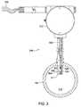
- FIG. 3is a partial section view of the infrared optical detector having a probe end inserted into the conduit, in accordance with an embodiment of the present invention.
- FIG. 4is an exploded view of internal components of the infrared optical detector illustrated in FIG. 3 , in accordance with an embodiment of the present invention.
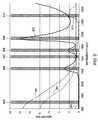
- FIG. 5is a graph illustrating absorption of two types of oil, water, condensate, and methanol for a near infrared region and wavelengths of the near infrared region selected for interrogation via channels of the infrared optical detector, in accordance with an embodiment of the present invention.
- FIG. 6is a flow chart illustrating example operations for calculating individual flow rates for gas, water, and oil in the presence of an injected hydrate inhibitor, in accordance with an embodiment of the present invention.
- Embodiments of the inventiongenerally relate to subsea multiphase flow meters capable of determining phase fractions (relative concentrations) within a multiphase fluid mixture, in the presence of an injected hydrate inhibitor. Combining this phase fraction information with a hydrate inhibitor injection rate (HIIR) enables resolving oil and water flow rates for the phase fractions.
- HIIRhydrate inhibitor injection rate
- a riser 104may extend from a vessel 102 at the surface of the sea to a subsea well 112 at the sea floor. It will be readily apparent to those skilled in the art that the diameter of the riser 104 may be varied as desired, to typically coincide with the inner diameter of a bore 114 of the subsea well 112 containing a fluid flow 116 as depicted by arrows.
- the subsea production system 100may comprise multiple subsea wells 112 .
- a subsea tree 108may be disposed above the subsea well 112 and connected to create a high pressure wellhead.
- the subsea tree 108may be a conventional horizontal or vertical production tree and may comprise multiple valves 110 .
- the subsea production system 100may comprise a utility umbilical 106 , wherein the umbilical 106 may contain a number of lines bundled together to provide electrical power, control, hydraulic power, fiber optics communication, chemical transportation, or other functionalities.
- the umbilical 106may include a chemical injection tubing or service line for transmitting hydrate inhibitors (e.g., methanol, ethanol, or glycol) to equipment of the subsea production system 100 , wherein the inhibitors may be designed and provided in order to prevent, or at least significantly reduce, the formation of solids, such as hydrates, in the fluid flow 116 .
- the hydrate inhibitormay be injected through a valve 110 of the subsea tree 108 , such as a kill wing valve, wherein a hydrate inhibitor injection rate (HIIR) may be controlled.
- a valve 110 of the subsea tree 108such as a kill wing valve
- FIG. 2illustrates a flow rate measuring system 200 comprising a Venturi-based meter 202 and an infrared optical detector 204 , which may be inserted in series with the riser 104 containing a fluid flow 116 as depicted by the arrows.
- the flow rate measuring system 200may be disposed in series with a conduit or a pipeline further upstream or downstream and coupled to a subsea control module for controlling the well 112 , e.g., by increasing or decreasing production.
- the infrared optical detector 204may be positioned upstream or downstream of the Venturi-based meter 202 .
- the flow rate measuring system 200 along with the HIIRmay enable determination of individual flow rates for gas, water, and oil, as will be further discussed.
- Various differential pressure devicessuch as the Venturi-based meter 202 , Venturi tubes, nozzles, orifice plates, and V-cones, utilize a change in flow cross-sectional area to produce changes in velocity and pressure of the fluid flow 116 according to conservation of energy and mass as the fluid flow 116 passes through such devices. Any of these differential pressure devices may therefore provide a differential pressure measurement suitable for applying in equations relating to the conservation of energy and mass in order to determine a property, such as total volume flow rate, of the fluid flow 116 . Calculations shown hereinafter refer to the Venturi-based meter 202 as an example way to determine the total volume flow rate while similar modified equations may derive the same results with other ones of the differential pressure devices.
- the Venturi-based meter 202includes first and second ports 206 , 208 which may be exposed to pressures of the fluid flow 116 that traverses through a converging section 210 into a throat section 212 .
- the change in flow cross-sectional areamay be brought about with a curved inlet section (as in an ISA-1932 nozzle) or with an abrupt change (as in an orifice plate) in some to create a measurable pressure difference.
- the divergent (outlet) section 214which aids in maximizing pressure recovery, may be designed differently or be altogether non-existent.
- the Venturi-based meter 202defines a differential pressure sensing meter between the first port 206 which may be disposed upstream of the converging section 210 and the second port 208 which may be located in the throat section 212 .
- FIG. 3illustrates the infrared optical detector 204 disposed on the riser 104 or other conduit that carries the fluid flow 116 therein.
- the detector 204may operate based on principles of spectroscopy by relying on differences in absorption between oil, water, and hydrate inhibitor of near infrared light.
- U.S. Patent Publication No. 2007/0114372which is herein incorporated by reference, describes an infrared optical fiber system capable of determining, for example, the percentages of water, oil, and hydrate inhibitor.
- a probe end 302 of the detector 204may be inserted into the riser 104 such that a sampling region 304 may be preferably located near the wall of the riser 104 .
- a body portion 312 of the detector 204may be coupled to the probe end 302 and may house electronics (not shown) outside of the riser 104 .
- the detector 204may further comprise a broad band infrared source 311 coupled to a power supply line 310 and located on an opposite side of the sampling region 304 from a collimator 306 that may be coupled to the body portion 312 by optical outputs 309 connected thereto by a common connector 308 such as a SubMiniature Version A (SMA) connector.
- the source 311may comprise a tungsten halogen lamp capable of emitting light in a range of wavelengths that includes particular wavelengths selected for interrogation as discussed in detail below.
- the source 311may comprise multiple lamps arranged adjacent to each other.
- Input and output wiring connections 316may lead from the body portion 312 of the detector 204 for providing power to the detector 204 and communication with the control module, which may be located subsea for some embodiments, and on the vessel 102 for other embodiments.
- FIG. 4illustrates internal components of the infrared optical detector 204 in an exploded view. These components may comprise the source 311 , a parabolic (or elliptic) reflector 400 for directing light from the source 311 , first and second sapphire plugs 402 , 404 , the collimator 306 and the optical outputs 309 that couple the collimator 306 to infrared filters 411 .
- An area between the sapphire plugs 402 , 404may define the sampling region 304 where fluid of the fluid flow 116 may flow across as indicated by arrow 403 .
- light from the source 311may pass through the first sapphire plug 402 and through the fluid of the fluid flow 116 where the light may be attenuated prior to passing through the second sapphire plug 404 .
- Unique absorption characteristics of the various constituents of the fluid flow 116may cause at least some of the attenuation.
- the collimator 306 adjacent the second sapphire plug 404may focus and concentrate the attenuated light into optical outputs 309 via the common connector 308 .
- the optical outputs 309typically comprise a multitude of optical fibers that may be divided into groups 309 a - f . The exact number of fibers and/or groups formed may vary for different embodiments.
- Each of the six groups 309 a - fmay connect to a housing 410 via a connector 406 such as an SMA connector.
- a photo diode 413may produce an electrical signal proportional to the light received from a respective one of the groups 309 a - f of the optical outputs 309 after passing through a respective one of the filters 411 .
- a logamp circuit(not shown) may measure the electrical signals to give up to five decades of range.
- Each of the filters 411may filter out all but a desired narrow band of infrared radiation. Since each of the filters 411 may discriminate for a selected wavelength band that is unique to that filter, each of the groups 309 a - f may represent a different channel that may provide a total attenuation signal 414 indicative of the total attenuation of the light at the wavelengths of that particular filter. Thus, the signals 414 a - f from the six channels may represent transmitted radiation at multiple different desired wavelength bands.
- absorption-based attenuation associated with that one wavelengthmay not be readily distinguished from other non-absorption-based attenuation that may introduce errors in an absorption measurement.
- using multiple simultaneous wavelength measurements provided by the signals 414 a - f from the different channelsmay enable non-wavelength-dependent attenuation, such as attenuation caused by common forms of scattering, to be subtracted out of the measurements.
- An appropriate algorithmmay remove these non-absorption background influences based on the fact that the non-wavelength-dependent attenuation may provide the same contribution at each wavelength and thence at each channel regardless of wavelength-dependent absorption. Thus, comparing the signals 414 a - f from each channel at their unique wavelengths may enable correction for non-wavelength-dependent attenuation.
- selection of the filters 411may determine the respective wavelength for each of the multiple simultaneous wavelength measurements associated with the signals 414 a - f from the different channels. Accordingly, the different channels may enable monitoring of wavelengths at absorbent peaks of the constituents of the fluid flow 116 , such as water absorbent peaks in addition to oil absorbent peaks, based on the wavelengths filtered. To generally increase resolution, a minute change in the property being measured may create a relatively large signal.
- the different channelsmay provide sensitivity for the detector across a full range of cuts of the substance within the flow, such as from 0.0% to 100% phase fraction of the substance.
- channel(s) with wavelengths at water absorbent peaksmay provide increased sensitivity for low water fractions while channel(s) with wavelengths at oil absorbent peaks may provide increased sensitivity for high water fractions.
- Another benefit of the multiple simultaneous wavelength measurements provided by the signals 414 a - f from the different channelsmay include the ability to accurately calibrate the detector 204 with a small amount of pure fluid. Thus, calibration of the detector 204 need not require a reference cut.
- FIG. 5illustrates a graph of absorption versus wavelength for two types of oil indicated by curves 501 , 502 , water represented by curve 503 , condensate denoted by curve 504 , and methanol denoted by curve 511 , for a near infrared region.
- Gasprovides relatively low absorption at typical test line pressures and has accordingly been omitted from the graph. Gas-based absorption is linearly related to pressure, however, so at elevated pressures accounting for the associated attenuation may improve performance.
- the graphshows six preferred wavelength bands 505 - 510 for filtering by the filters 411 in order to provide six channels of the infrared optical detector 204 . Other wavelength bands may be selected without departing from the scope of the invention.
- the detector 204essentially ignores salinity changes since typical salinity levels may have negligible effect on water absorption over the spectral region of interest.
- a first wavelength band 505includes wavelengths within a range of approximately 900 nanometers (nm) to 1200 nm, for example about 950 nm, where there may be an oil absorbent peak.
- a second wavelength band 506includes wavelengths centered around 1450 nm where there may be a water absorbent peak.
- a trough around 1650 nmprovides another interrogation region where a third wavelength band 507 generally is centered.
- a fourth wavelength band 508generally includes a peak centered about 1730 nm that may be fundamentally associated with carbon-hydrogen bonds for the two types of oil indicated by curves 501 , 502 and the condensate denoted by curve 504 .
- a sixth wavelength band 510generally includes a peak centered around 2310 nm that may have similar absorbance for water denoted by curve 503 , condensate denoted by curve 504 , and methanol denoted by curve 505 .
- the substantial similarities and/or differences in the absorption of the different phases at each of the bands 505 - 510may further enable their differentiation from one another with the infrared optical detector 204 .
- FIG. 6shows a flow chart illustrating use of the infrared optical detector 204 for three phase fraction measuring along with employment of a hydrate inhibitor injection rate (HIIR) and the Venturi-based meter 202 to calculate individual flow rates for gas, water, and oil.
- the operationsmay begin at 602 by determining the HIIR.
- the hydrate inhibitormay be injected through a valve 110 of the subsea tree 108 , such as a kill wing valve.
- the HIIRmay be determined by measuring the amount of hydrate inhibitor injected through the valve 110 .
- the HIIRmay be known without measuring.
- readings from the infrared optical detector 204may enable determination of relative concentrations of liquids including a relative concentration of the hydrate inhibitor.
- Making five or more separate absorbance measurements at five or more different wavelengthsmay enable solving for five unknowns (x o , x w , x g , x h , and S) in Equation 1.
- the relative liquid component fractions ( ⁇ o , ⁇ w , ⁇ h )are direct functions of the component pathlengths (x o , x w , x h ) and hence can be calculated.
- using the HIIR (or Q h ) and the liquid component fractions ( ⁇ o , ⁇ w , ⁇ h )may enable solving for an oil flow rate (Q o ) and a water flow rate (Q w ) using the following two equations having these two values as the only unknowns:
- the Venturi-based meter 202may provide fluid pressure related data to enable determination of a total volume flow rate (liquid+gas) of the mixture (Q t ) using the following equation:
- K gK g ⁇ A t ⁇ m 2 ⁇ ⁇ ⁇ ⁇ P , ( Equation ⁇ ⁇ 5 )
- K gis a flow coefficient (determined empirically or from published data)
- ⁇ Pis the measured differential pressure
- ⁇ mis the mixture density
- a tis the flow cross-sectional area of the throat section of the Venturi-based meter 202 .
- the Venturi-based meter 202may rely on solving for the total volume flow rate (Q t ) (in Equation 5) given a mixture density ( ⁇ m ) determined by the respective liquid phase fractions ( ⁇ o , ⁇ w and ⁇ h , measured in the relative concentration determination step 604 ), gas fraction, and known component densities ( ⁇ g , ⁇ w , ⁇ h , ⁇ g ). Calculation of ⁇ m , due to its dependence on gas fraction, may be carried out iteratively between Equations 5, 6 and 7.
- the Venturi-based meter 202may rely on solving for the total volume flow rate (Q t ) and the gas flow rate (Q g ) using equations other than Equation 5 and Equation 6—such as empirical correlations and/or published data on Venturi-based meters in multiphase-flows.
- the Venturi-based meter 202may rely on solving for the total volume flow rate (Q t ) and the gas flow rate (Q g ) using equations other than Equation 5 and Equation 6—such as “over-reading” correlations (empirical and/or published) of Venturi-based meters 202 in wet-gas flows.
- the subsea control modulemay efficiently control the well 112 based on at least the liquid flow rates by increasing or decreasing production.
- the HIIRmay be controlled and adjusted based on the relative concentrations of the liquids, or at least of water.
- the infrared optical detector 204may determine a quantification or relative concentration of the water based on absorbance readings from the signals. Further, an alarm, visual output, or automated corrective action can initiate upon detecting the water so that, for example, appropriate reductions in producing rate or increase in hydrate inhibitor injections can be made.
- the HIIRmay be reduced when the relative water concentration is low, but then increased when the relative concentrations of water increases, in an effort to prevent the formation of hydrates at 614 .
Landscapes
- Physics & Mathematics (AREA)
- General Physics & Mathematics (AREA)
- Fluid Mechanics (AREA)
- Spectroscopy & Molecular Physics (AREA)
- Chemical & Material Sciences (AREA)
- Life Sciences & Earth Sciences (AREA)
- Health & Medical Sciences (AREA)
- Analytical Chemistry (AREA)
- Biochemistry (AREA)
- General Health & Medical Sciences (AREA)
- Immunology (AREA)
- Pathology (AREA)
- Investigating Or Analysing Materials By Optical Means (AREA)
Abstract
Description
Ai=aoixo+awixw+agixg+ahixh+S (Equation 1),
where Aiis total absorbance at wavelength i and includes chemical (absorption) and physical (scattering) effects, aoi, awi, agi, and ahiare absorption coefficients for oil, water, gas, and hydrate inhibitor respectively at wavelength i, xo, xw, xg, and xhare pathlengths of oil, water, gas, and hydrate inhibitor, respectively, and S is a scatter contribution (wavelength independent) to overall absorbance. Making five or more separate absorbance measurements at five or more different wavelengths may enable solving for five unknowns (xo, xw, xg, xh, and S) in Equation 1. The relative liquid component fractions (αo, αw, αh) are direct functions of the component pathlengths (xo, xw, xh) and hence can be calculated.
Hence the total liquid volume rate (Qliq) may be obtained simply by adding the individual liquid component rates:
Qliq=Qo+Qw+HIIR (Equation 4).
where Kgis a flow coefficient (determined empirically or from published data), ΔP is the measured differential pressure, ρmis the mixture density, and Atis the flow cross-sectional area of the throat section of the Venturi-based
Qg=Qt−Qliq (Equation 6),
and the gas fraction (αg) can be calculated using:
Claims (17)
Priority Applications (3)
| Application Number | Priority Date | Filing Date | Title |
|---|---|---|---|
| US12/860,720US9002650B2 (en) | 2010-08-20 | 2010-08-20 | Multiphase flow meter for subsea applications using hydrate inhibitor measurement |
| CA2749621ACA2749621C (en) | 2010-08-20 | 2011-08-17 | Multiphase flow meter for subsea applications using hydrate inhibitor measurement |
| GB1114283.3AGB2482984B (en) | 2010-08-20 | 2011-08-19 | Multiphase flow meter for subsea applications using hydrate inhibitor measurement |
Applications Claiming Priority (1)
| Application Number | Priority Date | Filing Date | Title |
|---|---|---|---|
| US12/860,720US9002650B2 (en) | 2010-08-20 | 2010-08-20 | Multiphase flow meter for subsea applications using hydrate inhibitor measurement |
Publications (2)
| Publication Number | Publication Date |
|---|---|
| US20120046870A1 US20120046870A1 (en) | 2012-02-23 |
| US9002650B2true US9002650B2 (en) | 2015-04-07 |
Family
ID=44800534
Family Applications (1)
| Application Number | Title | Priority Date | Filing Date |
|---|---|---|---|
| US12/860,720Active2033-03-25US9002650B2 (en) | 2010-08-20 | 2010-08-20 | Multiphase flow meter for subsea applications using hydrate inhibitor measurement |
Country Status (3)
| Country | Link |
|---|---|
| US (1) | US9002650B2 (en) |
| CA (1) | CA2749621C (en) |
| GB (1) | GB2482984B (en) |
Cited By (5)
| Publication number | Priority date | Publication date | Assignee | Title |
|---|---|---|---|---|
| US10047303B2 (en) | 2014-10-28 | 2018-08-14 | Onesubsea Ip Uk Limited | Additive management system |
| IT201700025126A1 (en)* | 2017-03-07 | 2018-09-07 | Milano Politecnico | PROCEDURE AND DEVICE FOR MEASURING THE FLOW RATES OF NON-MIXABLE COMPONENTS OF A LIQUID-LIQUID TWO-PHASE FLOW |
| US10648841B1 (en)* | 2019-03-08 | 2020-05-12 | Saudi Arabian Oil Company | Multiphase flow meter combining extended throat venturi with microwave resonators |
| US11162893B2 (en)* | 2009-06-04 | 2021-11-02 | Pietro Fiorentini S.P.A. | Device and method for determining the composition of a mixture of fluids |
| US20240084675A1 (en)* | 2022-09-14 | 2024-03-14 | China University Of Petroleum (East China) | Apparatus for preventing and controlling secondary generation of hydrates in wellbore during depressurization exploitation of offshore natural gas hydrates and prevention and control method |
Families Citing this family (24)
| Publication number | Priority date | Publication date | Assignee | Title |
|---|---|---|---|---|
| WO2013050051A1 (en)* | 2011-10-04 | 2013-04-11 | Cameron International Corporation | Subsea retrievable pressure sensor |
| WO2013134232A2 (en)* | 2012-03-06 | 2013-09-12 | Rosemount, Inc. | Remote seal pressure measurement system for subsea use |
| US9567852B2 (en) | 2012-12-13 | 2017-02-14 | Halliburton Energy Services, Inc. | Systems and methods for measuring fluid additive concentrations for real time drilling fluid management |
| US9347310B2 (en)* | 2012-09-20 | 2016-05-24 | Weatherford Technology Holdings, Llc | Multiphase flowmeter for subsea applications |
| US9222351B2 (en) | 2012-12-13 | 2015-12-29 | Halliburton Energy Services, Inc. | Systems and methods for real-time sag detection |
| US9335438B2 (en)* | 2012-12-13 | 2016-05-10 | Halliburton Energy Services, Inc. | Systems and methods for real time monitoring of gas hydrate formation |
| US9442031B2 (en) | 2013-06-28 | 2016-09-13 | Rosemount Inc. | High integrity process fluid pressure probe |
| US9103704B2 (en) | 2013-07-25 | 2015-08-11 | General Electric Company | Holding device to hold a reflector and an electromagnetic guiding device |
| US9632071B2 (en) | 2013-07-25 | 2017-04-25 | General Electric Company | Systems and methods for analyzing a multiphase fluid |
| US9459170B2 (en) | 2013-09-26 | 2016-10-04 | Rosemount Inc. | Process fluid pressure sensing assembly for pressure transmitters subjected to high working pressure |
| GB201317486D0 (en)* | 2013-10-03 | 2013-11-20 | Steven Richard | Improvements in or related to flow metering |
| GB2530096B (en)* | 2014-09-15 | 2017-02-22 | Schlumberger Holdings | Mid-infrared hydrate inhibitor sensor |
| US9638600B2 (en) | 2014-09-30 | 2017-05-02 | Rosemount Inc. | Electrical interconnect for pressure sensor in a process variable transmitter |
| US10030511B2 (en) | 2015-06-22 | 2018-07-24 | Saudi Arabian Oil Company | Systems, methods, and computer medium to provide entropy based characterization of multiphase flow |
| US9857298B2 (en)* | 2015-07-06 | 2018-01-02 | Saudi Arabian Oil Company | Systems and methods for near-infrared based water cut monitoring in multiphase fluid flow |
| US10384161B2 (en)* | 2015-09-08 | 2019-08-20 | Saudi Arabian Oil Company | Systems and methods for accurate measurement of gas from wet gas wells |
| US10711594B2 (en) | 2015-10-23 | 2020-07-14 | Onesubsea Ip Uk Limited | Method and system for determining flow rate of water in a gas production system by incorporating characteristics of water |
| CN106680239A (en)* | 2017-02-24 | 2017-05-17 | 中国科学院广州能源研究所 | Device for performing in-situ infrared characterization on gas hydrate production and decomposition process and using method of device |
| EP3982777B1 (en)* | 2019-06-17 | 2023-06-07 | Fraunhofer-Gesellschaft zur Förderung der angewandten Forschung e.V. | Sensor module for determining an aerosol dose rate |
| US11448536B2 (en) | 2019-10-16 | 2022-09-20 | Weatherford Technology Holdings, Llc | Measuring component concentrations of nonhomogeneous immiscible mixtures in multiphase flows using near-infrared (NIR) filter photometry |
| US11885219B2 (en)* | 2020-03-23 | 2024-01-30 | Cameron International Corporation | Chemical injection system for a resource extraction system |
| GB2612756B (en)* | 2020-09-11 | 2024-10-02 | Schlumberger Technology Bv | Water detection and measurement system and method |
| WO2023285836A1 (en)* | 2021-07-16 | 2023-01-19 | AI Exploration Ltd | Apparatus and method for multiphase flowable medium analysis |
| WO2024145073A1 (en)* | 2022-12-29 | 2024-07-04 | Cameron International Corporation | Systems and methods for monitoring hydrate inhibitor concentration in aqueous solutions |
Citations (5)
| Publication number | Priority date | Publication date | Assignee | Title |
|---|---|---|---|---|
| WO2001071324A1 (en) | 2000-03-21 | 2001-09-27 | Premier Instruments, Inc. | Narrow band infrared water fraction apparatus for gas well and liquid hydrocarbon flow stream use |
| US20070114372A1 (en)* | 2005-02-24 | 2007-05-24 | John Lievois | Water detection and 3-phase fraction measurement systems |
| US20080093081A1 (en)* | 2004-09-13 | 2008-04-24 | Stoisits Richard F | Method for Managing Hydrates in Subssea Production Line |
| US20100193194A1 (en)* | 2007-09-25 | 2010-08-05 | Stoisits Richard F | Method For Managing Hydrates In Subsea Production Line |
| WO2010133348A2 (en) | 2009-05-20 | 2010-11-25 | Services Petroliers Schlumberger | System, method and apparatus for measuring multiphase flow |
- 2010
- 2010-08-20USUS12/860,720patent/US9002650B2/enactiveActive
- 2011
- 2011-08-17CACA2749621Apatent/CA2749621C/enactiveActive
- 2011-08-19GBGB1114283.3Apatent/GB2482984B/enactiveActive
Patent Citations (6)
| Publication number | Priority date | Publication date | Assignee | Title |
|---|---|---|---|---|
| WO2001071324A1 (en) | 2000-03-21 | 2001-09-27 | Premier Instruments, Inc. | Narrow band infrared water fraction apparatus for gas well and liquid hydrocarbon flow stream use |
| US20080093081A1 (en)* | 2004-09-13 | 2008-04-24 | Stoisits Richard F | Method for Managing Hydrates in Subssea Production Line |
| US20070114372A1 (en)* | 2005-02-24 | 2007-05-24 | John Lievois | Water detection and 3-phase fraction measurement systems |
| US7834312B2 (en) | 2005-02-24 | 2010-11-16 | Weatherford/Lamb, Inc. | Water detection and 3-phase fraction measurement systems |
| US20100193194A1 (en)* | 2007-09-25 | 2010-08-05 | Stoisits Richard F | Method For Managing Hydrates In Subsea Production Line |
| WO2010133348A2 (en) | 2009-05-20 | 2010-11-25 | Services Petroliers Schlumberger | System, method and apparatus for measuring multiphase flow |
Non-Patent Citations (1)
| Title |
|---|
| GB Search Report for GB Application No. 1114283.3, dated Dec. 19, 2011. |
Cited By (7)
| Publication number | Priority date | Publication date | Assignee | Title |
|---|---|---|---|---|
| US11162893B2 (en)* | 2009-06-04 | 2021-11-02 | Pietro Fiorentini S.P.A. | Device and method for determining the composition of a mixture of fluids |
| US10047303B2 (en) | 2014-10-28 | 2018-08-14 | Onesubsea Ip Uk Limited | Additive management system |
| US12398329B2 (en) | 2014-10-28 | 2025-08-26 | Onesubsea Ip Uk Limited | Additive management system |
| IT201700025126A1 (en)* | 2017-03-07 | 2018-09-07 | Milano Politecnico | PROCEDURE AND DEVICE FOR MEASURING THE FLOW RATES OF NON-MIXABLE COMPONENTS OF A LIQUID-LIQUID TWO-PHASE FLOW |
| US10648841B1 (en)* | 2019-03-08 | 2020-05-12 | Saudi Arabian Oil Company | Multiphase flow meter combining extended throat venturi with microwave resonators |
| US20240084675A1 (en)* | 2022-09-14 | 2024-03-14 | China University Of Petroleum (East China) | Apparatus for preventing and controlling secondary generation of hydrates in wellbore during depressurization exploitation of offshore natural gas hydrates and prevention and control method |
| US12000245B2 (en)* | 2022-09-14 | 2024-06-04 | China University Of Petroleum (East China) | Apparatus for preventing and controlling secondary generation of hydrates in wellbore during depressurization exploitation of offshore natural gas hydrates and prevention and control method |
Also Published As
| Publication number | Publication date |
|---|---|
| US20120046870A1 (en) | 2012-02-23 |
| CA2749621C (en) | 2014-06-03 |
| GB201114283D0 (en) | 2011-10-05 |
| CA2749621A1 (en) | 2012-02-20 |
| GB2482984B (en) | 2017-08-16 |
| GB2482984A (en) | 2012-02-22 |
Similar Documents
| Publication | Publication Date | Title |
|---|---|---|
| US9002650B2 (en) | Multiphase flow meter for subsea applications using hydrate inhibitor measurement | |
| US7834312B2 (en) | Water detection and 3-phase fraction measurement systems | |
| US9593575B2 (en) | Probe using ultraviolet and infrared radiation for multi-phase flow analysis | |
| US8285491B2 (en) | Devices and methods for quantification of liquids in gas-condensate wells | |
| US7880133B2 (en) | Optical multiphase flowmeter | |
| US9347310B2 (en) | Multiphase flowmeter for subsea applications | |
| US7233001B2 (en) | Multi-channel infrared optical phase fraction meter | |
| US11815380B2 (en) | Measuring component concentrations of nonhomogeneous immiscible mixtures in multiphase flows using near-infrared (NIR) filter photometry | |
| RU2669156C1 (en) | Flow moisture meter |
Legal Events
| Date | Code | Title | Description |
|---|---|---|---|
| AS | Assignment | Owner name:WEATHERFORD/LAMB, INC., TEXAS Free format text:ASSIGNMENT OF ASSIGNORS INTEREST;ASSIGNORS:LIEVOIS, JOHN;RAMAKRISHNAN, VIJAY;ADEJUYIGBE, BABAJIDE;REEL/FRAME:024867/0936 Effective date:20100816 | |
| FEPP | Fee payment procedure | Free format text:PAYOR NUMBER ASSIGNED (ORIGINAL EVENT CODE: ASPN); ENTITY STATUS OF PATENT OWNER: LARGE ENTITY | |
| AS | Assignment | Owner name:WEATHERFORD TECHNOLOGY HOLDINGS, LLC, TEXAS Free format text:ASSIGNMENT OF ASSIGNORS INTEREST;ASSIGNOR:WEATHERFORD/LAMB, INC.;REEL/FRAME:034526/0272 Effective date:20140901 | |
| STCF | Information on status: patent grant | Free format text:PATENTED CASE | |
| MAFP | Maintenance fee payment | Free format text:PAYMENT OF MAINTENANCE FEE, 4TH YEAR, LARGE ENTITY (ORIGINAL EVENT CODE: M1551); ENTITY STATUS OF PATENT OWNER: LARGE ENTITY Year of fee payment:4 | |
| AS | Assignment | Owner name:WELLS FARGO BANK NATIONAL ASSOCIATION AS AGENT, TEXAS Free format text:SECURITY INTEREST;ASSIGNORS:WEATHERFORD TECHNOLOGY HOLDINGS LLC;WEATHERFORD NETHERLANDS B.V.;WEATHERFORD NORGE AS;AND OTHERS;REEL/FRAME:051891/0089 Effective date:20191213 | |
| AS | Assignment | Owner name:DEUTSCHE BANK TRUST COMPANY AMERICAS, AS ADMINISTR Free format text:SECURITY INTEREST;ASSIGNORS:WEATHERFORD TECHNOLOGY HOLDINGS, LLC;WEATHERFORD NETHERLANDS B.V.;WEATHERFORD NORGE AS;AND OTHERS;REEL/FRAME:051419/0140 Effective date:20191213 Owner name:DEUTSCHE BANK TRUST COMPANY AMERICAS, AS ADMINISTRATIVE AGENT, NEW YORK Free format text:SECURITY INTEREST;ASSIGNORS:WEATHERFORD TECHNOLOGY HOLDINGS, LLC;WEATHERFORD NETHERLANDS B.V.;WEATHERFORD NORGE AS;AND OTHERS;REEL/FRAME:051419/0140 Effective date:20191213 | |
| AS | Assignment | Owner name:WEATHERFORD NETHERLANDS B.V., TEXAS Free format text:RELEASE BY SECURED PARTY;ASSIGNOR:WELLS FARGO BANK, NATIONAL ASSOCIATION;REEL/FRAME:053838/0323 Effective date:20200828 Owner name:HIGH PRESSURE INTEGRITY, INC., TEXAS Free format text:RELEASE BY SECURED PARTY;ASSIGNOR:WELLS FARGO BANK, NATIONAL ASSOCIATION;REEL/FRAME:053838/0323 Effective date:20200828 Owner name:PRECISION ENERGY SERVICES ULC, TEXAS Free format text:RELEASE BY SECURED PARTY;ASSIGNOR:WELLS FARGO BANK, NATIONAL ASSOCIATION;REEL/FRAME:053838/0323 Effective date:20200828 Owner name:WEATHERFORD TECHNOLOGY HOLDINGS, LLC, TEXAS Free format text:RELEASE BY SECURED PARTY;ASSIGNOR:WELLS FARGO BANK, NATIONAL ASSOCIATION;REEL/FRAME:053838/0323 Effective date:20200828 Owner name:WEATHERFORD CANADA LTD., TEXAS Free format text:RELEASE BY SECURED PARTY;ASSIGNOR:WELLS FARGO BANK, NATIONAL ASSOCIATION;REEL/FRAME:053838/0323 Effective date:20200828 Owner name:WEATHERFORD NORGE AS, TEXAS Free format text:RELEASE BY SECURED PARTY;ASSIGNOR:WELLS FARGO BANK, NATIONAL ASSOCIATION;REEL/FRAME:053838/0323 Effective date:20200828 Owner name:WEATHERFORD U.K. LIMITED, TEXAS Free format text:RELEASE BY SECURED PARTY;ASSIGNOR:WELLS FARGO BANK, NATIONAL ASSOCIATION;REEL/FRAME:053838/0323 Effective date:20200828 Owner name:WEATHERFORD SWITZERLAND TRADING AND DEVELOPMENT GMBH, TEXAS Free format text:RELEASE BY SECURED PARTY;ASSIGNOR:WELLS FARGO BANK, NATIONAL ASSOCIATION;REEL/FRAME:053838/0323 Effective date:20200828 Owner name:PRECISION ENERGY SERVICES, INC., TEXAS Free format text:RELEASE BY SECURED PARTY;ASSIGNOR:WELLS FARGO BANK, NATIONAL ASSOCIATION;REEL/FRAME:053838/0323 Effective date:20200828 Owner name:WILMINGTON TRUST, NATIONAL ASSOCIATION, MINNESOTA Free format text:SECURITY INTEREST;ASSIGNORS:WEATHERFORD TECHNOLOGY HOLDINGS, LLC;WEATHERFORD NETHERLANDS B.V.;WEATHERFORD NORGE AS;AND OTHERS;REEL/FRAME:054288/0302 Effective date:20200828 | |
| AS | Assignment | Owner name:WILMINGTON TRUST, NATIONAL ASSOCIATION, MINNESOTA Free format text:SECURITY INTEREST;ASSIGNORS:WEATHERFORD TECHNOLOGY HOLDINGS, LLC;WEATHERFORD NETHERLANDS B.V.;WEATHERFORD NORGE AS;AND OTHERS;REEL/FRAME:057683/0706 Effective date:20210930 Owner name:WEATHERFORD U.K. LIMITED, TEXAS Free format text:RELEASE BY SECURED PARTY;ASSIGNOR:WILMINGTON TRUST, NATIONAL ASSOCIATION;REEL/FRAME:057683/0423 Effective date:20210930 Owner name:PRECISION ENERGY SERVICES ULC, TEXAS Free format text:RELEASE BY SECURED PARTY;ASSIGNOR:WILMINGTON TRUST, NATIONAL ASSOCIATION;REEL/FRAME:057683/0423 Effective date:20210930 Owner name:WEATHERFORD SWITZERLAND TRADING AND DEVELOPMENT GMBH, TEXAS Free format text:RELEASE BY SECURED PARTY;ASSIGNOR:WILMINGTON TRUST, NATIONAL ASSOCIATION;REEL/FRAME:057683/0423 Effective date:20210930 Owner name:WEATHERFORD CANADA LTD, TEXAS Free format text:RELEASE BY SECURED PARTY;ASSIGNOR:WILMINGTON TRUST, NATIONAL ASSOCIATION;REEL/FRAME:057683/0423 Effective date:20210930 Owner name:PRECISION ENERGY SERVICES, INC., TEXAS Free format text:RELEASE BY SECURED PARTY;ASSIGNOR:WILMINGTON TRUST, NATIONAL ASSOCIATION;REEL/FRAME:057683/0423 Effective date:20210930 Owner name:HIGH PRESSURE INTEGRITY, INC., TEXAS Free format text:RELEASE BY SECURED PARTY;ASSIGNOR:WILMINGTON TRUST, NATIONAL ASSOCIATION;REEL/FRAME:057683/0423 Effective date:20210930 Owner name:WEATHERFORD NORGE AS, TEXAS Free format text:RELEASE BY SECURED PARTY;ASSIGNOR:WILMINGTON TRUST, NATIONAL ASSOCIATION;REEL/FRAME:057683/0423 Effective date:20210930 Owner name:WEATHERFORD NETHERLANDS B.V., TEXAS Free format text:RELEASE BY SECURED PARTY;ASSIGNOR:WILMINGTON TRUST, NATIONAL ASSOCIATION;REEL/FRAME:057683/0423 Effective date:20210930 Owner name:WEATHERFORD TECHNOLOGY HOLDINGS, LLC, TEXAS Free format text:RELEASE BY SECURED PARTY;ASSIGNOR:WILMINGTON TRUST, NATIONAL ASSOCIATION;REEL/FRAME:057683/0423 Effective date:20210930 | |
| MAFP | Maintenance fee payment | Free format text:PAYMENT OF MAINTENANCE FEE, 8TH YEAR, LARGE ENTITY (ORIGINAL EVENT CODE: M1552); ENTITY STATUS OF PATENT OWNER: LARGE ENTITY Year of fee payment:8 | |
| AS | Assignment | Owner name:WELLS FARGO BANK, NATIONAL ASSOCIATION, NORTH CAROLINA Free format text:PATENT SECURITY INTEREST ASSIGNMENT AGREEMENT;ASSIGNOR:DEUTSCHE BANK TRUST COMPANY AMERICAS;REEL/FRAME:063470/0629 Effective date:20230131 |