US9002437B2 - Method and system for position orientation correction in navigation - Google Patents
Method and system for position orientation correction in navigationDownload PDFInfo
- Publication number
- US9002437B2 US9002437B2US13/728,831US201213728831AUS9002437B2US 9002437 B2US9002437 B2US 9002437B2US 201213728831 AUS201213728831 AUS 201213728831AUS 9002437 B2US9002437 B2US 9002437B2
- Authority
- US
- United States
- Prior art keywords
- sensor
- sensors
- signals generated
- fields
- frequencies
- Prior art date
- Legal status (The legal status is an assumption and is not a legal conclusion. Google has not performed a legal analysis and makes no representation as to the accuracy of the status listed.)
- Active, expires
Links
Images


Classifications
- A—HUMAN NECESSITIES
- A61—MEDICAL OR VETERINARY SCIENCE; HYGIENE
- A61B—DIAGNOSIS; SURGERY; IDENTIFICATION
- A61B5/00—Measuring for diagnostic purposes; Identification of persons
- A61B5/06—Devices, other than using radiation, for detecting or locating foreign bodies ; Determining position of diagnostic devices within or on the body of the patient
- A61B5/061—Determining position of a probe within the body employing means separate from the probe, e.g. sensing internal probe position employing impedance electrodes on the surface of the body
- A61B5/062—Determining position of a probe within the body employing means separate from the probe, e.g. sensing internal probe position employing impedance electrodes on the surface of the body using magnetic field
- A—HUMAN NECESSITIES
- A61—MEDICAL OR VETERINARY SCIENCE; HYGIENE
- A61B—DIAGNOSIS; SURGERY; IDENTIFICATION
- A61B1/00—Instruments for performing medical examinations of the interior of cavities or tubes of the body by visual or photographical inspection, e.g. endoscopes; Illuminating arrangements therefor
- A61B1/313—Instruments for performing medical examinations of the interior of cavities or tubes of the body by visual or photographical inspection, e.g. endoscopes; Illuminating arrangements therefor for introducing through surgical openings, e.g. laparoscopes
- A—HUMAN NECESSITIES
- A61—MEDICAL OR VETERINARY SCIENCE; HYGIENE
- A61B—DIAGNOSIS; SURGERY; IDENTIFICATION
- A61B17/00—Surgical instruments, devices or methods
- A61B17/00234—Surgical instruments, devices or methods for minimally invasive surgery
- A—HUMAN NECESSITIES
- A61—MEDICAL OR VETERINARY SCIENCE; HYGIENE
- A61B—DIAGNOSIS; SURGERY; IDENTIFICATION
- A61B17/00—Surgical instruments, devices or methods
- A61B17/04—Surgical instruments, devices or methods for suturing wounds; Holders or packages for needles or suture materials
- A61B17/06—Needles ; Sutures; Needle-suture combinations; Holders or packages for needles or suture materials
- A—HUMAN NECESSITIES
- A61—MEDICAL OR VETERINARY SCIENCE; HYGIENE
- A61B—DIAGNOSIS; SURGERY; IDENTIFICATION
- A61B17/00—Surgical instruments, devices or methods
- A61B17/16—Instruments for performing osteoclasis; Drills or chisels for bones; Trepans
- A—HUMAN NECESSITIES
- A61—MEDICAL OR VETERINARY SCIENCE; HYGIENE
- A61B—DIAGNOSIS; SURGERY; IDENTIFICATION
- A61B17/00—Surgical instruments, devices or methods
- A61B17/28—Surgical forceps
- A—HUMAN NECESSITIES
- A61—MEDICAL OR VETERINARY SCIENCE; HYGIENE
- A61B—DIAGNOSIS; SURGERY; IDENTIFICATION
- A61B17/00—Surgical instruments, devices or methods
- A61B17/32—Surgical cutting instruments
- A—HUMAN NECESSITIES
- A61—MEDICAL OR VETERINARY SCIENCE; HYGIENE
- A61B—DIAGNOSIS; SURGERY; IDENTIFICATION
- A61B17/00—Surgical instruments, devices or methods
- A61B17/34—Trocars; Puncturing needles
- A—HUMAN NECESSITIES
- A61—MEDICAL OR VETERINARY SCIENCE; HYGIENE
- A61B—DIAGNOSIS; SURGERY; IDENTIFICATION
- A61B17/00—Surgical instruments, devices or methods
- A61B17/56—Surgical instruments or methods for treatment of bones or joints; Devices specially adapted therefor
- A61B17/58—Surgical instruments or methods for treatment of bones or joints; Devices specially adapted therefor for osteosynthesis, e.g. bone plates, screws or setting implements
- A61B17/68—Internal fixation devices, including fasteners and spinal fixators, even if a part thereof projects from the skin
- A61B17/84—Fasteners therefor or fasteners being internal fixation devices
- A61B17/846—Nails or pins, i.e. anchors without movable parts, holding by friction only, with or without structured surface
- A—HUMAN NECESSITIES
- A61—MEDICAL OR VETERINARY SCIENCE; HYGIENE
- A61B—DIAGNOSIS; SURGERY; IDENTIFICATION
- A61B17/00—Surgical instruments, devices or methods
- A61B17/56—Surgical instruments or methods for treatment of bones or joints; Devices specially adapted therefor
- A61B17/58—Surgical instruments or methods for treatment of bones or joints; Devices specially adapted therefor for osteosynthesis, e.g. bone plates, screws or setting implements
- A61B17/68—Internal fixation devices, including fasteners and spinal fixators, even if a part thereof projects from the skin
- A61B17/84—Fasteners therefor or fasteners being internal fixation devices
- A61B17/86—Pins or screws or threaded wires; nuts therefor
- A61B19/5244—
- A—HUMAN NECESSITIES
- A61—MEDICAL OR VETERINARY SCIENCE; HYGIENE
- A61B—DIAGNOSIS; SURGERY; IDENTIFICATION
- A61B34/00—Computer-aided surgery; Manipulators or robots specially adapted for use in surgery
- A61B34/20—Surgical navigation systems; Devices for tracking or guiding surgical instruments, e.g. for frameless stereotaxis
- A—HUMAN NECESSITIES
- A61—MEDICAL OR VETERINARY SCIENCE; HYGIENE
- A61B—DIAGNOSIS; SURGERY; IDENTIFICATION
- A61B6/00—Apparatus or devices for radiation diagnosis; Apparatus or devices for radiation diagnosis combined with radiation therapy equipment
- A61B6/12—Arrangements for detecting or locating foreign bodies
- A—HUMAN NECESSITIES
- A61—MEDICAL OR VETERINARY SCIENCE; HYGIENE
- A61B—DIAGNOSIS; SURGERY; IDENTIFICATION
- A61B6/00—Apparatus or devices for radiation diagnosis; Apparatus or devices for radiation diagnosis combined with radiation therapy equipment
- A61B6/54—Control of apparatus or devices for radiation diagnosis
- A—HUMAN NECESSITIES
- A61—MEDICAL OR VETERINARY SCIENCE; HYGIENE
- A61N—ELECTROTHERAPY; MAGNETOTHERAPY; RADIATION THERAPY; ULTRASOUND THERAPY
- A61N1/00—Electrotherapy; Circuits therefor
- A61N1/02—Details
- A61N1/04—Electrodes
- A61B2019/5238—
- A61B2019/5251—
- A—HUMAN NECESSITIES
- A61—MEDICAL OR VETERINARY SCIENCE; HYGIENE
- A61B—DIAGNOSIS; SURGERY; IDENTIFICATION
- A61B34/00—Computer-aided surgery; Manipulators or robots specially adapted for use in surgery
- A61B34/20—Surgical navigation systems; Devices for tracking or guiding surgical instruments, e.g. for frameless stereotaxis
- A61B2034/2046—Tracking techniques
- A61B2034/2051—Electromagnetic tracking systems
- A—HUMAN NECESSITIES
- A61—MEDICAL OR VETERINARY SCIENCE; HYGIENE
- A61B—DIAGNOSIS; SURGERY; IDENTIFICATION
- A61B90/00—Instruments, implements or accessories specially adapted for surgery or diagnosis and not covered by any of the groups A61B1/00 - A61B50/00, e.g. for luxation treatment or for protecting wound edges
- A61B90/36—Image-producing devices or illumination devices not otherwise provided for
- A61B90/37—Surgical systems with images on a monitor during operation
- A61B2090/376—Surgical systems with images on a monitor during operation using X-rays, e.g. fluoroscopy
- A—HUMAN NECESSITIES
- A61—MEDICAL OR VETERINARY SCIENCE; HYGIENE
- A61B—DIAGNOSIS; SURGERY; IDENTIFICATION
- A61B6/00—Apparatus or devices for radiation diagnosis; Apparatus or devices for radiation diagnosis combined with radiation therapy equipment
- A61B6/02—Arrangements for diagnosis sequentially in different planes; Stereoscopic radiation diagnosis
- A61B6/03—Computed tomography [CT]
- A61B6/032—Transmission computed tomography [CT]
- A—HUMAN NECESSITIES
- A61—MEDICAL OR VETERINARY SCIENCE; HYGIENE
- A61B—DIAGNOSIS; SURGERY; IDENTIFICATION
- A61B6/00—Apparatus or devices for radiation diagnosis; Apparatus or devices for radiation diagnosis combined with radiation therapy equipment
- A61B6/44—Constructional features of apparatus for radiation diagnosis
- A61B6/4429—Constructional features of apparatus for radiation diagnosis related to the mounting of source units and detector units
- A61B6/4435—Constructional features of apparatus for radiation diagnosis related to the mounting of source units and detector units the source unit and the detector unit being coupled by a rigid structure
- A61B6/4441—Constructional features of apparatus for radiation diagnosis related to the mounting of source units and detector units the source unit and the detector unit being coupled by a rigid structure the rigid structure being a C-arm or U-arm
- A—HUMAN NECESSITIES
- A61—MEDICAL OR VETERINARY SCIENCE; HYGIENE
- A61B—DIAGNOSIS; SURGERY; IDENTIFICATION
- A61B6/00—Apparatus or devices for radiation diagnosis; Apparatus or devices for radiation diagnosis combined with radiation therapy equipment
- A61B6/46—Arrangements for interfacing with the operator or the patient
- A61B6/461—Displaying means of special interest
- A61B6/463—Displaying means of special interest characterised by displaying multiple images or images and diagnostic data on one display
- A—HUMAN NECESSITIES
- A61—MEDICAL OR VETERINARY SCIENCE; HYGIENE
- A61B—DIAGNOSIS; SURGERY; IDENTIFICATION
- A61B6/00—Apparatus or devices for radiation diagnosis; Apparatus or devices for radiation diagnosis combined with radiation therapy equipment
- A61B6/48—Diagnostic techniques
- A61B6/486—Diagnostic techniques involving generating temporal series of image data
- A61B6/487—Diagnostic techniques involving generating temporal series of image data involving fluoroscopy
- A—HUMAN NECESSITIES
- A61—MEDICAL OR VETERINARY SCIENCE; HYGIENE
- A61B—DIAGNOSIS; SURGERY; IDENTIFICATION
- A61B6/00—Apparatus or devices for radiation diagnosis; Apparatus or devices for radiation diagnosis combined with radiation therapy equipment
- A61B6/52—Devices using data or image processing specially adapted for radiation diagnosis
- A61B6/5211—Devices using data or image processing specially adapted for radiation diagnosis involving processing of medical diagnostic data
- A61B6/5229—Devices using data or image processing specially adapted for radiation diagnosis involving processing of medical diagnostic data combining image data of a patient, e.g. combining a functional image with an anatomical image
- A61B6/5247—Devices using data or image processing specially adapted for radiation diagnosis involving processing of medical diagnostic data combining image data of a patient, e.g. combining a functional image with an anatomical image combining images from an ionising-radiation diagnostic technique and a non-ionising radiation diagnostic technique, e.g. X-ray and ultrasound
Definitions
- position and/or orientation informationfor a medical instrument, implant or device that is navigated or positioned (externally or internally) relative to a patient.
- position and orientation information derived from the tracked device itselfthat can be related to the image data also being acquired.
- a method performed in a medical navigation systemincludes driving a transmitter at a first frequency and at least a second frequency to generate a first and a least a second electromagnetic field, wherein the first and second frequencies are sufficiently low such that the first and second electromagnetic fields are frequency independent; receiving a first and at least a second distorted field corresponding to the first and second electromagnetic fields, respectively, with each of at least two electromagnetic (EM) sensors attached to a surgical device; generating a first and at least a second signal in response to receiving the first and second distorted fields, respectively, using each of the at least two EM sensors; and determining a distortion in the first and at least the second signals based at least on a distance between the at least two EM sensors and a difference between the first and second signals generated by each of the at least two EM sensors.
- EMelectromagnetic
- a medical navigation systemin another embodiment, includes a transmitter configured to emit electromagnetic (EM) fields in response to current at one or more frequencies; first and second EM sensors each configured to detect the EM fields emitted by the transmitter and to generate a signal representative of each detected EM field; and a computerized navigation system having one or more tangible, non-transitory, machine-readable media collectively storing instructions executable by a processor.
- EMelectromagnetic
- the machine-readable mediacollectively storing instructions executable by a processor drives the transmitter at one or more frequencies to generate one or more EM fields, wherein the one or more frequencies are sufficiently low such that the one or more EM fields are frequency independent; measures one or more signals generated by the first EM sensor in response to detecting the one or more EM fields, respectively; measures one or more signals generated by the second EM sensor in response to detecting the one or more EM fields, respectively; and calculates a distortion in at least one of the one or more signals based at least on a distance between the first and second EM sensors, a change in the one or more signals, and the frequency response of the EM sensors when driven at a frequency of approximately zero.
- Another embodimentincludes one more tangible, non-transitory, machine-readable media collectively storing instructions executable by a processor.
- the machine-readable media collectively storing instructions executable by a processordrives the transmitter at one or more frequencies to generate one or more EM fields, wherein the one or more frequencies are sufficiently low such that the one or more EM fields are frequency independent; measures one or more signals generated by the first EM sensor in response to detecting the one or more EM fields, respectively; measures one or more signals generated by the second EM sensor in response to detecting the one or more EM fields, respectively; and calculates a distortion in at least one of the one or more signals based at least on a distance between the first and second EM sensors, a change in the one or more signals, and the frequency response of the EM sensors when driven at a frequency of approximately zero.
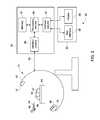
- FIG. 1is a block diagram depicting an embodiment of a fluoroscopy imaging system and a position determining system, in accordance with an embodiment of the present disclosure
- FIG. 2is a schematic diagram of an embodiment of a surgical navigation system in accordance with an aspect of the present disclosure
- FIG. 3is a flowchart depicting an embodiment of a method for adjusting the position and orientation of a device based on calculated field distortions in accordance with an aspect of the present disclosure
- FIG. 4is a flowchart depicting an embodiment of a method for calculating field distortions caused by spherical metallic objects that are symmetrically shaped in accordance with an aspect of the present disclosure
- FIG. 5is a flowchart depicting an embodiment of a method for calculating field distortions caused by non-spherical metallic objects in accordance with an aspect of the present disclosure
- FIG. 6depicts an example of an interventional device suitable for use with the position and orientation sensor assembly of FIG. 1 , in accordance with aspects of the present disclosure.
- FIG. 7depicts a distal end or tip of the interventional device of FIG. 6 , in accordance with an aspect of the present disclosure.
- a navigation systemmay generally be attached to any one or a combination of a C-arm fluoroscope, an interventional device, and a patient, or may be suitable for use in a medical device, implant or instrument.
- the navigation systemincludes one or more electromagnetic (EM) sensors that transmit and/or receive information through the radiofrequency portions of the electromagnetic spectrum.
- the EM sensorsmay also be configured to produce a magnetic field that may be used to determine spatial properties, such as position coordinates and/or orientation information.
- conductive materialse.g., metallic objects
- the present disclosureis directed toward a navigation system with a position/orientation system that is suitable for correcting position and orientation errors due to field distortions caused by the presence of conductive materials in the field.
- the position/orientation systemuses characteristic behaviors of distorted fields in order to characterize the distortion of a given field arising from the presence of metallic objects.
- the characteristic behaviors of distorted fieldsmay vary depending on the shape (e.g., spherical, irregular, and the like) of the metallic objects.
- the position/orientation systemis configured to calculate field distortions caused by spherical metallic objects that are symmetrically shaped.
- the navigation systemis driven at least two different frequencies, and the signal response emitted by the navigation system is detected.
- the position/orientation systemuses the signal response to calculate the field distortion caused by the presence of the spherical metallic object within the field.
- the calculated field distortionis used to calculate the undistorted field (e.g., undistorted transmitter response), which is in turn used to determine the actual position and orientation of the medical device, implant or instrument attached to the navigation system.
- the position/orientation systemis configured to calculate field distortions caused by metallic objects that are irregularly (e.g., non-spherical) shaped.
- at least two sensors of the navigation systemare driven at least at two different frequencies, and the signal responses emitted by the sensors are detected.
- the position/orientation systemuses the signal responses from both sensors as well as other data (e.g., a known distance between the sensors) to calculate a field distortion caused by the presence of the irregularly shaped metallic object within the field.
- the calculated field distortionis used to calculate the undistorted field (e.g., undistorted transmitter response) at each sensor, and to determine the actual position and orientation of the medical device, implant or instrument attached to the sensors, after position and orientation error compensation.
- a mathematical constructmay be used to represent the signal response received from the sensors driven at various frequencies in terms of both the distorted field (e.g., distortion caused by metallic objects) and the undistorted field (e.g., the undistorted transmitter response).
- the actual signal received from the sensorsmay be represented by a sum of two terms, both consisting of two terms—an imaginary component and a real component.
- the real component of the signale.g. field
- the distortionin general, is represented by a term, consisting of both real and imaginary part of the signal (e.g. field).
- Such a mathematical constructmay be employed to calculate, and then compensate for, the distortion caused by the metallic objects within and/or near the field of navigation.
- the imaging system 10is a fluoroscopy imaging system designed to acquire two-dimensional X-ray projection data and, in some embodiments, to process the image for mapping and registration, and to correct for position and orientation errors in accordance with present embodiments.
- the X-ray based imaging system 10includes a source of X-ray radiation 12 positioned adjacent to a collimator 14 .
- the X-ray source 12may be a standard X-ray tube or one or more solid-state X-ray emitters.
- the collimator 14permits a stream of radiation 16 to pass into a region in which a subject, such as a patient 18 , is positioned.
- a portion of the radiation 20passes through or around the patient 18 and impacts a detector array, represented generally as reference numeral 22 .
- Detector elements of the arrayproduce electrical signals that represent the intensity of the incident X-ray beam.
- the signals generated by the detector array 22may be subsequently processed to generate image or positional data that may be used in conjunction with data generated by an EM sensor 24 secured within the patient 18 .
- tracked images of an anatomy of interest (e.g., a vertebral column) 26may be registered and visualized in the depicted embodiment.
- the source 12is controlled by a system controller 28 , which furnishes both power and control signals for examination procedures.
- the detector 22is coupled to the system controller 28 , which commands acquisition of the signals generated in the detector 22 .
- system controller 28commands operation of the imaging system 10 to execute examination protocols and, in some embodiments, to process acquired data.
- system controller 28also includes signal processing circuitry, typically based upon a general purpose or application-specific digital computer, associated memory circuitry for storing programs and routines executed by the computer (such as programs and routines for implementing the present technique), as well as configuration parameters and image data, interface circuits, and so forth.
- an X-ray controller 30 disposed within the system controller 28may control the source 12 of radiation.
- the X-ray controller 30may be configured to provide power and timing signals to the X-ray source 12 .
- the system controller 28is also illustrated as including an image data acquisition system 32 .
- the detector 22is coupled to the system controller 28 , and more particularly to the image data acquisition system 32 .
- the image data acquisition system 32receives data collected by readout electronics of the detector 22 .
- the image data acquisition system 32receives sampled analog signals from the detector 22 and converts the data to digital signals for subsequent processing by processing circuitry 34 , which may, for example, be one or more processors of a general or application specific computer.
- the system controller 28also includes a position/orientation data acquisition system 36 configured to acquire position and orientation data from one or more antennas 38 .
- the one or more antennas 38detect signals and/or fields generated by some or all of the EM sensor elements 24 , 54 and 56 (depicted in FIG. 2 ). That is, the position/orientation data acquisition system 36 processes signals acquired from the antennas 38 to generate position and/or orientation information about the EM sensor 24 (and thus the anatomy of interest 26 ) as well as other EM sensors in proximity to the imaging system 10 .
- the position and/or orientation information generated by the position/orientation data acquisition system 36may be provided to the processing circuitry 34 and/or a memory 40 for subsequent processing.
- the antenna 38could either receive the signals/fields from the EM sensor elements or the antenna could generate the signals/field that are received by the EM sensor elements. Also, one of the EM sensor elements could take the place of the antenna.
- the processing circuitry 34is typically coupled to the system controller 28 .
- the data collected by the image data acquisition system 32 and/or by the position/orientation data acquisition system 36may be transmitted to the processing circuitry 34 for subsequent mapping of the EM sensor data to the fluoroscopic data, or for subsequent position and/or orientation errors caused by metallic objects within the field.
- the processing circuitry 34may include a position/orientation system 41 for correcting position and orientation errors due to field distortions caused by the presence of spherical (i.e., symmetrical) or irregular (i.e., non-symmetrical) metallic objects.
- the position/orientation system 41may apply characteristic behaviors of distorted fields to the measured data gathered by the position/orientation data acquisition system 36 in order to calculate the field distortion.
- the calculated field distortionmay then be used to calculate the undistorted field (e.g., a field unaffected by metallic objects) and to obtain the actual position and orientation of the sensors 24 , 54 , and 56 (depicted in FIG. 2 ).
- the position/orientation system 41sends the correct position and orientation of the sensors 24 , 54 , and 56 to the system controller 28 , which may then alter operational commands of the imaging system 10 in order to compensate for the position and orientation errors.
- corrected imagesmay be displayed having corrected data.
- the processing circuitry 34may include (or may communicate with) the memory 40 that stores data processed by the processing circuitry 34 or data to be processed (such as fluoroscopic images produced by the imaging of patient 18 or position/orientation data) by the processing circuitry 34 . It should be understood that any type of computer accessible memory device capable of storing the desired amount of data and/or code may be utilized by the imaging system 10 . Moreover, the memory 40 may include one or more memory devices, such as magnetic, solid state, or optical devices, of similar or different types, which may be local and/or remote to the system 10 . The memory 40 may store data, processing parameters, and/or computer programs having one or more routines for performing the processes described herein.
- the processing circuitry 34may be adapted to control features enabled by the system controller 28 , e.g., scanning operations and position/orientation data acquisition.
- the processing circuitry 34may be configured to receive commands and scanning parameters from an operator via an operator interface 42 typically equipped with, for example, a keyboard, mouse and/or other input devices. An operator may thereby control the system 10 via the input devices.
- a display 46 coupled to the operator interface 42may be utilized to observe a tracked and registered 2D or 3D scan having data corrected in accordance with the present disclosure.
- the display 46may be used to display the first position of the surgical device relative to the transmitter on a 2D or 3D representation of at least the patient and the surgical device.
- the 2D representationmay be an X-Ray image
- the 3D representationmay be of a CT image, a CT/MR image, or a combination thereof.
- an imagemay be printed by a printer 44 , which may be coupled to the operator interface 42 .
- one or more operator interfaces 42may be linked to the system 10 for outputting system parameters, requesting examinations, viewing images, and so forth.
- displays, printers, workstations, and similar devices supplied within the systemmay be local to the data acquisition components, or may be remote from these components, such as elsewhere within an institution or hospital, or in an entirely different location, linked to the image acquisition system via one or more configurable networks, such as the Internet, virtual private networks, and so forth.
- the processing circuitry 34may also be coupled to a picture archiving and communications system (PACS) 48 .
- Image data generated or processed by the processing circuitry 34may be transmitted to and stored at the PACS 48 for subsequent processing or review.
- PACS 48might be coupled to a remote client 50 , radiology department information system (RIS), hospital information system (HIS) or to an internal or external network, so that others at different locations may gain access to the image data.
- RISradiology department information system
- HIShospital information system
- FIG. 2a specific medical imaging modality based generally upon the overall system architecture outlined in FIG. 1 is depicted in FIG. 2 , wherein a surgical navigation system 52 is illustrated.
- the system 52may contain features included in system 10 illustrated in FIG. 1 . As such, those features are described using the same numerical reference.
- the navigation system 52includes tracking components that include electromagnetic (EM) sensors 24 , 54 , and 56 .
- the sensors 24 , 54 , and 56may be magnetoresistance-based sensors, or electromagnetic coil-based sensors.
- the surgical navigation system 52includes an embodiment of the X-ray imaging system 10 for acquiring and, in some embodiments, processing image data.
- surgical navigation system 52further includes a computerized navigation system 58 and workstation 60 .
- the X-ray imaging system 10is illustrated as a C-arm fluoroscopy system that includes a C-arm 62 , X-ray radiation source 12 , and X-ray detector 22 .
- the X-ray radiation source 12is mounted on the C-arm 62
- the X-ray detector 22is mounted on the C-arm 62 in an opposing location from the X-ray radiation source 12 . While in some radiographic systems the X-ray radiation source 12 and the X-ray detector 22 may be fixed, in some fluoroscopy system the C-arm 62 allows for coordinated movement of the X-ray radiation source 12 and the X-ray detector 22 about the patient 18 .
- the X-ray detector 22receives a portion the stream of radiation 20 from the X-ray source 12 that passes through the patient 18 positioned on a table 64 .
- the X-ray detector 22produces electrical signals that represent the intensity of the radiation stream. These signals are suitably acquired and processed to track and subsequently image features within the subject.
- a plurality of EM sensorsmay be fixed in relation to the fluoroscopy system.
- the EM sensor 24is fixed on the patient 18 , though it should be noted that EM sensor 24 may be fixed within the patient 18 , for example, to an internal structure of interest, such as a skeletal feature.
- EM sensors 54 and 56move in relation to the system 10 .
- the EM sensors 54 and 56may be fixed in relation to a medical (e.g., surgical) device 68 .
- the EM sensors 54 and 56are mounted on the operative end of the medical device 68 .
- Device 68may be may be any suitable device for use in a medical procedure.
- device 68may be a pointer, a drill, a guide wire, a catheter, an endoscope, a laparoscope, a biopsy needle, an ablation device or other similar devices.
- the surgical device 68may include one or more metallic materials that cause distortions in the field detected by the position/orientation system 41 .
- the EM sensors 24 , 54 and 56may be implemented as non-optical EM receivers or non-optical EM transmitters, i.e., as EM components that transmit and/or receive using portions of the EM spectrum that do not correspond to optical or visible light.
- the EM sensors 24 , 54 and 56may employ the radiofrequency (RF) portion of the electromagnetic spectrum and have a working range of between about 3 inches to about 18 inches. While any one or a combination of the EM sensors 24 , 54 and 56 may be used as transmitting or receiving coils, in one embodiment, the EM sensor 24 may be implemented as an EM transmitter, while the remaining EM sensors 54 and 56 may be implemented as EM receivers.
- RFradiofrequency
- the signals sensed by EM sensors 54 and 56 that are fixed in relation to the device 68may be used to determine the spatial properties of the device 68 , for example, the position (e.g., the X-, Y-, and Z-coordinates) and orientation (e.g., the pitch, yaw, and roll angles).
- the mutual inductance of two EM sensorsis the same, regardless as to which is the receiver and the transmitter. Therefore, relative positioning and functionality of the EM receivers and transmitters may be reversed.
- the EM sensor 24 that is fixed in relation to the patientmay be implemented as an EM receiver, while the remaining EM sensors 54 and 56 may be implemented as EM transmitters.
- any other suitable combination of EM transmitters and receiversmay be implemented as the EM sensors 24 , 54 , and 56 .
- each of the EM sensors 24 , 54 and 56may contain materials (e.g., coils, current loops, electromagnets, etc.) capable of producing a dipole magnetic field when a current is applied to or induced through them. Electromagnetic fields generated by each of the dipoles are distinguishable from one another in phase, frequency, time division multiplexing, and the like. The near-field characteristics of the electromagnetic fields may be used to determine spatial properties, such as position coordinates and/or orientation information. In some embodiments, one or more of the EM sensors 24 , 54 and 56 may employ industry-standard coil architecture (ISCA) type coils, a single dipole coil, or a combination thereof.
- ISCAindustry-standard coil architecture
- ISCA coilsgenerally may be defined as three, approximately collocated, approximately orthogonal, and approximately dipole coils.
- one or more of the EM sensors 24 , 54 and 56may be configured with a single coil that generates a single dipole magnetic field.
- one or more of the EM sensors 24 , 54 and 56may employ technologies other than a coil, including, for example, Hall Effect, magnetoresistance, or flux gate devices.
- the EM sensors 24 , 54 and 56may operate in a wired or wireless configuration.
- the electromagnetic field generated by each of the EM sensors 24 , 54 , and 56may become distorted by conductive materials near the field.
- Conductive materials that interfere with the electromagnetic fieldmay include spherical or irregular metallic objects, such as, for example, the metal of the C-arm 62 , the surgical tool to which the EM sensors 54 and 56 are attached, metal implants within the patient 18 , or the like.
- Metallic objectsmay cause two metal-related occurrences that distort the electromagnetic field and cause position and orientation errors in the navigation system 52 .
- non-magnetic metallic objectsmay introduce field distortions due to eddy currents, which are induced by metals in a time varying magnetic field.
- Eddy currentstypically produce significant distortion fields when the EM sensors 24 , 54 , and 56 of the navigation system 52 are driven at frequencies approximately higher than 500 Hz.
- ferromagnetic objectse.g., magnetic metallic objects
- the field generated by the EM sensorresponds to ferromagnetic objects in a characteristic manner (certain relation between real and imaginary parts of the induced distortion field) at low frequencies, and thus, may be used as a characteristic behavior when determining the position and orientation errors of the navigation system 52 .
- the present disclosureprovides embodiments of methods for the reduction of these types of distortions.
- the surgical navigation system 52may further include the computerized navigation system 58 .
- the computerized navigation system 58includes interface circuitry 86 for receiving tracking and imaging data, represented generally by arrow 88 .
- some or all of the tracking and imaging data 88 that is sent to the computerized navigation system 58has been processed and analyzed by the processing circuitry 34 and memory 48 of imaging system 10 .
- the computerized navigation system 58may also include processing circuitry 90 , memory unit 92 , and workstation interface circuitry 94 .
- one or more computersmay be used to implement the computerized navigation system 58 .
- the processing circuitry 90may process the tracking data so that the location of the device 68 may be tracked, mapped and registered to a pre-operative 3D scan.
- Memory unit 92may serve to save the imaging and tracking data as well as other system parameters.
- the memory unit 92may be any computer-readable medium such as an optical media (e.g., compact discs, digital video discs), a solid-state memory device (USB drive, flash drive), a hard drive, a memory card, and the like.
- the memory unit 92contains computer code that is executed by the processing circuitry 90 .
- the workstation interface circuitry 94may be configured for communicating with workstation 68 .
- the surgical navigation system 52further includes the workstation 68 , which includes a user interface 96 and a display 98 , which may or may not correspond to operator interface 42 and display 44 depicted in FIG. 1 .
- the user interface 96may include a keyboard and/or mouse, as well as other devices such as printers or other peripherals for reproducing hardcopies of the reconstructed images.
- Display 98may include one or more screens.
- the display 98may include a first screen for displaying a previously acquired image and a second screen for displaying one or more intra-operative images.
- FIG. 3is a flowchart depicting an embodiment of a method 110 for adjusting the position and orientation of a device 68 based on calculated field distortions.
- an electromagnetic fieldis generated by the navigation system 52 (shown in FIG. 2 ), such as by an EM sensor in a transmitting mode and which may be generally be attached to each of a C-arm fluoroscope, an interventional device, and a patient, or may be suitable for use in a medical device, implant or instrument.
- each of the EM sensors 24 , 54 and 56 in the navigation system 52may be capable of producing an electromagnetic field when a suitable current is applied to or induced through them.
- the currentis varied at a rate below 1 kHz, such as below 750 Hz or 500 Hz.
- each of the EM sensors 24 , 54 , and 56 of the navigation system 52may employ the radiofrequency (RF) portion of the electromagnetic spectrum, and may be implemented as either EM transmitters or EM receivers.
- RFradiofrequency
- EM sensor 24may be implemented as an EM transmitter, while the remaining EM sensors 54 and 56 may be implemented as EM receivers.
- the signals transmitted by EM sensor 24may be received by EM sensors 54 and 56 as electromagnetic data (block 114 ).
- the electromagnetic field generated by the EM sensor 24may induce a current in the EM sensors 54 and 56 , which is in turn relayed as data to the surgical navigation system 52 .
- the electromagnetic data received by EM sensors 54 and 56 that are fixed in relation to the device 68may be used to determine the spatial properties of the device 68 , for example, the position (e.g., the X-, Y-, and Z-coordinates) and orientation (e.g., the pitch, yaw, and roll angles).
- the presence of conductive materials within the fieldmay cause spatial distortions of the field generated by the EM sensor 24 , and thus, the position and orientation of the device 68 (as indicated by the signals generated at the EM sensors 54 and 56 ) may be distorted.
- the position (e.g., the X-, Y-, and Z-coordinates) and orientation (e.g., the pitch, yaw, and roll angles) data generatedmay also be distorted.
- the position/orientation system 41may be used to calculate field distortions caused by conductive materials within and/or near the field.
- the position/orientation system 41uses characteristic behaviors of distorted fields in order to calculate field distortions caused by metallic objects to avoid or correct for position and orientation errors.
- the characteristic behaviors of distorted fields for non-magnetic metallic objects and ferromagnetic objectsare generally different. For example, eddy currents, which are induced by non-magnetic metallic objects in a changing magnetic field, are generally seen when the navigation system 52 is driven at frequencies approximately higher than 500 Hz.
- the navigation system 52is driven at frequencies lower than approximately 1 kHz, such as below approximately, or between approximately 100 and 500 Hz.
- ferromagnetic objectse.g., magnetic metallic objects
- the field emitted by the transmitting EM sensore.g., EM sensor 24
- the transmitting EM sensoris driven at various frequencies below 500 Hz
- the field generated by the EM sensoris independent of frequency and responds to the ferromagnetic material in an identical manner when a scale factor is applied.
- the position/orientation system 41calculates field distortions caused by conductive materials based on the shape of the conductive materials.
- conductive materialssuch as metallic objects, may be spherically shaped (i.e., symmetrical) or irregularly shaped (i.e., non-symmetrical).
- the position/orientation system 41is configured to calculate field distortions caused by spherical metallic objects that are symmetrically shaped.
- the navigation system 52is driven at at least two different frequencies. Both frequencies are generally lower than approximately 500 Hz so that the change in response from one frequency to another can be attributed to the distortion.
- One or more receiving EM sensorsdetect the signal responses emitted by the receiving EM sensors of the navigation system 52 at each of the frequencies.
- the position/orientation system 41uses the signal responses to calculate the field distortion caused by the presence of the spherical metallic object within the field.
- characteristic behaviors of the distorted field for spherical metallic objectsare used to calculate the field distortions, as further described below with respect to FIG. 4 .
- the position/orientation system 41is configured to calculate field distortions caused by metallic objects that are irregularly (e.g., non-spherical or only partially spherically) shaped.
- the navigation system 52having at least one transmitter (e.g., EM sensor 24 ) and at least two receiving EM sensors (e.g., EM sensors 54 and 56 ), is driven at least at two different frequencies. Both frequencies are generally lower than approximately 500 Hz so that characteristic behaviors of distorted fields may be used in determining the field distortion.
- the field emitted by the transmitteris detected by at least two receiving EM sensors, such as, for example, EM sensors 54 and 56 .
- the position/orientation system 41uses the signal responses from both sensors, the undistorted component of which is frequency independent, to calculate the field distortion caused by the presence of the irregularly shaped metallic objects within the field. In yet other embodiments, the position/orientation system 41 calculates field distortions caused by conductive materials based on the characteristic behaviors of distorted fields, the shape of the conductive materials, or a combination thereof.
- the position/orientation system 41corrects the actual position and orientation data based on the previously calculated field distortion, and thus compensates for the distortions caused by spherical or irregularly shaped conductive materials within and/or near the field (block 118 ).
- the distortion calculatedmay be in the form of position (e.g., the X-, Y-, and Z-coordinates) and orientation (e.g., the pitch, yaw, and roll angles), as depicted in block 116 .
- the receiving EM sensorse.g., EM sensors 54 and 56
- the position and orientation errors contained within the received signalsis also removed.
- the position and orientation of the medical device, implant, or instrument attached to the sensors of the navigation system 52is adjusted to compensate for position and orientation errors caused by conductive materials.
- FIG. 4is a flowchart depicting an embodiment of a method 130 for calculating field distortions caused by spherical metallic objects.
- the sensors of the navigation system 52e.g., EM sensor 24
- both frequenciesare generally lower than approximately 1 kHz so that the signal variation between the two frequencies is attributable to distortion.
- the fields emitted at both frequencies by the EM sensor(s) of the navigation system 52are detected and measured (block 134 ).
- the EM sensors 54 and 56may detect the field emitted by the EM sensor 24 at both frequencies, and may generate a signal therefrom (e.g., a signal response). These signals may subsequently be measured.
- the signal responses of the EM sensors 54 and 56may be considered to include, or, in one embodiment, to consist of a real component and an imaginary component.
- the real component of the mathematical representation of the signal response representsis created by two contributions: the undistorted transmitter response (e.g., a response to the undistorted field) and the real part of the distortion field.
- the imaginary component of mathematical representation of the signal responserepresents the only field distortion caused by conductive materials within the field (e.g., distorted field).
- the signal responseis the hypothetical combination of the real component with the imaginary component, and represents the signal as it received by the EM sensors (e.g., EM sensors 54 and 56 ).
- the characteristic behaviors of spherical ferromagnetic objects in magnetic fieldsare used to calculate the field distortions they cause.
- one such characteristic behavior of spherical ferromagnetic objectsis that for frequencies lower than 500 Hz, the real component of the distortion field is very high for low frequencies and decreases in magnitude as the frequency increases. Furthermore, the imaginary component of the distortion field is small for low frequencies and increases with frequency up to a peak value before it decreases once again.
- the imaginary componente.g., distortion
- the field of the transmitteris frequency independent.
- the field generated by the EM sensoris independent of frequency and responds to the spherical ferromagnetic object in an identical manner when a scale factor is applied.
- the scale factor between the imaginary components of the signal responses at both frequenciesis calculated. Given the scale factor between the imaginary components, and based on the known correlation between the real component and the imaginary component of the signal response in the presence of spherical ferromagnetic objects at low frequencies, the field distortion can be calculated (block 138 ). Ultimately, the field distortion can be removed to obtain corrected position and orientation information.
- the signal response generated at different frequenciesis independent of frequency when the navigation system 52 is driven at frequencies lower than approximately 500 Hz, and responds to the spherical ferromagnetic object in an identical manner when a scale factor is applied.
- the undistorted fieldconsists only of a real component
- the imaginary parts of the fieldare measured directly in M 1 and M 2 and the scaling factor K can be calculated.
- the imaginary component and the real componentcan be calculated, and the field distortion can be determined.
- the calculated field distortion data(block 138 ) is used by the position/orientation system 41 to calculate the actual field (e.g., undistorted transmitter response) (block 118 ). Furthermore, once the actual position and orientation coordinates of the EM sensors 24 , 54 , and 56 are determined, the position and orientation of the device 68 , implant or instrument in communication with the navigation system 52 is adjusted to compensate for position and orientation errors (block 142 ).
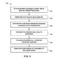
- FIG. 5is a flowchart depicting an embodiment of a method 150 for calculating field distortions caused by metallic objects that are irregularly (e.g., non-spherically) shaped.
- metallic objectsmay include for example, the metal of the C-arm 62 , the surgical tool to which the EM sensors 54 and 56 are attached, metal implants within the patient 18 , or the like.
- the transmitter of the navigation system 52e.g., EM sensor 24
- both frequenciesare generally lower than approximately 500 Hz so that the change in the field detected by receivers of the navigation system 52 is attributable to distortion.
- At least two EM sensorsmay be used to receive the field emitted by the transmitter (e.g., EM sensor 24 ) of the navigation system 52 .
- the at least two EM sensorse.g., EM sensors 54 and 56
- the variables used to calculate the distortioninclude the frequencies used to drive the transmitter, the signal responses by the receiving EM sensors (which may vary due only to changes in distortion), and a distance between the receiving sensors, which is fixed.
- the method 150includes measuring (block 154 ) a distance between at least two receiving sensors of the navigation system 52 . It should be noted that the distance may be measured at any suitable time, and not necessarily after the generation of the field by the transmitter of the navigation system 52 as depicted in the illustrated embodiment.
- the signal responses emitted by the EM sensors at both frequencies in the navigation system 52are detected and measured. Specifically, the signal response of a first receiving EM sensor (e.g., EM sensor 54 ) is measured (block 156 ) at both frequencies. Similarly, the signal response of a second receiving EM sensor (e.g., EM sensor 56 ) is measured (block 158 ) at both frequencies. As noted above, because the transmitter is driven at two or more frequencies below approximately 500 Hz, the signal response of both sensors changes due primarily (e.g., only) due to varying distortion.
- the signal responses of the EM sensors 54 and 56are generally composed of a real component and an imaginary component.
- the real component of the signal responserepresents the sum of the undistorted transmitter response (e.g., undistorted field) and the real part of the distortion response (e.g. distorted field).
- the imaginary component of the signal responserepresents the field distortion caused by conductive materials within the field (e.g., distorted field).
- the signal responseis the hypothetical combination of the real component with the imaginary component, and represents the signal as it received by the EM sensors configured to receive the signal response.
- the signal response, as it is received by the EM sensorsmay be distorted due to the presence of metallic objects within the field.
- field distortionsare calculated based on characteristic behaviors of distorted fields for irregularly shaped ferromagnetic objects. For example, in distorted fields resulting from irregular ferromagnetic objects, for frequencies lower than 500 Hz, the imaginary components of the response signal can be attributed to distortion and, if calculated, can be discarded to obtain the undistorted field. Furthermore, as described in FIG. 3 above, at frequencies lower than 500 Hz, the field of the transmitter is frequency independent. Given the measured distance between at least two sensors in the navigation system 52 , and based on the known correlation between the real component and the imaginary component of irregularly shaped ferromagnetic objects at low frequencies, the field distortion can be calculated (block 160 ).
- X 1 , X 2 , Y 1 , and Y 2are the sum of the real and imaginary components of the signal response at each sensor (e.g., distortion caused by conductive materials or distorted field).
- the imaginary components (X 1 , X 2 , Y 1 , and Y 2 ) and the real components (C 1 and C 2 )can be calculated, and the field distortion can be determined.
- the calculated field distortion for both frequencies obtained at block 160is used by the position/orientation system 41 to calculate (block 162 ) the actual field (e.g., undistorted transmitter response).
- the actual position and orientation coordinates of the device 68is determined (block 164 ).
- the position and orientation of the medical device, implant or instrument attached to the sensors of the navigation system 52may adjusted to compensate for position and orientation errors.
- the navigation system 52may cause the workstation 60 to indicate the correct position and orientation information (e.g., via display 98 ).
- FIG. 6an example of a medical device is depicted that is suitable for use with a position/orientation system 41 , and/or the navigation system 52 as discussed herein.
- the medical deviceis a catheter 170 suitable for insertion into and navigation through the vasculature of the patient 18 .
- a catheteris provided by way of example, the position/orientation system 41 discussed herein may be provided on or in various other types of surgical or interventional instruments, implants or devices.
- instruments, implants or devicesinclude, but are not limited to: implant, probe, awl, drill, aspirator, forceps, blade, screw, nail, pin, k-wire, needle, cannula, introducer, catheter, guidewire, stent, heart valve, filter, endoscope, laparoscope, or electrode, endoscopes or other intrabody camera devices, or any other suitable device for which position and orientation information may be desired during surgical or interventional use.
- the depicted catheterincludes a distal end or tip 172 in which the position/orientation system 41 may be positioned as well as a shaft 174 in communication with the tip 172 and which connects the tip 172 with a handle assembly 176 that may be used to manipulate and operate the catheter 170 .
- the handlemay communicate, such as via cable 178 , with an operator console 180 that allows a user to control certain aspects of the catheter function and operation.
- FIG. 7a close-up view of the tip 172 of catheter 170 is provided.
- two position and orientation sensor assemblies 182are depicted as being positioned within the tip 172 .
- the sensor assembliesmay be potted or otherwise affixed into the desired position within the catheter tip 172 .
- two position and orientation sensor assemblies 182are shown by way of example, in other embodiments a single sensor assembly 182 may be provided while, in yet other implementations three, four, or more sensor assemblies 182 may be provided in the medical device.
- one or both of the sensor assembly 182 and the portion of the device where the sensor assembly 182 is to be placedmay be keyed to allow placement on the position and orientation sensor assembly 182 in suitable locations and/or orientations.
Landscapes
- Health & Medical Sciences (AREA)
- Life Sciences & Earth Sciences (AREA)
- Surgery (AREA)
- Engineering & Computer Science (AREA)
- Medical Informatics (AREA)
- Biomedical Technology (AREA)
- General Health & Medical Sciences (AREA)
- Animal Behavior & Ethology (AREA)
- Veterinary Medicine (AREA)
- Public Health (AREA)
- Heart & Thoracic Surgery (AREA)
- Molecular Biology (AREA)
- Nuclear Medicine, Radiotherapy & Molecular Imaging (AREA)
- Orthopedic Medicine & Surgery (AREA)
- Pathology (AREA)
- Physics & Mathematics (AREA)
- Biophysics (AREA)
- Radiology & Medical Imaging (AREA)
- Optics & Photonics (AREA)
- High Energy & Nuclear Physics (AREA)
- Neurology (AREA)
- Oral & Maxillofacial Surgery (AREA)
- Human Computer Interaction (AREA)
- Dentistry (AREA)
- Robotics (AREA)
- Ophthalmology & Optometry (AREA)
- Vascular Medicine (AREA)
- Hematology (AREA)
- Cardiology (AREA)
- Pulmonology (AREA)
- Transplantation (AREA)
- Computer Vision & Pattern Recognition (AREA)
- Anesthesiology (AREA)
- Theoretical Computer Science (AREA)
- Artificial Intelligence (AREA)
- Physiology (AREA)
- Psychiatry (AREA)
- Signal Processing (AREA)
- Magnetic Resonance Imaging Apparatus (AREA)
- Apparatus For Radiation Diagnosis (AREA)
Abstract
Description
M1=C1+X1 (1)
where M1is the signal response at the first frequency, C1is the real component of the undistorted response (e.g., undistorted transmitter response or undistorted field), and X1is the real and imaginary component of the signal response (e.g., distortion caused by the spherical conductive materials). Furthermore, the measured signal response of the receiving EM sensors of the
M2=C1+(K*X1) (2)
where M2is the signal response of the
M1=C1+X1 (3)
The measured signal response of the receiving sensors of the navigation system52 (e.g.,
M2=C2+Y1 (4)
The measured signal response of the receiving sensors of the navigation system52 (e.g.,
M3=C1+X2 (5)
The measured signal response of the receiving sensors of the navigation system52 (e.g.,
M4=C2+Y2 (6)
Within these sets of equations, C1and C2are the real components of the signal response (e.g., undistorted field emitted by the transmitter) as received by the first and second EM sensor, respectively. Likewise, X1, X2, Y1, and Y2are the sum of the real and imaginary components of the signal response at each sensor (e.g., distortion caused by conductive materials or distorted field). Thus, given the measured signal responses M1, M2, M3and M4, and the measured distance between at least two sensors, the imaginary components (X1, X2, Y1, and Y2) and the real components (C1and C2) can be calculated, and the field distortion can be determined.
Claims (20)
Priority Applications (1)
| Application Number | Priority Date | Filing Date | Title |
|---|---|---|---|
| US13/728,831US9002437B2 (en) | 2012-12-27 | 2012-12-27 | Method and system for position orientation correction in navigation |
Applications Claiming Priority (1)
| Application Number | Priority Date | Filing Date | Title |
|---|---|---|---|
| US13/728,831US9002437B2 (en) | 2012-12-27 | 2012-12-27 | Method and system for position orientation correction in navigation |
Publications (2)
| Publication Number | Publication Date |
|---|---|
| US20140187915A1 US20140187915A1 (en) | 2014-07-03 |
| US9002437B2true US9002437B2 (en) | 2015-04-07 |
Family
ID=51017956
Family Applications (1)
| Application Number | Title | Priority Date | Filing Date |
|---|---|---|---|
| US13/728,831Active2033-06-18US9002437B2 (en) | 2012-12-27 | 2012-12-27 | Method and system for position orientation correction in navigation |
Country Status (1)
| Country | Link |
|---|---|
| US (1) | US9002437B2 (en) |
Cited By (6)
| Publication number | Priority date | Publication date | Assignee | Title |
|---|---|---|---|---|
| US20140239943A1 (en)* | 2011-08-01 | 2014-08-28 | Soreq Nuclear Research Center | Magnetic tracking system |
| US10076267B2 (en) | 2014-10-03 | 2018-09-18 | General Electric Company | Methods and systems for improved navigation |
| US11187823B2 (en)* | 2019-04-02 | 2021-11-30 | Ascension Technology Corporation | Correcting distortions |
| US11397220B2 (en) | 2019-04-02 | 2022-07-26 | Northern Digital Inc. | Distortion correction for tracking an object in a magnetic field |
| US20230051171A1 (en)* | 2019-01-01 | 2023-02-16 | Asensus Surgical Us, Inc. | Optical data transmission in a wireless power transmitter for a surgical robotic system |
| US11877806B2 (en) | 2018-12-06 | 2024-01-23 | Covidien Lp | Deformable registration of computer-generated airway models to airway trees |
Families Citing this family (135)
| Publication number | Priority date | Publication date | Assignee | Title |
|---|---|---|---|---|
| US8219178B2 (en) | 2007-02-16 | 2012-07-10 | Catholic Healthcare West | Method and system for performing invasive medical procedures using a surgical robot |
| US10893912B2 (en) | 2006-02-16 | 2021-01-19 | Globus Medical Inc. | Surgical tool systems and methods |
| US10653497B2 (en) | 2006-02-16 | 2020-05-19 | Globus Medical, Inc. | Surgical tool systems and methods |
| US10357184B2 (en) | 2012-06-21 | 2019-07-23 | Globus Medical, Inc. | Surgical tool systems and method |
| US9308050B2 (en) | 2011-04-01 | 2016-04-12 | Ecole Polytechnique Federale De Lausanne (Epfl) | Robotic system and method for spinal and other surgeries |
| US11116576B2 (en) | 2012-06-21 | 2021-09-14 | Globus Medical Inc. | Dynamic reference arrays and methods of use |
| US11317971B2 (en) | 2012-06-21 | 2022-05-03 | Globus Medical, Inc. | Systems and methods related to robotic guidance in surgery |
| US11395706B2 (en) | 2012-06-21 | 2022-07-26 | Globus Medical Inc. | Surgical robot platform |
| US10624710B2 (en) | 2012-06-21 | 2020-04-21 | Globus Medical, Inc. | System and method for measuring depth of instrumentation |
| US11399900B2 (en) | 2012-06-21 | 2022-08-02 | Globus Medical, Inc. | Robotic systems providing co-registration using natural fiducials and related methods |
| US10350013B2 (en) | 2012-06-21 | 2019-07-16 | Globus Medical, Inc. | Surgical tool systems and methods |
| US11864839B2 (en) | 2012-06-21 | 2024-01-09 | Globus Medical Inc. | Methods of adjusting a virtual implant and related surgical navigation systems |
| US11864745B2 (en) | 2012-06-21 | 2024-01-09 | Globus Medical, Inc. | Surgical robotic system with retractor |
| US11607149B2 (en) | 2012-06-21 | 2023-03-21 | Globus Medical Inc. | Surgical tool systems and method |
| US12262954B2 (en) | 2012-06-21 | 2025-04-01 | Globus Medical, Inc. | Surgical robotic automation with tracking markers |
| US12004905B2 (en) | 2012-06-21 | 2024-06-11 | Globus Medical, Inc. | Medical imaging systems using robotic actuators and related methods |
| US11974822B2 (en) | 2012-06-21 | 2024-05-07 | Globus Medical Inc. | Method for a surveillance marker in robotic-assisted surgery |
| US11298196B2 (en) | 2012-06-21 | 2022-04-12 | Globus Medical Inc. | Surgical robotic automation with tracking markers and controlled tool advancement |
| US10758315B2 (en) | 2012-06-21 | 2020-09-01 | Globus Medical Inc. | Method and system for improving 2D-3D registration convergence |
| US11253327B2 (en) | 2012-06-21 | 2022-02-22 | Globus Medical, Inc. | Systems and methods for automatically changing an end-effector on a surgical robot |
| US10136954B2 (en) | 2012-06-21 | 2018-11-27 | Globus Medical, Inc. | Surgical tool systems and method |
| EP2863827B1 (en) | 2012-06-21 | 2022-11-16 | Globus Medical, Inc. | Surgical robot platform |
| US12220120B2 (en) | 2012-06-21 | 2025-02-11 | Globus Medical, Inc. | Surgical robotic system with retractor |
| US12329593B2 (en) | 2012-06-21 | 2025-06-17 | Globus Medical, Inc. | Surgical robotic automation with tracking markers |
| US12310683B2 (en) | 2012-06-21 | 2025-05-27 | Globus Medical, Inc. | Surgical tool systems and method |
| US20150032164A1 (en) | 2012-06-21 | 2015-01-29 | Globus Medical, Inc. | Methods for Performing Invasive Medical Procedures Using a Surgical Robot |
| US11793570B2 (en) | 2012-06-21 | 2023-10-24 | Globus Medical Inc. | Surgical robotic automation with tracking markers |
| US10231791B2 (en) | 2012-06-21 | 2019-03-19 | Globus Medical, Inc. | Infrared signal based position recognition system for use with a robot-assisted surgery |
| US11045267B2 (en) | 2012-06-21 | 2021-06-29 | Globus Medical, Inc. | Surgical robotic automation with tracking markers |
| US11857149B2 (en) | 2012-06-21 | 2024-01-02 | Globus Medical, Inc. | Surgical robotic systems with target trajectory deviation monitoring and related methods |
| US11857266B2 (en) | 2012-06-21 | 2024-01-02 | Globus Medical, Inc. | System for a surveillance marker in robotic-assisted surgery |
| US9271663B2 (en)* | 2013-03-15 | 2016-03-01 | Hansen Medical, Inc. | Flexible instrument localization from both remote and elongation sensors |
| US9283048B2 (en) | 2013-10-04 | 2016-03-15 | KB Medical SA | Apparatus and systems for precise guidance of surgical tools |
| US9740821B2 (en)* | 2013-12-23 | 2017-08-22 | Biosense Webster (Israel) Ltd. | Real-time communication between medical devices over a DICOM network |
| US9241771B2 (en) | 2014-01-15 | 2016-01-26 | KB Medical SA | Notched apparatus for guidance of an insertable instrument along an axis during spinal surgery |
| WO2015121311A1 (en) | 2014-02-11 | 2015-08-20 | KB Medical SA | Sterile handle for controlling a robotic surgical system from a sterile field |
| EP3134022B1 (en) | 2014-04-24 | 2018-01-10 | KB Medical SA | Surgical instrument holder for use with a robotic surgical system |
| US10357257B2 (en) | 2014-07-14 | 2019-07-23 | KB Medical SA | Anti-skid surgical instrument for use in preparing holes in bone tissue |
| US10588541B2 (en) | 2014-07-15 | 2020-03-17 | General Electric Company | Magnetic tracker system and method for use for surgical navigation |
| EP3226781B1 (en) | 2014-12-02 | 2018-08-01 | KB Medical SA | Robot assisted volume removal during surgery |
| US10013808B2 (en) | 2015-02-03 | 2018-07-03 | Globus Medical, Inc. | Surgeon head-mounted display apparatuses |
| WO2016131903A1 (en) | 2015-02-18 | 2016-08-25 | KB Medical SA | Systems and methods for performing minimally invasive spinal surgery with a robotic surgical system using a percutaneous technique |
| US10058394B2 (en) | 2015-07-31 | 2018-08-28 | Globus Medical, Inc. | Robot arm and methods of use |
| US10646298B2 (en) | 2015-07-31 | 2020-05-12 | Globus Medical, Inc. | Robot arm and methods of use |
| US10080615B2 (en) | 2015-08-12 | 2018-09-25 | Globus Medical, Inc. | Devices and methods for temporary mounting of parts to bone |
| JP6894431B2 (en) | 2015-08-31 | 2021-06-30 | ケービー メディカル エスアー | Robotic surgical system and method |
| US10034716B2 (en) | 2015-09-14 | 2018-07-31 | Globus Medical, Inc. | Surgical robotic systems and methods thereof |
| US9771092B2 (en) | 2015-10-13 | 2017-09-26 | Globus Medical, Inc. | Stabilizer wheel assembly and methods of use |
| US11883217B2 (en) | 2016-02-03 | 2024-01-30 | Globus Medical, Inc. | Portable medical imaging system and method |
| US10448910B2 (en) | 2016-02-03 | 2019-10-22 | Globus Medical, Inc. | Portable medical imaging system |
| US10117632B2 (en) | 2016-02-03 | 2018-11-06 | Globus Medical, Inc. | Portable medical imaging system with beam scanning collimator |
| US11058378B2 (en) | 2016-02-03 | 2021-07-13 | Globus Medical, Inc. | Portable medical imaging system |
| US10842453B2 (en) | 2016-02-03 | 2020-11-24 | Globus Medical, Inc. | Portable medical imaging system |
| US10866119B2 (en) | 2016-03-14 | 2020-12-15 | Globus Medical, Inc. | Metal detector for detecting insertion of a surgical device into a hollow tube |
| EP3241518B1 (en) | 2016-04-11 | 2024-10-23 | Globus Medical, Inc | Surgical tool systems |
| CN106539624B (en)* | 2016-11-23 | 2019-12-03 | 常州朗合医疗器械有限公司 | Medical path air navigation aid, method and system for planning |
| JP7233841B2 (en) | 2017-01-18 | 2023-03-07 | ケービー メディカル エスアー | Robotic Navigation for Robotic Surgical Systems |
| US11071594B2 (en) | 2017-03-16 | 2021-07-27 | KB Medical SA | Robotic navigation of robotic surgical systems |
| US20180289432A1 (en) | 2017-04-05 | 2018-10-11 | Kb Medical, Sa | Robotic surgical systems for preparing holes in bone tissue and methods of their use |
| US11135015B2 (en) | 2017-07-21 | 2021-10-05 | Globus Medical, Inc. | Robot surgical platform |
| US11357548B2 (en) | 2017-11-09 | 2022-06-14 | Globus Medical, Inc. | Robotic rod benders and related mechanical and motor housings |
| EP3492032B1 (en) | 2017-11-09 | 2023-01-04 | Globus Medical, Inc. | Surgical robotic systems for bending surgical rods |
| US11794338B2 (en) | 2017-11-09 | 2023-10-24 | Globus Medical Inc. | Robotic rod benders and related mechanical and motor housings |
| US11134862B2 (en) | 2017-11-10 | 2021-10-05 | Globus Medical, Inc. | Methods of selecting surgical implants and related devices |
| US10952797B2 (en)* | 2018-01-02 | 2021-03-23 | Biosense Webster (Israel) Ltd. | Tracking a rigid tool in a patient body |
| US20190254753A1 (en) | 2018-02-19 | 2019-08-22 | Globus Medical, Inc. | Augmented reality navigation systems for use with robotic surgical systems and methods of their use |
| US20190282305A1 (en)* | 2018-03-16 | 2019-09-19 | Acclarent, Inc. | Navigation sleeve for medical instrument |
| US10573023B2 (en) | 2018-04-09 | 2020-02-25 | Globus Medical, Inc. | Predictive visualization of medical imaging scanner component movement |
| US11019241B1 (en)* | 2018-09-11 | 2021-05-25 | Apple Inc. | Camera lens control during magnetic interference |
| US11337742B2 (en) | 2018-11-05 | 2022-05-24 | Globus Medical Inc | Compliant orthopedic driver |
| US11278360B2 (en) | 2018-11-16 | 2022-03-22 | Globus Medical, Inc. | End-effectors for surgical robotic systems having sealed optical components |
| US11744655B2 (en) | 2018-12-04 | 2023-09-05 | Globus Medical, Inc. | Drill guide fixtures, cranial insertion fixtures, and related methods and robotic systems |
| US11602402B2 (en) | 2018-12-04 | 2023-03-14 | Globus Medical, Inc. | Drill guide fixtures, cranial insertion fixtures, and related methods and robotic systems |
| US11806084B2 (en) | 2019-03-22 | 2023-11-07 | Globus Medical, Inc. | System for neuronavigation registration and robotic trajectory guidance, and related methods and devices |
| US11317978B2 (en) | 2019-03-22 | 2022-05-03 | Globus Medical, Inc. | System for neuronavigation registration and robotic trajectory guidance, robotic surgery, and related methods and devices |
| US20200297357A1 (en) | 2019-03-22 | 2020-09-24 | Globus Medical, Inc. | System for neuronavigation registration and robotic trajectory guidance, robotic surgery, and related methods and devices |
| US11382549B2 (en) | 2019-03-22 | 2022-07-12 | Globus Medical, Inc. | System for neuronavigation registration and robotic trajectory guidance, and related methods and devices |
| US11419616B2 (en) | 2019-03-22 | 2022-08-23 | Globus Medical, Inc. | System for neuronavigation registration and robotic trajectory guidance, robotic surgery, and related methods and devices |
| US11571265B2 (en) | 2019-03-22 | 2023-02-07 | Globus Medical Inc. | System for neuronavigation registration and robotic trajectory guidance, robotic surgery, and related methods and devices |
| US11045179B2 (en) | 2019-05-20 | 2021-06-29 | Global Medical Inc | Robot-mounted retractor system |
| US11510692B2 (en)* | 2019-05-31 | 2022-11-29 | Biosense Webster (Israel) Ltd. | Ear-nose-throat (ENT) navigable shaver with ferromagnetic components |
| US11628023B2 (en) | 2019-07-10 | 2023-04-18 | Globus Medical, Inc. | Robotic navigational system for interbody implants |
| US11571171B2 (en) | 2019-09-24 | 2023-02-07 | Globus Medical, Inc. | Compound curve cable chain |
| US12396692B2 (en) | 2019-09-24 | 2025-08-26 | Globus Medical, Inc. | Compound curve cable chain |
| US11890066B2 (en) | 2019-09-30 | 2024-02-06 | Globus Medical, Inc | Surgical robot with passive end effector |
| US12329391B2 (en) | 2019-09-27 | 2025-06-17 | Globus Medical, Inc. | Systems and methods for robot-assisted knee arthroplasty surgery |
| US11426178B2 (en) | 2019-09-27 | 2022-08-30 | Globus Medical Inc. | Systems and methods for navigating a pin guide driver |
| US12408929B2 (en) | 2019-09-27 | 2025-09-09 | Globus Medical, Inc. | Systems and methods for navigating a pin guide driver |
| US11864857B2 (en) | 2019-09-27 | 2024-01-09 | Globus Medical, Inc. | Surgical robot with passive end effector |
| US11510684B2 (en) | 2019-10-14 | 2022-11-29 | Globus Medical, Inc. | Rotary motion passive end effector for surgical robots in orthopedic surgeries |
| US12133772B2 (en) | 2019-12-10 | 2024-11-05 | Globus Medical, Inc. | Augmented reality headset for navigated robotic surgery |
| US11992373B2 (en) | 2019-12-10 | 2024-05-28 | Globus Medical, Inc | Augmented reality headset with varied opacity for navigated robotic surgery |
| US12220176B2 (en) | 2019-12-10 | 2025-02-11 | Globus Medical, Inc. | Extended reality instrument interaction zone for navigated robotic |
| US12064189B2 (en) | 2019-12-13 | 2024-08-20 | Globus Medical, Inc. | Navigated instrument for use in robotic guided surgery |
| US11382699B2 (en) | 2020-02-10 | 2022-07-12 | Globus Medical Inc. | Extended reality visualization of optical tool tracking volume for computer assisted navigation in surgery |
| US12414752B2 (en) | 2020-02-17 | 2025-09-16 | Globus Medical, Inc. | System and method of determining optimal 3-dimensional position and orientation of imaging device for imaging patient bones |
| US11207150B2 (en) | 2020-02-19 | 2021-12-28 | Globus Medical, Inc. | Displaying a virtual model of a planned instrument attachment to ensure correct selection of physical instrument attachment |
| US11253216B2 (en) | 2020-04-28 | 2022-02-22 | Globus Medical Inc. | Fixtures for fluoroscopic imaging systems and related navigation systems and methods |
| US11382700B2 (en) | 2020-05-08 | 2022-07-12 | Globus Medical Inc. | Extended reality headset tool tracking and control |
| US11153555B1 (en) | 2020-05-08 | 2021-10-19 | Globus Medical Inc. | Extended reality headset camera system for computer assisted navigation in surgery |
| US11510750B2 (en) | 2020-05-08 | 2022-11-29 | Globus Medical, Inc. | Leveraging two-dimensional digital imaging and communication in medicine imagery in three-dimensional extended reality applications |
| US11317973B2 (en) | 2020-06-09 | 2022-05-03 | Globus Medical, Inc. | Camera tracking bar for computer assisted navigation during surgery |
| US12070276B2 (en) | 2020-06-09 | 2024-08-27 | Globus Medical Inc. | Surgical object tracking in visible light via fiducial seeding and synthetic image registration |
| US11382713B2 (en) | 2020-06-16 | 2022-07-12 | Globus Medical, Inc. | Navigated surgical system with eye to XR headset display calibration |
| US11877807B2 (en) | 2020-07-10 | 2024-01-23 | Globus Medical, Inc | Instruments for navigated orthopedic surgeries |
| US11793588B2 (en) | 2020-07-23 | 2023-10-24 | Globus Medical, Inc. | Sterile draping of robotic arms |
| US11737831B2 (en) | 2020-09-02 | 2023-08-29 | Globus Medical Inc. | Surgical object tracking template generation for computer assisted navigation during surgical procedure |
| US11523785B2 (en) | 2020-09-24 | 2022-12-13 | Globus Medical, Inc. | Increased cone beam computed tomography volume length without requiring stitching or longitudinal C-arm movement |
| US11911112B2 (en) | 2020-10-27 | 2024-02-27 | Globus Medical, Inc. | Robotic navigational system |
| US12076091B2 (en) | 2020-10-27 | 2024-09-03 | Globus Medical, Inc. | Robotic navigational system |
| US11941814B2 (en) | 2020-11-04 | 2024-03-26 | Globus Medical Inc. | Auto segmentation using 2-D images taken during 3-D imaging spin |
| CN112378421B (en)* | 2020-11-20 | 2022-07-08 | 山东威高医疗科技有限公司 | Device and method for testing positioning accuracy of electromagnetic navigation system |
| US11717350B2 (en) | 2020-11-24 | 2023-08-08 | Globus Medical Inc. | Methods for robotic assistance and navigation in spinal surgery and related systems |
| JP2022090630A (en)* | 2020-12-07 | 2022-06-17 | エンヴィジョン メディカル リミテッド | Insertion device positioning guide system and method |
| CN113116475B (en)* | 2020-12-31 | 2023-06-20 | 杭州堃博生物科技有限公司 | Transcatheter navigation processing method, device, medium, equipment and navigation system |
| US12161433B2 (en) | 2021-01-08 | 2024-12-10 | Globus Medical, Inc. | System and method for ligament balancing with robotic assistance |
| FR3120302B1 (en)* | 2021-03-08 | 2025-04-04 | Bonetag | imaging process of an implanted implant |
| US12150728B2 (en) | 2021-04-14 | 2024-11-26 | Globus Medical, Inc. | End effector for a surgical robot |
| US12178523B2 (en) | 2021-04-19 | 2024-12-31 | Globus Medical, Inc. | Computer assisted surgical navigation system for spine procedures |
| US11857273B2 (en) | 2021-07-06 | 2024-01-02 | Globus Medical, Inc. | Ultrasonic robotic surgical navigation |
| US11439444B1 (en) | 2021-07-22 | 2022-09-13 | Globus Medical, Inc. | Screw tower and rod reduction tool |
| US12213745B2 (en) | 2021-09-16 | 2025-02-04 | Globus Medical, Inc. | Extended reality systems for visualizing and controlling operating room equipment |
| US12238087B2 (en) | 2021-10-04 | 2025-02-25 | Globus Medical, Inc. | Validating credential keys based on combinations of credential value strings and input order strings |
| US12184636B2 (en) | 2021-10-04 | 2024-12-31 | Globus Medical, Inc. | Validating credential keys based on combinations of credential value strings and input order strings |
| US20230368330A1 (en) | 2021-10-20 | 2023-11-16 | Globus Medical, Inc. | Interpolation of medical images |
| US20230165639A1 (en) | 2021-12-01 | 2023-06-01 | Globus Medical, Inc. | Extended reality systems with three-dimensional visualizations of medical image scan slices |
| US11911115B2 (en) | 2021-12-20 | 2024-02-27 | Globus Medical Inc. | Flat panel registration fixture and method of using same |
| US12103480B2 (en) | 2022-03-18 | 2024-10-01 | Globus Medical Inc. | Omni-wheel cable pusher |
| US12048493B2 (en) | 2022-03-31 | 2024-07-30 | Globus Medical, Inc. | Camera tracking system identifying phantom markers during computer assisted surgery navigation |
| US12394086B2 (en) | 2022-05-10 | 2025-08-19 | Globus Medical, Inc. | Accuracy check and automatic calibration of tracked instruments |
| US12161427B2 (en) | 2022-06-08 | 2024-12-10 | Globus Medical, Inc. | Surgical navigation system with flat panel registration fixture |
| US20240020840A1 (en) | 2022-07-15 | 2024-01-18 | Globus Medical, Inc. | REGISTRATION OF 3D and 2D IMAGES FOR SURGICAL NAVIGATION AND ROBOTIC GUIDANCE WITHOUT USING RADIOPAQUE FIDUCIALS IN THE IMAGES |
| US12226169B2 (en) | 2022-07-15 | 2025-02-18 | Globus Medical, Inc. | Registration of 3D and 2D images for surgical navigation and robotic guidance without using radiopaque fiducials in the images |
| US12318150B2 (en) | 2022-10-11 | 2025-06-03 | Globus Medical Inc. | Camera tracking system for computer assisted surgery navigation |
| US12310676B2 (en)* | 2022-11-22 | 2025-05-27 | Medtronic Navigation, Inc. | Navigation at ultra low to high frequencies |
Citations (7)
| Publication number | Priority date | Publication date | Assignee | Title |
|---|---|---|---|---|
| US6400139B1 (en) | 1999-11-01 | 2002-06-04 | Polhemus Inc. | Methods and apparatus for electromagnetic position and orientation tracking with distortion compensation |
| US20090082989A1 (en) | 2007-09-24 | 2009-03-26 | General Electric Company | System and method for improving the distortion tolerance of an electromagnetic tracking system |
| US20100127696A1 (en) | 2008-11-26 | 2010-05-27 | General Electric Company | Magnetoresistance sensors for position and orientation determination |
| US20100168556A1 (en) | 2006-03-31 | 2010-07-01 | Koninklijke Philips Electronics N.V. | System for local error compensation in electromagnetic tracking systems |
| US7911202B2 (en) | 2007-02-05 | 2011-03-22 | General Electric Company | Electromagnetic tracking method and system |
| WO2011110966A2 (en) | 2010-03-11 | 2011-09-15 | Koninklijke Philips Electronics N.V. | Method and system for characterizing and visualizing electromagnetic tracking errors |
| US8082020B2 (en) | 2006-08-07 | 2011-12-20 | Biosense Webster, Inc. | Distortion-immune position tracking using redundant magnetic field measurements |
- 2012
- 2012-12-27USUS13/728,831patent/US9002437B2/enactiveActive
Patent Citations (8)
| Publication number | Priority date | Publication date | Assignee | Title |
|---|---|---|---|---|
| US6400139B1 (en) | 1999-11-01 | 2002-06-04 | Polhemus Inc. | Methods and apparatus for electromagnetic position and orientation tracking with distortion compensation |
| US20100168556A1 (en) | 2006-03-31 | 2010-07-01 | Koninklijke Philips Electronics N.V. | System for local error compensation in electromagnetic tracking systems |
| US8082020B2 (en) | 2006-08-07 | 2011-12-20 | Biosense Webster, Inc. | Distortion-immune position tracking using redundant magnetic field measurements |
| US7911202B2 (en) | 2007-02-05 | 2011-03-22 | General Electric Company | Electromagnetic tracking method and system |
| US20090082989A1 (en) | 2007-09-24 | 2009-03-26 | General Electric Company | System and method for improving the distortion tolerance of an electromagnetic tracking system |
| US20100127696A1 (en) | 2008-11-26 | 2010-05-27 | General Electric Company | Magnetoresistance sensors for position and orientation determination |
| WO2011110966A2 (en) | 2010-03-11 | 2011-09-15 | Koninklijke Philips Electronics N.V. | Method and system for characterizing and visualizing electromagnetic tracking errors |
| US20120323111A1 (en)* | 2010-03-11 | 2012-12-20 | Koninklijke Philips Electronics N.V. | Method and system for characterizing and visualizing electromagnetic tracking errors |
Non-Patent Citations (3)
| Title |
|---|
| Kindratenko, Volodymyr V., "A survey of electromagnetic position tracker calibration techniques," Virtual Reality: Research, Development, and Applications, 2000, pp, 169-182, vol. 5, No. 3, University of Illinois at Urbana-Champaign, Urbana, IL, USA. |
| Li, Mao et al., "A novel method of 6-DoF electromagnetic navigation system for surgical robot," Intelligent Control and Automation (WCICA), 2010, pp. 2163-2167, Shenzhen Institutes of Advanced Technology, Chinese Academy of Science, Shenzhen, China. |
| Nafis, Christopher et al., "Method for estimating dynamic EM tracking accuracy of Surgical Navigation tools," Society of Photo-Optical Instrumentation Engineers, 2006, pp. 1-17, vol. 6141, SPIE Medical Imaging 2006 Proceedings, GE Global Research, GE Healthcare, Niskayuna, NY, USA. |
Cited By (9)
| Publication number | Priority date | Publication date | Assignee | Title |
|---|---|---|---|---|
| US20140239943A1 (en)* | 2011-08-01 | 2014-08-28 | Soreq Nuclear Research Center | Magnetic tracking system |
| US9891291B2 (en)* | 2011-08-01 | 2018-02-13 | Soreq Nuclear Research Center | Magnetic tracking system |
| US10076267B2 (en) | 2014-10-03 | 2018-09-18 | General Electric Company | Methods and systems for improved navigation |
| US11877806B2 (en) | 2018-12-06 | 2024-01-23 | Covidien Lp | Deformable registration of computer-generated airway models to airway trees |
| US12310677B2 (en) | 2018-12-06 | 2025-05-27 | Covidien Lp | Deformable registration of computer-generated airway models to airway trees |
| US20230051171A1 (en)* | 2019-01-01 | 2023-02-16 | Asensus Surgical Us, Inc. | Optical data transmission in a wireless power transmitter for a surgical robotic system |
| US11819189B2 (en)* | 2019-01-01 | 2023-11-21 | Asensus Surgical Us, Inc. | Optical data transmission in a wireless power transmitter for a surgical robotic system |
| US11187823B2 (en)* | 2019-04-02 | 2021-11-30 | Ascension Technology Corporation | Correcting distortions |
| US11397220B2 (en) | 2019-04-02 | 2022-07-26 | Northern Digital Inc. | Distortion correction for tracking an object in a magnetic field |
Also Published As
| Publication number | Publication date |
|---|---|
| US20140187915A1 (en) | 2014-07-03 |
Similar Documents
| Publication | Publication Date | Title |
|---|---|---|
| US9002437B2 (en) | Method and system for position orientation correction in navigation | |
| US8694075B2 (en) | Intra-operative registration for navigated surgical procedures | |
| US20240225473A1 (en) | Method And Apparatus For Moving A Reference Device | |
| US8374678B2 (en) | Medical apparatus with image acquisition device and position determination device combined in the medical apparatus | |
| US8483800B2 (en) | Surgical navigation enabled imaging table environment | |
| US7097357B2 (en) | Method and system for improved correction of registration error in a fluoroscopic image | |
| US20060025668A1 (en) | Operating table with embedded tracking technology | |
| JP5820405B2 (en) | Local error compensation system in electromagnetic tracking system | |
| US10016148B2 (en) | Method and apparatus for correction of multiple EM sensor positions | |
| EP1912565B1 (en) | Catheter navigation system | |
| EP2030169B1 (en) | Coordinate system registration | |
| US7933730B2 (en) | Method and system for restoration of a navigation data loss in image-guided navigation | |
| US9320569B2 (en) | Systems and methods for implant distance measurement | |
| US20100069741A1 (en) | System and method for detection of electromagnetic radiation by amorphous silicon x-ray detector for metal detection in x-ray imaging | |
| US20090082665A1 (en) | System and method for tracking medical device | |
| JP5667988B2 (en) | System and method for dynamic metal strain compensation of electromagnetic tracking system | |
| US20080183064A1 (en) | Multi-sensor distortion detection method and system | |
| US20050228270A1 (en) | Method and system for geometric distortion free tracking of 3-dimensional objects from 2-dimensional measurements | |
| US20050222793A1 (en) | Method and system for calibrating deformed instruments | |
| CN110916702B (en) | Method of supporting a user, data carrier and imaging system | |
| JP2004130094A (en) | Distal targeting of locking screw in intramedullary nail | |
| Elayaperumal et al. | Autonomous real-time interventional scan plane control with a 3-D shape-sensing needle | |
| US8000890B2 (en) | Image-guided navigation employing navigated point computation method and system | |
| US8067726B2 (en) | Universal instrument calibration system and method of use | |
| US7640121B2 (en) | System and method for disambiguating the phase of a field received from a transmitter in an electromagnetic tracking system |
Legal Events
| Date | Code | Title | Description |
|---|---|---|---|
| AS | Assignment | Owner name:GENERAL ELECTRIC COMPANY, NEW YORK Free format text:ASSIGNMENT OF ASSIGNORS INTEREST;ASSIGNORS:YAROSHENKO, ANDRIY;OBI, AGHOGHO;SIGNING DATES FROM 20121221 TO 20121224;REEL/FRAME:029535/0805 | |
| FEPP | Fee payment procedure | Free format text:PAYOR NUMBER ASSIGNED (ORIGINAL EVENT CODE: ASPN); ENTITY STATUS OF PATENT OWNER: LARGE ENTITY | |
| STCF | Information on status: patent grant | Free format text:PATENTED CASE | |
| AS | Assignment | Owner name:STRYKER EUROPEAN HOLDINGS I, LLC, MICHIGAN Free format text:ASSIGNMENT OF ASSIGNORS INTEREST;ASSIGNOR:GENERAL ELECTRIC COMPANY;REEL/FRAME:046020/0621 Effective date:20171206 | |
| MAFP | Maintenance fee payment | Free format text:PAYMENT OF MAINTENANCE FEE, 4TH YEAR, LARGE ENTITY (ORIGINAL EVENT CODE: M1551); ENTITY STATUS OF PATENT OWNER: LARGE ENTITY Year of fee payment:4 | |
| AS | Assignment | Owner name:STRYKER EUROPEAN HOLDINGS III, LLC, DELAWARE Free format text:NUNC PRO TUNC ASSIGNMENT;ASSIGNOR:STRYKER EUROPEAN HOLDINGS I, LLC;REEL/FRAME:056969/0771 Effective date:20210219 Owner name:STRYKER EUROPEAN OPERATIONS HOLDINGS LLC, MICHIGAN Free format text:CHANGE OF NAME;ASSIGNOR:STRYKER EUROPEAN HOLDINGS III, LLC;REEL/FRAME:056969/0893 Effective date:20190226 | |
| MAFP | Maintenance fee payment | Free format text:PAYMENT OF MAINTENANCE FEE, 8TH YEAR, LARGE ENTITY (ORIGINAL EVENT CODE: M1552); ENTITY STATUS OF PATENT OWNER: LARGE ENTITY Year of fee payment:8 | |
| AS | Assignment | Owner name:STRYKER EUROPEAN OPERATIONS HOLDINGS LLC, MICHIGAN Free format text:CHANGE OF ADDRESS;ASSIGNOR:STRYKER EUROPEAN OPERATIONS HOLDINGS LLC;REEL/FRAME:069730/0754 Effective date:20241217 |