US9002168B2 - Cleave holder, an assembly, and methods for cleaving ends of optical fibers and securing them to a multi-optical fiber connector module - Google Patents
Cleave holder, an assembly, and methods for cleaving ends of optical fibers and securing them to a multi-optical fiber connector moduleDownload PDFInfo
- Publication number
- US9002168B2 US9002168B2US13/621,588US201213621588AUS9002168B2US 9002168 B2US9002168 B2US 9002168B2US 201213621588 AUS201213621588 AUS 201213621588AUS 9002168 B2US9002168 B2US 9002168B2
- Authority
- US
- United States
- Prior art keywords
- optical fibers
- cleave
- holder
- portions
- unitary body
- Prior art date
- Legal status (The legal status is an assumption and is not a legal conclusion. Google has not performed a legal analysis and makes no representation as to the accuracy of the status listed.)
- Active, expires
Links
- 239000013307optical fiberSubstances0.000titleclaimsabstractdescription139
- 238000000034methodMethods0.000titleclaimsdescription30
- 239000000463materialSubstances0.000claimsdescription43
- 239000000853adhesiveSubstances0.000claimsdescription42
- 230000001070adhesive effectEffects0.000claimsdescription42
- 239000002991molded plasticSubstances0.000claimsdescription7
- 239000004033plasticSubstances0.000claimsdescription7
- 229920003023plasticPolymers0.000claimsdescription7
- 239000000835fiberSubstances0.000abstractdescription93
- 230000007246mechanismEffects0.000abstractdescription4
- 230000003287optical effectEffects0.000description49
- 230000037361pathwayEffects0.000description11
- 235000014820Galium aparineNutrition0.000description9
- 240000005702Galium aparineSpecies0.000description9
- 230000008569processEffects0.000description9
- 230000005693optoelectronicsEffects0.000description5
- 230000008901benefitEffects0.000description4
- 238000004519manufacturing processMethods0.000description4
- 230000013011matingEffects0.000description4
- 229920000089Cyclic olefin copolymerPolymers0.000description3
- 239000004713Cyclic olefin copolymerSubstances0.000description3
- 230000014759maintenance of locationEffects0.000description3
- 238000005498polishingMethods0.000description3
- 239000004677NylonSubstances0.000description2
- 230000015556catabolic processEffects0.000description2
- 230000008878couplingEffects0.000description2
- 238000010168coupling processMethods0.000description2
- 238000005859coupling reactionMethods0.000description2
- 238000006731degradation reactionMethods0.000description2
- 238000003780insertionMethods0.000description2
- 230000037431insertionEffects0.000description2
- 230000004048modificationEffects0.000description2
- 238000012986modificationMethods0.000description2
- 238000000465mouldingMethods0.000description2
- 229920001778nylonPolymers0.000description2
- 239000004417polycarbonateSubstances0.000description2
- 229920000515polycarbonatePolymers0.000description2
- 239000004800polyvinyl chlorideSubstances0.000description2
- 229920001651CyanoacrylatePolymers0.000description1
- MWCLLHOVUTZFKS-UHFFFAOYSA-NMethyl cyanoacrylateChemical compoundCOC(=O)C(=C)C#NMWCLLHOVUTZFKS-UHFFFAOYSA-N0.000description1
- 238000003491arrayMethods0.000description1
- 230000008859changeEffects0.000description1
- 230000000295complement effectEffects0.000description1
- 238000007667floatingMethods0.000description1
- 239000002184metalSubstances0.000description1
- 229920000915polyvinyl chloridePolymers0.000description1
- 230000007704transitionEffects0.000description1
Images


Classifications
- G—PHYSICS
- G02—OPTICS
- G02B—OPTICAL ELEMENTS, SYSTEMS OR APPARATUS
- G02B6/00—Light guides; Structural details of arrangements comprising light guides and other optical elements, e.g. couplings
- G02B6/24—Coupling light guides
- G02B6/36—Mechanical coupling means
- G02B6/38—Mechanical coupling means having fibre to fibre mating means
- G02B6/3807—Dismountable connectors, i.e. comprising plugs
- G02B6/3833—Details of mounting fibres in ferrules; Assembly methods; Manufacture
- G02B6/3834—Means for centering or aligning the light guide within the ferrule
- G02B6/3838—Means for centering or aligning the light guide within the ferrule using grooves for light guides
- G02B6/3839—Means for centering or aligning the light guide within the ferrule using grooves for light guides for a plurality of light guides
- G—PHYSICS
- G02—OPTICS
- G02B—OPTICAL ELEMENTS, SYSTEMS OR APPARATUS
- G02B6/00—Light guides; Structural details of arrangements comprising light guides and other optical elements, e.g. couplings
- G02B6/24—Coupling light guides
- G02B6/25—Preparing the ends of light guides for coupling, e.g. cutting
- G—PHYSICS
- G02—OPTICS
- G02B—OPTICAL ELEMENTS, SYSTEMS OR APPARATUS
- G02B6/00—Light guides; Structural details of arrangements comprising light guides and other optical elements, e.g. couplings
- G02B6/24—Coupling light guides
- G02B6/36—Mechanical coupling means
- G02B6/38—Mechanical coupling means having fibre to fibre mating means
- G02B6/3807—Dismountable connectors, i.e. comprising plugs
- G02B6/3833—Details of mounting fibres in ferrules; Assembly methods; Manufacture
- G02B6/3865—Details of mounting fibres in ferrules; Assembly methods; Manufacture fabricated by using moulding techniques
- Y—GENERAL TAGGING OF NEW TECHNOLOGICAL DEVELOPMENTS; GENERAL TAGGING OF CROSS-SECTIONAL TECHNOLOGIES SPANNING OVER SEVERAL SECTIONS OF THE IPC; TECHNICAL SUBJECTS COVERED BY FORMER USPC CROSS-REFERENCE ART COLLECTIONS [XRACs] AND DIGESTS
- Y10—TECHNICAL SUBJECTS COVERED BY FORMER USPC
- Y10T—TECHNICAL SUBJECTS COVERED BY FORMER US CLASSIFICATION
- Y10T29/00—Metal working
- Y10T29/49—Method of mechanical manufacture
- Y10T29/49826—Assembling or joining
Definitions
- the inventionrelates to optical communications. More particularly, the invention relates to a cleave holder, an assembly, and methods for cleaving ends of optical fibers and securing them to a multi-optical fiber connector module.
- Multi-optical fiber connector modulesare used to mechanically couple the ends of a plurality of optical fibers to a parallel optical communications module that has a plurality of optical channels.
- the parallel optical communications modulemay be a parallel optical transceiver module having both transmit and receive optical channels, a parallel optical transmitter module having only transmit optical channels, or a parallel optical receiver module having only receive optical channels.
- a typical multi-optical fiber connector moduleincludes an optics system that couples light between the ends of the optical fibers and respective optoelectronic devices that are contained within the parallel optical communications module.
- the optoelectronic devicesare electrical-to-optical converters such as laser diodes or light-emitting diodes (LEDs).
- the optoelectronic devicesare optical-to-electrical converters such as photodiodes.
- the multi-optical fiber connector modules and the parallel optical communications modulestypically have mating features on them that allow the multi-optical fiber connector modules to be fixedly or removably mechanically coupled to one another.
- great careis taken to ensure that once the modules are mated together, very precise optical alignment exists along the optical pathways.
- the ends of the optical fibersare polished to form a flat optical surface on the end of the fiber.
- the flat optical surfaceimproves the efficiency with which light is coupled into or out of the end of the fiber.
- the process of polishing the ends of the fibersis time consuming and expensive.
- An alternative to polishing the ends of the optical fibersis to cleave them and cover the cleaved ends in a refractive index-matching adhesive material, as disclosed in U.S. Pat. No. 7,543,994 (hereinafter the '994 patent) and U.S. Pat. No. 7,553,091 (hereinafter the '091 patent), which are assigned to the assignee of the present application and which are incorporated by reference herein in their entireties.
- the adhesive materialhas an index of refraction that matches, or nearly matches, the index of refraction of the fiber cores to prevent total internal reflection from occurring at the interface between the fiber ends and the optical elements of the optics system of the connector module. Leaving the ends of the fibers in as-cleaved condition eliminates the costs associated with polishing.
- the inventionis directed to a cleave holder, an assembly, and methods.
- the cleave holdercomprises a unitary body and a cover.
- the unitary bodyhas a plurality of grooves formed in an upper surface thereof and has a plurality of reference holes formed in a lower surface thereof.
- the grooveshold length-wise portions of respective optical fibers that extend through the cleave holder.
- the coveris disposed on the unitary body such that a backside of the cover is in contact with the unitary body and with the length-wise portions of the optical fibers held in the grooves and serves to hold the length-wise portions of the optical fibers in fixed positions within the cleave holder.
- the assemblycomprises the cleave holder and a connector module.
- the connector moduleholds cleaved ends of the optical fibers that extend through the cleave holder in fixed, precise locations within the connector module.
- One of the methodsis a method of securing cleaved ends of a plurality of optical fibers to a connector module.
- the methodcomprises: providing a cleave holder having a plurality of grooves formed in an upper surface thereof and having a plurality of reference holes formed in a lower surface thereof; mounting the cleave holder on a fixture such that the reference holes formed in a body of the cleave holder mate with respective pins disposed on the fixture; disposing length-wise portions of respective optical fibers in the grooves; securing a cover of the cleave holder to the body of the cleave holder such that a backside of the cover is in contact with the body and with the length-wise portions of the optical fibers to hold the length-wise portions of the optical fibers in fixed positions within the cleave holder; providing a connector module; and securing cleaved ends of the optical fibers to fixed, precise locations within the connector module.
- One of the methodsis a method for holding a plurality of optical fibers to be stripped and cleaved.
- This methodcomprises providing the cleave holder; mounting a body of the cleave holder on a fixture such that reference holes formed in the body mate with respective pins disposed on the fixture; disposing length-wise portions of respective optical fibers in grooves formed in the body of the cleave holder; and securing a cover of the cleave holder to the body of the cleave holder such that a backside of the cover is in contact with the body and with the length-wise portions of the optical fibers disposed in the grooves to hold the length-wise portions of the optical fibers in fixed positions within the cleave holder.
- FIG. 1illustrates a side perspective view of a multi-optical fiber connector module in accordance with an illustrative embodiment.
- FIG. 2illustrates a top perspective view of the module housing of the connector module shown in FIG. 1 with the cover and the optical fibers removed.
- FIG. 3illustrates a bottom perspective view of the module housing shown in FIG. 2 .
- FIG. 4illustrates a cross-sectional side perspective view of the multi-optical fiber connector module shown in FIG. 1 .
- FIG. 5illustrates an expanded view of the portion of the connector module that is within the dashed circle 13 shown in FIG. 4 .
- FIG. 6illustrates an alternative embodiment of the module housing shown in FIG. 2 .
- FIG. 7illustrates a cross-sectional view of the multi-optical fiber connector module shown in FIG. 1 mated with a similarly-configured multi-optical fiber connector module.
- FIGS. 8A and 8Billustrate front and back perspective views, respectively, of a multi-optical fiber connector module in accordance with another illustrative embodiment.
- FIG. 9illustrates a plan view of ends of a plurality of optical fibers positioned in the V-shaped second portions of the grooves of the module housing shown in FIG. 4 .
- FIG. 10illustrates a plan view of ends of a plurality of optical fibers positioned in the V-shaped second portions of the grooves of the module housing shown in FIG. 4 .
- FIGS. 11A and 11Billustrate bottom and side cross-sectional views, respectively, of the cover shown in FIGS. 1 and 4 - 6 .
- FIG. 12illustrates a perspective view of two stacked molded plastic wheels, each of which includes eight of the module housings shown in FIG. 2 .
- FIG. 13illustrates a top perspective view of a cleave holder in accordance with an illustrative embodiment and the multi-optical fiber connector module shown in FIG. 1 .
- FIG. 14Aillustrates a top perspective view of the unitary body of the cleave holder shown in FIG. 13 with the piece of tape shown in FIG. 13 removed to show grooves that are formed in an upper surface of the body of the cleave holder.
- FIG. 14Billustrates a bottom perspective view of the body of the cleave holder shown in FIG. 13 that shows four tooling reference holes that are formed in a lower surface of the body.
- FIG. 14Cillustrates a top perspective view of the body of the cleave holder shown in FIG. 14A with fibers laid in the grooves that are formed in the upper surface of the body.
- FIG. 15illustrates a top perspective view of an assembly system that is used to assemble the multi-optical fiber connector module shown in FIG. 1 before a cover has been secured to the module.
- FIG. 16illustrates a top perspective view of the assembly system shown in FIG. 15 during assembly of the multi-optical fiber connector module shown in FIG. 1 as a cover is being secured to the module.
- a cleave holderthat allows the ends of optical fibers to be precisely stripped and cleaved and then secured at precise locations in a multi-optical fiber connector module.
- a multi-fiber connector modulewith which the cleave holder may be suitable used will be described with reference to FIGS. 1-11B .
- Illustrative embodiments of the cleave holder and the methods and systems of the inventionwill then be described with reference to FIGS. 12-16 .
- Like reference numbers in the figuresrepresent like elements, features, or components. The features in the drawings are not necessarily drawn to scale.
- FIG. 1illustrates a side perspective view of the multi-optical fiber connector module 1 in accordance with an illustrative embodiment.
- the multi-optical fiber connector module 1comprises a module housing 2 and a cover 3 and is shown in FIG. 1 connected to the cleaved and stripped ends (not shown) of a plurality of optical fibers 4 .
- FIG. 2illustrates a top perspective view of the module housing 2 shown in FIG. 1 with the cover 3 and the optical fibers 4 removed.
- FIG. 3illustrates a bottom perspective view of the module housing 2 shown in FIG. 2 .
- FIG. 4illustrates a cross-sectional side perspective view of the multi-optical fiber connector module 1 shown in FIG. 1 .
- FIG. 1illustrates a side perspective view of the multi-optical fiber connector module 1 in accordance with an illustrative embodiment.
- the multi-optical fiber connector module 1comprises a module housing 2 and a cover 3 and is shown in FIG. 1 connected to the cleaved and stripped ends (
- FIG. 5illustrates an expanded view of the portion of the module 1 that is within the dashed circle 13 shown in FIG. 4 .
- FIG. 6illustrates an alternative embodiment of the module housing 2 shown in FIG. 2 .
- FIG. 7illustrates a cross-sectional view of the multi-optical fiber connector module 1 shown in FIG. 1 mated with a similarly-configured multi-optical fiber connector module 20 . Characteristics, elements and features of the multi-optical fiber connector module 1 will now be described with reference to FIGS. 1-7 .
- the multi-fiber connector module 1has sixteen respective optical pathways, although the invention is not limited with respect to the number of optical fibers that are connected to the connector module 1 or the number of optical channels that are provided in the connector module 1 .
- the module housing 2is typically a molded, unitary plastic part, although the invention is not limited with respect to the composition of the module housing 2 .
- the cover 3is deformable to an extent and is typically made of unfilled plastic such as, for example, unfilled polyvinyl chloride (PVC), unfilled polycarbonate, unfilled cyclic olefin copolymer (COC), or unfilled nylon.
- PVCpolyvinyl chloride
- COCunfilled cyclic olefin copolymer
- the multi-optical fiber connector module 1 and the cover 3have features that are similar or identical to features of a multi-optical fiber connector module and cover that are disclosed in U.S. Pat. No. 7,543,994 (hereinafter the '994 patent) and U.S. Pat. No. 7,553,091 (hereinafter the '091 patent), which are assigned to the assignee of the present application and which are incorporated by reference herein in their entireties.
- an upper surface 2 a of the module housing 2has a cavity 5 formed therein.
- the cavity 5functions as an optical fiber holding chamber for holding the stripped and cleaved ends of the optical fibers 4 ( FIG. 1 ).
- the cavity 5has length, L, and width, W, dimensions ( FIG. 2 ) that are approximately equal to, but slightly greater than, the length and width dimensions of the cover 3 ( FIG. 1 ) so that the cover 3 can be gently placed in the cavity 5 with minimal force and held in place in the cavity 5 until the cover 3 has been secured in position with an adhesive material 7 ( FIG. 1 ).
- the cavity 5has a lower surface 5 a in which a plurality of grooves 6 ( FIG. 2 ) are formed.
- Each groove 6has a first portion 6 a and a second portion 6 b .
- the first portions 6 a of the grooves 6are generally semi-cylindrical in shape such that they are complementary in shape to the cylindrically-shaped outer surfaces of the jackets of the optical fibers 4 .
- the second portions 6 b of the grooves 6are V-shaped.
- each optical fiber 4Prior to securing the ends of the optical fibers 4 within the cavity 5 , each optical fiber 4 is cleaved and a portion of the jacket is stripped away, leaving a jacketed fiber portion 4 a and an unjacketed fiber portion 4 b , as can be seen in FIG. 4 .
- the jacketed fiber portions 4 a of the optical fibers 4are positioned in the first portions 6 a of the grooves 6 and the unjacketed fiber portions 4 b are positioned in the second portions 6 b of the grooves 6 .
- deformable features 3 a disposed on the bottom of the cover 3come into contact with the unjacketed fiber portions 4 b of the optical fibers 4 .
- the deformable features 3 aare slightly deformed by the forces exerted by the unjacketed fiber portions 4 b on the features 3 a during placement of the cover 3 in the cavity 5 .
- a soft sheet metal leaf spring(not shown) may be used during the placement process to apply an evenly-distributed force across the top surface of the cover 3 to cause the features 3 a to be deformed.
- the deformed features 3 apartially wrap around the unjacketed fiber portions 4 b such that the unjacketed fiber portions 4 b are pinned between the respective V-shaped second portions 6 b of the grooves 6 and the deformed features 3 a.
- the aforementioned adhesive material 7which is transparent to the primary wavelength of the optical signals being carried on the optical fibers 4 , is dispensed into a gap 8 that exists between a forward end 3 b of the cover 3 and a front wall 5 b that partially defines the cavity 5 .
- the adhesive material 7has an index of refraction that is equal to, or approximately equal to, the index of refraction of the cores (not shown) of the fibers 4 .
- the adhesive material 7fills any imperfections in the cleaved ends of the optical fibers 4 , thereby making the joints transparent to the optical beams so that no internal reflection occurs at this boundary.
- the adhesive material 7When the adhesive material 7 is dispensed into the gap 8 , it fills the gap 8 and flows between, and is in contact with, the bottom of the cover 3 and the unjacketed fiber portions 4 b , as shown in FIG. 4 .
- the adhesive material 7is also in contact with the walls 5 b , 5 c and 5 d ( FIG. 2 ) that define the cavity 5 .
- the adhesive material 7cures and becomes hardened, it fixedly secures the ends of the unjacketed fiber portions 4 b within the respective V-shaped second portions 6 b of the grooves 6 and fixedly secures the cover 3 to the lower surface 5 a and to the walls 5 b , 5 c and 5 d of the cavity 5 .
- the ends of the unjacketed fiber portions 4 bare adjacent to, or in contact with, the wall 5 b of the module housing 2 .
- Respective openingsare formed in the module housing 2 that extend in the axial directions of the grooves 6 from the cavity 5 through the wall 5 b and through a front surface 2 b of the module housing 2 .
- respective collimating lenses 9are disposed in the front surface 2 b of the module housing 2 .
- First and second passive fine alignment features 10extend from the front surface 2 b of the module housing 2 .
- the passive fine alignment features 10are identical in structure to one another and have stepped cylindrical shapes made up of first and second cylindrical portions 10 a and 10 b , where the first cylindrical portion 10 a has a diameter that is greater than a diameter of the second cylindrical portion 10 b .
- the passive fine alignment features 10are rounded where they transition from the second cylindrical portions 10 b to their ends 10 c .
- the passive fine alignment features 10are designed to mate with respective openings formed in another module (not shown), as will be described below in more detail.
- Providing the passive fine alignment features 10 with the stepped cylindrical shape shown in FIGS. 1-4provides some advantages over using long straight pins for this purpose.
- Long straight pinshave the potential to stick as they are being inserted into the respective reciprocally-shaped openings formed in the mating module. This potential to stick is due to the nearly-continuous contact that occurs between the surfaces of the pins and the respective openings as they engage one another. If sticking occurs, it is possible that the respective passive fine alignment features will not fully engage one another, which can result in less than perfect misalignment.
- stepped passive fine alignment features 10One advantage of the stepped passive fine alignment features 10 is that there is less of a tendency to stick during insertion into the respective openings due to there being less surface-to-surface contact during insertion. This feature ensures that full mechanical coupling will occur, which ensures that precise optical alignment will be achieved. Another advantage is that the stepped cylindrical shapes are easier and less costly to manufacture than some other shapes, such as tapered shapes, which would also work well for this purpose.
- a back side 2 c of the module housing 2has tapered snap features 2 d and 2 e located on opposite sides thereof. As will be described below in more detail, these tapered snap features 2 d and 2 e contribute to the ability of the connector module 1 to float when it is held within a plug (not shown) or receptacle (not shown).
- the term “float,” as that term is used herein,is intended to denote a limited amount of movement of an object in the X- and/or Y- and/or Z-directions of the X, Y, Z Cartesian coordinate system shown in FIG. 1 relative to another object that is positioned in the same reference frame, as will be described below in more detail.
- the module housing 2has retention features 2 f and 2 g located on opposite sides thereof that retain the connector module 1 within a receptacle (not shown) such that movement of the module 1 in the forward Z-direction indicated by arrow 12 ( FIG. 1 ) is prevented while allowing some movement in one or more other directions, as will be described below in more detail.
- the wall 5 b of the cavity 5is curved, or tilted, relative to the X-Y plane.
- the front surface 2 b of the module housing 2is in a plane that is parallel to the X-Y plane.
- the cleaved end face 4 c of the fiber 4is generally parallel to the X-Y plane. Consequently, the end face 4 c only abuts the wall 5 b at the lower edge of the end face 4 c , but is otherwise spaced apart from the wall 5 b by a small gap. This small gap ensures that the adhesive material 7 covers all, or substantially all, of the end face 4 c , thereby making the joint transparent to the optical beam. This feature prevents internal reflections from occurring at the interface between the end faces 4 c and the lenses 9 .
- FIG. 6illustrates an alternative embodiment of the module housing 2 for providing a small gap between the end faces 4 c of the fibers 4 and the wall 5 b of the cavity 5 to ensure that the adhesive material 7 (not shown) covers all, or substantially all, of the end face 4 c .
- stops 6 care formed at the ends of the grooves 6 where the grooves 6 meet the wall 5 b .
- the stops 6 care very small in size relative to the diameter of the unjacketed fiber portions 4 so that only the lower edges of the end faces 4 c abut the stops 6 c .
- the stops 6 ccause a gap to be created between the end faces 4 c and the wall 5 b that ensures that the adhesive material 7 covers all, or substantially all, of the end face 4 c , thereby making the joint transparent to the optical beam to prevent internal reflections from occurring.
- FIG. 7illustrates a cross-sectional view of the multi-optical fiber connector module 1 shown in FIG. 1 mated with a similarly-configured multi-optical fiber connector module 20 .
- the manner in which the passive fine alignment features 10 disposed on the connector module 1 mate with respective complementary-shaped openings 21 formed in the module 20can be seen in FIG. 7 .
- the complementary-shaped openings 21correspond to the passive fine alignment features of module 20 . It can be seen that when the modules 1 and 20 are in the fully-mated configuration shown in FIG. 7 , the front surface 2 b of the module 1 is in abutment with a front surface 22 of the module 20 and the optical pathways of the modules 1 and 20 are in precise optical alignment with one another.
- the module 20has lenses (not shown) that are identical to the lenses 9 of module 1 and that are in optical alignment with the lenses 9 when the modules 1 and 20 are in the fully-mated configuration shown in FIG. 7 .
- the mating of the passive fine alignment features 10 and 21effectuates the aforementioned fine alignment process, but the aforementioned coarse alignment process is effectuated by engagement of respective passive coarse alignment features (not shown) that are disposed on devices or structures that hold arrays, or banks, of the modules 1 and 20 , as will be described below in detail.
- FIGS. 8A and 8Billustrate front and back perspective views, respectively, of a multi-optical fiber connector module 30 that is identical in structure to the connector module 100 disclosed in the '091 patent. Therefore, a detailed description of the connector module 30 will not be provided herein.
- the connector module 30includes a cover (not shown) that is identical to cover 3 ( FIG. 1 ) that is secured to the module housing 31 to hold the ends of the optical fibers (not shown) in place.
- coveris not shown for ease of illustration.
- the connector module 30 shown in FIGS. 8A and 8Bhas some features or elements that are identical to features of the connector module 1 shown in FIGS. 1-7 .
- the connector module 30has tapered snap features 31 a and 31 b that perform the same functions as the snap features 2 d and 2 e of module 1 , i.e., allowing the module 30 to float to some extent.
- the connector module 30has retention features 31 c and 31 d that perform the same functions as the retention features 2 f and 2 g of module 1 , i.e., retaining the connector module 30 within a receptacle (not shown) such that movement of the module 30 in the forward Z-direction (arrow 32 in FIG.
- the connector module 30has tapered passive fine alignment features 33 that are different from the stepped passive fine alignment features 10 of the connector module 1 , but perform the same fine alignment process described above with reference to passive fine alignment features 10 .
- FIG. 9illustrates a plan view of ends 40 of a plurality of optical fibers positioned in the V-shaped second portions 6 b of the grooves 6 of the module housing 2 shown in FIG. 4 .
- the fiber ends 40are illustrated as having the same diameter.
- the horizontal line 50represents the bottom surface of a cover that is perfectly flat and does not include the deformable features 3 a of the cover 3 shown in FIG. 4 .
- all of the V-shaped second portions 6 b of the grooves 6are shown as being identically dimensioned.
- FIG. 10illustrates a plan view of ends 60 of a plurality of optical fibers positioned in the V-shaped second portions 6 b of the grooves 6 of the module housing 2 shown in FIG. 4 .
- some of the fiber ends 60are illustrated as having the different diameters and some of the V-shaped second portions 6 b of the grooves 6 are shown as having slightly different shapes and/or sizes and/or positions.
- the two fiber ends 60 a and 60 bhave the same diameters as the fiber ends 40 shown in FIG. 9 .
- the fiber end 60 chas a slightly smaller diameter than the fiber ends 40 .
- the fiber end 60 dhas a slightly larger diameter than the fiber ends 40 .
- the horizontal line 50represents the location of the bottom surface 50 of the cover in FIG. 9 whereas the horizontal line 50 ′ represents the new location of the bottom surface of the cover.
- the bottom surface 50 ′ of the coveris now farther away from the lower surface 5 a of the cavity 5 than it was when the fiber ends 40 were perfectly sized to have equal diameters.
- the bottom surface 50 ′is now in contact only with fiber end 60 d . Therefore, only fiber end 60 d is pinned between the bottom surface 50 ′ of the cover and the respective V-shaped second portion 6 b of the groove 6 .
- the other fiber ends 60 a , 60 b and 60 care floating loose. Consequently, it is possible that these fiber ends 60 a , 60 b and 60 c will be pointed in directions that are not aligned with the optical pathways of the connector module 1 ( FIG. 1 ). For example, assuming that the optical pathways are parallel to the grooves 6 , the fiber ends 60 a , 60 b and 60 c may be at non-zero degree angles to the optical pathways, which can lower optical coupling efficiency and cause signal degradation.
- FIGS. 11A and 11Billustrate a bottom perspective view and a side cross-sectional view, respectively, of the cover 3 shown in FIGS. 1 and 4 - 6 .
- the deformable features 3 aare ridges.
- the tips 3 a ′ of each of the ridges 3 acome into contact with all of the unjacketed fiber portions 4 b ( FIG. 4 ) such that each of the unjacketed fiber portions 4 b is sandwiched, or pinned, between multiple tips 3 a ′ of multiple ridges 3 a and the respective V-shaped second portions 6 b of the grooves 6 .
- Having this many points of contact between the cover 3 and the fiber portions 4 bensures that the fiber ends will remain in alignment with the optical pathways of the module 1 ( FIG. 4 ).
- the entire cover 3is typically a unitary molded part made of unfilled plastic such as, for example, but not limited to, unfilled PVC, unfilled polycarbonate, unfilled COC, or unfilled nylon.
- unfilled plasticsuch as, for example, but not limited to, unfilled PVC, unfilled polycarbonate, unfilled COC, or unfilled nylon.
- the tips 3 a ′have a lower hardness than the unjacketed fiber portions 4 b so that the force that is required to permanently deform the tips 3 a ′ is less than the force that is required to deform, or dent, the fiber portions 4 b . This feature ensures that the tips 3 a ′ will deform before any damage occurs to the unjacketed fiber portions 4 b.
- the cover 3can have a very small thickness, T ( FIG. 11B ), and can be made thinner than if spring-type, or elastic, features were employed. This enables the cover 3 to be made at very low cost.
- the cover 3has stops 3 c formed on its forward end. These stops 3 c come into contact with the inner surface of the wall 5 b of the cavity 5 ( FIG. 1 ) to provide the gap 8 that exists between the forward end 3 b of the cover 3 and the wall 5 b that partially defines the cavity 5 .
- the adhesive material 7is dispensed into the gap 8 and fills the gap 8 and flows between, and is in contact with, the bottom of the cover 3 and the unjacketed fiber portions 4 b ( FIG. 4 ).
- the adhesive material 7is also in contact with the walls 5 b , 5 c and 5 d ( FIG.
- the ridges 3 aperform an additional function of providing some distance between the bottom surface of the cover and the lower surface 5 a of the cavity that allows the adhesive material 7 to flow more easily throughout the cavity 5 to make good contact with the walls 5 b , 5 c and 5 d , the unjacketed fiber portions 4 b and the bottom surface of the cover 3 .
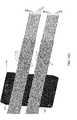
- FIG. 12illustrates a perspective view of two stacked molded plastic wheels 100 , each of which includes eight of the module housings 2 shown in FIG. 2 .
- Each wheel 100is formed as a unitary plastic molded part.
- four of the wheels 100are molded at the same time in a hot runner molding machine (not shown).
- the wheels 100are then stacked by the molding machine.
- the stacks of wheels 100are delivered to the location at which assembly of the multi-optical fiber connector module 1 shown in FIG. 1 will occur.
- an automated assembly systemhandles the wheels 100 and assembles the modules 1 without the modules 1 ever being touched by a human being. This lessens the likelihood that the modules 1 will be damaged during the assembly process.
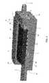
- FIG. 13illustrates a top perspective view of an assembly that includes a cleave holder 120 in accordance with an illustrative embodiment and the multi-optical fiber connector module 1 shown in FIG. 1 .
- the cleave holder 120remains secured to the fibers 4 even after the module 1 has been assembled and secured to the stripped and cleaved ends (not shown) of the fibers 4 .
- the cleave holder 120comprises a molded plastic unitary body 121 and a piece of adhesive-backed tape 122 .
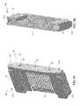
- FIG. 14Aillustrates a top perspective view of the body 121 with the piece of tape 122 removed to show grooves 123 that are formed in an upper surface 124 of the body 121 .
- FIG. 14Billustrates a bottom perspective view of the body 121 that shows four tooling reference holes 125 that are formed in a lower surface 126 of the body 121 .
- FIG. 14Cillustrates a top perspective view of the body 121 with the piece of tape 122 removed to show length-wise portions of the fibers 4 that are laid in the grooves 123 that are formed in the upper surface 124 of the body 121 .
- the body 121 of the cleave holder 120Prior to placing the fibers 4 in the grooves 123 , the body 121 of the cleave holder 120 is mounted on a stripper and cleaver tool (not shown) that has four pins (not shown) that are shaped, sized and positioned to be received in the four tooling reference holes 125 in a precision fit.
- the fibers 4are placed in the respective grooves 123 and the piece of adhesive-backed tape 122 is placed on the body 121 over the fibers 4 with a first adhesive material disposed on the back of the piece of tape 122 in contact with the body 121 , as shown in FIG. 13 .
- the piece of tape 122has cutaway areas 122 a and 122 b formed in it into which drops of a second adhesive material 127 , such as cyanoacrylate, for example, are dispensed.
- the second adhesive material 127comes into contact with the portions of the fibers 4 that are disposed in the grooves 123 and with the upper surface 124 of the body 121 of the cleave holder 120 and the lower surface of the piece of tape 122 .
- the adhesive material 127cures and becomes hardened, it fixedly secures the fibers 4 in position in between the back of the piece of tape 122 and the respective grooves 123 in which the fibers 4 are positioned.
- the tape 122 or the adhesive material 127may be sufficient for performing this function.
- some other type of mechanism or devicesuch as a cover similar to cover 3 , may instead be used for this purpose.
- the piece of tape 122essentially acts as a cover, but other types of covers or securing devices, features or elements may be used for this purpose, as will be understood by those skilled in the art in view of the description being provided herein.
- the term “cover,” as that term is used in connection with the cleave holder,is intended to denote any device, mechanism, element or material that covers the length-wise portions of the fibers 4 that are held within the grooves 123 and secures them in position on the body 121 of the cleave holder 120 .
- the fibers 4With the fibers 4 fixedly secured in position within the cleave holder 120 , and with the cleave holder body 121 mounted on the stripper and cleaver tool, the fibers 4 are stripped and the ends are cleaved with very high precision such that the length of the fibers 4 from a particular location in the cleave holder 120 to the fiber end faces 4 c ( FIG. 14C ) is equal to a very precise, predetermined value. Because stripper and cleaver tools that are suitable for this purpose are well known, an example of a stripper and cleaver tool that may be used for this purpose will not be provided herein in the interest of brevity.
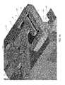
- FIGS. 15 and 16illustrate top perspective views of an assembly system 150 that is used to assemble the multi-optical fiber connector module 1 and to secure the module 1 to the fibers 4 .
- the assembly system 150includes an assembly fixture 151 on which the wheel 100 that contains the module housing 2 is mounted and on which the cleave holder 120 is mounted.
- An automated arm 152 of the assembly system 150maneuvers the wheel 100 relative to the assembly fixture 151 until a portion 154 of the wheel 100 just below a selected one of the module housings 2 engages the assembly fixture 151 . When this portion 154 of the wheel 100 is engaged with the assembly fixture 151 , the selected module housing 2 is at a precise position and orientation on the assembly fixture 151 .
- the assembly fixture 151also includes four pins (not shown) that are positioned, shaped and sized to be received in the four tooling reference holes 125 formed in the lower surface of the cleave holder body 121 .
- the fibers 4are precisely positioned in the respective V-shaped grooves 6 ( FIG. 2 ) and the respective end faces 4 c are precisely located in the module housing 2 .
- the cover 3( FIG. 16 ) is placed in the cavity 5 of the module housing 2 by a person using a finger or a tool, such as a pair of tweezers, for example.
- the process of placing the cover 3 in the cavity 5could also be performed automatically by the system 150 .
- a spring finger 157 of the system 150gently holds the cover 3 in position as the adhesive material 7 is placed in the gap 8 , as shown in FIG. 16 .
- the adhesive material 7cures and becomes hardened, it locks the cover 3 and the fibers 4 in place on the module housing 2 .
- a toolmay then be used to cut through the portion 154 of the wheel 100 in order to separate the wheel 100 from the module housing 2 .
- the assemblythat includes the module 1 , the cleave holder 120 and the portions of the fibers 4 that are attached to the module 1 and to the cleave holder 120 may then be removed from the assembly fixture 151 of the assembly system 150 .
- both the cleave holder 120 and the module 1will typically remain attached to the fibers 4 in the configuration shown in FIG. 13 .
- the cleave holder 120may be mounted on a housing (not shown) by mating the holes 125 ( FIG. 14B ) of the cleave holder body 121 with respective pins (not shown) that are disposed on the housing.
- the cleave holder 120can act as a strain relief mechanism by preventing forces that are exerted on the portions 4 d ( FIG. 13 ) of the fibers 4 from being exerted on portions 4 e ( FIG. 13 ) of the fibers 4 that extend in between the cleave holder 120 and the module 1 .
- the cleave holder 120is not limited to being used with the module 1 or with any other module. After the fibers 4 have been stripped and cleaved, the cleave holder 120 may remain attached to the fibers 4 and used for some purpose even if the end faces of the fibers 4 are not secured to a module. For example, if the end faces of the fibers 4 are to be mechanically and optically interfaced with a piece of equipment that does need include a connector module, the cleave holder 20 may be mounted on pins disposed on a housing or chassis of the equipment to ensure that the end faces of the fibers are at a predetermined, precise distance from the cleave holder 20 . In such cases, the cleave holder 120 would also perform strain relief functions.
- the inventionhas been described with reference to illustrative, or exemplary, embodiments in order to demonstrate the principles and concepts of the invention.
- the inventionis not limited to the illustrative embodiments described herein.
- the cleave holder 120is not limited to having the shape shown in the figures and is not limited to being used with the connector module 1 .
- Persons skilled in the artwill understand, in view of the description provided herein, that a variety of modifications can be made to the embodiments described herein and that all such modifications are within the scope of the invention.
Landscapes
- Physics & Mathematics (AREA)
- General Physics & Mathematics (AREA)
- Optics & Photonics (AREA)
- Mechanical Coupling Of Light Guides (AREA)
Abstract
Description
Claims (20)
Priority Applications (2)
| Application Number | Priority Date | Filing Date | Title |
|---|---|---|---|
| US13/621,588US9002168B2 (en) | 2012-09-17 | 2012-09-17 | Cleave holder, an assembly, and methods for cleaving ends of optical fibers and securing them to a multi-optical fiber connector module |
| TW102130681ATW201415109A (en) | 2012-09-17 | 2013-08-27 | A cleave holder, an assembly, and methods for cleaving ends of optical fibers and securing them to a multi-optical fiber connector module |
Applications Claiming Priority (1)
| Application Number | Priority Date | Filing Date | Title |
|---|---|---|---|
| US13/621,588US9002168B2 (en) | 2012-09-17 | 2012-09-17 | Cleave holder, an assembly, and methods for cleaving ends of optical fibers and securing them to a multi-optical fiber connector module |
Publications (2)
| Publication Number | Publication Date |
|---|---|
| US20140079357A1 US20140079357A1 (en) | 2014-03-20 |
| US9002168B2true US9002168B2 (en) | 2015-04-07 |
Family
ID=50274557
Family Applications (1)
| Application Number | Title | Priority Date | Filing Date |
|---|---|---|---|
| US13/621,588Active2032-10-19US9002168B2 (en) | 2012-09-17 | 2012-09-17 | Cleave holder, an assembly, and methods for cleaving ends of optical fibers and securing them to a multi-optical fiber connector module |
Country Status (2)
| Country | Link |
|---|---|
| US (1) | US9002168B2 (en) |
| TW (1) | TW201415109A (en) |
Cited By (2)
| Publication number | Priority date | Publication date | Assignee | Title |
|---|---|---|---|---|
| JP2017156617A (en)* | 2016-03-03 | 2017-09-07 | 住友電気工業株式会社 | Optical connection member, optical connector, and optical fiber with connector |
| US20230152531A1 (en)* | 2015-10-12 | 2023-05-18 | 3M Innovative Properties Company | Optical waveguide positioning feature in a multiple waveguides connector |
Families Citing this family (6)
| Publication number | Priority date | Publication date | Assignee | Title |
|---|---|---|---|---|
| US9529152B2 (en)* | 2014-10-31 | 2016-12-27 | Corning Optical Communications LLC | Laser cleaving multi-row ribbon fibers |
| US10345542B2 (en)* | 2016-06-28 | 2019-07-09 | Mellanox Technologies, Ltd. | Opto-mechanical coupler |
| US10088639B2 (en) | 2016-06-28 | 2018-10-02 | Mellanox Technologies, Ltd. | Opto-mechanical coupler |
| US11340404B2 (en)* | 2019-10-10 | 2022-05-24 | Senko Advanced Components, Inc. | Fiber array assembly using a fixing material for securing fiber optic bundles therein |
| CN114196932B (en)* | 2020-09-18 | 2023-07-21 | 潍坊华光光电子有限公司 | Optical fiber coating clamp and use method |
| CN119439394B (en)* | 2024-12-20 | 2025-07-08 | 中山市美速光电技术有限公司 | Multi-channel MCF optical fiber connection structure based on data transmission and manufacturing method thereof |
Citations (39)
| Publication number | Priority date | Publication date | Assignee | Title |
|---|---|---|---|---|
| US5216741A (en)* | 1991-03-08 | 1993-06-01 | Koninklijke Ptt Nederland N.V. | Method of positioning and fixing optical fibres in a row of optical fibres and a coupling device provided with such a row of fibres |
| US5501385A (en)* | 1994-12-08 | 1996-03-26 | The United States Of America As Represented By The United States Department Of Energy | Large core fiber optic cleaver |
| US5892870A (en) | 1995-11-16 | 1999-04-06 | Fiber Connections Inc. | Fibre optic cable connector |
| US5907651A (en) | 1997-07-28 | 1999-05-25 | Molex Incorporated | Fiber optic connector ferrule |
| US5909528A (en)* | 1995-10-31 | 1999-06-01 | Sumitomo Electric Industries, Ltd. | Optical connector and assembly method thereof |
| US5923803A (en)* | 1997-07-28 | 1999-07-13 | Molex Incorporated | Method of fabricating a fiber optic connector ferrule |
| US5946986A (en)* | 1997-10-23 | 1999-09-07 | Amherst International, Inc. | Optical fiber preparation unit |
| US6085003A (en) | 1998-07-28 | 2000-07-04 | Us Conec Ltd | Multifiber connector having a free floating ferrule |
| US6585421B1 (en)* | 2000-09-15 | 2003-07-01 | Corning Cable Systems Llc | Spacer and strain relief for fiber optic connectors |
| US20030123836A1 (en)* | 2001-12-27 | 2003-07-03 | Fujikura Ltd. | Optical fiber holder, optical fiber adapter, and optical fiber processing device having a positioning mechanism |
| US6594436B2 (en) | 2001-07-23 | 2003-07-15 | Molex Incorporated | Holding assembly for cross-connected optical fibers between plural fiber ribbons |
| US20040071407A1 (en)* | 2000-10-25 | 2004-04-15 | Henricus Vergeest | Optical ferrule-less connector |
| US6722791B2 (en)* | 2002-04-19 | 2004-04-20 | Hon Hai Precision Ind. Co., Ltd. | Multi-fiber ferrule |
| US6860645B2 (en) | 2003-06-26 | 2005-03-01 | Furukawa Electric North America, Inc. | Optical fiber cable connector assembly with strain relief |
| US20050058422A1 (en)* | 2002-09-19 | 2005-03-17 | 3M Innovative Properties Company | Article for cleaving and polishing optical fiber ends |
| US6918703B2 (en) | 2002-06-12 | 2005-07-19 | Molex Incorporated | System for terminating optical fibers in a fiber optic connector |
| US6931195B2 (en) | 2003-08-05 | 2005-08-16 | Agilent Technologies, Inc. | Parallel fiber-fan-out optical interconnect for fiber optic system |
| JP2006010871A (en) | 2004-06-23 | 2006-01-12 | Sumitomo Electric Ind Ltd | Optical fiber connector |
| US7003869B2 (en) | 2000-05-05 | 2006-02-28 | Hubbell Incorporated | Crimp tool for strain relief connector and method of forming a strain relief connector |
| US7197224B2 (en) | 2003-07-24 | 2007-03-27 | Reflex Photonics Inc. | Optical ferrule |
| US7220065B2 (en) | 2003-12-24 | 2007-05-22 | Electronics And Telecommunications Research Institute | Connection apparatus for parallel optical interconnect module and parallel optical interconnect module using the same |
| US7280733B2 (en) | 2005-10-24 | 2007-10-09 | 3M Innovative Properties Company | Fiber termination platform for optical connectors |
| US20080095502A1 (en)* | 2006-10-19 | 2008-04-24 | Mccolloch Laurence Ray | Stackable multi-optical fiber connector modules and devices for aligning sets of the stackable multi-optical fiber connector modules and coupling optical signals between them |
| US20080095506A1 (en)* | 2006-10-19 | 2008-04-24 | Mccolloch Laurence Ray | multi-optical fiber connector module for use with a transceiver module and method for coupling optical signals between the transceiver module and multiple optical fibers |
| US20090124117A1 (en)* | 2006-05-08 | 2009-05-14 | Ralf Schleith | Plug connector |
| US20090154884A1 (en)* | 2005-04-04 | 2009-06-18 | Wenzong Chen | Multifiber MT-Type Connector and Ferrule Comprising V-Groove Lens Array and Method of Manufacture |
| US7553091B2 (en) | 2006-10-19 | 2009-06-30 | Avago Technologies Fiber Ip (Singapore) Pte. Ltd. | Stackable multi-optical fiber connector modules and devices for aligning sets of the stackable multi-optical fiber connector modules and coupling optical signals between them |
| US7567743B1 (en)* | 2008-04-02 | 2009-07-28 | Tyco Electronics Corporation | Field terminating method and device |
| US20100202735A1 (en)* | 2008-12-19 | 2010-08-12 | Childers Darrell R | Field Install Fiber Clip and Method of Use |
| US20100220953A1 (en) | 2008-08-21 | 2010-09-02 | Telescent Inc. | Braided Fiber Optic Cross-Connect Switches |
| US7794156B2 (en) | 2007-08-28 | 2010-09-14 | Emcore Corporation | Internal EMI washer for optical transceiver with parallel optic fiber ribbon |
| US20110044590A1 (en)* | 2007-04-13 | 2011-02-24 | Adc Telecommunications, Inc. | Field terminatable fiber optic connector assembly |
| US7905751B1 (en) | 2009-09-23 | 2011-03-15 | Tyco Electronics Corporation | Electrical connector module with contacts of a differential pair held in separate chicklets |
| CN201796164U (en) | 2010-09-21 | 2011-04-13 | 南京华脉科技有限公司 | Cold splice connector of optical fiber |
| US8002477B2 (en) | 2002-12-17 | 2011-08-23 | International Business Machines Corporation | Devices and methods for side-coupling optical fibers to optoelectronic components |
| US8036500B2 (en) | 2009-05-29 | 2011-10-11 | Avago Technologies Fiber Ip (Singapore) Pte. Ltd | Mid-plane mounted optical communications system and method for providing high-density mid-plane mounting of parallel optical communications modules |
| US20120145307A1 (en)* | 2009-08-21 | 2012-06-14 | Optogig, Inc. | Method of mt ferrule termination and protrusion equalization fixture |
| US20120213475A1 (en)* | 2009-11-03 | 2012-08-23 | Selli Raman K | Fiber optic devices and methods of manufacturing fiber optic devices |
| US8414200B2 (en)* | 2003-11-04 | 2013-04-09 | Tyco Electronics Raychem Nv | Device for installing an optical fibre in a splice connector |
- 2012
- 2012-09-17USUS13/621,588patent/US9002168B2/enactiveActive
- 2013
- 2013-08-27TWTW102130681Apatent/TW201415109A/enunknown
Patent Citations (40)
| Publication number | Priority date | Publication date | Assignee | Title |
|---|---|---|---|---|
| US5216741A (en)* | 1991-03-08 | 1993-06-01 | Koninklijke Ptt Nederland N.V. | Method of positioning and fixing optical fibres in a row of optical fibres and a coupling device provided with such a row of fibres |
| US5501385A (en)* | 1994-12-08 | 1996-03-26 | The United States Of America As Represented By The United States Department Of Energy | Large core fiber optic cleaver |
| US5909528A (en)* | 1995-10-31 | 1999-06-01 | Sumitomo Electric Industries, Ltd. | Optical connector and assembly method thereof |
| US5892870A (en) | 1995-11-16 | 1999-04-06 | Fiber Connections Inc. | Fibre optic cable connector |
| US5907651A (en) | 1997-07-28 | 1999-05-25 | Molex Incorporated | Fiber optic connector ferrule |
| US5923803A (en)* | 1997-07-28 | 1999-07-13 | Molex Incorporated | Method of fabricating a fiber optic connector ferrule |
| US5946986A (en)* | 1997-10-23 | 1999-09-07 | Amherst International, Inc. | Optical fiber preparation unit |
| US6085003A (en) | 1998-07-28 | 2000-07-04 | Us Conec Ltd | Multifiber connector having a free floating ferrule |
| US7003869B2 (en) | 2000-05-05 | 2006-02-28 | Hubbell Incorporated | Crimp tool for strain relief connector and method of forming a strain relief connector |
| US6585421B1 (en)* | 2000-09-15 | 2003-07-01 | Corning Cable Systems Llc | Spacer and strain relief for fiber optic connectors |
| US20040071407A1 (en)* | 2000-10-25 | 2004-04-15 | Henricus Vergeest | Optical ferrule-less connector |
| US6594436B2 (en) | 2001-07-23 | 2003-07-15 | Molex Incorporated | Holding assembly for cross-connected optical fibers between plural fiber ribbons |
| US20030123836A1 (en)* | 2001-12-27 | 2003-07-03 | Fujikura Ltd. | Optical fiber holder, optical fiber adapter, and optical fiber processing device having a positioning mechanism |
| US6722791B2 (en)* | 2002-04-19 | 2004-04-20 | Hon Hai Precision Ind. Co., Ltd. | Multi-fiber ferrule |
| US6918703B2 (en) | 2002-06-12 | 2005-07-19 | Molex Incorporated | System for terminating optical fibers in a fiber optic connector |
| US20050058422A1 (en)* | 2002-09-19 | 2005-03-17 | 3M Innovative Properties Company | Article for cleaving and polishing optical fiber ends |
| US8002477B2 (en) | 2002-12-17 | 2011-08-23 | International Business Machines Corporation | Devices and methods for side-coupling optical fibers to optoelectronic components |
| US6860645B2 (en) | 2003-06-26 | 2005-03-01 | Furukawa Electric North America, Inc. | Optical fiber cable connector assembly with strain relief |
| US7197224B2 (en) | 2003-07-24 | 2007-03-27 | Reflex Photonics Inc. | Optical ferrule |
| US6931195B2 (en) | 2003-08-05 | 2005-08-16 | Agilent Technologies, Inc. | Parallel fiber-fan-out optical interconnect for fiber optic system |
| US8414200B2 (en)* | 2003-11-04 | 2013-04-09 | Tyco Electronics Raychem Nv | Device for installing an optical fibre in a splice connector |
| US7220065B2 (en) | 2003-12-24 | 2007-05-22 | Electronics And Telecommunications Research Institute | Connection apparatus for parallel optical interconnect module and parallel optical interconnect module using the same |
| JP2006010871A (en) | 2004-06-23 | 2006-01-12 | Sumitomo Electric Ind Ltd | Optical fiber connector |
| US20090154884A1 (en)* | 2005-04-04 | 2009-06-18 | Wenzong Chen | Multifiber MT-Type Connector and Ferrule Comprising V-Groove Lens Array and Method of Manufacture |
| US7280733B2 (en) | 2005-10-24 | 2007-10-09 | 3M Innovative Properties Company | Fiber termination platform for optical connectors |
| US20090124117A1 (en)* | 2006-05-08 | 2009-05-14 | Ralf Schleith | Plug connector |
| US20080095506A1 (en)* | 2006-10-19 | 2008-04-24 | Mccolloch Laurence Ray | multi-optical fiber connector module for use with a transceiver module and method for coupling optical signals between the transceiver module and multiple optical fibers |
| US7543994B2 (en) | 2006-10-19 | 2009-06-09 | Avago Technologies Fiber Ip (Singapore) Pte. Ltd. | Multi-optical fiber connector module for use with a transceiver module and method for coupling optical signals between the transceiver module and multiple optical fibers |
| US7553091B2 (en) | 2006-10-19 | 2009-06-30 | Avago Technologies Fiber Ip (Singapore) Pte. Ltd. | Stackable multi-optical fiber connector modules and devices for aligning sets of the stackable multi-optical fiber connector modules and coupling optical signals between them |
| US20080095502A1 (en)* | 2006-10-19 | 2008-04-24 | Mccolloch Laurence Ray | Stackable multi-optical fiber connector modules and devices for aligning sets of the stackable multi-optical fiber connector modules and coupling optical signals between them |
| US20110044590A1 (en)* | 2007-04-13 | 2011-02-24 | Adc Telecommunications, Inc. | Field terminatable fiber optic connector assembly |
| US7794156B2 (en) | 2007-08-28 | 2010-09-14 | Emcore Corporation | Internal EMI washer for optical transceiver with parallel optic fiber ribbon |
| US7567743B1 (en)* | 2008-04-02 | 2009-07-28 | Tyco Electronics Corporation | Field terminating method and device |
| US20100220953A1 (en) | 2008-08-21 | 2010-09-02 | Telescent Inc. | Braided Fiber Optic Cross-Connect Switches |
| US20100202735A1 (en)* | 2008-12-19 | 2010-08-12 | Childers Darrell R | Field Install Fiber Clip and Method of Use |
| US8036500B2 (en) | 2009-05-29 | 2011-10-11 | Avago Technologies Fiber Ip (Singapore) Pte. Ltd | Mid-plane mounted optical communications system and method for providing high-density mid-plane mounting of parallel optical communications modules |
| US20120145307A1 (en)* | 2009-08-21 | 2012-06-14 | Optogig, Inc. | Method of mt ferrule termination and protrusion equalization fixture |
| US7905751B1 (en) | 2009-09-23 | 2011-03-15 | Tyco Electronics Corporation | Electrical connector module with contacts of a differential pair held in separate chicklets |
| US20120213475A1 (en)* | 2009-11-03 | 2012-08-23 | Selli Raman K | Fiber optic devices and methods of manufacturing fiber optic devices |
| CN201796164U (en) | 2010-09-21 | 2011-04-13 | 南京华脉科技有限公司 | Cold splice connector of optical fiber |
Non-Patent Citations (2)
| Title |
|---|
| MTP Backplane Interconnect System (BMTP), p. 1, Molex. |
| MTP Solutions for High Density Networks, 2010, p. 1-22, FireFab, United Kingdom. |
Cited By (4)
| Publication number | Priority date | Publication date | Assignee | Title |
|---|---|---|---|---|
| US20230152531A1 (en)* | 2015-10-12 | 2023-05-18 | 3M Innovative Properties Company | Optical waveguide positioning feature in a multiple waveguides connector |
| US11906789B2 (en)* | 2015-10-12 | 2024-02-20 | 3M Innovative Properties Company | Optical waveguide positioning feature in a multiple waveguides connector |
| JP2017156617A (en)* | 2016-03-03 | 2017-09-07 | 住友電気工業株式会社 | Optical connection member, optical connector, and optical fiber with connector |
| US10481346B2 (en) | 2016-03-03 | 2019-11-19 | Sumitomo Electric Industries, Ltd. | Optical connection member, optical connector, and optical fiber having connector |
Also Published As
| Publication number | Publication date |
|---|---|
| TW201415109A (en) | 2014-04-16 |
| US20140079357A1 (en) | 2014-03-20 |
Similar Documents
| Publication | Publication Date | Title |
|---|---|---|
| US9002168B2 (en) | Cleave holder, an assembly, and methods for cleaving ends of optical fibers and securing them to a multi-optical fiber connector module | |
| US8801297B2 (en) | Methods and systems for blind mating multi-optical fiber connector modules | |
| US11353663B2 (en) | Unitary multi-fiber optical ferrule with integrated lenses | |
| US10684431B2 (en) | Fiber optic connector assembly, apparatus for forming a transceiver interface, and ferrule | |
| EP1861739B1 (en) | Multi-fiber fiber optic receptacle and plug assembly | |
| US9690053B2 (en) | Multifiber connectorization techniques for multicore optical fiber cables | |
| US20100215319A1 (en) | Multi-Fiber Ferrule with Integrated, Molded Guide Pin | |
| US20140147078A1 (en) | Gradient index (grin) lens chips and associated small form factor optical arrays for optical connections, related fiber optic connectors | |
| US9465170B1 (en) | Unitary multi-fiber optical ferrule with integrated lenses | |
| US20070160327A1 (en) | Multi-fiber fiber optic receptacle and plug assembly | |
| CN108139547A (en) | Optical waveguide locating feature in more waveguide connectors | |
| US9086547B2 (en) | Multi-optical fiber connector module having a cover comprising unfilled plastic having deformable features formed therein, and a method | |
| US20140143996A1 (en) | Methods of forming gradient index (grin) lens chips for optical connections and related fiber optic connectors | |
| US9140862B2 (en) | Methods, apparatuses and systems for blind mating multi-optical fiber connector modules | |
| WO2007015983A2 (en) | Multi-fiber fiber optic assembly | |
| CN104335091A (en) | Simplified fiber optic connector with optics and method for manufacturing same | |
| US20170184800A1 (en) | Ferrule for multi-fiber optical connector | |
| US20110110630A1 (en) | Optical transmission medium, ferrule, optical terminal connector, optical structure, and optical equipment | |
| US6931195B2 (en) | Parallel fiber-fan-out optical interconnect for fiber optic system | |
| WO2020081439A1 (en) | Ferrules including keying features and fiber optic junctions including the same | |
| US20170052321A1 (en) | Fused expanded beam connector | |
| EP1596231B1 (en) | Optical transmission medium connecting method and optical connecting structure | |
| WO2022232508A1 (en) | Pitch conversion ferrule boot |
Legal Events
| Date | Code | Title | Description |
|---|---|---|---|
| AS | Assignment | Owner name:AVAGO TECHNOLOGIES FIBER IP (SINGAPORE) PTE. LTD., Free format text:ASSIGNMENT OF ASSIGNORS INTEREST;ASSIGNOR:MCCOLLOCH, LAURENCE R.;REEL/FRAME:029101/0770 Effective date:20120917 | |
| AS | Assignment | Owner name:AVAGO TECHNOLOGIES GENERAL IP (SINGAPORE) PTE. LTD Free format text:MERGER;ASSIGNOR:AVAGO TECHNOLOGIES FIBER IP (SINGAPORE) PTE. LTD.;REEL/FRAME:030695/0244 Effective date:20121030 | |
| AS | Assignment | Owner name:AVAGO TECHNOLOGIES GENERAL IP (SINGAPORE) PTE. LTD Free format text:CORRECTIVE ASSIGNMENT TO CORRECT THE ASSIGNEE NAME PREVIOUSLY RECORDED ON REEL 029101 FRAME 0770. ASSIGNOR(S) HEREBY CONFIRMS THE CORRECT ASSIGNEE NAME IS AVAGO TECHNOLOGIES GENERAL IP (SINGAPORE) PTE. LTD.;ASSIGNOR:MCCOLLOCH, LAURENCE R.;REEL/FRAME:030812/0382 Effective date:20120917 | |
| AS | Assignment | Owner name:DEUTSCHE BANK AG NEW YORK BRANCH, AS COLLATERAL AGENT, NEW YORK Free format text:PATENT SECURITY AGREEMENT;ASSIGNOR:AVAGO TECHNOLOGIES GENERAL IP (SINGAPORE) PTE. LTD.;REEL/FRAME:032851/0001 Effective date:20140506 Owner name:DEUTSCHE BANK AG NEW YORK BRANCH, AS COLLATERAL AG Free format text:PATENT SECURITY AGREEMENT;ASSIGNOR:AVAGO TECHNOLOGIES GENERAL IP (SINGAPORE) PTE. LTD.;REEL/FRAME:032851/0001 Effective date:20140506 | |
| STCF | Information on status: patent grant | Free format text:PATENTED CASE | |
| AS | Assignment | Owner name:AVAGO TECHNOLOGIES GENERAL IP (SINGAPORE) PTE. LTD., SINGAPORE Free format text:TERMINATION AND RELEASE OF SECURITY INTEREST IN PATENT RIGHTS (RELEASES RF 032851-0001);ASSIGNOR:DEUTSCHE BANK AG NEW YORK BRANCH, AS COLLATERAL AGENT;REEL/FRAME:037689/0001 Effective date:20160201 Owner name:AVAGO TECHNOLOGIES GENERAL IP (SINGAPORE) PTE. LTD Free format text:TERMINATION AND RELEASE OF SECURITY INTEREST IN PATENT RIGHTS (RELEASES RF 032851-0001);ASSIGNOR:DEUTSCHE BANK AG NEW YORK BRANCH, AS COLLATERAL AGENT;REEL/FRAME:037689/0001 Effective date:20160201 | |
| AS | Assignment | Owner name:BANK OF AMERICA, N.A., AS COLLATERAL AGENT, NORTH CAROLINA Free format text:PATENT SECURITY AGREEMENT;ASSIGNOR:AVAGO TECHNOLOGIES GENERAL IP (SINGAPORE) PTE. LTD.;REEL/FRAME:037808/0001 Effective date:20160201 Owner name:BANK OF AMERICA, N.A., AS COLLATERAL AGENT, NORTH Free format text:PATENT SECURITY AGREEMENT;ASSIGNOR:AVAGO TECHNOLOGIES GENERAL IP (SINGAPORE) PTE. LTD.;REEL/FRAME:037808/0001 Effective date:20160201 | |
| AS | Assignment | Owner name:AVAGO TECHNOLOGIES GENERAL IP (SINGAPORE) PTE. LTD., SINGAPORE Free format text:TERMINATION AND RELEASE OF SECURITY INTEREST IN PATENTS;ASSIGNOR:BANK OF AMERICA, N.A., AS COLLATERAL AGENT;REEL/FRAME:041710/0001 Effective date:20170119 Owner name:AVAGO TECHNOLOGIES GENERAL IP (SINGAPORE) PTE. LTD Free format text:TERMINATION AND RELEASE OF SECURITY INTEREST IN PATENTS;ASSIGNOR:BANK OF AMERICA, N.A., AS COLLATERAL AGENT;REEL/FRAME:041710/0001 Effective date:20170119 | |
| MAFP | Maintenance fee payment | Free format text:PAYMENT OF MAINTENANCE FEE, 4TH YEAR, LARGE ENTITY (ORIGINAL EVENT CODE: M1551); ENTITY STATUS OF PATENT OWNER: LARGE ENTITY Year of fee payment:4 | |
| AS | Assignment | Owner name:AVAGO TECHNOLOGIES INTERNATIONAL SALES PTE. LIMITE Free format text:MERGER;ASSIGNOR:AVAGO TECHNOLOGIES GENERAL IP (SINGAPORE) PTE. LTD.;REEL/FRAME:047422/0464 Effective date:20180509 | |
| AS | Assignment | Owner name:AVAGO TECHNOLOGIES INTERNATIONAL SALES PTE. LIMITE Free format text:CORRECTIVE ASSIGNMENT TO CORRECT THE EXECUTION DATE PREVIOUSLY RECORDED AT REEL: 047422 FRAME: 0464. ASSIGNOR(S) HEREBY CONFIRMS THE MERGER;ASSIGNOR:AVAGO TECHNOLOGIES GENERAL IP (SINGAPORE) PTE. LTD.;REEL/FRAME:048883/0702 Effective date:20180905 | |
| AS | Assignment | Owner name:BROADCOM INTERNATIONAL PTE. LTD., SINGAPORE Free format text:ASSIGNMENT OF ASSIGNORS INTEREST;ASSIGNOR:AVAGO TECHNOLOGIES INTERNATIONAL SALES PTE. LIMITED;REEL/FRAME:053771/0901 Effective date:20200826 | |
| MAFP | Maintenance fee payment | Free format text:PAYMENT OF MAINTENANCE FEE, 8TH YEAR, LARGE ENTITY (ORIGINAL EVENT CODE: M1552); ENTITY STATUS OF PATENT OWNER: LARGE ENTITY Year of fee payment:8 | |
| AS | Assignment | Owner name:AVAGO TECHNOLOGIES INTERNATIONAL SALES PTE. LIMITED, SINGAPORE Free format text:MERGER;ASSIGNORS:AVAGO TECHNOLOGIES INTERNATIONAL SALES PTE. LIMITED;BROADCOM INTERNATIONAL PTE. LTD.;REEL/FRAME:062952/0850 Effective date:20230202 |