US9001594B2 - Apparatuses and methods for adjusting a path delay of a command path - Google Patents
Apparatuses and methods for adjusting a path delay of a command pathDownload PDFInfo
- Publication number
- US9001594B2 US9001594B2US13/543,698US201213543698AUS9001594B2US 9001594 B2US9001594 B2US 9001594B2US 201213543698 AUS201213543698 AUS 201213543698AUS 9001594 B2US9001594 B2US 9001594B2
- Authority
- US
- United States
- Prior art keywords
- command
- delay
- path
- signal
- clock
- Prior art date
- Legal status (The legal status is an assumption and is not a legal conclusion. Google has not performed a legal analysis and makes no representation as to the accuracy of the status listed.)
- Active, expires
Links
Images


Classifications
- G—PHYSICS
- G11—INFORMATION STORAGE
- G11C—STATIC STORES
- G11C7/00—Arrangements for writing information into, or reading information out from, a digital store
- G11C7/10—Input/output [I/O] data interface arrangements, e.g. I/O data control circuits, I/O data buffers
- G11C7/1078—Data input circuits, e.g. write amplifiers, data input buffers, data input registers, data input level conversion circuits
- G11C7/109—Control signal input circuits
- G—PHYSICS
- G11—INFORMATION STORAGE
- G11C—STATIC STORES
- G11C7/00—Arrangements for writing information into, or reading information out from, a digital store
- G11C7/10—Input/output [I/O] data interface arrangements, e.g. I/O data control circuits, I/O data buffers
- G11C7/1078—Data input circuits, e.g. write amplifiers, data input buffers, data input registers, data input level conversion circuits
- G11C7/1093—Input synchronization
- G—PHYSICS
- G11—INFORMATION STORAGE
- G11C—STATIC STORES
- G11C7/00—Arrangements for writing information into, or reading information out from, a digital store
- G11C7/22—Read-write [R-W] timing or clocking circuits; Read-write [R-W] control signal generators or management
- G11C7/222—Clock generating, synchronizing or distributing circuits within memory device
- G—PHYSICS
- G11—INFORMATION STORAGE
- G11C—STATIC STORES
- G11C2207/00—Indexing scheme relating to arrangements for writing information into, or reading information out from, a digital store
- G11C2207/22—Control and timing of internal memory operations
- G11C2207/2254—Calibration
Definitions
- Embodiments of the inventionrelate generally to semiconductor memory, and more specifically, in one or more described embodiment, to timing internal clock, data, and command signals for executing memory commands in a memory.
- proper operation of the memoryis based on the correct timing of various internal command, data, and clock signals. For example, in writing data to memory internal clock signals that clock data path circuitry to latch write data may need to be provided with specific timing relationships with internal write command signals to properly enable the data path circuitry to provide the latched write data for writing to memory. If the timing of the internal write command signal is not such that the data path circuitry is enabled at the time the internal clock signal clocks the data path circuitry to provide the write data at an expected time, the write command may be inadvertently ignored or the write data provided to the memory may not be correct (e.g., the write data is associated with another read command).
- various latenciesmay be programmed to set a time, typically in number of clock periods tCK, between receipt of a write command by the memory and when the write data is provided to the memory.
- the latencymay be programmed by a user of the memory to accommodate clock signals of different frequencies (i.e., different clock periods).
- Internal clock, data, and write command pathsshould be designed to provide propagation delays for the respective signals to account for the latency, for example, the latencies between receipt of a write command and receipt of the write data for the write command.
- commandsthat may require the correct timing of internal clock, data, and command signals for proper operation include, for example, read commands and on-die termination enable commands.
- Complicating the generation of correctly timed internal clock, data, and command signalsis the relatively high-frequency of memory clock signals.
- memory clock signalscan exceed 1 GHz.
- multi-data rate memoriesmay receive data at a rate higher than the memory clock signal.
- An example of a multi-data rate memoryis one that receives write data at a rate twice that of the clock frequency, such as receiving write data synchronized with rising and falling clock edges of the memory clock signal.
- the frequency of the memory clock signalmay be the frequency at which write commands are executed.
- the timing domains of command and clock signalsmay need to be crossed in order to maintain proper timing of the internal clock, data, and command signals.
- An example conventional approach to maintaining the timing of internal write command, data, and clock signalsis modeling both the data path and the write command path to have the same propagation delay.
- a data pathwhich typically has a shorter inherent path delay than the write path, may include delay circuits to provide a total path delay that matches that of the write path. This may require, however, that delays and/or counter circuitry run continuously during memory operation.
- delay circuits in the data pathare replicated for every bit of the data path, thus a wider data path results in a corresponding increase in delay circuits. As a result, power consumption may be higher than desirable.
- the propagation delay of the various internal clock, data, and command pathscan often vary due to changes in power, voltage, and temperature conditions. For clock, data and command paths having relatively long propagation delay or additional delay circuitry, the variations due to changing operating conditions may negatively affect the timing of the internal signals to such a degree that the memory does not operate properly.
- FIG. 1is a block diagram of an apparatus including a command path according to an embodiment of the invention.
- FIG. 2is a timing diagram of various signals during operation of command and data paths according to an embodiment of the invention.
- FIG. 3is a block diagram of a command path delay circuit according to an embodiment of the invention.
- FIG. 4is a block diagram of a path delay measurement circuit that may be used in an embodiment of the invention.
- FIG. 5is a block diagram of a memory including a command path according to an embodiment of the invention.
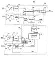
- FIG. 1illustrates an apparatus 100 including a command path 130 according to an embodiment of the invention.
- FIG. 1further illustrates clock paths 110 and 120 , and data path 160 .
- the clock path 110 and clock path 120are configured to provide clock signals that may be used to clock circuits during operation of the command path 130 and the data path 160 .
- FIG. 1will be specifically described with reference to write commands and write data, other embodiments may include other examples of commands and data.
- the term “provide” (and forms thereof)shall be broadly construed to include, for example, generate, output, apply, etc., and is intended to generally cover other such acts.
- the clock path 110includes a clock receiver 112 configured to receive a clock signal XClk and provide an output clock signal GClk to a clock buffer 114 .
- the clock receiver 112may drive the signal levels of the XClk signal to full clock signal voltages before providing the resulting GClk signal to the clock buffer 114 .
- the clock buffer 114may be configured to buffer the GClk signal and provide a Clk signal to the command path 130 .
- the GClk signalis also provided to the command path 130 .
- the buffer 114may also further delay the GClk signal before being output as the Clk signal for the purpose of matching propagation delay of circuitry in the command path 130 .
- GClk and Clk signalsmay have respective phases that are different than that of the XClk signal.
- the clock path 120includes a clock receiver 122 configured to receive the write clock signal XDQS and provide an output clock signal DQS to clock routing 124 .
- the clock receiver 122may drive the signal levels of the XDQS signal to full clock signal voltages before providing the resulting DQS signal to clock routing 124 .
- Clock routing 124may represent clock signal routing that is used to provide the DQS signal throughout a memory to be used by other circuitry.
- DQS signalmay be routed by clock routing 124 to be provided as DQ strobe signal DQST to circuitry of the data path 160 for use in capturing write data, as will be described in more detail below.
- the clock routing 124also provides the DQS signal as a GDQSD signal to confirmation logic 126 .
- the confirmation logic 126generates a DQ clock signal DQClk responsive to the GDQSD signal and a write data command signal WrDinD, which is provided by the command path 130 .
- the confirmation logicconfirms that an internal write command (represented by the WrDinD signal) is active for a portion of the DQS signal and provides the DQClk signal to clock output write data from the data path 160 , as will be described in more detail below.
- the data path 160includes a data receiver 162 configured to receive write data XDQ and provide write data DQ to data tree 164 .
- the data tree 164is configured to provide (e.g., distribute) the DQ write data as Dx write data to data capture latches 166 .
- the data capture latches 166latch the Dx write data responsive to clock edges of the DQST signal from the clock path 120 , and provide the latched data as DxRF and DxFF write data to a data shift circuit 168 .
- the DxRF write datais provided responsive to a rising edge of the DQST signal and the DxFF write data is provided responsive to a falling edge of the DQST signal.
- the data capture latches 166latch the Dx write data and provide it as DxRF write data responsive to clock edges of the DQST signal (e.g., rising clock edges) to the data shift circuit 168 .
- the data capture latches 166latch the Dx write data and provide it as DxFF write data responsive to clock edges of the DQST signal (e.g., falling clock edges) to the data shift circuit 168 .
- the data shift circuit 168provides the DxRF, DxFF write data as DW write data responsive to the DQClk signal from the clock path 120 .
- the operation by the data capture latches 166 and the data shift circuit 168 responsive to the DQST and DQClkprovide a serial-to-parallel write data operation.
- the write data Dxmay be latched (e.g., in parallel) at twice the frequency of the XDQS signal and provided as serial write data DW at a lower frequency of the XDQS signal, which has the same clock frequency as the XClk signal.
- the XDQ write datais provided to the data receiver 162 center-aligned with clock edges of the XDQS signal.
- the propagation delay through the data receiver 162 and the data tree 164is approximately the same as the propagation delay through the clock receiver 122 and the clock routing 124 of clock path 120 .
- the Dx write data provided by the data tree 164remains substantially center-aligned with edges of the DQST signal provided by the clock routing 124 .
- the command path 130may be configured to receive a write command XCmd and provide an internal write command, represented in FIG. 1 as the WrDin signal, to various circuitry for use during a write operation.
- the command path 130has a command path delay. That is, the command path 130 takes a finite time, as known, to propagate a command signal to circuitry using the command.
- the command signal provided to the circuitrymay be used, for example, to enable its operation.
- the command path 130 of FIG. 1includes a command receiver 132 that is configured to receive the XCmd and provide an output command signal CmdIBOut to a command latch and decoder 134 .
- the command latch and decoder 134latches, decodes, and provides the CmdIBOut signal as a Wr signal to the write command shift circuit 136 .
- the Wr and Clk signalsmay have the same phase relationship as the XCmd and XClk signals due to similar propagation delays through receivers 112 , 132 , and the buffer 114 and command latch and decoder 134 .
- the write command shift circuit 136shifts the Wr signal through to be output as a delayed write command signal WrDin responsive to the Clk signal from the clock path 110 .
- the shifting through the write command shift circuit 136adds clock cycles tCK of the Clk signal, for example, to provide additional latency to the propagation of the command signal through the command path 130 .
- the additional latency(e.g., number of tCKs) may be based, for example, on one or several operational parameters for the circuit.
- operational parametersmay include command-address latency, parity latency, additive latency, and CAS write latency.
- the operational parametersmay also include a minimum command path delay, that is, the inherent propagation delay through the command path 130 without any delay added, for example, for accommodating latency.
- An example delay provided by the write command shift circuit 136may be the sum of the latencies less the minimum command path delay.
- the minimum command path delayas with other operations parameters, may be defined in numbers of clock cycles.
- the WrDin signalis provided to a command path delay circuit 140 for additional delay before being provided as the WrDinDly signal to a command tree 138 .
- the command tree 138is configured to provide (e.g., distribute) the WrDinDly signal as the internal write command signal WrDinD to the confirmation logic 126 .
- the command path delay circuit 140adds delay to the command path 130 to provide the WrDinDly signal to the confirmation logic 126 so that the DQClk signal clocks the data shift circuit 168 at the time write data corresponding to the write command is to be output by the data shift circuit 168 .
- the command path 130includes additional delays for a total command path delay that provides the WrDinD signal at the proper timing for use with the clock path 120 and/or data path 160 .
- FIG. 2is a timing diagram illustrating various signals during operation of the apparatus 100 according to an embodiment of the invention.
- the Clk signalis provided by the clock buffer 114
- the DQST signalis provided by the clock routing 124
- the Dx signalis provided by the DQ tree 164 , as previously discussed.
- the latencyis a total of four tCK and the data burst length is eight.
- the rising edge of the Clk signalclocks the command shift circuit 136 to latch a Wr signal, which represents a write command and begin shifting the Wr signal.
- the Wr signalis shifted through the command shift circuit 136 responsive to the Clk signal and provided as the WrDin signal at time T 1 .
- a rising edge of the WrDinD signal at time T 2represents the WrDin signal after propagating through the command path 130 to the confirmation logic 126 without additional delay added, for example, by the command path delay circuit 140 .
- the WrDinD signalis provided to the confirmation logic 126 too early for the write data Dx, which is provided to the data capture latches 166 at time T 4 .
- Time T 4corresponds to four tCK after the Wr command due to the latency of four tCKs.
- FIG. 2further illustrates a rising edge of the WrDinD signal at time T 3 , which represents the case where additional delay is provided by command path delay circuit 140 to increase the total command path delay.
- the resulting WrDinD signalis active (e.g., high logic level) as the Dx data is provided to the data capture latches 166 and latched by the DQST signal.
- the WrDinD signal having the rising edge at time T 3is timed correctly so that the write data corresponding to the write command can be written.
- the Dx 0 -Dx 7 data(recall a burst length of eight) is latched and provided by the data capture latches 166 as the DxRF, DxFF data responsive to the rising and falling edges of the DQST signal between times T 4 and T 5 .
- the WrDinD signal having the rising edge at time T 3is provided to the confirmation logic 126 with the necessary timing to carry out the write operation with the corresponding write data, without having to add delay to the data path 160 to correctly time the data and command.
- the WrDinD signal at time T 3also provides sufficient timing margin relative to the Dx data to accommodate timing variations that may occur due to process, voltage, and/or temperature, thus providing greater operational robustness.
- FIG. 3illustrates a command path delay circuit 300 according to an embodiment of the invention.
- the command path delay circuit 300may be used for the command path delay circuit 140 ( FIG. 1 ).
- the command path delay circuit 300includes model delay 342 coupled to receive the GClk signal and model the propagation delay of the data tree 164 of the data path 160 ( FIG. 1 ).
- the delayed GClk signalis provided as a GClk 2 PD signal to a path delay measurement circuit 344 and phase detector 346 .
- the path delay measurement circuit 344provides a count signal PDtCK to the write command shift circuit 136 that represents the minimum command path delay in number of clock cycles tCK.
- the write command shift circuit 136may use the minimum command path delay to determine how many clock cycles to shift a command before providing it as the WrDin signal.
- the phase detector 346compares the GClk 2 PD signal and a feedback signal WrDin 2 PD and provides a delay adjustment signal DlyAdjust to an adjustable delay 340 based on the relative phases of the GClk 2 PD and WrDin 2 PD signals.
- path delay measurement circuit 344is illustrated in FIG. 3 as a separate block included in the command path delay circuit 300 , in some embodiments the path delay measurement circuit 344 is included with other circuitry not included in the command path delay circuit 300 .
- a path delay measurement circuitis included in a circuit for counting a forward path delay of another signal path. Therefore, the present invention is not limited to the specific embodiment illustrated and described with reference to FIG. 3 .
- the adjustable delay 340has a delay that is based at least in part on the DlyAdjust signal from the phase detector 346 . As will be described in more detail below, the adjustable delay 340 adds delay to the command path 130 so that the WrDinDly signal is provided with the appropriate timing to the clock path 120 and/or data path 160 for the write operation. The WrDinDly signal is also provided to a model delay 352 .
- the delay of the adjustable delay 340is not limited to increments of tCK, as with the command shift circuit 136 . That is, the adjustable delay 340 may include delay units that may be enabled to add incremental delay, depending on the DlyAdjust signal, as in other adjustable delays, for example, included in a clock circuit such as a delay-lock loop.
- the WrDinDly signalis based on the command signal propagating through the command path 130 .
- the WrDinDly signalis provided by the model delay 352 as the feedback signal WrDin 2 PD to the path delay measurement circuit 344 and the phase detector 346 .
- the delay of the model delay 352models the propagation delay of the command tree 138 .
- the WrDinD signal provided by the command tree 138is provided to the path delay measurement circuit 344 and the phase detector 346 as the WrDin 2 PD signal. That is, the WrDinD signal is already delayed by the command tree 138 , thus eliminating the need to further model the propagation delay of the command tree 138 .
- the model delay 352may be omitted in these embodiments.
- Other embodimentsmay incorporate additional delay modeling the propagation delay of the command tree 138 , for example, additional delay may be included in the path delay measurement circuit 344 and/or the phase detector 346 .
- the propagation delay of the command tree 138may be ignored and no additional delay added to the WrDinDly signal before providing it as the WrDin 2 PD signal to the path delay measurement circuit 344 and the phase detector 346 .
- the path delay measurement circuituses the GClk 2 PD and WrDin 2 PD signals to provide the PDtCK signal to the command shift circuit 136 .
- the PDtCK signalrepresents the minimum command path delay in terms of tCKs, which may be used by the command shift circuit 136 to determine how much to shift a Wr signal before providing it as the WrDin signal.
- the delay difference between the GClk 2 PD signal and the WrDin 2 PD signalgenerally represents the minimum path delay when the command shift circuit 136 is set to a minimum number of shifts and the adjustable delay 340 is set to a minimum delay.
- Such a conditionmay exist at initialization or reset, at which time, the path measurement circuit 344 may be enabled to measure the minimum command path delay and provide PDtCK. In some embodiments, the path measurement circuit 344 may be disabled upon completion of the counting operation.
- the adjustable delay 340is adjusted to provide additional delay that will result in the WrDinD signal being provided to the confirmation logic 126 at the appropriate time to carry out the write operation with the associated write data.
- the amount of additional delayis determined based at least in part on the phase difference between the GClk 2 PD signal and WrDin 2 PD signal. Typically the phase difference will be determined with the command shift circuit 136 set to provide the number of shifts under normal operation.
- the phase detector 346will provide the DlyAdjust signal to adjust the delay of the adjustable delay circuit 340 so that the GClk 2 PD and WrDin 2 PD signals are in-phase.
- the WrDinD signal provided by the command tree 138will also be in phase with the GClk 2 PD and WrDin 2 PD signals.
- the resulting WrDinD signalhas the appropriate timing to cause the confirmation logic 126 to provide the DQClk signal to carry out a write operation on the write data XDQ that corresponds to the XCmd.
- the phase detector 346may be disabled after the adjustable delay circuit 340 is adjusted to synchronize the GClk 2 PD and WrDin 2 PD signals.
- the phase detector 346may be enabled periodically to re-synchronize the GClk 2 PD and WrDin 2 PD signals, if necessary.
- the phase detectormay be enabled responsive to an event, for example following initialization or reset.
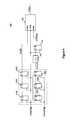
- FIG. 4illustrates a path delay measurement circuit 400 according to an embodiment of the invention.
- the path delay measurement circuit 400is configured to measure a path delay in terms of a number of clock cycles of a clock signal.
- the path delay measurement circuit 400may be used for the path delay measurement circuit 344 ( FIG. 3 ).
- the path delay measurement circuit 400includes a first series of data flip flops 410 A-C configured to receive a first clock signal (e.g., the GClk 2 PD signal of FIG. 1 ) and provide a clock enable signal CLKEN.
- the CLKEN signalis provided to a counter 450 as a start input.
- the GClk 2 PD signalfurther clocks the counter 450 .
- the path delay measurement circuit 400further includes a second series of data flip flops 420 A-C configured to receive a second clock signal (e.g., the WrDin 2 PD signal of FIG. 1 ) and provide a measurement delay clock signal MDCLK.
- the MDCLK signalis provided to a delay element 430 .
- the delay element 430provides a fixed minimum delay may be included to allow a clock circuit to which the forward path measurement circuit 400 is coupled to operate over a wide range of conditions.
- the amount of delay provided by the delay element 430may vary depending on the particular implementation.
- the delay element 430is coupled to a data flip flop 440 that is clocked by the GClk 2 PD signal to generate a measurement pulse signal MSTROBE.
- the MSTROBE signalis provided to the counter 450 as a stop input.
- the GClk 2 PD signalbegins to transition responsive to the XClk
- the first series of data flip flops 410 A-Care clocked.
- the XCmd signalpropagates, for example, through the command path 130 , to be provided as the WrDinDly signal and fed back on a feedback path through the model delay 152 , rising edges are seen in the WrDin 2 PD signal, which clocks the second series of data flip flops 420 A-C.
- the CLKEN signalis asserted, and the counter 450 begins counting each pulse of the GClk 2 PD signal.
- the WrDin 2 PD signalclocks second series of data flip flops 420 A-C, and after the third pulse, the MDCLK signal is asserted.
- the MDCLK signalpasses through the delay element 430 and is latched in the data flip flop 440 following the next rising edge of the GClk 2 PD signal, thus generating the MSTROBE signal.
- the MSTRBE signalstops the counter 450 .
- the start and stop signals provided to the counter 450are synchronized with the rising edge of the GClk 2 PD signal.
- the value of the counter 450 , PDtCKrepresents the number of clock cycles required for a command to propagate through the command path 130 .
- the PDtCK countis maintained in the counter 450 and stored and referenced when needed.
- three data flip flopsare included in the first and second series of data flip flops 410 A-C, 420 A-C to allow the command path to be populated with clock signals and stabilize. In other embodiments, however, the number of flip flops in the series of data flip flops 410 A-C, 420 A-C may vary depending on the particular implementation.
- FIG. 5illustrates a portion of a memory 500 according to an embodiment of the present invention.
- the memory 500includes an array 504 of memory cells, which may be, for example, DRAM memory cells, SRAM memory cells, flash memory cells, or some other types of memory cells.
- the memory 500includes a command path 514 that receives memory commands XCmd on a command bus 508 and provides internal memory signals, for example, a WrDinD signal.
- the command path 514may be implemented using a command path according to an embodiment of the invention.
- a decoder 506decodes the XCmd and generates corresponding control signals within the memory 500 to carry out various memory operations.
- the command decoder 506responds to memory commands applied to the command bus 508 to perform various operations on the memory array 504 .
- the command decoder 506is used to generate internal control signals to read data from and write data to the memory array 504 .
- the memory 500further includes a clock path 512 .
- the clock path 512receives a clock signal XClk and propagates an internal clock signal Clk, which is based at least in part on the XClk signal, to the command path 514 .
- Row and column address signalsare applied to the memory 500 through an address bus 520 and provided to an address latch 510 .
- the address latchthen provides a separate column address and a separate row address.
- the row and column addressesare provided by the address latch 510 to a row address decoder 522 and a column address decoder 528 , respectively.
- the column address decoder 528selects bit lines extending through the array 504 corresponding to respective column addresses.
- the row address decoder 522is connected to word line driver 524 that activates respective rows of memory cells in the array 504 corresponding to received row addresses.
- the selected data line(e.g., a bit line or bit lines) corresponding to a received column address are coupled to a read/write circuitry 530 to provide read data to an output data circuit 534 via an input-output data bus 540 .
- Write dataare applied to the memory array 504 through the input data circuit 536 and the memory array read/write circuitry 530 .
Landscapes
- Dram (AREA)
Abstract
Description
Claims (23)
Priority Applications (1)
| Application Number | Priority Date | Filing Date | Title |
|---|---|---|---|
| US13/543,698US9001594B2 (en) | 2012-07-06 | 2012-07-06 | Apparatuses and methods for adjusting a path delay of a command path |
Applications Claiming Priority (1)
| Application Number | Priority Date | Filing Date | Title |
|---|---|---|---|
| US13/543,698US9001594B2 (en) | 2012-07-06 | 2012-07-06 | Apparatuses and methods for adjusting a path delay of a command path |
Publications (2)
| Publication Number | Publication Date |
|---|---|
| US20140010025A1 US20140010025A1 (en) | 2014-01-09 |
| US9001594B2true US9001594B2 (en) | 2015-04-07 |
Family
ID=49878420
Family Applications (1)
| Application Number | Title | Priority Date | Filing Date |
|---|---|---|---|
| US13/543,698Active2033-02-19US9001594B2 (en) | 2012-07-06 | 2012-07-06 | Apparatuses and methods for adjusting a path delay of a command path |
Country Status (1)
| Country | Link |
|---|---|
| US (1) | US9001594B2 (en) |
Cited By (3)
| Publication number | Priority date | Publication date | Assignee | Title |
|---|---|---|---|---|
| US9111599B1 (en)* | 2014-06-10 | 2015-08-18 | Nanya Technology Corporation | Memory device |
| US10141935B2 (en) | 2015-09-25 | 2018-11-27 | Intel Corporation | Programmable on-die termination timing in a multi-rank system |
| US11726721B2 (en) | 2020-09-09 | 2023-08-15 | Samsung Electronics Co., Ltd. | Memory device for adjusting delay on data clock path, memory system including the memory device, and operating method of the memory system |
Families Citing this family (25)
| Publication number | Priority date | Publication date | Assignee | Title |
|---|---|---|---|---|
| US7716510B2 (en) | 2006-12-19 | 2010-05-11 | Micron Technology, Inc. | Timing synchronization circuit with loop counter |
| US7656745B2 (en) | 2007-03-15 | 2010-02-02 | Micron Technology, Inc. | Circuit, system and method for controlling read latency |
| US7969813B2 (en) | 2009-04-01 | 2011-06-28 | Micron Technology, Inc. | Write command and write data timing circuit and methods for timing the same |
| US8984320B2 (en) | 2011-03-29 | 2015-03-17 | Micron Technology, Inc. | Command paths, apparatuses and methods for providing a command to a data block |
| US8552776B2 (en) | 2012-02-01 | 2013-10-08 | Micron Technology, Inc. | Apparatuses and methods for altering a forward path delay of a signal path |
| US9166579B2 (en) | 2012-06-01 | 2015-10-20 | Micron Technology, Inc. | Methods and apparatuses for shifting data signals to match command signal delay |
| US9054675B2 (en) | 2012-06-22 | 2015-06-09 | Micron Technology, Inc. | Apparatuses and methods for adjusting a minimum forward path delay of a signal path |
| US9329623B2 (en) | 2012-08-22 | 2016-05-03 | Micron Technology, Inc. | Apparatuses, integrated circuits, and methods for synchronizing data signals with a command signal |
| US8913448B2 (en) | 2012-10-25 | 2014-12-16 | Micron Technology, Inc. | Apparatuses and methods for capturing data in a memory |
| US9734097B2 (en) | 2013-03-15 | 2017-08-15 | Micron Technology, Inc. | Apparatuses and methods for variable latency memory operations |
| US9727493B2 (en) | 2013-08-14 | 2017-08-08 | Micron Technology, Inc. | Apparatuses and methods for providing data to a configurable storage area |
| US9183904B2 (en) | 2014-02-07 | 2015-11-10 | Micron Technology, Inc. | Apparatuses, memories, and methods for facilitating splitting of internal commands using a shared signal path |
| US9508417B2 (en) | 2014-02-20 | 2016-11-29 | Micron Technology, Inc. | Methods and apparatuses for controlling timing paths and latency based on a loop delay |
| US9530473B2 (en) | 2014-05-22 | 2016-12-27 | Micron Technology, Inc. | Apparatuses and methods for timing provision of a command to input circuitry |
| US9531363B2 (en) | 2015-04-28 | 2016-12-27 | Micron Technology, Inc. | Methods and apparatuses including command latency control circuit |
| US9813067B2 (en) | 2015-06-10 | 2017-11-07 | Micron Technology, Inc. | Clock signal and supply voltage variation tracking |
| KR20170055786A (en)* | 2015-11-12 | 2017-05-22 | 삼성전자주식회사 | Memory device having latency control circuit for controlling data write and read latency |
| US9601170B1 (en) | 2016-04-26 | 2017-03-21 | Micron Technology, Inc. | Apparatuses and methods for adjusting a delay of a command signal path |
| US9865317B2 (en) | 2016-04-26 | 2018-01-09 | Micron Technology, Inc. | Methods and apparatuses including command delay adjustment circuit |
| US9997220B2 (en) | 2016-08-22 | 2018-06-12 | Micron Technology, Inc. | Apparatuses and methods for adjusting delay of command signal path |
| US10210918B2 (en) | 2017-02-28 | 2019-02-19 | Micron Technology, Inc. | Apparatuses and methods for determining a phase relationship between an input clock signal and a multiphase clock signal |
| US10090026B2 (en) | 2017-02-28 | 2018-10-02 | Micron Technology, Inc. | Apparatuses and methods for providing internal memory commands and control signals in semiconductor memories |
| US10224938B2 (en) | 2017-07-26 | 2019-03-05 | Micron Technology, Inc. | Apparatuses and methods for indirectly detecting phase variations |
| US10269397B2 (en) | 2017-08-31 | 2019-04-23 | Micron Technology, Inc. | Apparatuses and methods for providing active and inactive clock signals |
| CN115333667B (en)* | 2022-10-12 | 2023-01-24 | 中科声龙科技发展(北京)有限公司 | Method for adjusting time sequence and communication system |
Citations (69)
| Publication number | Priority date | Publication date | Assignee | Title |
|---|---|---|---|---|
| US5004933A (en) | 1986-06-02 | 1991-04-02 | Tektronix, Inc. | Phase-selectable flip-flop |
| US6111810A (en)* | 1998-09-30 | 2000-08-29 | Nec Corporation | Synchronous semiconductor memory device having burst access mode and multi-bit pre-fetch operation |
| US6219384B1 (en) | 1995-06-26 | 2001-04-17 | Phillip S. Kliza | Circuit for determining clock propagation delay in a transmission line |
| US6275077B1 (en) | 1999-08-31 | 2001-08-14 | Sun Microsystems, Inc. | Method and apparatus for programmable adjustment of bus driver propagation times |
| US20020057624A1 (en) | 1997-03-05 | 2002-05-16 | Manning Troy A. | Delay-locked loop with binary-coupled capacitor |
| US6424592B1 (en) | 2000-11-30 | 2002-07-23 | Mitsubishi Denki Kabushiki Kaisha | Semiconductor integrated circuit having circuit for correcting data output timing |
| US6459313B1 (en) | 1998-09-18 | 2002-10-01 | Lsi Logic Corporation | IO power management: synchronously regulated output skew |
| US6489823B2 (en) | 2000-10-18 | 2002-12-03 | Mitsubishi Denki Kabushiki Kaisha | Semiconductor device capable of generating highly precise internal clock |
| US6510095B1 (en) | 2001-09-28 | 2003-01-21 | Fujitsu Limited | Semiconductor memory device for operating in synchronization with edge of clock signal |
| US6636110B1 (en) | 1998-05-01 | 2003-10-21 | Mitsubishi Denki Kabushiki Kaisha | Internal clock generating circuit for clock synchronous semiconductor memory device |
| US6710726B2 (en) | 2002-04-03 | 2004-03-23 | Samsung Electronics Co., Ltd. | Serializer-deserializer circuit having increased margins for setup and hold time |
| US6781861B2 (en) | 2001-08-06 | 2004-08-24 | Micron Technology, Inc. | Method and apparatus for determining digital delay line entry point |
| US6839288B1 (en) | 2003-11-12 | 2005-01-04 | Infineon Technologies Ag | Latch scheme with invalid command detector |
| US20050024107A1 (en) | 2003-07-31 | 2005-02-03 | Elpida Memory, Inc | Delay circuit and delay sysnchronization loop device |
| US6861901B2 (en) | 2002-07-01 | 2005-03-01 | Texas Instruments Deutschland, Gmbh | Voltage follower circuit |
| US20050047222A1 (en) | 2003-08-27 | 2005-03-03 | Rentschler Eric Mccutcheon | Data signal reception latch control using clock aligned relative to strobe signal |
| US20050132043A1 (en) | 2003-12-12 | 2005-06-16 | Hon Hai Precision Industry Co., Ltd. | System and method for command line interface command processing |
| US6914798B2 (en) | 2001-06-30 | 2005-07-05 | Hynix Semiconductor Inc. | Register controlled DLL for reducing current consumption |
| US6930955B2 (en) | 2003-03-18 | 2005-08-16 | Micron Technology, Inc. | Method and apparatus for establishing and maintaining desired read latency in high-speed DRAM |
| US20050270852A1 (en) | 2004-05-27 | 2005-12-08 | Infineon Technologies Ag | Read latency control circuit |
| US6988218B2 (en) | 2002-02-11 | 2006-01-17 | Micron Technology, Inc. | System and method for power saving delay locked loop control by selectively locking delay interval |
| US20060062341A1 (en) | 2004-09-20 | 2006-03-23 | Edmondson John H | Fast-lock clock-data recovery system |
| US7042799B2 (en) | 2003-12-30 | 2006-05-09 | Hynix Semiconductor Inc. | Write circuit of double data rate synchronous DRAM |
| US7046060B1 (en) | 2004-10-27 | 2006-05-16 | Infineon Technologies, Ag | Method and apparatus compensating for frequency drift in a delay locked loop |
| US7061941B1 (en) | 2000-11-28 | 2006-06-13 | Winbond Electronics Corporation America | Data input and output circuits for multi-data rate operation |
| US7065001B2 (en) | 2004-08-04 | 2006-06-20 | Micron Technology, Inc. | Method and apparatus for initialization of read latency tracking circuit in high-speed DRAM |
| US20060182212A1 (en) | 2005-02-11 | 2006-08-17 | International Business Machines Corporation | Method and apparatus for generating synchronization signals for synchronizing multiple chips in a system |
| US20060193194A1 (en) | 2005-02-28 | 2006-08-31 | Josef Schnell | Data strobe synchronization for DRAM devices |
| US7119591B1 (en) | 2004-01-05 | 2006-10-10 | Integrated Device Technology, Inc. | Delay-locked loop (DLL) integrated circuits having binary-weighted delay chain units with built-in phase comparators that support efficient phase locking |
| US20070046346A1 (en) | 2005-08-30 | 2007-03-01 | Alessandro Minzoni | Clock controller with integrated DLL and DCC |
| US7248512B2 (en) | 2004-11-08 | 2007-07-24 | Hynix Semiconductor Inc. | Semiconductor memory device having controller with improved current consumption |
| US20070192651A1 (en) | 2002-08-12 | 2007-08-16 | Broadcom Corporation | Low-Speed DLL Employing a Digital Phase Interpolator based upon a High-Speed Clock |
| US7268605B2 (en) | 2004-06-14 | 2007-09-11 | Rambus, Inc. | Technique for operating a delay circuit |
| US20070291558A1 (en) | 2006-06-15 | 2007-12-20 | Hynix Semiconductor Inc. | Data strobe signal generator for generating data strobe signal based on adjustable preamble value and semiconductor memory device with the same |
| US7336752B2 (en) | 2002-12-31 | 2008-02-26 | Mosaid Technologies Inc. | Wide frequency range delay locked loop |
| US20080080267A1 (en) | 2006-09-29 | 2008-04-03 | Lee Hyeng Ouk | Data output control circuit and data output control method |
| US20080144423A1 (en) | 2006-12-19 | 2008-06-19 | Jongtae Kwak | Timing synchronization circuit with loop counter |
| US7463534B2 (en) | 2006-04-18 | 2008-12-09 | Hynix Semiconductor Inc. | Write apparatus for DDR SDRAM semiconductor memory device |
| US7489172B2 (en) | 2005-09-29 | 2009-02-10 | Hynix Semiconductor Inc. | DLL driver control circuit |
| US7509517B2 (en) | 2003-07-31 | 2009-03-24 | Advantest Corporation | Clock transferring apparatus for synchronizing input data with internal clock and test apparatus having the same |
| US20090232250A1 (en) | 2008-03-12 | 2009-09-17 | Takaaki Yamada | Communication system, receiver and reception method |
| US7593273B2 (en) | 2006-11-06 | 2009-09-22 | Altera Corporation | Read-leveling implementations for DDR3 applications on an FPGA |
| US7609584B2 (en) | 2005-11-19 | 2009-10-27 | Samsung Electronics Co., Ltd. | Latency control circuit and method thereof and an auto-precharge control circuit and method thereof |
| US7616040B2 (en) | 2006-12-08 | 2009-11-10 | Sony Corporation | Flip-flop and semiconductor integrated circuit |
| US7671648B2 (en) | 2006-10-27 | 2010-03-02 | Micron Technology, Inc. | System and method for an accuracy-enhanced DLL during a measure initialization mode |
| US20100066422A1 (en) | 2008-09-16 | 2010-03-18 | Jen-Che Tsai | Clock timing calibration circuit and clock timing calibration method for calibrating phase difference between different clock signals and related analog-to-digital conversion system using the same |
| US7698589B2 (en) | 2006-03-21 | 2010-04-13 | Mediatek Inc. | Memory controller and device with data strobe calibration |
| US20100232213A1 (en) | 2009-03-12 | 2010-09-16 | Hyong-Ryol Hwang | Control signal transmitting system of a semiconductor device |
| US7822904B2 (en) | 1999-07-29 | 2010-10-26 | Micron Technology, Inc. | Capturing read data |
| US7826583B2 (en) | 2006-10-31 | 2010-11-02 | Hynix Semiconductor Inc. | Clock data recovery apparatus |
| US7885365B2 (en) | 2007-08-31 | 2011-02-08 | International Business Machines Corporation | Low-power, low-area high-speed receiver architecture |
| US20110047319A1 (en) | 2009-08-18 | 2011-02-24 | Samsung Electronics Co., Ltd. | Memory devices and systems including write leveling operations and methods of performing write leveling operations in memory devices and systems |
| US7983094B1 (en) | 2006-11-06 | 2011-07-19 | Altera Corporation | PVT compensated auto-calibration scheme for DDR3 |
| US8018791B2 (en) | 2007-03-15 | 2011-09-13 | Micron Technology, Inc. | Circuit, system and method for controlling read latency |
| US8144529B2 (en)* | 2009-03-31 | 2012-03-27 | Intel Corporation | System and method for delay locked loop relock mode |
| US20120084575A1 (en) | 2010-09-30 | 2012-04-05 | Jose Luis Flores | Synchronized Voltage Scaling and Device Calibration |
| US8321714B2 (en) | 2010-07-16 | 2012-11-27 | Macroblock, Inc. | Serial controller and bi-directional serial controller |
| US8358546B2 (en) | 2009-11-13 | 2013-01-22 | Samsung Electronics Co., Ltd. | Semiconductor device having additive latency |
| US8392741B2 (en)* | 2010-02-04 | 2013-03-05 | Hynix Semiconductor Inc. | Latency control circuit and semiconductor memory device including the same |
| US20130141994A1 (en) | 2011-12-05 | 2013-06-06 | Elpida Memory, Inc. | Semiconductor device having skew detection circuit measuring skew between clock signal and data strobe signal |
| US20130194013A1 (en) | 2012-02-01 | 2013-08-01 | Micron Technology, Inc. | Apparatuses and methods for altering a forward path delay of a signal path |
| US8509011B2 (en) | 2011-04-25 | 2013-08-13 | Micron Technology, Inc. | Command paths, apparatuses, memories, and methods for providing internal commands to a data path |
| US20130250701A1 (en) | 2009-04-01 | 2013-09-26 | Micron Technology, Inc. | Write command and write data timing circuit and methods for timing the same |
| US20130321052A1 (en) | 2012-06-01 | 2013-12-05 | Micron Technology, Inc. | Methods and apparatuses for shifting data signals to match command signal delay |
| US20130342254A1 (en) | 2012-06-22 | 2013-12-26 | Micron Technology, Inc. | Apparatuses and methods for adjusting a minimum forward path delay of a signal path |
| US20140055184A1 (en) | 2012-08-22 | 2014-02-27 | Micron Technology, Inc | Apparatuses, integrated circuits, and methods for synchronizing data signals with a command signal |
| US20140119141A1 (en) | 2012-10-25 | 2014-05-01 | Micron Technology, Inc. | Apparatuses and methods for capturing data in a memory |
| US20140177359A1 (en) | 2012-12-24 | 2014-06-26 | Arm Limited | Method and apparatus for aligning a clock signal and a data strobe signal in a memory system |
| US8788896B2 (en) | 2012-01-11 | 2014-07-22 | Lsi Corporation | Scan chain lockup latch with data input control responsive to scan enable signal |
- 2012
- 2012-07-06USUS13/543,698patent/US9001594B2/enactiveActive
Patent Citations (76)
| Publication number | Priority date | Publication date | Assignee | Title |
|---|---|---|---|---|
| US5004933A (en) | 1986-06-02 | 1991-04-02 | Tektronix, Inc. | Phase-selectable flip-flop |
| US6219384B1 (en) | 1995-06-26 | 2001-04-17 | Phillip S. Kliza | Circuit for determining clock propagation delay in a transmission line |
| US20020057624A1 (en) | 1997-03-05 | 2002-05-16 | Manning Troy A. | Delay-locked loop with binary-coupled capacitor |
| US6636110B1 (en) | 1998-05-01 | 2003-10-21 | Mitsubishi Denki Kabushiki Kaisha | Internal clock generating circuit for clock synchronous semiconductor memory device |
| US6459313B1 (en) | 1998-09-18 | 2002-10-01 | Lsi Logic Corporation | IO power management: synchronously regulated output skew |
| US6111810A (en)* | 1998-09-30 | 2000-08-29 | Nec Corporation | Synchronous semiconductor memory device having burst access mode and multi-bit pre-fetch operation |
| US7822904B2 (en) | 1999-07-29 | 2010-10-26 | Micron Technology, Inc. | Capturing read data |
| US6275077B1 (en) | 1999-08-31 | 2001-08-14 | Sun Microsystems, Inc. | Method and apparatus for programmable adjustment of bus driver propagation times |
| US6489823B2 (en) | 2000-10-18 | 2002-12-03 | Mitsubishi Denki Kabushiki Kaisha | Semiconductor device capable of generating highly precise internal clock |
| US7061941B1 (en) | 2000-11-28 | 2006-06-13 | Winbond Electronics Corporation America | Data input and output circuits for multi-data rate operation |
| US6424592B1 (en) | 2000-11-30 | 2002-07-23 | Mitsubishi Denki Kabushiki Kaisha | Semiconductor integrated circuit having circuit for correcting data output timing |
| US6914798B2 (en) | 2001-06-30 | 2005-07-05 | Hynix Semiconductor Inc. | Register controlled DLL for reducing current consumption |
| US6781861B2 (en) | 2001-08-06 | 2004-08-24 | Micron Technology, Inc. | Method and apparatus for determining digital delay line entry point |
| US6510095B1 (en) | 2001-09-28 | 2003-01-21 | Fujitsu Limited | Semiconductor memory device for operating in synchronization with edge of clock signal |
| US6988218B2 (en) | 2002-02-11 | 2006-01-17 | Micron Technology, Inc. | System and method for power saving delay locked loop control by selectively locking delay interval |
| US6710726B2 (en) | 2002-04-03 | 2004-03-23 | Samsung Electronics Co., Ltd. | Serializer-deserializer circuit having increased margins for setup and hold time |
| US6861901B2 (en) | 2002-07-01 | 2005-03-01 | Texas Instruments Deutschland, Gmbh | Voltage follower circuit |
| US20070192651A1 (en) | 2002-08-12 | 2007-08-16 | Broadcom Corporation | Low-Speed DLL Employing a Digital Phase Interpolator based upon a High-Speed Clock |
| US7336752B2 (en) | 2002-12-31 | 2008-02-26 | Mosaid Technologies Inc. | Wide frequency range delay locked loop |
| US6930955B2 (en) | 2003-03-18 | 2005-08-16 | Micron Technology, Inc. | Method and apparatus for establishing and maintaining desired read latency in high-speed DRAM |
| US7509517B2 (en) | 2003-07-31 | 2009-03-24 | Advantest Corporation | Clock transferring apparatus for synchronizing input data with internal clock and test apparatus having the same |
| US20050024107A1 (en) | 2003-07-31 | 2005-02-03 | Elpida Memory, Inc | Delay circuit and delay sysnchronization loop device |
| US20050047222A1 (en) | 2003-08-27 | 2005-03-03 | Rentschler Eric Mccutcheon | Data signal reception latch control using clock aligned relative to strobe signal |
| US6839288B1 (en) | 2003-11-12 | 2005-01-04 | Infineon Technologies Ag | Latch scheme with invalid command detector |
| US20050132043A1 (en) | 2003-12-12 | 2005-06-16 | Hon Hai Precision Industry Co., Ltd. | System and method for command line interface command processing |
| US7042799B2 (en) | 2003-12-30 | 2006-05-09 | Hynix Semiconductor Inc. | Write circuit of double data rate synchronous DRAM |
| US7119591B1 (en) | 2004-01-05 | 2006-10-10 | Integrated Device Technology, Inc. | Delay-locked loop (DLL) integrated circuits having binary-weighted delay chain units with built-in phase comparators that support efficient phase locking |
| US20050270852A1 (en) | 2004-05-27 | 2005-12-08 | Infineon Technologies Ag | Read latency control circuit |
| US7268605B2 (en) | 2004-06-14 | 2007-09-11 | Rambus, Inc. | Technique for operating a delay circuit |
| US7065001B2 (en) | 2004-08-04 | 2006-06-20 | Micron Technology, Inc. | Method and apparatus for initialization of read latency tracking circuit in high-speed DRAM |
| US20060062341A1 (en) | 2004-09-20 | 2006-03-23 | Edmondson John H | Fast-lock clock-data recovery system |
| US7046060B1 (en) | 2004-10-27 | 2006-05-16 | Infineon Technologies, Ag | Method and apparatus compensating for frequency drift in a delay locked loop |
| US7248512B2 (en) | 2004-11-08 | 2007-07-24 | Hynix Semiconductor Inc. | Semiconductor memory device having controller with improved current consumption |
| US20060182212A1 (en) | 2005-02-11 | 2006-08-17 | International Business Machines Corporation | Method and apparatus for generating synchronization signals for synchronizing multiple chips in a system |
| US7209396B2 (en) | 2005-02-28 | 2007-04-24 | Infineon Technologies Ag | Data strobe synchronization for DRAM devices |
| US20060193194A1 (en) | 2005-02-28 | 2006-08-31 | Josef Schnell | Data strobe synchronization for DRAM devices |
| US20070046346A1 (en) | 2005-08-30 | 2007-03-01 | Alessandro Minzoni | Clock controller with integrated DLL and DCC |
| US7489172B2 (en) | 2005-09-29 | 2009-02-10 | Hynix Semiconductor Inc. | DLL driver control circuit |
| US7609584B2 (en) | 2005-11-19 | 2009-10-27 | Samsung Electronics Co., Ltd. | Latency control circuit and method thereof and an auto-precharge control circuit and method thereof |
| US7698589B2 (en) | 2006-03-21 | 2010-04-13 | Mediatek Inc. | Memory controller and device with data strobe calibration |
| US7463534B2 (en) | 2006-04-18 | 2008-12-09 | Hynix Semiconductor Inc. | Write apparatus for DDR SDRAM semiconductor memory device |
| US20070291558A1 (en) | 2006-06-15 | 2007-12-20 | Hynix Semiconductor Inc. | Data strobe signal generator for generating data strobe signal based on adjustable preamble value and semiconductor memory device with the same |
| US20080080267A1 (en) | 2006-09-29 | 2008-04-03 | Lee Hyeng Ouk | Data output control circuit and data output control method |
| US7671648B2 (en) | 2006-10-27 | 2010-03-02 | Micron Technology, Inc. | System and method for an accuracy-enhanced DLL during a measure initialization mode |
| US7826583B2 (en) | 2006-10-31 | 2010-11-02 | Hynix Semiconductor Inc. | Clock data recovery apparatus |
| US7593273B2 (en) | 2006-11-06 | 2009-09-22 | Altera Corporation | Read-leveling implementations for DDR3 applications on an FPGA |
| US7983094B1 (en) | 2006-11-06 | 2011-07-19 | Altera Corporation | PVT compensated auto-calibration scheme for DDR3 |
| US7616040B2 (en) | 2006-12-08 | 2009-11-10 | Sony Corporation | Flip-flop and semiconductor integrated circuit |
| US20140258764A1 (en) | 2006-12-19 | 2014-09-11 | Micron Technology, Inc. | Timing synchronization circuit with loop counter |
| US20100199117A1 (en) | 2006-12-19 | 2010-08-05 | Micron Technology, Inc. | Timing synchronization circuit with loop counter |
| US20080144423A1 (en) | 2006-12-19 | 2008-06-19 | Jongtae Kwak | Timing synchronization circuit with loop counter |
| US8018791B2 (en) | 2007-03-15 | 2011-09-13 | Micron Technology, Inc. | Circuit, system and method for controlling read latency |
| US20110298512A1 (en) | 2007-03-15 | 2011-12-08 | Micron Technology, Inc. | Circuit, system and method for controlling read latency |
| US7885365B2 (en) | 2007-08-31 | 2011-02-08 | International Business Machines Corporation | Low-power, low-area high-speed receiver architecture |
| US20090232250A1 (en) | 2008-03-12 | 2009-09-17 | Takaaki Yamada | Communication system, receiver and reception method |
| US20100066422A1 (en) | 2008-09-16 | 2010-03-18 | Jen-Che Tsai | Clock timing calibration circuit and clock timing calibration method for calibrating phase difference between different clock signals and related analog-to-digital conversion system using the same |
| US20100232213A1 (en) | 2009-03-12 | 2010-09-16 | Hyong-Ryol Hwang | Control signal transmitting system of a semiconductor device |
| US8144529B2 (en)* | 2009-03-31 | 2012-03-27 | Intel Corporation | System and method for delay locked loop relock mode |
| US20130250701A1 (en) | 2009-04-01 | 2013-09-26 | Micron Technology, Inc. | Write command and write data timing circuit and methods for timing the same |
| US20110047319A1 (en) | 2009-08-18 | 2011-02-24 | Samsung Electronics Co., Ltd. | Memory devices and systems including write leveling operations and methods of performing write leveling operations in memory devices and systems |
| US8358546B2 (en) | 2009-11-13 | 2013-01-22 | Samsung Electronics Co., Ltd. | Semiconductor device having additive latency |
| US8392741B2 (en)* | 2010-02-04 | 2013-03-05 | Hynix Semiconductor Inc. | Latency control circuit and semiconductor memory device including the same |
| US8321714B2 (en) | 2010-07-16 | 2012-11-27 | Macroblock, Inc. | Serial controller and bi-directional serial controller |
| US20120084575A1 (en) | 2010-09-30 | 2012-04-05 | Jose Luis Flores | Synchronized Voltage Scaling and Device Calibration |
| US8644096B2 (en) | 2011-04-25 | 2014-02-04 | Micron Technology, Inc. | Command paths, apparatuses, memories, and methods for providing internal commands to a data path |
| US8509011B2 (en) | 2011-04-25 | 2013-08-13 | Micron Technology, Inc. | Command paths, apparatuses, memories, and methods for providing internal commands to a data path |
| US20130329503A1 (en) | 2011-04-25 | 2013-12-12 | Micron Technology, Inc. | Command paths, apparatuses, memories, and methods for providing internal commands to a data path |
| US20130141994A1 (en) | 2011-12-05 | 2013-06-06 | Elpida Memory, Inc. | Semiconductor device having skew detection circuit measuring skew between clock signal and data strobe signal |
| US8788896B2 (en) | 2012-01-11 | 2014-07-22 | Lsi Corporation | Scan chain lockup latch with data input control responsive to scan enable signal |
| US20140035640A1 (en) | 2012-02-01 | 2014-02-06 | Micron Technology, Inc. | Apparatuses and methods for altering a forward path delay of a signal path |
| US20130194013A1 (en) | 2012-02-01 | 2013-08-01 | Micron Technology, Inc. | Apparatuses and methods for altering a forward path delay of a signal path |
| US20130321052A1 (en) | 2012-06-01 | 2013-12-05 | Micron Technology, Inc. | Methods and apparatuses for shifting data signals to match command signal delay |
| US20130342254A1 (en) | 2012-06-22 | 2013-12-26 | Micron Technology, Inc. | Apparatuses and methods for adjusting a minimum forward path delay of a signal path |
| US20140055184A1 (en) | 2012-08-22 | 2014-02-27 | Micron Technology, Inc | Apparatuses, integrated circuits, and methods for synchronizing data signals with a command signal |
| US20140119141A1 (en) | 2012-10-25 | 2014-05-01 | Micron Technology, Inc. | Apparatuses and methods for capturing data in a memory |
| US20140177359A1 (en) | 2012-12-24 | 2014-06-26 | Arm Limited | Method and apparatus for aligning a clock signal and a data strobe signal in a memory system |
Non-Patent Citations (2)
| Title |
|---|
| Related U.S. Appl. No. 13/531,341, filed Jun. 22, 2012. |
| Related U.S. Appl. No. 13/592,244, filed Aug. 22, 2012. |
Cited By (4)
| Publication number | Priority date | Publication date | Assignee | Title |
|---|---|---|---|---|
| US9111599B1 (en)* | 2014-06-10 | 2015-08-18 | Nanya Technology Corporation | Memory device |
| US10141935B2 (en) | 2015-09-25 | 2018-11-27 | Intel Corporation | Programmable on-die termination timing in a multi-rank system |
| US10680613B2 (en) | 2015-09-25 | 2020-06-09 | Intel Corporation | Programmable on-die termination timing in a multi-rank system |
| US11726721B2 (en) | 2020-09-09 | 2023-08-15 | Samsung Electronics Co., Ltd. | Memory device for adjusting delay on data clock path, memory system including the memory device, and operating method of the memory system |
Also Published As
| Publication number | Publication date |
|---|---|
| US20140010025A1 (en) | 2014-01-09 |
Similar Documents
| Publication | Publication Date | Title |
|---|---|---|
| US9001594B2 (en) | Apparatuses and methods for adjusting a path delay of a command path | |
| US9000817B2 (en) | Apparatuses and methods for altering a forward path delay of a signal path | |
| US10679683B1 (en) | Timing circuit for command path in a memory device | |
| US11087806B2 (en) | Apparatuses and methods for adjusting delay of command signal path | |
| US8644096B2 (en) | Command paths, apparatuses, memories, and methods for providing internal commands to a data path | |
| US9530473B2 (en) | Apparatuses and methods for timing provision of a command to input circuitry | |
| US10515676B2 (en) | Apparatuses and methods for determining a phase relationship between an input clock signal and a multiphase clock signal | |
| US8984320B2 (en) | Command paths, apparatuses and methods for providing a command to a data block | |
| US9054675B2 (en) | Apparatuses and methods for adjusting a minimum forward path delay of a signal path | |
| US8913448B2 (en) | Apparatuses and methods for capturing data in a memory | |
| US9601170B1 (en) | Apparatuses and methods for adjusting a delay of a command signal path | |
| CN110827875B (en) | Electronic device with time sequence adjusting mechanism | |
| US20170309320A1 (en) | Methods and apparatuses including command delay adjustment circuit | |
| US8531897B2 (en) | Delay control circuit and semiconductor memory device including the same | |
| WO2019156715A1 (en) | Techniques for command synchronization in a memory device | |
| CN112789678B (en) | Selectively controlling clock transfer to Data (DQ) system | |
| US7272054B2 (en) | Time domain bridging circuitry for use in determining output enable timing |
Legal Events
| Date | Code | Title | Description |
|---|---|---|---|
| AS | Assignment | Owner name:MICRON TECHNOLOGY, INC., IDAHO Free format text:ASSIGNMENT OF ASSIGNORS INTEREST;ASSIGNOR:BRINGIVIJAYARAGHAVAN, VENKAT;REEL/FRAME:028504/0449 Effective date:20120626 | |
| FEPP | Fee payment procedure | Free format text:PAYOR NUMBER ASSIGNED (ORIGINAL EVENT CODE: ASPN); ENTITY STATUS OF PATENT OWNER: LARGE ENTITY | |
| STCF | Information on status: patent grant | Free format text:PATENTED CASE | |
| CC | Certificate of correction | ||
| AS | Assignment | Owner name:U.S. BANK NATIONAL ASSOCIATION, AS COLLATERAL AGENT, CALIFORNIA Free format text:SECURITY INTEREST;ASSIGNOR:MICRON TECHNOLOGY, INC.;REEL/FRAME:038669/0001 Effective date:20160426 Owner name:U.S. BANK NATIONAL ASSOCIATION, AS COLLATERAL AGEN Free format text:SECURITY INTEREST;ASSIGNOR:MICRON TECHNOLOGY, INC.;REEL/FRAME:038669/0001 Effective date:20160426 | |
| AS | Assignment | Owner name:MORGAN STANLEY SENIOR FUNDING, INC., AS COLLATERAL AGENT, MARYLAND Free format text:PATENT SECURITY AGREEMENT;ASSIGNOR:MICRON TECHNOLOGY, INC.;REEL/FRAME:038954/0001 Effective date:20160426 Owner name:MORGAN STANLEY SENIOR FUNDING, INC., AS COLLATERAL Free format text:PATENT SECURITY AGREEMENT;ASSIGNOR:MICRON TECHNOLOGY, INC.;REEL/FRAME:038954/0001 Effective date:20160426 | |
| AS | Assignment | Owner name:U.S. BANK NATIONAL ASSOCIATION, AS COLLATERAL AGENT, CALIFORNIA Free format text:CORRECTIVE ASSIGNMENT TO CORRECT THE REPLACE ERRONEOUSLY FILED PATENT #7358718 WITH THE CORRECT PATENT #7358178 PREVIOUSLY RECORDED ON REEL 038669 FRAME 0001. ASSIGNOR(S) HEREBY CONFIRMS THE SECURITY INTEREST;ASSIGNOR:MICRON TECHNOLOGY, INC.;REEL/FRAME:043079/0001 Effective date:20160426 Owner name:U.S. BANK NATIONAL ASSOCIATION, AS COLLATERAL AGEN Free format text:CORRECTIVE ASSIGNMENT TO CORRECT THE REPLACE ERRONEOUSLY FILED PATENT #7358718 WITH THE CORRECT PATENT #7358178 PREVIOUSLY RECORDED ON REEL 038669 FRAME 0001. ASSIGNOR(S) HEREBY CONFIRMS THE SECURITY INTEREST;ASSIGNOR:MICRON TECHNOLOGY, INC.;REEL/FRAME:043079/0001 Effective date:20160426 | |
| AS | Assignment | Owner name:JPMORGAN CHASE BANK, N.A., AS COLLATERAL AGENT, ILLINOIS Free format text:SECURITY INTEREST;ASSIGNORS:MICRON TECHNOLOGY, INC.;MICRON SEMICONDUCTOR PRODUCTS, INC.;REEL/FRAME:047540/0001 Effective date:20180703 Owner name:JPMORGAN CHASE BANK, N.A., AS COLLATERAL AGENT, IL Free format text:SECURITY INTEREST;ASSIGNORS:MICRON TECHNOLOGY, INC.;MICRON SEMICONDUCTOR PRODUCTS, INC.;REEL/FRAME:047540/0001 Effective date:20180703 | |
| AS | Assignment | Owner name:MICRON TECHNOLOGY, INC., IDAHO Free format text:RELEASE BY SECURED PARTY;ASSIGNOR:U.S. BANK NATIONAL ASSOCIATION, AS COLLATERAL AGENT;REEL/FRAME:047243/0001 Effective date:20180629 | |
| MAFP | Maintenance fee payment | Free format text:PAYMENT OF MAINTENANCE FEE, 4TH YEAR, LARGE ENTITY (ORIGINAL EVENT CODE: M1551); ENTITY STATUS OF PATENT OWNER: LARGE ENTITY Year of fee payment:4 | |
| AS | Assignment | Owner name:MICRON TECHNOLOGY, INC., IDAHO Free format text:RELEASE BY SECURED PARTY;ASSIGNOR:MORGAN STANLEY SENIOR FUNDING, INC., AS COLLATERAL AGENT;REEL/FRAME:050937/0001 Effective date:20190731 | |
| AS | Assignment | Owner name:MICRON TECHNOLOGY, INC., IDAHO Free format text:RELEASE BY SECURED PARTY;ASSIGNOR:JPMORGAN CHASE BANK, N.A., AS COLLATERAL AGENT;REEL/FRAME:051028/0001 Effective date:20190731 Owner name:MICRON SEMICONDUCTOR PRODUCTS, INC., IDAHO Free format text:RELEASE BY SECURED PARTY;ASSIGNOR:JPMORGAN CHASE BANK, N.A., AS COLLATERAL AGENT;REEL/FRAME:051028/0001 Effective date:20190731 | |
| MAFP | Maintenance fee payment | Free format text:PAYMENT OF MAINTENANCE FEE, 8TH YEAR, LARGE ENTITY (ORIGINAL EVENT CODE: M1552); ENTITY STATUS OF PATENT OWNER: LARGE ENTITY Year of fee payment:8 |