US9001469B2 - Mid-loadbeam dual stage actuated (DSA) disk drive head suspension - Google Patents
Mid-loadbeam dual stage actuated (DSA) disk drive head suspensionDownload PDFInfo
- Publication number
- US9001469B2 US9001469B2US13/827,622US201313827622AUS9001469B2US 9001469 B2US9001469 B2US 9001469B2US 201313827622 AUS201313827622 AUS 201313827622AUS 9001469 B2US9001469 B2US 9001469B2
- Authority
- US
- United States
- Prior art keywords
- rail
- microactuator
- load beam
- head suspension
- planar section
- Prior art date
- Legal status (The legal status is an assumption and is not a legal conclusion. Google has not performed a legal analysis and makes no representation as to the accuracy of the status listed.)
- Active
Links
- 239000000725suspensionSubstances0.000titleclaimsabstractdescription70
- 230000009977dual effectEffects0.000titledescription5
- 239000011800void materialSubstances0.000claimsabstractdescription54
- 229910052751metalInorganic materials0.000claimsabstractdescription24
- 239000002184metalSubstances0.000claimsabstractdescription24
- 238000005452bendingMethods0.000claimsdescription16
- 230000004913activationEffects0.000claimsdescription6
- 238000004519manufacturing processMethods0.000claimsdescription3
- 239000000853adhesiveSubstances0.000description14
- 230000001070adhesive effectEffects0.000description14
- 239000004020conductorSubstances0.000description6
- 229910001220stainless steelInorganic materials0.000description6
- 239000010935stainless steelSubstances0.000description6
- 239000003351stiffenerSubstances0.000description6
- 238000000034methodMethods0.000description5
- 230000008901benefitEffects0.000description4
- 238000005530etchingMethods0.000description4
- 239000010410layerSubstances0.000description3
- 239000000463materialSubstances0.000description3
- 239000002033PVDF binderSubstances0.000description2
- 238000012986modificationMethods0.000description2
- 230000004048modificationEffects0.000description2
- 229920002981polyvinylidene fluoridePolymers0.000description2
- 230000008569processEffects0.000description2
- 230000035939shockEffects0.000description2
- 229910000679solderInorganic materials0.000description2
- 238000007792additionMethods0.000description1
- 239000012790adhesive layerSubstances0.000description1
- 230000015556catabolic processEffects0.000description1
- 230000008859changeEffects0.000description1
- 238000010276constructionMethods0.000description1
- 230000008878couplingEffects0.000description1
- 238000010168coupling processMethods0.000description1
- 238000005859coupling reactionMethods0.000description1
- 238000006731degradation reactionMethods0.000description1
- 238000006073displacement reactionMethods0.000description1
- PCHJSUWPFVWCPO-UHFFFAOYSA-NgoldChemical compound[Au]PCHJSUWPFVWCPO-UHFFFAOYSA-N0.000description1
- 239000010931goldSubstances0.000description1
- 229910052737goldInorganic materials0.000description1
- 238000002955isolationMethods0.000description1
- HFGPZNIAWCZYJU-UHFFFAOYSA-Nlead zirconate titanateChemical compound[O-2].[O-2].[O-2].[O-2].[O-2].[Ti+4].[Zr+4].[Pb+2]HFGPZNIAWCZYJU-UHFFFAOYSA-N0.000description1
- 229920000642polymerPolymers0.000description1
- 230000004044responseEffects0.000description1
- 238000000926separation methodMethods0.000description1
- 238000009987spinningMethods0.000description1
- 238000003466weldingMethods0.000description1
Images


Classifications
- G—PHYSICS
- G11—INFORMATION STORAGE
- G11B—INFORMATION STORAGE BASED ON RELATIVE MOVEMENT BETWEEN RECORD CARRIER AND TRANSDUCER
- G11B21/00—Head arrangements not specific to the method of recording or reproducing
- G11B21/16—Supporting the heads; Supporting the sockets for plug-in heads
- G11B21/18—Supporting the heads; Supporting the sockets for plug-in heads while the head is moving
- G—PHYSICS
- G11—INFORMATION STORAGE
- G11B—INFORMATION STORAGE BASED ON RELATIVE MOVEMENT BETWEEN RECORD CARRIER AND TRANSDUCER
- G11B5/00—Recording by magnetisation or demagnetisation of a record carrier; Reproducing by magnetic means; Record carriers therefor
- G11B5/48—Disposition or mounting of heads or head supports relative to record carriers ; arrangements of heads, e.g. for scanning the record carrier to increase the relative speed
- G11B5/4806—Disposition or mounting of heads or head supports relative to record carriers ; arrangements of heads, e.g. for scanning the record carrier to increase the relative speed specially adapted for disk drive assemblies, e.g. assembly prior to operation, hard or flexible disk drives
- G11B5/4873—Disposition or mounting of heads or head supports relative to record carriers ; arrangements of heads, e.g. for scanning the record carrier to increase the relative speed specially adapted for disk drive assemblies, e.g. assembly prior to operation, hard or flexible disk drives the arm comprising piezoelectric or other actuators for adjustment of the arm
Definitions
- the present inventionrelates generally to suspensions for disk drives.
- the inventionis a dual stage actuated (DSA) suspension and associated components.
- Dual stage actuated (DSA) suspensionsalso sometimes known as microactuated or second stage actuated suspensions
- Such head suspensionstypically include a base plate for attaching the head suspension to a disk drive actuator, a mounting region attached to the base plate, a load beam attached or integral to the mounting region, and a flexure supported by the load beam for mounting a magnetic read/write head slider.
- the one or more microactuatorsare incorporated to accurately and quickly position the head slider over the desired track on the magnetic disk.
- Suspensions of these typesare disclosed, for example, in the Schirle U.S. Pat. No. 6,621,653, the Kulangara U.S. Pat. No. 7,595,965, the Liu U.S. Patent Application Publication 2011/0228425 and the Okawara U.S. Patent Application Publication 2010/0067151. These references are incorporated herein by reference in their entireties and for all purposes.
- microactuators of head suspensionsare typically placed along the loading plate. However, such microactuators must move the distal portion of the base plate and the entire load beam. Relocating the microactuators distally can require the microactuators to move less mass, but distal repositioning of the microactuators may reduce the stroke actuation of the head slider and can cause stability challenges if the actuators are placed along the less stiff load beam. Efforts to miniaturize disk drive head suspensions while at the same time maintaining or increasing performance specifications results in a continuing need for improved DSA-related structures. DSA structures that can provide increased servo bandwidth, increased stroke, increased stability, and/or lower mass would be advantageous.
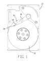
- FIG. 1is an overhead view of a disk drive having a mid-load beam dual stage actuated (DSA) disk drive head suspension.
- DSAmid-load beam dual stage actuated
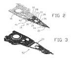
- FIG. 2is an isometric view of a mid-load beam DSA disk drive head suspension.
- FIG. 3is an isometric view of another embodiment that has a viscoelastic or other damper over the DSA structure, but is otherwise substantially the same as or similar to the suspension shown in FIG. 2 .
- FIG. 4is a detailed plan view of the DSA structure portion of the load beam of the suspension shown in FIG. 2 , showing the side of the load beam with the rails extending out of the page.
- FIG. 5Ais a cross section view along line A-A of FIG. 4 .
- FIG. 5Bis a cross section view along line B-B of FIG. 4 .
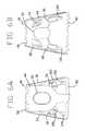
- FIG. 6Ais a detailed plan view of the DSA structure portion of the suspension shown in FIG. 2 , showing the flexure side with the rails extending into the page.
- FIG. 6Bis a detailed plan view of the opposite side of the load beam and DSA structure portion shown in FIG. 6A .
- FIG. 7is a detailed plan view of a DSA structure portion of a load beam showing the side of the load beam with the rails extending out of the page.
- FIG. 8Ais a detailed plan view of a DSA structure portion of a load beam with the microactuators mounted to tabs on the load beam.
- FIG. 8Bis a cross section view along line C-C of FIG. 8A .
- FIG. 9Ais a detailed plan view of a DSA structure portion of the load beam with the microactuators mounted to tabs on the load beam.
- FIG. 9Bis a cross section view along line D-D of FIG. 9A .
- Embodiments of the present inventionconcern a head suspension system.
- a head suspension systemcan comprise a base plate configured to attach to a disk drive actuation system and a load beam connected to the base plate along a spring region and extending distally from the base plate.
- a load beamcan comprise a major planar section having a proximal portion and a distal portion, a first rail extending along a first lateral edge of the major planar section, and a second rail extending along a second lateral edge of the major planar section, the first lateral edge opposite the second lateral edge.
- a load beamcan further include a continuous void in a metal base of the major planar section, the continuous void extending from the first rail to the second rail to separate the proximal portion from the distal portion.
- a first microactuatorcan be coupled to each of the proximal portion and the distal portion and extend across the continuous void.
- a second microactuatorcan be coupled to each of the proximal portion and the distal portion and extend across the continuous void.
- a head slider having circuitry configured to one or both of read and write data magneticallycan be positioned at the distal end of the load beam, mounted on either the distal portion and/or on flexure. The flexure can be electrically connected to each of the first microactuator and the second microactuator. Electrical activation of one or both of the first microactuator and the second microactuator can move the distal portion relative to the proximal portion to actuate the head slider laterally.
- the first and the second railsfunction as the structural linkage between the proximal portion and the distal portion of the load beam.
- the continuous void and linkageenable the distal portion of the load beam to move in a transverse or tracking direction along an X-Y plane with respect to the proximal portion.
- FIG. 1is an overhead view of a disk drive 10 .
- the disk drive 10includes a head suspension 14 .
- the head suspensionincludes a base plate 16 , a load beam 18 , and a head slider 20 .
- the head slider 20includes circuitry for magnetically writing to, and reading from, the disk 12 .
- the head suspension 14can be scanned over the disk 12 by a head suspension actuation system (not shown) as is known in the art. While movement of the whole head suspension 14 by the head suspension actuation system can provide relatively course position control of the head slider 20 , microactuations along the load beam 18 produced by the microactuators, as further described herein, can provide relatively fine positioning adjustment of the head slider 20 .
- FIG. 2is an isometric view of the head suspension 14 of FIG. 1 .
- the base plate 16 of the head suspension 14includes a proximal opening for mounting the head suspension 14 on the head suspension actuation system of the disk drive 10 .
- the base plate 16can be formed from a unitary metal structure that extends as a moveable cantilever.
- the base plate 16can be relatively stiff for securely mounting the head suspension 14 to the disk drive actuation system through the proximal hole.
- the base plate 16can be rigid such that the base plate 16 does not bend during normal operation of the disk drive 10 .
- the load beam 18is an elongated member that extends distally from the base plate 16 . As shown herein, the load beam 18 is generally triangularly shaped, although other shapes are possible.
- the load beam 18includes a proximal portion 42 and a distal portion 38 .
- the load beam 18can be attached to the base plate 16 along the spring region 46 .
- the spring region 46can include a single or multi-piece element. The spring region 46 operates to mechanically couple the load beam 18 to the base plate 16 .
- the spring region 46may be formed from a single stainless steel plate, and the same stainless steel plate may form the rest of the load beam 18 , including the first rail 34 and the second rail 36 .
- the load beam 18can be generally planar and can be oriented so as to be generally co-planar to the base plate 16 . In other embodiments, the load beam 18 may have other configurations. In other embodiments, the load beam 18 may be oriented out of plane with respect to the base plate 16 . Regardless of the nominal orientation, the load beam 18 may slightly rotate about the spring region 46 relative to the base plate 16 . Such movement of the load beam 18 can be caused by lift on the load beam 18 generated at the head slider 20 by the flow of air from the moving disk 12 during operation of the disk drive 10 . Such rotation of the load beam 18 about the spring region 46 causes the head slider 20 to move up or down (i.e. closer or further away from the disk 12 ) along the Z-axis. Rotation of the base plate 16 causes the head slider 20 to move left and right (i.e. laterally along the disk 12 ) over an X-Y plane (orthogonal to the Z-axis).
- a first rail 34 and a second rail 36are provided along the proximal portion 42 and distal portion 38 of the load beam 18 .
- the first rail 34 and the second rail 36can each extend along most or all of the load beam 18 distally of the spring region 46 such that, at least along the Z-axis, the load beam 18 is relatively flexible along spring region 46 and relatively stiff distally of the spring region 46 .
- the first rail 34 and the second rail 36are positioned on opposite lateral sides of the load beam 18 and extend generally along a longitudinal axis of the load beam 18 .
- the term “longitudinal axis” as used hereinrefers to an axis of an element that extends along the longest dimension of the element.
- a flexure 44is provided on the head suspension 14 .
- the flexure 44can be any type of flexible circuit having conductive traces for routing electrical signals between components of the head suspension 14 (e.g., read/write heads of the head slider 20 ) and other components of the disk drive 10 (e.g., a controller).
- the flexure 44can be manufactured as a separate member and welded to the load beam 18 or formed as an integral member of the load beam 18 .
- the air bearing head slider 20is located at the distal end of the distal portion 38 of the lead beam 18 and is designed to be resiliently moveable (e.g., gimbaled) with respect to load beam 18 in response to the aerodynamic forces generated as the disk 12 rotates relative to the head slider 20 .
- the head slider 20contains a magnetic head and is bonded to the flexure 44 by adhesive.
- the flexure 44allows the gimbal movement of the head slider 20 to follow variations in the surface of the disk 12 .
- air pressure at the surface of the spinning disk 12creates a positive pressure air bearing that causes the head slider 20 to lift away from and “fly” over the disk 12 .
- a negative pressure air bearingpulls the head slider 20 toward the disk 12 .
- the head suspension 14is mounted to the disk drive 10 with the suspension in a loaded state so the spring region 46 biases the head slider 20 either toward or away from the disk 12 to an appropriate fly height.
- a first microactuator 30 and a second microactuator 32are mounted on the load beam 18 .
- Each of the first microactuator 30 and the second microactuator 32comprise a generally planar element with a length (e.g., along a longitudinal axis) and a width.
- the first microactuator 30 and the second microactuator 32can be any suitable type of microactuator, whether now known or later developed.
- the first microactuator 30 and the second microactuator 32can each be a piezoelectric microactuator, which may include a piezoelectric layer of lead zirconium titanate, polymers such as polyvinylidene fluoride (PVDF), or other piezoelectric or electrostrictive types of materials.
- PVDFpolyvinylidene fluoride
- each microactuatorincludes terminals (not shown) for electrically coupling the microactuator to a power supply and to ground.
- the first microactuator 30 and the second microactuator 32may include multiple piezoelectric layers and/or may include different piezoelectric materials as are known in the art. Selective activation of the first microactuator 30 and a second microactuator 32 for controlling movement of the distal portion 38 of the load beam 18 is further discussed herein.
- FIG. 4shows a closer overhead view of a portion of the load beam 18 of FIG. 2 .
- the load beam 18is formed from a base structure.
- the base structureis typically a stainless steel sheet.
- the base structurecan be a unitary metal sheet forming each of the first rail 34 , the second rail 36 , and a major planar section 28 (shown in FIG. 5B ).
- the load beam 18is bisected by continuous void in the major planar section 28 of the load beam 18 , the void extending continuously from the first rail 34 on one lateral extreme of the load beam 18 to a second rail 36 on the opposite lateral extreme of the load beam 18 .
- the voidextends fully through the base structure of the load beam 18 such that the void is open on top and bottom sides of the load beam 18 .
- a continuous void in the base structure of the load beam 18divides the load beam 18 into the proximal portion 42 and the distal portion 38 .
- the load beam 18can be formed from a unitary metal element (e.g., a single sheet of stainless steel)
- the only part of the unitary metal element that extends between the proximal portion 42 and the distal portion 38may be the first rail 34 and the second rail 36 , as the cutout eliminates any direct connection of the base structure between the proximal portion 42 and the distal portion 38 along the major planar section 28 of the load beam 18 .
- the first rail 34 and the second rail 36can function as the main or only structural linkages between the proximal portion 42 and the distal portion 38 of the load beam 18 which has particular advantages as discussed herein.
- the voidin spanning from the first rail 34 to the second rail 36 , can be formed by multiple sections.
- the voidcan be formed, in part, by a tooling hole 72 .
- the tooling hole 72can be rounded to avoid stress points in the load beam 18 during bending. It is noted that not all embodiments may include a tooling hole 72 .
- the voidincludes crossbeam cutout 70 that connects a void of a first pocket 80 with a void of a second pocket 82 .
- the first microactuator 30can be placed over and/or within the first pocket 80 while the second microactuator 32 can be placed over and/or within the second pocket 82 , as further discussed herein.
- the first microactuator 30can span across the first pocket 80 to be attached to each of the proximal portion 42 and the distal portion 38 .
- the second microactuator 32can span across the second pocket 82 and be attached to each of the proximal portion 42 and the distal portion 38 .
- Each microactuatorcan be attached to the proximal portion 42 and the distal portion 38 by adhesive or other connection technique.
- the void spanning across the load beam 18includes the first lateral cutout 74 that extends the void of the first pocket 80 to underneath the first rail 34 .
- the second lateral cutout 76extends the void of the second pocket 82 to underneath the second rail 36 .
- the voidin some alternative embodiments, may not extend fully between the first rail 34 and the second rail 36 .
- the first lateral cutout 74 and/or the second lateral cutout 76may not be present.
- one or more bridges of base structuremay extend between the proximal portion 42 and the distal portion 38 .
- FIG. 5Ais a cross sectional view along line A-A of FIG. 4 .
- FIG. 5Bis a cross sectional view along line B-B of FIG. 4 .
- FIGS. 5A-Bshow that each of the first rail 34 and the second rail 36 are oriented substantially orthogonal to the major planar section 28 of the load beam 18 .
- FIG. 5Balso shows that each of the first microactuator 30 and the second microactuator 32 are mechanically connected to the load beam 18 by a first coupler 90 and a second coupler 92 , respectively.
- the first coupler 90 and the second coupler 92may comprise a layer of adhesive.
- the adhesivemay be deposited on each of the proximal portion 42 and the distal portion 38 to mechanically connect each of the first microactuator 30 and the second microactuator 32 to the proximal portion 42 and the distal portion 38 .
- a longitudinal axis of the first microactuator 30can extend parallel with a longitudinal axis of the first rail 34 while a longitudinal axis of the second microactuator 32 can extend parallel with a longitudinal axis of the second rail 36 , while the longitudinal axis of the first microactuator 30 is not parallel with the longitudinal axis of the second rail 36 and the longitudinal axis of the second microactuator 32 is not parallel with the longitudinal axis of the first rail 34 .
- an applied electrical voltage across the first microactuator 30 and/or second microactuator 32causes them to expand or contract, thereby causing deformation load beam 18 .
- This deflectionprovides high resolution positioning of the head slider 20 .
- lateral motion of the head slider 20can be generated along an X-Y plane that runs parallel to the disk 12 , as further discussed herein.
- Various electronic control circuits for controlling the piezoelectric actuators to perform the functions discussed hereinare disclosed in U.S. Pat. No. 5,377,058 (Good et al.); U.S. Pat. No. 5,719,720 (Lee); and U.S. Pat. No. 5,802,701 (Fontana et al.), each of which is incorporated herein by reference in its entirety.
- flat elementssuch as the major planar section 28 , the first rail 34 , and the second rail 36 , in isolation, generally bend relatively easily in the two opposing directions that are orthogonal to the major plane of the flat element but resist bending along an axis that is parallel with the major plane.
- the first rail 34 and the second rail 36are both orthogonal to the major planar section 28 of the load beam 18
- the first rail 34 and the second rail 36resist bending of the load beam 18 in a direction orthogonal to the major planar section 28 (e.g., along the Z-axis), stiffening the load beam 18 to movement in the Z-axis.
- bending of the head suspension 14 that would move the head slider 20 closer or further away from the disk 12 along the Z-axisis generally isolated to the spring region 46 , where the first rail 34 and the second rail 36 do not extend.
- the major planar section 28would generally resist bending of the load beam 18 in a direction orthogonal to the first rail 34 and the second rail 36 (i.e. lateral swaying of the load beam 18 ).
- the continuous void in the major planar section 28allows the distal portion 42 to move along an X-Y plane relative to the proximal portion 42 and thereby facilitate lateral translation of the head slider 20 over the disk 12 .
- the continuous void in the base structurecan allow movement of the distal portion 38 relative to the proximal portion 42 , widening or narrowing at least a portion of the void during movement of the distal portion 38 relative to the proximal portion 42 .
- the load beam 18can be laterally actuated through bending in each of the first rail 34 and the second rail 36 , the bending driven by the first microactuator 30 and the second microactuator 32 being oppositely expanded and contracted.
- Suspensions having DSA structures in accordance with the present disclosurecan provide several advantages.
- Total strokes of 100 nm or morecan be achieved (e.g., at 5-6 nm/V), although the invention can be used in suspensions configured for less stroke.
- the presence of the crossbeam cutout 70 to the tooling hole 72increased stroke by 43% while the first lateral cutout 74 and the second lateral cutout 76 increased stroke by 39%.
- the location of the continuous void as being between the proximal flexure welds 64 and 66 on the distal flexure welds 60 and 62also increased stroke and minimized shock impact.
- the DSA structurecan be efficiently manufactured using conventional or otherwise known processes and equipment. Servo bandwidths can be significantly enhanced. Enhanced stroke and tracking specifications can be achieved. These advantages can be achieved with little or no degradation of shock and resonance performance.
- a microactuatorcan have a width of 0.25 mm or less, and a thickness of 0.0762 mm or less.
- other embodiments of the inventionmay have microactuators with other (e.g., greater) widths and/or thicknesses (e.g., about 0.102 mm).
- each microactuatorcan be selected and optimized with other parameters of the DSA structure to achieve the desired stroke length.
- the microactuatorscan be about 0.75 mm in length.
- the first microactuator 30is adjacent to the first rail 34 while the second microactuator 32 is adjacent to the second rail 36 .
- the longitudinal axis of the first microactuator 30extends parallel with the first rail 34 .
- the longitudinal axis of the first microactuator 30is not parallel with neither the longitudinal axis of the second microactuator 36 nor the second rail 36 .
- the longitudinal axis of the second microactuator 36extends parallel with the second rail 36 .
- the longitudinal axis of the second microactuator 36is not parallel with neither the longitudinal axis of the first microactuator 30 nor the first rail 34 .
- the first microactuator 30is not parallel with neither the second microactuator 36
- the flexure 44can extend over the head suspension 14 , including the load beam 18 , to route electrical signals between control circuitry and read/write elements of the head slider 20 .
- the flexure 44can be supported by flexure welds 60 , 62 , 64 , and 66 on the load beam 18 .
- each of flexure welds 60 , 62 , 64 , and 66can provide a location for welding the flexure 44 to the load beam 18 to mechanically support the flexure 44 and/or provide a ground electrical connection to the load beam 18 .
- the base plate 16 and the load beam 18can be formed using any suitable technique, e.g., etching and bending a metal base structure such as a stainless steel sheet.
- the load beam 18can be formed by etching a plurality of cutouts in a metal sheet, the plurality of cutouts corresponding to the voids, holes, and other features in the metal base shown herein. The etching can create the continuous void in the metal sheet.
- Forming the load beam 18can further comprise bending the metal sheet to form the first rail 34 and the second rail 36 .
- the metal sheetis etched before bending or other features are formed, however, etching can occur after one or more bending steps have been performed.
- the flexure 44can be welded to the load beam 18 .
- the first microactuator 30 and the second microactuator 32can be positioned over or in the first pocket 80 and attached to the proximal portion 42 and the distal portion 38 using, for example, an adhesive or other technique providing a mechanical bond.
- the second microactuator 32can be mounted similarly over or within the second pocket 82 .
- the head suspension 52 of FIG. 3can be similar in construction and function to the head suspension 14 of FIG. 2 (or as otherwise referenced herein), except that the head suspension 52 includes a damper 50 .
- the damper 50can be formed from viscoelastic or other suitable material to dampen vibration between the proximal portion and the distal portion of a load beam of the head suspension 14 .
- the damper 52can be mounted over or underneath the microactuators (not illustrated) and optionally further can be connected to each of the proximal portion and the distal portion of the load beam of a head suspension to damped movement across the continuous void between the proximal portion and the distal portion.
- the damper 52can suppress resonance vibration that can result when the head slider 20 floats over the disk 12 while the disk 12 rotates at high speed.
- FIG. 6Ashows a bottom view of a portion of the load beam 18 while FIG. 6B shows a top view of the portion of the load beam 18 .
- FIGS. 6A-Bshow how the flexure 44 can electrically connect with each of the first microactuator 30 and the second microactuator 32 .
- the flexure 44can extend along the bottom side of the load beam 18 .
- a first lead 100can branch from the flexure 44 to contact the first microactuator 30 , where an electrical connection can be made to power the first microactuator 30 through the first lead 100 .
- a conductive trace of the first lead 100can be soldered or adhered with conductive adhesive to a terminal of the first microactuator 30 .
- a second lead 104can also branch from the flexure 44 to extend over the first through-hole 65 in the load beam 18 , the first through-hole 65 connecting with the top side of the load beam 18 .
- the second lead 104can include a conductive trace that electrically connects with a conductor that extends through the first through-hole 65 to the top side of the load beam 18 .
- a first bridge 112can be connected to the proximal portion 42 .
- the first bridge 112can be formed from an electrically conductive material (e.g., an electrically conductive adhesive) or can contain an electrical conductor.
- the first bridge 112can extend to the first microactuator 30 to make an electrical connection with a terminal of the first microactuator 30 (e.g., by electrically conductive adhesive).
- a mass of electrically conductive adhesivecan fill the first through-hole 65 to electrically connect with the first lead 100 and can further extend to make a mechanical and electrical connection with the first microactuator 30 .
- Goldcan be plated onto the load beam 18 at locations where the electrically conductive adhesive is attached to enhance the electrical ground connection.
- the first lead 100 and the second lead 104can facilitate electrical connections to respective anode and cathode terminals of the first microactuator 30 to power the first microactuator 30 .
- Other arrangements for electrically powering the first microactuator 30 from the flexure 44 or other sourceare alternatively possible.
- a third lead 102can branch from the flexure 44 to contact the second microactuator 32 , where an electrical connection can be made to power the second microactuator 32 through the third lead 102 .
- a conductive trace of the third lead 102can be soldered or adhered with conductive adhesive to a terminal of the second microactuator 32 .
- a fourth lead 106can also branch from the flexure 44 to extend over the second through-hole 67 in the load beam 18 , the second through-hole 67 connecting with the top side of the load beam 18 .
- the fourth lead 106can include a conductive trace that electrically connects with a conductor that extends through the second through-hole 67 to the top side of the load beam 18 .
- a second bridge 110can be connected to the proximal portion 42 .
- the second bridge 110can be formed from an electrically conductive material (e.g., an electrically conductive adhesive, solder) or can contain an electrical conductor.
- the second bridge 110can extend to the second microactuator 32 to make an electrical connection with a terminal of the second microactuator 32 (e.g., by electrically conductive adhesive, solder).
- a mass of electrically conductive adhesivecan fill the second through-hole 67 to electrically connect with the third lead 102 and can further extend to make a mechanical and electrical connection with the second microactuator 32 .
- the third lead 102 and the fourth lead 106can facilitate electrical connections to respective anode and cathode terminals of the second microactuator 32 to power the second microactuator 32 .
- Other arrangements for electrically powering the second microactuator 32 from the flexure 44 or other sourceare alternatively possible.
- FIGS. 2-6Billustrate embodiments where the continuous void traverses from the first rail 34 to the second rail 36 by branching to the tooling hole 72
- a continuous voidmay not include the tooling hole 72 in some other embodiments.
- FIG. 7illustrates a portion of a load beam 218 that can be similar to any embodiment referenced herein except that the crossbeam cutout 270 of the continuous void that extends from the first rail 234 to the second rail 236 does not include the tooling hole 272 .
- the load beam 218is shown to include stiffener members 254 .
- the load beam 218can be manufactured initially with stiffener members 254 on a base structure (e.g., stainless steel) of the load beam 218 .
- the stiffener members 254can extend from the proximal portion 242 to the distal portion 238 of the load beam 218 .
- the stiffener members 254can stiffen the structure of the load beam 218 , which is generally relatively thin.
- the stiffener members 254can thereby enhance the ability of the load beam 218 to be handled during manufacturing steps such as forming of the first rail 234 , the second rail 236 , or a radius region and/or in processes for attaching the first microactuator 230 and the second microactuator 232 .
- the crossbeam cutout 270can include a de-tabbed void 252 , which is shown to include stubs.
- the de-tabbed void 252can allow the crossbeam cutout 270 to change orientations such that the crossbeam cutout 270 is symmetrical between left and right sides while not extending straight across the load beam 218 .
- a tooling holeas presented in other embodiments, can provide the same function.
- the stiffener members 254can be removed after one, multiple, or all of the above referenced assembly steps are complete.
- FIG. 8Aillustrates a portion of a load beam 318 .
- FIG. 8Bshows a cross sectional view of the load beam 318 along line C-C.
- the load beam 318can be similar to any load beam configuration referenced herein.
- the load beam 318includes a proximal portion 342 , a distal portion 338 , a first microactuator 330 , a second microactuator 332 , a first rail 334 , and a second rail 336 .
- a continuous void extending from the first rail 334 to the second rail 336is formed in the load beam 318 by a first lateral cutout 374 extending from the first rail 334 to a first pocket 380 , a crossbeam cutout 370 extending between the first pocket 380 and a second pocket 382 , and second lateral cutout 376 extending from the second pocket 382 to the second rail 336 .
- the continuous void extending from the first rail 334 to the second rail 336can allow lateral bending and vertical stiffness between the proximal portion 342 and the distal portion 338 as described herein.
- the load beam 318can include tabs for supporting the first microactuator 330 and the second microactuator 332 .
- the load beam 318includes a first proximal tab 396 and a first distal tab 394 .
- the first proximal tab 396 and/or the first distal tab 394can be formed from the same base structure as the first rail 334 and the major planar section of the load beam 318 .
- the first proximal tab 396 and/or the first distal tab 394can be left in place as a metal sheet is etched and bent to form the base structure of the load beam 318 .
- the first proximal tab 396 and/or the first distal tab 394can separately attached to the base structure of the load beam 318 .
- the first proximal tab 396can be continuous with the base structure of the major planar section of the load beam 318 such that the first proximal tab 396 is formed from the same unitary body as the base structure of the major planar section of the load beam 318 .
- the first proximal tab 396can be formed separately and attached to the base structure of the major planar section of the load beam 318 .
- the first proximal tab 396can be formed separately and adhered to a proximal edge of the first pocket 380 .
- the first proximal tab 396can be bent or attached to the load beam 318 so as to extend over or underneath the first pocket 380 and therefore not extend within the first pocket 380 .
- the first distal tab 394can extend from the first rail 334 over or below the first pocket 380 . As shown, the first distal tab 394 can extend from the top of the first rail 334 as a cantilever. The first distal tab 394 can be continuous with the first rail 334 such that the first distal tab 394 is formed from the same unitary body as the first rail 334 . Alternatively, the first distal tab 394 can be formed separately and attached to the first rail 334 . Adhesive layers 386 and 388 can be provided to couple the first microactuator 330 to the first distal tab 394 and the first proximal tab 396 , respectively.
- the first distal tab 394 and the first proximal tab 396can be aligned over or underneath the first pocket 380 such that the first actuator 330 can be placed within the first pocket 380 such that one side of the first actuator 330 contacts both of the first distal tab 394 and the first proximal tab 396 while the first microactuator 330 remains coplanar or parallel with the major planar surface of the load beam 318 .
- Such alignmentcan isolate the expansion of the first actuator 330 to increase or decrease the separation between the proximal portion 342 and the distal portion 338 while minimizing torsion between the proximal portion 342 and the distal portion 338 .
- first actuator 330displacement of the first distal tab 394 and the first proximal tab 396 above or below the first pocket 380 allows the first actuator 330 to be directly placed into the first pocket 380 and onto the first distal tab 394 and the first proximal tab 396 from the bottom or top of the load beam 318 .
- the second microactuator 332can be mounted within the second pocket 382 and supported by the second proximal tab 392 and the second distal tap 398 in the same manner as described herein for the first microactuator 330 , the first distal tab 394 , and the first proximal tab 396 to have a mirrored structure and function.
- FIG. 9Aillustrates a portion of a load beam 418 .
- FIG. 9Bshows a cross sectional view of the load beam 418 along line D-D.
- the load beam 418can be structurally and functionally similar to the load beam 318 of FIGS. 8A-B except that the first proximal tab 496 extends from the first rail 434 while the first distal tab 494 extends from distal edge of the first pocket 480 .
- the first proximal tab 496can be attached to the first rail 434 in the same manner as the first distal tab 394 is attached to the first rail 334 .
- first distal tab 494can be attached to the base structure of the major planar section of the load beam 418 in the same manner as the first proximal tab 396 is attached to the base structure of the major planar section of the load beam 318 .
- the second microactuator 432can be mounted within the second pocket 482 and supported by the second proximal tab 492 and the second distal tap 498 in the same manner as described herein for the first microactuator 430 , the first distal tab 494 , and the first proximal tab 496 (or as otherwise described herein) to have a mirrored structure and function.
- a flexurecan be configured with tabs that extend into the pocket of the continuous, and the microactuators can be mounted to the tabs of the flexure.
Landscapes
- Supporting Of Heads In Record-Carrier Devices (AREA)
Abstract
Description
This application claims the benefit of U.S. Provisional Application Ser. No. 61/611,962 filed on Mar. 16, 2012 and entitled Mid-Loadbeam Dual Stage Actuated (DSA) Disk Drive Head Suspension, which is incorporated herein by reference for all purposes.
The present invention relates generally to suspensions for disk drives. In particular, the invention is a dual stage actuated (DSA) suspension and associated components.
Dual stage actuated (DSA) suspensions, also sometimes known as microactuated or second stage actuated suspensions, are generally known. Such head suspensions typically include a base plate for attaching the head suspension to a disk drive actuator, a mounting region attached to the base plate, a load beam attached or integral to the mounting region, and a flexure supported by the load beam for mounting a magnetic read/write head slider. The one or more microactuators are incorporated to accurately and quickly position the head slider over the desired track on the magnetic disk. Suspensions of these types are disclosed, for example, in the Schirle U.S. Pat. No. 6,621,653, the Kulangara U.S. Pat. No. 7,595,965, the Liu U.S. Patent Application Publication 2011/0228425 and the Okawara U.S. Patent Application Publication 2010/0067151. These references are incorporated herein by reference in their entireties and for all purposes.
The microactuators of head suspensions are typically placed along the loading plate. However, such microactuators must move the distal portion of the base plate and the entire load beam. Relocating the microactuators distally can require the microactuators to move less mass, but distal repositioning of the microactuators may reduce the stroke actuation of the head slider and can cause stability challenges if the actuators are placed along the less stiff load beam. Efforts to miniaturize disk drive head suspensions while at the same time maintaining or increasing performance specifications results in a continuing need for improved DSA-related structures. DSA structures that can provide increased servo bandwidth, increased stroke, increased stability, and/or lower mass would be advantageous.
Embodiments of the present invention concern a head suspension system. Such a head suspension system can comprise a base plate configured to attach to a disk drive actuation system and a load beam connected to the base plate along a spring region and extending distally from the base plate. Such a load beam can comprise a major planar section having a proximal portion and a distal portion, a first rail extending along a first lateral edge of the major planar section, and a second rail extending along a second lateral edge of the major planar section, the first lateral edge opposite the second lateral edge. A load beam can further include a continuous void in a metal base of the major planar section, the continuous void extending from the first rail to the second rail to separate the proximal portion from the distal portion. A first microactuator can be coupled to each of the proximal portion and the distal portion and extend across the continuous void. Likewise, a second microactuator can be coupled to each of the proximal portion and the distal portion and extend across the continuous void. A head slider having circuitry configured to one or both of read and write data magnetically can be positioned at the distal end of the load beam, mounted on either the distal portion and/or on flexure. The flexure can be electrically connected to each of the first microactuator and the second microactuator. Electrical activation of one or both of the first microactuator and the second microactuator can move the distal portion relative to the proximal portion to actuate the head slider laterally.
The first and the second rails function as the structural linkage between the proximal portion and the distal portion of the load beam. The continuous void and linkage enable the distal portion of the load beam to move in a transverse or tracking direction along an X-Y plane with respect to the proximal portion.
Theload beam 18 is an elongated member that extends distally from thebase plate 16. As shown herein, theload beam 18 is generally triangularly shaped, although other shapes are possible. Theload beam 18 includes aproximal portion 42 and adistal portion 38. Theload beam 18 can be attached to thebase plate 16 along thespring region 46. Thespring region 46 can include a single or multi-piece element. Thespring region 46 operates to mechanically couple theload beam 18 to thebase plate 16. Thespring region 46 may be formed from a single stainless steel plate, and the same stainless steel plate may form the rest of theload beam 18, including thefirst rail 34 and thesecond rail 36.
Theload beam 18 can be generally planar and can be oriented so as to be generally co-planar to thebase plate 16. In other embodiments, theload beam 18 may have other configurations. In other embodiments, theload beam 18 may be oriented out of plane with respect to thebase plate 16. Regardless of the nominal orientation, theload beam 18 may slightly rotate about thespring region 46 relative to thebase plate 16. Such movement of theload beam 18 can be caused by lift on theload beam 18 generated at thehead slider 20 by the flow of air from the movingdisk 12 during operation of thedisk drive 10. Such rotation of theload beam 18 about thespring region 46 causes thehead slider 20 to move up or down (i.e. closer or further away from the disk12) along the Z-axis. Rotation of thebase plate 16 causes thehead slider 20 to move left and right (i.e. laterally along the disk12) over an X-Y plane (orthogonal to the Z-axis).
While bending along thespring region 46 of theload beam 18 may be expected for proper operation of thehead suspension 14, bending of theload beam 18 in the Z-axis distally of thespring region 46 is generally unwanted. Therefore, afirst rail 34 and asecond rail 36 are provided along theproximal portion 42 anddistal portion 38 of theload beam 18. Thefirst rail 34 and thesecond rail 36 can each extend along most or all of theload beam 18 distally of thespring region 46 such that, at least along the Z-axis, theload beam 18 is relatively flexible alongspring region 46 and relatively stiff distally of thespring region 46. Thefirst rail 34 and thesecond rail 36 are positioned on opposite lateral sides of theload beam 18 and extend generally along a longitudinal axis of theload beam 18. The term “longitudinal axis” as used herein refers to an axis of an element that extends along the longest dimension of the element.
Aflexure 44 is provided on thehead suspension 14. Theflexure 44 can be any type of flexible circuit having conductive traces for routing electrical signals between components of the head suspension14 (e.g., read/write heads of the head slider20) and other components of the disk drive10 (e.g., a controller). Theflexure 44 can be manufactured as a separate member and welded to theload beam 18 or formed as an integral member of theload beam 18.
The airbearing head slider 20 is located at the distal end of thedistal portion 38 of thelead beam 18 and is designed to be resiliently moveable (e.g., gimbaled) with respect to loadbeam 18 in response to the aerodynamic forces generated as thedisk 12 rotates relative to thehead slider 20. Thehead slider 20 contains a magnetic head and is bonded to theflexure 44 by adhesive. Theflexure 44 allows the gimbal movement of thehead slider 20 to follow variations in the surface of thedisk 12. As noted above, air pressure at the surface of thespinning disk 12 creates a positive pressure air bearing that causes thehead slider 20 to lift away from and “fly” over thedisk 12. In some cases, a negative pressure air bearing pulls thehead slider 20 toward thedisk 12. To counteract these hydrodynamic forces, thehead suspension 14 is mounted to thedisk drive 10 with the suspension in a loaded state so thespring region 46 biases thehead slider 20 either toward or away from thedisk 12 to an appropriate fly height.
Afirst microactuator 30 and asecond microactuator 32 are mounted on theload beam 18. Each of thefirst microactuator 30 and thesecond microactuator 32 comprise a generally planar element with a length (e.g., along a longitudinal axis) and a width. Thefirst microactuator 30 and thesecond microactuator 32 can be any suitable type of microactuator, whether now known or later developed. For example, thefirst microactuator 30 and thesecond microactuator 32 can each be a piezoelectric microactuator, which may include a piezoelectric layer of lead zirconium titanate, polymers such as polyvinylidene fluoride (PVDF), or other piezoelectric or electrostrictive types of materials. As will be appreciated, each microactuator includes terminals (not shown) for electrically coupling the microactuator to a power supply and to ground. Thefirst microactuator 30 and thesecond microactuator 32 may include multiple piezoelectric layers and/or may include different piezoelectric materials as are known in the art. Selective activation of thefirst microactuator 30 and asecond microactuator 32 for controlling movement of thedistal portion 38 of theload beam 18 is further discussed herein.
The void, in spanning from thefirst rail 34 to thesecond rail 36, can be formed by multiple sections. The void can be formed, in part, by atooling hole 72. Thetooling hole 72 can be rounded to avoid stress points in theload beam 18 during bending. It is noted that not all embodiments may include atooling hole 72. The void includescrossbeam cutout 70 that connects a void of afirst pocket 80 with a void of asecond pocket 82. Thefirst microactuator 30 can be placed over and/or within thefirst pocket 80 while thesecond microactuator 32 can be placed over and/or within thesecond pocket 82, as further discussed herein. As shown, thefirst microactuator 30 can span across thefirst pocket 80 to be attached to each of theproximal portion 42 and thedistal portion 38. Likewise, thesecond microactuator 32 can span across thesecond pocket 82 and be attached to each of theproximal portion 42 and thedistal portion 38. Each microactuator can be attached to theproximal portion 42 and thedistal portion 38 by adhesive or other connection technique. The void spanning across theload beam 18 includes the firstlateral cutout 74 that extends the void of thefirst pocket 80 to underneath thefirst rail 34. Likewise, the secondlateral cutout 76 extends the void of thesecond pocket 82 to underneath thesecond rail 36. It noted that the void, in some alternative embodiments, may not extend fully between thefirst rail 34 and thesecond rail 36. For example, the firstlateral cutout 74 and/or the secondlateral cutout 76 may not be present. Additionally or alternatively, one or more bridges of base structure may extend between theproximal portion 42 and thedistal portion 38.
As shown inFIG. 4 , a longitudinal axis of thefirst microactuator 30 can extend parallel with a longitudinal axis of thefirst rail 34 while a longitudinal axis of thesecond microactuator 32 can extend parallel with a longitudinal axis of thesecond rail 36, while the longitudinal axis of thefirst microactuator 30 is not parallel with the longitudinal axis of thesecond rail 36 and the longitudinal axis of thesecond microactuator 32 is not parallel with the longitudinal axis of thefirst rail 34.
In operation, an applied electrical voltage across thefirst microactuator 30 and/orsecond microactuator 32 causes them to expand or contract, thereby causingdeformation load beam 18. This deflection provides high resolution positioning of thehead slider 20. By having one of thefirst microactuator 30 orsecond microactuator 32 expand and the other contract, or visa versa, lateral motion of thehead slider 20 can be generated along an X-Y plane that runs parallel to thedisk 12, as further discussed herein. Various electronic control circuits for controlling the piezoelectric actuators to perform the functions discussed herein are disclosed in U.S. Pat. No. 5,377,058 (Good et al.); U.S. Pat. No. 5,719,720 (Lee); and U.S. Pat. No. 5,802,701 (Fontana et al.), each of which is incorporated herein by reference in its entirety.
It is noted that flat elements, such as the majorplanar section 28, thefirst rail 34, and thesecond rail 36, in isolation, generally bend relatively easily in the two opposing directions that are orthogonal to the major plane of the flat element but resist bending along an axis that is parallel with the major plane. Being that thefirst rail 34 and thesecond rail 36 are both orthogonal to the majorplanar section 28 of theload beam 18, thefirst rail 34 and thesecond rail 36 resist bending of theload beam 18 in a direction orthogonal to the major planar section28 (e.g., along the Z-axis), stiffening theload beam 18 to movement in the Z-axis. As such, bending of thehead suspension 14 that would move thehead slider 20 closer or further away from thedisk 12 along the Z-axis is generally isolated to thespring region 46, where thefirst rail 34 and thesecond rail 36 do not extend. Moreover, the majorplanar section 28 would generally resist bending of theload beam 18 in a direction orthogonal to thefirst rail 34 and the second rail36 (i.e. lateral swaying of the load beam18). However, the continuous void in the majorplanar section 28 allows thedistal portion 42 to move along an X-Y plane relative to theproximal portion 42 and thereby facilitate lateral translation of thehead slider 20 over thedisk 12. Selective activation of thefirst microactuator 30 and thesecond microactuator 32 can drive such lateral bending of theload beam 18. Specifically, the continuous void in the base structure can allow movement of thedistal portion 38 relative to theproximal portion 42, widening or narrowing at least a portion of the void during movement of thedistal portion 38 relative to theproximal portion 42. As such, theload beam 18 can be laterally actuated through bending in each of thefirst rail 34 and thesecond rail 36, the bending driven by thefirst microactuator 30 and thesecond microactuator 32 being oppositely expanded and contracted.
Suspensions having DSA structures in accordance with the present disclosure can provide several advantages. Total strokes of 100 nm or more can be achieved (e.g., at 5-6 nm/V), although the invention can be used in suspensions configured for less stroke. For example, in a tested embodiment, the presence of thecrossbeam cutout 70 to thetooling hole 72 increased stroke by 43% while the firstlateral cutout 74 and the secondlateral cutout 76 increased stroke by 39%. Moreover, the location of the continuous void as being between the proximal flexure welds64 and66 on the distal flexure welds60 and62 also increased stroke and minimized shock impact. The DSA structure can be efficiently manufactured using conventional or otherwise known processes and equipment. Servo bandwidths can be significantly enhanced. Enhanced stroke and tracking specifications can be achieved. These advantages can be achieved with little or no degradation of shock and resonance performance.
It is noted that performance of some embodiments of the invention can be optimized by using microactuators with relatively narrow widths (“Y” inFIG. 4 ) and/or small thicknesses as compared to the length (“X” inFIG. 4 ) of the microactuator. Minimizing the “Y” width of the microactuators to 0.0762 mm (3 mils) increased stroke by 21% in tests. In any of the embodiments referenced herein, a microactuator can have a width of 0.25 mm or less, and a thickness of 0.0762 mm or less. However, other embodiments of the invention may have microactuators with other (e.g., greater) widths and/or thicknesses (e.g., about 0.102 mm). The length of each microactuator can be selected and optimized with other parameters of the DSA structure to achieve the desired stroke length. In one embodiment for example, the microactuators can be about 0.75 mm in length. Thefirst microactuator 30 is adjacent to thefirst rail 34 while thesecond microactuator 32 is adjacent to thesecond rail 36. As shown inFIG. 4 , the longitudinal axis of thefirst microactuator 30 extends parallel with thefirst rail 34. The longitudinal axis of thefirst microactuator 30 is not parallel with neither the longitudinal axis of thesecond microactuator 36 nor thesecond rail 36. The longitudinal axis of thesecond microactuator 36 extends parallel with thesecond rail 36. The longitudinal axis of thesecond microactuator 36 is not parallel with neither the longitudinal axis of thefirst microactuator 30 nor thefirst rail 34. In an alternative embodiment, thefirst microactuator 30 is not parallel with neither thesecond microactuator 36
As discussed herein, theflexure 44 can extend over thehead suspension 14, including theload beam 18, to route electrical signals between control circuitry and read/write elements of thehead slider 20. Theflexure 44 can be supported byflexure welds load beam 18. For example, each of flexure welds60,62,64, and66 can provide a location for welding theflexure 44 to theload beam 18 to mechanically support theflexure 44 and/or provide a ground electrical connection to theload beam 18.
To manufacture and assemble thehead suspension 14, thebase plate 16 and theload beam 18 can be formed using any suitable technique, e.g., etching and bending a metal base structure such as a stainless steel sheet. Theload beam 18 can be formed by etching a plurality of cutouts in a metal sheet, the plurality of cutouts corresponding to the voids, holes, and other features in the metal base shown herein. The etching can create the continuous void in the metal sheet. Forming theload beam 18 can further comprise bending the metal sheet to form thefirst rail 34 and thesecond rail 36. Typically, the metal sheet is etched before bending or other features are formed, however, etching can occur after one or more bending steps have been performed. After forming the base structure of the lead beam19, theflexure 44 can be welded to theload beam 18. Thefirst microactuator 30 and thesecond microactuator 32 can be positioned over or in thefirst pocket 80 and attached to theproximal portion 42 and thedistal portion 38 using, for example, an adhesive or other technique providing a mechanical bond. Thesecond microactuator 32 can be mounted similarly over or within thesecond pocket 82.
Thehead suspension 52 ofFIG. 3 can be similar in construction and function to thehead suspension 14 ofFIG. 2 (or as otherwise referenced herein), except that thehead suspension 52 includes adamper 50. Thedamper 50 can be formed from viscoelastic or other suitable material to dampen vibration between the proximal portion and the distal portion of a load beam of thehead suspension 14. Thedamper 52 can be mounted over or underneath the microactuators (not illustrated) and optionally further can be connected to each of the proximal portion and the distal portion of the load beam of a head suspension to damped movement across the continuous void between the proximal portion and the distal portion. Thedamper 52 can suppress resonance vibration that can result when thehead slider 20 floats over thedisk 12 while thedisk 12 rotates at high speed.
Athird lead 102 can branch from theflexure 44 to contact thesecond microactuator 32, where an electrical connection can be made to power thesecond microactuator 32 through thethird lead 102. For example, a conductive trace of thethird lead 102 can be soldered or adhered with conductive adhesive to a terminal of thesecond microactuator 32. Afourth lead 106 can also branch from theflexure 44 to extend over the second through-hole 67 in theload beam 18, the second through-hole 67 connecting with the top side of theload beam 18. Thefourth lead 106 can include a conductive trace that electrically connects with a conductor that extends through the second through-hole 67 to the top side of theload beam 18. Asecond bridge 110 can be connected to theproximal portion 42. Thesecond bridge 110 can be formed from an electrically conductive material (e.g., an electrically conductive adhesive, solder) or can contain an electrical conductor. Thesecond bridge 110 can extend to thesecond microactuator 32 to make an electrical connection with a terminal of the second microactuator32 (e.g., by electrically conductive adhesive, solder). In the particular embodiment illustrated, a mass of electrically conductive adhesive can fill the second through-hole 67 to electrically connect with thethird lead 102 and can further extend to make a mechanical and electrical connection with thesecond microactuator 32. As such, thethird lead 102 and thefourth lead 106 can facilitate electrical connections to respective anode and cathode terminals of thesecond microactuator 32 to power thesecond microactuator 32. Other arrangements for electrically powering thesecond microactuator 32 from theflexure 44 or other source are alternatively possible.
WhileFIGS. 2-6B illustrate embodiments where the continuous void traverses from thefirst rail 34 to thesecond rail 36 by branching to thetooling hole 72, a continuous void may not include thetooling hole 72 in some other embodiments.FIG. 7 illustrates a portion of aload beam 218 that can be similar to any embodiment referenced herein except that thecrossbeam cutout 270 of the continuous void that extends from thefirst rail 234 to thesecond rail 236 does not include thetooling hole 272.
Theload beam 218 is shown to includestiffener members 254. Theload beam 218 can be manufactured initially withstiffener members 254 on a base structure (e.g., stainless steel) of theload beam 218. Thestiffener members 254 can extend from theproximal portion 242 to thedistal portion 238 of theload beam 218. Thestiffener members 254 can stiffen the structure of theload beam 218, which is generally relatively thin. Thestiffener members 254 can thereby enhance the ability of theload beam 218 to be handled during manufacturing steps such as forming of thefirst rail 234, thesecond rail 236, or a radius region and/or in processes for attaching thefirst microactuator 230 and thesecond microactuator 232. Thecrossbeam cutout 270 can include ade-tabbed void 252, which is shown to include stubs. Thede-tabbed void 252 can allow thecrossbeam cutout 270 to change orientations such that thecrossbeam cutout 270 is symmetrical between left and right sides while not extending straight across theload beam 218. It is noted that a tooling hole, as presented in other embodiments, can provide the same function. In some embodiments, thestiffener members 254 can be removed after one, multiple, or all of the above referenced assembly steps are complete.
Theload beam 318 can include tabs for supporting thefirst microactuator 330 and thesecond microactuator 332. Specifically, theload beam 318 includes a firstproximal tab 396 and a firstdistal tab 394. The firstproximal tab 396 and/or the firstdistal tab 394 can be formed from the same base structure as thefirst rail 334 and the major planar section of theload beam 318. For example, the firstproximal tab 396 and/or the firstdistal tab 394 can be left in place as a metal sheet is etched and bent to form the base structure of theload beam 318. Alternatively, the firstproximal tab 396 and/or the firstdistal tab 394 can separately attached to the base structure of theload beam 318.
The firstproximal tab 396 can be continuous with the base structure of the major planar section of theload beam 318 such that the firstproximal tab 396 is formed from the same unitary body as the base structure of the major planar section of theload beam 318. Alternatively, the firstproximal tab 396 can be formed separately and attached to the base structure of the major planar section of theload beam 318. For example, the firstproximal tab 396 can be formed separately and adhered to a proximal edge of thefirst pocket 380. The firstproximal tab 396 can be bent or attached to theload beam 318 so as to extend over or underneath thefirst pocket 380 and therefore not extend within thefirst pocket 380. The firstdistal tab 394 can extend from thefirst rail 334 over or below thefirst pocket 380. As shown, the firstdistal tab 394 can extend from the top of thefirst rail 334 as a cantilever. The firstdistal tab 394 can be continuous with thefirst rail 334 such that the firstdistal tab 394 is formed from the same unitary body as thefirst rail 334. Alternatively, the firstdistal tab 394 can be formed separately and attached to thefirst rail 334.Adhesive layers first microactuator 330 to the firstdistal tab 394 and the firstproximal tab 396, respectively. The firstdistal tab 394 and the firstproximal tab 396 can be aligned over or underneath thefirst pocket 380 such that thefirst actuator 330 can be placed within thefirst pocket 380 such that one side of thefirst actuator 330 contacts both of the firstdistal tab 394 and the firstproximal tab 396 while thefirst microactuator 330 remains coplanar or parallel with the major planar surface of theload beam 318. Such alignment can isolate the expansion of thefirst actuator 330 to increase or decrease the separation between theproximal portion 342 and thedistal portion 338 while minimizing torsion between theproximal portion 342 and thedistal portion 338. Also, displacement of the firstdistal tab 394 and the firstproximal tab 396 above or below thefirst pocket 380 allows thefirst actuator 330 to be directly placed into thefirst pocket 380 and onto the firstdistal tab 394 and the firstproximal tab 396 from the bottom or top of theload beam 318. Thesecond microactuator 332 can be mounted within thesecond pocket 382 and supported by the secondproximal tab 392 and the seconddistal tap 398 in the same manner as described herein for thefirst microactuator 330, the firstdistal tab 394, and the firstproximal tab 396 to have a mirrored structure and function.
Various modifications and additions can be made to the exemplary embodiments discussed without departing from the scope of the present invention. For example, while the embodiments described above refer to particular features, the scope of this invention also includes embodiments having different combinations of features and embodiments that do not include all of the described features. Accordingly, the scope of the present invention is intended to embrace all such alternatives, modifications, and variations as fall within the scope of the claims, together with all equivalents thereof.
Claims (24)
1. A head suspension system comprising:
a base plate configured to attach to a disk drive actuation system;
a load beam connected to the base plate along a spring region, the load beam extending distally from the base plate, the load beam comprising:
a major planar section having a proximal portion and a distal portion;
a first rail extending along a first lateral edge of the major planar section, the first rail oriented substantially orthogonal to the major planar section of the load beam, the first rail extending straight from the proximal portion to the distal portion;
a second rail extending along a second lateral edge of the major planar section, the first lateral edge opposite the second lateral edge, the second rail oriented substantially orthogonal to the major planar section of the load beam, the second rail extending straight from the proximal portion to the distal portion; and
a continuous void in a metal base of the major planar section, the continuous void extending from the first rail to the second rail to separate the proximal portion from the distal portion;
a first microactuator coupled to each of the proximal portion and the distal portion and extending across the continuous void;
a second microactuator coupled to each of the proximal portion and the distal portion and extending across the continuous void; and
a flexure electrically connected to each of the first microactuator and the second microactuator, wherein electrical activation of one or both of the first microactuator and the second microactuator moves the distal portion relative to the proximal portion.
2. The head suspension ofclaim 1 , wherein the first rail and the second rail stiffen the load beam to resist bending between the proximal portion and the distal portion along a Z-axis, and wherein the first rail and the second rail bend to allow relative movement between the proximal portion and the distal portion along a X-Y plane to widen or narrow at least a portion of the continuous void.
3. The head suspension ofclaim 1 , wherein each of the first rail and the second rail are orientated orthogonal to the major planar section.
4. The head suspension ofclaim 1 , wherein the continuous void extends underneath each of the first rail and the second rail.
5. The head suspension ofclaim 1 , wherein the first rail and the second rail each extend the full length of the proximal section and the distal section of the major planar section and do not extend along the spring region.
6. The head suspension ofclaim 1 , wherein the first microactuator and the second microactuator are electrically powered through a plurality of leads that branch from the flexure to respectively electrically connect with the first microactuator and the second microactuator.
7. The head suspension ofclaim 1 , wherein the continuous void includes a tooling hole.
8. The head suspension ofclaim 1 , wherein the continuous void includes cutouts in each of the first rail and the second rail.
9. The head suspension ofclaim 1 , wherein the continuous void includes a first pocket and a second pocket, and wherein the first microactuator extends one or both of over and within the first pocket and the second microactuator extends one or both of over and within the second pocket.
10. The head suspension ofclaim 9 , wherein:
the first microactuator is mounted on a first tab that extends over the first pocket and on a second tab that extends over the first pocket, the first tab connected to the major planar section and the second tab connected to the first rail; and
the second microactuator is mounted on a third tab that extends over the second pocket and on a fourth tab that extends over the second pocket, the third tab connected to the major planar section and the fourth tab connected to the second rail.
11. The head suspension ofclaim 1 , wherein the first microactuator and the second microactuator are each positioned within the continuous void and are co-planar with the major planar section.
12. The head suspension ofclaim 1 , wherein the major planar section, the first rail, and the second rail are each formed from a metal sheet.
13. The head suspension ofclaim 12 , wherein the metal sheet is bent to define the first rail and the second rail relative to the major planar section.
14. The head suspension ofclaim 12 , wherein the metal sheet is etched to create the continuous void.
15. The head suspension ofclaim 1 , wherein a stiffening structure is located on the major planar section and extends between the proximal section and the distal section during manufacturing of the lead suspension.
16. The head suspension ofclaim 1 , wherein a dampening structure is located on the major planar section over the first microactuator and the second microactuator, the dampening structure dampening vibration between the proximal section and the distal section.
17. The head suspension ofclaim 1 , wherein the longitudinal axis of the first microactuator is parallel with the first rail, the longitudinal axis of the second microactuator is parallel with the second rail, and the first rail is not parallel with the second rail.
18. The head suspension ofclaim 1 , wherein each of the first microactuator and the second microactuator have a width of about 0.25 millimeters or less and the thickness of about 0.0762 millimeters or less.
19. The head suspension ofclaim 1 , wherein the load beam comprises a first side and a second side, the first side opposite the second side, and each of the first microactuator and the second microactuator are mounted on the first side while the flexure extends along the second side.
20. The head suspension ofclaim 19 , wherein the load beam further comprises a first through-hole extending from the first side to the second side and a second through-hole extending from the first side to the second side, a first electrical connection is made between the flexure and the first microactuator through the first through-hole, and a second electrical connection is made between the flexure and the second microactuator through the second through-hole.
21. A head suspension system comprising:
a load beam comprising a metal base, the metal base having a spring region and a major planar section, the major planar section comprising a proximal portion that is distal of the spring region and a distal portion that is distal of the proximal portion, the load beam further comprising a first rail extending along each of the proximal portion and the distal portion, a second rail extending along each of the proximal portion and the distal portion, and a void in the metal base separating the proximal portion from the distal portion, the void extending from the first rail to the second rail, wherein each of the first rail and the second rail are oriented substantially orthogonal to the major planar section, the first rail being flat from the proximal portion to the distal portion, and the second rail being flat from the proximal portion to the distal portion;
a first microactuator coupled to each of the proximal portion and the distal portion and extending across the void;
a second microactuator coupled to each of the proximal portion and the distal portion and extending across the void; and
a flexure electrically connected to each of the first microactuator and the second micro actuator, wherein electrical activation of one or both of the first microactuator and the second microactuator bend the first rail and the second rail to move the distal portion along a X-Y plane relative to the proximal portion, and wherein the first rail and the second rail stiffen the load beam to resist movement between the first portion and the second portion along a Z-axis.
22. A head suspension system comprising:
a load beam comprising:
a major planar section having a proximal portion and a distal portion;
a first rail extending along a first lateral edge of the major planar section, the first rail oriented substantially orthogonal to the major planar section of the load beam, the first rail being straight from the proximal portion to the distal portion;
a second rail extending along a second lateral edge of the major planar section, the first lateral edge opposite the second lateral edge, the second rail oriented substantially orthogonal to the major planar section of the load beam, the second rail being straight from the proximal portion to the distal portion; and
a continuous void in a metal base of the major planar section, the continuous void extending from the first rail to the second rail to separate the proximal portion from the distal portion; and
at least one microactuator, each microactuator coupled to each of the proximal portion and the distal portion and extending across the continuous void, wherein electrical activation of the at least one microactuator moves the distal portion relative to the proximal portion.
23. The head suspension ofclaim 22 , wherein the continuous void extends underneath each of the first rail and the second rail.
24. The head suspension ofclaim 22 , wherein the major planar section, the first rail, and the second rail are each formed from a metal sheet, and wherein the metal sheet is bent to define the first rail and the second rail relative to the major planar section.
Priority Applications (1)
| Application Number | Priority Date | Filing Date | Title |
|---|---|---|---|
| US13/827,622US9001469B2 (en) | 2012-03-16 | 2013-03-14 | Mid-loadbeam dual stage actuated (DSA) disk drive head suspension |
Applications Claiming Priority (2)
| Application Number | Priority Date | Filing Date | Title |
|---|---|---|---|
| US201261611962P | 2012-03-16 | 2012-03-16 | |
| US13/827,622US9001469B2 (en) | 2012-03-16 | 2013-03-14 | Mid-loadbeam dual stage actuated (DSA) disk drive head suspension |
Publications (2)
| Publication Number | Publication Date |
|---|---|
| US20130242434A1 US20130242434A1 (en) | 2013-09-19 |
| US9001469B2true US9001469B2 (en) | 2015-04-07 |
Family
ID=49157379
Family Applications (1)
| Application Number | Title | Priority Date | Filing Date |
|---|---|---|---|
| US13/827,622ActiveUS9001469B2 (en) | 2012-03-16 | 2013-03-14 | Mid-loadbeam dual stage actuated (DSA) disk drive head suspension |
Country Status (2)
| Country | Link |
|---|---|
| US (1) | US9001469B2 (en) |
| WO (1) | WO2013138619A1 (en) |
Cited By (1)
| Publication number | Priority date | Publication date | Assignee | Title |
|---|---|---|---|---|
| US20190267032A1 (en)* | 2018-02-28 | 2019-08-29 | Western Digital Technologies, Inc. | Flexure and actuator system for magnetic recording device |
Families Citing this family (21)
| Publication number | Priority date | Publication date | Assignee | Title |
|---|---|---|---|---|
| US8885299B1 (en) | 2010-05-24 | 2014-11-11 | Hutchinson Technology Incorporated | Low resistance ground joints for dual stage actuation disk drive suspensions |
| WO2014035591A1 (en) | 2012-08-31 | 2014-03-06 | Hutchinson Technology Incorporated | Damped dual stage actuation disk drive suspensions |
| JP6251745B2 (en) | 2012-09-14 | 2017-12-20 | ハッチンソン テクノロジー インコーポレイテッドHutchinson Technology Incorporated | Gimbal-type flexible member having two-stage starting structure and suspension |
| WO2014059128A2 (en) | 2012-10-10 | 2014-04-17 | Hutchinson Technology Incorporated | Co-located gimbal-based dual stage actuation disk drive suspensions with dampers |
| US8941951B2 (en) | 2012-11-28 | 2015-01-27 | Hutchinson Technology Incorporated | Head suspension flexure with integrated strain sensor and sputtered traces |
| US8891206B2 (en) | 2012-12-17 | 2014-11-18 | Hutchinson Technology Incorporated | Co-located gimbal-based dual stage actuation disk drive suspensions with motor stiffener |
| US8982513B1 (en)* | 2013-05-21 | 2015-03-17 | Western Digital Technologies, Inc. | Disk drive head suspension with dual piezoelectric elements adhered to rotary-actuated and non-actuated portions of a structural layer of a tongue of a laminated flexure |
| US8896969B1 (en) | 2013-05-23 | 2014-11-25 | Hutchinson Technology Incorporated | Two-motor co-located gimbal-based dual stage actuation disk drive suspensions with motor stiffeners |
| US8717712B1 (en) | 2013-07-15 | 2014-05-06 | Hutchinson Technology Incorporated | Disk drive suspension assembly having a partially flangeless load point dimple |
| US8792214B1 (en) | 2013-07-23 | 2014-07-29 | Hutchinson Technology Incorporated | Electrical contacts to motors in dual stage actuated suspensions |
| US8675314B1 (en) | 2013-08-21 | 2014-03-18 | Hutchinson Technology Incorporated | Co-located gimbal-based dual stage actuation disk drive suspensions with offset motors |
| US8896970B1 (en) | 2013-12-31 | 2014-11-25 | Hutchinson Technology Incorporated | Balanced co-located gimbal-based dual stage actuation disk drive suspensions |
| US8867173B1 (en) | 2014-01-03 | 2014-10-21 | Hutchinson Technology Incorporated | Balanced multi-trace transmission in a hard disk drive flexure |
| US9070392B1 (en) | 2014-12-16 | 2015-06-30 | Hutchinson Technology Incorporated | Piezoelectric disk drive suspension motors having plated stiffeners |
| US9318136B1 (en)* | 2014-12-22 | 2016-04-19 | Hutchinson Technology Incorporated | Multilayer disk drive motors having out-of-plane bending |
| US9296188B1 (en) | 2015-02-17 | 2016-03-29 | Hutchinson Technology Incorporated | Partial curing of a microactuator mounting adhesive in a disk drive suspension |
| CN107735834B (en) | 2015-06-30 | 2019-11-19 | 哈钦森技术股份有限公司 | Disk drive head suspension structure with improved reliability |
| US9646638B1 (en) | 2016-05-12 | 2017-05-09 | Hutchinson Technology Incorporated | Co-located gimbal-based DSA disk drive suspension with traces routed around slider pad |
| US10373634B2 (en) | 2016-06-30 | 2019-08-06 | Hutchinson Technology Incorporated | Co-located gimbal-based dual stage actuation disk drive head suspension with non-parallel motors |
| JP7150642B2 (en)* | 2019-03-15 | 2022-10-11 | 株式会社東芝 | Head suspension assembly and disk device |
| US20220415347A1 (en)* | 2021-06-29 | 2022-12-29 | Seagate Technology Llc | Low force actuator with a coupler piece and constrained layer construction |
Citations (329)
| Publication number | Priority date | Publication date | Assignee | Title |
|---|---|---|---|---|
| US3320556A (en) | 1963-05-23 | 1967-05-16 | Bell Telephone Labor Inc | Impedance transformer |
| US4299130A (en) | 1979-10-22 | 1981-11-10 | Gould Inc. | Thin film strain gage apparatus with unstrained temperature compensation resistances |
| US4418239A (en) | 1981-08-24 | 1983-11-29 | Oak Industries Inc. | Flexible connector with interconnection between conductive traces |
| US4422906A (en) | 1981-09-17 | 1983-12-27 | Masami Kobayashi | Process for direct gold plating of stainless steel |
| US4659438A (en) | 1980-05-29 | 1987-04-21 | Degussa Aktiengesellschaft | Process for the treatment of stainless steel for a direct galvanic gold plating |
| US5140288A (en) | 1991-04-08 | 1992-08-18 | Motorola, Inc. | Wide band transmission line impedance matching transformer |
| US5321568A (en) | 1993-04-22 | 1994-06-14 | Maxtor Corporation | Head suspension assembly with improved pitch and roll characteristics |
| US5320272A (en) | 1993-04-02 | 1994-06-14 | Motorola, Inc. | Tin-bismuth solder connection having improved high temperature properties, and process for forming same |
| US5333085A (en) | 1990-11-06 | 1994-07-26 | Seagate Technology, Inc. | Read/write gimbal with limited range of motion |
| US5427848A (en) | 1991-05-06 | 1995-06-27 | International Business Machines Corporation | Stress balanced composite laminate material |
| US5459921A (en) | 1993-11-12 | 1995-10-24 | Seagate Technology, Inc. | Method of making a disc drive actuator arm with arm compliance compensation |
| US5485053A (en) | 1993-10-15 | 1996-01-16 | Univ America Catholic | Method and device for active constrained layer damping for vibration and sound control |
| US5491597A (en) | 1994-04-15 | 1996-02-13 | Hutchinson Technology Incorporated | Gimbal flexure and electrical interconnect assembly |
| US5521778A (en) | 1994-08-30 | 1996-05-28 | International Business Machines Corporation | Disk drive with primary and secondary actuator drives |
| US5526208A (en) | 1994-08-17 | 1996-06-11 | Quantum Corporation | Flex circuit vibration sensor |
| US5598307A (en) | 1994-04-15 | 1997-01-28 | Hutchinson Technology Inc. | Integrated gimbal suspension assembly |
| US5608591A (en) | 1995-06-09 | 1997-03-04 | International Business Machines Corporation | Integrated head-electronics interconnection suspension for a data recording disk drive |
| US5608590A (en) | 1994-06-20 | 1997-03-04 | Hutchinson Technology Incorporated | Gimballing flexure with static compensation and load print intregal etched features |
| US5631786A (en) | 1994-05-19 | 1997-05-20 | International Business Machines Corporation | Termination pad manipulator for a laminated suspension in a data storage system |
| US5636089A (en) | 1995-08-01 | 1997-06-03 | Hutchinson Technology Incorporated | Head suspension with spaced static attitude compensation protuberance and load dimple |
| US5657188A (en) | 1995-06-01 | 1997-08-12 | Hutchinson Technology Incorporated | Head suspension with tracking microactuator |
| US5657186A (en) | 1994-09-01 | 1997-08-12 | Tdk Corporation | Device for supporting a magnetic head slider and magnetic head apparatus provided with the device including grounding electrical connection |
| US5666241A (en) | 1995-07-10 | 1997-09-09 | Magnecomp Corp. | Double dimple disk drive suspension |
| US5666717A (en) | 1994-07-27 | 1997-09-16 | Nippon Mektron, Ltd. | Method for manufacturing a magnetic head suspension |
| US5694270A (en) | 1995-07-03 | 1997-12-02 | Fujitsu Limited | Head assembly having laminated conductor patterns |
| JPH103632A (en) | 1996-06-12 | 1998-01-06 | Dainippon Printing Co Ltd | Magnetic head suspension |
| EP0591954B1 (en) | 1992-10-07 | 1998-01-07 | Read-Rite Corporation | Magnetic head suspension assembly fabricated with integral load beam and flexure |
| US5717547A (en) | 1996-10-03 | 1998-02-10 | Quantum Corporation | Multi-trace transmission lines for R/W head interconnect in hard disk drive |
| US5734526A (en) | 1996-12-31 | 1998-03-31 | Hutchinson Technology Incorporated | Monocoque head suspension and its method of construction |
| US5737152A (en) | 1995-10-27 | 1998-04-07 | Quantum Corporation | Suspension with multi-layered integrated conductor trace array for optimized electrical parameters |
| WO1998020485A1 (en) | 1996-11-06 | 1998-05-14 | Quantum Corporation | Head suspension with self-shielding 'twisted' integrated conductor trace array |
| US5754368A (en) | 1995-10-27 | 1998-05-19 | Tdk Corporation | Suspension, slider-suspension assembly, assembly carriage device and manufacturing method of suspension |
| US5764444A (en) | 1991-07-23 | 1998-06-09 | Fujitsu Limited | Mechanism for minute movement of a head |
| US5773889A (en) | 1992-11-17 | 1998-06-30 | Fujitsu Limited | Wire interconnect structures for connecting an integrated circuit to a substrate |
| US5790347A (en) | 1996-12-23 | 1998-08-04 | Hutchinson Technology Incorporated | Head suspension load beam and flexure construction for reducing structural height |
| US5796552A (en) | 1996-10-03 | 1998-08-18 | Quantum Corporation | Suspension with biaxially shielded conductor trace array |
| US5805382A (en) | 1996-06-21 | 1998-09-08 | International Business Machines Corporation | Integrated conductor magnetic recording head and suspension having cross-over integrated circuits for noise reduction |
| US5812344A (en) | 1997-05-12 | 1998-09-22 | Quantum Corporation | Suspension with integrated conductor trace array having optimized cross-sectional high frequency current density |
| US5818662A (en) | 1996-07-15 | 1998-10-06 | International Business Machines Corporation | Static attitude and stiffness control for an integrated suspension |
| US5862015A (en) | 1996-05-23 | 1999-01-19 | Hutchinson Technology Incorporated | Head suspension with resonance feedback transducer |
| US5862010A (en) | 1997-07-08 | 1999-01-19 | International Business Machines Corporation | Transducer suspension system |
| US5892637A (en) | 1996-05-10 | 1999-04-06 | International Business Machines Corporation | Multi-piece integrated suspension assembly for a magnetic storage system |
| US5898544A (en) | 1997-06-13 | 1999-04-27 | Hutchinson Technology Incorporated | Base plate-mounted microactuator for a suspension |
| US5914834A (en) | 1996-06-17 | 1999-06-22 | Hutchinson Technology, Inc. | Head suspension assembly with electrical interconnect by slider bond pads and gimbal bonding zones |
| US5921131A (en) | 1996-06-28 | 1999-07-13 | Hutchinson Technology Incorporated | Method for frictionally guiding and forming ferrous metal |
| US5924187A (en) | 1998-01-06 | 1999-07-20 | Hutchinson Technology Incorporated | Integrated lead head suspension assembly having an etched laminated load beam and flexure with deposited conductors |
| US5929390A (en) | 1994-09-14 | 1999-07-27 | Ishida Co., Ltd. | Load cell weighing apparatus using the same |
| US5973884A (en) | 1997-07-21 | 1999-10-26 | K. R. Precision Public Company Limited | Gimbal assembly with offset slider pad and cross beam for pitch and roll stiffness and high vertical and horizontal stiffness |
| US5973882A (en) | 1996-08-07 | 1999-10-26 | Hutchinson Technology, Inc. | Moment-flex head suspension |
| US5995328A (en) | 1996-10-03 | 1999-11-30 | Quantum Corporation | Multi-layered integrated conductor trace array interconnect structure having optimized electrical parameters |
| US6011671A (en) | 1997-04-10 | 2000-01-04 | Seagate Technology, Inc. | Head gimbal assembly for limiting dimple separation for a data storage device |
| US6038102A (en) | 1997-01-21 | 2000-03-14 | Quantum Corporation | Conductor trace array having interleaved passive conductors |
| US6046887A (en) | 1997-07-11 | 2000-04-04 | Nhk Spring Co., Ltd. | Suspension for disc drive |
| US6055132A (en) | 1998-06-04 | 2000-04-25 | Internatinal Business Machines Corporation | Integrated lead suspension flexure for attaching a micro-actuator with a transducer slider |
| US6075676A (en) | 1998-04-28 | 2000-06-13 | Fujitsu Limited | Head assembly including shorted head leads for preventing damage of head during manufacture of a magnetic storage system |
| US6078470A (en) | 1996-06-28 | 2000-06-20 | Hutchinson Technology, Inc. | Head suspension having a modified dimple design |
| US6108175A (en) | 1996-12-16 | 2000-08-22 | Seagate Technology, Inc. | Bimorph piezoelectric microactuator head and flexure assembly |
| US6118637A (en) | 1998-01-08 | 2000-09-12 | Seagate Technology, Inc. | Piezoelectric assembly for micropositioning a disc drive head |
| US6144531A (en) | 1997-06-06 | 2000-11-07 | Alps Electric Co., Ltd. | Magnetic head assembly having a suspension with a loading projection and manufacturing method thereof |
| US6146813A (en) | 1999-01-13 | 2000-11-14 | Applied Kinetics Inc. | Method and shunting and deshunting an electrical component and a shuntable/shunted electrical component |
| US6156982A (en) | 1999-09-24 | 2000-12-05 | Honeywell Inc. | Low current high temperature switch contacts |
| US6157522A (en)* | 1998-04-07 | 2000-12-05 | Seagate Technology Llc | Suspension-level microactuator |
| US6172853B1 (en) | 1999-05-20 | 2001-01-09 | Hutchinson Technology Incorporated | Head suspension having a near dimple motion limiter |
| US6181520B1 (en) | 1997-07-04 | 2001-01-30 | Fujitsu Limited | Head slider and disk unit having contact detection means |
| US6195227B1 (en) | 1997-12-30 | 2001-02-27 | International Business Machines, Inc. | Integrated 3D limiters for microactuators |
| JP2001057039A (en) | 1999-08-13 | 2001-02-27 | Sony Corp | Head suspension, head gimbals assembly and actuator |
| US6215622B1 (en) | 1996-01-02 | 2001-04-10 | International Business Machines Corporation | Laminated hard disk head suspension and etching process |
| US6229673B1 (en) | 1992-01-20 | 2001-05-08 | Fujitsu Limited | Magnetic head assembly with contact-type head chip mounting and electrically connecting arrangements |
| US6233124B1 (en) | 1998-11-18 | 2001-05-15 | Seagate Technology Llc | Piezoelectric microactuator suspension assembly with improved stroke length |
| US6239953B1 (en)* | 1999-10-15 | 2001-05-29 | Magnecomp Corp. | Microactuated disk drive suspension with heightened stroke sensitivity |
| US6246552B1 (en) | 1996-10-31 | 2001-06-12 | Tdk Corporation | Read/write head including displacement generating means that elongates and contracts by inverse piezoelectric effect of electrostrictive effect |
| US6246546B1 (en) | 1997-10-02 | 2001-06-12 | Hutchinson Technology Incorporated | Coined partial etched dimple in a head suspension and method of manufacture |
| US6249404B1 (en) | 1999-02-04 | 2001-06-19 | Read-Rite Corporation | Head gimbal assembly with a flexible printed circuit having a serpentine substrate |
| US6262868B1 (en) | 1997-12-30 | 2001-07-17 | International Business Machines Corporation | Method and structures used for connecting recording head signal wires in a microactuator |
| JP2001202731A (en) | 1999-11-10 | 2001-07-27 | Toppan Printing Co Ltd | Flexure, method of manufacturing the same, and flexure substrate used therein |
| US20010012181A1 (en) | 1996-09-26 | 2001-08-09 | Hiroo Inoue | Suspension assembly |
| US6275358B1 (en) | 1997-01-21 | 2001-08-14 | Maxtor Corporation | Conductor trace array having passive stub conductors |
| US20010013993A1 (en) | 1998-06-09 | 2001-08-16 | Warren Coon | Flexure-slider bonding system |
| US6278587B1 (en) | 1999-04-21 | 2001-08-21 | Magnecomp Corp. | Positive coupling of piezoelectric devices in disk drive suspensions |
| US6282062B1 (en) | 1998-02-27 | 2001-08-28 | Tdk Corporation | Magnetic head apparatus with head IC chip |
| US6295185B1 (en) | 1998-04-07 | 2001-09-25 | Seagate Technology Llc | Disc drive suspension having a moving coil or moving magnet microactuator |
| US6297936B1 (en) | 1998-11-09 | 2001-10-02 | Seagate Technology Llc | Integral load beam push-pull microactuator |
| US6300846B1 (en) | 1999-03-18 | 2001-10-09 | Molex Incorporated | Flat flexible cable with ground conductors |
| US20010030838A1 (en)* | 2000-04-13 | 2001-10-18 | Nhk Spring Co., Ltd. | Suspension for disc drive |
| US6307715B1 (en) | 1996-08-30 | 2001-10-23 | Read-Rite Corporation | Head suspension having reduced torsional vibration |
| JP2001307442A (en) | 2000-02-14 | 2001-11-02 | Hitachi Ltd | Head support mechanism |
| US6320730B1 (en) | 1998-09-26 | 2001-11-20 | Seagate Technology Llc | Low-stress disc drive microactuator cradle |
| US20010043443A1 (en)* | 2000-05-22 | 2001-11-22 | Nhk Spring Co., Ltd. | Suspension for disc drive |
| US6330132B1 (en) | 1999-03-02 | 2001-12-11 | Alps Electric Co., Ltd. | Magnetic head with high bonding strength of member for bonding head element and conductive pattern connected to external circuit |
| US6349017B1 (en) | 1997-02-21 | 2002-02-19 | Read-Rite Corporation | Magnetic head suspension assembly using bonding pads of a slider to an attachment surface of a flexure |
| US6376964B1 (en) | 2001-05-16 | 2002-04-23 | Read-Rite Corporation | Collocated rotating flexure microactuator for dual-stage servo in disk drives |
| US6396667B1 (en) | 1997-06-24 | 2002-05-28 | Seagate Technology Llc | Electromagnetic disc drive microactuator and suspension |
| US6400532B1 (en) | 1998-06-17 | 2002-06-04 | Magnecomp Corp. | Recording head suspension with coupled dimple and channel |
| US6399899B1 (en) | 1999-11-19 | 2002-06-04 | Nitto Denko Corporation | Suspension board with circuit |
| US6404594B1 (en) | 1999-03-12 | 2002-06-11 | Hitachi, Ltd. | Magnetic disk drive with integrated electrical conductors for recording element |
| JP2002170607A (en) | 2000-12-01 | 2002-06-14 | Fujikura Ltd | Jumper parts, jumper structure and short-circuit method of flexible printed circuit |
| US20020075606A1 (en) | 2000-12-15 | 2002-06-20 | Nhk Spring Co., Ltd. | Suspension for disc drive |
| US6424500B1 (en) | 2000-02-24 | 2002-07-23 | Magnecomp Corp. | Trace flexure suspension with differential impedance in read and write conductor circuits |
| US20020118492A1 (en)* | 2001-02-23 | 2002-08-29 | Mitsuru Watanabe | Magnetic head device having suspension with microactuator bonded thereto |
| US6445546B1 (en) | 1999-03-24 | 2002-09-03 | Magnecomp Corporation | Snap-in assembly of suspension limiter having both high shock and load/unload cycle capability |
| US6459549B1 (en) | 1999-07-15 | 2002-10-01 | International Business Machines Corporation | Hard disk drive with slider support structure and head gimbal assembly |
| US20020149888A1 (en) | 1999-08-02 | 2002-10-17 | Michiharu Motonishi | Method for manufacturing a circuit board capable of protecting an MR magnetic head therein against electrostatic breakdown and a method for manufacturing a magnetic head using the same |
| US20020176209A1 (en) | 2001-05-23 | 2002-11-28 | Schulz Kevin J. | Stiffened suspension for a storage device having a layer of composite material |
| US6490228B2 (en) | 2001-02-16 | 2002-12-03 | Koninklijke Philips Electronics N.V. | Apparatus and method of forming electrical connections to an acoustic transducer |
| US6493192B2 (en) | 2000-06-22 | 2002-12-10 | Seagate Technology Llc | Disc drive with improved head pitch adjustment |
| US6493190B1 (en) | 2000-08-16 | 2002-12-10 | Magnecomp Corporation | Trace flexure with controlled impedance |
| US20030011118A1 (en) | 2001-07-13 | 2003-01-16 | Tamon Kasajima | Vibration-canceling mechanism and head gimbal assembly with the vibration-canceling mechanism |
| US20030011936A1 (en) | 2001-07-10 | 2003-01-16 | Himes Adam K. | Head gimbal assembly including dampening for air bearing vibration |
| US20030053258A1 (en) | 2000-05-09 | 2003-03-20 | Dunn Christopher G. | Hard disk drive suspension with integral flexible circuit |
| US6539609B2 (en) | 1994-07-05 | 2003-04-01 | International Business Machines Corporation | Method of forming a head gimbal assembly |
| US6549376B1 (en) | 2000-03-31 | 2003-04-15 | John E. Scura | Gimbal suspension with vibration damper |
| US6549736B2 (en) | 2000-01-19 | 2003-04-15 | Canon Kabushiki Kaisha | Process cartridge, engaging member therefor and method for mounting developing roller and magnet |
| US6563676B1 (en) | 1999-09-28 | 2003-05-13 | Maxtor Corporation | Disk drive actuator arm |
| US6596184B1 (en) | 1999-02-15 | 2003-07-22 | International Business Machines Corporation | Non-homogeneous laminate materials for suspensions with conductor support blocks |
| US20030135985A1 (en) | 2002-01-19 | 2003-07-24 | Ming Gao Yao | Method and apparatus for the physical and electrical coupling of a hard disk micro-actuator and magnetic head to a drive arm suspension |
| US6600631B1 (en) | 1989-11-27 | 2003-07-29 | Censtor Corp. | Transducer/flexure/conductor structure for electromagnetic read/write system |
| JP2003223771A (en) | 2002-01-25 | 2003-08-08 | Hitachi Ltd | Head slider support mechanism, head assembly, and recording / reproducing device |
| US6621653B1 (en) | 2000-06-09 | 2003-09-16 | Hitachi Global Storage Technologies Netherlands B.V. | Secondary actuator system for mode compensation |
| US6621658B1 (en) | 1999-07-14 | 2003-09-16 | Material Sciences Corporation | Vibration damping laminate with vibration isolating cut therein |
| US20030174445A1 (en) | 2002-03-14 | 2003-09-18 | Jih-Shiuan Luo | Electrostatic discharge protection for disk drive integrated lead suspension |
| US6639761B1 (en) | 1999-12-02 | 2003-10-28 | Seagate Technology Llc | Micro-actuator damping and humidity protection |
| US20030202293A1 (en) | 2002-04-26 | 2003-10-30 | Shigeo Nakamura | Disk drive |
| US20030210499A1 (en) | 2002-05-07 | 2003-11-13 | International Business Machines Corporation | Damping of vertical and offtrack dynamic modes gain at the slider in a disc drive |
| US6647621B1 (en) | 2000-03-24 | 2003-11-18 | Hutchinson Technology Incorporated | Electrical resistance reduction method for thermosetting conductive epoxy contacts in integrated lead suspensions |
| US6661617B1 (en) | 1999-12-14 | 2003-12-09 | Seagate Technology Llc | Structure and fabrication process for integrated moving-coil magnetic micro-actuator |
| US6661618B2 (en) | 2000-12-27 | 2003-12-09 | Nhk Spring Co., Ltd. | Suspension for disc drive with insulating cover film on piezoelectric element |
| JP2004039056A (en) | 2002-07-01 | 2004-02-05 | Fujikura Ltd | Circuit-integrated suspension, flexible circuit board, and method of manufacturing the same |
| US20040027728A1 (en) | 2002-08-06 | 2004-02-12 | Coffey Kevin Robert | Magnetic head having a heater circuit for thermally-assisted writing |
| US20040027727A1 (en)* | 2000-02-14 | 2004-02-12 | Toshihiko Shimizu | Magnetic disk apparatus |
| US6704157B2 (en) | 2000-04-14 | 2004-03-09 | Seagate Technology Llc | Passive damping method and circuit for data storage device actuator |
| US6704158B2 (en) | 2001-06-05 | 2004-03-09 | Western Digital (Fremont), Inc. | Shear mode multilayered collocated micro-actuator for dual-stage servo controllers in disk drives |
| US6714384B2 (en) | 1998-12-07 | 2004-03-30 | Seagate Technology Llc | Reduced stiffness printed circuit head interconnect |
| US6714385B1 (en) | 2001-04-16 | 2004-03-30 | Hutchinson Technology Inc. | Apparatus and method for controlling common mode impedance in disk drive head suspensions |
| US20040070884A1 (en) | 2002-10-09 | 2004-04-15 | Nhk Spring Co., Ltd. | Disc drive suspension |
| US6724580B2 (en) | 2000-02-16 | 2004-04-20 | Matsushita Electric Industrial Co., Ltd. | Actuator with piezoelectric member |
| US6728077B1 (en) | 1997-07-03 | 2004-04-27 | Seagate Technology Llc | Suspension-level piezoelectric microactuator |
| US6728057B2 (en) | 2000-05-10 | 2004-04-27 | Seagate Technology Llc | Frequency extension method and apparatus for fast rise time writers |
| US6735055B1 (en) | 1998-05-07 | 2004-05-11 | Seagate Technology Llc | Microactuator structure with vibration attenuation properties |
| US6737931B2 (en) | 2002-07-19 | 2004-05-18 | Agilent Technologies, Inc. | Device interconnects and methods of making the same |
| US6738225B1 (en) | 1999-04-28 | 2004-05-18 | Magnecomp Corporation | Alignment of sliders with a dimple post in head gimbal assemblies |
| US6741424B1 (en) | 2001-08-31 | 2004-05-25 | Hutchinson Technology, Inc. | Head suspension with rail and stiffener combination |
| US6751062B2 (en) | 2001-07-04 | 2004-06-15 | Saesmagnetics (H.K.) Ltd. | Vibration-canceling mechanism and head gimbal assembly with the vibration-canceling mechanism |
| US20040125508A1 (en) | 2002-12-27 | 2004-07-01 | Kr Precision Public Company Limited | Method and apparatus for forming a plurality of actuation devices on suspension structures for hard disk drive suspension |
| US6760194B2 (en) | 2000-11-28 | 2004-07-06 | Sae Magentics (H.K.) Ltd. | Head gimbal assembly with piezoelectric microactuator |
| US6760196B1 (en) | 2001-12-12 | 2004-07-06 | Western Digital, Inc. | Microactuator with offsetting hinges and method for high-resolution positioning of magnetic read/write head |
| US6760182B2 (en) | 2001-02-19 | 2004-07-06 | Seagate Technology Llc | Temperature compensated fly height control |
| US6765761B2 (en) | 2002-04-24 | 2004-07-20 | International Business Machines Corp. | Swageless mount plate or unimount arm based milliactuated suspension |
| US6771467B2 (en) | 2001-07-04 | 2004-08-03 | Sae Magnetics (H.K.) Ltd. | Vibration-canceling mechanism and head gimbal assembly with the vibration-canceling mechanism |
| US6771466B2 (en) | 2001-07-04 | 2004-08-03 | Sae Magnetics (H.K.) Ltd. | Vibration-canceling mechanism and head gimbal assembly with the vibration-canceling mechanism |
| US20040181932A1 (en) | 2003-03-17 | 2004-09-23 | Yao Ming Gao | System and method for manufacturing a hard disk drive suspension flexure and for preventing damage due to electrical arcing |
| US6796018B1 (en) | 2001-12-21 | 2004-09-28 | Western Digital (Fremont), Inc. | Method of forming a slider/suspension assembly |
| US6798597B1 (en) | 2001-02-02 | 2004-09-28 | Marvell International Ltd. | Write channel having preamplifier and non-uniform transmission line |
| US6801402B1 (en) | 2002-10-31 | 2004-10-05 | Western Digital Technologies, Inc. | ESD-protected head gimbal assembly for use in a disk drive |
| JP2004300489A (en) | 2003-03-31 | 2004-10-28 | Nisshin Steel Co Ltd | Electric contact made of stainless steel |
| US6831539B1 (en) | 2003-08-28 | 2004-12-14 | Seagate Technology Llc | Magnetic microactuator for disc with integrated head connections and limiters drives |
| US6833978B2 (en) | 2002-04-24 | 2004-12-21 | Hitachi Global Storage Technologies | Micro-actuator integrated lead suspension head terminations |
| US6839204B2 (en) | 2000-09-19 | 2005-01-04 | Tdk Corporation | Head gimbal assembly with a ground or source voltage lead conductor |
| US6841737B2 (en) | 2001-07-17 | 2005-01-11 | Nitto Denko Corporation | Wired circuit board |
| US6856075B1 (en) | 2001-06-22 | 2005-02-15 | Hutchinson Technology Incorporated | Enhancements for adhesive attachment of piezoelectric motor elements to a disk drive suspension |
| US20050061542A1 (en) | 2003-09-22 | 2005-03-24 | Hidenori Aonuma | Suspension board with circuit and procuding method thereof |
| US20050105217A1 (en) | 2001-12-05 | 2005-05-19 | Haesung Kwon | Method and apparatus coupling at least one piezoelectric device to a slider in a hard disk drive for microactuation |
| US6898042B2 (en) | 2001-05-23 | 2005-05-24 | Seagate Technology Llc | Slider level microactuator with integrated fly control |
| US6900967B1 (en) | 2000-02-24 | 2005-05-31 | Magnecomp Corporation | Trace flexure suspension with differential insulator and trace structures for locally tailoring impedance |
| US6922305B2 (en) | 2002-11-18 | 2005-07-26 | Hitachi Global Storage Technologies Netherlands B.V. | Apparatus and method for reducing vibrational excitation in storage devices with dual stage actuators |
| JP2005209336A (en) | 2004-01-19 | 2005-08-04 | Samsung Electronics Co Ltd | Suspension assembly for disk drive actuator and actuator for disk drive |
| US6934127B2 (en) | 2002-11-04 | 2005-08-23 | Sae Magnetics (H.K.) Ltd. | Precise positioning actuator for head element, head gimbal assembly with the actuator and disk drive apparatus with the head gimbal assembly |
| US6943991B2 (en) | 2002-08-26 | 2005-09-13 | Sae Magnetics (H.K.) Ltd. | Suspension design for the co-located PZT micro-actuator |
| US6942817B2 (en) | 2000-03-24 | 2005-09-13 | Dainippon Printing Co., Ltd. | Method of manufacturing wireless suspension blank |
| US6950288B2 (en) | 2002-10-09 | 2005-09-27 | Sae Magnetics (H.K.) Ltd. | Integrated method and device for a dual stage micro-actuator and suspension design for the hard disk driver |
| US6963471B2 (en) | 2002-04-10 | 2005-11-08 | Nhk Spring Co., Ltd. | Wiring member of a disc drive suspension having an insulating layer with thick-walled and thin-walled portions |
| US20050254175A1 (en) | 2004-05-14 | 2005-11-17 | Hutchinson Technology Incorporated | Method for making noble metal conductive leads for suspension assemblies |
| US6975488B1 (en) | 2002-04-30 | 2005-12-13 | Magnecomp Corporation | Suspension interconnect with controlled noise |
| US6977790B1 (en) | 2001-05-04 | 2005-12-20 | Maxtor Corporation | Design scheme to increase the gain of strain based sensors in hard disk drive actuators |
| US20050280944A1 (en) | 2004-06-16 | 2005-12-22 | Chao-Hui Yang | Method for providing electrical crossover in laminated structure |
| US7006333B1 (en) | 2001-06-28 | 2006-02-28 | Magnecomp Corporation | Suspension with flexure mounted microactuator |
| US20060044698A1 (en) | 2004-08-26 | 2006-03-02 | Toshiki Hirano | Disk drive with rotary piezoelectric microactuator |
| US7016159B1 (en) | 2001-07-24 | 2006-03-21 | Hutchinson Technology Incorporated | Disk drive head suspension with spring rails for base plate microactuation |
| US7023667B2 (en) | 2002-10-07 | 2006-04-04 | Hitachi Global Storage Technologies Netherlands B.V. | Dual stage suspension with PZT actuators arranged to improve actuation in suspensions of short length |
| US7020949B2 (en) | 2001-03-12 | 2006-04-04 | Tdk Corporation | Method of fabricating head supporting member |
| US20060077594A1 (en) | 2004-10-07 | 2006-04-13 | Seagate Technology Llc | Co-located microacturator lever assembly |
| US7050267B2 (en) | 2003-03-27 | 2006-05-23 | Samsung Electronics Co., Ltd. | Head-gimbal assembly of hard disk drive |
| US7057857B1 (en) | 2002-12-20 | 2006-06-06 | Western Digital (Fremont), Inc. | Dimple pivot post for a rotary co-located microactuator |
| US7064928B2 (en) | 2002-10-11 | 2006-06-20 | Sae Magnetics (H.K.) Ltd. | Method and apparatus for providing an additional ground pad and electrical connection for grounding a magnetic recording head |
| US7079357B1 (en) | 2002-04-30 | 2006-07-18 | Magnecomp Corporation | Additive-process suspension interconnect with controlled noise |
| US7082670B2 (en) | 1999-06-29 | 2006-08-01 | Hutchinson Technology, Inc. | Method for actively controlling the gram load on a disk drive suspension assembly |
| US20060181812A1 (en) | 2003-11-13 | 2006-08-17 | Haesung Kwon | Method and apparatus coupling to a slider in a hard disk drive for microactuation |
| US20060193086A1 (en) | 2005-02-28 | 2006-08-31 | Sae Magnetics (H.K) Ltd | Micro-actuator, head gimbal assembly and disk drive unit with the same |
| US20060209465A1 (en) | 2005-03-17 | 2006-09-21 | Kenichi Takikawa | Head suspension |
| US20060238924A1 (en) | 2002-12-18 | 2006-10-26 | Gatzen Hans-Heirich | Write/read head provided with an intergrated microactuator |
| US7132607B2 (en) | 2003-06-04 | 2006-11-07 | Nitto Denko Corporation | Wired circuit board |
| US7144687B2 (en) | 2001-12-18 | 2006-12-05 | Tdk Corporation | Manufacturing method for magnetic head suspension |
| US20060274453A1 (en) | 2005-06-02 | 2006-12-07 | Arya Satya P | Method for utilizing a stainless steel framework for changing the resonance frequency range of a flexure nose portion of a head gimbal assembly |
| US20060274452A1 (en) | 2005-06-02 | 2006-12-07 | Arya Satya P | Method for utilizing a suspension flexure polyimide material web to dampen a flexure nose portion of a head gimbal assembly |
| US20060279880A1 (en) | 2005-06-08 | 2006-12-14 | Seagate Technology Llc | Suspension with sway beam micropositioning |
| US7161765B2 (en) | 1998-11-13 | 2007-01-09 | Tdk Corporation | Write/read head supporting mechanism, and write/read system |
| US7161767B2 (en) | 2002-07-16 | 2007-01-09 | Sae Magnetics (H.K.) Ltd. | Wireless suspension design with ground plane structure |
| US7177119B1 (en) | 2000-12-05 | 2007-02-13 | Hutchinson Technology Incorporated | Microactuated head suspension with ring springs |
| US7218481B1 (en) | 2002-10-07 | 2007-05-15 | Hutchinson Technology Incorporated | Apparatus for insulating and electrically connecting piezoelectric motor in dual stage actuator suspension |
| US20070133128A1 (en) | 2005-12-09 | 2007-06-14 | Nhk Spring Co., Ltd. | Head suspension with multilayer ground, flexure with multilayer ground, and methods of manufacturing them |
| US20070153430A1 (en) | 2006-01-04 | 2007-07-05 | Samsung Electronics Co., Ltd. | Micro actuator and data storage apparatus employing the same |
| US7256968B1 (en) | 2000-09-11 | 2007-08-14 | Hutchinson Technology Incorporated | Microactuated dimple for head suspensions |
| US7271958B2 (en) | 2005-02-04 | 2007-09-18 | Samsung Electro-Machanics Co., Ltd. | Diffractive light modulator |
| US20070223146A1 (en) | 2006-03-22 | 2007-09-27 | Sae Magnetics (H.K.) Ltd. | Rotational PZT micro-actuator, head gimbal assembly, and disk drive unit with same |
| US20070227769A1 (en) | 2005-12-08 | 2007-10-04 | Brodsky William L | Method and Apparatus for Electrically Connecting Two Substrates Using a Resilient Wire Bundle Captured in an Aperture of an Interposer by a Retention Member |
| US20070253176A1 (en) | 2006-05-01 | 2007-11-01 | Nitto Denko Corporation | Wired circuit board |
| US7292413B1 (en) | 2001-08-01 | 2007-11-06 | Magnecomp Corporation | Microactuated suspension with shear transmission of force |
| US7307817B1 (en) | 2001-09-30 | 2007-12-11 | Magnecomp Corporation | Disk drive suspension with limiter feature |
| US7322241B2 (en) | 2005-01-20 | 2008-01-29 | Oki Electric Industry Co., Ltd. | Acceleration sensor with redundant contact holes |
| US7336436B2 (en) | 2004-07-29 | 2008-02-26 | Samsung Electronics Co., Ltd. | Head gimbal assemblies for very low flying height heads with optional micro-actuators in a hard disk drive |
| US20080084638A1 (en) | 2006-10-09 | 2008-04-10 | Seagate Technology Llc | Material Selection for a Suspension Assembly |
| US7375930B2 (en) | 2002-12-27 | 2008-05-20 | Magnecomp Corporation | Apparatus for PZT actuation device for hard disk drives |
| US7379274B2 (en) | 2005-02-28 | 2008-05-27 | Sae Magnetics (H.K.) Ltd. | Rotational PZT micro-actuator, head gimbal assembly, and disk drive unit with the same |
| US7382582B1 (en) | 2000-03-21 | 2008-06-03 | Magnecomp Corporation | Reduced cross talk in wireless suspensions |
| US7385788B2 (en) | 2004-07-13 | 2008-06-10 | Fujitsu Limited | Carriage assembly of a hard disk drive |
| US20080144225A1 (en) | 2006-12-14 | 2008-06-19 | Sae Magnetics (H.K.) Ltd. | Techniques for reducing flexure distortion and gimbal separation for thin-film PZT micro-actuators of head gimbal assemblies |
| US7403357B1 (en) | 2004-08-05 | 2008-07-22 | Maxtor Corporation | Disk drive flexure assembly with a plurality of support bond pad apertures with a bond pad disposed over a bond pad support and part of each support bond pad aperture |
| US7408745B2 (en) | 2005-05-10 | 2008-08-05 | Sae Magnetics (H.K.) Ltd. | Sway-type micro-actuator with slider holding arms for a disk drive head gimbal assembly |
| US20080192384A1 (en) | 2007-02-12 | 2008-08-14 | Hutchinson Technology Incorporated | Integrated lead flexure with embedded traces |
| US20080198511A1 (en) | 2007-02-20 | 2008-08-21 | Toshiki Hirano | Suspension for a hard disk drive microactuator |
| US7417830B1 (en) | 2005-08-31 | 2008-08-26 | Magnecomp Corporation | Head gimbal assembly with dual-mode piezo microactuator |
| US7420778B2 (en) | 2003-12-22 | 2008-09-02 | Seagate Technology Llc | Suspension component with sealed damping layer |
| US20080229842A1 (en) | 2007-03-19 | 2008-09-25 | Fujitsu Limited | Suspension equipped with vibration sensor and manufacturing method thereof |
| US20080273269A1 (en) | 2007-05-04 | 2008-11-06 | Hutchinson Technology Incorporated | Disk drive head suspension flexures having alternating width stacked leads |
| US20080273266A1 (en) | 2007-05-04 | 2008-11-06 | Hutchinson Technology Incorporated | Integrated lead head suspension with tapered trace spacing |
| US7459835B1 (en) | 2006-03-06 | 2008-12-02 | Magnecomp Corporation | Loading-protected bending microactuator in additive suspensions |
| US7460337B1 (en) | 2006-06-30 | 2008-12-02 | Magnecomp Corporation | Low density, high rigidity disk drive suspension for high resonance frequency applications |
| US20090027807A1 (en) | 2007-07-25 | 2009-01-29 | Sae Magnetics (H.K.) Ltd. | Head gimbal assembly having balanced weight, disk drive unit with the same and manufacturing method thereof |
| US7499246B2 (en) | 2004-06-02 | 2009-03-03 | Tdk Corporation | Magnetic head device |
| US7518830B1 (en) | 2006-04-19 | 2009-04-14 | Hutchinson Technology Incorporated | Dual sided electrical traces for disk drive suspension flexures |
| US20090135523A1 (en) | 2007-11-14 | 2009-05-28 | Hitachi Global Storage Technologies Netherlands B.V. | Microactuator, head gimbal assembly, and disk drive device |
| US20090147407A1 (en) | 2007-12-10 | 2009-06-11 | Fu-Ying Huang | Integrated flexure tongue micro-actuator |
| US20090168249A1 (en) | 2007-12-26 | 2009-07-02 | Nitto Denko Corporation | Flexure based shock and vibration sensor for head suspensions in hard disk drives |
| US20090176120A1 (en) | 2008-01-08 | 2009-07-09 | Treadstone Technologies, Inc. | Highly electrically conductive surfaces for electrochemical applications |
| US7567410B1 (en) | 2006-10-31 | 2009-07-28 | Western Digital Technologies, Inc. | Flexure including a heat sink and a dielectric layer under trace termination pads |
| US20090190263A1 (en) | 2006-06-22 | 2009-07-30 | Yoichi Miura | Substrate for suspension, and production process thereof |
| US7595965B1 (en) | 2005-11-18 | 2009-09-29 | Magnecomp Corporation | Single PZT actuator for effecting rotation of head suspension loads |
| US20090244786A1 (en) | 2008-03-28 | 2009-10-01 | Hitachi Global Storage Technologies Netherlands B.V. | System, method and apparatus for flexure-integrated microactuator |
| US7625654B2 (en) | 2002-06-05 | 2009-12-01 | Gm Global Technology Operations, Inc. | Ultra-low loadings of Au for stainless steel bipolar plates |
| US20090294740A1 (en) | 2006-04-26 | 2009-12-03 | Kulite Semiconductor Products, Inc. | Method and apparatus for preventing catastrophic contact failure in ultra high temperature piezoresistive sensors and transducers |
| US7643252B2 (en) | 2005-02-21 | 2010-01-05 | Nhk Spring Co., Ltd. | Head suspension having wiring disposed with conductive layer |
| US7649254B2 (en) | 2006-05-01 | 2010-01-19 | Flextronics Ap, Llc | Conductive stiffener for a flexible substrate |
| US7663841B2 (en) | 2005-02-28 | 2010-02-16 | Seagate Technology Llc | Resonance control features for a head gimbal assembly |
| US7667921B2 (en) | 2002-12-12 | 2010-02-23 | Hitachi Global Storage Technologies Japan, Ltd. | Suspension having magnetic head assembly mounted thereon and magnetic recording disk drive using the suspension |
| US7675713B2 (en) | 2005-05-27 | 2010-03-09 | Nhk Spring Co., Ltd. | Head suspension with flexure vibration clearance |
| US20100067151A1 (en) | 2008-09-08 | 2010-03-18 | Nhk Spring Co., Ltd. | Electrical connecting structure for piezoelectric element, piezoelectric actuator, head suspension, and electrical connecting structure for conductive part |
| US20100073825A1 (en) | 2008-09-24 | 2010-03-25 | Nhk Spring Co., Ltd. | Head suspension |
| US7688552B2 (en) | 2006-08-09 | 2010-03-30 | Sae Magnetics (H.K.) Ltd. | Head gimbal assembly having dimple-shaft limiter and manufacturing method thereof and disk drive unit with the same |
| US7692899B2 (en) | 2005-02-21 | 2010-04-06 | Nhk Spring Co., Ltd. | Head suspension having wiring disposed in contact with slightly conductive flexible resin |
| US7701673B2 (en) | 2005-05-17 | 2010-04-20 | Sae Magnetics (Hk) Ltd. | Gimbal design with solder ball bond pads and trailing edge limiter tab for a recording head |
| US20100097726A1 (en) | 2008-10-20 | 2010-04-22 | Seagate Technology Llc | Cost reduced microactuator suspension |
| US7719798B2 (en) | 2006-02-14 | 2010-05-18 | Sae Magnetics (H.K.) Ltd. | Rotational micro-actuator integrated with suspension of head gimbal assembly, and disk drive unit with the same |
| US7724478B2 (en) | 2004-08-09 | 2010-05-25 | Hitachi Global Storage Technologies Netherlands B.V. | Magnetic disk drive, wiring connection structure and terminal structure |
| US20100143743A1 (en) | 2006-02-15 | 2010-06-10 | Nippon Steel Materials Co., Ltd. | Stainless steel substrate with conductive metal layer, hard disk suspension material and hard disk suspension manufactured by using the material |
| US20100165515A1 (en) | 2008-12-25 | 2010-07-01 | Nhk Spring Co., Ltd. | Wiring connecting structure for piezoelectric element, wiring connecting method, piezoelectric actuator, and head suspension |
| US20100165516A1 (en) | 2008-12-25 | 2010-07-01 | Nhk Spring Co., Ltd. | Electrical connecting structure and electrical connecting method for piezoelectric element, piezoelectric actuator, and head suspension |
| US20100177445A1 (en) | 2009-01-15 | 2010-07-15 | Nhk Spring Co., Ltd. | Wiring connecting structure for piezoelectric actuator, piezoelectric actuator, and head suspension |
| US7768746B2 (en) | 2005-12-29 | 2010-08-03 | Sae Magnetics (H.K.) Ltd. | Rotational micro-actuator with a rotatable plate, head gimbal assembly and disk drive device with the same |
| US20100195252A1 (en) | 2009-02-04 | 2010-08-05 | Nhk Spring Co., Ltd. | Electrode structure of piezoelectric element, method of forming electrode of piezoelectric element, piezoelectric actuator, and head suspension |
| US20100208390A1 (en)* | 2009-02-16 | 2010-08-19 | Nhk Spring Co., Ltd., | Head suspension |
| US20100220414A1 (en) | 2009-03-02 | 2010-09-02 | Seagate Technology Llc | Head gimbal assembly without bus traces for plating |
| US20100246071A1 (en) | 2009-03-31 | 2010-09-30 | Toshiba Storage Device Corporation | Head suspension assembly and magnetic disk drive |
| US7813083B2 (en) | 2006-01-18 | 2010-10-12 | Maxtor Corporation | Disk drive load arm structure having a strain sensor and method of its fabrication |
| US7821742B1 (en)* | 2005-05-12 | 2010-10-26 | Magnecomp Corporation | High stroke sensitivity suspension with laminate load beam for additive laminated and other interconnect support |
| US20100271735A1 (en) | 2009-04-24 | 2010-10-28 | Magnecomp Corporation | Wireless Microactuator Motor Assembly for Use in a Hard Disk Drive Suspension, and Mechanical and Electrical Connections Thereto |
| US7832082B1 (en) | 2006-10-10 | 2010-11-16 | Hutchinson Technology Incorporated | Method for manufacturing an integrated lead suspension component |
| US7835113B1 (en) | 2006-10-27 | 2010-11-16 | Hutchinson Technology Incorporated | Deep dimple structure for head suspension component |
| US20100290158A1 (en) | 2009-05-15 | 2010-11-18 | Nhk Spring Co., Ltd. | Head suspension |
| US7872344B2 (en) | 1995-10-31 | 2011-01-18 | Tessera, Inc. | Microelectronic assemblies having compliant layers |
| US20110013319A1 (en) | 2009-07-16 | 2011-01-20 | Eiji Soga | Disk drive with micro-actuator interconnect conditioning |
| US7875804B1 (en) | 2006-09-27 | 2011-01-25 | Hutchinson Technology Incorporated | Plated ground features for integrated lead suspensions |
| US7902639B2 (en) | 2005-05-13 | 2011-03-08 | Siluria Technologies, Inc. | Printable electric circuits, electronic components and method of forming the same |
| US20110058282A1 (en) | 2009-09-04 | 2011-03-10 | Suncall Corporation | Magnetic Head Suspension |
| US7914926B2 (en) | 2005-03-17 | 2011-03-29 | Hitachi Maxell, Ltd. | Flat-shaped battery |
| US7924530B1 (en) | 2007-11-14 | 2011-04-12 | Magnecomp Corporation | Head suspension having a punched gimbal dimple with coined inclined inner and outer surfaces oriented at different angles and method of fabricating same |
| US7923644B2 (en) | 2008-11-10 | 2011-04-12 | Nitto Denko Corporation | Printed circuit board and method of manufacturing the same |
| US7929252B1 (en) | 2006-10-10 | 2011-04-19 | Hutchinson Technology Incorporated | Multi-layer ground plane structures for integrated lead suspensions |
| US20110096438A1 (en) | 2008-12-18 | 2011-04-28 | Shigenori Takada | Head-gimbal assembly with trace configured to reduce stress on a microactuator and disk drive including the head-gimbal assembly |
| US20110096440A1 (en) | 2009-10-22 | 2011-04-28 | Seagate Technology Llc | Head gimbal assembly with contact detection |
| US20110123145A1 (en) | 2009-11-26 | 2011-05-26 | Nitto Denko Corporation | Suspension board with circuit |
| US20110141624A1 (en) | 2009-12-15 | 2011-06-16 | Nhk Spring Co., Ltd. | Head suspension and method of manufacturing head suspension |
| US7983008B2 (en) | 2005-10-24 | 2011-07-19 | The Chinese University Of Hong Kong | Piezoelectric actuated suspension with passive damping in hard disk drives |
| US8004798B1 (en) | 2008-03-31 | 2011-08-23 | Magnecomp Corporation | High bandwidth flexure for hard disk drives |
| US20110228425A1 (en) | 2010-03-17 | 2011-09-22 | Western Digital Technologies, Inc. | Suspension assembly having a microactuator electrically connected to a gold coating on a stainless steel surface |
| US20110242708A1 (en) | 2010-03-31 | 2011-10-06 | Nhk Spring Co., Ltd. | Electronic apparatus and disk drive suspension |
| US20110279929A1 (en) | 2010-05-12 | 2011-11-17 | Nhk Spring Co., Ltd. | Electrical connection structure for piezoelectric element and head suspension |
| US20110299197A1 (en) | 2010-06-04 | 2011-12-08 | Hitachi, Ltd. | Hard disk drive |
| US8089728B2 (en) | 2009-07-23 | 2012-01-03 | Sae Magnetics (H.K.) Ltd. | Head gimbal assembly, suspension for the head gimbal assembly, and disk drive unit with the same |
| US20120002329A1 (en) | 2010-06-30 | 2012-01-05 | Western Digital (Fremont), Llc | Suspension assembly having a microactuator grounded to a flexure |
| US8120878B1 (en) | 2008-10-17 | 2012-02-21 | Hutchinson Technology Incorporated | Tubular stiffening rails for head suspension components |
| US8125741B2 (en) | 2007-07-20 | 2012-02-28 | Magnecomp Corporation | Rotational, shear mode, piezoelectric motor integrated into a collocated, rotational, shear mode, piezoelectric micro-actuated suspension, head or head/gimbal assembly for improved tracking in disk drives and disk drive equipment |
| US8125736B2 (en) | 2007-10-04 | 2012-02-28 | Nhk Spring Co., Ltd. | Head suspension, load beam, and method of manufacturing load beam |
| US8144436B2 (en)* | 2009-05-25 | 2012-03-27 | Nhk Spring Co., Ltd. | Head suspension |
| US20120087041A1 (en) | 2010-10-07 | 2012-04-12 | Nitto Denko Corporation | Suspension board with circuit |
| US8161626B2 (en) | 2009-02-17 | 2012-04-24 | Nhk Spring Co., Ltd. | Method for manufacturing a suspension |
| US8169746B1 (en) | 2008-04-08 | 2012-05-01 | Hutchinson Technology Incorporated | Integrated lead suspension with multiple trace configurations |
| US8174797B2 (en) | 2010-03-03 | 2012-05-08 | Nhk Spring Co., Ltd. | Head suspension and method of manufacturing head suspension |
| US20120113547A1 (en) | 2010-11-10 | 2012-05-10 | Nitto Denko Corporation | Suspension board with circuit and producing method thereof |
| US8194359B2 (en) | 2008-05-21 | 2012-06-05 | Sae Magnetics (H.K.) Ltd. | Piezoelectric element having etched portion to form stepped recesses between layers and manufacturing method thereof, head gimbal assembly, and disk drive device with the same |
| US8199441B2 (en) | 2008-09-19 | 2012-06-12 | Nhk Spring Co., Ltd. | Head suspension |
| US8228642B1 (en) | 2009-02-16 | 2012-07-24 | Magnecomp Corporation | Dual stage actuator suspension having a single microactuator and employing pseudo symmetry to achieve suspension balance |
| US8248736B2 (en) | 2009-09-08 | 2012-08-21 | Nhk Spring Co., Ltd. | Disk drive suspension having a microactuator mounting section |
| US8254062B2 (en) | 2008-10-20 | 2012-08-28 | Seagate Technology Llc | Recessed base plate for data transducer suspension |
| US8259416B1 (en) | 2008-05-09 | 2012-09-04 | Hutchinson Technology Incorporated | Head suspension having viscoelastic load point |
| US8264797B2 (en) | 2009-12-21 | 2012-09-11 | Western Digital (Fremont), Llc | Head gimbal assembly having a radial rotary piezoelectric microactuator between a read head and a flexure tongue |
| US8289656B1 (en) | 2008-11-19 | 2012-10-16 | Western Digital Technologies, Inc. | Disk drive comprising stacked and stepped traces for improved transmission line performance |
| US8289652B2 (en) | 2010-10-22 | 2012-10-16 | Seagate Technology Llc | Compact microactuator head assembly |
| US8295012B1 (en) | 2011-06-14 | 2012-10-23 | Western Digital Technologies, Inc. | Disk drive suspension assembly with rotary fine actuator at flexure tongue |
| US8300362B2 (en) | 2009-06-15 | 2012-10-30 | Seagate Technology Llc | Slider-gimbal scratch mitigation |
| US20120281316A1 (en)* | 2009-03-26 | 2012-11-08 | Suncall Corporation | Magnetic Head Suspension |
| US8310790B1 (en) | 2011-06-11 | 2012-11-13 | Nhk Spring Co., Ltd | Remote drive rotary head dual stage actuator |
| US8339748B2 (en) | 2010-06-29 | 2012-12-25 | Western Digital Technologies, Inc. | Suspension assembly having a microactuator bonded to a flexure |
| US8351160B2 (en) | 2010-05-13 | 2013-01-08 | Suncall Corporation | Magnetic head suspension utilizing laminate conductor connecting piezoelectric elements via first and second connecting openings in the laminate |
| US8363361B2 (en) | 2009-10-09 | 2013-01-29 | Nhk Spring Co., Ltd. | Disk drive suspension having a microactuator mounting section provided with a microactuator element and manufacturing method for the disk drive suspension |
| US8379349B1 (en) | 2007-05-04 | 2013-02-19 | Hutchinson Technology Incorporated | Trace jumpers for disc drive suspensions |
| US8446694B1 (en)* | 2011-06-14 | 2013-05-21 | Western Digital Technologies, Inc. | Disk drive head suspension assembly with embedded in-plane actuator at flexure tongue |
| US8456780B1 (en) | 2012-02-10 | 2013-06-04 | HGST Netherlands B.V. | Uncoupled piezoelectric milli-actuator assembly |
| US8498082B1 (en) | 2011-03-23 | 2013-07-30 | Magnecomp Corporation | DSA suspension with improved microactuator stroke length |
| US8526142B1 (en) | 2010-12-30 | 2013-09-03 | Magnecomp Corporation | Hard disk drive DSA suspension having PZT encapsulation dam |
| US20130242436A1 (en) | 2012-03-15 | 2013-09-19 | Nhk Spring Co., Ltd. | Terminal structure, flexure, and head suspension having a terminal face on metal layer connected to wiring layer |
| US20130265674A1 (en) | 2012-04-04 | 2013-10-10 | Nhk Spring Co., Ltd | Gimbal assembly with a gold tongue/dimple interface and methods of making the same |
| US8559137B2 (en) | 2010-10-07 | 2013-10-15 | Nhk Spring Co., Ltd. | Piezoelectric actuator and head suspension |
| US20140022671A1 (en) | 2012-07-19 | 2014-01-23 | Nhk Spring Co., Ltd. | Disk drive suspension |
| US20140022670A1 (en) | 2012-07-19 | 2014-01-23 | Epas | Disk drive suspension |
| US20140022674A1 (en) | 2012-07-19 | 2014-01-23 | Nhk Spring Co., Ltd. | Disk drive suspension |
| US20140022675A1 (en) | 2012-07-19 | 2014-01-23 | Epas | Disk drive suspension |
| US20140063660A1 (en) | 2012-08-31 | 2014-03-06 | Hutchinson Technology Incorporated | Damped dual stage actuation disk drive suspensions |
| US8675314B1 (en) | 2013-08-21 | 2014-03-18 | Hutchinson Technology Incorporated | Co-located gimbal-based dual stage actuation disk drive suspensions with offset motors |
| US20140078621A1 (en) | 2012-09-14 | 2014-03-20 | Hutchinson Technology Incorporated | Co-located gimbal-based dual stage actuation disk drive suspensions |
| US20140098440A1 (en) | 2012-10-10 | 2014-04-10 | Hutchinson Technology Incorporated | Co-located gimbal-based dual stage actuation disk drive suspensions with dampers |
- 2013
- 2013-03-14WOPCT/US2013/031484patent/WO2013138619A1/enactiveApplication Filing
- 2013-03-14USUS13/827,622patent/US9001469B2/enactiveActive
Patent Citations (364)
| Publication number | Priority date | Publication date | Assignee | Title |
|---|---|---|---|---|
| US3320556A (en) | 1963-05-23 | 1967-05-16 | Bell Telephone Labor Inc | Impedance transformer |
| US4299130A (en) | 1979-10-22 | 1981-11-10 | Gould Inc. | Thin film strain gage apparatus with unstrained temperature compensation resistances |
| US4659438A (en) | 1980-05-29 | 1987-04-21 | Degussa Aktiengesellschaft | Process for the treatment of stainless steel for a direct galvanic gold plating |
| US4418239A (en) | 1981-08-24 | 1983-11-29 | Oak Industries Inc. | Flexible connector with interconnection between conductive traces |
| US4422906A (en) | 1981-09-17 | 1983-12-27 | Masami Kobayashi | Process for direct gold plating of stainless steel |
| US6600631B1 (en) | 1989-11-27 | 2003-07-29 | Censtor Corp. | Transducer/flexure/conductor structure for electromagnetic read/write system |
| US5333085A (en) | 1990-11-06 | 1994-07-26 | Seagate Technology, Inc. | Read/write gimbal with limited range of motion |
| US5140288A (en) | 1991-04-08 | 1992-08-18 | Motorola, Inc. | Wide band transmission line impedance matching transformer |
| US5427848A (en) | 1991-05-06 | 1995-06-27 | International Business Machines Corporation | Stress balanced composite laminate material |
| US5764444A (en) | 1991-07-23 | 1998-06-09 | Fujitsu Limited | Mechanism for minute movement of a head |
| US6229673B1 (en) | 1992-01-20 | 2001-05-08 | Fujitsu Limited | Magnetic head assembly with contact-type head chip mounting and electrically connecting arrangements |
| EP0591954B1 (en) | 1992-10-07 | 1998-01-07 | Read-Rite Corporation | Magnetic head suspension assembly fabricated with integral load beam and flexure |
| US5773889A (en) | 1992-11-17 | 1998-06-30 | Fujitsu Limited | Wire interconnect structures for connecting an integrated circuit to a substrate |
| US5320272A (en) | 1993-04-02 | 1994-06-14 | Motorola, Inc. | Tin-bismuth solder connection having improved high temperature properties, and process for forming same |
| US5321568A (en) | 1993-04-22 | 1994-06-14 | Maxtor Corporation | Head suspension assembly with improved pitch and roll characteristics |
| US5485053A (en) | 1993-10-15 | 1996-01-16 | Univ America Catholic | Method and device for active constrained layer damping for vibration and sound control |
| US5459921A (en) | 1993-11-12 | 1995-10-24 | Seagate Technology, Inc. | Method of making a disc drive actuator arm with arm compliance compensation |
| US5491597A (en) | 1994-04-15 | 1996-02-13 | Hutchinson Technology Incorporated | Gimbal flexure and electrical interconnect assembly |
| US5598307A (en) | 1994-04-15 | 1997-01-28 | Hutchinson Technology Inc. | Integrated gimbal suspension assembly |
| US5631786A (en) | 1994-05-19 | 1997-05-20 | International Business Machines Corporation | Termination pad manipulator for a laminated suspension in a data storage system |
| US5608590A (en) | 1994-06-20 | 1997-03-04 | Hutchinson Technology Incorporated | Gimballing flexure with static compensation and load print intregal etched features |
| US6539609B2 (en) | 1994-07-05 | 2003-04-01 | International Business Machines Corporation | Method of forming a head gimbal assembly |
| US5666717A (en) | 1994-07-27 | 1997-09-16 | Nippon Mektron, Ltd. | Method for manufacturing a magnetic head suspension |
| US5526208A (en) | 1994-08-17 | 1996-06-11 | Quantum Corporation | Flex circuit vibration sensor |
| US5521778A (en) | 1994-08-30 | 1996-05-28 | International Business Machines Corporation | Disk drive with primary and secondary actuator drives |
| US5657186A (en) | 1994-09-01 | 1997-08-12 | Tdk Corporation | Device for supporting a magnetic head slider and magnetic head apparatus provided with the device including grounding electrical connection |
| US5929390A (en) | 1994-09-14 | 1999-07-27 | Ishida Co., Ltd. | Load cell weighing apparatus using the same |
| US5657188A (en) | 1995-06-01 | 1997-08-12 | Hutchinson Technology Incorporated | Head suspension with tracking microactuator |
| US5608591A (en) | 1995-06-09 | 1997-03-04 | International Business Machines Corporation | Integrated head-electronics interconnection suspension for a data recording disk drive |
| US5694270A (en) | 1995-07-03 | 1997-12-02 | Fujitsu Limited | Head assembly having laminated conductor patterns |
| US5666241A (en) | 1995-07-10 | 1997-09-09 | Magnecomp Corp. | Double dimple disk drive suspension |
| US5636089A (en) | 1995-08-01 | 1997-06-03 | Hutchinson Technology Incorporated | Head suspension with spaced static attitude compensation protuberance and load dimple |
| US5737152A (en) | 1995-10-27 | 1998-04-07 | Quantum Corporation | Suspension with multi-layered integrated conductor trace array for optimized electrical parameters |
| US5754368A (en) | 1995-10-27 | 1998-05-19 | Tdk Corporation | Suspension, slider-suspension assembly, assembly carriage device and manufacturing method of suspension |
| US7872344B2 (en) | 1995-10-31 | 2011-01-18 | Tessera, Inc. | Microelectronic assemblies having compliant layers |
| US6215622B1 (en) | 1996-01-02 | 2001-04-10 | International Business Machines Corporation | Laminated hard disk head suspension and etching process |
| US5892637A (en) | 1996-05-10 | 1999-04-06 | International Business Machines Corporation | Multi-piece integrated suspension assembly for a magnetic storage system |
| US5862015A (en) | 1996-05-23 | 1999-01-19 | Hutchinson Technology Incorporated | Head suspension with resonance feedback transducer |
| USRE40975E1 (en) | 1996-05-23 | 2009-11-17 | Hutchinson Technology Incorporated | Head suspension with resonance feedback transducer |
| JPH103632A (en) | 1996-06-12 | 1998-01-06 | Dainippon Printing Co Ltd | Magnetic head suspension |
| US5914834A (en) | 1996-06-17 | 1999-06-22 | Hutchinson Technology, Inc. | Head suspension assembly with electrical interconnect by slider bond pads and gimbal bonding zones |
| US5805382A (en) | 1996-06-21 | 1998-09-08 | International Business Machines Corporation | Integrated conductor magnetic recording head and suspension having cross-over integrated circuits for noise reduction |
| US5921131A (en) | 1996-06-28 | 1999-07-13 | Hutchinson Technology Incorporated | Method for frictionally guiding and forming ferrous metal |
| US6078470A (en) | 1996-06-28 | 2000-06-20 | Hutchinson Technology, Inc. | Head suspension having a modified dimple design |
| US5818662A (en) | 1996-07-15 | 1998-10-06 | International Business Machines Corporation | Static attitude and stiffness control for an integrated suspension |
| US5973882A (en) | 1996-08-07 | 1999-10-26 | Hutchinson Technology, Inc. | Moment-flex head suspension |
| US6307715B1 (en) | 1996-08-30 | 2001-10-23 | Read-Rite Corporation | Head suspension having reduced torsional vibration |
| US20010012181A1 (en) | 1996-09-26 | 2001-08-09 | Hiroo Inoue | Suspension assembly |
| US5995328A (en) | 1996-10-03 | 1999-11-30 | Quantum Corporation | Multi-layered integrated conductor trace array interconnect structure having optimized electrical parameters |
| US5717547A (en) | 1996-10-03 | 1998-02-10 | Quantum Corporation | Multi-trace transmission lines for R/W head interconnect in hard disk drive |
| EP0834867B1 (en) | 1996-10-03 | 2007-05-02 | Maxtor Corporation | Suspension with multi-layered integrated conductor trace array for optimized electrical parameters |
| US5796552A (en) | 1996-10-03 | 1998-08-18 | Quantum Corporation | Suspension with biaxially shielded conductor trace array |
| US6246552B1 (en) | 1996-10-31 | 2001-06-12 | Tdk Corporation | Read/write head including displacement generating means that elongates and contracts by inverse piezoelectric effect of electrostrictive effect |
| WO1998020485A1 (en) | 1996-11-06 | 1998-05-14 | Quantum Corporation | Head suspension with self-shielding 'twisted' integrated conductor trace array |
| US6108175A (en) | 1996-12-16 | 2000-08-22 | Seagate Technology, Inc. | Bimorph piezoelectric microactuator head and flexure assembly |
| US5790347A (en) | 1996-12-23 | 1998-08-04 | Hutchinson Technology Incorporated | Head suspension load beam and flexure construction for reducing structural height |
| US5734526A (en) | 1996-12-31 | 1998-03-31 | Hutchinson Technology Incorporated | Monocoque head suspension and its method of construction |
| US6275358B1 (en) | 1997-01-21 | 2001-08-14 | Maxtor Corporation | Conductor trace array having passive stub conductors |
| US6038102A (en) | 1997-01-21 | 2000-03-14 | Quantum Corporation | Conductor trace array having interleaved passive conductors |
| US6349017B1 (en) | 1997-02-21 | 2002-02-19 | Read-Rite Corporation | Magnetic head suspension assembly using bonding pads of a slider to an attachment surface of a flexure |
| US6011671A (en) | 1997-04-10 | 2000-01-04 | Seagate Technology, Inc. | Head gimbal assembly for limiting dimple separation for a data storage device |
| US5812344A (en) | 1997-05-12 | 1998-09-22 | Quantum Corporation | Suspension with integrated conductor trace array having optimized cross-sectional high frequency current density |
| US6144531A (en) | 1997-06-06 | 2000-11-07 | Alps Electric Co., Ltd. | Magnetic head assembly having a suspension with a loading projection and manufacturing method thereof |
| US5898544A (en) | 1997-06-13 | 1999-04-27 | Hutchinson Technology Incorporated | Base plate-mounted microactuator for a suspension |
| US6396667B1 (en) | 1997-06-24 | 2002-05-28 | Seagate Technology Llc | Electromagnetic disc drive microactuator and suspension |
| US6728077B1 (en) | 1997-07-03 | 2004-04-27 | Seagate Technology Llc | Suspension-level piezoelectric microactuator |
| US6181520B1 (en) | 1997-07-04 | 2001-01-30 | Fujitsu Limited | Head slider and disk unit having contact detection means |
| US5862010A (en) | 1997-07-08 | 1999-01-19 | International Business Machines Corporation | Transducer suspension system |
| US5986853A (en) | 1997-07-08 | 1999-11-16 | International Business Machines Corporation | Transducer suspension system |
| US6046887A (en) | 1997-07-11 | 2000-04-04 | Nhk Spring Co., Ltd. | Suspension for disc drive |
| US5973884A (en) | 1997-07-21 | 1999-10-26 | K. R. Precision Public Company Limited | Gimbal assembly with offset slider pad and cross beam for pitch and roll stiffness and high vertical and horizontal stiffness |
| US6246546B1 (en) | 1997-10-02 | 2001-06-12 | Hutchinson Technology Incorporated | Coined partial etched dimple in a head suspension and method of manufacture |
| US6195227B1 (en) | 1997-12-30 | 2001-02-27 | International Business Machines, Inc. | Integrated 3D limiters for microactuators |
| US6262868B1 (en) | 1997-12-30 | 2001-07-17 | International Business Machines Corporation | Method and structures used for connecting recording head signal wires in a microactuator |
| US5924187A (en) | 1998-01-06 | 1999-07-20 | Hutchinson Technology Incorporated | Integrated lead head suspension assembly having an etched laminated load beam and flexure with deposited conductors |
| US6118637A (en) | 1998-01-08 | 2000-09-12 | Seagate Technology, Inc. | Piezoelectric assembly for micropositioning a disc drive head |
| US6282062B1 (en) | 1998-02-27 | 2001-08-28 | Tdk Corporation | Magnetic head apparatus with head IC chip |
| US6636388B2 (en) | 1998-04-07 | 2003-10-21 | Seagate Technology Llc | Disc drive suspension having a moving coil or moving magnet microactuator |
| US6295185B1 (en) | 1998-04-07 | 2001-09-25 | Seagate Technology Llc | Disc drive suspension having a moving coil or moving magnet microactuator |
| US6157522A (en)* | 1998-04-07 | 2000-12-05 | Seagate Technology Llc | Suspension-level microactuator |
| US6075676A (en) | 1998-04-28 | 2000-06-13 | Fujitsu Limited | Head assembly including shorted head leads for preventing damage of head during manufacture of a magnetic storage system |
| US6735055B1 (en) | 1998-05-07 | 2004-05-11 | Seagate Technology Llc | Microactuator structure with vibration attenuation properties |
| US6055132A (en) | 1998-06-04 | 2000-04-25 | Internatinal Business Machines Corporation | Integrated lead suspension flexure for attaching a micro-actuator with a transducer slider |
| US20010013993A1 (en) | 1998-06-09 | 2001-08-16 | Warren Coon | Flexure-slider bonding system |
| US6400532B1 (en) | 1998-06-17 | 2002-06-04 | Magnecomp Corp. | Recording head suspension with coupled dimple and channel |
| US6320730B1 (en) | 1998-09-26 | 2001-11-20 | Seagate Technology Llc | Low-stress disc drive microactuator cradle |
| US6297936B1 (en) | 1998-11-09 | 2001-10-02 | Seagate Technology Llc | Integral load beam push-pull microactuator |
| US7161765B2 (en) | 1998-11-13 | 2007-01-09 | Tdk Corporation | Write/read head supporting mechanism, and write/read system |
| US6233124B1 (en) | 1998-11-18 | 2001-05-15 | Seagate Technology Llc | Piezoelectric microactuator suspension assembly with improved stroke length |
| US6714384B2 (en) | 1998-12-07 | 2004-03-30 | Seagate Technology Llc | Reduced stiffness printed circuit head interconnect |
| US6146813A (en) | 1999-01-13 | 2000-11-14 | Applied Kinetics Inc. | Method and shunting and deshunting an electrical component and a shuntable/shunted electrical component |
| US6249404B1 (en) | 1999-02-04 | 2001-06-19 | Read-Rite Corporation | Head gimbal assembly with a flexible printed circuit having a serpentine substrate |
| US6596184B1 (en) | 1999-02-15 | 2003-07-22 | International Business Machines Corporation | Non-homogeneous laminate materials for suspensions with conductor support blocks |
| US6330132B1 (en) | 1999-03-02 | 2001-12-11 | Alps Electric Co., Ltd. | Magnetic head with high bonding strength of member for bonding head element and conductive pattern connected to external circuit |
| US20050063097A1 (en) | 1999-03-12 | 2005-03-24 | Yohji Maruyama | Magnetic disk drive |
| US6404594B1 (en) | 1999-03-12 | 2002-06-11 | Hitachi, Ltd. | Magnetic disk drive with integrated electrical conductors for recording element |
| US6300846B1 (en) | 1999-03-18 | 2001-10-09 | Molex Incorporated | Flat flexible cable with ground conductors |
| US6445546B1 (en) | 1999-03-24 | 2002-09-03 | Magnecomp Corporation | Snap-in assembly of suspension limiter having both high shock and load/unload cycle capability |
| US6278587B1 (en) | 1999-04-21 | 2001-08-21 | Magnecomp Corp. | Positive coupling of piezoelectric devices in disk drive suspensions |
| US6738225B1 (en) | 1999-04-28 | 2004-05-18 | Magnecomp Corporation | Alignment of sliders with a dimple post in head gimbal assemblies |
| US6172853B1 (en) | 1999-05-20 | 2001-01-09 | Hutchinson Technology Incorporated | Head suspension having a near dimple motion limiter |
| US7082670B2 (en) | 1999-06-29 | 2006-08-01 | Hutchinson Technology, Inc. | Method for actively controlling the gram load on a disk drive suspension assembly |
| US6621658B1 (en) | 1999-07-14 | 2003-09-16 | Material Sciences Corporation | Vibration damping laminate with vibration isolating cut therein |
| US6459549B1 (en) | 1999-07-15 | 2002-10-01 | International Business Machines Corporation | Hard disk drive with slider support structure and head gimbal assembly |
| US20020149888A1 (en) | 1999-08-02 | 2002-10-17 | Michiharu Motonishi | Method for manufacturing a circuit board capable of protecting an MR magnetic head therein against electrostatic breakdown and a method for manufacturing a magnetic head using the same |
| JP2001057039A (en) | 1999-08-13 | 2001-02-27 | Sony Corp | Head suspension, head gimbals assembly and actuator |
| US6156982A (en) | 1999-09-24 | 2000-12-05 | Honeywell Inc. | Low current high temperature switch contacts |
| US6563676B1 (en) | 1999-09-28 | 2003-05-13 | Maxtor Corporation | Disk drive actuator arm |
| US6239953B1 (en)* | 1999-10-15 | 2001-05-29 | Magnecomp Corp. | Microactuated disk drive suspension with heightened stroke sensitivity |
| JP2001202731A (en) | 1999-11-10 | 2001-07-27 | Toppan Printing Co Ltd | Flexure, method of manufacturing the same, and flexure substrate used therein |
| US6399899B1 (en) | 1999-11-19 | 2002-06-04 | Nitto Denko Corporation | Suspension board with circuit |
| US6639761B1 (en) | 1999-12-02 | 2003-10-28 | Seagate Technology Llc | Micro-actuator damping and humidity protection |
| US6661617B1 (en) | 1999-12-14 | 2003-12-09 | Seagate Technology Llc | Structure and fabrication process for integrated moving-coil magnetic micro-actuator |
| US6549736B2 (en) | 2000-01-19 | 2003-04-15 | Canon Kabushiki Kaisha | Process cartridge, engaging member therefor and method for mounting developing roller and magnet |
| US20090080117A1 (en) | 2000-02-14 | 2009-03-26 | Toshihiko Shimizu | Magnetic disk apparatus |
| US7130159B2 (en) | 2000-02-14 | 2006-10-31 | Hitachi Global Storage Technologies Japan, Ltd. | Magnetic disk apparatus |
| US20040027727A1 (en)* | 2000-02-14 | 2004-02-12 | Toshihiko Shimizu | Magnetic disk apparatus |
| JP2001307442A (en) | 2000-02-14 | 2001-11-02 | Hitachi Ltd | Head support mechanism |
| US6724580B2 (en) | 2000-02-16 | 2004-04-20 | Matsushita Electric Industrial Co., Ltd. | Actuator with piezoelectric member |
| US6900967B1 (en) | 2000-02-24 | 2005-05-31 | Magnecomp Corporation | Trace flexure suspension with differential insulator and trace structures for locally tailoring impedance |
| US6424500B1 (en) | 2000-02-24 | 2002-07-23 | Magnecomp Corp. | Trace flexure suspension with differential impedance in read and write conductor circuits |
| US7382582B1 (en) | 2000-03-21 | 2008-06-03 | Magnecomp Corporation | Reduced cross talk in wireless suspensions |
| US6942817B2 (en) | 2000-03-24 | 2005-09-13 | Dainippon Printing Co., Ltd. | Method of manufacturing wireless suspension blank |
| US6647621B1 (en) | 2000-03-24 | 2003-11-18 | Hutchinson Technology Incorporated | Electrical resistance reduction method for thermosetting conductive epoxy contacts in integrated lead suspensions |
| US6549376B1 (en) | 2000-03-31 | 2003-04-15 | John E. Scura | Gimbal suspension with vibration damper |
| US20010030838A1 (en)* | 2000-04-13 | 2001-10-18 | Nhk Spring Co., Ltd. | Suspension for disc drive |
| US6704157B2 (en) | 2000-04-14 | 2004-03-09 | Seagate Technology Llc | Passive damping method and circuit for data storage device actuator |
| US20030053258A1 (en) | 2000-05-09 | 2003-03-20 | Dunn Christopher G. | Hard disk drive suspension with integral flexible circuit |
| US6735052B2 (en) | 2000-05-09 | 2004-05-11 | 3M Innovative Properties Company | Hard disk drive suspension with integral flexible circuit |
| US6728057B2 (en) | 2000-05-10 | 2004-04-27 | Seagate Technology Llc | Frequency extension method and apparatus for fast rise time writers |
| US20010043443A1 (en)* | 2000-05-22 | 2001-11-22 | Nhk Spring Co., Ltd. | Suspension for disc drive |
| US6731472B2 (en)* | 2000-05-22 | 2004-05-04 | Nhk Spring Co., Ltd. | Suspension for disc drive |
| JP2002050140A (en) | 2000-05-22 | 2002-02-15 | Hitachi Ltd | Suspension for disk drive |
| US6621653B1 (en) | 2000-06-09 | 2003-09-16 | Hitachi Global Storage Technologies Netherlands B.V. | Secondary actuator system for mode compensation |
| US6493192B2 (en) | 2000-06-22 | 2002-12-10 | Seagate Technology Llc | Disc drive with improved head pitch adjustment |
| US6493190B1 (en) | 2000-08-16 | 2002-12-10 | Magnecomp Corporation | Trace flexure with controlled impedance |
| US7256968B1 (en) | 2000-09-11 | 2007-08-14 | Hutchinson Technology Incorporated | Microactuated dimple for head suspensions |
| US6839204B2 (en) | 2000-09-19 | 2005-01-04 | Tdk Corporation | Head gimbal assembly with a ground or source voltage lead conductor |
| US6760194B2 (en) | 2000-11-28 | 2004-07-06 | Sae Magentics (H.K.) Ltd. | Head gimbal assembly with piezoelectric microactuator |
| JP2002170607A (en) | 2000-12-01 | 2002-06-14 | Fujikura Ltd | Jumper parts, jumper structure and short-circuit method of flexible printed circuit |
| US7177119B1 (en) | 2000-12-05 | 2007-02-13 | Hutchinson Technology Incorporated | Microactuated head suspension with ring springs |
| US20020075606A1 (en) | 2000-12-15 | 2002-06-20 | Nhk Spring Co., Ltd. | Suspension for disc drive |
| US6597541B2 (en) | 2000-12-15 | 2003-07-22 | Nhk Spring Co., Ltd. | Suspension for disc drive |
| US6661618B2 (en) | 2000-12-27 | 2003-12-09 | Nhk Spring Co., Ltd. | Suspension for disc drive with insulating cover film on piezoelectric element |
| US6798597B1 (en) | 2001-02-02 | 2004-09-28 | Marvell International Ltd. | Write channel having preamplifier and non-uniform transmission line |
| US6490228B2 (en) | 2001-02-16 | 2002-12-03 | Koninklijke Philips Electronics N.V. | Apparatus and method of forming electrical connections to an acoustic transducer |
| US6760182B2 (en) | 2001-02-19 | 2004-07-06 | Seagate Technology Llc | Temperature compensated fly height control |
| US20020118492A1 (en)* | 2001-02-23 | 2002-08-29 | Mitsuru Watanabe | Magnetic head device having suspension with microactuator bonded thereto |
| US6791802B2 (en) | 2001-02-23 | 2004-09-14 | Alps Electric Co., Ltd. | Magnetic head device having suspension with microactuator bonded thereto |
| US7020949B2 (en) | 2001-03-12 | 2006-04-04 | Tdk Corporation | Method of fabricating head supporting member |
| US6762913B1 (en) | 2001-04-16 | 2004-07-13 | Hutchinson Technology Inc. | Method for controlling common mode impedance in disk drive head suspensions |
| US6714385B1 (en) | 2001-04-16 | 2004-03-30 | Hutchinson Technology Inc. | Apparatus and method for controlling common mode impedance in disk drive head suspensions |
| US6977790B1 (en) | 2001-05-04 | 2005-12-20 | Maxtor Corporation | Design scheme to increase the gain of strain based sensors in hard disk drive actuators |
| US6376964B1 (en) | 2001-05-16 | 2002-04-23 | Read-Rite Corporation | Collocated rotating flexure microactuator for dual-stage servo in disk drives |
| US6898042B2 (en) | 2001-05-23 | 2005-05-24 | Seagate Technology Llc | Slider level microactuator with integrated fly control |
| US20020176209A1 (en) | 2001-05-23 | 2002-11-28 | Schulz Kevin J. | Stiffened suspension for a storage device having a layer of composite material |
| US6704158B2 (en) | 2001-06-05 | 2004-03-09 | Western Digital (Fremont), Inc. | Shear mode multilayered collocated micro-actuator for dual-stage servo controllers in disk drives |
| US6856075B1 (en) | 2001-06-22 | 2005-02-15 | Hutchinson Technology Incorporated | Enhancements for adhesive attachment of piezoelectric motor elements to a disk drive suspension |
| US7006333B1 (en) | 2001-06-28 | 2006-02-28 | Magnecomp Corporation | Suspension with flexure mounted microactuator |
| US6771467B2 (en) | 2001-07-04 | 2004-08-03 | Sae Magnetics (H.K.) Ltd. | Vibration-canceling mechanism and head gimbal assembly with the vibration-canceling mechanism |
| US20040207957A1 (en) | 2001-07-04 | 2004-10-21 | Sae Magnetics (H.K.) Ltd. | Vibration-canceling mechanism and head gimbal assembly with the vibration-canceling mechanism |
| US6771466B2 (en) | 2001-07-04 | 2004-08-03 | Sae Magnetics (H.K.) Ltd. | Vibration-canceling mechanism and head gimbal assembly with the vibration-canceling mechanism |
| US6751062B2 (en) | 2001-07-04 | 2004-06-15 | Saesmagnetics (H.K.) Ltd. | Vibration-canceling mechanism and head gimbal assembly with the vibration-canceling mechanism |
| US20030011936A1 (en) | 2001-07-10 | 2003-01-16 | Himes Adam K. | Head gimbal assembly including dampening for air bearing vibration |
| US20030011118A1 (en) | 2001-07-13 | 2003-01-16 | Tamon Kasajima | Vibration-canceling mechanism and head gimbal assembly with the vibration-canceling mechanism |
| US6841737B2 (en) | 2001-07-17 | 2005-01-11 | Nitto Denko Corporation | Wired circuit board |
| US7016159B1 (en) | 2001-07-24 | 2006-03-21 | Hutchinson Technology Incorporated | Disk drive head suspension with spring rails for base plate microactuation |
| US7292413B1 (en) | 2001-08-01 | 2007-11-06 | Magnecomp Corporation | Microactuated suspension with shear transmission of force |
| US6741424B1 (en) | 2001-08-31 | 2004-05-25 | Hutchinson Technology, Inc. | Head suspension with rail and stiffener combination |
| US7307817B1 (en) | 2001-09-30 | 2007-12-11 | Magnecomp Corporation | Disk drive suspension with limiter feature |
| US20050105217A1 (en) | 2001-12-05 | 2005-05-19 | Haesung Kwon | Method and apparatus coupling at least one piezoelectric device to a slider in a hard disk drive for microactuation |
| US6760196B1 (en) | 2001-12-12 | 2004-07-06 | Western Digital, Inc. | Microactuator with offsetting hinges and method for high-resolution positioning of magnetic read/write head |
| US7144687B2 (en) | 2001-12-18 | 2006-12-05 | Tdk Corporation | Manufacturing method for magnetic head suspension |
| US6796018B1 (en) | 2001-12-21 | 2004-09-28 | Western Digital (Fremont), Inc. | Method of forming a slider/suspension assembly |
| US20030135985A1 (en) | 2002-01-19 | 2003-07-24 | Ming Gao Yao | Method and apparatus for the physical and electrical coupling of a hard disk micro-actuator and magnetic head to a drive arm suspension |
| JP2003223771A (en) | 2002-01-25 | 2003-08-08 | Hitachi Ltd | Head slider support mechanism, head assembly, and recording / reproducing device |
| US20030174445A1 (en) | 2002-03-14 | 2003-09-18 | Jih-Shiuan Luo | Electrostatic discharge protection for disk drive integrated lead suspension |
| US6963471B2 (en) | 2002-04-10 | 2005-11-08 | Nhk Spring Co., Ltd. | Wiring member of a disc drive suspension having an insulating layer with thick-walled and thin-walled portions |
| US6833978B2 (en) | 2002-04-24 | 2004-12-21 | Hitachi Global Storage Technologies | Micro-actuator integrated lead suspension head terminations |
| US6765761B2 (en) | 2002-04-24 | 2004-07-20 | International Business Machines Corp. | Swageless mount plate or unimount arm based milliactuated suspension |
| US20030202293A1 (en) | 2002-04-26 | 2003-10-30 | Shigeo Nakamura | Disk drive |
| US6975488B1 (en) | 2002-04-30 | 2005-12-13 | Magnecomp Corporation | Suspension interconnect with controlled noise |
| US7079357B1 (en) | 2002-04-30 | 2006-07-18 | Magnecomp Corporation | Additive-process suspension interconnect with controlled noise |
| US20030210499A1 (en) | 2002-05-07 | 2003-11-13 | International Business Machines Corporation | Damping of vertical and offtrack dynamic modes gain at the slider in a disc drive |
| US7625654B2 (en) | 2002-06-05 | 2009-12-01 | Gm Global Technology Operations, Inc. | Ultra-low loadings of Au for stainless steel bipolar plates |
| JP2004039056A (en) | 2002-07-01 | 2004-02-05 | Fujikura Ltd | Circuit-integrated suspension, flexible circuit board, and method of manufacturing the same |
| US7161767B2 (en) | 2002-07-16 | 2007-01-09 | Sae Magnetics (H.K.) Ltd. | Wireless suspension design with ground plane structure |
| US6737931B2 (en) | 2002-07-19 | 2004-05-18 | Agilent Technologies, Inc. | Device interconnects and methods of making the same |
| US20040027728A1 (en) | 2002-08-06 | 2004-02-12 | Coffey Kevin Robert | Magnetic head having a heater circuit for thermally-assisted writing |
| US6943991B2 (en) | 2002-08-26 | 2005-09-13 | Sae Magnetics (H.K.) Ltd. | Suspension design for the co-located PZT micro-actuator |
| US7159300B2 (en) | 2002-08-26 | 2007-01-09 | Sae Magnetics (H.K.) Ltd. | Method for manufacturing a suspension design for a co-located PZT micro-actuator |
| US7023667B2 (en) | 2002-10-07 | 2006-04-04 | Hitachi Global Storage Technologies Netherlands B.V. | Dual stage suspension with PZT actuators arranged to improve actuation in suspensions of short length |
| US7218481B1 (en) | 2002-10-07 | 2007-05-15 | Hutchinson Technology Incorporated | Apparatus for insulating and electrically connecting piezoelectric motor in dual stage actuator suspension |
| US20040070884A1 (en) | 2002-10-09 | 2004-04-15 | Nhk Spring Co., Ltd. | Disc drive suspension |
| US7092215B2 (en) | 2002-10-09 | 2006-08-15 | Nhk Spring Co., Ltd. | Disc drive suspension including a wired flexure with conductors arranged to reduce crosstalk |
| US6950288B2 (en) | 2002-10-09 | 2005-09-27 | Sae Magnetics (H.K.) Ltd. | Integrated method and device for a dual stage micro-actuator and suspension design for the hard disk driver |
| US7064928B2 (en) | 2002-10-11 | 2006-06-20 | Sae Magnetics (H.K.) Ltd. | Method and apparatus for providing an additional ground pad and electrical connection for grounding a magnetic recording head |
| US7391594B2 (en) | 2002-10-11 | 2008-06-24 | Sae Magnetics (H.K.) Ltd. | Apparatus for providing an additional ground pad and electrical connection for grounding a magnetic recording head |
| US6801402B1 (en) | 2002-10-31 | 2004-10-05 | Western Digital Technologies, Inc. | ESD-protected head gimbal assembly for use in a disk drive |
| US6934127B2 (en) | 2002-11-04 | 2005-08-23 | Sae Magnetics (H.K.) Ltd. | Precise positioning actuator for head element, head gimbal assembly with the actuator and disk drive apparatus with the head gimbal assembly |
| US6922305B2 (en) | 2002-11-18 | 2005-07-26 | Hitachi Global Storage Technologies Netherlands B.V. | Apparatus and method for reducing vibrational excitation in storage devices with dual stage actuators |
| US7667921B2 (en) | 2002-12-12 | 2010-02-23 | Hitachi Global Storage Technologies Japan, Ltd. | Suspension having magnetic head assembly mounted thereon and magnetic recording disk drive using the suspension |
| US20060238924A1 (en) | 2002-12-18 | 2006-10-26 | Gatzen Hans-Heirich | Write/read head provided with an intergrated microactuator |
| US7057857B1 (en) | 2002-12-20 | 2006-06-06 | Western Digital (Fremont), Inc. | Dimple pivot post for a rotary co-located microactuator |
| US20040125508A1 (en) | 2002-12-27 | 2004-07-01 | Kr Precision Public Company Limited | Method and apparatus for forming a plurality of actuation devices on suspension structures for hard disk drive suspension |
| US7375930B2 (en) | 2002-12-27 | 2008-05-20 | Magnecomp Corporation | Apparatus for PZT actuation device for hard disk drives |
| US20040181932A1 (en) | 2003-03-17 | 2004-09-23 | Yao Ming Gao | System and method for manufacturing a hard disk drive suspension flexure and for preventing damage due to electrical arcing |
| US7050267B2 (en) | 2003-03-27 | 2006-05-23 | Samsung Electronics Co., Ltd. | Head-gimbal assembly of hard disk drive |
| JP2004300489A (en) | 2003-03-31 | 2004-10-28 | Nisshin Steel Co Ltd | Electric contact made of stainless steel |
| US7132607B2 (en) | 2003-06-04 | 2006-11-07 | Nitto Denko Corporation | Wired circuit board |
| US6831539B1 (en) | 2003-08-28 | 2004-12-14 | Seagate Technology Llc | Magnetic microactuator for disc with integrated head connections and limiters drives |
| US20050061542A1 (en) | 2003-09-22 | 2005-03-24 | Hidenori Aonuma | Suspension board with circuit and procuding method thereof |
| US20060181812A1 (en) | 2003-11-13 | 2006-08-17 | Haesung Kwon | Method and apparatus coupling to a slider in a hard disk drive for microactuation |
| US7420778B2 (en) | 2003-12-22 | 2008-09-02 | Seagate Technology Llc | Suspension component with sealed damping layer |
| JP2005209336A (en) | 2004-01-19 | 2005-08-04 | Samsung Electronics Co Ltd | Suspension assembly for disk drive actuator and actuator for disk drive |
| US7142395B2 (en) | 2004-05-14 | 2006-11-28 | Hutchinson Technology Incorporated | Method for making noble metal conductive leads for suspension assemblies |
| US20050254175A1 (en) | 2004-05-14 | 2005-11-17 | Hutchinson Technology Incorporated | Method for making noble metal conductive leads for suspension assemblies |
| US7499246B2 (en) | 2004-06-02 | 2009-03-03 | Tdk Corporation | Magnetic head device |
| US20050280944A1 (en) | 2004-06-16 | 2005-12-22 | Chao-Hui Yang | Method for providing electrical crossover in laminated structure |
| US7342750B2 (en) | 2004-06-16 | 2008-03-11 | Sae Magnetics (H.K.) Ltd. | Method for providing electrical crossover in a laminated structure |
| US7385788B2 (en) | 2004-07-13 | 2008-06-10 | Fujitsu Limited | Carriage assembly of a hard disk drive |
| US7336436B2 (en) | 2004-07-29 | 2008-02-26 | Samsung Electronics Co., Ltd. | Head gimbal assemblies for very low flying height heads with optional micro-actuators in a hard disk drive |
| US7403357B1 (en) | 2004-08-05 | 2008-07-22 | Maxtor Corporation | Disk drive flexure assembly with a plurality of support bond pad apertures with a bond pad disposed over a bond pad support and part of each support bond pad aperture |
| US7724478B2 (en) | 2004-08-09 | 2010-05-25 | Hitachi Global Storage Technologies Netherlands B.V. | Magnetic disk drive, wiring connection structure and terminal structure |
| US20060044698A1 (en) | 2004-08-26 | 2006-03-02 | Toshiki Hirano | Disk drive with rotary piezoelectric microactuator |
| US7345851B2 (en) | 2004-08-26 | 2008-03-18 | Hitachi Global Storage Technologies Netherlands B.V. | Disk drive with rotary piezoelectric microactuator |
| US7466520B2 (en) | 2004-10-07 | 2008-12-16 | Seagate Technology Llc | Co-located microactuator lever assembly |
| US20060077594A1 (en) | 2004-10-07 | 2006-04-13 | Seagate Technology Llc | Co-located microacturator lever assembly |
| US7509859B2 (en) | 2005-01-20 | 2009-03-31 | Oki Semiconductor Co., Ltd. | Acceleration sensor with redundant contact holes |
| US7322241B2 (en) | 2005-01-20 | 2008-01-29 | Oki Electric Industry Co., Ltd. | Acceleration sensor with redundant contact holes |
| US7271958B2 (en) | 2005-02-04 | 2007-09-18 | Samsung Electro-Machanics Co., Ltd. | Diffractive light modulator |
| US7692899B2 (en) | 2005-02-21 | 2010-04-06 | Nhk Spring Co., Ltd. | Head suspension having wiring disposed in contact with slightly conductive flexible resin |
| US7643252B2 (en) | 2005-02-21 | 2010-01-05 | Nhk Spring Co., Ltd. | Head suspension having wiring disposed with conductive layer |
| US7379274B2 (en) | 2005-02-28 | 2008-05-27 | Sae Magnetics (H.K.) Ltd. | Rotational PZT micro-actuator, head gimbal assembly, and disk drive unit with the same |
| US20060193086A1 (en) | 2005-02-28 | 2006-08-31 | Sae Magnetics (H.K) Ltd | Micro-actuator, head gimbal assembly and disk drive unit with the same |
| US7663841B2 (en) | 2005-02-28 | 2010-02-16 | Seagate Technology Llc | Resonance control features for a head gimbal assembly |
| US7914926B2 (en) | 2005-03-17 | 2011-03-29 | Hitachi Maxell, Ltd. | Flat-shaped battery |
| US20060209465A1 (en) | 2005-03-17 | 2006-09-21 | Kenichi Takikawa | Head suspension |
| US7408745B2 (en) | 2005-05-10 | 2008-08-05 | Sae Magnetics (H.K.) Ltd. | Sway-type micro-actuator with slider holding arms for a disk drive head gimbal assembly |
| US7821742B1 (en)* | 2005-05-12 | 2010-10-26 | Magnecomp Corporation | High stroke sensitivity suspension with laminate load beam for additive laminated and other interconnect support |
| US7902639B2 (en) | 2005-05-13 | 2011-03-08 | Siluria Technologies, Inc. | Printable electric circuits, electronic components and method of forming the same |
| US7701673B2 (en) | 2005-05-17 | 2010-04-20 | Sae Magnetics (Hk) Ltd. | Gimbal design with solder ball bond pads and trailing edge limiter tab for a recording head |
| US7675713B2 (en) | 2005-05-27 | 2010-03-09 | Nhk Spring Co., Ltd. | Head suspension with flexure vibration clearance |
| US20060274453A1 (en) | 2005-06-02 | 2006-12-07 | Arya Satya P | Method for utilizing a stainless steel framework for changing the resonance frequency range of a flexure nose portion of a head gimbal assembly |
| US20060274452A1 (en) | 2005-06-02 | 2006-12-07 | Arya Satya P | Method for utilizing a suspension flexure polyimide material web to dampen a flexure nose portion of a head gimbal assembly |
| US20060279880A1 (en) | 2005-06-08 | 2006-12-14 | Seagate Technology Llc | Suspension with sway beam micropositioning |
| US7417830B1 (en) | 2005-08-31 | 2008-08-26 | Magnecomp Corporation | Head gimbal assembly with dual-mode piezo microactuator |
| US7983008B2 (en) | 2005-10-24 | 2011-07-19 | The Chinese University Of Hong Kong | Piezoelectric actuated suspension with passive damping in hard disk drives |
| US7751153B1 (en) | 2005-11-18 | 2010-07-06 | Magnecomp Corporation | Suspension assembly having recessed actuator with simplified lead connection |
| US7595965B1 (en) | 2005-11-18 | 2009-09-29 | Magnecomp Corporation | Single PZT actuator for effecting rotation of head suspension loads |
| US20070227769A1 (en) | 2005-12-08 | 2007-10-04 | Brodsky William L | Method and Apparatus for Electrically Connecting Two Substrates Using a Resilient Wire Bundle Captured in an Aperture of an Interposer by a Retention Member |
| US7701674B2 (en) | 2005-12-09 | 2010-04-20 | Nhk Spring Co., Ltd. | Head suspension with multilayer ground, flexure with multilayer ground, and methods of manufacturing them |
| US20070133128A1 (en) | 2005-12-09 | 2007-06-14 | Nhk Spring Co., Ltd. | Head suspension with multilayer ground, flexure with multilayer ground, and methods of manufacturing them |
| US7768746B2 (en) | 2005-12-29 | 2010-08-03 | Sae Magnetics (H.K.) Ltd. | Rotational micro-actuator with a rotatable plate, head gimbal assembly and disk drive device with the same |
| US20070153430A1 (en) | 2006-01-04 | 2007-07-05 | Samsung Electronics Co., Ltd. | Micro actuator and data storage apparatus employing the same |
| US7813083B2 (en) | 2006-01-18 | 2010-10-12 | Maxtor Corporation | Disk drive load arm structure having a strain sensor and method of its fabrication |
| US7719798B2 (en) | 2006-02-14 | 2010-05-18 | Sae Magnetics (H.K.) Ltd. | Rotational micro-actuator integrated with suspension of head gimbal assembly, and disk drive unit with the same |
| US20100143743A1 (en) | 2006-02-15 | 2010-06-10 | Nippon Steel Materials Co., Ltd. | Stainless steel substrate with conductive metal layer, hard disk suspension material and hard disk suspension manufactured by using the material |
| US7459835B1 (en) | 2006-03-06 | 2008-12-02 | Magnecomp Corporation | Loading-protected bending microactuator in additive suspensions |
| US20070223146A1 (en) | 2006-03-22 | 2007-09-27 | Sae Magnetics (H.K.) Ltd. | Rotational PZT micro-actuator, head gimbal assembly, and disk drive unit with same |
| US7518830B1 (en) | 2006-04-19 | 2009-04-14 | Hutchinson Technology Incorporated | Dual sided electrical traces for disk drive suspension flexures |
| US20090294740A1 (en) | 2006-04-26 | 2009-12-03 | Kulite Semiconductor Products, Inc. | Method and apparatus for preventing catastrophic contact failure in ultra high temperature piezoresistive sensors and transducers |
| US20070253176A1 (en) | 2006-05-01 | 2007-11-01 | Nitto Denko Corporation | Wired circuit board |
| US7649254B2 (en) | 2006-05-01 | 2010-01-19 | Flextronics Ap, Llc | Conductive stiffener for a flexible substrate |
| US20090190263A1 (en) | 2006-06-22 | 2009-07-30 | Yoichi Miura | Substrate for suspension, and production process thereof |
| US7460337B1 (en) | 2006-06-30 | 2008-12-02 | Magnecomp Corporation | Low density, high rigidity disk drive suspension for high resonance frequency applications |
| US7688552B2 (en) | 2006-08-09 | 2010-03-30 | Sae Magnetics (H.K.) Ltd. | Head gimbal assembly having dimple-shaft limiter and manufacturing method thereof and disk drive unit with the same |
| US7875804B1 (en) | 2006-09-27 | 2011-01-25 | Hutchinson Technology Incorporated | Plated ground features for integrated lead suspensions |
| US20080084638A1 (en) | 2006-10-09 | 2008-04-10 | Seagate Technology Llc | Material Selection for a Suspension Assembly |
| US7832082B1 (en) | 2006-10-10 | 2010-11-16 | Hutchinson Technology Incorporated | Method for manufacturing an integrated lead suspension component |
| US7929252B1 (en) | 2006-10-10 | 2011-04-19 | Hutchinson Technology Incorporated | Multi-layer ground plane structures for integrated lead suspensions |
| US7835113B1 (en) | 2006-10-27 | 2010-11-16 | Hutchinson Technology Incorporated | Deep dimple structure for head suspension component |
| US7567410B1 (en) | 2006-10-31 | 2009-07-28 | Western Digital Technologies, Inc. | Flexure including a heat sink and a dielectric layer under trace termination pads |
| US20080144225A1 (en) | 2006-12-14 | 2008-06-19 | Sae Magnetics (H.K.) Ltd. | Techniques for reducing flexure distortion and gimbal separation for thin-film PZT micro-actuators of head gimbal assemblies |
| US20080192384A1 (en) | 2007-02-12 | 2008-08-14 | Hutchinson Technology Incorporated | Integrated lead flexure with embedded traces |
| US20080198511A1 (en) | 2007-02-20 | 2008-08-21 | Toshiki Hirano | Suspension for a hard disk drive microactuator |
| US20080229842A1 (en) | 2007-03-19 | 2008-09-25 | Fujitsu Limited | Suspension equipped with vibration sensor and manufacturing method thereof |
| US20080273266A1 (en) | 2007-05-04 | 2008-11-06 | Hutchinson Technology Incorporated | Integrated lead head suspension with tapered trace spacing |
| US20080273269A1 (en) | 2007-05-04 | 2008-11-06 | Hutchinson Technology Incorporated | Disk drive head suspension flexures having alternating width stacked leads |
| US7986494B2 (en) | 2007-05-04 | 2011-07-26 | Hutchinson Technology Incorporated | Integrated lead head suspension with tapered trace spacing |
| US8665565B2 (en) | 2007-05-04 | 2014-03-04 | Hutchinson Technology Incorporated | Trace jumpers for disc drive suspensions |
| US8379349B1 (en) | 2007-05-04 | 2013-02-19 | Hutchinson Technology Incorporated | Trace jumpers for disc drive suspensions |
| US7782572B2 (en) | 2007-05-04 | 2010-08-24 | Hutchinson Technology Incorporated | Disk drive head suspension flexures having alternating width stacked leads |
| US8125741B2 (en) | 2007-07-20 | 2012-02-28 | Magnecomp Corporation | Rotational, shear mode, piezoelectric motor integrated into a collocated, rotational, shear mode, piezoelectric micro-actuated suspension, head or head/gimbal assembly for improved tracking in disk drives and disk drive equipment |
| US20090027807A1 (en) | 2007-07-25 | 2009-01-29 | Sae Magnetics (H.K.) Ltd. | Head gimbal assembly having balanced weight, disk drive unit with the same and manufacturing method thereof |
| US8125736B2 (en) | 2007-10-04 | 2012-02-28 | Nhk Spring Co., Ltd. | Head suspension, load beam, and method of manufacturing load beam |
| US20090135523A1 (en) | 2007-11-14 | 2009-05-28 | Hitachi Global Storage Technologies Netherlands B.V. | Microactuator, head gimbal assembly, and disk drive device |
| US7924530B1 (en) | 2007-11-14 | 2011-04-12 | Magnecomp Corporation | Head suspension having a punched gimbal dimple with coined inclined inner and outer surfaces oriented at different angles and method of fabricating same |
| US20090147407A1 (en) | 2007-12-10 | 2009-06-11 | Fu-Ying Huang | Integrated flexure tongue micro-actuator |
| US20090168249A1 (en) | 2007-12-26 | 2009-07-02 | Nitto Denko Corporation | Flexure based shock and vibration sensor for head suspensions in hard disk drives |
| US20090176120A1 (en) | 2008-01-08 | 2009-07-09 | Treadstone Technologies, Inc. | Highly electrically conductive surfaces for electrochemical applications |
| US8085508B2 (en) | 2008-03-28 | 2011-12-27 | Hitachi Global Storage Technologies Netherlands B.V. | System, method and apparatus for flexure-integrated microactuator |
| US20090244786A1 (en) | 2008-03-28 | 2009-10-01 | Hitachi Global Storage Technologies Netherlands B.V. | System, method and apparatus for flexure-integrated microactuator |
| US8004798B1 (en) | 2008-03-31 | 2011-08-23 | Magnecomp Corporation | High bandwidth flexure for hard disk drives |
| US8169746B1 (en) | 2008-04-08 | 2012-05-01 | Hutchinson Technology Incorporated | Integrated lead suspension with multiple trace configurations |
| US8259416B1 (en) | 2008-05-09 | 2012-09-04 | Hutchinson Technology Incorporated | Head suspension having viscoelastic load point |
| US8194359B2 (en) | 2008-05-21 | 2012-06-05 | Sae Magnetics (H.K.) Ltd. | Piezoelectric element having etched portion to form stepped recesses between layers and manufacturing method thereof, head gimbal assembly, and disk drive device with the same |
| US20100067151A1 (en) | 2008-09-08 | 2010-03-18 | Nhk Spring Co., Ltd. | Electrical connecting structure for piezoelectric element, piezoelectric actuator, head suspension, and electrical connecting structure for conductive part |
| US8199441B2 (en) | 2008-09-19 | 2012-06-12 | Nhk Spring Co., Ltd. | Head suspension |
| US20100073825A1 (en) | 2008-09-24 | 2010-03-25 | Nhk Spring Co., Ltd. | Head suspension |
| US8120878B1 (en) | 2008-10-17 | 2012-02-21 | Hutchinson Technology Incorporated | Tubular stiffening rails for head suspension components |
| US20100097726A1 (en) | 2008-10-20 | 2010-04-22 | Seagate Technology Llc | Cost reduced microactuator suspension |
| US8254062B2 (en) | 2008-10-20 | 2012-08-28 | Seagate Technology Llc | Recessed base plate for data transducer suspension |
| US7923644B2 (en) | 2008-11-10 | 2011-04-12 | Nitto Denko Corporation | Printed circuit board and method of manufacturing the same |
| US8289656B1 (en) | 2008-11-19 | 2012-10-16 | Western Digital Technologies, Inc. | Disk drive comprising stacked and stepped traces for improved transmission line performance |
| US20110096438A1 (en) | 2008-12-18 | 2011-04-28 | Shigenori Takada | Head-gimbal assembly with trace configured to reduce stress on a microactuator and disk drive including the head-gimbal assembly |
| US8248731B2 (en) | 2008-12-25 | 2012-08-21 | Nhk Spring Co., Ltd. | Electrical connection between piezoelectric actuator and head suspension |
| US20100165515A1 (en) | 2008-12-25 | 2010-07-01 | Nhk Spring Co., Ltd. | Wiring connecting structure for piezoelectric element, wiring connecting method, piezoelectric actuator, and head suspension |
| US20100165516A1 (en) | 2008-12-25 | 2010-07-01 | Nhk Spring Co., Ltd. | Electrical connecting structure and electrical connecting method for piezoelectric element, piezoelectric actuator, and head suspension |
| US8149542B2 (en) | 2008-12-25 | 2012-04-03 | Nhk Spring Co., Ltd. | Wiring connecting structure for piezoelectric element, wiring connecting method, piezoelectric actuator, and head suspension |
| US8248734B2 (en) | 2009-01-15 | 2012-08-21 | Nhk Spring Co., Ltd. | Wiring connecting structure for piezoelectric actuator, piezoelectric actuator, and head suspension |
| US20100177445A1 (en) | 2009-01-15 | 2010-07-15 | Nhk Spring Co., Ltd. | Wiring connecting structure for piezoelectric actuator, piezoelectric actuator, and head suspension |
| US20100195252A1 (en) | 2009-02-04 | 2010-08-05 | Nhk Spring Co., Ltd. | Electrode structure of piezoelectric element, method of forming electrode of piezoelectric element, piezoelectric actuator, and head suspension |
| US20100208390A1 (en)* | 2009-02-16 | 2010-08-19 | Nhk Spring Co., Ltd., | Head suspension |
| US8228642B1 (en) | 2009-02-16 | 2012-07-24 | Magnecomp Corporation | Dual stage actuator suspension having a single microactuator and employing pseudo symmetry to achieve suspension balance |
| US8331061B2 (en) | 2009-02-16 | 2012-12-11 | Nhk Spring Co., Ltd. | Head suspension including integral piezoelectric element electrode support member |
| US8161626B2 (en) | 2009-02-17 | 2012-04-24 | Nhk Spring Co., Ltd. | Method for manufacturing a suspension |
| US20100220414A1 (en) | 2009-03-02 | 2010-09-02 | Seagate Technology Llc | Head gimbal assembly without bus traces for plating |
| US20120281316A1 (en)* | 2009-03-26 | 2012-11-08 | Suncall Corporation | Magnetic Head Suspension |
| US20100246071A1 (en) | 2009-03-31 | 2010-09-30 | Toshiba Storage Device Corporation | Head suspension assembly and magnetic disk drive |
| US8189301B2 (en) | 2009-04-24 | 2012-05-29 | Magnecomp Corporation | Wireless microactuator motor assembly for use in a hard disk drive suspension, and mechanical and electrical connections thereto |
| US20100271735A1 (en) | 2009-04-24 | 2010-10-28 | Magnecomp Corporation | Wireless Microactuator Motor Assembly for Use in a Hard Disk Drive Suspension, and Mechanical and Electrical Connections Thereto |
| US20100290158A1 (en) | 2009-05-15 | 2010-11-18 | Nhk Spring Co., Ltd. | Head suspension |
| US8144436B2 (en)* | 2009-05-25 | 2012-03-27 | Nhk Spring Co., Ltd. | Head suspension |
| US8300362B2 (en) | 2009-06-15 | 2012-10-30 | Seagate Technology Llc | Slider-gimbal scratch mitigation |
| US20110013319A1 (en) | 2009-07-16 | 2011-01-20 | Eiji Soga | Disk drive with micro-actuator interconnect conditioning |
| US8089728B2 (en) | 2009-07-23 | 2012-01-03 | Sae Magnetics (H.K.) Ltd. | Head gimbal assembly, suspension for the head gimbal assembly, and disk drive unit with the same |
| US20110058282A1 (en) | 2009-09-04 | 2011-03-10 | Suncall Corporation | Magnetic Head Suspension |
| US8248735B2 (en) | 2009-09-04 | 2012-08-21 | Suncall Corporation | Magnetic head suspension for supporting piezoelectric elements in a non-facing manner relative to suspension structure |
| US8248736B2 (en) | 2009-09-08 | 2012-08-21 | Nhk Spring Co., Ltd. | Disk drive suspension having a microactuator mounting section |
| US8363361B2 (en) | 2009-10-09 | 2013-01-29 | Nhk Spring Co., Ltd. | Disk drive suspension having a microactuator mounting section provided with a microactuator element and manufacturing method for the disk drive suspension |
| US20110096440A1 (en) | 2009-10-22 | 2011-04-28 | Seagate Technology Llc | Head gimbal assembly with contact detection |
| US20110123145A1 (en) | 2009-11-26 | 2011-05-26 | Nitto Denko Corporation | Suspension board with circuit |
| US20110141624A1 (en) | 2009-12-15 | 2011-06-16 | Nhk Spring Co., Ltd. | Head suspension and method of manufacturing head suspension |
| US8264797B2 (en) | 2009-12-21 | 2012-09-11 | Western Digital (Fremont), Llc | Head gimbal assembly having a radial rotary piezoelectric microactuator between a read head and a flexure tongue |
| US8174797B2 (en) | 2010-03-03 | 2012-05-08 | Nhk Spring Co., Ltd. | Head suspension and method of manufacturing head suspension |
| US20110228425A1 (en) | 2010-03-17 | 2011-09-22 | Western Digital Technologies, Inc. | Suspension assembly having a microactuator electrically connected to a gold coating on a stainless steel surface |
| US8542465B2 (en) | 2010-03-17 | 2013-09-24 | Western Digital Technologies, Inc. | Suspension assembly having a microactuator electrically connected to a gold coating on a stainless steel surface |
| US20110242708A1 (en) | 2010-03-31 | 2011-10-06 | Nhk Spring Co., Ltd. | Electronic apparatus and disk drive suspension |
| US20110279929A1 (en) | 2010-05-12 | 2011-11-17 | Nhk Spring Co., Ltd. | Electrical connection structure for piezoelectric element and head suspension |
| US8351160B2 (en) | 2010-05-13 | 2013-01-08 | Suncall Corporation | Magnetic head suspension utilizing laminate conductor connecting piezoelectric elements via first and second connecting openings in the laminate |
| US20110299197A1 (en) | 2010-06-04 | 2011-12-08 | Hitachi, Ltd. | Hard disk drive |
| US8339748B2 (en) | 2010-06-29 | 2012-12-25 | Western Digital Technologies, Inc. | Suspension assembly having a microactuator bonded to a flexure |
| US20120002329A1 (en) | 2010-06-30 | 2012-01-05 | Western Digital (Fremont), Llc | Suspension assembly having a microactuator grounded to a flexure |
| US8559137B2 (en) | 2010-10-07 | 2013-10-15 | Nhk Spring Co., Ltd. | Piezoelectric actuator and head suspension |
| US20120087041A1 (en) | 2010-10-07 | 2012-04-12 | Nitto Denko Corporation | Suspension board with circuit |
| US8289652B2 (en) | 2010-10-22 | 2012-10-16 | Seagate Technology Llc | Compact microactuator head assembly |
| US20120113547A1 (en) | 2010-11-10 | 2012-05-10 | Nitto Denko Corporation | Suspension board with circuit and producing method thereof |
| US8526142B1 (en) | 2010-12-30 | 2013-09-03 | Magnecomp Corporation | Hard disk drive DSA suspension having PZT encapsulation dam |
| US8498082B1 (en) | 2011-03-23 | 2013-07-30 | Magnecomp Corporation | DSA suspension with improved microactuator stroke length |
| US8310790B1 (en) | 2011-06-11 | 2012-11-13 | Nhk Spring Co., Ltd | Remote drive rotary head dual stage actuator |
| US8295012B1 (en) | 2011-06-14 | 2012-10-23 | Western Digital Technologies, Inc. | Disk drive suspension assembly with rotary fine actuator at flexure tongue |
| US8446694B1 (en)* | 2011-06-14 | 2013-05-21 | Western Digital Technologies, Inc. | Disk drive head suspension assembly with embedded in-plane actuator at flexure tongue |
| US8456780B1 (en) | 2012-02-10 | 2013-06-04 | HGST Netherlands B.V. | Uncoupled piezoelectric milli-actuator assembly |
| US20130242436A1 (en) | 2012-03-15 | 2013-09-19 | Nhk Spring Co., Ltd. | Terminal structure, flexure, and head suspension having a terminal face on metal layer connected to wiring layer |
| US20130265674A1 (en) | 2012-04-04 | 2013-10-10 | Nhk Spring Co., Ltd | Gimbal assembly with a gold tongue/dimple interface and methods of making the same |
| US20140022671A1 (en) | 2012-07-19 | 2014-01-23 | Nhk Spring Co., Ltd. | Disk drive suspension |
| US20140022670A1 (en) | 2012-07-19 | 2014-01-23 | Epas | Disk drive suspension |
| US20140022674A1 (en) | 2012-07-19 | 2014-01-23 | Nhk Spring Co., Ltd. | Disk drive suspension |
| US20140022675A1 (en) | 2012-07-19 | 2014-01-23 | Epas | Disk drive suspension |
| US20140063660A1 (en) | 2012-08-31 | 2014-03-06 | Hutchinson Technology Incorporated | Damped dual stage actuation disk drive suspensions |
| US20140078621A1 (en) | 2012-09-14 | 2014-03-20 | Hutchinson Technology Incorporated | Co-located gimbal-based dual stage actuation disk drive suspensions |
| US20140098440A1 (en) | 2012-10-10 | 2014-04-10 | Hutchinson Technology Incorporated | Co-located gimbal-based dual stage actuation disk drive suspensions with dampers |
| US8675314B1 (en) | 2013-08-21 | 2014-03-18 | Hutchinson Technology Incorporated | Co-located gimbal-based dual stage actuation disk drive suspensions with offset motors |
Non-Patent Citations (36)
| Title |
|---|
| Cheng, Yang-Tse, "Vapor deposited thin gold coatings for high temperature electrical contacts", Electrical Contacts, 1996, Joint with the 18th International Conference on Electrical Contacts, Proceedings of the Forty-Second IEEE Holm Conference, Sep. 16-20, 1996 (abstract only). |
| Fu, Yao, "Design of a Hybrid Magnetic and Piezoelectric Polymer Microactuator", a thesis submitted to Industrial Research Institute Swinburne (IRIS), Swinburne University of Technology, Hawthorn, Victoria , Australia, Dec. 2005. |
| Harris, N.R. et al., "A Multilayer Thick-film PZT Actuator for MEMs Applications", Sensors and Actuators A: Physical, vol. 132, No. 1, Nov. 8, 2006, pp. 311-316. |
| International Search Report and Written Opinion issued in PCT/US13/75320, mailed May 20, 2014, 10 pages. |
| International Search Report and Written Opinion issued in PCT/US2013/031484, mailed May 30, 2013, 13 pages. |
| International Search Report and Written Opinion issued in PCT/US2013/052885, mailed Feb. 7, 2014, 13 pages. |
| International Search Report and Written Opinion issued in PCT/US2013/059702, dated Mar. 28, 2014, 9 pages. |
| International Search Report and Written Opinion issued in PCT/US2013/064314, dated Apr. 18, 2014, 10 pages. |
| Jing, Yang, "Fabrication of piezoelectric ceramic micro-actuator and its reliability for hard disk drives", Ultrasonics, Ferroelectrics and Frequency Control, IEEE, vol. 51, No. 11, Nov. 2004, pp. 1470-1476 (abstract only). |
| Kon, Stanley et al., "Piezoresistive and Piezoelectric MEMS Strain Sensors for Vibration Detection", Sensors and Smart Structures Technologies for Civil, Mechanical, and Aerospace Systems 2007, Proc. of SPIE vol. 6529. |
| Lengert, David et al., "Design of suspension-based and collocated dual stage actuated suspensions", Microsyst Technol (2012) 18:1615-1622. |
| Li, Longqiu et al., "An experimental study of the dimple-gimbal interface in a hard disk drive", Microsyst Technol (2011) 17:863-868. |
| Pichonat, Tristan et al., "Recent developments in MEMS-based miniature fuel cells", Microsyst Technol (2007) 13:1671-1678. |
| Pozar, David M. Microwave Engineering, 4th Edition, copyright 2012 by John Wiley & Sons, Inc., pp. 422-426. |
| Raeymaekers, B. et al., "Investigation of fretting wear at the dimple/gimbal interface in a hard disk drive suspension", Wear, vol. 268, Issues 11-12, May 12, 2010, pp. 1347-1353. |
| Raeymaekers, Bart et al., "Fretting Wear Between a Hollow Sphere and Flat Surface", Proceedings of the STLE/ASME International Joint Tribology Conference, Oct. 19-21, 2009, Memphis, TN USA, 4 pages. |
| Rajagopal, Indira et al., "Gold Plating of Critical Components for Space Applications: Challenges and Solutions", Gold Bull., 1992, 25(2), pp. 55-66. |
| U.S. Appl. No. 13/365,443 entitled Elongated Trace Tethers for Disk Drive Head Suspension Flexures, filed Feb. 3, 2012. |
| U.S. Appl. No. 13/690,883 entitled Microstructure Patterned Surpaces for Integrated Lead Head Suspensions, filed Nov. 30, 2012. |
| U.S. Appl. No. 13/955,204, to Bjorstrom, Jacob D. et al., Non-Final Office Action issued on Mar. 24, 2014, 7 pages. |
| U.S. Appl. No. 13/955,204, to Bjorstrom, Jacob D. et al., Non-Final Office Action issued on Oct. 29, 2013, 9 pages. |
| U.S. Appl. No. 13/955,204, to Bjorstrom, Jacob D. et al., Notice of Allowance issued on Jan. 7, 2014, 6 pages. |
| U.S. Appl. No. 13/955,204, to Bjorstrom, Jacob D. et al., Notice of Allowance issued on May 6, 2014, 5 pages. |
| U.S. Appl. No. 13/955,204, to Bjorstrom, Jacob D. et al., Response filed Apr. 18, 2014 to Non-Final Office Action issued on Mar. 24, 2014, 9 pages. |
| U.S. Appl. No. 13/955,204, to Bjorstrom, Jacob D. et al., Response filed Nov. 19, 2013 to Non-Final Office Action issued on Oct. 29, 2013, 11 pages. |
| U.S. Appl. No. 13/972,137, to Bjorstrom, Jacob D. et al., Non-Final Office Action issued Nov. 5, 2013. |
| U.S. Appl. No. 13/972,137, to Bjorstrom, Jacob D. et al., Notice of Allowance issued on Jan. 17, 2014, 5 pages. |
| U.S. Appl. No. 13/972,137, to Bjorstrom, Jacob D. et al., Response filed Dec. 2, 2013 to Non-Final Office Action issued Nov. 5, 2013, 12 pages. |
| U.S. Appl. No. 14/044,238 to Miller, Mark A., Non-Final Office Action issued on Feb. 6, 2014, 9 pages. |
| U.S. Appl. No. 14/044,238, to Miller, Mark A., Response filed Apr. 22, 2014 to Non-Final Office Action issued on Feb. 6, 2014, 11 pages. |
| U.S. Appl. No. 14/050,660, to Miller, Mark A. et al., Non-Final Office Action issued on Mar. 31, 2014, 9 pages. |
| U.S. Appl. No. 14/141,617 entitled Disk Drive Suspension Assembly Having a Partially Flangeless Load Point Dimple, filed Dec. 27, 2013, 53 pages. |
| U.S. Appl. No. 14/145,515 entitled Balanced Co-Located Gimbal-Based Dual Stage Actuation Disk Drive Suspensions, filed Dec. 31, 2013, 39 pages. |
| U.S. Appl. No. 14/216,288 entitled Co-Located Gimbal-Based Dual Stage Actuation Disk Drive Suspension, filed Mar. 17, 2014, 84 pages. |
| U.S. Appl. No. 61/396,239 entitled Low Resistance Ground Joints for Dual Stage Actuation Disk Drive Suspensions, filed May 24, 2010, 16 pages. |
| Yoon, Wonseok et al., "Evaluation of coated metallic bipolar plates for polymer electrolyte membrane fuel cells", The Journal of Power Sources, vol. 179, No. 1, Apr. 15, 2008, pp. 265-273. |
Cited By (2)
| Publication number | Priority date | Publication date | Assignee | Title |
|---|---|---|---|---|
| US20190267032A1 (en)* | 2018-02-28 | 2019-08-29 | Western Digital Technologies, Inc. | Flexure and actuator system for magnetic recording device |
| US10468057B2 (en)* | 2018-02-28 | 2019-11-05 | Western Digital Technologies, Inc. | Flexure and actuator system for magnetic recording device |
Also Published As
| Publication number | Publication date |
|---|---|
| US20130242434A1 (en) | 2013-09-19 |
| WO2013138619A1 (en) | 2013-09-19 |
Similar Documents
| Publication | Publication Date | Title |
|---|---|---|
| US9001469B2 (en) | Mid-loadbeam dual stage actuated (DSA) disk drive head suspension | |
| US9042054B2 (en) | Co-located gimbal-based dual stage actuation disk drive suspensions with offset motors | |
| US7872834B1 (en) | Head suspension with asymmetric linkage and asymmetric microactuator in plane of mounting region to provide a pseudosymmetric configuration | |
| US8699186B1 (en) | DSA suspension with mid-load beam mounted dual actuators | |
| US6930860B1 (en) | Micro-flexure suspension including piezoelectric elements for secondary actuation | |
| US8144435B2 (en) | Cost reduced microactuator suspension | |
| US8861141B2 (en) | Damped dual stage actuation disk drive suspensions | |
| US8149545B1 (en) | Low profile load beam with etched cavity for PZT microactuator | |
| US6614627B1 (en) | Magnetic disk apparatus | |
| CN1828726B (en) | Rotatable piezoelectric micro-actuator and magnetic head folding sheet combination and disk drive unit thereof | |
| US6624983B1 (en) | Mechanical dual stage actuator linkage for a hard disk drive | |
| US20070188931A1 (en) | Rotational micro-actuator integrated with suspension of head gimbal assembly, and disk drive unit with the same | |
| US20060218772A1 (en) | System and method for manufacturing a hard disk drive suspension flexure and for preventing damage due to electrical arcing | |
| KR101143787B1 (en) | Head assembly, magnetic disk drive apparatus and rotation mechanism | |
| US6459548B1 (en) | Head suspension assembly with flexible air-floating lead | |
| CN104867501B (en) | Head and possesses its disk device at gimbal assembly | |
| JP2016170838A (en) | Suspension assembly, head suspension assembly, and disk device including the same | |
| US20020154446A1 (en) | Head gimbal assembly with precise positioning actuator for head element | |
| US7365944B2 (en) | Magnetic head suspension with reduced mass load beam portion | |
| US9214176B1 (en) | PZT limiter for a micro dual stage actuated suspension | |
| US7312955B2 (en) | Disk drive piezoelectric actuator with coupling portion extending across a slit between flexible substrates | |
| US11688421B2 (en) | Hard disk drive gimbal design with high yaw mode | |
| US11056138B2 (en) | Disk drive suspension tri-stage actuator with single side actuator attach | |
| JP2010257518A (en) | Magnetic head suspension | |
| US20020008942A1 (en) | Precise positioning actuator, actuator for precisely positioning thin-film magnetic head element and head gimbal assembly with the actuator |
Legal Events
| Date | Code | Title | Description |
|---|---|---|---|
| AS | Assignment | Owner name:HUTCHINSON TECHNOLOGY INCORPORATED, MINNESOTA Free format text:ASSIGNMENT OF ASSIGNORS INTEREST;ASSIGNORS:BJORSTROM, JACOB D;MILLER, MARK A;MERCER, HAVEN A;REEL/FRAME:030212/0752 Effective date:20130403 | |
| STCF | Information on status: patent grant | Free format text:PATENTED CASE | |
| MAFP | Maintenance fee payment | Free format text:PAYMENT OF MAINTENANCE FEE, 4TH YEAR, LARGE ENTITY (ORIGINAL EVENT CODE: M1551); ENTITY STATUS OF PATENT OWNER: LARGE ENTITY Year of fee payment:4 | |
| MAFP | Maintenance fee payment | Free format text:PAYMENT OF MAINTENANCE FEE, 8TH YEAR, LARGE ENTITY (ORIGINAL EVENT CODE: M1552); ENTITY STATUS OF PATENT OWNER: LARGE ENTITY Year of fee payment:8 |