US9000905B2 - Auxiliary fuel tank - Google Patents
Auxiliary fuel tankDownload PDFInfo
- Publication number
- US9000905B2 US9000905B2US13/074,988US201113074988AUS9000905B2US 9000905 B2US9000905 B2US 9000905B2US 201113074988 AUS201113074988 AUS 201113074988AUS 9000905 B2US9000905 B2US 9000905B2
- Authority
- US
- United States
- Prior art keywords
- fuel
- tank
- fuel tank
- auxiliary
- line
- Prior art date
- Legal status (The legal status is an assumption and is not a legal conclusion. Google has not performed a legal analysis and makes no representation as to the accuracy of the status listed.)
- Expired - Fee Related, expires
Links
Images


Classifications
- F—MECHANICAL ENGINEERING; LIGHTING; HEATING; WEAPONS; BLASTING
- F02—COMBUSTION ENGINES; HOT-GAS OR COMBUSTION-PRODUCT ENGINE PLANTS
- F02M—SUPPLYING COMBUSTION ENGINES IN GENERAL WITH COMBUSTIBLE MIXTURES OR CONSTITUENTS THEREOF
- F02M21/00—Apparatus for supplying engines with non-liquid fuels, e.g. gaseous fuels stored in liquid form
- F02M21/02—Apparatus for supplying engines with non-liquid fuels, e.g. gaseous fuels stored in liquid form for gaseous fuels
- F02M21/0218—Details on the gaseous fuel supply system, e.g. tanks, valves, pipes, pumps, rails, injectors or mixers
- F02M21/0221—Fuel storage reservoirs, e.g. cryogenic tanks
- F02M21/0224—Secondary gaseous fuel storages
- B—PERFORMING OPERATIONS; TRANSPORTING
- B60—VEHICLES IN GENERAL
- B60K—ARRANGEMENT OR MOUNTING OF PROPULSION UNITS OR OF TRANSMISSIONS IN VEHICLES; ARRANGEMENT OR MOUNTING OF PLURAL DIVERSE PRIME-MOVERS IN VEHICLES; AUXILIARY DRIVES FOR VEHICLES; INSTRUMENTATION OR DASHBOARDS FOR VEHICLES; ARRANGEMENTS IN CONNECTION WITH COOLING, AIR INTAKE, GAS EXHAUST OR FUEL SUPPLY OF PROPULSION UNITS IN VEHICLES
- B60K15/00—Arrangement in connection with fuel supply of combustion engines or other fuel consuming energy converters, e.g. fuel cells; Mounting or construction of fuel tanks
- B60K15/03—Fuel tanks
- B60K15/03006—Gas tanks
- B—PERFORMING OPERATIONS; TRANSPORTING
- B60—VEHICLES IN GENERAL
- B60Q—ARRANGEMENT OF SIGNALLING OR LIGHTING DEVICES, THE MOUNTING OR SUPPORTING THEREOF OR CIRCUITS THEREFOR, FOR VEHICLES IN GENERAL
- B60Q1/00—Arrangement of optical signalling or lighting devices, the mounting or supporting thereof or circuits therefor
- B60Q1/26—Arrangement of optical signalling or lighting devices, the mounting or supporting thereof or circuits therefor the devices being primarily intended to indicate the vehicle, or parts thereof, or to give signals, to other traffic
- B60Q1/50—Arrangement of optical signalling or lighting devices, the mounting or supporting thereof or circuits therefor the devices being primarily intended to indicate the vehicle, or parts thereof, or to give signals, to other traffic for indicating other intentions or conditions, e.g. request for waiting or overtaking
- B60Q1/543—Arrangement of optical signalling or lighting devices, the mounting or supporting thereof or circuits therefor the devices being primarily intended to indicate the vehicle, or parts thereof, or to give signals, to other traffic for indicating other intentions or conditions, e.g. request for waiting or overtaking for indicating other states or conditions of the vehicle
- B—PERFORMING OPERATIONS; TRANSPORTING
- B60—VEHICLES IN GENERAL
- B60Q—ARRANGEMENT OF SIGNALLING OR LIGHTING DEVICES, THE MOUNTING OR SUPPORTING THEREOF OR CIRCUITS THEREFOR, FOR VEHICLES IN GENERAL
- B60Q9/00—Arrangement or adaptation of signal devices not provided for in one of main groups B60Q1/00 - B60Q7/00, e.g. haptic signalling
- F—MECHANICAL ENGINEERING; LIGHTING; HEATING; WEAPONS; BLASTING
- F02—COMBUSTION ENGINES; HOT-GAS OR COMBUSTION-PRODUCT ENGINE PLANTS
- F02D—CONTROLLING COMBUSTION ENGINES
- F02D19/00—Controlling engines characterised by their use of non-liquid fuels, pluralities of fuels, or non-fuel substances added to the combustible mixtures
- F02D19/02—Controlling engines characterised by their use of non-liquid fuels, pluralities of fuels, or non-fuel substances added to the combustible mixtures peculiar to engines working with gaseous fuels
- F02D19/026—Measuring or estimating parameters related to the fuel supply system
- F02D19/027—Determining the fuel pressure, temperature or volume flow, the fuel tank fill level or a valve position
- F—MECHANICAL ENGINEERING; LIGHTING; HEATING; WEAPONS; BLASTING
- F02—COMBUSTION ENGINES; HOT-GAS OR COMBUSTION-PRODUCT ENGINE PLANTS
- F02M—SUPPLYING COMBUSTION ENGINES IN GENERAL WITH COMBUSTIBLE MIXTURES OR CONSTITUENTS THEREOF
- F02M21/00—Apparatus for supplying engines with non-liquid fuels, e.g. gaseous fuels stored in liquid form
- F02M21/02—Apparatus for supplying engines with non-liquid fuels, e.g. gaseous fuels stored in liquid form for gaseous fuels
- F02M21/0203—Apparatus for supplying engines with non-liquid fuels, e.g. gaseous fuels stored in liquid form for gaseous fuels characterised by the type of gaseous fuel
- F02M21/0209—Hydrocarbon fuels, e.g. methane or acetylene
- F02M21/0212—Hydrocarbon fuels, e.g. methane or acetylene comprising at least 3 C-Atoms, e.g. liquefied petroleum gas [LPG], propane or butane
- F—MECHANICAL ENGINEERING; LIGHTING; HEATING; WEAPONS; BLASTING
- F02—COMBUSTION ENGINES; HOT-GAS OR COMBUSTION-PRODUCT ENGINE PLANTS
- F02M—SUPPLYING COMBUSTION ENGINES IN GENERAL WITH COMBUSTIBLE MIXTURES OR CONSTITUENTS THEREOF
- F02M21/00—Apparatus for supplying engines with non-liquid fuels, e.g. gaseous fuels stored in liquid form
- F02M21/02—Apparatus for supplying engines with non-liquid fuels, e.g. gaseous fuels stored in liquid form for gaseous fuels
- F02M21/0218—Details on the gaseous fuel supply system, e.g. tanks, valves, pipes, pumps, rails, injectors or mixers
- F02M21/0287—Details on the gaseous fuel supply system, e.g. tanks, valves, pipes, pumps, rails, injectors or mixers characterised by the transition from liquid to gaseous phase ; Injection in liquid phase; Cooling and low temperature storage
- B—PERFORMING OPERATIONS; TRANSPORTING
- B60—VEHICLES IN GENERAL
- B60K—ARRANGEMENT OR MOUNTING OF PROPULSION UNITS OR OF TRANSMISSIONS IN VEHICLES; ARRANGEMENT OR MOUNTING OF PLURAL DIVERSE PRIME-MOVERS IN VEHICLES; AUXILIARY DRIVES FOR VEHICLES; INSTRUMENTATION OR DASHBOARDS FOR VEHICLES; ARRANGEMENTS IN CONNECTION WITH COOLING, AIR INTAKE, GAS EXHAUST OR FUEL SUPPLY OF PROPULSION UNITS IN VEHICLES
- B60K15/00—Arrangement in connection with fuel supply of combustion engines or other fuel consuming energy converters, e.g. fuel cells; Mounting or construction of fuel tanks
- B60K15/03—Fuel tanks
- B60K2015/0321—Fuel tanks characterised by special sensors, the mounting thereof
- B60K2015/03217—Fuel level sensors
- F—MECHANICAL ENGINEERING; LIGHTING; HEATING; WEAPONS; BLASTING
- F02—COMBUSTION ENGINES; HOT-GAS OR COMBUSTION-PRODUCT ENGINE PLANTS
- F02D—CONTROLLING COMBUSTION ENGINES
- F02D19/00—Controlling engines characterised by their use of non-liquid fuels, pluralities of fuels, or non-fuel substances added to the combustible mixtures
- F02D19/02—Controlling engines characterised by their use of non-liquid fuels, pluralities of fuels, or non-fuel substances added to the combustible mixtures peculiar to engines working with gaseous fuels
- F02D19/025—Failure diagnosis or prevention; Safety measures; Testing
- Y—GENERAL TAGGING OF NEW TECHNOLOGICAL DEVELOPMENTS; GENERAL TAGGING OF CROSS-SECTIONAL TECHNOLOGIES SPANNING OVER SEVERAL SECTIONS OF THE IPC; TECHNICAL SUBJECTS COVERED BY FORMER USPC CROSS-REFERENCE ART COLLECTIONS [XRACs] AND DIGESTS
- Y02—TECHNOLOGIES OR APPLICATIONS FOR MITIGATION OR ADAPTATION AGAINST CLIMATE CHANGE
- Y02T—CLIMATE CHANGE MITIGATION TECHNOLOGIES RELATED TO TRANSPORTATION
- Y02T10/00—Road transport of goods or passengers
- Y02T10/10—Internal combustion engine [ICE] based vehicles
- Y02T10/30—Use of alternative fuels, e.g. biofuels
- Y02T10/32—
- Y—GENERAL TAGGING OF NEW TECHNOLOGICAL DEVELOPMENTS; GENERAL TAGGING OF CROSS-SECTIONAL TECHNOLOGIES SPANNING OVER SEVERAL SECTIONS OF THE IPC; TECHNICAL SUBJECTS COVERED BY FORMER USPC CROSS-REFERENCE ART COLLECTIONS [XRACs] AND DIGESTS
- Y10—TECHNICAL SUBJECTS COVERED BY FORMER USPC
- Y10T—TECHNICAL SUBJECTS COVERED BY FORMER US CLASSIFICATION
- Y10T137/00—Fluid handling
- Y10T137/8593—Systems
- Y10T137/86187—Plural tanks or compartments connected for serial flow
- Y10T137/86196—Separable with valved-connecting passage
Definitions
- LP fuelwhile typically provided as a liquid under pressure of a fuel tank, becomes substantially vapor by volume as the fuel is used up.
- Fuel level sensorsthat rely on fuel level in an LP tank, or on tank pressure, provide for an insufficient amount of warning time as the tank is nearing empty. Vehicle operators complain the low LP fuel warning light and/or audible alarm does not come on soon enough to provide adequate time to reach a refueling station or complete a task. Under some circumstances, the warning light comes on and the liquid propane gas engine stalls shortly or immediately thereafter from lack of adequate fuel.
- the pressure at which liquid LP turns to vapor in the tankvaries under different operating conditions, not least of which is an ambient temperature.
- a pressure switch based low LP fuel warning systemincludes a pressure switch in the fuel supply line and an indicator light on the dash and/or audible alarm.
- the switchgenerally activates when the fuel system pressure drops below some threshold, resulting in a short warning to the operator.
- the propane vapor pressuremay be lower than the threshold even if the tank is full. This means the low fuel indicator light will stay on even if the tank is full.
- pressure switch based low LP fuel warning systemsinclude moving parts which tend to fail or require servicing over time.
- the gaugeOn some conventional low fuel warning systems, if the tank on the vehicle runs out of liquid fuel, the gauge will still show a partial fuel level. The low fuel warning will only come on when the vapor pressure is low enough to activate the pressure switch. The operator, who planned on working with half a tank of fuel is suddenly left without any vehicle power. Down time caused by the truck being stranded when running out of fuel, or leaving a task partially finished due to low fuel, costs money. It also contributes to service calls to the service department.
- liquid fuel in a given volumeis slightly affected by temperature.
- fuel energy content of fuel vaporis significantly dependant upon temperature.
- Equivalent energy content of liquid propane gasis 270 times more than propane vapor. Therefore a small volume of liquid propane gas has more energy content than a large tank of propane vapor.
- Conventional low fuel warning designsrely on a vapor volume reserve. If a tank is full of propane vapor, it does not have much energy content to run a truck, especially in cold weather.
- the present inventionaddresses these and other problems.
- a fuel system for an enginemay comprise a fuel line configured to deliver fuel from a removable main fuel tank to the engine and a first control device configured to release a flow of the fuel from the main fuel tank into the fuel line.
- An auxiliary fuel tankmay be connected to the fuel line, and a second control device may be configured to control a flow of the fuel between the auxiliary fuel tank and the fuel line. After the fuel is released from the main fuel tank into the fuel line, the second control device may fill the auxiliary fuel tank with the fuel from the main fuel tank.
- the apparatusmay comprise means for delivering fuel from a removable main fuel tank to an engine, and means for releasing a flow of the fuel from the main fuel tank into the means for delivering.
- the apparatusmay comprise means for storing an auxiliary fuel supply, and means for controlling a flow of the auxiliary fuel supply between the means for storing and the means for delivering.
- the apparatusmay further comprise means for filling the means for storing with the fuel from the main fuel tank after the flow of fuel is released from the main fuel tank into the means for delivering.
- a methodis herein disclosed.
- the methodmay comprise delivering fuel from a removable main fuel tank to an engine, and releasing a flow of the fuel from the main fuel tank into a fuel line.
- the methodmay further comprise controlling a flow of the fuel between an auxiliary fuel tank and the fuel line, and filling the auxiliary fuel tank with the fuel from the main fuel tank after the flow of fuel is released from the main fuel tank into the fuel line.
- a fuel sensor for detecting a low fuel condition in a motorized vehicleincludes an effective signal path configured to detect a fuel, and a fuel reservoir configured to be connected to a fuel line.
- the fuel sensorfurther includes a housing containing the effective fuel path that is located adjacent the fuel reservoir.
- the fuel reservoiris configured to trap the fuel in a liquid phase as it is being transmitted through a fuel line and past the housing for detection by the effective signal path.
- a low fuel warning system of a motorized vehicleincludes a fuel line configured to transport fuel between an inlet port and an outlet port and a reservoir located intermediate to the inlet port and the outlet port, wherein the reservoir is configured to collect the fuel in a liquid state.
- the low fuel warning systemfurther includes a fuel sensor located adjacent the reservoir and configured to detect the liquid state of the fuel and a processor in communication with the fuel sensor. The processor is configured to monitor a low fuel condition in the fuel line according to information received from the fuel sensor.
- a method of monitoring a low fuel condition in a motorized vehicleincluding receiving signals from a fuel sensor, determining a number of the signals received from the fuel sensor, and identifying the low fuel condition when the number of received signals exceeds a threshold value. The method further includes alerting a vehicle operator of the low fuel condition and commanding a low fuel mode of operation of the motorized vehicle.
- FIG. 1illustrates a low fuel warning system for a motorized vehicle.
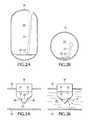
- FIG. 2Aillustrates an example fuel tank maintained in a vertical orientation.
- FIG. 2Billustrates the example fuel tank of FIG. 2A maintained in a horizontal orientation.
- FIG. 3Ais a simplified view of a fuel sensor.
- FIG. 3Billustrates the fuel sensor of FIG. 3A immersed in a liquid.
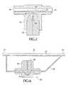
- FIG. 4illustrates a plan view of a sensor housing.
- FIG. 4Aillustrates a first cross-sectional view of the sensor housing.
- FIG. 4Billustrates a second cross sectional view of the sensor housing.
- FIG. 5illustrates a fuel sensor positioned below a reservoir.
- FIG. 6illustrates a fuel sensor located on an auxiliary fuel line.
- FIG. 7illustrates a fuel sensor positioned above a reservoir.
- FIG. 8illustrates an alternate embodiment of a fuel sensor.
- FIG. 9illustrates an algorithm for detecting a low fuel condition.
- FIG. 10illustrates an auxiliary fuel tank system
- FIG. 11illustrates a relationship of vehicle run time estimations, vapor pressure and ambient temperature of a liquid propane fuel system.
- FIG. 11Ais a table illustrating example operating conditions used in the run time estimations of FIG. 11 .
- FIG. 12illustrates a example method of monitoring a low fuel condition.
- FIG. 13illustrates a further embodiment of an auxiliary fuel tank system
- FIG. 1illustrates a low fuel warning system 10 for a motorized vehicle (not shown).
- the low fuel warning system 10may include a liquid draw type liquid propane (LP) fuel system including a fuel sensor 30 that is configured to detect the presence of liquid, vapor, or any phase combination of propane in a pipe, fuel supply line, or container.
- LPliquid draw type liquid propane
- the low fuel warning system 10is illustrated as showing components connected by lines, however these lines are provided for illustrative purposes only, and may be understood to represent fuel lines, electrical connections, or communication between components.
- the low fuel warning system 10may be incorporated in an engine management system that is controlled by an on-board computer, processor or controller 200 .
- the controller 200may receive input from a pressure transducer 16 , a tank temperature sensor 21 , the fuel sensor 30 , and various other components of the engine management system.
- the controller 200may provide input to, or control, a vehicle horn 12 , a low fuel indicator 6 , an engine 15 , etc.
- a pressure switch S 1is shown connected intermediate the fuel sensor 30 and the pressure transducer 16 .
- a sight glass 18may be provided near the fuel tank 20 , for example, to make visible the fuel in the fuel line during testing. Otherwise, the sight glass 18 is not typically provided in the low fuel warning system 10 .
- a sensor output switch S 2is shown intermediate to the fuel sensor 30 and the controller 200 .
- Toggle switch S 3is shown intermediate a horn 12 and the controller 200 .
- An audible alarm 7may provide a warning of a low fuel condition, including a final warning of imminent fuel exhaustion.
- the low fuel indicator 6 and/or the audible alarm 7may be contained in a sensor indicator light box 4 .
- the low fuel indicator 6is shown as including a switch S 4 .
- the low fuel warning system 10may include pressure or temperature sensing switches and sensors which may be configured to trigger additional warnings after the low fuel indicator 6 is first activated, and before the fuel tank 20 runs out of fuel.
- the battery 8may provide power to the horn 12 and the sensor indicator light box 4 , as well as other electrical components in the low fuel warning system 10 , such as the controller 200 .
- a filter/regulator 14is shown connected to the fuel line between the engine 15 and an LP lockoff 13 .
- the fuel tank 20may include a tank heater 27 , that is configured to operate according to changes in ambient temperature, fuel temperature, fuel pressure, fuel level, or various other operating parameters.
- the low fuel warning system 10may include a low fuel indicator 6 (e.g. a light and/or an alarm) to make a vehicle operator aware of a low fuel condition.
- the low fuel warning system 10may utilize the LP lockoff 13 to initiate a low fuel mode of operation to prevent the starter motor operating with no fuel to the engine leading to starter motor overheating and battery 8 discharge and/or to limit engine rpm.
- the multiple restart practiceis a common occurrence in some operations, that otherwise may use the starter motor to get the vehicle to move after the vehicle runs out of LP fuel.
- the fuel sensor 30may incorporate a filtered output signal to prevent a flickering or intermittent notification of the low fuel indicator 6 resulting from an instantaneous vapor reading. This may be accomplished by programmable output signal logic. In one embodiment a microprocessor is incorporated into the fuel sensor 30 , whereas the fuel sensor 30 may be controlled by the controller 200 in some applications or other embodiments.
- the low fuel indicator 6may be provided in a dash display of the vehicle. In one embodiment, an aftermarket configuration vapor sensor based low fuel warning system may be implemented which incorporates it's own warning light and/or audible alarm to ensure functional compatibility on all forklifts or other LP engine powered vehicles or equipment.
- FIG. 2Aillustrates an example fuel tank 20 maintained in a vertical orientation.
- the fuel tank 20may be an exchangeable LP fuel tank including an internal fuel supply tube 22 .
- the low fuel warning system 10 of FIG. 1may take advantage of the liquid fuel 25 under the fuel tank's fuel supply tube inlet 23 , as well as the pressurized propane vapor 24 in the tank 20 , which combine to serve as an internal low fuel reservoir supply.
- This liquid fuel 25may provide a minimal reserve operational time regardless of ambient or operating temperature.
- the LP fuel systemtypically starts running on vapor when the liquid fuel level 25 drops below the fuel supply tube inlet 23 , and the liquid fuel 25 is subsequently converted to propane vapor 24 .
- FIG. 2Billustrates the example fuel tank 20 of FIG. 2A maintained in a horizontal orientation.
- a pool of the liquid fuel 25is shown located beneath the fuel supply tube inlet 23 of the internal fuel supply tube 22 , similarly as described with reference to FIG. 2A .
- the low fuel warning system 10may provide additional low fuel warning time after the liquid fuel 25 is no longer in the fuel line 35 . Fuel from this reservoir of pressurized vapor 24 inside the fuel tank 20 can result in additional low fuel warning time. Warmer weather can increase the tank vapor pressure and result in a longer run time after liquid fuel 25 runs out.
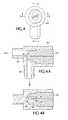
- FIG. 3Ais a simplified view of a fuel sensor 30 .
- the fuel sensor 30includes optic refraction sensor technology.
- the fuel sensor 30is illustrated as being mounted in a fuel line 35 .
- the fuel sensor 30may include an emitter 32 and a receiver 34 , and in one embodiment does not include any moving parts. This may increase reliability of the fuel sensor 30 as well as the low fuel warning system 10 .
- the emitter 32may be configured to transmit a signal 38
- the receivermay be configured to receive or identify the signal 38 .
- the signal 38may form a light path within the fuel sensor, such as within a sensor cone 37 .
- the sensor conemay include one or more lens 36 . When the fuel sensor 30 is immersed in a vapor or gas, the signal 38 is reflected by the lens 36 such that the signal remains inside of the sensor cone 37 , essentially at full strength.
- FIG. 3Billustrates the fuel sensor 30 of FIG. 3A immersed in a liquid such as liquid fuel 25 .
- a liquidsuch as liquid fuel 25 .
- Some of the signal 38may be absorbed by, or refracted into, the liquid fuel 25 that is in contact with the lens 36 , such that the signal 38 that is received by the receiver 34 is less strong as compared to the fuel sensor 30 illustrated in FIG. 3A .
- a refracted signal 39 that is emitted into the liquid fuel 25may therefore not be received by the receiver 34 .
- the receiver 34identifies a liquid, vapor, or combined liquid and vapor (i.e. two phase) state of the LP fuel in the fuel line 35 according to the strength of the received signal 38 .
- the fuel sensor 30may be configured to detect the difference between liquid and vapor propane, in some cases this may result in a flickering indicator light condition due to irregular flow of LP fuel in the fuel line 35 .
- the irregular flow of LP fuelmay result from varying demands of the engine 15 ( FIG. 1 ), for example idle versus full throttle operating conditions, as well as vapor pockets that may form in the fuel line 35 .
- a microprocessor or controllersuch as the controller 200 of FIG. 1 , may be configured to filter the signal 38 via a light activation logic sequence. The light activation logic sequence is illustrated in FIG. 9 , and described in detail, further herein.
- FIG. 4illustrates a plan view of a sensor housing 40 .
- the sensor housingmay be attached to the fuel line 35 ( FIG. 3A , 3 B).
- a first cross section of the sensor housing 40is shown taken with respect to axis A-A and further illustrated in FIG. 4A .
- a second cross section of the sensor housing 40is shown taken with respect to axis B-B and further illustrated in FIG. 4B .
- FIG. 4Aillustrates the first cross-sectional view of the sensor housing 40 including the fuel sensor 30 .
- the housing 40may be attached or connected to the fuel line 35 .
- the housing 40may include or be connected to a first port 44 and a second port 45 of the fuel line 35 .
- the first port 44is configured in an approximately horizontal orientation
- the second port 45is oriented in an approximately vertical orientation.
- the first port 44is an outlet port and the second port 45 is an inlet port.
- FIG. 4Billustrates a second cross sectional view of the sensor housing 40 , including the emitter 32 and the receiver 34 .
- the effective signal path 48 of the fuel sensor 30may identify a path of the signal 38 of FIG. 3A .
- a restrictive gap 46FIG. 4A ) may be provided between the lens 36 and the housing 40 to facilitate contact of any amount of liquid fuel to contact the effective signal path 48 , for example during a low fuel flow situation. By restricting the flow of fuel past a sensitive part of the lens 36 , this helps to avoid generating erroneous vapor signals that may otherwise occur if the lens 36 is instead in contact with vapor. In one embodiment, this can be accomplished by locating the lens 36 close to the housing 40 .
- the restrictive gap 46may be big enough to allow debris to pass through and not cause excess flow restriction to the LP fuel.
- the restrictive gap 46may be small enough to ensure liquid fuel contacts the lens 36 in a low flow situation.
- the restrictive gap 46is approximately 0.05 inches.
- the size of the restrictive gap 46may depend upon the location of the sensor's detection zones or effective signal path 48 . Flattening the tip of the lens 36 and minimizing the housing clearance from the lens surface may provide an ability to further control the amount of fuel flow which goes through this sensitive cross section area. This may allow the fuel to flow past the sides of the lens 36 in regions where the signals 38 or effective signal path 48 exist.
- the restrictive gap 46( FIG. 4A ) or restriction zone located between the sensor housing 40 and the lens 36 results in any residual fuel droplets clearing off from the lens 36 sooner when the fuel supply changes from a liquid to a vapor.
- High velocity propane vaporblows past the lens 36 in this restrictive gap 46 causing the residual fuel droplets to move downstream. This reduces the chance of the fuel sensor 30 producing an erroneous output due to residual liquid fuel droplets remaining on the lens 36 .
- Intermittent fuel flow intervals that can occur during idle conditionscan vary from constant flow out of the fuel tank 20 to no flow for a few seconds depending upon engine size and tank configuration.
- a predictable liquid volumetric siphon effect of a 100% fluid column from the fuel tank 20 to the engine 15may not exist due to the generation of vapor bubbles & vapor pockets within the fuel line 35 .
- the fuel tank 20“burps” out liquid fuel in seemingly random time intervals as described above.
- a sensor sampling time intervalcan be programmed to be a bit longer than the longest “burp” interval for the application.
- the fuel sensor 30is located near or at the vaporizer 110 ( FIG. 10 ) to identify a lower liquid flow.
- the port 44By configuring the port 44 in a substantially horizontal orientation and the port 45 in a substantially vertical orientation, false vapor readings may be avoided. Liquid fuel may be allowed to drain into the port 45 , whereas vapor may be vented around the lens 36 and out the port 44 .
- the location of the emitter 32 and receiver 34may be oriented such that the effective signal path 48 ( FIG. 4B ) resides at the sides of the lens 36 where the maximum flow restriction occurs.
- the effective signal path 48may be located above or below the reservoir 50 .
- the beam planeis approximately perpendicular to the axes of the inlet and outlet ports 45 , 44 . This ensures liquid fuel 25 contacts the sensitive part of the lens 36 instead of bypassing it.
- the housing 40 and sensor lens 36may be arranged such that any liquid droplet would drain out and any vapor bubble would vent instead of being trapped, causing erroneous signals. This may be accomplished by offsetting the downstream port axis from the lens axis. Increasing the bore size of the inlet and outlet ports 45 , 44 may also extend the inner diameter of the fuel line 35 to the edges of the reservoir 50 located between the lens 36 and the housing 40 .
- Liquid fuel flowmay be very low and intermittent during idle conditions. In some cases liquid fuel 25 trickles through the bottom of the fuel line 35 when a large vapor pocket exists in the fuel line 35 . Fuel sensor performance can also be affected by the location of the fuel sensor 30 . Sometimes there are vapor pockets in the higher and more vertical sections of the fuel supply line 35 . Also, the amount of vapor in the fuel may increase near the vaporizer 110 ( FIG. 10 ) or other hot supply line components which cause vapor bubbles to form. In one embodiment, the fuel sensor 30 is located in a low part of the fuel line 35 away from hot supply line components.
- the fuel sensor 30 and housing 40may include a 1 ⁇ 4NPT pipe fitting and/or SAE 45 plumping connection, for example, that can be arranged to be straight or at an angle (e.g. between 45 degrees and 90 degrees).
- the lens 36may provide a predetermined angle of refraction according to the type of fuel, such as LP fuel, that comes into contact with the lens 36 .
- the sensor housing 40may be made of brass, zinc, aluminum or other material which is non-reactive with the fuel.
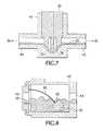
- FIG. 5illustrates the fuel sensor 30 positioned below a reservoir 50 .
- the fuel line 35FIGS. 3A , 3 B or housing 40 may include inlet and outlet ports 44 , 45 .
- the reservoir 50may contain a pool of liquid fuel. This allows the fuel sensor 30 to be in contact with mainly liquid instead of being exposed to fuel mixtures that have more vapor bubbles than liquid fuel.
- the vapor bubble generation in the fuel line 35may be so much greater than the liquid fuel 25 coming from the fuel tank 20 that the resulting two-phase mixture may erroneously generate a vapor signal.
- the denser liquid fuel 25may settle out to the lowest point in the reservoir 50 while the vapor bubbles pass above this pool of liquid fuel 25 .
- the fuel sensor 30may detect the liquid state so that a low fuel warning is not erroneously indicated.
- a higher pressureis required to keep this relatively hotter liquid pool in the reservoir 50 in a liquid state as compared with the system pressure generated by the cooler fuel in the fuel tank 20 .
- the tank temperature and resulting tank pressurestart to drop more rapidly when the fuel system begins to draw vapor instead of liquid from the fuel tank 20 .
- the low fuel indicator 6( FIG. 1 ) may be triggered when the fuel sensor 30 identifies that the fuel in the reservoir 50 or in the fuel line 35 is in the vapor state.
- FIG. 6illustrates a fuel sensor 30 located in an auxiliary fuel line 65 .
- the fuel line 35may be understood as being the main fuel line.
- the auxiliary fuel line 65may be connected to and run at a lower vertical elevation than the fuel line 35 .
- liquid fuel 25 traveling between inlet and outlet ports 74 , 75may be transmitted by the fuel line 35 or the auxiliary fuel line 65 , or both lines 35 , 65 .
- excess fuelmay pass through the fuel line 35 , such that liquid fuel 25 may be transmitted by both fuel lines 35 , 65 .
- the auxiliary fuel line 65may allow the denser liquid fuel 25 to pass by or through the fuel sensor 30 while the less dense vapor bubbles pass through the main fuel line 35 . During low fuel demands, all the liquid fuel 25 may be transmitted via the auxiliary fuel line 65 .
- FIG. 7illustrates the fuel sensor 30 positioned above the reservoir 50 .
- the fuel sensor 30may described as being inverted, as compared with FIG. 5 .
- the housing 40may be configured or constructed so as to provide or include the reservoir 50 .
- the lens 36may be positioned such that it remains immersed in a pool of liquid fuel 25 contained in the reservoir 50 . Vapor bubbles may be allowed to bypass the sensitive portion of the lens 36 , for example in an area of the reservoir 50 that is located above the lens 36 .
- the reservoir 50may therefore enable separation of the fuel vapor bubbles from the liquid fuel 25 .
- first port 44is an outlet port and second port 45 is an inlet port.
- FIG. 8illustrates an alternate embodiment of a fuel sensor 80 attached to a flexible wire 85 .
- the fuel sensor 80may be unaffected by the mounting orientation of the housing 40 to the fuel line, as the flexible wire 85 allows the fuel sensor 80 to move around freely inside the sensor housing 40 .
- the fuel sensor 80settles to the bottom of the sensor housing 40 in order to remain below the surface of the liquid fuel 25 in the reservoir 50 .
- the fuel sensor 80may be configured to operate regardless of the orientation of the housing 40 .
- the inlet and outlet ports 45 , 44may be centered in the ends of the housing 40 so the liquid fuel 25 will pool around the fuel sensor 80 .
- the fuel sensor 80is an electro-optic liquid level sensor attached to the flexible wire 85 .
- FIG. 9illustrates an algorithm including a sensor sampling time interval for detecting a low fuel condition.
- a no-load idle conditionthere may not be a continuous flow of liquid fuel 25 to the vaporizer 110 ( FIG. 10 ), but rather an intermittent flow or two-phase combination of liquid and vapor.
- the primary seat of the LP filter/regulator 14( FIG. 1 ) may cycle open and closed during these conditions, for example once every few seconds, instead of being slightly open all the time.
- the time interval of the liquid fuel discharge cycle from the fuel tank 20may be several seconds (e.g. three to six seconds) with a one to three second liquid discharge duration time.
- the fuel sensor 30 or controller 200may provide for an extended sampling time feature having programmable duration (e.g. five seconds) which effectively accommodates this.
- the sensor sampling time interval featuremay be utilized to minimize excess flickering or sounding of the low fuel indicator 6 ( FIG. 1 ) when the liquid level first starts to fall below the fuel pick-up tube inlet 23 ( FIGS. 2A , 2 B). This feature may also be utilized to command the low fuel indicator 6 to illuminate, sound, remain off, beep or flash after engine start-up.
- An example of the sensor indicator activation logicis shown in FIG. 9 .
- the algorithm illustrated by FIG. 9may be a programmable operation, which may be executed by a microprocessor or controller.
- the sensor sampling time intervalis not initiated. However, if vapor is present, then the sensor sampling time interval is initiated. If liquid fuel becomes present during a five second period, the sensor sampling time interval will reset and will initiate only when vapor is present again. If vapor is continuous for at least five seconds, the low fuel indicator 6 (e.g. LED) will be activated and remain on for five seconds. The next sensor sampling time interval may be initiated when liquid fuel is again detected, and the cycle repeats as described above.
- the low fuel indicator 6e.g. LED
- a minimum latched interval of the low fuel indicator 6may be used to prevent excess flickering. Longer latched periods could reduce the frequency of warning light activation. However shorter intervals may give the operator a better indication of the tank status. For example, if the tank's liquid fuel level is just starting to fall below the pick up tube inlet 23 ( FIGS. 2A , 2 B), the low fuel indicator light activation may be more intermittent. If the operator notices a steady activation of the low fuel indicator 6 , it may indicate that the tank 20 is closer to being empty. In the example shown in FIG. 9 , the low fuel indicator 6 never activates for less than five seconds.
- the low fuel indicator 6is automatically turned off at the end of the five second interval (see for example condition A at time 10 seconds and condition B at 13 seconds).
- Significant two-phase conditions or alternating vapor and liquidmay not activate the low fuel indicator 6 unless the vapor phase is of at least the minimum threshold duration.
- condition C of FIG. 9the low fuel indicator 6 does not activate until the time indicated at 24 seconds.
- the sensor sampling time intervalmay need to be greater than five seconds especially if the fuel sensor 30 is located in a section of the fuel line 35 that has a constant vapor pocket.
- FIG. 10illustrates an auxiliary fuel tank system 100 that may be configured to be self filling.
- the auxiliary fuel tank system 100may include a main fuel tank 115 , as well as the battery 8 and engine 15 , as illustrated in FIG. 1 .
- the main fuel tank 115is understood as being a main fuel tank of a motorized vehicle.
- the main fuel tank 115may operate similarly as the fuel tank 20 of FIG. 1 .
- the main fuel tank 115may be removed from the auxiliary fuel tank system 100 or, more generally, the main fuel tank 115 may be removed from the vehicle associated with the auxiliary fuel system 100 .
- the auxiliary fuel tank system 100further includes an auxiliary fuel tank 120 , vaporizer 110 , and LP injector 114 .
- a pressure switch 126is shown as being connected to the battery 8 , low fuel light 128 and low fuel audible alarm 130 .
- a key switch 112may be provided between the battery 8 and the pressure switch 126 .
- the pressure switch 126may be used to indicate when the system pressure is less than some predetermined threshold value.
- the auxiliary fuel tank 120is illustrated as including end segments 124 , optional engine coolant flow provisions 122 , as well as a relief valve V 5 .
- An auxiliary valve V 1may be provided between the auxiliary fuel tank 120 and the fuel line 35 .
- the auxiliary valve V 1may comprise a low back-pressure lockoff valve, checkoff valve, solenoid, or other type of valve.
- the auxiliary valve V 1allows fuel to go into the auxiliary fuel tank 120 when the auxiliary valve V 1 is open, or in a charged state, or when fuel backflows through the auxiliary valve V 1 when the auxiliary valve V 1 operates as a check valve.
- the auxiliary valve V 1When the auxiliary valve V 1 is closed, or in an uncharged state, fuel may be restricted from going out of the auxiliary fuel tank 120 .
- the auxiliary fuel tank system 100may include a system relief valve V 2 , a coupling valve V 3 , a tank valve V 4 , and lockoff 11 .
- Relief valve V 2may be configured to release any excess pressure that builds up in the fuel line 35 .
- Coupling valve V 3may be configured to control or prohibit fuel from exiting the fuel line 35 , for example, when the main fuel tank 115 is being replaced or is removed.
- Tank valve V 4may be configured to control or prohibit fuel from leaving the main fuel tank 115 into the fuel line 35 .
- Coupling valve V 3may be included as an integral component of the fuel line 35 .
- Lockoff 11may comprise one or more valves that control or shut off a circulation of fuel through the fuel line 35 .
- Lockoff 11may be controlled by the auxiliary fuel tank system 100 .
- Tank valve V 4may be included as an integral component of the main fuel tank 115 , and may be opened or closed during refueling or replacement of the main fuel tank 115 . In one embodiment, tank valve V 4 is manually opened and closed by an operator. Coupling valve V 3 , tank valve V 4 and/or lockoff 11 may be separately operated, or operated together, to control the flow of fuel from the main fuel tank 115 to the fuel line 35 .
- the auxiliary fuel tank 120may include a fuel limiting provision to prevent tank capacity from exceeding more than 80% liquid propane.
- the auxiliary valve V 1may be located at the lowest point in the LP fuel line to ensure that liquid propane enters the auxiliary fuel tank 120 rather than vapor. This configuration may also be configured to accommodate a release of liquid propane from the auxiliary fuel tank 120 .
- the auxiliary fuel tank system 100may be configured for forklifts or other internal combustion powered vehicles that provides a useful amount of reserve fuel after the main fuel tank 115 runs empty.
- the auxiliary fuel tank 120may automatically replenish itself when the main fuel tank 115 is refilled or replaced.
- a propane vapor sensorsuch as the fuel sensor 30 of FIG. 1 , triggers the activation of a tank heater 27 ( FIG. 1 ) or activates the auxiliary fuel tank 120 after sensing a pending low fuel condition.
- the auxiliary fuel tank system 100may be configured to automatically fill the auxiliary fuel tank 120 when the main fuel tank 115 is refilled, or when the main fuel tank 115 is replaced or installed on the motorized vehicle.
- the auxiliary fuel tank 120may be filled after a predetermined period of time from when the main fuel tank 120 is refilled or replaced.
- an empty fuel tankmay be removed from the motorized vehicle when it becomes empty, or nearly empty, and may be replaced with a full, removable fuel tank that contains fuel, such as liquid propane gas.
- Lockoff 11may be closed while the main fuel tank 115 is being replaced, and then reopened to allow the fuel to exit the main fuel tank 115 and then enter the fuel line 35 .
- the motorized vehiclemay continue to operate using fuel from the auxiliary fuel tank 120 , even after the main fuel tank 115 has been removed. This may provide the motorized vehicle time to travel between two different refuelling stations, for example.
- Auxiliary valve V 1may be opened together with lockoff 11 such that at least a portion of the fuel from the main fuel tank 115 that enters the fuel line 35 is further allowed to enter the auxiliary fuel tank 120 .
- auxiliary valve V 1may be closed while lockoff 11 remains open, e.g, during normal operation of the motorized vehicle. Lockoff 11 may remain open as long as there remains a sufficient amount of fuel in the main fuel tank 115 to power the motorized vehicle.
- Auxiliary valve V 1may remain closed as long as there remains a sufficient amount of fuel in the main fuel tank 115 .
- the auxiliary fuel tank system 100may be configured to close the lockoff 11 .
- the auxiliary fuel tank system 100may be configured to open the auxiliary valve V 1 .
- Auxiliary valve V 1may be open while lockoff 11 is closed.
- Auxiliary valve V 1 and lockoff 11may be opened and closed, respectively, at the same time, or in sequence.
- auxiliary valve V 1may be opened to allow fuel from within the auxiliary fuel tank 120 to enter the fuel line 35 , and then lockoff 11 may be closed after auxiliary valve V 1 is opened.
- the auxiliary fuel tank system 100can help ensure that fuel from the auxiliary fuel tank 120 is not allowed to enter the main fuel tank 115 , and that the main fuel tank 115 remains empty during the low fuel operating condition, so that all of the fuel can instead be used to power the engine 15 .
- An empty main fuel tank 115also improves efficiency in fuel usage so that the operator of the motorized vehicle is not returning or exchanging a fuel tank that still contains unused fuel.
- Staging the opening and closing of the valve V 1 and lockoff 11may also help to ensure an adequate supply of fuel in fuel line 35 without starving the engine 15 .
- the timing of opening and closing auxiliary valve V 1 and lockoff 11may be configured to avoid, or minimize the amount of, fuel from the auxiliary fuel tank 120 from entering the main fuel tank 115 .
- lockoff 11may be closed prior to the opening of auxiliary valve V 1 .
- lockoff 11may be closed at substantially the same time that auxiliary valve V 1 is opened.
- the auxiliary valve V 1may comprise a directional control valve that is configured to selectively control the direction of flow of fuel into, or out of, the auxiliary fuel tank 120 .
- auxiliary valve V 1may be configured to allow fuel to enter the auxiliary fuel tank 120 and to restrict any fuel from leaving the auxiliary fuel tank 120 .
- auxiliary valve V 1may be configured to allow fuel to exit the auxiliary fuel tank 120 and enter the fuel line 35 .
- the auxiliary fuel tank system 100may be configured to provide fuel to the engine 15 primarily from the main fuel tank 115 .
- the auxiliary fuel tank system 100may be configured to provide fuel to the engine 15 primarily from the auxiliary fuel tank 120 .
- the flow of fuel both to and from the main fuel tank 115may be prohibited during the low fuel operating condition.
- the auxiliary fuel tank system 100may be configured to open and/or close valve V 1 and lockoff 11 in response to detecting a fuel pressure.
- the fuel pressuremay be detected in the fuel line 35 , in the main fuel tank 115 , in the auxiliary fuel tank 120 , by pressure switch 126 , by a pressure sensor, or by any combination thereof.
- the auxiliary fuel tank system 100may be configured to open and/or close valve V 1 and lockoff 11 in response to detecting a low fuel operating condition using any system, apparatus, or method of detecting the low fuel operating condition, as further described in the present application.
- the auxiliary fuel tank 120is sized for an approximately 15 minute fuel supply.
- the pressure switch 126may be provided with an initial activation pressure of 20 pounds per square inch (psi) or less.
- the low pressure switch 126may be configured to deactivate at a pressure of 30 psi or more.
- the auxiliary valve V 1may be configured to allow fuel into the auxiliary fuel tank 120 when the auxiliary valve V 1 is initially in an uncharged position, e.g., when the main fuel tank 115 is being refilled or replaced.
- the auxiliary valve V 1may be configured to allow fuel from the auxiliary fuel tank 120 to be released into the fuel supply system when the auxiliary valve V 1 is in the electrically charged position, e.g., when the low fuel operating condition is detected.
- the auxiliary fuel tank 120may be tee'd into the fuel line 35 downstream of the main fuel supply lockoff 11 .
- the pressure switch 126may be activated when liquid fuel is boiled off in the main fuel tank 115 and the supply vapor pressure is low.
- the auxiliary valve V 1may be configured to open and release fuel from the auxiliary fuel tank 120 into the fuel line 35 .
- the low fuel warning light 128 and audible alarm 130may be connected to the same circuit as the auxiliary valve V 1 , thus warning the operator of the low fuel condition. This cycle may continue until the auxiliary fuel tank 120 runs out of fuel or until the truck is turned off for refueling.
- the auxiliary fuel tank system 100may be configured to continue providing fuel from the auxiliary fuel tank 120 based on a system check indicating the low fuel operating condition.
- the auxiliary fuel tank 120recharges until it is full. In one embodiment, the auxiliary fuel tank 120 remains full until the pressure switch 126 is activated or the auxiliary valve V 1 is opened.
- the auxiliary fuel tank system 100may be configured to utilize the auxiliary fuel tank 120 to provide additional run time, in response to detecting a low fuel operating condition. In response to detecting a higher pressure associated with a replacement or refilled main tank, the auxiliary fuel tank system 100 may be configured to switch the main fuel tank 115 back into the system. Switching the main fuel tank 115 back into the auxiliary fuel tank system 100 may operate to automatically recharge the auxiliary fuel tank 120 and resupply fuel to the system.
- the auxiliary fuel tank 120may be open to the fuel line 35 while the main fuel tank 115 is disconnected or shut off from the fuel line 35 .
- the tank valve V 4 and interlock 11may be opened to allow fuel from the main fuel tank 115 to flow into the fuel line 35 while the auxiliary fuel tank 120 is still open to the fuel line 35 .
- the auxiliary fuel tank 120may remain open to the fuel line 35 long enough after the main fuel tank 115 is connected to permit recharging of the auxiliary fuel tank 120 .
- the amount of time that the auxiliary fuel tank 120 remains openmay be a time function or a sensed function.
- the auxiliary valve V 1may close after a predetermined period of time once the tank valve V 4 and/or interlock are opened, or after a change in pressure is detected.
- the auxiliary valve V 1may be closed.
- the auxiliary valve V 1may remain closed while the tank valve V 4 and/or interlock 11 remain open.
- the auxiliary fuel tank system 100may be configured to reopen the auxiliary valve V 1 and reconnect the auxiliary fuel tank 120 to the fuel line 35 .
- the interlock 11may be closed while the auxiliary valve V 1 is open. This allows all of the fuel in the main fuel tank 115 to be completely consumed by the engine 15 , such that the main fuel tank 115 is not returned or exchanged with remaining fuel.
- Detecting the low fuel operating condition and switching operation from the main fuel tank 115 to the auxiliary fuel tank 120may provide for additional time for operation of the motorized vehicle and/or time to return the vehicle to exchange or refill the fuel tanks. Detection of the low fuel operating condition using a pressure based detection system may avoid false low fuel signals or warnings due to fuel slosh or fuel tank orientation.
- the auxiliary fuel tank 120auto-refills when a full fuel tank, e.g, main fuel tank 115 , is installed or replaced in the auxiliary fuel tank system 100 . No operator action may be required to switch the installed tanks in and out of the system.
- auxiliary valve V 1 and lockoff 11may be controlled directly by the auxiliary fuel tank system 100 .
- auxiliary valve V 1 and lockoff 11may comprise one or more pressure switches and/or solenoid lock-off valves.
- the auxiliary fuel tank system 100may incorporate temperature compensating pressure switches, to provide detection of a low fuel condition due to pressure changes for vehicles operating in extreme conditions, such as a freezer or cold room, or in environments with large temperature fluctuations.
- the temperature compensated pressure switchesmay be manually adjusted, or self adjusting, depending on the measured temperature(s).
- the temperature compensated pressure switchesmay operate or be adjusted based on fuel temperature or ambient temperature.
- the auxiliary fuel tank 120may be permanently mounted to the motorized vehicle, whereas the main fuel tank 115 may be removable from the motorized vehicle.
- the main fuel tank 115may be removed during a refilling or refueling operation, and then reinstalled on the same or different motorized vehicle in a full condition.
- the main fuel tank 115may completely run out of usable fuel (both liquid and high pressure vapor) when the low fuel operating condition is detected. In one embodiment, only relatively low pressure fuel vapor is left in the main fuel tank 115 when it is exchanged for a new fuel tank.
- the auxiliary fuel tank 120may comprise a sufficient amount of fuel that will allow the vehicle to continue to run long enough to return to the refueling station to refuel and/or change out the main fuel tank 115 .
- the auxiliary fuel tankmay be refilled from the main fuel tank 115 without the use of any pumps or additional sources of pressure or vacuum, except for the pressure provided by the fuel in the main fuel tank 115 .
- no actionis required to be taken by the operator to refill the auxiliary fuel tank 120 when the main fuel tank is being replaced or exchanged.
- the operatormay enable one or more switches to begin filling the auxiliary fuel tank 120 during, or after, refilling or replacing the main fuel tank 115 .
- FIG. 11illustrates a relationship of vehicle run time estimations, vapor pressure and ambient temperature of a liquid propane fuel system.
- the graphdemonstrates how monitoring LP fuel level based on vapor pressure cannot provide a consistent or adequate warning time over a wide temperature span due to the varying propane vapor pressure.
- the fuel reserve systemis instead based on liquid LP instead of propane vapor the effect of temperature on run time would no longer be a significant factor.
- the pressure switch 126( FIG. 10 ) may be set for 32 psi, to provide approximately two minutes of warning. However, longer low fuel warning times via higher pressure switch settings (e.g. 40 psi and 60 psi) can cause the low fuel light to illuminate regardless of liquid fuel level in cold conditions. By way of example, a conventional low fuel warning light will illuminate if temperature is less than ⁇ 38° F. and 60 psi switch is used.
- FIG. 11Ais a table illustrating example operating conditions used in the run time estimations of FIG. 11 .
- the vehicle run time estimations and vapor pressure shown in FIG. 11are temperature dependent.
- the relationship shown in FIG. 11assumes that the tank vapor is at ambient temperature when liquid is below the fuel pickup tube. Once liquid starts boiling off, e.g., when the fuel gets below the fuel pickup tube, the temperature in the fuel tank may drop significantly, and the tank pressure may also drop quickly. Adding a heater, such as heater 27 of FIG. 1 . to the fuel tank may increase vehicle run time.
- the auxiliary fuel tank 120 of FIG. 10provides a predictable low fuel warning period even during cold weather operation. It may increase the low fuel warning/operation time which allows an operator to complete a task before returning to the refill station. It may also allow the main fuel tank 115 to be completely emptied so no unused fuel is wasted when fuel tanks are exchanged.
- the audible alarm 130( FIG. 10 ) may be incorporated to complement a low fuel warning light 128 to ensure the operator is aware of a low fuel condition.
- the auxiliary fuel tank 120provides for a longer LP low fuel warning time which allows equipment operators adequate time to finish a job (i.e. a forklift emptying a delivery truck, etc.) and return to the fuel tank exchange station or refueling station before the engine dies. Fuel cost savings may be achieved by running the LP fuel exchange tanks until nearly empty instead of returning fuel tanks that are partially full. Productivity may be improved since equipment can be operated longer and with fewer tank changes as compared to methods where the tank is changed out prematurely (based on operator's rough estimates of remaining fuel). Cost savings may be realized by avoiding down time and extra labor associated with arranging to exchange fuel tanks on trucks that run out of fuel away from the refueling station.
- Engine performance of an LP fueled vehiclecan be limited based on a low fuel signal and a timer.
- a vehicle performance limitation systemit may encourage operators not to ignore the low fuel warning (which may be done via engine performance limitation) and instead prompt the operator to refuel the fuel tank 20 ( FIG. 1 ) or the main fuel tank 115 ( FIG. 10 ).
- An indicator light or alarmsuch as the low fuel indicator 6 ( FIG. 1 ) or 128 ( FIG. 10 ), may indicate a low fuel condition.
- the sensorsuch as the fuel sensor 30 ( FIG. 1 ) looks for a five second steady vapor signal.
- the low fuel indicator 6remains off until the fuel sensor 30 detects steady vapor for five seconds.
- the fuel sensor 30will look for a five second steady vapor condition again. If steady, the low fuel indicator 6 remains on and this cycle repeats. If not, the low fuel indicator 6 goes out.
- the engine performancemay be limited to a first engine speed.
- the first engine speedmay be set at 1800 revolutions per minute (RPM).
- the low fuel indicator 6is commanded to flash or sound on and off at alternating one second intervals.
- the engine performancemay be limited to a second engine speed less than the first.
- the second engine speedmay be set at a maximum value of 1200 RPM.
- the low fuel indicator 6may be commanded to flash or sound on and off at alternating one half second intervals. Engine speeds and time intervals may be programmable.
- the low fuel indicator 6may be provided in a vehicle dash, or provided as part of an aftermarket system. It may also be used for activating an audible alarm on Aftermarket or Original Equipment Manufacturer (OEM) systems.
- OEMOriginal Equipment Manufacturer
- the system memorymay accommodate restart at the timing cycle where it stopped. The cycle may be reset if the fuel sensor 30 no longer provides a steady signal, such as when the fuel tank 20 is being refueled. If the vehicle was shut down during either of the five minute or ten minute intervals, upon restart, the system may wait for short period of time (e.g. seven seconds) before looking for a low fuel input signal. If a low fuel signal occurs within seven seconds after start up, the system timer may need to start at the same place it was stopped. If not, the entire cycle may be repeated.
- short period of timee.g. seven seconds
- the engine performancemay be reduced by 50% after some period of time (e.g. five minutes) after a low fuel warning condition is identified.
- An idle performance (creep speed) of the enginemay be commanded some ten minutes after a low fuel warning condition was identified. This encourages the operator to go refuel the truck before the engine stalls due to lack of fuel.
- the vehicle performance limitation systemmay be configured to pick up engine speed via inductance from a spark plug wire and control a valve in the fuel line 35 that is either plumbed into the system or integrated into the fuel sensor 30 itself. Since this valve is only operational during the vapor mode, engine speed control problems associated with liquid fuel droplets boiling off vapor in an uncontrolled fashion are eliminated.
- FIG. 12illustrates a example method of monitoring a low fuel condition in a motorized vehicle.
- the methodmay be performed by a microprocessor, computer, processor or the controller 200 shown in FIG. 1 .
- signalsare received from a fuel sensor, such as fuel sensor 30 of FIG. 1 .
- the signalsmay indicate the presence of a vapor, a liquid, or a two-phase combination of vapor and liquid in a fuel line.
- the number of signals received from the fuel sensor 30is determined.
- the number of signalsmay be used by an algorithm, as described with respect to FIG. 9 for example, and including a sensor sampling time interval.
- the low fuel conditionis identified when the number of received signals exceeds a threshold value. In one embodiment, the low fuel condition is identified when a number of signals is received that correspond to a five second period of time.
- a vehicle operatoris alerted to the low fuel condition.
- the operatormay be alerted via a low fuel indicator light or audible alarm.
- a low fuel mode of operation of the motorized vehicleis commanded.
- the low fuel conditionmay indicate the presence of a fuel vapor in a fuel line.
- a low fuel control valvemay operate to control the fuel vapor only during the low fuel mode of operation.
- an engine speed of the motorized vehicleis restricted to a maximum operational value in the low fuel mode of operation.
- an engine starteris disabled when the low fuel mode of operation is completed.
- the weight of the fuel tank 20 mounted to an industrial vehicleis compared to the weight of an empty fuel tank in order to determine the amount of remaining fuel in the fuel tank 20 .
- the weightmay be determined by a sensor, for example.
- a low fuel conditionmay be identified when weight of the fuel tank 20 approaches the weight of an empty fuel tank.
- a temperature differential between a liquid and gaseous (ambient) section of the fuel tank 20is measured to determine a fuel level.
- an upper sensor, or first thermistormay be located near the top of the fuel tank 20
- a lower sensor, or second thermistormay be located near the bottom of the fuel tank 20 .
- the lower sensoris located at approximately 10% of the full tank level.
- the two sensorsmay be attached to a tank clamp.
- a low fuel conditionmay be identified when the temperature differential approaches zero or some other threshold value, or when the upper and lower sensors detect the same value.
- the fuel sensor 30 , 80may be used for other types of fuel besides propane. Other fuel sensor types and vapor/liquid detection systems and methods may be used with the systems and method described herein.
- the sensorsmay include: ultrasonic, acoustic, catalytic, thermal, optical, infrared, photoelectric, electrochemical, mechanical, tank temperature differential, semiconductor, vibrating, di-electric constant, and flow velocity comparisons of the fuel.
- FIG. 13illustrates a further embodiment of an auxiliary fuel tank system 300 .
- Fuel line 335includes a first end 310 configured to receive fuel from a fuel tank, such as fuel tank 20 ( FIG. 1 ) or main fuel tank 120 ( FIG. 10 ), and a second end 330 configured to transmit fuel to an engine, such as engine 15 ( FIG. 10 ).
- Auxiliary fuel tank 320may contain one or both of liquid fuel 350 and vapor fuel 340 .
- the liquid fuel 350may comprise liquid propane gas.
- the auxiliary fuel tank 320may be configured to store no more than 80% liquid fuel by volume, or as determined by regulation or engineering standards, to provide an expansion area, e.g., 20% by volume.
- a vent line 365may be configured to maintain a predetermined ratio of the liquid fuel 350 and vapor fuel 340 within the auxiliary fuel tank 320 .
- a first valve 360may be configured to receive fuel from the fuel line 335 .
- First valve 360may provide means of filling the auxiliary fuel tank 320 .
- the first valve 360may allow fuel to flow to the auxiliary fuel tank 320 when it is activated.
- the first valve 360acts as a one way check valve when the first valve is not activated.
- the first valve 360may allow fuel to enter the auxiliary fuel tank 320 anytime it was not full.
- a reduced pressure differential or back pressure, e.g., less than 20 psi, associated with first valve 360may facilitate refilling of the auxiliary fuel tank 320 .
- First valve 360may be electrically actuated.
- first valve 360may be activated based on a detected system pressure, on a time control, or be manually activated.
- the auxiliary fuel tank 320may comprise a second valve 390 positioned at or near the bottom end of the auxiliary fuel tank 320 . Providing the second valve 390 on the bottom of the auxiliary fuel tank 320 may promote better fuel flow to the engine.
- the second valve 390may be configured to allow fuel from within the auxiliary fuel tank 320 to enter the fuel line 335 via auxiliary fuel line 395 .
- both of the first and second valves 360 and 390may be opened at the same time while the auxiliary fuel tank 320 is being filled.
- the auxiliary fuel tank 320may be filled during operation of the vehicle for some period of time, e.g., a number of minutes, after a refueling operation is completed, or during the refueling operation.
- Accumulators and/or mechanical float valvesmay be configured to shut off one or more of the first and second valves 360 , 390 once the liquid fuel 350 reaches a predetermined level.
- the system and apparatus described abovecan use dedicated processor systems, micro controllers, programmable logic devices, or microprocessors that perform some or all of the operations. Some of the operations described above may be implemented in software and other operations may be implemented in hardware.
Landscapes
- Engineering & Computer Science (AREA)
- Chemical & Material Sciences (AREA)
- Mechanical Engineering (AREA)
- Combustion & Propulsion (AREA)
- General Engineering & Computer Science (AREA)
- Chemical Kinetics & Catalysis (AREA)
- Oil, Petroleum & Natural Gas (AREA)
- General Chemical & Material Sciences (AREA)
- Human Computer Interaction (AREA)
- Life Sciences & Earth Sciences (AREA)
- Sustainable Development (AREA)
- Sustainable Energy (AREA)
- Transportation (AREA)
- Cooling, Air Intake And Gas Exhaust, And Fuel Tank Arrangements In Propulsion Units (AREA)
Abstract
Description
Claims (12)
Priority Applications (1)
| Application Number | Priority Date | Filing Date | Title |
|---|---|---|---|
| US13/074,988US9000905B2 (en) | 2006-08-21 | 2011-03-29 | Auxiliary fuel tank |
Applications Claiming Priority (3)
| Application Number | Priority Date | Filing Date | Title |
|---|---|---|---|
| US83921306P | 2006-08-21 | 2006-08-21 | |
| US11/842,923US7940165B1 (en) | 2006-08-21 | 2007-08-21 | Low fuel warning systems for a motorized vehicle |
| US13/074,988US9000905B2 (en) | 2006-08-21 | 2011-03-29 | Auxiliary fuel tank |
Related Parent Applications (1)
| Application Number | Title | Priority Date | Filing Date |
|---|---|---|---|
| US11/842,923Continuation-In-PartUS7940165B1 (en) | 2006-08-21 | 2007-08-21 | Low fuel warning systems for a motorized vehicle |
Publications (2)
| Publication Number | Publication Date |
|---|---|
| US20110226362A1 US20110226362A1 (en) | 2011-09-22 |
| US9000905B2true US9000905B2 (en) | 2015-04-07 |
Family
ID=44646259
Family Applications (1)
| Application Number | Title | Priority Date | Filing Date |
|---|---|---|---|
| US13/074,988Expired - Fee RelatedUS9000905B2 (en) | 2006-08-21 | 2011-03-29 | Auxiliary fuel tank |
Country Status (1)
| Country | Link |
|---|---|
| US (1) | US9000905B2 (en) |
Cited By (3)
| Publication number | Priority date | Publication date | Assignee | Title |
|---|---|---|---|---|
| US20160356699A1 (en)* | 2014-02-10 | 2016-12-08 | Mechtronic Ltd | Apparatus for Determining Identity and/or Quantity of a Fuel |
| US11230185B2 (en) | 2019-10-01 | 2022-01-25 | S & J 17, Llc | Reserve fuel system |
| US20240116745A1 (en)* | 2022-10-07 | 2024-04-11 | Ford Global Technologies, Llc | Intelligent liquid level display for auxiliary tanks |
Families Citing this family (7)
| Publication number | Priority date | Publication date | Assignee | Title |
|---|---|---|---|---|
| US9000905B2 (en)* | 2006-08-21 | 2015-04-07 | Nmhg Oregon, Llc | Auxiliary fuel tank |
| US8827000B2 (en)* | 2012-03-30 | 2014-09-09 | Deere & Company | Aerator with low fuel level control |
| EP3081800B1 (en)* | 2015-04-13 | 2019-06-05 | IVECO S.p.A. | Fuel withdrawing system from a reservoir of compressed natural gas to supply an internal combustion engine |
| US20160333842A1 (en)* | 2015-05-13 | 2016-11-17 | Caterpillar Inc. | Priming system for gaseous fuel powered engines |
| US9914414B2 (en)* | 2016-06-28 | 2018-03-13 | GM Global Technology Operations LLC | Fluid level indication for vehicle reservoirs |
| KR101745272B1 (en)* | 2016-07-27 | 2017-06-08 | 현대자동차주식회사 | System for filling lpg of lpg vehicle using auxiliary bombe |
| CH716217A1 (en)* | 2019-05-22 | 2020-11-30 | Liebherr Machines Bulle Sa | Pressure tank system for the provision of gases. |
Citations (94)
| Publication number | Priority date | Publication date | Assignee | Title |
|---|---|---|---|---|
| US2807976A (en) | 1955-10-11 | 1957-10-01 | Electron Machine Corp | Refractometer |
| US2811128A (en) | 1955-03-31 | 1957-10-29 | Imp Brass Mfg Co | Liquid indicator for tubing |
| US3710809A (en)* | 1971-01-21 | 1973-01-16 | Fueltime Saver Corp | Reserve fuel system for liquefied gas powered engines |
| US3766395A (en) | 1971-12-27 | 1973-10-16 | Texas Instruments Inc | Fluid level detection system |
| US3832900A (en) | 1971-06-28 | 1974-09-03 | Sperry Rand Corp | Apparatus and method for measuring the level of a contained liquid |
| US3926230A (en) | 1974-06-12 | 1975-12-16 | Marvin L Stary | Recovery of flammable vapors |
| US3949360A (en) | 1974-07-23 | 1976-04-06 | Richard Pignata | Oil level detector and indicator |
| US4037967A (en) | 1973-05-14 | 1977-07-26 | Vdo Adolf Schindling Ag | Apparatus for measuring the density of a liquid, utilizing the law of refraction |
| US4084547A (en) | 1976-03-24 | 1978-04-18 | Honeywell Inc. | Safe start checking liquid processing system |
| US4167002A (en) | 1978-03-10 | 1979-09-04 | N. B. F. Company, Inc. | Low fuel indicating device |
| US4167874A (en) | 1978-05-26 | 1979-09-18 | Sundstrand Corporation | Liquid volume measuring device |
| US4245290A (en) | 1978-12-18 | 1981-01-13 | United Technologies Corporation | Sliding notch pulse width modulation (PWM) |
| US4250750A (en) | 1979-10-09 | 1981-02-17 | Ford Motor Company | Liquid level measuring system |
| US4292620A (en) | 1979-06-13 | 1981-09-29 | Pagane Warren H | Fuel level monitoring engine control and vehicle theft inhibiting device |
| US4306805A (en) | 1979-06-04 | 1981-12-22 | Arrington James R | Refractometric device |
| US4372165A (en) | 1979-09-11 | 1983-02-08 | Itt Industries, Inc. | Apparatus for measuring fluid flow |
| US4402048A (en) | 1980-05-03 | 1983-08-30 | Toyota Jidosha Kogyo Kabushiki Kaisha | Method of and apparatus for indicating remaining fuel quantity for vehicles |
| US4424676A (en)* | 1979-09-12 | 1984-01-10 | M & W Gear Company | Supplementary fuel injection system for a turbocharged internal combustion engine |
| US4427293A (en) | 1980-09-18 | 1984-01-24 | Battelle Memorial Institute | Double optical probe device for the determination of the refractive index of a liquid reduced to a predetermined reference temperature |
| US4437162A (en) | 1980-04-14 | 1984-03-13 | Nissan Motor Company, Limited | Residual liquid meter using computer responsive to measurements of liquid level and flow |
| US4589281A (en) | 1984-09-20 | 1986-05-20 | Keystone International, Inc. | Material level detector and control |
| US4699511A (en) | 1985-04-03 | 1987-10-13 | Seaver George A | Refraction sensor |
| US4734682A (en) | 1986-06-27 | 1988-03-29 | Bond Jr Charles R | Low fluid level warning system |
| US4773260A (en) | 1986-06-23 | 1988-09-27 | Nissan Motor Company, Ltd. | Fuel-level detecting system for automotive vehicle |
| US4811601A (en) | 1983-10-11 | 1989-03-14 | Tolan Peter J | Method and apparatus for measuring the change in volume with change in temperature of liquid in tanks |
| US4907878A (en) | 1985-11-27 | 1990-03-13 | Electricite De France | Device for discriminating fluids having different refractive indices and device for measuring the voluminal fraction of at least one fluid of a current of non-mixible fluids incorporating the discrimination device |
| US4923152A (en)* | 1985-08-05 | 1990-05-08 | Gerard Barkats | Two-liquid propulsive system for an artificial satellite and utilization of said system for ejecting the satellite |
| US4932609A (en)* | 1989-02-27 | 1990-06-12 | United Technologies Corporation | Fuel transfer system for aircraft |
| US5010868A (en) | 1990-04-03 | 1991-04-30 | Jerry Clements | Gas-phase propane fuel delivery system |
| US5083018A (en) | 1990-07-11 | 1992-01-21 | Motorola, Inc. | Fluid index of refraction sensor |
| US5103672A (en) | 1990-09-26 | 1992-04-14 | Ragen Data Systems, Inc. | Flexible transmitter and fluid level gauging probe |
| US5159313A (en) | 1989-06-19 | 1992-10-27 | Toyota Jidosha Kabushiki Kaisha | Oil supply system in an internal combustion engine for a vehicle |
| US5203367A (en)* | 1991-05-29 | 1993-04-20 | Shikoku Kakoki Co., Ltd. | Apparatus for supplying liquid under constant pressure |
| US5275189A (en)* | 1991-12-16 | 1994-01-04 | Ensign Petroleum Equipment Company, Inc. | System for dispensing a fuel mixture |
| US5309760A (en)* | 1988-07-07 | 1994-05-10 | Kanto Seiki Co., Ltd. | Method and apparatus for measuring the content of a storage vessel |
| US5335638A (en)* | 1992-12-28 | 1994-08-09 | Suzuki Motor Corporation | Evaporated fuel controller |
| US5357241A (en) | 1991-08-02 | 1994-10-18 | Welch Jr James G | Fail-safe leak detector |
| US5386111A (en) | 1993-10-08 | 1995-01-31 | Zimmerman; H. Allen | Optical detection of water droplets using light refraction with a mask to prevent detection of unrefracted light |
| US5411058A (en)* | 1992-12-22 | 1995-05-02 | Welsh; James W. | Method and apparatus for utilizing gaseous and liquid fuels in an internal combustion device |
| US5431142A (en)* | 1993-02-18 | 1995-07-11 | Robert Bosch Gmbh | Fuel injection system for internal combustion engines |
| US5452076A (en) | 1993-09-29 | 1995-09-19 | Optiguard, Inc. | Fluid detection system |
| US5563584A (en) | 1993-11-15 | 1996-10-08 | The Johns Hopkins University | Liquid level sensing and monitoring system for medical fluid infusion systems |
| US5595163A (en) | 1995-06-06 | 1997-01-21 | Hitachi America, Ltd. | Apparatus and method for controlling the fuel supply of a gas-fueled engine |
| US5623252A (en) | 1995-05-22 | 1997-04-22 | Cacciola; John A. | Liquid level detector using audio frequencies |
| US5670831A (en) | 1994-12-13 | 1997-09-23 | Georgiades; Demetrios | Vehicle ignition system capable of continued engine running after removal of ignition key |
| US5718260A (en)* | 1995-08-23 | 1998-02-17 | Leonardi; Anthony | Fuel transfer apparatus |
| US5780729A (en)* | 1996-07-24 | 1998-07-14 | The United States Of America As Represented By The Secretary Of The Navy | Fuel delivery system |
| US5831536A (en) | 1996-02-22 | 1998-11-03 | Ray Zager & Company | Fuel tank alarm system |
| US5867089A (en) | 1996-09-03 | 1999-02-02 | Chrysler Corporation | Base-to-remotely controlled vehicle communications for automated durability road (ADR) facility |
| US5881207A (en) | 1995-10-31 | 1999-03-09 | Seb Sa | Steam generator with automatic supply and a process for measuring the level of liquid in such a generator |
| US5886625A (en) | 1997-02-25 | 1999-03-23 | Honda Giken Kogyo Kabushiki Kaisha | Residual fuel amount-estimating system for fuel tank of internal combustion engine |
| US5887479A (en) | 1996-12-31 | 1999-03-30 | Stmicroelectronics, Inc. | Liquid-level gauge driver circuit |
| US5942980A (en) | 1997-11-20 | 1999-08-24 | Innovative Measurement Methods, Inc. | Multi-sensor hydrostatic gauge for fuel storage tanks |
| US5975574A (en)* | 1998-06-24 | 1999-11-02 | Spare Tank Co., Inc. | Auxiliary propane fuel tank system for vehicles |
| US6002328A (en) | 1996-03-15 | 1999-12-14 | Vdo Adolf Schindling Ag | Tank display system and method for determining the remaining volume in a tank |
| US6102065A (en)* | 1999-02-03 | 2000-08-15 | Tobias; Stewart W. | Liquid propane delivery system |
| US6109225A (en) | 1998-01-30 | 2000-08-29 | Toyota Jidosha Kabushiki Kaisha | Valve timing control device for an internal combustion engine |
| US6124794A (en) | 1998-02-17 | 2000-09-26 | Ecolab Inc. | Empty product detector |
| US6134896A (en)* | 1999-03-19 | 2000-10-24 | Spx Corporation | Background tank fill |
| US6192742B1 (en)* | 1997-11-17 | 2001-02-27 | Denso Corporation | More reliable leakage diagnosis for evaporated gas purge system |
| US6252499B1 (en) | 1998-07-29 | 2001-06-26 | Volkswagen Ag | Fuel supply indicator arrangement for a motor vehicle fuel tank |
| US6263902B1 (en)* | 2000-06-26 | 2001-07-24 | Wayne A. Booth | Tank for gaseous fuels with additional internal reservoir |
| US6314947B1 (en) | 1999-10-13 | 2001-11-13 | Walbro Corporation | Fuel delivery system |
| US6408692B1 (en) | 1997-11-20 | 2002-06-25 | Isspro, Inc. | Liquid level sensor |
| US20020118025A1 (en) | 2001-02-26 | 2002-08-29 | Junichi Yamagishi | Piping fluid decision device and piping fluid control system |
| US20030020494A1 (en) | 2001-05-17 | 2003-01-30 | Isabelle Desmier | Fuel sensor |
| US6532813B1 (en) | 1999-09-04 | 2003-03-18 | Mannesmann Vdo Ag | Method and device for determining a fill level of liquid in a container |
| US6557401B2 (en)* | 2000-04-11 | 2003-05-06 | Toyota Jidosha Kabushiki Kaisha | Method and apparatus for detecting abnormalities in fuel systems |
| US20030170075A1 (en) | 1998-06-02 | 2003-09-11 | Strassman David R. | Asphalt heater |
| US6668645B1 (en) | 2002-06-18 | 2003-12-30 | Ti Group Automotive Systems, L.L.C. | Optical fuel level sensor |
| US20040069694A1 (en) | 2002-10-10 | 2004-04-15 | Gamble Paul A. | Fuel system including a water sensor, and a method of installing the water sensor in the fuel system |
| US6766269B2 (en) | 2002-05-20 | 2004-07-20 | Hyundai Motor Company | LPG fuel composition estimation method and system |
| US20040164618A1 (en)* | 2003-02-10 | 2004-08-26 | Bryde Jan Henrik | Fuel control system and method for distributed power generation, conversion, and storage system |
| US6789420B2 (en) | 2001-10-19 | 2004-09-14 | Ark-Les Corporation | Oil flow sensing |
| US6819250B2 (en) | 2001-12-20 | 2004-11-16 | Johnsondiversey, Inc. | Out-of-liquid sensor, and liquid supply device using same |
| US20050040958A1 (en) | 2003-08-20 | 2005-02-24 | Holzman Louis M. | Capacitive sensing monitor and method therefore |
| US6889940B1 (en) | 2004-01-29 | 2005-05-10 | The Boeing Company | Auxiliary fuel tank systems for aircraft and methods for their manufacture and use |
| US20050166972A1 (en) | 2004-02-02 | 2005-08-04 | Michael Casier | System for supplying liquefied gas to a combustion engine with a minimum liquefied-gas level detector |
| US20050217368A1 (en)* | 2003-02-27 | 2005-10-06 | Eiji Akahane | System for measuring quantity of liquid fuel and method for measuring quantity of liquid fuel |
| US20060000279A1 (en) | 2004-07-01 | 2006-01-05 | Jamnia Mohammad A | Device employing magnetic flux to measure the level of fluid in a tank |
| US20060024552A1 (en)* | 2004-07-29 | 2006-02-02 | Sanyo Electric Co., Ltd. | Fuel cell system |
| US7117904B2 (en) | 2003-04-17 | 2006-10-10 | Bayerische Motoren Werke Ag | Device for measuring the level of a fuel tank |
| US7182073B1 (en)* | 2005-08-30 | 2007-02-27 | Hyundai Motor Company | LPI engine system |
| US7195055B1 (en) | 2003-06-16 | 2007-03-27 | Brunswick Corporation | Device for connecting a secondary heat exchanger to an engine cooling system |
| US7199388B2 (en) | 2001-06-12 | 2007-04-03 | Naoyuki Omatoi | Liquid level detecting device |
| US20070157908A1 (en) | 2006-01-11 | 2007-07-12 | Denso Corporation | Fuel vapor treatment apparatus, system having the same, method for operating the same |
| US20070234796A1 (en) | 2006-02-14 | 2007-10-11 | Tshishiku Eugene M | Liquid level detector |
| US20070248854A1 (en)* | 2006-03-30 | 2007-10-25 | Casio Computer Co., Ltd. | Power generation module, system, and method for driving the power generation module |
| US20080218363A1 (en) | 2007-03-08 | 2008-09-11 | Fahed Al Howayshell | Electric generator protection system |
| US20090036248A1 (en) | 2006-03-13 | 2009-02-05 | Bosch Rexroth Ag | Drive with a torque split transmission |
| US7665479B2 (en) | 2005-06-10 | 2010-02-23 | The Boeing Company | Aerial refueling system |
| US7720592B2 (en)* | 2008-05-20 | 2010-05-18 | Ford Global Technologies, Llc | Approach for enhancing emissions control device warmup in a direct injection engine system |
| US7940165B1 (en)* | 2006-08-21 | 2011-05-10 | Nmhg Oregon, Llc | Low fuel warning systems for a motorized vehicle |
| US20110226362A1 (en)* | 2006-08-21 | 2011-09-22 | Nmhg Oregon, Llc | Auxiliary fuel tank |
Family Cites Families (1)
| Publication number | Priority date | Publication date | Assignee | Title |
|---|---|---|---|---|
| US6881207B1 (en)* | 1987-09-08 | 2005-04-19 | Rhonda Tracy | Disposable diaper with padded waistband and legholes |
- 2011
- 2011-03-29USUS13/074,988patent/US9000905B2/ennot_activeExpired - Fee Related
Patent Citations (98)
| Publication number | Priority date | Publication date | Assignee | Title |
|---|---|---|---|---|
| US2811128A (en) | 1955-03-31 | 1957-10-29 | Imp Brass Mfg Co | Liquid indicator for tubing |
| US2807976A (en) | 1955-10-11 | 1957-10-01 | Electron Machine Corp | Refractometer |
| US3710809A (en)* | 1971-01-21 | 1973-01-16 | Fueltime Saver Corp | Reserve fuel system for liquefied gas powered engines |
| US3832900A (en) | 1971-06-28 | 1974-09-03 | Sperry Rand Corp | Apparatus and method for measuring the level of a contained liquid |
| US3766395A (en) | 1971-12-27 | 1973-10-16 | Texas Instruments Inc | Fluid level detection system |
| US4037967A (en) | 1973-05-14 | 1977-07-26 | Vdo Adolf Schindling Ag | Apparatus for measuring the density of a liquid, utilizing the law of refraction |
| US3926230A (en) | 1974-06-12 | 1975-12-16 | Marvin L Stary | Recovery of flammable vapors |
| US3949360A (en) | 1974-07-23 | 1976-04-06 | Richard Pignata | Oil level detector and indicator |
| US4084547A (en) | 1976-03-24 | 1978-04-18 | Honeywell Inc. | Safe start checking liquid processing system |
| US4167002A (en) | 1978-03-10 | 1979-09-04 | N. B. F. Company, Inc. | Low fuel indicating device |
| US4167874A (en) | 1978-05-26 | 1979-09-18 | Sundstrand Corporation | Liquid volume measuring device |
| US4245290A (en) | 1978-12-18 | 1981-01-13 | United Technologies Corporation | Sliding notch pulse width modulation (PWM) |
| US4306805A (en) | 1979-06-04 | 1981-12-22 | Arrington James R | Refractometric device |
| US4292620A (en) | 1979-06-13 | 1981-09-29 | Pagane Warren H | Fuel level monitoring engine control and vehicle theft inhibiting device |
| US4372165A (en) | 1979-09-11 | 1983-02-08 | Itt Industries, Inc. | Apparatus for measuring fluid flow |
| US4424676A (en)* | 1979-09-12 | 1984-01-10 | M & W Gear Company | Supplementary fuel injection system for a turbocharged internal combustion engine |
| US4250750A (en) | 1979-10-09 | 1981-02-17 | Ford Motor Company | Liquid level measuring system |
| US4437162A (en) | 1980-04-14 | 1984-03-13 | Nissan Motor Company, Limited | Residual liquid meter using computer responsive to measurements of liquid level and flow |
| US4402048A (en) | 1980-05-03 | 1983-08-30 | Toyota Jidosha Kogyo Kabushiki Kaisha | Method of and apparatus for indicating remaining fuel quantity for vehicles |
| US4427293A (en) | 1980-09-18 | 1984-01-24 | Battelle Memorial Institute | Double optical probe device for the determination of the refractive index of a liquid reduced to a predetermined reference temperature |
| US4811601A (en) | 1983-10-11 | 1989-03-14 | Tolan Peter J | Method and apparatus for measuring the change in volume with change in temperature of liquid in tanks |
| US4589281A (en) | 1984-09-20 | 1986-05-20 | Keystone International, Inc. | Material level detector and control |
| US4699511A (en) | 1985-04-03 | 1987-10-13 | Seaver George A | Refraction sensor |
| US4923152A (en)* | 1985-08-05 | 1990-05-08 | Gerard Barkats | Two-liquid propulsive system for an artificial satellite and utilization of said system for ejecting the satellite |
| US4907878A (en) | 1985-11-27 | 1990-03-13 | Electricite De France | Device for discriminating fluids having different refractive indices and device for measuring the voluminal fraction of at least one fluid of a current of non-mixible fluids incorporating the discrimination device |
| US4773260A (en) | 1986-06-23 | 1988-09-27 | Nissan Motor Company, Ltd. | Fuel-level detecting system for automotive vehicle |
| US4734682A (en) | 1986-06-27 | 1988-03-29 | Bond Jr Charles R | Low fluid level warning system |
| US5309760A (en)* | 1988-07-07 | 1994-05-10 | Kanto Seiki Co., Ltd. | Method and apparatus for measuring the content of a storage vessel |
| US4932609A (en)* | 1989-02-27 | 1990-06-12 | United Technologies Corporation | Fuel transfer system for aircraft |
| US5159313A (en) | 1989-06-19 | 1992-10-27 | Toyota Jidosha Kabushiki Kaisha | Oil supply system in an internal combustion engine for a vehicle |
| US5010868A (en) | 1990-04-03 | 1991-04-30 | Jerry Clements | Gas-phase propane fuel delivery system |
| US5083018A (en) | 1990-07-11 | 1992-01-21 | Motorola, Inc. | Fluid index of refraction sensor |
| US5103672A (en) | 1990-09-26 | 1992-04-14 | Ragen Data Systems, Inc. | Flexible transmitter and fluid level gauging probe |
| US5203367A (en)* | 1991-05-29 | 1993-04-20 | Shikoku Kakoki Co., Ltd. | Apparatus for supplying liquid under constant pressure |
| US5357241A (en) | 1991-08-02 | 1994-10-18 | Welch Jr James G | Fail-safe leak detector |
| US5275189A (en)* | 1991-12-16 | 1994-01-04 | Ensign Petroleum Equipment Company, Inc. | System for dispensing a fuel mixture |
| US5411058A (en)* | 1992-12-22 | 1995-05-02 | Welsh; James W. | Method and apparatus for utilizing gaseous and liquid fuels in an internal combustion device |
| US5335638A (en)* | 1992-12-28 | 1994-08-09 | Suzuki Motor Corporation | Evaporated fuel controller |
| US5431142A (en)* | 1993-02-18 | 1995-07-11 | Robert Bosch Gmbh | Fuel injection system for internal combustion engines |
| US5452076A (en) | 1993-09-29 | 1995-09-19 | Optiguard, Inc. | Fluid detection system |
| US5386111A (en) | 1993-10-08 | 1995-01-31 | Zimmerman; H. Allen | Optical detection of water droplets using light refraction with a mask to prevent detection of unrefracted light |
| US5563584A (en) | 1993-11-15 | 1996-10-08 | The Johns Hopkins University | Liquid level sensing and monitoring system for medical fluid infusion systems |
| US5670831A (en) | 1994-12-13 | 1997-09-23 | Georgiades; Demetrios | Vehicle ignition system capable of continued engine running after removal of ignition key |
| US5623252A (en) | 1995-05-22 | 1997-04-22 | Cacciola; John A. | Liquid level detector using audio frequencies |
| US5595163A (en) | 1995-06-06 | 1997-01-21 | Hitachi America, Ltd. | Apparatus and method for controlling the fuel supply of a gas-fueled engine |
| US5718260A (en)* | 1995-08-23 | 1998-02-17 | Leonardi; Anthony | Fuel transfer apparatus |
| US5881207A (en) | 1995-10-31 | 1999-03-09 | Seb Sa | Steam generator with automatic supply and a process for measuring the level of liquid in such a generator |
| US5831536A (en) | 1996-02-22 | 1998-11-03 | Ray Zager & Company | Fuel tank alarm system |
| US6002328A (en) | 1996-03-15 | 1999-12-14 | Vdo Adolf Schindling Ag | Tank display system and method for determining the remaining volume in a tank |
| US5780729A (en)* | 1996-07-24 | 1998-07-14 | The United States Of America As Represented By The Secretary Of The Navy | Fuel delivery system |
| US5867089A (en) | 1996-09-03 | 1999-02-02 | Chrysler Corporation | Base-to-remotely controlled vehicle communications for automated durability road (ADR) facility |
| US5887479A (en) | 1996-12-31 | 1999-03-30 | Stmicroelectronics, Inc. | Liquid-level gauge driver circuit |
| US5886625A (en) | 1997-02-25 | 1999-03-23 | Honda Giken Kogyo Kabushiki Kaisha | Residual fuel amount-estimating system for fuel tank of internal combustion engine |
| US6192742B1 (en)* | 1997-11-17 | 2001-02-27 | Denso Corporation | More reliable leakage diagnosis for evaporated gas purge system |
| US5942980A (en) | 1997-11-20 | 1999-08-24 | Innovative Measurement Methods, Inc. | Multi-sensor hydrostatic gauge for fuel storage tanks |
| US6408692B1 (en) | 1997-11-20 | 2002-06-25 | Isspro, Inc. | Liquid level sensor |
| US6109225A (en) | 1998-01-30 | 2000-08-29 | Toyota Jidosha Kabushiki Kaisha | Valve timing control device for an internal combustion engine |
| US6124794A (en) | 1998-02-17 | 2000-09-26 | Ecolab Inc. | Empty product detector |
| US20030170075A1 (en) | 1998-06-02 | 2003-09-11 | Strassman David R. | Asphalt heater |
| US5975574A (en)* | 1998-06-24 | 1999-11-02 | Spare Tank Co., Inc. | Auxiliary propane fuel tank system for vehicles |
| US6279612B1 (en) | 1998-06-24 | 2001-08-28 | Spare Tank Co., Inc. | Auxiliary propane fuel tank system for vehicles |
| US6252499B1 (en) | 1998-07-29 | 2001-06-26 | Volkswagen Ag | Fuel supply indicator arrangement for a motor vehicle fuel tank |
| US6102065A (en)* | 1999-02-03 | 2000-08-15 | Tobias; Stewart W. | Liquid propane delivery system |
| US6134896A (en)* | 1999-03-19 | 2000-10-24 | Spx Corporation | Background tank fill |
| US6532813B1 (en) | 1999-09-04 | 2003-03-18 | Mannesmann Vdo Ag | Method and device for determining a fill level of liquid in a container |
| US6314947B1 (en) | 1999-10-13 | 2001-11-13 | Walbro Corporation | Fuel delivery system |
| US6557401B2 (en)* | 2000-04-11 | 2003-05-06 | Toyota Jidosha Kabushiki Kaisha | Method and apparatus for detecting abnormalities in fuel systems |
| US6263902B1 (en)* | 2000-06-26 | 2001-07-24 | Wayne A. Booth | Tank for gaseous fuels with additional internal reservoir |
| US20020118025A1 (en) | 2001-02-26 | 2002-08-29 | Junichi Yamagishi | Piping fluid decision device and piping fluid control system |
| US20030020494A1 (en) | 2001-05-17 | 2003-01-30 | Isabelle Desmier | Fuel sensor |
| US7199388B2 (en) | 2001-06-12 | 2007-04-03 | Naoyuki Omatoi | Liquid level detecting device |
| US6789420B2 (en) | 2001-10-19 | 2004-09-14 | Ark-Les Corporation | Oil flow sensing |
| US6819250B2 (en) | 2001-12-20 | 2004-11-16 | Johnsondiversey, Inc. | Out-of-liquid sensor, and liquid supply device using same |
| US6766269B2 (en) | 2002-05-20 | 2004-07-20 | Hyundai Motor Company | LPG fuel composition estimation method and system |
| US6668645B1 (en) | 2002-06-18 | 2003-12-30 | Ti Group Automotive Systems, L.L.C. | Optical fuel level sensor |
| US20040069694A1 (en) | 2002-10-10 | 2004-04-15 | Gamble Paul A. | Fuel system including a water sensor, and a method of installing the water sensor in the fuel system |
| US6923168B2 (en)* | 2003-02-10 | 2005-08-02 | Power-One As | Fuel control system and method for distributed power generation, conversion, and storage system |
| US20040164618A1 (en)* | 2003-02-10 | 2004-08-26 | Bryde Jan Henrik | Fuel control system and method for distributed power generation, conversion, and storage system |
| US7174780B2 (en)* | 2003-02-27 | 2007-02-13 | Shin Caterpillar Mitsubishi Ltd. | System for measuring quantity of liquid fuel and method for measuring quantity of liquid fuel |
| US20050217368A1 (en)* | 2003-02-27 | 2005-10-06 | Eiji Akahane | System for measuring quantity of liquid fuel and method for measuring quantity of liquid fuel |
| US7117904B2 (en) | 2003-04-17 | 2006-10-10 | Bayerische Motoren Werke Ag | Device for measuring the level of a fuel tank |
| US7195055B1 (en) | 2003-06-16 | 2007-03-27 | Brunswick Corporation | Device for connecting a secondary heat exchanger to an engine cooling system |
| US20050040958A1 (en) | 2003-08-20 | 2005-02-24 | Holzman Louis M. | Capacitive sensing monitor and method therefore |
| US6885306B2 (en) | 2003-08-20 | 2005-04-26 | Ecolab Inc. | Capacitive sensing monitor and method therefore |
| US6889940B1 (en) | 2004-01-29 | 2005-05-10 | The Boeing Company | Auxiliary fuel tank systems for aircraft and methods for their manufacture and use |
| US20050166972A1 (en) | 2004-02-02 | 2005-08-04 | Michael Casier | System for supplying liquefied gas to a combustion engine with a minimum liquefied-gas level detector |
| US20060000279A1 (en) | 2004-07-01 | 2006-01-05 | Jamnia Mohammad A | Device employing magnetic flux to measure the level of fluid in a tank |
| US20060024552A1 (en)* | 2004-07-29 | 2006-02-02 | Sanyo Electric Co., Ltd. | Fuel cell system |
| US7665479B2 (en) | 2005-06-10 | 2010-02-23 | The Boeing Company | Aerial refueling system |
| US7182073B1 (en)* | 2005-08-30 | 2007-02-27 | Hyundai Motor Company | LPI engine system |
| US20070157908A1 (en) | 2006-01-11 | 2007-07-12 | Denso Corporation | Fuel vapor treatment apparatus, system having the same, method for operating the same |
| US20070234796A1 (en) | 2006-02-14 | 2007-10-11 | Tshishiku Eugene M | Liquid level detector |
| US20090036248A1 (en) | 2006-03-13 | 2009-02-05 | Bosch Rexroth Ag | Drive with a torque split transmission |
| US20070248854A1 (en)* | 2006-03-30 | 2007-10-25 | Casio Computer Co., Ltd. | Power generation module, system, and method for driving the power generation module |
| US7940165B1 (en)* | 2006-08-21 | 2011-05-10 | Nmhg Oregon, Llc | Low fuel warning systems for a motorized vehicle |
| US20110226362A1 (en)* | 2006-08-21 | 2011-09-22 | Nmhg Oregon, Llc | Auxiliary fuel tank |
| US20080218363A1 (en) | 2007-03-08 | 2008-09-11 | Fahed Al Howayshell | Electric generator protection system |
| US7720592B2 (en)* | 2008-05-20 | 2010-05-18 | Ford Global Technologies, Llc | Approach for enhancing emissions control device warmup in a direct injection engine system |
Non-Patent Citations (1)
| Title |
|---|
| Stolowitz Ford Cowger, LLP, Listing of Related Cases, Mar. 29, 2011, 1 page. |
Cited By (7)
| Publication number | Priority date | Publication date | Assignee | Title |
|---|---|---|---|---|
| US20160356699A1 (en)* | 2014-02-10 | 2016-12-08 | Mechtronic Ltd | Apparatus for Determining Identity and/or Quantity of a Fuel |
| US10627334B2 (en)* | 2014-02-10 | 2020-04-21 | Mechtronic Ltd | Apparatus for determining identity and/or quantity of a fuel |
| US11474024B2 (en)* | 2014-02-10 | 2022-10-18 | Opw Fluid Transfer Group Europe B.V. | Apparatus for determining identity and/or quantity of a fuel |
| US11230185B2 (en) | 2019-10-01 | 2022-01-25 | S & J 17, Llc | Reserve fuel system |
| US11926208B2 (en) | 2019-10-01 | 2024-03-12 | S & J 117, Llc | Reserve fuel system |
| US20240116745A1 (en)* | 2022-10-07 | 2024-04-11 | Ford Global Technologies, Llc | Intelligent liquid level display for auxiliary tanks |
| US12312233B2 (en)* | 2022-10-07 | 2025-05-27 | Ford Global Technologies, Llc | Intelligent liquid level display for auxiliary tanks |
Also Published As
| Publication number | Publication date |
|---|---|
| US20110226362A1 (en) | 2011-09-22 |
Similar Documents
| Publication | Publication Date | Title |
|---|---|---|
| US9000905B2 (en) | Auxiliary fuel tank | |
| US7940165B1 (en) | Low fuel warning systems for a motorized vehicle | |
| EP1409283B1 (en) | Fuel transfer pump and control | |
| JP4531979B2 (en) | Method and apparatus for measuring residual fuel in automobile fuel system | |
| US6792966B2 (en) | Fuel transfer pump and control | |
| CA2385003C (en) | Fuel transfer pump and control | |
| US5056622A (en) | Oil level regulator | |
| JPH1018930A (en) | Fuel tank displaying device for vehicle, and method for determining remaining quantity in fuel tank | |
| US20090120122A1 (en) | Water supply for supplyingan ice cube maker and/or a water dispenser of a refrigerator and/or freezer | |
| JPH0874696A (en) | Equipment and method of storing and delivering fuel for various fuel engine | |
| EP1140542A1 (en) | Vehicle fuel tank management | |
| JP2006082713A (en) | Fuel supply device of outboard motor | |
| KR102259114B1 (en) | Method and assembly for delivering fuel in a fuel tank | |
| JP2008056316A (en) | Weighing machine | |
| JP6016049B2 (en) | Vehicle fuel supply device | |
| EP1356192B1 (en) | Apparatus for controlling a lubrication fluid level | |
| US20130030677A1 (en) | Drive system with an apparatus for interrupting the operation in the case of an imminent lack of operating medium | |
| JP2009073206A (en) | Erroneous fuel supplying prevention control and erroneous fuel supplying prevention system | |
| JP4478596B2 (en) | Liquid supply device | |
| KR102795866B1 (en) | Auto oil supplying device | |
| JPH1130154A (en) | Fuel storage device of gas engine | |
| CN217402928U (en) | Refrigerated container | |
| KR20150012444A (en) | Water discharge system for water contained fuel tank of heavy construction equipment | |
| KR101061777B1 (en) | Fuel supply control device and control method for gasoline and LP combined vehicle | |
| JP2009029238A (en) | Fuel status notification system for fuel tank |
Legal Events
| Date | Code | Title | Description |
|---|---|---|---|
| AS | Assignment | Owner name:NMHG OREGON, LLC, OREGON Free format text:ASSIGNMENT OF ASSIGNORS INTEREST;ASSIGNORS:OXLEY, LONNIE R.;HELTON, DARRELL E.;BILLINGS, DAVID S.;AND OTHERS;SIGNING DATES FROM 20110525 TO 20110527;REEL/FRAME:026403/0708 | |
| AS | Assignment | Owner name:BANK OF AMERICA, N.A., AS ADMINISTRATIVE AGENT, TE Free format text:NOTICE OF GRANT OF SECURITY INTEREST IN PATENTS;ASSIGNOR:NMHG OREGON, LLC;REEL/FRAME:028445/0171 Effective date:20120622 | |
| AS | Assignment | Owner name:NMHG OREGON, LLC, OHIO Free format text:RELEASE BY SECURED PARTY;ASSIGNOR:BANK OF AMERICA, N.A.;REEL/FRAME:031862/0216 Effective date:20131218 | |
| STCF | Information on status: patent grant | Free format text:PATENTED CASE | |
| AS | Assignment | Owner name:HYSTER-YALE GROUP INC., OREGON Free format text:ASSIGNMENT OF ASSIGNORS INTEREST;ASSIGNOR:NMHG OREGON, LLC;REEL/FRAME:038771/0288 Effective date:20160520 | |
| AS | Assignment | Owner name:BANK OF AMERICA, N.A., AS ADMINISTRATIVE AGENT, ILLINOIS Free format text:NOTICE OF GRANT OF SECURITY INTEREST IN PATENTS;ASSIGNORS:HYSTER-YALE GROUP, INC.;HYSTER-YALE MATERIALS HANDLING, INC.;HYSTER OVERSEAS CAPITAL CORPORATION, LLC;AND OTHERS;REEL/FRAME:042624/0838 Effective date:20170530 Owner name:BANK OF AMERICA, N.A., AS ADMINISTRATIVE AGENT, IL Free format text:NOTICE OF GRANT OF SECURITY INTEREST IN PATENTS;ASSIGNORS:HYSTER-YALE GROUP, INC.;HYSTER-YALE MATERIALS HANDLING, INC.;HYSTER OVERSEAS CAPITAL CORPORATION, LLC;AND OTHERS;REEL/FRAME:042624/0838 Effective date:20170530 | |
| MAFP | Maintenance fee payment | Free format text:PAYMENT OF MAINTENANCE FEE, 4TH YEAR, LARGE ENTITY (ORIGINAL EVENT CODE: M1551); ENTITY STATUS OF PATENT OWNER: LARGE ENTITY Year of fee payment:4 | |
| AS | Assignment | Owner name:BANK OF AMERICA, N.A. (A NATIONAL BANKING INSTITUTION), ILLINOIS Free format text:SECURITY INTEREST;ASSIGNORS:HYSTER-YALE GROUP, INC. (A DELAWARE CORPORATION);NUVERA FUEL CELLS, LLC (A DELAWARE LIMITED LIABILITY COMPANY);REEL/FRAME:057013/0037 Effective date:20210624 | |
| FEPP | Fee payment procedure | Free format text:MAINTENANCE FEE REMINDER MAILED (ORIGINAL EVENT CODE: REM.); ENTITY STATUS OF PATENT OWNER: LARGE ENTITY | |
| LAPS | Lapse for failure to pay maintenance fees | Free format text:PATENT EXPIRED FOR FAILURE TO PAY MAINTENANCE FEES (ORIGINAL EVENT CODE: EXP.); ENTITY STATUS OF PATENT OWNER: LARGE ENTITY | |
| STCH | Information on status: patent discontinuation | Free format text:PATENT EXPIRED DUE TO NONPAYMENT OF MAINTENANCE FEES UNDER 37 CFR 1.362 | |
| FP | Lapsed due to failure to pay maintenance fee | Effective date:20230407 | |
| AS | Assignment | Owner name:HYSTER-YALE MATERIALS HANDLING, INC., OREGON Free format text:CHANGE OF NAME;ASSIGNOR:HYSTER-YALE GROUP, INC.;REEL/FRAME:067661/0617 Effective date:20240606 |