US9000641B2 - Actuator for electric adjusting device of vehicle seat with several adjusting functions - Google Patents
Actuator for electric adjusting device of vehicle seat with several adjusting functionsDownload PDFInfo
- Publication number
- US9000641B2 US9000641B2US13/331,789US201113331789AUS9000641B2US 9000641 B2US9000641 B2US 9000641B2US 201113331789 AUS201113331789 AUS 201113331789AUS 9000641 B2US9000641 B2US 9000641B2
- Authority
- US
- United States
- Prior art keywords
- frame
- actuator
- drive motor
- electric
- disposed
- Prior art date
- Legal status (The legal status is an assumption and is not a legal conclusion. Google has not performed a legal analysis and makes no representation as to the accuracy of the status listed.)
- Active, expires
Links
- 238000007373indentationMethods0.000claimsdescription4
- 239000000969carrierSubstances0.000description4
- 238000000034methodMethods0.000description4
- 238000012986modificationMethods0.000description3
- 230000004048modificationEffects0.000description3
- 239000000446fuelSubstances0.000description2
- 239000003208petroleumSubstances0.000description1
Images


Classifications
- B—PERFORMING OPERATIONS; TRANSPORTING
- B60—VEHICLES IN GENERAL
- B60N—SEATS SPECIALLY ADAPTED FOR VEHICLES; VEHICLE PASSENGER ACCOMMODATION NOT OTHERWISE PROVIDED FOR
- B60N2/00—Seats specially adapted for vehicles; Arrangement or mounting of seats in vehicles
- B60N2/02—Seats specially adapted for vehicles; Arrangement or mounting of seats in vehicles the seat or part thereof being movable, e.g. adjustable
- H—ELECTRICITY
- H02—GENERATION; CONVERSION OR DISTRIBUTION OF ELECTRIC POWER
- H02K—DYNAMO-ELECTRIC MACHINES
- H02K7/00—Arrangements for handling mechanical energy structurally associated with dynamo-electric machines, e.g. structural association with mechanical driving motors or auxiliary dynamo-electric machines
- H02K7/10—Structural association with clutches, brakes, gears, pulleys or mechanical starters
- H02K7/116—Structural association with clutches, brakes, gears, pulleys or mechanical starters with gears
- B—PERFORMING OPERATIONS; TRANSPORTING
- B60—VEHICLES IN GENERAL
- B60N—SEATS SPECIALLY ADAPTED FOR VEHICLES; VEHICLE PASSENGER ACCOMMODATION NOT OTHERWISE PROVIDED FOR
- B60N2/00—Seats specially adapted for vehicles; Arrangement or mounting of seats in vehicles
- B60N2/02—Seats specially adapted for vehicles; Arrangement or mounting of seats in vehicles the seat or part thereof being movable, e.g. adjustable
- B60N2/0224—Non-manual adjustments, e.g. with electrical operation
- B60N2/02246—Electric motors therefor
- B60N2/02253—Electric motors therefor characterised by the transmission between the electric motor and the seat or seat parts
- B—PERFORMING OPERATIONS; TRANSPORTING
- B60—VEHICLES IN GENERAL
- B60N—SEATS SPECIALLY ADAPTED FOR VEHICLES; VEHICLE PASSENGER ACCOMMODATION NOT OTHERWISE PROVIDED FOR
- B60N2/00—Seats specially adapted for vehicles; Arrangement or mounting of seats in vehicles
- B60N2/02—Seats specially adapted for vehicles; Arrangement or mounting of seats in vehicles the seat or part thereof being movable, e.g. adjustable
- B60N2/0296—Central command actuator to selectively switch on or engage one of several special purpose circuits or mechanisms
- F—MECHANICAL ENGINEERING; LIGHTING; HEATING; WEAPONS; BLASTING
- F16—ENGINEERING ELEMENTS AND UNITS; GENERAL MEASURES FOR PRODUCING AND MAINTAINING EFFECTIVE FUNCTIONING OF MACHINES OR INSTALLATIONS; THERMAL INSULATION IN GENERAL
- F16H—GEARING
- F16H57/00—General details of gearing
- F16H57/02—Gearboxes; Mounting gearing therein
- B60N2002/0236—
Definitions
- the present disclosurerelates to an actuator for an electric adjusting device of a vehicle seat with several adjusting functions, in which the actuator includes (a) a frame, (b) an electric drive motor disposed on the frame and having an output shaft and a pinion gear disposed on the output shaft, the electric drive motor being able to swivel between a first position and a second position, and (c) a first toothed wheel disposed on the frame and engaging with a pinion gear at the first position of the drive motor (d) a second toothed wheel disposed on the frame and engaging with the pinion gear at the second position of the electric drive motor; and an adjusting unit disposed on the frame, and selectively moving an actuating part and the drive motor between the first position and the second position.
- German U.M. Publication Appl. No. DE 87 16 669 U1is known a vehicle seat with several adjusting functions that are set or adjusted with the aid of a motor. For example, the adjustment of a seat length, a seat height or inclination, a back rest, a seat depth, a head rest, etc is performed by the motor.
- an adjusting forceis transferred from a single motor through a drive shaft to a switchable transfer gearbox.
- the transfer gearboxis provided with a switchable individual gear for each adjusting function.
- a drive torque of the motormay be transferred through the individual gear to an associated adjusting device.
- a clockwise rotation, an anticlockwise rotation, and the engagement and disengagement of a clutchare controlled via the individual gear.
- a vehicle seat disclosed in U.S. Pat. No. 3,222,025 Ais configured so that three different seat adjusting functions are controlled independently and individually via only one electric drive motor.
- One of the three adjusting functionsis selected via the switchable transfer gearbox and using a control switch that is not shown in the drawings.
- the motorcan switch over in its own rotating direction, as a result of which the direction of a desired adjusting operation can be selected as intended by previously setting the rotating direction of the motor.
- the vehicle seatuses an adjusting device having an individual motor for each adjusting function.
- a drawbackconcerning a required number of motors. This drawback negatively affects a cost and a vehicle weight. If a plurality of drive motors is used simultaneously, the momentary consumption of power outputted from a vehicle battery may be considerably high.
- the present inventionhas been made in an effort to solve the above-described problems associated with prior art.
- Various aspects of the present inventionimprove and implement an actuator for an electric adjusting device of a vehicle seat until only one electric drive motor is needed for a few, for example, two adjusting devices.
- the present inventionis not intended to provide a single motor for all adjusting devices, is not intended to operate all adjusting devices of the seat with a single motor, and is intended to achieve one interim solution.
- the present inventionprovides an actuator for an electric adjusting device of a vehicle seat with several adjusting functions, the actuator comprising (a) a frame, (b) an electric drive motor disposed on the frame and having an output shaft and a pinion gear disposed on the output shaft, the electric drive motor being rotatable between a first position and a second position, (c) a first toothed wheel disposed on the frame and engaging with a pinion gear at a first position of the drive motor, (d) a second toothed wheel disposed on the frame and engaging with the pinion gear at a second position of the drive motor, and (e) an adjusting unit disposed on the frame, and selectively moving an electric or mechanical actuating part and a motor to the first position or the second position.
- the motorIn the actuator, the motor is operated, the motor moving between two or more positions. Thereby, a mechanically simple design is achieved.
- two adjusting devicesWhen the motor swivels in one plane, two adjusting devices may be actuated by one electric drive motor. If the motor swivels even horizontally relative to the plane, four or more adjusting devices may be operated. Such a configuration is advantageous in that for a switch-over process performed between two different adjusting devices, one adjusting unit requiring a much lower cost than an additional drive motor is needed.
- the adjusting unitmay be an electric actuating part, and may be provided with one electric servo motor. However, even an electric relay or an electrically heated bimetal strip may be used as a drive device.
- the actuating partmay keep its size small, and particularly may have much smaller power than the electric drive motor.
- the adjusting unitmay be provided with an electric actuating part, particularly an electric servo motor.
- Mechanically formed actuating partsare designed to be operated by one user.
- one dead point springmay be provided on the mechanical actuating part to apply initial stress to two final positions.
- the eccentricity of the eccentricis selected such that twice eccentricity corresponds to a moving distance of the drive motor.
- One movable connecting linkmay be provided, and the eccentric may be rotatably supported in the connecting link.
- a motor shaft of the servo motormay be rotatably supported in a frame very near the eccentric.
- a central point of the curvemay be placed in a swivel point or a swivel axis of the motor.
- the moving operationmay be performed on one cylinder surface.
- the connecting linkmay move into one plane.
- an output shaftis advantageously moved axially relative to the connecting link.
- the adjusting unitmay engage with the drive motor, and in various aspects, preferably a housing of the drive motor or the output shaft.
- the framefixes individual parts of an adjusting drive in an arrangement relative to each other.
- the framemay be formed as a housing for surrounding the parts accommodated by the frame.
- the housingmay be at least partially surrounded by a side portion of the vehicle seat.
- the housingmay be fixed to the side portion of the vehicle seat.
- the pinion gearmay be implemented as a screw wheel.
- Each of the first and second toothed wheelsmay be formed as a spindle nut.
- a first or upper spindlemay be provided to be coupled to the first spindle nut, while a second or lower spindle may be provided to be coupled to the second spindle nut.
- the spindlemay be present in one plane.
- the spindlemay deviate from the plane by up to 20°.
- the planemay be perpendicular to the swivel axis.
- the electric servo motormay have electric power smaller than that of the drive motor by at least factor 3, and in various aspects, preferably at least factor 5. It is possible to use a servo motor which is relatively smaller and is also relatively lighter. The adjusting operation may be performed with small power because it does not require an operation of a great mass.
- tooth flanks of the pinion gear and/or the two toothed wheelsmay be formed to be sharp.
- the adjustment wherein a tooth may be placed on another toothshould be avoided.
- the pinion gearmay be disposed on the output shaft in such a way as to move axially.
- the pinion gearmay be pressed to a desired position by a spring.
- the pinion gearmay be fixed to the output shaft in such a way as to rotate integrally therewith. In the case of performing the replacement from one position to another position, the pinion gear may be slightly moved axially, thus leading to tooth engagement.
- the adjusting unitmay include an elastic member in a drive path between the actuating part and the drive motor, as a result of which the drive motor is not forced to follow the movement of the actuating part, and is elastically pressed to a new position by the actuating part.
- the springmay be tensioned, and the engagement of teeth may be realized when the drive motor is slightly rotated.
- the drive motormay be slightly rotated during the engagement.
- FIG. 1is a side view showing an exemplary vehicle seat equipped with an actuator.
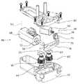
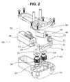
- FIG. 2is an assembled perspective view showing an exemplary actuator.
- FIG. 3is a perspective view showing the actuator of FIG. 2 , when assembly is achieved but there is no cover.
- FIG. 4is a sectional view taken along line IV-IV of FIG. 3 .
- Applicantproposes any combination of any features of claims, partial features of claims and/or any features of the detailed description and individual sentences.
- vehicleor “vehicular” or other similar term as used herein is inclusive of motor vehicles in general such as passenger automobiles including sports utility vehicles (SUV), buses, trucks, various commercial vehicles, watercraft including a variety of boats and ships, aircraft, and the like, and includes hybrid vehicles, electric vehicles, plug-in hybrid electric vehicles, hydrogen-powered vehicles and other alternative fuel vehicles (e.g. fuels derived from resources other than petroleum).
- a hybrid vehicleis a vehicle that has two or more sources of power, for example both gasoline-powered and electric-powered vehicles.
- FIG. 1shows a vehicle seat having a conventional seat carrier 20 , the seat carrier 20 being connected in an articulated manner through a front parallelogram arm 22 and a rear parallelogram arm 24 to a seat rail 26 .
- the seat rail 26extends to move in a longitudinal direction relative to the floor rail 28 .
- the floor rail 28is fixedly formed on a bottom of a vehicle.
- These above-mentioned portions 20 to 28are present, respectively, such that two portions are provided per seat, in other words, one portion is provided on each seat side.
- Two seat carriers 20support one seat area 30 .
- the seat areais connected around the rear shaft 32 to the two seat carriers 20 in an articulated manner.
- an L-shaped lifting armis connected to the seat carrier 20 of at least one seat side in an articulated manner.
- the L-shaped lifting armswivels around an upper shaft of a front parallelogram arm 22 .
- the front parallelogram arm 22is connected to a support portion protruding downwards from the seat carrier 20 in an articulated manner.
- One back restis disposed on the two seat carriers 20 , the back rest being swivelable around a bracket 38 .
- FIG. 1shows a first or upper spindle 44 that may reciprocate in its longitudinal direction.
- the spindle 44is connected to the rear parallelogram arm 24 in an articulated manner, and the articulated connection is performed at a lower position corresponding to approximately 1 ⁇ 4 of an arm length.
- a second or lower spindle adjustable in its axial directionis connected to a downward portion of the lifting arm 34 in an articulated manner.
- a parallelogram defined by the above-mentioned portions 20 to 26is adjusted via the upper spindle 44 associated with the actuator 40 , so that it is possible to adjust a height of the seat.
- a height of a front edge of the seat area 30is adjusted by a lower spindle 46 .
- the frame 42is implemented as a housing composed of two portions. A lower portion of the housing accommodates a drive motor 48 .
- the drive motor 48is swivelably supported in the housing. Such a swivelable support operation is performed around a swivel point, to be more specific, a swivel axis 50 .
- the swivel axisis perpendicular to an axis of an output shaft 52 of the drive motor 48 .
- a swivel range of 1 to 5°, preferably 2 to 3°, and particularly about 2.5°is sufficient. In other words, only a small swivel operation is performed.
- the output shaft 52supports and drives a pinion gear 54 .
- the pinion gear 54is implemented in the form of a screw.
- a motor housingis present between the swivel axis 50 and the pinion gear 54 .
- the swivel axis 50abuts directly on an end of the housing.
- the drive motor 48may rotate between a first position and a second position shown in FIG. 3 .
- the pinion gear 54is coupled to a first toothed wheel 56
- the first toothed wheel 56may rotate in the frame 42 , and may be supported in such a way as to perform only a slight rotation.
- the first toothed wheel 56is formed as a spindle nut.
- the first toothed wheel 56is coupled to the first spindle 44 .
- a second toothed wheel 60is rotatably and may be swivelably supported in the frame in such a way as to be structurally equal to the first toothed wheel 56 .
- the second toothed wheel 60is also implemented as a spindle nut and surrounds the second spindle 46 .
- the two spindles 44 and 46are may be present on one plane that is perpendicular to the swivel axis 50 . However, in the case where the spindles are not only rotatably supported but also is swivelable, each spindle may deviate from the plane by up to 20°.
- a special bearing portion 64is provided in order to enable the swiveling operation.
- the bearing portion 64is present between the individual toothed wheel 56 or 60 and the frame 52 , and its tilting movement is allowed by for example ⁇ 10°, at least ⁇ 2°. Thereby, a slanted position shown in FIG. 4 is achieved.
- the swiveling operation of the drive motor 48 between the first and second positions in the frame 42is performed by an adjusting unit 66 .
- the adjusting unit 66is also disposed in the frame 42 .
- the adjusting unit 66is provided with an electric servo motor 68 .
- the electric servo motor 68is considerably smaller, and occupies 1 ⁇ 4 of a volume of the drive motor 48 , preferably 1 ⁇ 6 thereof.
- the electric servo motor 68is fixedly disposed in the frame 42 , and is not movable relative to the frame 42 .
- the electric servo motordrives a front wheel 70 via the pinion gear using its motor shaft, an eccentric 72 being allotted to the front wheel 70 .
- One shaft protruding forwards from the front wheel 70is supported in the frame 42 .
- a connecting link 74belongs to the adjusting unit 66 , and follows a curvature of a cylinder jacket. In this case, a radius is determined by an interval between the connecting link 74 and the swivel axis 50 .
- the connecting link 74has a bearing indentation 76 , and the eccentric 72 is thus inserted into the bearing indentation 76 .
- the rotating movement around the axisis performed in a longitudinal direction of the connecting link 74 (refer to arrow 78 ).
- a free end of the output shaft 52is rotatably supported in the connecting link 74 .
- the drive motor 48swivels between its two positions. Electric connection portions for the drive motor 48 are formed such that the electric connection portions are operated together by a slight swivel angle.
- the electric connection partsmay extend near the swivel axis 50 .
- the swivel drivemay also engage with the motor housing.
- the connecting link 74has a raised area formed at a center of its length.
- the frameis provided with a housing cover 80 receiving the bearing portion 64 at the other end of the two toothed wheels 56 and 60 .
- the swivel angle around the swivel axis 50is dimensionally set as small as possible. If the pinion gear 54 is disengaged from the first toothed wheel 56 and thus does not engage with the first toothed wheel 56 any more during the replacement of a position, only a small distance of e.g. 1 to 3 mm is present until engagement between the pinion gear 54 and the second toothed wheel 60 is carried out. Therefore, a swiveling distance in an area between the two toothed wheels 56 and 60 is equal to the sum of twice a tooth depth and a small increment x of 0.5 to 5 mm, preferably about 2 to 3 mm.
Landscapes
- Engineering & Computer Science (AREA)
- Mechanical Engineering (AREA)
- Aviation & Aerospace Engineering (AREA)
- Transportation (AREA)
- Power Engineering (AREA)
- General Engineering & Computer Science (AREA)
- Seats For Vehicles (AREA)
- Chairs For Special Purposes, Such As Reclining Chairs (AREA)
Abstract
Description
Claims (10)
Applications Claiming Priority (3)
| Application Number | Priority Date | Filing Date | Title |
|---|---|---|---|
| DE102010063814.5 | 2010-12-21 | ||
| DE102010063814 | 2010-12-21 | ||
| DE102010063814 | 2010-12-21 |
Publications (2)
| Publication Number | Publication Date |
|---|---|
| US20120153755A1 US20120153755A1 (en) | 2012-06-21 |
| US9000641B2true US9000641B2 (en) | 2015-04-07 |
Family
ID=46233452
Family Applications (1)
| Application Number | Title | Priority Date | Filing Date |
|---|---|---|---|
| US13/331,789Active2033-05-14US9000641B2 (en) | 2010-12-21 | 2011-12-20 | Actuator for electric adjusting device of vehicle seat with several adjusting functions |
Country Status (4)
| Country | Link |
|---|---|
| US (1) | US9000641B2 (en) |
| KR (1) | KR101316493B1 (en) |
| CN (1) | CN102653248B (en) |
| DE (1) | DE102011088683B4 (en) |
Cited By (2)
| Publication number | Priority date | Publication date | Assignee | Title |
|---|---|---|---|---|
| US11299071B2 (en) | 2016-12-14 | 2022-04-12 | Brose Fahrzeugteile Gmbh & Co. Kommanditgesellschaft, Coburg | Adjustment device for the longitudinal adjustment of a vehicle seat |
| US20230060468A1 (en)* | 2021-08-30 | 2023-03-02 | Robosen Robotics (Shenzhen) Co., Ltd. | Servo and robot |
Families Citing this family (13)
| Publication number | Priority date | Publication date | Assignee | Title |
|---|---|---|---|---|
| KR20130032757A (en)* | 2011-09-23 | 2013-04-02 | 현대자동차주식회사 | Single motor structure for operation of panorama sunroof glass and roll blind at the same time |
| DE102013212209B3 (en) | 2013-06-26 | 2014-11-27 | Aktiebolaget Skf | actuator |
| WO2017004521A1 (en)* | 2015-07-01 | 2017-01-05 | Magna Seating Inc. | Single motor power seat |
| NL2020641B1 (en)* | 2018-03-21 | 2019-10-02 | Mci Mirror Controls Int Netherlands B V | Drive for an adjusting instrument, in particular for adjusting an outside view unit of a motor vehicle |
| DE102018112019B4 (en)* | 2018-05-18 | 2022-10-06 | Grammer Aktiengesellschaft | Vehicle seat with a damping device |
| DE102019108303B4 (en)* | 2019-03-29 | 2020-12-10 | Mci (Mirror Controls International) Netherlands B.V. | Vision adjustment mechanism and adjusting means for such |
| KR102805145B1 (en)* | 2019-12-10 | 2025-05-08 | 현대자동차주식회사 | Device for tilting seat chusion of fold and dive seat |
| CN113700818B (en)* | 2021-08-09 | 2023-01-17 | 营口机床厂有限公司 | Intermittent forward and backward driving adjusting control mechanism |
| CN113942431B (en)* | 2021-11-28 | 2025-06-27 | 麦格纳汽车技术(上海)有限公司徐汇分公司 | A car seat with integrated height adjustment and angle adjustment |
| CN114899984B (en)* | 2022-05-10 | 2024-10-29 | 永艺家具股份有限公司 | Motion part state change control system for seat |
| KR102778376B1 (en) | 2022-08-12 | 2025-03-10 | 주식회사 아모텍 | Driving Motor Using BLDC Motor and Seat Actuator Using the Same |
| KR102778377B1 (en) | 2022-08-17 | 2025-03-10 | 주식회사 아모텍 | Driving Motor Using BLDC Motor and Seat Actuator Using the Same |
| CN120498186B (en)* | 2025-07-16 | 2025-09-26 | 湖南大学 | Speed regulating device and speed regulating method for deep-sea operation robot |
Citations (4)
| Publication number | Priority date | Publication date | Assignee | Title |
|---|---|---|---|---|
| US20040108146A1 (en)* | 2002-12-09 | 2004-06-10 | Robert Bosch Corporation | Method and system for vehicle occupant weight sensing |
| US7338124B2 (en)* | 2004-02-03 | 2008-03-04 | L&P Property Management Company | Dual drive power actuator |
| US20100048342A1 (en)* | 2005-07-30 | 2010-02-25 | Richard Chadwick | Rotary transmission |
| US7779728B2 (en)* | 2004-08-02 | 2010-08-24 | Flexsys, Inc. | Orienting arrangement for mirror or light source |
Family Cites Families (17)
| Publication number | Priority date | Publication date | Assignee | Title |
|---|---|---|---|---|
| US2930428A (en)* | 1955-08-26 | 1960-03-29 | Rose John P De | Power adjustable seat mount |
| US2886094A (en)* | 1956-04-30 | 1959-05-12 | Ferro Stamping Co | Seat adjusting mechanism |
| US3036806A (en)* | 1958-12-29 | 1962-05-29 | Ferro Stamping Co | Seat adjusting mechanism |
| US3034759A (en)* | 1959-09-03 | 1962-05-15 | Gen Motors Corp | Automatic control for vehicle seat adjusters |
| US3033510A (en)* | 1959-09-08 | 1962-05-08 | Gen Motors Corp | Vehicle seat adjuster |
| US3222025A (en)* | 1964-04-23 | 1965-12-07 | Ferro Mfg Corp | Bucket seat adjuster |
| DE2653680A1 (en)* | 1976-11-26 | 1978-06-01 | Keiper Automobiltechnik Gmbh | MOTOR-ADJUSTABLE SEAT TO BE ARRANGED IN A VEHICLE, PREFERABLY A MOTOR VEHICLE |
| DE8716669U1 (en)* | 1986-12-24 | 1988-03-03 | C. Rob. Hammerstein Gmbh, 5650 Solingen | Vehicle seat with motor-assisted adjustment |
| JPH0530976Y2 (en)* | 1988-03-17 | 1993-08-09 | ||
| US5088841A (en)* | 1988-11-30 | 1992-02-18 | Fuji Kiko Company, Limited | Seat arrangement for automotive vehicle with seat position adjusting system |
| JPH0643400U (en)* | 1992-11-20 | 1994-06-07 | 株式会社タチエス | Geared motor |
| DE20015115U1 (en)* | 2000-09-01 | 2002-01-17 | Johnson Controls GmbH, 51399 Burscheid | Adjustment device for a vehicle seat |
| JP2002159366A (en)* | 2000-11-28 | 2002-06-04 | T S Tec Kk | Vehicle seat |
| DE202004006273U1 (en)* | 2004-04-21 | 2005-09-01 | Brose Fahrzeugteile Gmbh & Co. Kommanditgesellschaft, Coburg | Motor vehicle seat adjusting unit, has spindle pinion with spindle and spindle nut, and motor connected to gear that drives spindle pinion, where motor includes crank and stud, and spindle nut is supported in gear |
| DE102005057462B4 (en)* | 2005-12-01 | 2010-07-29 | Schukra Gerätebau AG | Seat component adjustment device and method as well as seat |
| WO2008058529A2 (en)* | 2006-11-17 | 2008-05-22 | Faurecia Autositze Gmbh | Vehicle seat |
| DE102008023120B4 (en)* | 2008-05-07 | 2010-06-10 | Keiper Gmbh & Co. Kg | Vehicle seat, in particular commercial vehicle seat |
- 2011
- 2011-12-15DEDE102011088683.4Apatent/DE102011088683B4/ennot_activeExpired - Fee Related
- 2011-12-20USUS13/331,789patent/US9000641B2/enactiveActive
- 2011-12-21KRKR1020110138941Apatent/KR101316493B1/ennot_activeExpired - Fee Related
- 2011-12-21CNCN201110433423.9Apatent/CN102653248B/enactiveActive
Patent Citations (4)
| Publication number | Priority date | Publication date | Assignee | Title |
|---|---|---|---|---|
| US20040108146A1 (en)* | 2002-12-09 | 2004-06-10 | Robert Bosch Corporation | Method and system for vehicle occupant weight sensing |
| US7338124B2 (en)* | 2004-02-03 | 2008-03-04 | L&P Property Management Company | Dual drive power actuator |
| US7779728B2 (en)* | 2004-08-02 | 2010-08-24 | Flexsys, Inc. | Orienting arrangement for mirror or light source |
| US20100048342A1 (en)* | 2005-07-30 | 2010-02-25 | Richard Chadwick | Rotary transmission |
Cited By (2)
| Publication number | Priority date | Publication date | Assignee | Title |
|---|---|---|---|---|
| US11299071B2 (en) | 2016-12-14 | 2022-04-12 | Brose Fahrzeugteile Gmbh & Co. Kommanditgesellschaft, Coburg | Adjustment device for the longitudinal adjustment of a vehicle seat |
| US20230060468A1 (en)* | 2021-08-30 | 2023-03-02 | Robosen Robotics (Shenzhen) Co., Ltd. | Servo and robot |
Also Published As
| Publication number | Publication date |
|---|---|
| DE102011088683B4 (en) | 2015-02-12 |
| CN102653248B (en) | 2016-09-21 |
| KR20120070525A (en) | 2012-06-29 |
| DE102011088683A1 (en) | 2012-06-21 |
| CN102653248A (en) | 2012-09-05 |
| US20120153755A1 (en) | 2012-06-21 |
| KR101316493B1 (en) | 2013-10-10 |
Similar Documents
| Publication | Publication Date | Title |
|---|---|---|
| US9000641B2 (en) | Actuator for electric adjusting device of vehicle seat with several adjusting functions | |
| CN111417538B (en) | Adjusting mechanism for adjusting electric multidirectional seat | |
| EP3492311B1 (en) | Clutch-based adjustment mechanism for motorized multi-way seat adjustment | |
| JP5318935B2 (en) | Multi-axis drive | |
| US20150258914A1 (en) | Seat cushion extension apparatus | |
| JPH0732919A (en) | Drive device for vehicle power seat | |
| JP5200609B2 (en) | Power seat slide device | |
| US20100013285A1 (en) | Transmission device for seat adjuster | |
| US20120025582A1 (en) | Seat assembly having an adjustable head restraint assembly | |
| CA2761044C (en) | Single motor power seat | |
| WO2012046868A1 (en) | Power transmission mechanism and multi-shaft drive device | |
| JP6774344B2 (en) | Seat drive | |
| JP2004527275A (en) | Constant engagement linear mechanism | |
| US5924668A (en) | Motorized vehicle seat lift mechanism | |
| US6460819B1 (en) | Automobile seat with inclination adjuster | |
| JP2003056674A (en) | Speed reducer for vehicle seat | |
| EP1571064B1 (en) | Adjustable pedal and steering mechanism | |
| CN110126745B (en) | Adjustable lifting armrest box | |
| JP2011169429A (en) | Driving device for vehicle | |
| JP4320181B2 (en) | Reducer and reclining device | |
| JP2017178096A (en) | Headrest adjustment device | |
| JPH0643399U (en) | Geared motor | |
| JPH1142137A (en) | Power seat drive | |
| JPH0556827A (en) | Power type headless structure | |
| JP2013010432A (en) | Power seat adjuster |
Legal Events
| Date | Code | Title | Description |
|---|---|---|---|
| AS | Assignment | Owner name:HYUNDAI MOTOR COMPANY, KOREA, REPUBLIC OF Free format text:ASSIGNMENT OF ASSIGNORS INTEREST;ASSIGNORS:BURCKHARD, BECKER;SCHWANSE, WERNER;HO, VAN-TOAN;REEL/FRAME:027744/0300 Effective date:20120109 Owner name:C. ROB. HAMMERSTEIN GMBH & CO. KG, GERMANY Free format text:ASSIGNMENT OF ASSIGNORS INTEREST;ASSIGNORS:BURCKHARD, BECKER;SCHWANSE, WERNER;HO, VAN-TOAN;REEL/FRAME:027744/0300 Effective date:20120109 | |
| AS | Assignment | Owner name:HYUNDAI MOTOR COMPANY, KOREA, REPUBLIC OF Free format text:CORRECTIVE ASSIGNMENT TO CORRECT THE TYPOGRAPHICAL/TRANSLITERATION ERROR IN THE FIRST INVENTOR'S NAME TO READ BURCKHARD BECKER, PREVIOUSLY RECORDED ON REEL 027744 FRAME 0300. ASSIGNOR(S) HEREBY CONFIRMS THE ABOVE CORRECTION MADE TO THE FIRST INVENTOR'S NAME;ASSIGNORS:BECKER, BURCKHARD;SCHWANSE, WERNER;HO, VAN-TOAN;REEL/FRAME:027975/0894 Effective date:20120330 Owner name:C. ROB. HAMMERSTEIN GMBH & CO. KG, GERMANY Free format text:CORRECTIVE ASSIGNMENT TO CORRECT THE TYPOGRAPHICAL/TRANSLITERATION ERROR IN THE FIRST INVENTOR'S NAME TO READ BURCKHARD BECKER, PREVIOUSLY RECORDED ON REEL 027744 FRAME 0300. ASSIGNOR(S) HEREBY CONFIRMS THE ABOVE CORRECTION MADE TO THE FIRST INVENTOR'S NAME;ASSIGNORS:BECKER, BURCKHARD;SCHWANSE, WERNER;HO, VAN-TOAN;REEL/FRAME:027975/0894 Effective date:20120330 | |
| FEPP | Fee payment procedure | Free format text:PAYOR NUMBER ASSIGNED (ORIGINAL EVENT CODE: ASPN); ENTITY STATUS OF PATENT OWNER: LARGE ENTITY | |
| STCF | Information on status: patent grant | Free format text:PATENTED CASE | |
| MAFP | Maintenance fee payment | Free format text:PAYMENT OF MAINTENANCE FEE, 4TH YEAR, LARGE ENTITY (ORIGINAL EVENT CODE: M1551); ENTITY STATUS OF PATENT OWNER: LARGE ENTITY Year of fee payment:4 | |
| AS | Assignment | Owner name:JOHNSON CONTROLS METALS AND MECHANISMS GMBH & CO. KG, GERMANY Free format text:CHANGE OF NAME;ASSIGNOR:C. ROB. HAMMERSTEIN GMBH & CO. KG;REEL/FRAME:055026/0770 Effective date:20170421 | |
| AS | Assignment | Owner name:ADIENT LUXEMBOURG HOLDING S.A R.L., LUXEMBOURG Free format text:ASSIGNMENT OF ASSIGNORS INTEREST;ASSIGNOR:JOHNSON CONTROLS METALS AND MECHANISMS GMBH & CO. KG;REEL/FRAME:055170/0344 Effective date:20200724 | |
| AS | Assignment | Owner name:ADIENT GLOBAL HOLDINGS LTD., JERSEY Free format text:ASSIGNMENT OF ASSIGNORS INTEREST;ASSIGNOR:ADIENT LUXEMBOURG HOLDING S.A.R.L.;REEL/FRAME:058671/0541 Effective date:20220110 | |
| AS | Assignment | Owner name:ADIENT US LLC, MICHIGAN Free format text:ASSIGNMENT OF ASSIGNORS INTEREST;ASSIGNOR:ADIENT GLOBAL HOLDINGS LTD.;REEL/FRAME:059002/0568 Effective date:20220127 | |
| MAFP | Maintenance fee payment | Free format text:PAYMENT OF MAINTENANCE FEE, 8TH YEAR, LARGE ENTITY (ORIGINAL EVENT CODE: M1552); ENTITY STATUS OF PATENT OWNER: LARGE ENTITY Year of fee payment:8 | |
| AS | Assignment | Owner name:HYUNDAI MOTOR COMPANY, KOREA, REPUBLIC OF Free format text:ASSIGNMENT OF ASSIGNORS INTEREST;ASSIGNOR:ADIENT US LLC.;REEL/FRAME:062807/0391 Effective date:20230131 |