US9000590B2 - Protruding terminals with internal routing interconnections semiconductor device - Google Patents
Protruding terminals with internal routing interconnections semiconductor deviceDownload PDFInfo
- Publication number
- US9000590B2 US9000590B2US13/851,822US201313851822AUS9000590B2US 9000590 B2US9000590 B2US 9000590B2US 201313851822 AUS201313851822 AUS 201313851822AUS 9000590 B2US9000590 B2US 9000590B2
- Authority
- US
- United States
- Prior art keywords
- semiconductor package
- interconnection
- terminals
- layer
- routings
- Prior art date
- Legal status (The legal status is an assumption and is not a legal conclusion. Google has not performed a legal analysis and makes no representation as to the accuracy of the status listed.)
- Active
Links
- 239000004065semiconductorSubstances0.000titleclaimsabstractdescription87
- 150000001875compoundsChemical class0.000claimsabstractdescription41
- 238000000465mouldingMethods0.000claimsdescription31
- 230000003197catalytic effectEffects0.000claimsdescription7
- 238000013461designMethods0.000claimsdescription5
- 238000004891communicationMethods0.000claimsdescription4
- 230000008878couplingEffects0.000claimsdescription3
- 238000010168coupling processMethods0.000claimsdescription3
- 238000005859coupling reactionMethods0.000claimsdescription3
- 229910000679solderInorganic materials0.000claimsdescription3
- 238000007747platingMethods0.000description31
- 238000000034methodMethods0.000description22
- 239000010949copperSubstances0.000description6
- 229910052802copperInorganic materials0.000description5
- RYGMFSIKBFXOCR-UHFFFAOYSA-NCopperChemical compound[Cu]RYGMFSIKBFXOCR-UHFFFAOYSA-N0.000description4
- 238000004519manufacturing processMethods0.000description4
- 239000004593EpoxySubstances0.000description2
- ORTQZVOHEJQUHG-UHFFFAOYSA-Lcopper(II) chlorideChemical compoundCl[Cu]ClORTQZVOHEJQUHG-UHFFFAOYSA-L0.000description2
- 229920000642polymerPolymers0.000description2
- 229920005989resinPolymers0.000description2
- 239000011347resinSubstances0.000description2
- XLYOFNOQVPJJNP-UHFFFAOYSA-NwaterSubstancesOXLYOFNOQVPJJNP-UHFFFAOYSA-N0.000description2
- 239000000853adhesiveSubstances0.000description1
- 230000001070adhesive effectEffects0.000description1
- 229960003280cupric chlorideDrugs0.000description1
- 230000000694effectsEffects0.000description1
- 238000007772electroless platingMethods0.000description1
- 238000009713electroplatingMethods0.000description1
- 238000005530etchingMethods0.000description1
- PCHJSUWPFVWCPO-UHFFFAOYSA-NgoldChemical compound[Au]PCHJSUWPFVWCPO-UHFFFAOYSA-N0.000description1
- 239000010931goldSubstances0.000description1
- 229910052737goldInorganic materials0.000description1
- 230000000977initiatory effectEffects0.000description1
- 230000001788irregularEffects0.000description1
- 239000000463materialSubstances0.000description1
- 239000007769metal materialSubstances0.000description1
- 238000012545processingMethods0.000description1
- 238000007650screen-printingMethods0.000description1
- 238000007493shaping processMethods0.000description1
- 229910052709silverInorganic materials0.000description1
- 239000007921spraySubstances0.000description1
- 239000000126substanceSubstances0.000description1
- 238000012360testing methodMethods0.000description1
Images


Classifications
- H—ELECTRICITY
- H01—ELECTRIC ELEMENTS
- H01L—SEMICONDUCTOR DEVICES NOT COVERED BY CLASS H10
- H01L23/00—Details of semiconductor or other solid state devices
- H01L23/48—Arrangements for conducting electric current to or from the solid state body in operation, e.g. leads, terminal arrangements ; Selection of materials therefor
- H01L23/488—Arrangements for conducting electric current to or from the solid state body in operation, e.g. leads, terminal arrangements ; Selection of materials therefor consisting of soldered or bonded constructions
- H01L23/498—Leads, i.e. metallisations or lead-frames on insulating substrates, e.g. chip carriers
- H01L23/49811—Additional leads joined to the metallisation on the insulating substrate, e.g. pins, bumps, wires, flat leads
- H01L23/49816—Spherical bumps on the substrate for external connection, e.g. ball grid arrays [BGA]
- H—ELECTRICITY
- H01—ELECTRIC ELEMENTS
- H01L—SEMICONDUCTOR DEVICES NOT COVERED BY CLASS H10
- H01L21/00—Processes or apparatus adapted for the manufacture or treatment of semiconductor or solid state devices or of parts thereof
- H01L21/70—Manufacture or treatment of devices consisting of a plurality of solid state components formed in or on a common substrate or of parts thereof; Manufacture of integrated circuit devices or of parts thereof
- H01L21/77—Manufacture or treatment of devices consisting of a plurality of solid state components or integrated circuits formed in, or on, a common substrate
- H01L21/78—Manufacture or treatment of devices consisting of a plurality of solid state components or integrated circuits formed in, or on, a common substrate with subsequent division of the substrate into plural individual devices
- H—ELECTRICITY
- H01—ELECTRIC ELEMENTS
- H01L—SEMICONDUCTOR DEVICES NOT COVERED BY CLASS H10
- H01L23/00—Details of semiconductor or other solid state devices
- H01L23/48—Arrangements for conducting electric current to or from the solid state body in operation, e.g. leads, terminal arrangements ; Selection of materials therefor
- H01L23/481—Internal lead connections, e.g. via connections, feedthrough structures
- H—ELECTRICITY
- H01—ELECTRIC ELEMENTS
- H01L—SEMICONDUCTOR DEVICES NOT COVERED BY CLASS H10
- H01L24/00—Arrangements for connecting or disconnecting semiconductor or solid-state bodies; Methods or apparatus related thereto
- H01L24/93—Batch processes
- H01L24/95—Batch processes at chip-level, i.e. with connecting carried out on a plurality of singulated devices, i.e. on diced chips
- H01L24/97—Batch processes at chip-level, i.e. with connecting carried out on a plurality of singulated devices, i.e. on diced chips the devices being connected to a common substrate, e.g. interposer, said common substrate being separable into individual assemblies after connecting
- H—ELECTRICITY
- H01—ELECTRIC ELEMENTS
- H01L—SEMICONDUCTOR DEVICES NOT COVERED BY CLASS H10
- H01L2224/00—Indexing scheme for arrangements for connecting or disconnecting semiconductor or solid-state bodies and methods related thereto as covered by H01L24/00
- H01L2224/01—Means for bonding being attached to, or being formed on, the surface to be connected, e.g. chip-to-package, die-attach, "first-level" interconnects; Manufacturing methods related thereto
- H01L2224/10—Bump connectors; Manufacturing methods related thereto
- H01L2224/15—Structure, shape, material or disposition of the bump connectors after the connecting process
- H01L2224/16—Structure, shape, material or disposition of the bump connectors after the connecting process of an individual bump connector
- H—ELECTRICITY
- H01—ELECTRIC ELEMENTS
- H01L—SEMICONDUCTOR DEVICES NOT COVERED BY CLASS H10
- H01L2224/00—Indexing scheme for arrangements for connecting or disconnecting semiconductor or solid-state bodies and methods related thereto as covered by H01L24/00
- H01L2224/01—Means for bonding being attached to, or being formed on, the surface to be connected, e.g. chip-to-package, die-attach, "first-level" interconnects; Manufacturing methods related thereto
- H01L2224/42—Wire connectors; Manufacturing methods related thereto
- H01L2224/44—Structure, shape, material or disposition of the wire connectors prior to the connecting process
- H01L2224/45—Structure, shape, material or disposition of the wire connectors prior to the connecting process of an individual wire connector
- H01L2224/45001—Core members of the connector
- H01L2224/45099—Material
- H01L2224/451—Material with a principal constituent of the material being a metal or a metalloid, e.g. boron (B), silicon (Si), germanium (Ge), arsenic (As), antimony (Sb), tellurium (Te) and polonium (Po), and alloys thereof
- H01L2224/45138—Material with a principal constituent of the material being a metal or a metalloid, e.g. boron (B), silicon (Si), germanium (Ge), arsenic (As), antimony (Sb), tellurium (Te) and polonium (Po), and alloys thereof the principal constituent melting at a temperature of greater than or equal to 950°C and less than 1550°C
- H01L2224/45144—Gold (Au) as principal constituent
- H—ELECTRICITY
- H01—ELECTRIC ELEMENTS
- H01L—SEMICONDUCTOR DEVICES NOT COVERED BY CLASS H10
- H01L2224/00—Indexing scheme for arrangements for connecting or disconnecting semiconductor or solid-state bodies and methods related thereto as covered by H01L24/00
- H01L2224/01—Means for bonding being attached to, or being formed on, the surface to be connected, e.g. chip-to-package, die-attach, "first-level" interconnects; Manufacturing methods related thereto
- H01L2224/42—Wire connectors; Manufacturing methods related thereto
- H01L2224/44—Structure, shape, material or disposition of the wire connectors prior to the connecting process
- H01L2224/45—Structure, shape, material or disposition of the wire connectors prior to the connecting process of an individual wire connector
- H01L2224/45001—Core members of the connector
- H01L2224/45099—Material
- H01L2224/451—Material with a principal constituent of the material being a metal or a metalloid, e.g. boron (B), silicon (Si), germanium (Ge), arsenic (As), antimony (Sb), tellurium (Te) and polonium (Po), and alloys thereof
- H01L2224/45138—Material with a principal constituent of the material being a metal or a metalloid, e.g. boron (B), silicon (Si), germanium (Ge), arsenic (As), antimony (Sb), tellurium (Te) and polonium (Po), and alloys thereof the principal constituent melting at a temperature of greater than or equal to 950°C and less than 1550°C
- H01L2224/45147—Copper (Cu) as principal constituent
- H—ELECTRICITY
- H01—ELECTRIC ELEMENTS
- H01L—SEMICONDUCTOR DEVICES NOT COVERED BY CLASS H10
- H01L2224/00—Indexing scheme for arrangements for connecting or disconnecting semiconductor or solid-state bodies and methods related thereto as covered by H01L24/00
- H01L2224/01—Means for bonding being attached to, or being formed on, the surface to be connected, e.g. chip-to-package, die-attach, "first-level" interconnects; Manufacturing methods related thereto
- H01L2224/42—Wire connectors; Manufacturing methods related thereto
- H01L2224/47—Structure, shape, material or disposition of the wire connectors after the connecting process
- H01L2224/48—Structure, shape, material or disposition of the wire connectors after the connecting process of an individual wire connector
- H01L2224/4805—Shape
- H01L2224/4809—Loop shape
- H01L2224/48091—Arched
- H—ELECTRICITY
- H01—ELECTRIC ELEMENTS
- H01L—SEMICONDUCTOR DEVICES NOT COVERED BY CLASS H10
- H01L2224/00—Indexing scheme for arrangements for connecting or disconnecting semiconductor or solid-state bodies and methods related thereto as covered by H01L24/00
- H01L2224/73—Means for bonding being of different types provided for in two or more of groups H01L2224/10, H01L2224/18, H01L2224/26, H01L2224/34, H01L2224/42, H01L2224/50, H01L2224/63, H01L2224/71
- H01L2224/732—Location after the connecting process
- H01L2224/73251—Location after the connecting process on different surfaces
- H01L2224/73265—Layer and wire connectors
- H—ELECTRICITY
- H01—ELECTRIC ELEMENTS
- H01L—SEMICONDUCTOR DEVICES NOT COVERED BY CLASS H10
- H01L23/00—Details of semiconductor or other solid state devices
- H01L23/28—Encapsulations, e.g. encapsulating layers, coatings, e.g. for protection
- H01L23/31—Encapsulations, e.g. encapsulating layers, coatings, e.g. for protection characterised by the arrangement or shape
- H01L23/3107—Encapsulations, e.g. encapsulating layers, coatings, e.g. for protection characterised by the arrangement or shape the device being completely enclosed
- H01L23/3121—Encapsulations, e.g. encapsulating layers, coatings, e.g. for protection characterised by the arrangement or shape the device being completely enclosed a substrate forming part of the encapsulation
- H01L23/3128—Encapsulations, e.g. encapsulating layers, coatings, e.g. for protection characterised by the arrangement or shape the device being completely enclosed a substrate forming part of the encapsulation the substrate having spherical bumps for external connection
- H—ELECTRICITY
- H01—ELECTRIC ELEMENTS
- H01L—SEMICONDUCTOR DEVICES NOT COVERED BY CLASS H10
- H01L2924/00—Indexing scheme for arrangements or methods for connecting or disconnecting semiconductor or solid-state bodies as covered by H01L24/00
- H—ELECTRICITY
- H01—ELECTRIC ELEMENTS
- H01L—SEMICONDUCTOR DEVICES NOT COVERED BY CLASS H10
- H01L2924/00—Indexing scheme for arrangements or methods for connecting or disconnecting semiconductor or solid-state bodies as covered by H01L24/00
- H01L2924/0001—Technical content checked by a classifier
- H01L2924/00014—Technical content checked by a classifier the subject-matter covered by the group, the symbol of which is combined with the symbol of this group, being disclosed without further technical details
- H—ELECTRICITY
- H01—ELECTRIC ELEMENTS
- H01L—SEMICONDUCTOR DEVICES NOT COVERED BY CLASS H10
- H01L2924/00—Indexing scheme for arrangements or methods for connecting or disconnecting semiconductor or solid-state bodies as covered by H01L24/00
- H01L2924/01—Chemical elements
- H01L2924/01047—Silver [Ag]
- H—ELECTRICITY
- H01—ELECTRIC ELEMENTS
- H01L—SEMICONDUCTOR DEVICES NOT COVERED BY CLASS H10
- H01L2924/00—Indexing scheme for arrangements or methods for connecting or disconnecting semiconductor or solid-state bodies as covered by H01L24/00
- H01L2924/10—Details of semiconductor or other solid state devices to be connected
- H01L2924/11—Device type
- H01L2924/12—Passive devices, e.g. 2 terminal devices
- H01L2924/1204—Optical Diode
- H01L2924/12042—LASER
- H—ELECTRICITY
- H01—ELECTRIC ELEMENTS
- H01L—SEMICONDUCTOR DEVICES NOT COVERED BY CLASS H10
- H01L2924/00—Indexing scheme for arrangements or methods for connecting or disconnecting semiconductor or solid-state bodies as covered by H01L24/00
- H01L2924/15—Details of package parts other than the semiconductor or other solid state devices to be connected
- H01L2924/151—Die mounting substrate
- H01L2924/153—Connection portion
- H01L2924/1531—Connection portion the connection portion being formed only on the surface of the substrate opposite to the die mounting surface
- H01L2924/15311—Connection portion the connection portion being formed only on the surface of the substrate opposite to the die mounting surface being a ball array, e.g. BGA
- H—ELECTRICITY
- H01—ELECTRIC ELEMENTS
- H01L—SEMICONDUCTOR DEVICES NOT COVERED BY CLASS H10
- H01L2924/00—Indexing scheme for arrangements or methods for connecting or disconnecting semiconductor or solid-state bodies as covered by H01L24/00
- H01L2924/15—Details of package parts other than the semiconductor or other solid state devices to be connected
- H01L2924/151—Die mounting substrate
- H01L2924/156—Material
- H01L2924/157—Material with a principal constituent of the material being a metal or a metalloid, e.g. boron [B], silicon [Si], germanium [Ge], arsenic [As], antimony [Sb], tellurium [Te] and polonium [Po], and alloys thereof
- H01L2924/15738—Material with a principal constituent of the material being a metal or a metalloid, e.g. boron [B], silicon [Si], germanium [Ge], arsenic [As], antimony [Sb], tellurium [Te] and polonium [Po], and alloys thereof the principal constituent melting at a temperature of greater than or equal to 950 C and less than 1550 C
- H01L2924/15747—Copper [Cu] as principal constituent
- H—ELECTRICITY
- H01—ELECTRIC ELEMENTS
- H01L—SEMICONDUCTOR DEVICES NOT COVERED BY CLASS H10
- H01L2924/00—Indexing scheme for arrangements or methods for connecting or disconnecting semiconductor or solid-state bodies as covered by H01L24/00
- H01L2924/15—Details of package parts other than the semiconductor or other solid state devices to be connected
- H01L2924/181—Encapsulation
Definitions
- the present inventionis related to the field of semiconductor devices. More specifically, the present invention relates to protruding terminals with routing interconnections semiconductor device.
- Embodiments of the present inventionare directed to protruding terminals with routing interconnections semiconductor device and a method of manufacturing thereof.
- a semiconductor packageincludes terminals extending from a bottom surface of the semiconductor package, and a layer of interconnection routings disposed within the semiconductor package. Each terminal includes a first plated section, a second plated section, and a portion of a sheet carrier from which the semiconductor package is built upon, wherein the portion is coupled between the first and second plated sections.
- Each interconnection routingis electrically coupled with a terminal and can extend planarly therefrom.
- the semiconductor packagealso includes at least one die coupled with the layer of interconnection routings.
- the semiconductor packagealso includes at least one intermediary layers, each including a via layer and an associated routing layer.
- the semiconductor packageincludes a locking mechanism for fastening a package compound with the interconnection routings and the terminals.
- a semiconductor packageincludes interconnection routings forming an interconnection routing layer, a die electrically coupled with the interconnection routing layer, terminals in communication with the interconnection routing layer and protruding from a bottom surface of the semiconductor device, and a package compound.
- Each terminaltypically includes a first plated region, a second plated region, and a metallic strip separating the first plated regions and the second plated region.
- the metallic stripis a section of a sheet carrier, such as a Cu leadframe strip, from which the semiconductor package is built upon.
- the package compoundincludes a top molding compound encapsulating the interconnection routings and the die, and a bottom molding compound surrounding the first plated region of each terminal.
- the package compoundcan include other intermediary molding compounds.
- a width of the second plated region of each terminalis nonuniform.
- the second plated regions and the metallic stripsare nonplanar with the bottom molding compound.
- the interconnection routingsare electrically coupled with the terminals. In some embodiments, at least one of the interconnection routings extends away from a terminal coupled therewith according to a design pattern.
- the semiconductor packagealso includes wire bonds or solder balls that couple the die with the interconnection routing layer.
- the semiconductor packagealso includes at least one other die coupled with the die, the interconnection routing layer, or both.
- the semiconductor packagealso includes at least one intermediary layer.
- Each of the at least one intermediary layerincludes an associated routing layer and a via layer.
- the associated routing layerincludes associated routings electrically coupled with the terminals.
- at least one associated routingextends away from a terminal coupled therewith according to a design pattern.
- the via layerincludes vias electrically coupled with the terminals.
- a semiconductor packagein another aspect, includes terminals coupled at a bottom of the semiconductor package.
- Each of the terminalstypically includes a metallic strip and a plating layer formed on each side of the metallic strip.
- the semiconductor packagealso includes a primary routing layer positioned within the semiconductor package and including primary routings electrically coupled with the terminals. At least one of the primary routings extends planarly therefrom.
- the semiconductor packagealso includes at least one die electrically coupled with the primary routing layer.
- the semiconductor packageincludes a first and second plating layers.
- the first plating layeris coplanar with a molding compound.
- the metallic strip and the second plating layerare nonplanar with the molding compound.
- a distal end of each of the terminalsis tapered.
- a middle portion of each of the terminalsis hourglass-shaped.
- the semiconductor packagealso includes a locking mechanism for fastening a package compound with the primary routings and the terminals.
- the semiconductor packagealso includes at least one intermediary layer coupling with the primary routing layer.
- each of the at least one intermediary layerincludes an associated routing layer having associated routings electrically coupled with the terminals. At least one of the associated routings extends planarly therefrom.
- a pattern formed by the associated routings of the associated routing layeris different from a pattern formed by the primary routings of the primary routing layer.
- the at least one intermediary layeralso includes a via layer having vias. Each via is electrically coupled with a terminal and extend nonplanarly therefrom.
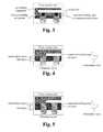
- FIG. 1illustrates an exemplary method of manufacturing a semiconductor package in accordance with the present invention.
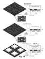
- FIGS. 2A-2Eillustrate an exemplary result produced at each step of the method of FIG. 1 .
- FIG. 3illustrates another exemplary semiconductor package in accordance with the present invention.
- FIG. 4illustrates an exemplary semiconductor package having two routing layers in accordance with the present invention.
- FIG. 5illustrates a cross-sectional view of an exemplary semiconductor package having three routing layers in accordance with the present invention.
- FIG. 6illustrates exemplary semiconductor packages each having a plurality of semiconductor dies in accordance with the present invention.
- Embodiments of the present inventionare directed to plated terminals with routing interconnections semiconductor device.
- a semiconductor packageincludes terminals extending from a bottom surface of the semiconductor package, and a layer of interconnection routings disposed within the semiconductor package. Each terminal includes a first plated section, a second plated section, and a portion of a sheet carrier from which the semiconductor package is built upon, wherein the portion is coupled between the first and second plated sections.
- Each interconnection routingis electrically coupled with a terminal and can extend planarly therefrom.
- the semiconductor packagealso includes at least one die coupled with the layer of interconnection routings. In some embodiments, the semiconductor package also includes at least one intermediary layer, each including a via layer and an associated routing layer.
- the semiconductor packageincludes a locking mechanism for fastening a package compound with the interconnection routings and the terminals.
- FIG. 1illustrates an exemplary method 100 of manufacturing a semiconductor package in accordance with the present invention.
- An exemplary result produced by each step of the method 100is illustrated in FIGS. 2A-2E .
- the method 100begins at a step 105 , where a sheet carrier is provided.
- the sheet carrieris a pure copper leadframe strip.
- the leadframe stripcan be of any other suitable metallic material.
- a plurality of patternsis plated on both sides of the sheet carrier.
- a first portion of patterns plated on a first side of the sheet carrieraligns with a second portion of patterns plated on a second side of the sheet carrier.
- the first sideis typically the top side of the sheet carrier.
- the second sideis typically the bottom side of the sheet carrier.
- the plurality of patternsis plated with Cu, Ag, NiPdAu, or any other suitable material.
- the plurality of patternscan be of any shape and size. As illustrated in FIG. 2A , the patterns are cylindrical and equidistantly separated. The plurality of patterns eventually become part of a plurality of terminals.
- the first side of the sheet carrieris molded with a first molding compound.
- the first molding compoundsurrounds the first portion of patterns on the first side of the sheet carrier.
- the height of the first molding compoundis typically the same as the height of the first portion of patterns.
- the first molding compoundincludes a plastic polymer or resin.
- electrical pathsare formed for a first routing layer.
- the electrical pathsare formed by using catalytic ink to form the electrical paths during a process, such as, a screen printing process or an inkjet writing process.
- the catalytic inkis dropped on the first molding compound according to a product specification.
- the catalytic inkis dropped around the perimeter of each pattern from the first portion of patterns and can be extended planarly therefrom.
- the catalytic inkis formulated ink for initiating copper plating on the first routing layer.
- An exemplary catalytic inkis MicroCat manufactured by MacDermid Incorporated.
- the first routing layeris plated.
- the platingis adhered to a portion of the first molding compound that had been initiated by the catalytic ink. In other words, the plating is adhered to the electrical paths.
- the platingis also adhered to a top surface of each pattern from the first portion of patterns.
- the first routing layercan be plated using an electro plating process or an electroless plating process.
- the electrical pathsare typically conductive and form routings.
- the routings on the first routing layerare interconnection routings.
- the interconnection routingsare electrically coupled with the terminals.
- at least one interconnection routingextends planarly therefrom.
- an interconnection routingis electrically coupled with at least another terminal.
- a first interconnection routingis electrically coupled with a second interconnection routing. This interconnection routing layer is typically configured for coupling with dice.
- diceare placed on the first routing layer.
- the diceare coupled with the first routing layer via epoxy.
- the epoxyis filled in spaces between the interconnection routings, beneath the dice.
- Other adhesivescan be used to couple the dice with the first routing layer.
- Bond wirescouple dice terminals to the interconnection routings.
- the bond wirescan be gold wires, copper wires or any suitable metallic wires.
- the diceare encapsulated with a second molding compound, which also encapsulates the interconnection routings and the bond wires.
- the second molding compoundincludes a plastic polymer or resin.
- the second molding compoundcan be the same as or different from the first molding compound.
- the first molding compound and the second molding compoundbecome part of a package compound.
- unplated portions of the sheet carrierare removed.
- the sheet carrieris removed by applying an etching process, which can be a drip process or a spray process. Once the unplated portions of the sheet carrier are removed, the plurality of terminals protrude from a bottom surface of the sheet carrier. Other processes for removing the unplated portions of the sheet carrier are possible. Typically, the plated areas and the molding are minimally or not affected by the removal of the unplated portions of the sheet carrier.
- the etchant and/or the plating structureare selected such that the etchant is reactive with (removes) the sheet carrier with minimal effect to the plating and the molding.
- a chemical etchantincludes cupric chloride.
- FIG. 2Cwhen unplated areas of the sheet carrier are removed, a middle section of each protruding terminal is hourglass-shaped. However, the middle section of each protruding terminal can be of other shapes per design.
- a plating package terminal peel off problemis minimized.
- the plating package terminal peel off problemis minimized by shaping the protruding terminals.
- a high pressure water jet process or any suitable processcan be used to shape the protruding terminals.
- each terminalhas a tapered tip and a flat end. Other terminal shapes are contemplated.
- a singulation processis performed to separate semiconductor packages from the strip. Singulation can be done using a high-speed saw, a laser, a high-pressure water jet, or some other suitable means. After the step 150 , the method 100 ends. The singulated packages are available for additional testing, processing, shipping and/or use.
- FIG. 2Eshows a top side view and a bottom side view of the singulated semiconductor package.
- the terminalsprotrude from a bottom surface of the semiconductor package and are in electrical communication with the interconnection routing layer.
- a shape of an interconnection routing and a terminal electrically coupled with the interconnection routing and any additional routing layers therebetween(together referred to as simply “terminal”) is irregular and designed for locking with the package compound, which includes at least the first molding compound and the second molding compound.
- each terminalincludes a first plated region and a second plated region formed on opposite sides of a metallic strip.
- the metallic stripis part of the sheet carrier from which the semiconductor package is built upon.
- the first plated regionis surrounded by the first molding compound.
- the first plated regionis coplanar with the first molding compound.
- the second plated region and the metallic stripare nonplanar with the first molding compound.
- a width of the second plated region of each terminalis nonuniform.
- a distal end of each terminalis tapered.
- a middle portion of each terminalis hourglass-shaped.
- the method 100is described relative to bond wire type packages. However, the method 100 is also applicable for flip chip type packages. Instead of using bond wires to couple the dice with the first routing layer at the step 130 , solder balls are used to couple the dice with the first routing layer including the interconnection routings, as illustrated in FIG. 3 .
- a semiconductor dierequires a package that has a more complicated routing circuit than that of the embodiments described above, since a single routing layer is insufficient.
- the concepts of the present inventioncan also be applied for multilayer routing packages by forming at least one intermediary layer that couples with the first routing layer.
- An intermediary layertypically includes a via layer and a subsequent routing layer.
- the method 100can be extended to include, after the plating for the first routing layer step ( 125 ) and before the placing dice on the first routing layer step ( 130 ) of FIG. 1 , a process for creating an intermediary layer.
- the process for creating an intermediary layercan be repeated for each additional intermediary layer.
- a pattern formed by associated routings of a subsequent routing layercan be the same as or different from a pattern formed by interconnection routings of a layer of interconnection routings.
- the pattern formed by the associated routings of the subsequent routing layercan be the same as or different from a pattern formed by interconnection routings of another subsequent routing layer.
- FIG. 4illustrate an exemplary semiconductor package having two routing layers in accordance with the present invention.
- a first plating layerforms a part of protruding terminals of the package.
- a second plating layerincludes an associated routing layer.
- a third plating layerincludes vias that link routing layers, namely the second plating layer and a fourth plating layer.
- the fourth plating layerincludes a bondable layer on which the die is placed for a wire bond type package or a flip chip type package.
- Plating of each layerhas width dimensions different from that of adjacent layers.
- the layerscan have the same or different height dimensions. As discussed above, each layer is formed separately from other layers.
- FIG. 5illustrates a cross-sectional view of an exemplary semiconductor package having three routing layers in accordance with the present invention.
- a first plating layerforms a part of protruding terminals of the package.
- a second plating layerincludes a first associated routing layer.
- a third plating layerincludes vias that link routing layers, namely the second plating layer and a fourth plating layer.
- the fourth plating layerincludes a second associated routing layer.
- a fifth plating layerincludes vias that link routing layers, namely the fourth plating layer and a sixth plating layer.
- the sixth plating layerincludes a bondable layer on which the die is placed for a wire bond type package or a flip chip type package.
- a semiconductor packagein any of the aforementioned semiconductor packages, can also include at least one other die coupled with a die (e.g., stacked dice), at least two dice mounted on the topmost routing layer (e.g., interconnection routing layer), or both within the semiconductor package.
- FIG. 6illustrates exemplary semiconductor packages each having a plurality of semiconductor dies in accordance with the present invention.
Landscapes
- Engineering & Computer Science (AREA)
- Computer Hardware Design (AREA)
- Microelectronics & Electronic Packaging (AREA)
- Power Engineering (AREA)
- Physics & Mathematics (AREA)
- Condensed Matter Physics & Semiconductors (AREA)
- General Physics & Mathematics (AREA)
- Manufacturing & Machinery (AREA)
- Structures Or Materials For Encapsulating Or Coating Semiconductor Devices Or Solid State Devices (AREA)
- Encapsulation Of And Coatings For Semiconductor Or Solid State Devices (AREA)
Abstract
Description
Claims (15)
Priority Applications (1)
| Application Number | Priority Date | Filing Date | Title |
|---|---|---|---|
| US13/851,822US9000590B2 (en) | 2012-05-10 | 2013-03-27 | Protruding terminals with internal routing interconnections semiconductor device |
Applications Claiming Priority (3)
| Application Number | Priority Date | Filing Date | Title |
|---|---|---|---|
| US201261645569P | 2012-05-10 | 2012-05-10 | |
| US201261645560P | 2012-05-10 | 2012-05-10 | |
| US13/851,822US9000590B2 (en) | 2012-05-10 | 2013-03-27 | Protruding terminals with internal routing interconnections semiconductor device |
Publications (2)
| Publication Number | Publication Date |
|---|---|
| US20130299980A1 US20130299980A1 (en) | 2013-11-14 |
| US9000590B2true US9000590B2 (en) | 2015-04-07 |
Family
ID=49548017
Family Applications (2)
| Application Number | Title | Priority Date | Filing Date |
|---|---|---|---|
| US13/850,994Active2033-06-06US9029198B2 (en) | 2012-05-10 | 2013-03-26 | Methods of manufacturing semiconductor devices including terminals with internal routing interconnections |
| US13/851,822ActiveUS9000590B2 (en) | 2012-05-10 | 2013-03-27 | Protruding terminals with internal routing interconnections semiconductor device |
Family Applications Before (1)
| Application Number | Title | Priority Date | Filing Date |
|---|---|---|---|
| US13/850,994Active2033-06-06US9029198B2 (en) | 2012-05-10 | 2013-03-26 | Methods of manufacturing semiconductor devices including terminals with internal routing interconnections |
Country Status (1)
| Country | Link |
|---|---|
| US (2) | US9029198B2 (en) |
Citations (145)
| Publication number | Priority date | Publication date | Assignee | Title |
|---|---|---|---|---|
| US3611061A (en) | 1971-07-07 | 1971-10-05 | Motorola Inc | Multiple lead integrated circuit device and frame member for the fabrication thereof |
| US4411719A (en) | 1980-02-07 | 1983-10-25 | Westinghouse Electric Corp. | Apparatus and method for tape bonding and testing of integrated circuit chips |
| US4501960A (en) | 1981-06-22 | 1985-02-26 | Motorola, Inc. | Micropackage for identification card |
| US4801561A (en) | 1984-07-05 | 1989-01-31 | National Semiconductor Corporation | Method for making a pre-testable semiconductor die package |
| US4855672A (en) | 1987-05-18 | 1989-08-08 | Shreeve Robert W | Method and process for testing the reliability of integrated circuit (IC) chips and novel IC circuitry for accomplishing same |
| US5105259A (en) | 1990-09-28 | 1992-04-14 | Motorola, Inc. | Thermally enhanced semiconductor device utilizing a vacuum to ultimately enhance thermal dissipation |
| US5195023A (en) | 1991-12-23 | 1993-03-16 | At&T Bell Laboratories | Integrated circuit package with strain relief grooves |
| US5247248A (en) | 1991-02-18 | 1993-09-21 | Sharp Kabushiki Kaisha | Burn-in apparatus and method of use thereof |
| US5248075A (en) | 1992-04-13 | 1993-09-28 | Micron Technology, Inc. | IC pin forming machine with integrated IC testing capability |
| US5281851A (en) | 1992-10-02 | 1994-01-25 | Hewlett-Packard Company | Integrated circuit packaging with reinforced leads |
| US5396185A (en) | 1990-08-13 | 1995-03-07 | Kabushiki Kaisha Toshiba | System and carrier for testing semiconductor integrated circuit devices |
| US5397921A (en) | 1993-09-03 | 1995-03-14 | Advanced Semiconductor Assembly Technology | Tab grid array |
| US5479105A (en) | 1993-06-25 | 1995-12-26 | Samsung Electronics Co., Ltd. | Known-good die testing apparatus |
| US5535101A (en) | 1992-11-03 | 1996-07-09 | Motorola, Inc. | Leadless integrated circuit package |
| US5596231A (en) | 1991-08-05 | 1997-01-21 | Asat, Limited | High power dissipation plastic encapsulated package for integrated circuit die |
| US5843808A (en) | 1996-01-11 | 1998-12-01 | Asat, Limited | Structure and method for automated assembly of a tab grid array package |
| US5990692A (en) | 1996-05-10 | 1999-11-23 | Samsung Electronics Co., Ltd. | Testing apparatus for non-packaged semiconductor chip |
| US6072239A (en) | 1995-11-08 | 2000-06-06 | Fujitsu Limited | Device having resin package with projections |
| US6111324A (en) | 1998-02-05 | 2000-08-29 | Asat, Limited | Integrated carrier ring/stiffener and method for manufacturing a flexible integrated circuit package |
| US6159770A (en) | 1995-11-08 | 2000-12-12 | Fujitsu Limited | Method and apparatus for fabricating semiconductor device |
| US6177729B1 (en) | 1999-04-03 | 2001-01-23 | International Business Machines Corporation | Rolling ball connector |
| US6197615B1 (en) | 1997-04-04 | 2001-03-06 | Samsung Electronics Co., Ltd. | Method of producing lead frame having uneven surfaces |
| US6208020B1 (en) | 1999-02-24 | 2001-03-27 | Matsushita Electronics Corporation | Leadframe for use in manufacturing a resin-molded semiconductor device |
| US6229200B1 (en) | 1998-06-10 | 2001-05-08 | Asat Limited | Saw-singulated leadless plastic chip carrier |
| US6250841B1 (en) | 1997-09-22 | 2001-06-26 | Valu Engineering, Inc. | Splice sleeve for guide rails |
| US6285075B1 (en) | 1998-11-02 | 2001-09-04 | Asat, Limited | Integrated circuit package with bonding planes on a ceramic ring using an adhesive assembly |
| US6294100B1 (en) | 1998-06-10 | 2001-09-25 | Asat Ltd | Exposed die leadless plastic chip carrier |
| US6304000B1 (en) | 1997-04-30 | 2001-10-16 | Dow Corning Toray Silicone Company, Ltd. | Semiconductor device comprising silicone adhesive sheet |
| US6326678B1 (en) | 1993-09-03 | 2001-12-04 | Asat, Limited | Molded plastic package with heat sink and enhanced electrical performance |
| US6329711B1 (en) | 1995-11-08 | 2001-12-11 | Fujitsu Limited | Semiconductor device and mounting structure |
| US6353263B1 (en) | 1999-04-14 | 2002-03-05 | Sharp Kabushiki Kaisha | Semiconductor device and manufacturing method thereof |
| US6376921B1 (en) | 1995-11-08 | 2002-04-23 | Fujitsu Limited | Semiconductor device, method for fabricating the semiconductor device, lead frame and method for producing the lead frame |
| US6392427B1 (en) | 1998-12-21 | 2002-05-21 | Kaitech Engineering, Inc. | Testing electronic devices |
| US6414385B1 (en) | 1999-11-08 | 2002-07-02 | Siliconware Precisionindustries Co., Ltd. | Quad flat non-lead package of semiconductor |
| US6429048B1 (en) | 2000-12-05 | 2002-08-06 | Asat Ltd. | Metal foil laminated IC package |
| US20020109214A1 (en) | 2001-02-14 | 2002-08-15 | Masanori Minamio | Leadframe, resin-molded semiconductor device including the leadframe, method of making the leadframe and method for manufacturing the device |
| US6451709B1 (en) | 1998-09-03 | 2002-09-17 | Micron Technology, Inc. | Methodology of removing misplaced encapsulant for attachment of heat sinks in a chip on board package |
| US6455348B1 (en) | 1998-03-12 | 2002-09-24 | Matsushita Electric Industrial Co., Ltd. | Lead frame, resin-molded semiconductor device, and method for manufacturing the same |
| US6489218B1 (en) | 2001-06-21 | 2002-12-03 | Advanced Semiconductor Engineering, Inc. | Singulation method used in leadless packaging process |
| US6498099B1 (en) | 1998-06-10 | 2002-12-24 | Asat Ltd. | Leadless plastic chip carrier with etch back pad singulation |
| US20030006055A1 (en) | 2001-07-05 | 2003-01-09 | Walsin Advanced Electronics Ltd | Semiconductor package for fixed surface mounting |
| US6507116B1 (en) | 1997-04-24 | 2003-01-14 | International Business Machines Corporation | Electronic package and method of forming |
| US20030045032A1 (en) | 2001-08-31 | 2003-03-06 | Shinko Electric Industries Co., Ltd. | Leadframe, method of manufacturing the same, semiconductor device using the same, and method of manufacturing the device |
| US6545332B2 (en) | 2001-01-17 | 2003-04-08 | Siliconware Precision Industries Co., Ltd. | Image sensor of a quad flat package |
| US6545347B2 (en) | 2001-03-06 | 2003-04-08 | Asat, Limited | Enhanced leadless chip carrier |
| US20030071333A1 (en) | 2001-10-15 | 2003-04-17 | Shinko Electric Industries Co., Ltd. | Leadframe, method of manufacturing the same, and method of manufacturing a semiconductor device using the same |
| US6552423B2 (en) | 2000-02-18 | 2003-04-22 | Samsung Electronics Co., Ltd. | Higher-density memory card |
| US6552417B2 (en) | 1993-09-03 | 2003-04-22 | Asat, Limited | Molded plastic package with heat sink and enhanced electrical performance |
| US6566740B2 (en) | 2000-03-23 | 2003-05-20 | Mitsui High-Tec, Inc. | Lead frame for a semiconductor device and method of manufacturing a semiconductor device |
| US6585905B1 (en) | 1998-06-10 | 2003-07-01 | Asat Ltd. | Leadless plastic chip carrier with partial etch die attach pad |
| US6586834B1 (en) | 2002-06-17 | 2003-07-01 | Asat Ltd. | Die-up tape ball grid array package |
| US20030143776A1 (en) | 2002-01-31 | 2003-07-31 | Serafin Pedron | Method of manufacturing an encapsulated integrated circuit package |
| US20030178719A1 (en) | 2002-03-22 | 2003-09-25 | Combs Edward G. | Enhanced thermal dissipation integrated circuit package and method of manufacturing enhanced thermal dissipation integrated circuit package |
| US6635957B2 (en) | 1998-06-10 | 2003-10-21 | Asat Ltd. | Leadless plastic chip carrier with etch back pad singulation and die attach pad array |
| US20030201520A1 (en) | 2002-04-26 | 2003-10-30 | Knapp James H. | Structure and method of forming a multiple leadframe semiconductor device |
| US20030207498A1 (en) | 2002-04-29 | 2003-11-06 | Shafidul Islam | Partially patterned lead frames and methods of making and using the same in semiconductor packaging |
| US6667191B1 (en) | 2002-08-05 | 2003-12-23 | Asat Ltd. | Chip scale integrated circuit package |
| US20040014257A1 (en) | 2002-07-19 | 2004-01-22 | Kim Pyoung Wan | Method for joining lead frames in a package assembly, method for forming a chip stack package, and a chip stack package |
| US6683368B1 (en) | 2000-06-09 | 2004-01-27 | National Semiconductor Corporation | Lead frame design for chip scale package |
| US6686667B2 (en) | 2002-04-22 | 2004-02-03 | Scientek Corp. | Image sensor semiconductor package with castellation |
| US20040026773A1 (en) | 2002-08-08 | 2004-02-12 | Koon Eng Meow | Packaged microelectronic components |
| US6703696B2 (en) | 2000-09-04 | 2004-03-09 | Dainippon Printing Co., Ltd. | Semiconductor package |
| US20040046237A1 (en) | 2002-09-05 | 2004-03-11 | Shinko Electric Industries Co., Ltd | Lead frame and method of manufacturing the same |
| US20040070055A1 (en) | 2002-02-26 | 2004-04-15 | St Assembly Test Services Pte Ltd | Ground plane for exposed package |
| US6723585B1 (en) | 2002-10-31 | 2004-04-20 | National Semiconductor Corporation | Leadless package |
| US20040080025A1 (en) | 2002-09-17 | 2004-04-29 | Shinko Electric Industries Co., Ltd. | Lead frame, method of manufacturing the same, and semiconductor device manufactured with the same |
| US6734044B1 (en) | 2002-06-10 | 2004-05-11 | Asat Ltd. | Multiple leadframe laminated IC package |
| US6734552B2 (en) | 2001-07-11 | 2004-05-11 | Asat Limited | Enhanced thermal dissipation integrated circuit package |
| US6737755B1 (en) | 2002-07-19 | 2004-05-18 | Asat, Ltd. | Ball grid array package with improved thermal characteristics |
| US20040110319A1 (en) | 1994-03-18 | 2004-06-10 | Hitachi Chemical Company, Ltd. | Fabrication process of semiconductor package and semiconductor package |
| US6764880B2 (en) | 2001-11-15 | 2004-07-20 | Siliconware Precision Industries Co., Ltd. | Semiconductor package and fabricating method thereof |
| US6781242B1 (en) | 2002-12-02 | 2004-08-24 | Asat, Ltd. | Thin ball grid array package |
| US6812552B2 (en) | 2002-04-29 | 2004-11-02 | Advanced Interconnect Technologies Limited | Partially patterned lead frames and methods of making and using the same in semiconductor packaging |
| US6818980B1 (en) | 2003-05-07 | 2004-11-16 | Asat Ltd. | Stacked semiconductor package and method of manufacturing the same |
| US6818978B1 (en) | 2002-11-19 | 2004-11-16 | Asat Ltd. | Ball grid array package with shielding |
| US20050003586A1 (en) | 2001-05-11 | 2005-01-06 | Renesas Technology Corporation | Manufacturing method of a semiconductor device |
| US6841859B1 (en) | 2002-09-03 | 2005-01-11 | Asat Ltd. | Premolded cavity IC package |
| US6876066B2 (en) | 2001-08-29 | 2005-04-05 | Micron Technology, Inc. | Packaged microelectronic devices and methods of forming same |
| US20050077613A1 (en) | 2002-01-31 | 2005-04-14 | Mclellan Neil Robert | Integrated circuit package |
| US6894376B1 (en) | 2003-06-09 | 2005-05-17 | National Semiconductor Corporation | Leadless microelectronic package and a method to maximize the die size in the package |
| US6893169B1 (en) | 1999-11-04 | 2005-05-17 | Stmicroelectronics S.A. | Optical semiconductor package and process for fabricating the same |
| US6897428B2 (en) | 2003-07-01 | 2005-05-24 | Matsushita Electric Industrial Co., Ltd. | Solid-state imaging device and method for manufacturing the same |
| US6927483B1 (en) | 2003-03-07 | 2005-08-09 | Amkor Technology, Inc. | Semiconductor package exhibiting efficient lead placement |
| US6933176B1 (en) | 2002-07-19 | 2005-08-23 | Asat Ltd. | Ball grid array package and process for manufacturing same |
| US6933594B2 (en) | 1998-06-10 | 2005-08-23 | Asat Ltd. | Leadless plastic chip carrier with etch back pad singulation |
| US6940154B2 (en) | 2002-06-24 | 2005-09-06 | Asat Limited | Integrated circuit package and method of manufacturing the integrated circuit package |
| US6946324B1 (en) | 1998-06-10 | 2005-09-20 | Asat Ltd. | Process for fabricating a leadless plastic chip carrier |
| US20050236701A1 (en) | 2002-10-24 | 2005-10-27 | Matsushita Electric Industrial Co., Ltd. | Leadframe, plastic-encapsulated semiconductor device, and method for fabricating the same |
| US6967126B2 (en) | 2001-07-31 | 2005-11-22 | Chippac, Inc. | Method for manufacturing plastic ball grid array with integral heatsink |
| US6979594B1 (en) | 2002-07-19 | 2005-12-27 | Asat Ltd. | Process for manufacturing ball grid array package |
| US6982491B1 (en) | 2004-01-20 | 2006-01-03 | Asat Ltd. | Sensor semiconductor package and method of manufacturing the same |
| US6984785B1 (en) | 2003-10-27 | 2006-01-10 | Asat Ltd. | Thermally enhanced cavity-down integrated circuit package |
| US7009286B1 (en) | 2004-01-15 | 2006-03-07 | Asat Ltd. | Thin leadless plastic chip carrier |
| US7008825B1 (en) | 2003-05-27 | 2006-03-07 | Amkor Technology, Inc. | Leadframe strip having enhanced testability |
| US20060071351A1 (en) | 2004-09-28 | 2006-04-06 | Texas Instruments Incorporated | Mold compound interlocking feature to improve semiconductor package strength |
| US7045883B1 (en) | 2001-04-04 | 2006-05-16 | Amkor Technology, Inc. | Thermally enhanced chip scale lead on chip semiconductor package and method of making same |
| US7049177B1 (en) | 2004-01-28 | 2006-05-23 | Asat Ltd. | Leadless plastic chip carrier with standoff contacts and die attach pad |
| US7052935B2 (en) | 2003-02-26 | 2006-05-30 | Advanced Semiconductor Engineering, Inc. | Flip-chip package and fabricating process thereof |
| US7060535B1 (en) | 2003-10-29 | 2006-06-13 | Ns Electronics Bangkok (1993) Ltd. | Flat no-lead semiconductor die package including stud terminals |
| US7071545B1 (en) | 2002-12-20 | 2006-07-04 | Asat Ltd. | Shielded integrated circuit package |
| US20060170081A1 (en) | 2005-02-03 | 2006-08-03 | Gerber Mark A | Method and apparatus for packaging an electronic chip |
| US7091581B1 (en) | 2004-06-14 | 2006-08-15 | Asat Limited | Integrated circuit package and process for fabricating the same |
| US20060192295A1 (en) | 2004-11-17 | 2006-08-31 | Chippac, Inc. | Semiconductor package flip chip interconnect having spacer |
| US7102210B2 (en) | 2003-09-05 | 2006-09-05 | Oki Electric Industry Co., Ltd. | Lead frame, manufacturing method of the same, and semiconductor device using the same |
| US7101210B2 (en) | 2004-11-26 | 2006-09-05 | Hon Hai Precision Ind. Co., Ltd. | LGA socket |
| US20060223237A1 (en) | 2001-07-11 | 2006-10-05 | Combs Edward G | Method of manufacturing enhanced thermal dissipation integrated circuit package |
| US7125747B2 (en) | 2004-06-23 | 2006-10-24 | Advanced Semiconductor Engineering, Inc. | Process for manufacturing leadless semiconductor packages including an electrical test in a matrix of a leadless leadframe |
| US20060273433A1 (en) | 2002-04-01 | 2006-12-07 | Matsushita Electric Industrial Co., Ltd. | Semiconductor device |
| US20070001278A1 (en) | 2005-06-30 | 2007-01-04 | Oseob Jeon | Semiconductor die package and method for making the same |
| US20070013038A1 (en) | 2005-07-13 | 2007-01-18 | Advanced Semiconductor Engineering, Inc. | Semiconductor package having pre-plated leads and method of manufacturing the same |
| US20070029540A1 (en) | 1999-01-28 | 2007-02-08 | Ryoichi Kajiwara | Semiconductor device |
| US7205178B2 (en) | 2004-03-24 | 2007-04-17 | Freescale Semiconductor, Inc. | Land grid array packaged device and method of forming same |
| US7247526B1 (en) | 1998-06-10 | 2007-07-24 | Asat Ltd. | Process for fabricating an integrated circuit package |
| US7253503B1 (en) | 1999-11-05 | 2007-08-07 | Amkor Technology, Inc. | Integrated circuit device packages and substrates for making the packages |
| US7259678B2 (en) | 2003-12-08 | 2007-08-21 | 3M Innovative Properties Company | Durable radio frequency identification label and methods of manufacturing the same |
| US20070200210A1 (en) | 2006-02-28 | 2007-08-30 | Broadcom Corporation | Methods and apparatus for improved thermal performance and electromagnetic interference (EMI) shielding in integrated circuit (IC) packages |
| US7274088B2 (en) | 2002-06-14 | 2007-09-25 | Siliconware Precision Industries Co., Ltd. | Flip-chip semiconductor package with lead frame as chip carrier and fabrication method thereof |
| US20070235217A1 (en) | 2006-03-29 | 2007-10-11 | Workman Derek B | Devices with microjetted polymer standoffs |
| US7314820B2 (en) | 2004-12-02 | 2008-01-01 | Siliconware Precision Industries Co., Ltd. | Carrier-free semiconductor package and fabrication method thereof |
| US7315077B2 (en) | 2003-11-13 | 2008-01-01 | Fairchild Korea Semiconductor, Ltd. | Molded leadless package having a partially exposed lead frame pad |
| US20080048308A1 (en) | 2006-08-28 | 2008-02-28 | Atmel Corporation | Stackable packages for three-dimensional packaging of semiconductor dice |
| US7344920B1 (en) | 2005-07-15 | 2008-03-18 | Asat Ltd. | Integrated circuit package and method for fabricating same |
| US7358119B2 (en) | 2005-01-12 | 2008-04-15 | Asat Ltd. | Thin array plastic package without die attach pad and process for fabricating the same |
| US7372151B1 (en) | 2003-09-12 | 2008-05-13 | Asat Ltd. | Ball grid array package and process for manufacturing same |
| US20080150094A1 (en) | 2006-12-21 | 2008-06-26 | M/A-Com, Inc. | Flip chip shielded RF I/O land grid array package |
| US7399658B2 (en) | 2005-10-21 | 2008-07-15 | Stats Chippac Ltd. | Pre-molded leadframe and method therefor |
| US7408251B2 (en) | 2003-07-31 | 2008-08-05 | Renesas Technology Corp. | Semiconductor packaging device comprising a semiconductor chip including a MOSFET |
| US7411289B1 (en) | 2004-06-14 | 2008-08-12 | Asat Ltd. | Integrated circuit package with partially exposed contact pads and process for fabricating the same |
| US7459345B2 (en) | 2004-10-20 | 2008-12-02 | Mutual-Pak Technology Co., Ltd. | Packaging method for an electronic element |
| US7495319B2 (en) | 2004-03-04 | 2009-02-24 | Panasonic Corporation | Resin-encapsulated semiconductor device and lead frame, and method for manufacturing the same |
| US7507603B1 (en) | 2005-12-02 | 2009-03-24 | Amkor Technology, Inc. | Etch singulated semiconductor package |
| US20090152691A1 (en) | 2007-12-18 | 2009-06-18 | National Semiconductor Corporation | Leadframe having die attach pad with delamination and crack-arresting features |
| US20090152694A1 (en) | 2007-12-12 | 2009-06-18 | Infineon Technologies Ag | Electronic device |
| US20090230525A1 (en) | 2008-03-14 | 2009-09-17 | Pao-Huei Chang Chien | Advanced quad flat no lead chip package having marking and corner lead features and manufacturing methods thereof |
| US20090236713A1 (en) | 2008-03-19 | 2009-09-24 | Freescale Semiconductor, Inc. | Semiconductor integrated circuit package and method of packaging semiconductor integrated circuit |
| US7595225B1 (en) | 2004-10-05 | 2009-09-29 | Chun Ho Fan | Leadless plastic chip carrier with contact standoff |
| US7608484B2 (en) | 2006-10-31 | 2009-10-27 | Texas Instruments Incorporated | Non-pull back pad package with an additional solder standoff |
| US7709857B2 (en) | 2007-04-24 | 2010-05-04 | Samsung Electro-Mechanics Co., Ltd. | Light emitting diode package |
| US7714418B2 (en) | 2007-07-23 | 2010-05-11 | National Semiconductor Corporation | Leadframe panel |
| US20100133565A1 (en) | 2008-12-03 | 2010-06-03 | Seoul Semiconductor Co., Ltd. | Lead frame, light emitting diode having the lead frame, and backlight unit having the light emitting diode |
| US20100149773A1 (en) | 2008-12-17 | 2010-06-17 | Mohd Hanafi Mohd Said | Integrated circuit packages having shared die-to-die contacts and methods to manufacture the same |
| US20110201159A1 (en) | 2008-11-05 | 2011-08-18 | Mitsui High-Tec, Inc. | Semiconductor package and manufacturing method thereof |
| US20110198752A1 (en)* | 2006-04-28 | 2011-08-18 | Utac Thai Limited | Lead frame ball grid array with traces under die |
| US8035207B2 (en) | 2006-12-30 | 2011-10-11 | Stats Chippac Ltd. | Stackable integrated circuit package system with recess |
| US8089159B1 (en)* | 2007-10-03 | 2012-01-03 | Amkor Technology, Inc. | Semiconductor package with increased I/O density and method of making the same |
Family Cites Families (2)
| Publication number | Priority date | Publication date | Assignee | Title |
|---|---|---|---|---|
| US7943434B2 (en)* | 2008-03-21 | 2011-05-17 | Occam Portfolio Llc | Monolithic molded flexible electronic assemblies without solder and methods for their manufacture |
| US9230933B2 (en) | 2011-09-16 | 2016-01-05 | STATS ChipPAC, Ltd | Semiconductor device and method of forming conductive protrusion over conductive pillars or bond pads as fixed offset vertical interconnect structure |
- 2013
- 2013-03-26USUS13/850,994patent/US9029198B2/enactiveActive
- 2013-03-27USUS13/851,822patent/US9000590B2/enactiveActive
Patent Citations (165)
| Publication number | Priority date | Publication date | Assignee | Title |
|---|---|---|---|---|
| US3611061A (en) | 1971-07-07 | 1971-10-05 | Motorola Inc | Multiple lead integrated circuit device and frame member for the fabrication thereof |
| US4411719A (en) | 1980-02-07 | 1983-10-25 | Westinghouse Electric Corp. | Apparatus and method for tape bonding and testing of integrated circuit chips |
| US4501960A (en) | 1981-06-22 | 1985-02-26 | Motorola, Inc. | Micropackage for identification card |
| US4801561A (en) | 1984-07-05 | 1989-01-31 | National Semiconductor Corporation | Method for making a pre-testable semiconductor die package |
| US4855672A (en) | 1987-05-18 | 1989-08-08 | Shreeve Robert W | Method and process for testing the reliability of integrated circuit (IC) chips and novel IC circuitry for accomplishing same |
| US5396185A (en) | 1990-08-13 | 1995-03-07 | Kabushiki Kaisha Toshiba | System and carrier for testing semiconductor integrated circuit devices |
| US5105259A (en) | 1990-09-28 | 1992-04-14 | Motorola, Inc. | Thermally enhanced semiconductor device utilizing a vacuum to ultimately enhance thermal dissipation |
| US5247248A (en) | 1991-02-18 | 1993-09-21 | Sharp Kabushiki Kaisha | Burn-in apparatus and method of use thereof |
| US5596231A (en) | 1991-08-05 | 1997-01-21 | Asat, Limited | High power dissipation plastic encapsulated package for integrated circuit die |
| US5195023A (en) | 1991-12-23 | 1993-03-16 | At&T Bell Laboratories | Integrated circuit package with strain relief grooves |
| US5248075A (en) | 1992-04-13 | 1993-09-28 | Micron Technology, Inc. | IC pin forming machine with integrated IC testing capability |
| US5281851A (en) | 1992-10-02 | 1994-01-25 | Hewlett-Packard Company | Integrated circuit packaging with reinforced leads |
| US5535101A (en) | 1992-11-03 | 1996-07-09 | Motorola, Inc. | Leadless integrated circuit package |
| US5479105A (en) | 1993-06-25 | 1995-12-26 | Samsung Electronics Co., Ltd. | Known-good die testing apparatus |
| US6326678B1 (en) | 1993-09-03 | 2001-12-04 | Asat, Limited | Molded plastic package with heat sink and enhanced electrical performance |
| US6724071B2 (en) | 1993-09-03 | 2004-04-20 | Asat, Limited | Molded plastic package with heat sink and enhanced electrical performance |
| US6552417B2 (en) | 1993-09-03 | 2003-04-22 | Asat, Limited | Molded plastic package with heat sink and enhanced electrical performance |
| US5397921A (en) | 1993-09-03 | 1995-03-14 | Advanced Semiconductor Assembly Technology | Tab grid array |
| US20040110319A1 (en) | 1994-03-18 | 2004-06-10 | Hitachi Chemical Company, Ltd. | Fabrication process of semiconductor package and semiconductor package |
| US6072239A (en) | 1995-11-08 | 2000-06-06 | Fujitsu Limited | Device having resin package with projections |
| US6573121B2 (en) | 1995-11-08 | 2003-06-03 | Fujitsu Limited | Semiconductor device, method for fabricating the semiconductor device, lead frame and method for producing the lead frame |
| US6159770A (en) | 1995-11-08 | 2000-12-12 | Fujitsu Limited | Method and apparatus for fabricating semiconductor device |
| US6376921B1 (en) | 1995-11-08 | 2002-04-23 | Fujitsu Limited | Semiconductor device, method for fabricating the semiconductor device, lead frame and method for producing the lead frame |
| US6329711B1 (en) | 1995-11-08 | 2001-12-11 | Fujitsu Limited | Semiconductor device and mounting structure |
| US5843808A (en) | 1996-01-11 | 1998-12-01 | Asat, Limited | Structure and method for automated assembly of a tab grid array package |
| US5990692A (en) | 1996-05-10 | 1999-11-23 | Samsung Electronics Co., Ltd. | Testing apparatus for non-packaged semiconductor chip |
| US6197615B1 (en) | 1997-04-04 | 2001-03-06 | Samsung Electronics Co., Ltd. | Method of producing lead frame having uneven surfaces |
| US6507116B1 (en) | 1997-04-24 | 2003-01-14 | International Business Machines Corporation | Electronic package and method of forming |
| US6304000B1 (en) | 1997-04-30 | 2001-10-16 | Dow Corning Toray Silicone Company, Ltd. | Semiconductor device comprising silicone adhesive sheet |
| US6250841B1 (en) | 1997-09-22 | 2001-06-26 | Valu Engineering, Inc. | Splice sleeve for guide rails |
| US6284569B1 (en) | 1998-02-05 | 2001-09-04 | Asat, Limited | Method of manufacturing a flexible integrated circuit package utilizing an integrated carrier ring/stiffener |
| US6111324A (en) | 1998-02-05 | 2000-08-29 | Asat, Limited | Integrated carrier ring/stiffener and method for manufacturing a flexible integrated circuit package |
| US6455348B1 (en) | 1998-03-12 | 2002-09-24 | Matsushita Electric Industrial Co., Ltd. | Lead frame, resin-molded semiconductor device, and method for manufacturing the same |
| US6585905B1 (en) | 1998-06-10 | 2003-07-01 | Asat Ltd. | Leadless plastic chip carrier with partial etch die attach pad |
| US6989294B1 (en) | 1998-06-10 | 2006-01-24 | Asat, Ltd. | Leadless plastic chip carrier with etch back pad singulation |
| US7482690B1 (en) | 1998-06-10 | 2009-01-27 | Asat Ltd. | Electronic components such as thin array plastic packages and process for fabricating same |
| US7247526B1 (en) | 1998-06-10 | 2007-07-24 | Asat Ltd. | Process for fabricating an integrated circuit package |
| US6946324B1 (en) | 1998-06-10 | 2005-09-20 | Asat Ltd. | Process for fabricating a leadless plastic chip carrier |
| US6635957B2 (en) | 1998-06-10 | 2003-10-21 | Asat Ltd. | Leadless plastic chip carrier with etch back pad singulation and die attach pad array |
| US6294100B1 (en) | 1998-06-10 | 2001-09-25 | Asat Ltd | Exposed die leadless plastic chip carrier |
| US6964918B1 (en) | 1998-06-10 | 2005-11-15 | Asat Ltd. | Electronic components such as thin array plastic packages and process for fabricating same |
| US6498099B1 (en) | 1998-06-10 | 2002-12-24 | Asat Ltd. | Leadless plastic chip carrier with etch back pad singulation |
| US6242281B1 (en) | 1998-06-10 | 2001-06-05 | Asat, Limited | Saw-singulated leadless plastic chip carrier |
| US6995460B1 (en) | 1998-06-10 | 2006-02-07 | Asat Ltd. | Leadless plastic chip carrier with etch back pad singulation |
| US6229200B1 (en) | 1998-06-10 | 2001-05-08 | Asat Limited | Saw-singulated leadless plastic chip carrier |
| US6933594B2 (en) | 1998-06-10 | 2005-08-23 | Asat Ltd. | Leadless plastic chip carrier with etch back pad singulation |
| US6451709B1 (en) | 1998-09-03 | 2002-09-17 | Micron Technology, Inc. | Methodology of removing misplaced encapsulant for attachment of heat sinks in a chip on board package |
| US6285075B1 (en) | 1998-11-02 | 2001-09-04 | Asat, Limited | Integrated circuit package with bonding planes on a ceramic ring using an adhesive assembly |
| US6392427B1 (en) | 1998-12-21 | 2002-05-21 | Kaitech Engineering, Inc. | Testing electronic devices |
| US20070029540A1 (en) | 1999-01-28 | 2007-02-08 | Ryoichi Kajiwara | Semiconductor device |
| US6208020B1 (en) | 1999-02-24 | 2001-03-27 | Matsushita Electronics Corporation | Leadframe for use in manufacturing a resin-molded semiconductor device |
| US6177729B1 (en) | 1999-04-03 | 2001-01-23 | International Business Machines Corporation | Rolling ball connector |
| US6353263B1 (en) | 1999-04-14 | 2002-03-05 | Sharp Kabushiki Kaisha | Semiconductor device and manufacturing method thereof |
| US6893169B1 (en) | 1999-11-04 | 2005-05-17 | Stmicroelectronics S.A. | Optical semiconductor package and process for fabricating the same |
| US7253503B1 (en) | 1999-11-05 | 2007-08-07 | Amkor Technology, Inc. | Integrated circuit device packages and substrates for making the packages |
| US6414385B1 (en) | 1999-11-08 | 2002-07-02 | Siliconware Precisionindustries Co., Ltd. | Quad flat non-lead package of semiconductor |
| US6552423B2 (en) | 2000-02-18 | 2003-04-22 | Samsung Electronics Co., Ltd. | Higher-density memory card |
| US6566740B2 (en) | 2000-03-23 | 2003-05-20 | Mitsui High-Tec, Inc. | Lead frame for a semiconductor device and method of manufacturing a semiconductor device |
| US6683368B1 (en) | 2000-06-09 | 2004-01-27 | National Semiconductor Corporation | Lead frame design for chip scale package |
| US6703696B2 (en) | 2000-09-04 | 2004-03-09 | Dainippon Printing Co., Ltd. | Semiconductor package |
| US6429048B1 (en) | 2000-12-05 | 2002-08-06 | Asat Ltd. | Metal foil laminated IC package |
| US6545332B2 (en) | 2001-01-17 | 2003-04-08 | Siliconware Precision Industries Co., Ltd. | Image sensor of a quad flat package |
| US20020109214A1 (en) | 2001-02-14 | 2002-08-15 | Masanori Minamio | Leadframe, resin-molded semiconductor device including the leadframe, method of making the leadframe and method for manufacturing the device |
| US6545347B2 (en) | 2001-03-06 | 2003-04-08 | Asat, Limited | Enhanced leadless chip carrier |
| US7045883B1 (en) | 2001-04-04 | 2006-05-16 | Amkor Technology, Inc. | Thermally enhanced chip scale lead on chip semiconductor package and method of making same |
| US20050003586A1 (en) | 2001-05-11 | 2005-01-06 | Renesas Technology Corporation | Manufacturing method of a semiconductor device |
| US6489218B1 (en) | 2001-06-21 | 2002-12-03 | Advanced Semiconductor Engineering, Inc. | Singulation method used in leadless packaging process |
| US20030006055A1 (en) | 2001-07-05 | 2003-01-09 | Walsin Advanced Electronics Ltd | Semiconductor package for fixed surface mounting |
| US20060223237A1 (en) | 2001-07-11 | 2006-10-05 | Combs Edward G | Method of manufacturing enhanced thermal dissipation integrated circuit package |
| US6734552B2 (en) | 2001-07-11 | 2004-05-11 | Asat Limited | Enhanced thermal dissipation integrated circuit package |
| US6967126B2 (en) | 2001-07-31 | 2005-11-22 | Chippac, Inc. | Method for manufacturing plastic ball grid array with integral heatsink |
| US6876066B2 (en) | 2001-08-29 | 2005-04-05 | Micron Technology, Inc. | Packaged microelectronic devices and methods of forming same |
| US20030045032A1 (en) | 2001-08-31 | 2003-03-06 | Shinko Electric Industries Co., Ltd. | Leadframe, method of manufacturing the same, semiconductor device using the same, and method of manufacturing the device |
| US20030071333A1 (en) | 2001-10-15 | 2003-04-17 | Shinko Electric Industries Co., Ltd. | Leadframe, method of manufacturing the same, and method of manufacturing a semiconductor device using the same |
| US6764880B2 (en) | 2001-11-15 | 2004-07-20 | Siliconware Precision Industries Co., Ltd. | Semiconductor package and fabricating method thereof |
| US20030143776A1 (en) | 2002-01-31 | 2003-07-31 | Serafin Pedron | Method of manufacturing an encapsulated integrated circuit package |
| US20050077613A1 (en) | 2002-01-31 | 2005-04-14 | Mclellan Neil Robert | Integrated circuit package |
| US20040070055A1 (en) | 2002-02-26 | 2004-04-15 | St Assembly Test Services Pte Ltd | Ground plane for exposed package |
| US20030178719A1 (en) | 2002-03-22 | 2003-09-25 | Combs Edward G. | Enhanced thermal dissipation integrated circuit package and method of manufacturing enhanced thermal dissipation integrated circuit package |
| US20040046241A1 (en) | 2002-03-22 | 2004-03-11 | Combs Edward G. | Method of manufacturing enhanced thermal dissipation integrated circuit package |
| US20060273433A1 (en) | 2002-04-01 | 2006-12-07 | Matsushita Electric Industrial Co., Ltd. | Semiconductor device |
| US6686667B2 (en) | 2002-04-22 | 2004-02-03 | Scientek Corp. | Image sensor semiconductor package with castellation |
| US20030201520A1 (en) | 2002-04-26 | 2003-10-30 | Knapp James H. | Structure and method of forming a multiple leadframe semiconductor device |
| US6812552B2 (en) | 2002-04-29 | 2004-11-02 | Advanced Interconnect Technologies Limited | Partially patterned lead frames and methods of making and using the same in semiconductor packaging |
| US20050263864A1 (en) | 2002-04-29 | 2005-12-01 | Shafidul Islam | Partially patterned lead frames and methods of making and using the same in semiconductor packaging |
| US20030207498A1 (en) | 2002-04-29 | 2003-11-06 | Shafidul Islam | Partially patterned lead frames and methods of making and using the same in semiconductor packaging |
| US6734044B1 (en) | 2002-06-10 | 2004-05-11 | Asat Ltd. | Multiple leadframe laminated IC package |
| US7449771B1 (en) | 2002-06-10 | 2008-11-11 | Asat Ltd. | Multiple leadframe laminated IC package |
| US7274088B2 (en) | 2002-06-14 | 2007-09-25 | Siliconware Precision Industries Co., Ltd. | Flip-chip semiconductor package with lead frame as chip carrier and fabrication method thereof |
| US6586834B1 (en) | 2002-06-17 | 2003-07-01 | Asat Ltd. | Die-up tape ball grid array package |
| US6940154B2 (en) | 2002-06-24 | 2005-09-06 | Asat Limited | Integrated circuit package and method of manufacturing the integrated circuit package |
| US6818472B1 (en) | 2002-07-19 | 2004-11-16 | Asat Ltd. | Ball grid array package |
| US20040014257A1 (en) | 2002-07-19 | 2004-01-22 | Kim Pyoung Wan | Method for joining lead frames in a package assembly, method for forming a chip stack package, and a chip stack package |
| US7315080B1 (en) | 2002-07-19 | 2008-01-01 | Asat Ltd. | Ball grid array package that includes a collapsible spacer for separating die adapter from a heat spreader |
| US20060223229A1 (en) | 2002-07-19 | 2006-10-05 | Asat Ltd. | Ball grid array package and process for manufacturing same |
| US6800948B1 (en) | 2002-07-19 | 2004-10-05 | Asat Ltd. | Ball grid array package |
| US7371610B1 (en) | 2002-07-19 | 2008-05-13 | Asat Ltd. | Process for fabricating an integrated circuit package with reduced mold warping |
| US6979594B1 (en) | 2002-07-19 | 2005-12-27 | Asat Ltd. | Process for manufacturing ball grid array package |
| US6933176B1 (en) | 2002-07-19 | 2005-08-23 | Asat Ltd. | Ball grid array package and process for manufacturing same |
| US6737755B1 (en) | 2002-07-19 | 2004-05-18 | Asat, Ltd. | Ball grid array package with improved thermal characteristics |
| US7224048B1 (en) | 2002-08-05 | 2007-05-29 | Asat Ltd. | Flip chip ball grid array package |
| US6667191B1 (en) | 2002-08-05 | 2003-12-23 | Asat Ltd. | Chip scale integrated circuit package |
| US20040026773A1 (en) | 2002-08-08 | 2004-02-12 | Koon Eng Meow | Packaged microelectronic components |
| US6841859B1 (en) | 2002-09-03 | 2005-01-11 | Asat Ltd. | Premolded cavity IC package |
| US20040046237A1 (en) | 2002-09-05 | 2004-03-11 | Shinko Electric Industries Co., Ltd | Lead frame and method of manufacturing the same |
| US20040080025A1 (en) | 2002-09-17 | 2004-04-29 | Shinko Electric Industries Co., Ltd. | Lead frame, method of manufacturing the same, and semiconductor device manufactured with the same |
| US20050236701A1 (en) | 2002-10-24 | 2005-10-27 | Matsushita Electric Industrial Co., Ltd. | Leadframe, plastic-encapsulated semiconductor device, and method for fabricating the same |
| US6723585B1 (en) | 2002-10-31 | 2004-04-20 | National Semiconductor Corporation | Leadless package |
| US6818978B1 (en) | 2002-11-19 | 2004-11-16 | Asat Ltd. | Ball grid array package with shielding |
| US6781242B1 (en) | 2002-12-02 | 2004-08-24 | Asat, Ltd. | Thin ball grid array package |
| US7381588B1 (en) | 2002-12-20 | 2008-06-03 | Asat Ltd. | Shielded integrated circuit package |
| US7071545B1 (en) | 2002-12-20 | 2006-07-04 | Asat Ltd. | Shielded integrated circuit package |
| US7052935B2 (en) | 2003-02-26 | 2006-05-30 | Advanced Semiconductor Engineering, Inc. | Flip-chip package and fabricating process thereof |
| US6927483B1 (en) | 2003-03-07 | 2005-08-09 | Amkor Technology, Inc. | Semiconductor package exhibiting efficient lead placement |
| US6818980B1 (en) | 2003-05-07 | 2004-11-16 | Asat Ltd. | Stacked semiconductor package and method of manufacturing the same |
| US7008825B1 (en) | 2003-05-27 | 2006-03-07 | Amkor Technology, Inc. | Leadframe strip having enhanced testability |
| US6894376B1 (en) | 2003-06-09 | 2005-05-17 | National Semiconductor Corporation | Leadless microelectronic package and a method to maximize the die size in the package |
| US6897428B2 (en) | 2003-07-01 | 2005-05-24 | Matsushita Electric Industrial Co., Ltd. | Solid-state imaging device and method for manufacturing the same |
| US7408251B2 (en) | 2003-07-31 | 2008-08-05 | Renesas Technology Corp. | Semiconductor packaging device comprising a semiconductor chip including a MOSFET |
| US7102210B2 (en) | 2003-09-05 | 2006-09-05 | Oki Electric Industry Co., Ltd. | Lead frame, manufacturing method of the same, and semiconductor device using the same |
| US7372151B1 (en) | 2003-09-12 | 2008-05-13 | Asat Ltd. | Ball grid array package and process for manufacturing same |
| US7342305B1 (en) | 2003-10-27 | 2008-03-11 | Asat Ltd. | Thermally enhanced cavity-down integrated circuit package |
| US6984785B1 (en) | 2003-10-27 | 2006-01-10 | Asat Ltd. | Thermally enhanced cavity-down integrated circuit package |
| US7060535B1 (en) | 2003-10-29 | 2006-06-13 | Ns Electronics Bangkok (1993) Ltd. | Flat no-lead semiconductor die package including stud terminals |
| US7315077B2 (en) | 2003-11-13 | 2008-01-01 | Fairchild Korea Semiconductor, Ltd. | Molded leadless package having a partially exposed lead frame pad |
| US7259678B2 (en) | 2003-12-08 | 2007-08-21 | 3M Innovative Properties Company | Durable radio frequency identification label and methods of manufacturing the same |
| US7009286B1 (en) | 2004-01-15 | 2006-03-07 | Asat Ltd. | Thin leadless plastic chip carrier |
| US6982491B1 (en) | 2004-01-20 | 2006-01-03 | Asat Ltd. | Sensor semiconductor package and method of manufacturing the same |
| US7049177B1 (en) | 2004-01-28 | 2006-05-23 | Asat Ltd. | Leadless plastic chip carrier with standoff contacts and die attach pad |
| US7495319B2 (en) | 2004-03-04 | 2009-02-24 | Panasonic Corporation | Resin-encapsulated semiconductor device and lead frame, and method for manufacturing the same |
| US7205178B2 (en) | 2004-03-24 | 2007-04-17 | Freescale Semiconductor, Inc. | Land grid array packaged device and method of forming same |
| US7091581B1 (en) | 2004-06-14 | 2006-08-15 | Asat Limited | Integrated circuit package and process for fabricating the same |
| US7411289B1 (en) | 2004-06-14 | 2008-08-12 | Asat Ltd. | Integrated circuit package with partially exposed contact pads and process for fabricating the same |
| US7125747B2 (en) | 2004-06-23 | 2006-10-24 | Advanced Semiconductor Engineering, Inc. | Process for manufacturing leadless semiconductor packages including an electrical test in a matrix of a leadless leadframe |
| US20060071351A1 (en) | 2004-09-28 | 2006-04-06 | Texas Instruments Incorporated | Mold compound interlocking feature to improve semiconductor package strength |
| US7595225B1 (en) | 2004-10-05 | 2009-09-29 | Chun Ho Fan | Leadless plastic chip carrier with contact standoff |
| US7459345B2 (en) | 2004-10-20 | 2008-12-02 | Mutual-Pak Technology Co., Ltd. | Packaging method for an electronic element |
| US20060192295A1 (en) | 2004-11-17 | 2006-08-31 | Chippac, Inc. | Semiconductor package flip chip interconnect having spacer |
| US7101210B2 (en) | 2004-11-26 | 2006-09-05 | Hon Hai Precision Ind. Co., Ltd. | LGA socket |
| US7314820B2 (en) | 2004-12-02 | 2008-01-01 | Siliconware Precision Industries Co., Ltd. | Carrier-free semiconductor package and fabrication method thereof |
| US7358119B2 (en) | 2005-01-12 | 2008-04-15 | Asat Ltd. | Thin array plastic package without die attach pad and process for fabricating the same |
| US20060170081A1 (en) | 2005-02-03 | 2006-08-03 | Gerber Mark A | Method and apparatus for packaging an electronic chip |
| US20070001278A1 (en) | 2005-06-30 | 2007-01-04 | Oseob Jeon | Semiconductor die package and method for making the same |
| US20070013038A1 (en) | 2005-07-13 | 2007-01-18 | Advanced Semiconductor Engineering, Inc. | Semiconductor package having pre-plated leads and method of manufacturing the same |
| US7344920B1 (en) | 2005-07-15 | 2008-03-18 | Asat Ltd. | Integrated circuit package and method for fabricating same |
| US7348663B1 (en) | 2005-07-15 | 2008-03-25 | Asat Ltd. | Integrated circuit package and method for fabricating same |
| US7399658B2 (en) | 2005-10-21 | 2008-07-15 | Stats Chippac Ltd. | Pre-molded leadframe and method therefor |
| US7507603B1 (en) | 2005-12-02 | 2009-03-24 | Amkor Technology, Inc. | Etch singulated semiconductor package |
| US20070200210A1 (en) | 2006-02-28 | 2007-08-30 | Broadcom Corporation | Methods and apparatus for improved thermal performance and electromagnetic interference (EMI) shielding in integrated circuit (IC) packages |
| US20070235217A1 (en) | 2006-03-29 | 2007-10-11 | Workman Derek B | Devices with microjetted polymer standoffs |
| US20110198752A1 (en)* | 2006-04-28 | 2011-08-18 | Utac Thai Limited | Lead frame ball grid array with traces under die |
| US20080048308A1 (en) | 2006-08-28 | 2008-02-28 | Atmel Corporation | Stackable packages for three-dimensional packaging of semiconductor dice |
| US7608484B2 (en) | 2006-10-31 | 2009-10-27 | Texas Instruments Incorporated | Non-pull back pad package with an additional solder standoff |
| US20080150094A1 (en) | 2006-12-21 | 2008-06-26 | M/A-Com, Inc. | Flip chip shielded RF I/O land grid array package |
| US8035207B2 (en) | 2006-12-30 | 2011-10-11 | Stats Chippac Ltd. | Stackable integrated circuit package system with recess |
| US7709857B2 (en) | 2007-04-24 | 2010-05-04 | Samsung Electro-Mechanics Co., Ltd. | Light emitting diode package |
| US7714418B2 (en) | 2007-07-23 | 2010-05-11 | National Semiconductor Corporation | Leadframe panel |
| US8089159B1 (en)* | 2007-10-03 | 2012-01-03 | Amkor Technology, Inc. | Semiconductor package with increased I/O density and method of making the same |
| US20090152694A1 (en) | 2007-12-12 | 2009-06-18 | Infineon Technologies Ag | Electronic device |
| US20090152691A1 (en) | 2007-12-18 | 2009-06-18 | National Semiconductor Corporation | Leadframe having die attach pad with delamination and crack-arresting features |
| US20090230525A1 (en) | 2008-03-14 | 2009-09-17 | Pao-Huei Chang Chien | Advanced quad flat no lead chip package having marking and corner lead features and manufacturing methods thereof |
| US20090236713A1 (en) | 2008-03-19 | 2009-09-24 | Freescale Semiconductor, Inc. | Semiconductor integrated circuit package and method of packaging semiconductor integrated circuit |
| US20110201159A1 (en) | 2008-11-05 | 2011-08-18 | Mitsui High-Tec, Inc. | Semiconductor package and manufacturing method thereof |
| US20100133565A1 (en) | 2008-12-03 | 2010-06-03 | Seoul Semiconductor Co., Ltd. | Lead frame, light emitting diode having the lead frame, and backlight unit having the light emitting diode |
| US20100149773A1 (en) | 2008-12-17 | 2010-06-17 | Mohd Hanafi Mohd Said | Integrated circuit packages having shared die-to-die contacts and methods to manufacture the same |
Non-Patent Citations (1)
| Title |
|---|
| Office Action dated Jul. 30, 2014, U.S. Appl. No. 13/851,007, filed Mar. 26, 2013, Saravuth Sirinorakul. |
Also Published As
| Publication number | Publication date |
|---|---|
| US20130302944A1 (en) | 2013-11-14 |
| US9029198B2 (en) | 2015-05-12 |
| US20130299980A1 (en) | 2013-11-14 |
Similar Documents
| Publication | Publication Date | Title |
|---|---|---|
| US11355449B2 (en) | Semiconductor device having EMI shielding structure and related methods | |
| US10861760B2 (en) | Method of manufacturing semiconductor devices and corresponding semiconductor device | |
| US8106492B2 (en) | Semiconductor package and manufacturing method thereof | |
| US9437459B2 (en) | Aluminum clad copper structure of an electronic component package and a method of making an electronic component package with an aluminum clad copper structure | |
| US9305868B2 (en) | Manufacturing method of forming an etch-back type semiconductor package with locking anchorages | |
| US8154110B2 (en) | Double-faced electrode package and its manufacturing method | |
| US20050218499A1 (en) | Method for manufacturing leadless semiconductor packages | |
| WO2013097581A1 (en) | Semiconductor package in package system structure and manufacturing method | |
| US20140239475A1 (en) | Packaging substrate, semiconductor package and fabrication methods thereof | |
| US20090278243A1 (en) | Stacked type chip package structure and method for fabricating the same | |
| US10163658B2 (en) | Semiconductor package with multiple molding routing layers and a method of manufacturing the same | |
| JP2007088453A (en) | Method for manufacturing a stacked die package | |
| US20110057301A1 (en) | Semiconductor package | |
| JP6505540B2 (en) | Semiconductor device and method of manufacturing semiconductor device | |
| CN111987078A (en) | Semiconductor device and method for manufacturing semiconductor device | |
| US20160225642A1 (en) | Electronic package structure and fabrication method thereof | |
| TWI506753B (en) | Coreless package structure and method for manufacturing same | |
| US7745260B2 (en) | Method of forming semiconductor package | |
| WO2013097580A1 (en) | Chip on chip package and manufacturing method | |
| KR101753416B1 (en) | Leadframe for ic package and method of manufacture | |
| US9000590B2 (en) | Protruding terminals with internal routing interconnections semiconductor device | |
| US9922914B2 (en) | Plated terminals with routing interconnections semiconductor device | |
| CN107658273A (en) | Semiconductor device and manufacturing method | |
| US20130292832A1 (en) | Semiconductor package and fabrication method thereof | |
| US20010001069A1 (en) | Metal stud array packaging |
Legal Events
| Date | Code | Title | Description |
|---|---|---|---|
| AS | Assignment | Owner name:UTAC THAI LIMITED, THAILAND Free format text:ASSIGNMENT OF ASSIGNORS INTEREST;ASSIGNORS:SIRINORAKUL, SARAVUTH;YENRUDEE, SUEBPHONG;REEL/FRAME:030099/0542 Effective date:20130322 | |
| STCF | Information on status: patent grant | Free format text:PATENTED CASE | |
| AS | Assignment | Owner name:UTAC HEADQUARTERS PTE. LTD., SINGAPORE Free format text:ASSIGNMENT OF ASSIGNORS INTEREST;ASSIGNOR:UTAC THAI LIMITED;REEL/FRAME:037959/0937 Effective date:20150508 | |
| AS | Assignment | Owner name:UTAC HEADQUARTERS PTE. LTD., SINGAPORE Free format text:CORRECTIVE ASSIGNMENT TO ADD THE ANNEX A AND THE ANNEX B WHICH WAS INADVERTENTLY LEFTOUT IN THE ORIGINAL ASSIGNMENT DOCUMENT PREVIOUSLY RECORDED ON REEL 037959 FRAME 0937. ASSIGNOR(S) HEREBY CONFIRMS THE ASSIGNMENT;ASSIGNOR:UTAC THAI LIMITED;REEL/FRAME:039902/0302 Effective date:20150508 | |
| MAFP | Maintenance fee payment | Free format text:PAYMENT OF MAINTENANCE FEE, 4TH YEAR, LARGE ENTITY (ORIGINAL EVENT CODE: M1551); ENTITY STATUS OF PATENT OWNER: LARGE ENTITY Year of fee payment:4 | |
| MAFP | Maintenance fee payment | Free format text:PAYMENT OF MAINTENANCE FEE, 8TH YEAR, LARGE ENTITY (ORIGINAL EVENT CODE: M1552); ENTITY STATUS OF PATENT OWNER: LARGE ENTITY Year of fee payment:8 |