US8998961B1 - Spinal rod connector and methods - Google Patents
Spinal rod connector and methodsDownload PDFInfo
- Publication number
- US8998961B1 US8998961B1US12/393,980US39398009AUS8998961B1US 8998961 B1US8998961 B1US 8998961B1US 39398009 AUS39398009 AUS 39398009AUS 8998961 B1US8998961 B1US 8998961B1
- Authority
- US
- United States
- Prior art keywords
- rod
- bores
- spine
- pair
- bore
- Prior art date
- Legal status (The legal status is an assumption and is not a legal conclusion. Google has not performed a legal analysis and makes no representation as to the accuracy of the status listed.)
- Expired - Fee Related, expires
Links
Images


Classifications
- A—HUMAN NECESSITIES
- A61—MEDICAL OR VETERINARY SCIENCE; HYGIENE
- A61B—DIAGNOSIS; SURGERY; IDENTIFICATION
- A61B17/00—Surgical instruments, devices or methods
- A61B17/56—Surgical instruments or methods for treatment of bones or joints; Devices specially adapted therefor
- A61B17/58—Surgical instruments or methods for treatment of bones or joints; Devices specially adapted therefor for osteosynthesis, e.g. bone plates, screws or setting implements
- A61B17/68—Internal fixation devices, including fasteners and spinal fixators, even if a part thereof projects from the skin
- A61B17/84—Fasteners therefor or fasteners being internal fixation devices
- A61B17/86—Pins or screws or threaded wires; nuts therefor
- A—HUMAN NECESSITIES
- A61—MEDICAL OR VETERINARY SCIENCE; HYGIENE
- A61B—DIAGNOSIS; SURGERY; IDENTIFICATION
- A61B17/00—Surgical instruments, devices or methods
- A61B17/56—Surgical instruments or methods for treatment of bones or joints; Devices specially adapted therefor
- A61B17/58—Surgical instruments or methods for treatment of bones or joints; Devices specially adapted therefor for osteosynthesis, e.g. bone plates, screws or setting implements
- A61B17/68—Internal fixation devices, including fasteners and spinal fixators, even if a part thereof projects from the skin
- A61B17/70—Spinal positioners or stabilisers, e.g. stabilisers comprising fluid filler in an implant
- A61B17/7049—Connectors, not bearing on the vertebrae, for linking longitudinal elements together
- A61B17/705—Connectors, not bearing on the vertebrae, for linking longitudinal elements together for linking adjacent ends of longitudinal elements
Definitions
- the present disclosurerelates to a device for spinal fixation, and in particular to a connector for coupling multiple spinal rods together.
- Various systemsare available for use in spinal correction and fixation. These systems usually include a pair of elongate members, typically rods, placed along the vertebral column. Each rod is attached to the spine with various attachment devices. These attachment devices may include, for example, pedicle screws, pedicle hooks, plates, and similar devices.
- one or both of the rodsmay be bent to accommodate the connector.
- any bending in either of the rodsmay adversely affect the fixation to the spine and comprise clinical outcome.
- the bendingmay also adversely affect the mechanical properties of the rods.
- Connectors with some adjustabilityhave been designed to adapt for variations in alignment. However, most are multi-piece systems that may be difficult to assemble and use in the surgical environment. Others are one-piece designs that do not allow for adjustments to compensate for various rod arrangements. Thus, there exists a need for an improved connector for coupling spinal rods.
- a spine rod connectorthat includes a base member and a plurality of set screws.
- the base memberincludes multiple apertures or bores arranged in different relative orientations for receipt of spine rods.
- the spine rod connectoris configured to couple at least two non aligned rods to each other.
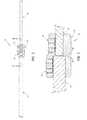
- FIG. 1is a perspective view of a spine rod connector assembly according to the present disclosure in which the rods are in a first configuration
- FIG. 2is a top view of the spine rod connector assembly of FIG. 1 ;
- FIG. 3is a cross-sectional view of the spine rod connector assembly of FIG. 2 ;
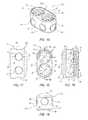
- FIG. 4is a perspective view of a spine rod connector assembly of FIG. 1 in which the rods are in a second configuration
- FIG. 5is a top view of the spine rod connector assembly of FIG. 4 ;
- FIG. 6is a cross-sectional view of the spines rod connector assembly of FIG. 5 ;
- FIG. 7is a perspective view of a spine rod connector assembly of FIG. 1 in which the rods are in a third configuration
- FIG. 8is a top view of the spine rod connector assembly of FIG. 7 ;
- FIG. 9is a cross-sectional view of the spine rod connector assembly of FIG. 8 ;
- FIG. 10is a perspective view of the spine rod connector of FIG. 1 ;
- FIG. 11is a top view of the spine rod connector of FIG. 1 ;
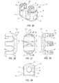
- FIG. 12is a side view of the spine rod connector of FIG. 1 ;
- FIG. 13is an end view of the spine rod connector of FIG. 1 ;
- FIG. 14is a cross-sectional view of the spine rod connector of FIG. 11 ;
- FIG. 15is a perspective view of another spine rod connector according to the present disclosure.
- FIG. 16is a top view of the spine rod connector of FIG. 15 ;
- FIG. 17is a side view of the spine rod connector of FIG. 15 ;
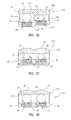
- FIG. 18is an end view of the spine rod connector of FIG. 15 ;
- FIG. 19is a cross-sectional view of the spine rod connector of FIG. 16 ;
- FIG. 20is a perspective view of another spine rod connector according to the present disclosure.
- FIG. 21is another perspective view of the spine rod connector of FIG. 20 ;
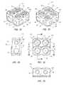
- FIG. 22is a top view of the spine rod connector of FIG. 20 ;
- FIG. 23is a side view of the spine rod connector of FIG. 20 ;
- FIG. 24is an end view of the spine rod connector of FIG. 20 ;
- FIG. 25is a cross-sectional view of the spine rod connector of FIG. 22 ;
- FIG. 26is a perspective view of another spine rod connector according to the present disclosure.
- FIG. 27is a top view of the spine rod connector of FIG. 26 ;
- FIG. 28is a side view of the spine rod connector of FIG. 26 ;
- FIG. 29is an end view of the spine rod connector of FIG. 26 ;
- FIG. 30is a cross-sectional view of the spine rod connector of FIG. 27 ;
- FIG. 31is a perspective view of another spine rod connector according to the present disclosure.
- FIG. 32is another perspective view of the spine rod connector of FIG. 31 ;
- FIG. 33is a top view of the spine rod connector of FIG. 31 ;
- FIG. 34is a side view of the spine rod connector of FIG. 31 ;
- FIG. 35is an end view of the spine rod connector of FIG. 31 ;
- FIG. 36is a cross-sectional view of the spine rod connector of FIG. 33 taken along cross-sectional indicator 36 - 36 ;
- FIG. 37is a cross-sectional view of the spine rod connector of FIG. 33 taken along cross-sectional indicator 37 - 37 ;
- FIG. 38is a cross-sectional view of the spine rod connector of FIG. 33 taken along cross-sectional indicator 38 - 38 .
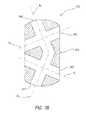
- FIG. 39is a cross-sectional view of another spine rod connector according to the present disclosure.
- the present disclosureis directed to a spine rod connector assembly that includes a spine rod connector configured to couple together a plurality of spinal rods used for treatment of a person's spine.
- the spine rod connectoris configured with a plurality of apertures or bores that are sized to receive the spine rods in various orientations relative to each other.
- the spine rod connectormay include at least one connecting device (e.g., a set screw or other fastener) that secures the spine rods to the spine rod connector.
- the connecting deviceprovides releasable coupling of the spine rods to the spine rod connector.
- the connecting deviceprovides a permanent connection between the spine rods and the spine rod connector.
- the spine rod connectorincludes at least two bores that are arranged and configured to allow non aligned spine rods to be coupled to the connector and at least one other bore that is arranged angled to the other bores. Inserting portions of the spine rods into the bores of the spine rod connector may result in a variety of relative orientations for the spine rods including, for example, in parallel, radially spaced apart orientations (i.e., side-by-side), in axially aligned orientations (i.e., end-to-end), angled orientations, or perpendicular orientations.
- the spine rod connectormay include different sized and shaped bores to receive various sized spine rods having a variety of cross-sectional shapes.
- the spine rod connectorincludes a first pair of bores arranged perpendicular to each other. The bores of the first pair of bores may each have a first diameter.
- the bores of a second pair of boresmay be arranged perpendicular to each other. The bores of the second pair of bore may each have a second diameter that is smaller than the first diameter.
- a set screw or other connecting devicemay be associated with each pair of bores. The set screws are operable to secure a spine rod in each of the pairs of bores.
- the spine rod connectorincludes three or more pairs of bores. A set screw or other connecting devices may be associated with each pair of bores and operable to couple a spine rod in each of the pairs of bores.
- the spine rod connector assembly 10includes a spine rod connector 12 and first and second spine rods 14 , 16 .
- Three different arrangements of the first and second spine rods 14 , 16 relative to each other and the spine rod connector 12are illustrated in FIGS. 1-9 .
- the first and second spine rods 14 , 16are arranged parallel with each other and radially spaced apart from each other (also referred to as laterally spaced apart or side-by-side).
- the spine rods 14 , 16are arranged in coaxial arrangement relative to each other.
- FIGS. 7-9the first and second spine rods 14 , 16 are arranged perpendicular to each other.
- the spine rod connector 12includes a base portion 20 , and first and second set screws 22 , 24 (see FIGS. 1-3 and 10 - 14 ).
- the base portion 20includes top and bottom surfaces 26 , 28 , front and rear surfaces 32 , 34 , and first and second side surfaces 36 , 38 .
- each of the pairs of surfaces 26 , 28 ; 32 , 34 ; 36 , 38are arranged generally perpendicular to each other.
- Any of the surfaces 26 , 28 , 32 , 34 , 36 , 38may be, for example, generally planer such as the general planer structure of surface 38 shown in FIG. 10 , curved or contour shaped such as the surface 34 shown in FIG.
- the step feature 30defines a relatively sharp change in thickness of the base portion 20 between an area surrounding the aperture 48 to the area surrounding the aperture 50 along the surface 26 .
- the step feature 30can be a gradual offset such as a ramp or curved surface extending from an area surrounding the aperture 48 to the area surrounding the aperture 50 along the surface 26 .
- Other configurations, shapes and sizesare possible for any one of the exterior surfaces of the base portion 20 .
- the descriptions of the connectors described hereingenerally refer to surfaces of the connector as having top, bottom, side, front, and/or rear surfaces.
- the connectorin fact may be cylindrical and/or spherical in construction. In such cases, the surface refers to a bore orientation on the connector.
- a spherical connectormay have, for example, two bores in a front surface of the sphere.
- the base portion 20 shown in FIGS. 1-14has a generally cubic shape with rectangular cross-sections. Many other shapes are possible for the base portion including, for example, generally spherical shapes, or the shapes that include fewer or greater than the six surface structure shown in FIGS. 1-14 .
- the base portion 20further includes first and second side rod apertures 40 , 42 , front and rear and apertures 44 , 46 , and first and second set screw apertures 48 , 50 .
- the first and second side rod apertures 40 , 42are shown having diameters D1, D2, respectively, that are different from each other.
- the front and rear end apertures 44 , 46have diameters D3, D4, respectively, that also are different from each other.
- the first and second set screw apertures 48 , 50have diameters D5, D6 that are substantially the same size. In other arrangements, any one of the diameters D1-D6 can be the same or different size.
- the first and second screw apertures 48 , 50include a plurality of internal threads 52 sized to mate with threads of the first and second set screws 22 , 24 .
- Each of the apertures 40 , 42 and 44 , 46are arranged in the same plane such that a central, longitudinal axis of each of the apertures 40 , 42 , 44 , 46 is coplanar (see plane P 1 in FIGS. 10 and 14 ).
- the spine rods 14 , 16are inserted into the apertures 40 , 42 , 44 , 46 in the various arrangements shown in FIGS. 3 , 6 and 9 , the spine rods 14 , 16 are also arranged coplanar.
- the first side rod aperture 40intersects with the front end aperture 44 .
- the first set screw aperture 48is arranged perpendicular to and intersects with the apertures 40 , 44 .
- second side rod aperture 42intersects with the rear end aperture 46 .
- the second set screw aperture 50is arranged perpendicular to and intersects the apertures 42 , 46 .
- the first and second set screws 22 , 24which are operable in the first and second set screw apertures 48 , 50 , respectively, may engage spine rods positioned in any of the apertures 40 , 42 , 44 , 46 .
- first side rod aperture 40 and front end aperture 44are arranged in different planes so that the longitudinal axis of the apertures 40 , 44 do not intersect.
- first set screw aperture 48may still be arranged to intersect both of the apertures 40 , 44 .
- the set screw 22may require additional length to the length illustrated in the figures to function in such an arrangement in which the apertures 40 , 44 are not arranged in the same plane. Similar aperture arrangements are possible for apertures 42 , 46 , 50 .
- the front and rear end apertures 44 , 46are arranged both coplanar and axially aligned with each other.
- the resultant arrangement of spine rods positioned in the apertures 44 , 46 as shown in FIGS. 4-6provides coaxial arrangement of the rods 14 , 16 .
- Other arrangements and orientations of the front and rear end apertures 44 , 46are possible.
- the front and rear end apertures 44 , 46may be arranged coplanar but not coaxial by being arranged at slight converging or diverging angles relative to each other.
- the front and rear end apertures 44 , 46can be non-coplanar and non-coaxially aligned so as to be arranged at converging or diverging angles in multiple planes.
- FIG. 39is a cross-sectional view illustrating an alternative spine rod connector 512 that includes a base portion 520 and a plurality of apertures 540 , 542 , 544 , 546 .
- the cross-section shown in FIG. 39can be taken through a plane of the spine rod connection 512 that intersects all of the apertures 540 , 542 , 544 , 546 , such as the plane P 1 shown in FIG. 10 .
- the apertures 540 , 542have axes A 1 , A 2 that are arranged at convergent/divergent angles relative to each other (i.e., non-parallel angle).
- the apertures 544 , 546have axes A 3 , A 4 that are also arranged at convergent/divergent angles relative to each other.
- the apertures 540 , 542 , 544 , 546are arranged coplanar.
- at least one of the apertures 540 , 542 , 544 , 546is non-coplanar with the other apertures 540 , 542 , 544 , 546 .
- at least one pair of apertures 540 , 542 or 544 , 546is arranged parallel and the other pair of apertures 540 , 542 , 544 , 546 is arranged at convergent/divergent angles.
- Other combinations of parallel, perpendicular, and convergent/divergent angled orientations for the apertures 540 , 542 , 544 , 546are possible.
- the step feature 30may be included on the top surface 26 to make constant a distance from the top surface 26 to the apertures 40 , 44 and 42 , 46 , respectively.
- the sets screws 22 , 24may have the same length and the same number of threads for operation in the first and second set screw apertures 48 , 50 . Further, there is the same amount of material of the connector member 12 included between the top surface 26 and each of the apertures 40 , 44 , and 42 , 46 .
- the first and second set screws 22 , 24each include a rod contact end 54 , an instrument recess 56 arranged on an opposite side from the rod contact end 54 , and a plurality of external threads 58 .
- the rod contact end 54may have various configurations or structures that permit close mating with the particular rod positioned in the apertures 40 , 42 , 46 , 48 .
- FIGS. 3 , 6 and 8illustrate various configurations for the rod contact end 54 .
- the rod contact end 54includes a generally planer surface for contact with the spine rods 14 , 16 .
- FIGS. 3 , 6 and 9show a rod contact end 54 having a contoured surfaces.
- the instrument recess 56may be structured to receive a portion of an instrument that is used to move the set screws 22 , 24 relative to the base portion 20 .
- the set screws 22 , 24may include recessed portions around an outer or peripheral surface for engagement by an instrument.
- the set screws 22 , 24may be replaced with other devices that are operable to secure the spine rods 14 , 16 to the base portion 20 .
- rivets, bolts, or other fastenersmay be used in place of or in combination with the set screws 22 , 24 to provide permanent or releasable contact with the spine rods 14 , 16 .
- the spine rod connector 112includes a base portion 120 that includes top and bottom surfaces 26 , 28 , front and rear surfaces 32 , 34 , and first and second side surfaces 36 , 38 .
- First and second side rod apertures 40 , 42extend between the first and second side surfaces 36 , 38 .
- the first and second side rod apertureshave first and second diameters D1, D2, respectively.
- the front and rear and apertures 44 , 46extend from the front surface 32 to the rear surface 34 .
- the front and rear end apertures 44 , 46have a diameter D3.
- First and second set screw apertures 48 , 50are defined in the top surface 26 and have a diameter D5.
- the set screw aperture 48 , 50have a plurality of internal threads 52 sized for threaded engagement with a pair of set screws (not shown), such as set screws 22 , 24 described above to reference to FIGS. 1-14 .
- the first and second side rod apertures 40 , 42have diameters D1, D2, respectively, that are substantially the same. In other arrangements, the diameters D1, D2 may be different.
- the diameter D3 of the front and rear end apertures 44 , 46is shown as a constant diameter but could have different diameters for each of the apertures 44 , 46 .
- the base portion 20can have a generally oval outer profile as shown in FIG. 16 .
- Some surfaces of the base portion 20may have a planer construction (e.g., the planar structure of top surface 26 ) or a contoured construction (e.g., the contoured construction of bottom surface 28 ) shown in FIG. 18 .
- the spine rod connector 112may be useful in coupling together a plurality of rods in various relative orientations, for example, in parallel, radially spaced apart orientations (i.e., side-by-side), in coaxial orientations (i.e., end-to-end), angled orientations, or perpendicular orientations.
- the spine rod connector 112is adapted for use with spine rods having the same diameter, while in other arrangements the spine rod connector 112 can be used with rods of different diameters.
- the spine rod connector 212includes a base portion 220 similar in construction with the base portion 20 shown and described above with reference to FIGS. 1-14 .
- the base portion 220further, includes front and rear aperture slots 98 , 99 .
- the front aperture slot 98provides an open pathway or slot extending from the top surface 26 and the first set screw aperture 48 to the front end aperture 44 .
- the rear aperture slot 99extends from the top surface and the second set screw aperture 50 to the rear end aperture 46 .
- the aperture slots 98 , 99may promote easier insertion of the spine rods 14 , 16 into the apertures 44 , 46 , respectively.
- first and second set screws 22 , 24are removed from the set screw apertures 48 , 50 while the spine rods 14 , 16 are inserted into the apertures 44 , 46 , respectively.
- the set screws 22 , 24may then be inserted into the set screw apertures 48 , 50 in a step that follows insertion of the spine rods 14 , 16 into the base portion 20 .
- FIGS. 26-30illustrate another example spine rod connector 312 that is a variation of the spine rod connectors 112 , 212 described above.
- the spine rod connector 312includes a base portion 320 .
- the base portion 320includes a pair of side aperture slots 398 , 399 .
- the side apertures slots 398 , 399extend from the top surface 26 to the first and second side rod apertures 40 , 42 .
- the side apertures slot 398 , 399also extend from the first side surface 36 to the second side surface 38 and extend through the first and second set screw apertures 48 , 50 .
- the side apertures slots 398 , 399extend only from the first side surface 36 to one of the set screw apertures 48 , 50 , or extend only from the second side surface 38 to one of the set screw apertures 48 , 50 .
- the base portion 320may further include front and rear end apertures 44 , 46 .
- at least one of the front and rear end apertures 44 , 46are not included.
- the apertures 40 , 42 , 44 , 46may have different sizes and shapes from each other to accommodate different spine rod sizes and cross-sectional shapes.
- at least one of the apertures 40 , 42 , 44 , 46can have an elliptical, hexagonal, rectangular, or other non-circular cross-sectional shape as shown in broken lines around apertures 42 and 46 in FIGS. 10 and 13 .
- the spine rod connector 412includes a base portion 420 having more than two pairs of rod apertures.
- the base portion 420is essentially a combination of two base portions 20 coupled in a side-by-side arrangement.
- the base portion 420includes the first and second side rod apertures 40 , 42 , first front and rear end apertures 44 , 46 , and first and second set screw apertures 48 , 50 .
- the first side rod aperture 40 and first front end aperture 44are arranged as a pair of rod apertures that intersect, and the first set screw aperture 48 is open to the intersection of the apertures 40 , 44 .
- the second side rod aperture 42 and first rear end aperture 46are arranged as a pair of rod apertures that is intersected, and the second set screw aperture 50 is open to the intersection of the apertures 42 , 46 .
- the base portion 420may further include a second front end aperture 94 and a second rear end aperture 96 that intersect with the first and second side rod apertures 40 , 42 , respectively. Additional third and fourth set screw apertures 90 , 92 are open to the intersection of with the second front and rear end apertures 94 , 96 with the first ands second side rod apertures 40 , 42 , respectively.
- the second front and rear end apertures 94 , 96have seventh and eighth diameters D7, D8, respectively.
- FIGS. 31-38The arrangement of apertures shown in FIGS. 31-38 is merely exemplary of the numerous combinations of apertures and set screws that are possible.
- the apertures 40 , 44 , 94have the same diameter, and the apertures 42 , 46 , 96 have the same diameter.
- any one of the aperture 40 , 42 , 44 , 46 , 94 , 96may have a different diameter from any of the other apertures 40 , 42 , 44 , 46 , 94 , 96 .
- any of the configurations described above with reference to FIGS. 1-30are possible with the spine rod connector 412 .
- spine rod connector possibilitiesinclude, for example, two of the spine rod connectors 12 , 112 , 212 , 312 arranged with the bottom surfaces 28 facing each other rather than the side surfaces facing each other as shown in FIGS. 31-38 .
- more than two of the spine rod connectors 12 , 112 , 212 , 312may be coupled together in various configurations to meet the spine rod orientations needed for treating a particular patient.
Landscapes
- Health & Medical Sciences (AREA)
- Orthopedic Medicine & Surgery (AREA)
- Life Sciences & Earth Sciences (AREA)
- Surgery (AREA)
- Neurology (AREA)
- Heart & Thoracic Surgery (AREA)
- Engineering & Computer Science (AREA)
- Biomedical Technology (AREA)
- Nuclear Medicine, Radiotherapy & Molecular Imaging (AREA)
- Medical Informatics (AREA)
- Molecular Biology (AREA)
- Animal Behavior & Ethology (AREA)
- General Health & Medical Sciences (AREA)
- Public Health (AREA)
- Veterinary Medicine (AREA)
- Surgical Instruments (AREA)
Abstract
Description
Claims (22)
Priority Applications (1)
| Application Number | Priority Date | Filing Date | Title |
|---|---|---|---|
| US12/393,980US8998961B1 (en) | 2009-02-26 | 2009-02-26 | Spinal rod connector and methods |
Applications Claiming Priority (1)
| Application Number | Priority Date | Filing Date | Title |
|---|---|---|---|
| US12/393,980US8998961B1 (en) | 2009-02-26 | 2009-02-26 | Spinal rod connector and methods |
Publications (1)
| Publication Number | Publication Date |
|---|---|
| US8998961B1true US8998961B1 (en) | 2015-04-07 |
Family
ID=52745055
Family Applications (1)
| Application Number | Title | Priority Date | Filing Date |
|---|---|---|---|
| US12/393,980Expired - Fee RelatedUS8998961B1 (en) | 2009-02-26 | 2009-02-26 | Spinal rod connector and methods |
Country Status (1)
| Country | Link |
|---|---|
| US (1) | US8998961B1 (en) |
Cited By (41)
| Publication number | Priority date | Publication date | Assignee | Title |
|---|---|---|---|---|
| US20130294817A1 (en)* | 2010-12-09 | 2013-11-07 | Fq Ip Ab | Locking device and method for fixation of components to tubes |
| US20140303674A1 (en)* | 2011-11-18 | 2014-10-09 | Orthopaedic International, Inc. | Parallel rod connector |
| US20150133933A1 (en)* | 2011-09-15 | 2015-05-14 | Stryker Trauma Sa | Rod coupler with variable ankle position |
| US20160302929A1 (en)* | 2015-04-15 | 2016-10-20 | FreeseTEC Corporation | Spinal fusion containment system |
| US20160361092A1 (en)* | 2008-11-11 | 2016-12-15 | K2M, Inc. | Growth directed vertebral fixation system with distractible connector(s) and apical control |
| US9579126B2 (en) | 2008-02-02 | 2017-02-28 | Globus Medical, Inc. | Spinal rod link reducer |
| US20170100167A1 (en)* | 2012-05-09 | 2017-04-13 | Coligne Ag | Iliac connector, connector head, spinal fixation system and method of stabilizing a spine |
| US20170128107A1 (en)* | 2014-12-16 | 2017-05-11 | Jeremy Stevan Alsup | Rod connector with swivel collet |
| US9848918B2 (en) | 2005-11-21 | 2017-12-26 | DePuy Synthes Products, Inc. | Polyaxial bone anchors with increased angulation |
| US9974571B2 (en) | 2008-09-12 | 2018-05-22 | DePuy Synthes Products, Inc. | Spinal stabilizing and guiding fixation system |
| US9980755B2 (en) | 2016-03-29 | 2018-05-29 | Globus Medical, Inc. | Revision connectors, systems, and methods thereof |
| US20180228518A1 (en)* | 2017-02-10 | 2018-08-16 | Medos International Sarl | Tandem rod connectors and related methods |
| US10070895B2 (en) | 2015-09-30 | 2018-09-11 | Amendia, Inc. | Dual tulip assembly |
| US10136923B2 (en) | 2007-07-20 | 2018-11-27 | DePuy Synthes Products, Inc. | Polyaxial bone fixation element |
| US10154859B2 (en) | 2008-09-29 | 2018-12-18 | DePuy Synthes Products, Inc. | Polyaxial bottom-loading screw and rod assembly |
| US20190090907A1 (en)* | 2009-04-15 | 2019-03-28 | DePuy Synthes Products, Inc. | Revision connector for spinal constructs |
| US10307185B2 (en) | 2016-03-29 | 2019-06-04 | Globus Medical, Inc. | Revision connectors, systems, and methods thereof |
| US10321939B2 (en) | 2016-05-18 | 2019-06-18 | Medos International Sarl | Implant connectors and related methods |
| US10383663B2 (en) | 2016-03-29 | 2019-08-20 | Globus Medical, Inc. | Revision connectors, systems and methods thereof |
| US10398476B2 (en) | 2016-12-13 | 2019-09-03 | Medos International Sàrl | Implant adapters and related methods |
| US10405892B2 (en) | 2008-11-03 | 2019-09-10 | DePuy Synthes Products, Inc. | Uni-planer bone fixation assembly |
| US10492835B2 (en) | 2016-12-19 | 2019-12-03 | Medos International Sàrl | Offset rods, offset rod connectors, and related methods |
| US10517647B2 (en) | 2016-05-18 | 2019-12-31 | Medos International Sarl | Implant connectors and related methods |
| US10561454B2 (en) | 2017-03-28 | 2020-02-18 | Medos International Sarl | Articulating implant connectors and related methods |
| US10624679B2 (en) | 2016-03-29 | 2020-04-21 | Globus Medical, Inc. | Revision connectors, systems and methods thereof |
| US10687859B2 (en) | 2016-07-15 | 2020-06-23 | Stryker European Holdings I, Llc | Spinal fixation assembly |
| US10786285B2 (en) | 2016-06-06 | 2020-09-29 | Stryker European Holdings I, Llc | Paraxial revision rod-to-rod connector |
| US10966761B2 (en) | 2017-03-28 | 2021-04-06 | Medos International Sarl | Articulating implant connectors and related methods |
| US11006978B2 (en) | 2009-06-17 | 2021-05-18 | DePuy Synthes Products, Inc. | Revision connector for spinal constructs |
| US20210145482A1 (en)* | 2009-05-15 | 2021-05-20 | Stryker European Operations Holdings Llc | Fixation Clamp |
| US11026724B2 (en)* | 2016-12-02 | 2021-06-08 | Kyoung Gee AHN | Fixing rod connecting device |
| WO2021140498A1 (en)* | 2020-03-03 | 2021-07-15 | Inno4Spine Ag | Spinal bone fastener assembly |
| US11076890B2 (en) | 2017-12-01 | 2021-08-03 | Medos International Sàrl | Rod-to-rod connectors having robust rod closure mechanisms and related methods |
| EP3884891A2 (en) | 2020-03-25 | 2021-09-29 | Aesculap AG | Surgical connecting device and surgical connection system |
| US11284924B1 (en) | 2020-12-16 | 2022-03-29 | Warsaw Orthopedic, Inc | Adjustable spinal implant, system and method |
| US11337734B2 (en) | 2019-05-22 | 2022-05-24 | Nuvasive, Inc. | Posterior spinal fixation screws |
| US11350969B1 (en) | 2021-02-02 | 2022-06-07 | Warsaw Orthopedic, Inc. | Rotatable spinal implant, system, and method |
| US20240138574A1 (en)* | 2020-10-27 | 2024-05-02 | PrivaSeat, LLC | Retrofitting apparatus for a chair that extends around sides of an upper body portion of a user seated in the chair |
| US12161235B2 (en)* | 2020-10-27 | 2024-12-10 | PrivaSeat, LLC | Retrofitting apparatus for a chair that extends around sides of an upper body portion of a user seated in the chair |
| US20250120749A1 (en)* | 2023-10-17 | 2025-04-17 | Nexus Spine, LLC | Add-on coupler for medical implant revision |
| US12336741B2 (en)* | 2023-03-14 | 2025-06-24 | Warsaw Orthopedic, Inc. | Surgical system and methods of use |
Citations (230)
| Publication number | Priority date | Publication date | Assignee | Title |
|---|---|---|---|---|
| US2249658A (en)* | 1940-06-07 | 1941-07-15 | Theodore B Kemner | Scaffold |
| US2970798A (en)* | 1956-10-23 | 1961-02-07 | Central Scient Co | Laboratory clamps |
| US4294561A (en)* | 1978-05-24 | 1981-10-13 | Pentabloc, Ltd. | Jointing member for frame systems |
| US4326354A (en)* | 1977-03-24 | 1982-04-27 | Hagberg Carl E | Recreational kit for constructing objects |
| US4569338A (en) | 1984-02-09 | 1986-02-11 | Edwards Charles C | Sacral fixation device |
| US4573459A (en)* | 1983-08-25 | 1986-03-04 | Litton Bruce W | Thumb and finger extension device |
| US4628921A (en)* | 1983-10-03 | 1986-12-16 | Mauricio Rousso | Unilateral external fixation system for small bones |
| US4887596A (en) | 1988-03-02 | 1989-12-19 | Synthes (U.S.A.) | Open backed pedicle screw |
| US4946458A (en) | 1986-04-25 | 1990-08-07 | Harms Juergen | Pedicle screw |
| US5000165A (en) | 1989-05-15 | 1991-03-19 | Watanabe Robert S | Lumbar spine rod fixation system |
| US5067955A (en) | 1989-04-13 | 1991-11-26 | Societe De Fabrication De Material Orthopedique | Vertebral implant for osteosynthesis device |
| US5084049A (en) | 1989-02-08 | 1992-01-28 | Acromed Corporation | Transverse connector for spinal column corrective devices |
| US5120171A (en) | 1990-11-27 | 1992-06-09 | Stuart Surgical | Bone screw with improved threads |
| US5133717A (en)* | 1990-02-08 | 1992-07-28 | Societe De Fabrication De Material Orthopedique Sofamor | Sacral support saddle for a spinal osteosynthesis device |
| US5147360A (en) | 1990-02-19 | 1992-09-15 | Societe De Fabrication De Materiel Orthopedique | Osteosynthesis device for the correction of spinal curvatures |
| US5190543A (en) | 1990-11-26 | 1993-03-02 | Synthes (U.S.A.) | Anchoring device |
| US5207678A (en) | 1989-07-20 | 1993-05-04 | Prufer | Pedicle screw and receiver member therefore |
| US5226766A (en) | 1990-11-27 | 1993-07-13 | Stuart Surgical | Bone screw with improved threads |
| US5275600A (en) | 1992-10-05 | 1994-01-04 | Zimmer, Inc. | Telescoping rod to rod coupler for a spinal system |
| US5312405A (en) | 1992-07-06 | 1994-05-17 | Zimmer, Inc. | Spinal rod coupler |
| US5312404A (en) | 1990-07-24 | 1994-05-17 | Acromed Corporation | Spinal column retaining apparatus |
| FR2693365B1 (en) | 1992-07-13 | 1994-11-10 | Vignaud Jean Louis | Spinal instrumentation with adjustable rod. |
| US5374267A (en) | 1992-02-17 | 1994-12-20 | Acromed B.V. | Device for fixing at least a part of the human cervical and/or thoracic vertebral column |
| US5380325A (en) | 1992-11-06 | 1995-01-10 | Biomat | Osteosynthesis device for spinal consolidation |
| US5382248A (en) | 1992-09-10 | 1995-01-17 | H. D. Medical, Inc. | System and method for stabilizing bone segments |
| US5387212A (en) | 1993-01-26 | 1995-02-07 | Yuan; Hansen A. | Vertebral locking and retrieving system with central locking rod |
| US5395371A (en) | 1991-07-15 | 1995-03-07 | Danek Group, Inc. | Spinal fixation system |
| US5429639A (en) | 1993-05-17 | 1995-07-04 | Tornier S.A. | Spine fixator for holding a vertebral column |
| US5437669A (en) | 1993-08-12 | 1995-08-01 | Amei Technologies Inc. | Spinal fixation systems with bifurcated connectors |
| US5437671A (en) | 1992-03-10 | 1995-08-01 | Zimmer, Inc. | Perpendicular rod connector for spinal fixation device |
| US5466237A (en) | 1993-11-19 | 1995-11-14 | Cross Medical Products, Inc. | Variable locking stabilizer anchor seat and screw |
| US5468241A (en) | 1988-02-18 | 1995-11-21 | Howmedica Gmbh | Support device for the human vertebral column |
| US5474555A (en) | 1990-04-26 | 1995-12-12 | Cross Medical Products | Spinal implant system |
| US5486174A (en) | 1993-02-24 | 1996-01-23 | Soprane S.A. | Fastener for the osteosynthesis of the spinal column |
| US5487742A (en) | 1990-03-08 | 1996-01-30 | Sofamore Danek Group | Transverse fixation device for a spinal osteosynthesis system |
| US5492442A (en) | 1990-11-27 | 1996-02-20 | National Medical Specialty, Inc. | Bone screw with improved threads |
| US5499983A (en) | 1994-02-23 | 1996-03-19 | Smith & Nephew Richards, Inc. | Variable angle spinal screw |
| US5505731A (en) | 1993-09-01 | 1996-04-09 | Tornier Sa | Screw for lumbar-sacral fixator |
| US5507745A (en) | 1994-02-18 | 1996-04-16 | Sofamor, S.N.C. | Occipito-cervical osteosynthesis instrumentation |
| US5514132A (en) | 1993-01-19 | 1996-05-07 | Jbs S.A. | Spinal osteosynthesis device |
| US5520689A (en) | 1992-06-04 | 1996-05-28 | Synthes (U.S.A.) | Osteosynthetic fastening device |
| US5522816A (en) | 1994-03-09 | 1996-06-04 | Acromed Corporation | Transverse connection for spinal column corrective devices |
| US5527314A (en)* | 1993-01-04 | 1996-06-18 | Danek Medical, Inc. | Spinal fixation system |
| US5531746A (en) | 1995-04-13 | 1996-07-02 | Fastenetix, L.L.C. | Posterior spinal polyaxial locking lateral mass screw plate assembly |
| US5536268A (en) | 1992-12-23 | 1996-07-16 | Plus Endoprothetik Ag | System for osteosynthesis at the vertebral column, connecting element for such a system and tool for its placement and removal |
| US5542946A (en) | 1994-05-27 | 1996-08-06 | Sofamor S.N.C. | Hook for an occipito-cervical rod or plate of an occipito-cervical osteosynthesis instrumentation |
| US5549608A (en) | 1995-07-13 | 1996-08-27 | Fastenetix, L.L.C. | Advanced polyaxial locking screw and coupling element device for use with rod fixation apparatus |
| US5554157A (en) | 1995-07-13 | 1996-09-10 | Fastenetix, L.L.C. | Rod securing polyaxial locking screw and coupling element assembly |
| US5569246A (en) | 1993-12-28 | 1996-10-29 | Asahi Kogaku Kogyo Kabushiki Kaisha | Fixing instrument for spinal fusion members |
| US5569248A (en) | 1992-03-17 | 1996-10-29 | Danek Medical, Inc. | Apparatus for subcutaneous suprafascial pedicular internal fixation |
| US5569247A (en) | 1995-03-27 | 1996-10-29 | Smith & Nephew Richards, Inc. | Enhanced variable angle bone bolt |
| FR2734471A1 (en) | 1995-05-24 | 1996-11-29 | Implants Orthopediques Toutes | Spinal fixator retaining screw |
| US5584834A (en) | 1995-07-13 | 1996-12-17 | Fastenetix, L.L.C. | Polyaxial locking screw and coupling element assembly for use with side loading rod fixation apparatus |
| US5586984A (en) | 1995-07-13 | 1996-12-24 | Fastenetix, L.L.C. | Polyaxial locking screw and coupling element assembly for use with rod fixation apparatus |
| US5591166A (en) | 1995-03-27 | 1997-01-07 | Smith & Nephew Richards, Inc. | Multi angle bone bolt |
| US5591165A (en) | 1992-11-09 | 1997-01-07 | Sofamor, S.N.C. | Apparatus and method for spinal fixation and correction of spinal deformities |
| US5601552A (en) | 1994-03-18 | 1997-02-11 | Sofamor, S.N.C. | Fixing device for a rigid transverse connection device between rods of a spinal osteosynthesis system |
| US5607425A (en) | 1993-10-08 | 1997-03-04 | Rogozinski; Chaim | Apparatus, method and system for the treatment of spinal conditions |
| US5628740A (en) | 1993-12-23 | 1997-05-13 | Mullane; Thomas S. | Articulating toggle bolt bone screw |
| US5634925A (en) | 1993-02-19 | 1997-06-03 | Alphatec Manufacturing, Inc. | Apparatus and method for spinal fixation system |
| US5643264A (en) | 1995-09-13 | 1997-07-01 | Danek Medical, Inc. | Iliac screw |
| US5653708A (en) | 1992-12-28 | 1997-08-05 | Advanced Spine Fixation Systems, Inc. | Cervical spine rod fixation system |
| US5662653A (en) | 1996-02-22 | 1997-09-02 | Pioneer Laboratories, Inc. | Surgical rod-to-bone attachment |
| US5667506A (en) | 1992-10-22 | 1997-09-16 | Danek Medical, Inc. | Spinal rod transverse connector for supporting vertebral fixation elements |
| US5669910A (en) | 1996-01-02 | 1997-09-23 | Pioneer Laboratories, Inc. | Crosslink for implantable rods |
| US5669911A (en) | 1995-04-13 | 1997-09-23 | Fastenetix, L.L.C. | Polyaxial pedicle screw |
| US5672176A (en) | 1995-03-15 | 1997-09-30 | Biedermann; Lutz | Anchoring member |
| US5683390A (en) | 1994-02-22 | 1997-11-04 | Howmedica Gmbh | Correcting a spinal column |
| US5688272A (en) | 1995-03-30 | 1997-11-18 | Danek Medical, Inc. | Top-tightening transverse connector for a spinal fixation system |
| US5693053A (en) | 1995-10-19 | 1997-12-02 | Sdgi Holdings, Inc. | Variable angle and transitional linking member |
| US5702395A (en) | 1992-11-10 | 1997-12-30 | Sofamor S.N.C. | Spine osteosynthesis instrumentation for an anterior approach |
| US5702452A (en)* | 1995-01-23 | 1997-12-30 | Sofamor S.N.C. | Spinal osteosynthesis device with median hook and vertebral anchoring support |
| FR2740674B1 (en) | 1995-11-07 | 1998-01-23 | Stryker France Sa | DEVICE FOR FIXING A ROD TO SACRUM IN OSTEOSYNTHESIS OF THE RACHIS |
| US5716355A (en) | 1995-04-10 | 1998-02-10 | Sofamor Danek Group, Inc. | Transverse connection for spinal rods |
| US5725528A (en) | 1997-02-12 | 1998-03-10 | Third Millennium Engineering, Llc | Modular polyaxial locking pedicle screw |
| US5728098A (en) | 1996-11-07 | 1998-03-17 | Sdgi Holdings, Inc. | Multi-angle bone screw assembly using shape-memory technology |
| US5733286A (en) | 1997-02-12 | 1998-03-31 | Third Millennium Engineering, Llc | Rod securing polyaxial locking screw and coupling element assembly |
| US5735851A (en) | 1996-10-09 | 1998-04-07 | Third Millennium Engineering, Llc | Modular polyaxial locking pedicle screw |
| US5738685A (en) | 1993-05-18 | 1998-04-14 | Schafer Micomed Gmbh | Osteosynthesis device |
| US5752955A (en) | 1995-10-30 | 1998-05-19 | Fastenetix, L.L.C. | Sliding shaft variable length cross-link device for use with dual rod apparatus |
| US5752957A (en) | 1997-02-12 | 1998-05-19 | Third Millennium Engineering, Llc | Polyaxial mechanism for use with orthopaedic implant devices |
| US5776135A (en) | 1996-12-23 | 1998-07-07 | Third Millennium Engineering, Llc | Side mounted polyaxial pedicle screw |
| US5782833A (en) | 1996-12-20 | 1998-07-21 | Haider; Thomas T. | Pedicle screw system for osteosynthesis |
| US5785711A (en) | 1997-05-15 | 1998-07-28 | Third Millennium Engineering, Llc | Polyaxial pedicle screw having a through bar clamp locking mechanism |
| US5800548A (en) | 1996-03-05 | 1998-09-01 | Bruno Franck | Device for transverse spinal connection |
| US5810819A (en) | 1997-05-15 | 1998-09-22 | Spinal Concepts, Inc. | Polyaxial pedicle screw having a compression locking rod gripping mechanism |
| US5814046A (en) | 1992-11-13 | 1998-09-29 | Sofamor S.N.C. | Pedicular screw and posterior spinal instrumentation |
| US5863293A (en) | 1996-10-18 | 1999-01-26 | Spinal Innovations | Spinal implant fixation assembly |
| US5879350A (en) | 1996-09-24 | 1999-03-09 | Sdgi Holdings, Inc. | Multi-axial bone screw assembly |
| US5882350A (en) | 1995-04-13 | 1999-03-16 | Fastenetix, Llc | Polyaxial pedicle screw having a threaded and tapered compression locking mechanism |
| US5891145A (en) | 1997-07-14 | 1999-04-06 | Sdgi Holdings, Inc. | Multi-axial screw |
| US5910142A (en) | 1998-10-19 | 1999-06-08 | Bones Consulting, Llc | Polyaxial pedicle screw having a rod clamping split ferrule coupling element |
| US5947966A (en) | 1995-06-06 | 1999-09-07 | Sdgi Holdings, Inc. | Device for linking adjacent rods in spinal instrumentation |
| US5964760A (en) | 1996-10-18 | 1999-10-12 | Spinal Innovations | Spinal implant fixation assembly |
| US5980523A (en) | 1998-01-08 | 1999-11-09 | Jackson; Roger | Transverse connectors for spinal rods |
| US5984922A (en) | 1993-07-09 | 1999-11-16 | Mckay; Douglas William | Spinal fixation device and method |
| US5989251A (en) | 1998-06-17 | 1999-11-23 | Surgical Dynamics, Inc. | Apparatus for spinal stabilization |
| US5989250A (en) | 1996-10-24 | 1999-11-23 | Spinal Concepts, Inc. | Method and apparatus for spinal fixation |
| US5989254A (en) | 1997-05-20 | 1999-11-23 | Katz; Akiva Raphael | Pedicle screw assembly |
| US6004332A (en) | 1997-05-01 | 1999-12-21 | Yoon; Inbae | Suturing instrument with multiple rotatably mounted offset needle holders and method of using the same |
| US6015409A (en) | 1994-05-25 | 2000-01-18 | Sdgi Holdings, Inc. | Apparatus and method for spinal fixation and correction of spinal deformities |
| US6074393A (en) | 1996-06-07 | 2000-06-13 | Robert Reid, Inc. | Bone fixing screws |
| US6083226A (en) | 1998-04-22 | 2000-07-04 | Fiz; Daniel | Bone fixation device and transverse linking bridge |
| US6090111A (en) | 1998-06-17 | 2000-07-18 | Surgical Dynamics, Inc. | Device for securing spinal rods |
| US6096039A (en) | 1998-05-13 | 2000-08-01 | Howmedica Gmbh | Means for interconnecting two spaced elongated rods of a human spine implant |
| US6110173A (en) | 1998-09-15 | 2000-08-29 | Advanced Spine Fixation Systems, Inc. | Transverse connector for spinal fixation systems |
| US6113600A (en) | 1995-06-06 | 2000-09-05 | Denek Medical, Inc. | Device for linking adjacent rods in spinal instrumentation |
| US6113601A (en) | 1998-06-12 | 2000-09-05 | Bones Consulting, Llc | Polyaxial pedicle screw having a loosely coupled locking cap |
| US6132430A (en) | 1996-10-24 | 2000-10-17 | Spinal Concepts, Inc. | Spinal fixation system |
| WO2000076413A1 (en) | 1999-06-14 | 2000-12-21 | Scient'x | Implant for osteosynthesis device in particular of the backbone |
| US6171311B1 (en) | 1996-10-18 | 2001-01-09 | Marc Richelsoph | Transverse connector |
| US6179838B1 (en) | 1998-02-24 | 2001-01-30 | Daniel Fiz | Bone fixation arrangements and method |
| US6183472B1 (en) | 1998-04-09 | 2001-02-06 | Howmedica Gmbh | Pedicle screw and an assembly aid therefor |
| US6217578B1 (en) | 1999-10-19 | 2001-04-17 | Stryker Spine S.A. | Spinal cross connector |
| US6224598B1 (en) | 2000-02-16 | 2001-05-01 | Roger P. Jackson | Bone screw threaded plug closure with central set screw |
| US6234705B1 (en) | 1999-04-06 | 2001-05-22 | Synthes (Usa) | Transconnector for coupling spinal rods |
| US6238396B1 (en) | 1999-10-07 | 2001-05-29 | Blackstone Medical, Inc. | Surgical cross-connecting apparatus and related methods |
| US6241731B1 (en) | 1998-08-11 | 2001-06-05 | Daniel Fiz | Plate and screw assembly for fixing bones |
| FR2789293B1 (en) | 1999-02-10 | 2001-06-22 | Emmanuel Bockx | VERTEBRAL STABILITY DEVICE |
| US6283967B1 (en) | 1999-12-17 | 2001-09-04 | Synthes (U.S.A.) | Transconnector for coupling spinal rods |
| US6299614B1 (en) | 1999-03-29 | 2001-10-09 | Signus Medizintechnik Gmbh | Device for stabilizing vertebra bodies of the spinal column |
| US6302882B1 (en) | 1997-05-15 | 2001-10-16 | Surgical Dynamics, Inc. | Transverse rod connector clip |
| US6325802B1 (en) | 1992-08-12 | 2001-12-04 | Synthes (U.S.A.) | Spinal fixation element |
| WO2001097701A1 (en) | 2000-06-22 | 2001-12-27 | Emmanuel Bockx | Device for adjustable fixing of a tie rod using at least a pedicular screw for vertebral stability |
| US20020007183A1 (en) | 1998-07-06 | 2002-01-17 | Solco Surgical Instruments Co., Ltd. | Spine fixing apparatus |
| US20020010467A1 (en) | 2000-07-22 | 2002-01-24 | Corin Spinal Systems Limited | Pedicle attachment assembly |
| US20020032442A1 (en) | 2000-06-09 | 2002-03-14 | Moti Altarac | Adjustable transverse connector for use with a spinal implant system |
| US20020040223A1 (en) | 2000-09-22 | 2002-04-04 | Showa Ika Kohgyo Co., Ltd. | Bone connecting tool and connecting member thereof |
| US6368320B1 (en) | 1997-12-09 | 2002-04-09 | (Dimso) Distribution Medicale Du Sud-Ouest | Connector for backbone osteosynthesis device |
| US6368321B1 (en) | 2000-12-04 | 2002-04-09 | Roger P. Jackson | Lockable swivel head bone screw |
| US20020052603A1 (en) | 1999-03-30 | 2002-05-02 | Surgical Dynamics, Inc. | Apparatus for spinal stabilization |
| US20020068937A1 (en)* | 2000-12-01 | 2002-06-06 | Kuntz Charles A. | Method and device to correct instability of hinge joints |
| US6402752B2 (en) | 2000-02-07 | 2002-06-11 | Ulrich Gmbh & Co. Kg | Polyaxial pedicle-screw |
| US6413257B1 (en) | 1997-05-15 | 2002-07-02 | Surgical Dynamics, Inc. | Clamping connector for spinal fixation systems |
| US6413258B1 (en) | 1999-08-12 | 2002-07-02 | Osteotech, Inc. | Rod-to-rod coupler |
| US6423064B1 (en) | 1999-09-15 | 2002-07-23 | Ulrich Gmbh & Co. Kg | Orthopaedic screw variable angle connection to a longitudinal support |
| US6432108B1 (en) | 2000-01-24 | 2002-08-13 | Depuy Orthopaedics, Inc. | Transverse connector |
| US20020111625A1 (en) | 2001-02-12 | 2002-08-15 | Marc Richelsoph | Rod to rod connector |
| US6440137B1 (en) | 2000-04-18 | 2002-08-27 | Andres A. Horvath | Medical fastener cap system |
| US6440132B1 (en) | 2000-05-24 | 2002-08-27 | Roger P. Jackson | Open head bone screw closure with threaded boss |
| US6451021B1 (en) | 2001-02-15 | 2002-09-17 | Third Millennium Engineering, Llc | Polyaxial pedicle screw having a rotating locking element |
| US20020138077A1 (en) | 2001-03-26 | 2002-09-26 | Ferree Bret A. | Spinal alignment apparatus and methods |
| US20020143330A1 (en) | 2001-04-02 | 2002-10-03 | Endius Incorporated | Polyaxial transverse connector |
| US6478798B1 (en) | 2001-05-17 | 2002-11-12 | Robert S. Howland | Spinal fixation apparatus and methods for use |
| US20020169450A1 (en) | 2001-04-24 | 2002-11-14 | Co-Ligne Ag | Instrumentation for stabilizing certain vertebrae of the spine |
| US20020169448A1 (en) | 1999-07-01 | 2002-11-14 | Vanacker Gerard M. | Connector for an osteosynthesis system intended to provide a connection between two rods of a spinal osteosynthesis system, osteosynthesis system using such a connector, and method of implanting such an osteosynthesis system |
| US6482207B1 (en) | 2000-07-13 | 2002-11-19 | Fastenetix, Llc | Efficient assembling modular locking pedicle screw |
| US6488681B2 (en) | 2001-01-05 | 2002-12-03 | Stryker Spine S.A. | Pedicle screw assembly |
| US20030032959A1 (en)* | 1999-12-10 | 2003-02-13 | Chung-Chun Yeh | Spinal fixation hook and spinal fixation retrieval device |
| US6520444B1 (en) | 1997-08-27 | 2003-02-18 | Mueller Lothar | Toolbox containing a least one cable reel |
| US6524310B1 (en) | 2000-08-18 | 2003-02-25 | Blackstone Medical, Inc. | Surgical cross-connecting apparatus having locking lever |
| US20030045874A1 (en) | 2001-08-31 | 2003-03-06 | Thomas James C. | Transverse connector assembly for spine fixation system |
| US6533790B1 (en) | 2000-07-27 | 2003-03-18 | Yuehuei H An | Self-guided pedical screw |
| US6540748B2 (en) | 1999-09-27 | 2003-04-01 | Blackstone Medical, Inc. | Surgical screw system and method of use |
| US6540749B2 (en) | 2001-02-17 | 2003-04-01 | Bernd Schäfer | Bone screw |
| US6547789B1 (en) | 1999-07-02 | 2003-04-15 | Sulzer Orthopedics Ltd. | Holding apparatus for the spinal column |
| US20030078580A1 (en) | 2000-04-28 | 2003-04-24 | Hideo Shitoto | Spinal-rod connecting apparatus and a connector thereof |
| US6554834B1 (en) | 1999-10-07 | 2003-04-29 | Stryker Spine | Slotted head pedicle screw assembly |
| US6565566B1 (en) | 2000-03-22 | 2003-05-20 | Spinal Concepts, Inc. | Sacral screw assembly and method |
| US20030114853A1 (en) | 2001-10-12 | 2003-06-19 | Ian Burgess | Polyaxial cross connector |
| US6585740B2 (en) | 1998-11-26 | 2003-07-01 | Synthes (U.S.A.) | Bone screw |
| US20030125742A1 (en) | 1998-06-17 | 2003-07-03 | Howmedica Osteonics Corp. | Device for securing spinal rods |
| US6589243B1 (en) | 1998-09-18 | 2003-07-08 | Guy Viart | Posterior backbone osteosynthesis device |
| US6610062B2 (en) | 2000-02-16 | 2003-08-26 | Ebi, L.P. | Method and system for spinal fixation |
| US20030163132A1 (en) | 2002-02-27 | 2003-08-28 | Chin Kingsley Richard | Apparatus and method for spine fixation |
| US20030171751A1 (en) | 2002-02-20 | 2003-09-11 | Stephen Ritland | Pedicle screw connector apparatus and method |
| EP1354563A2 (en) | 2002-04-18 | 2003-10-22 | Spinal Innovations, Inc. | Screw and rod fixation assembly and device |
| US6645207B2 (en) | 2000-05-08 | 2003-11-11 | Robert A. Dixon | Method and apparatus for dynamized spinal stabilization |
| US6673073B1 (en) | 1999-11-29 | 2004-01-06 | Schaefer Bernd | Transverse connector |
| US20040015166A1 (en) | 2002-07-22 | 2004-01-22 | Gorek Josef E. | System and method for stabilizing the spine by securing spine stabilization rods in crossed disposition |
| US6685705B1 (en)* | 2000-10-23 | 2004-02-03 | Sdgi Holdings, Inc. | Six-axis and seven-axis adjustable connector |
| US20040049188A1 (en) | 2002-09-09 | 2004-03-11 | Depuy Acromed, Inc. | Snap-on spinal rod connector |
| US20040116928A1 (en) | 2002-10-28 | 2004-06-17 | Young J. Stewart | Multi-axial, cross-link connector system for spinal implants |
| US20040122425A1 (en) | 2002-09-12 | 2004-06-24 | Showa Ika Kohgyo Co., Ltd. | Rod fixing apparatus for vertebra connecting member |
| US20040133202A1 (en) | 2002-09-12 | 2004-07-08 | Showa Ika Kohgyo Co., Ltd. | Rod connector |
| US20040133203A1 (en) | 2002-10-28 | 2004-07-08 | Young J Stewart | Multi-axial, cross-link connector system for spinal implants |
| US20040143265A1 (en) | 2002-10-30 | 2004-07-22 | Landry Michael E. | Spinal stabilization systems and methods using minimally invasive surgical procedures |
| US20040153077A1 (en) | 2000-11-10 | 2004-08-05 | Lutz Biedermann | Bone screw |
| US20040176766A1 (en) | 2002-02-13 | 2004-09-09 | Shluzas Alan E. | Apparatus for connecting a longitudinal member to a bone portion |
| US20040181223A1 (en) | 2001-09-28 | 2004-09-16 | Stephen Ritland | Adjustable rod and connector device and method of use |
| US20040236330A1 (en) | 2003-05-22 | 2004-11-25 | Thomas Purcell | Variable angle spinal screw assembly |
| US20050010222A1 (en) | 2003-07-01 | 2005-01-13 | Cordaro Nicholas M. | Transverse connector system |
| US20050033295A1 (en) | 2003-08-08 | 2005-02-10 | Paul Wisnewski | Implants formed of shape memory polymeric material for spinal fixation |
| US6872208B1 (en) | 2000-10-06 | 2005-03-29 | Spinal Concepts, Inc. | Adjustable transverse connector |
| US20050080415A1 (en) | 2003-10-14 | 2005-04-14 | Keyer Thomas R. | Polyaxial bone anchor and method of spinal fixation |
| US20050080420A1 (en)* | 2003-08-20 | 2005-04-14 | Farris Robert A. | Multi-axial orthopedic device and system |
| US20050090821A1 (en) | 2003-10-22 | 2005-04-28 | Gregory Berrevoets | Crosslink for securing spinal rods |
| US6887241B1 (en) | 2000-10-06 | 2005-05-03 | Spinal Concepts, Inc. | Adjustable transverse connector with cam activated engagers |
| US20050107789A1 (en) | 2003-10-21 | 2005-05-19 | Endius Incorporated | Method for interconnecting longitudinal members extending along a spinal column |
| US6896677B1 (en) | 2003-12-11 | 2005-05-24 | A-Spine Holding Group Corp. | Rotary device for retrieving spinal column under treatment |
| US20050113830A1 (en) | 2003-11-24 | 2005-05-26 | Alan Rezach | Grommet assembly |
| US20050137594A1 (en) | 2002-02-04 | 2005-06-23 | Doubler Robert L. | Spinal fixation assembly |
| US20050143823A1 (en) | 2003-12-31 | 2005-06-30 | Boyd Lawrence M. | Dynamic spinal stabilization system |
| US20050149019A1 (en) | 2003-12-19 | 2005-07-07 | Sasing Jude L. | Transverse connector for rod-based spinal implants |
| US20050154390A1 (en) | 2003-11-07 | 2005-07-14 | Lutz Biedermann | Stabilization device for bones comprising a spring element and manufacturing method for said spring element |
| US20050177154A1 (en) | 2000-09-22 | 2005-08-11 | Missoum Moumene | Locking cap assembly for spinal fixation instrumentation |
| US20050187548A1 (en) | 2004-01-13 | 2005-08-25 | Butler Michael S. | Pedicle screw constructs for spine fixation systems |
| US20050192571A1 (en) | 2004-02-27 | 2005-09-01 | Custom Spine, Inc. | Polyaxial pedicle screw assembly |
| US20050203515A1 (en) | 2003-12-30 | 2005-09-15 | Thomas Doherty | Bone anchor assemblies |
| US20050228377A1 (en) | 2004-04-07 | 2005-10-13 | Depuy Spine, Inc. | Spinal cross-connectors |
| US6974460B2 (en) | 2001-09-14 | 2005-12-13 | Stryker Spine | Biased angulation bone fixation assembly |
| US20050277928A1 (en) | 2004-06-14 | 2005-12-15 | Boschert Paul F | Spinal implant fixation assembly |
| US20060036240A1 (en) | 2004-08-09 | 2006-02-16 | Innovative Spinal Technologies | System and method for dynamic skeletal stabilization |
| US20060079892A1 (en)* | 2001-10-31 | 2006-04-13 | Suranjan Roychowdhury | Adjustable tandem connectors for corrective devices for the spinal column and other bones and joints |
| US7063481B2 (en)* | 2003-08-13 | 2006-06-20 | Trull Scott E | Connector block for modular construction and object fabricated therefrom |
| US20060206114A1 (en) | 2004-11-19 | 2006-09-14 | Alphaspine, Inc. | Rod coupling assemblies |
| US20060229607A1 (en) | 2005-03-16 | 2006-10-12 | Sdgi Holdings, Inc. | Systems, kits and methods for treatment of the spinal column using elongate support members |
| US20060233597A1 (en)* | 2005-04-18 | 2006-10-19 | Ensign Micheal D | Cam based rod connection system and method |
| US20060241602A1 (en) | 2000-06-06 | 2006-10-26 | Jackson Roger P | Hooked transverse connector for spinal implant system |
| US20060241598A1 (en) | 2005-03-07 | 2006-10-26 | Khalili Farid B | Center locking cross-connector with eccentric cam rod engagement |
| US20060241769A1 (en) | 2003-08-05 | 2006-10-26 | Southwest Research Institute | Artificial functional spinal implant unit system and method for use |
| US20060247626A1 (en) | 2005-04-29 | 2006-11-02 | Sdgi Holdings, Inc. | Device for interconnecting components in spinal instrumentation |
| US20060247629A1 (en)* | 2005-04-27 | 2006-11-02 | Maughan Thomas J | Bone fixation apparatus |
| US20060271046A1 (en) | 2004-12-30 | 2006-11-30 | Kwak Seungkyu Daniel | Facet joint replacement |
| US20060271045A1 (en) | 2005-05-27 | 2006-11-30 | Depuy Spine, Inc. | Spinal cross-connector |
| US7163539B2 (en) | 2004-02-27 | 2007-01-16 | Custom Spine, Inc. | Biased angle polyaxial pedicle screw assembly |
| US20070016197A1 (en) | 2005-05-23 | 2007-01-18 | Woods Richard W | Cross-connector assembly |
| US7166108B2 (en) | 2000-12-07 | 2007-01-23 | Abbott Spine | Device for fixing a rod and a spherical symmetry screw head |
| US7166109B2 (en) | 2001-10-23 | 2007-01-23 | Biedermann Motech Gmbh | Bone fixation device and screw therefor |
| US7175622B2 (en)* | 2004-06-15 | 2007-02-13 | Warsaw Orthopedic, Inc. | Spinal rod system |
| US20070049932A1 (en) | 2005-08-23 | 2007-03-01 | Aesculap Ag & Co. Kg | Rod to rod connector |
| US7186255B2 (en) | 2004-08-12 | 2007-03-06 | Atlas Spine, Inc. | Polyaxial screw |
| US7211086B2 (en) | 2001-12-28 | 2007-05-01 | Biedermann Motech Gmbh | Locking device for securing a rod-shaped element in a holding element connected to a shank |
| US20070179501A1 (en)* | 2006-01-13 | 2007-08-02 | Paul Firkins | Spinal Rod Support Kit |
| US20080215095A1 (en)* | 2007-02-23 | 2008-09-04 | Lutz Biedermann | Stabilization device for stabilizing bones of a vertebra and rod connector used therefor |
| US20080243186A1 (en)* | 2007-02-26 | 2008-10-02 | Abdou M Samy | Spinal stabilization systems and methods of use |
| US20080262553A1 (en)* | 2007-04-18 | 2008-10-23 | Ebi, Llc | Spinal connector |
| US7794478B2 (en)* | 2007-01-15 | 2010-09-14 | Innovative Delta Technology, Llc | Polyaxial cross connector and methods of use thereof |
| US20100280552A1 (en)* | 2009-05-04 | 2010-11-04 | Choon Sung Lee | Side click connector apparatus for connection of spinal rods |
| US20110245872A1 (en)* | 2007-01-15 | 2011-10-06 | Innovative Delta Technology, Llc | Polyaxial spinal stabilizer connector and methods of use thereof |
- 2009
- 2009-02-26USUS12/393,980patent/US8998961B1/ennot_activeExpired - Fee Related
Patent Citations (295)
| Publication number | Priority date | Publication date | Assignee | Title |
|---|---|---|---|---|
| US2249658A (en)* | 1940-06-07 | 1941-07-15 | Theodore B Kemner | Scaffold |
| US2970798A (en)* | 1956-10-23 | 1961-02-07 | Central Scient Co | Laboratory clamps |
| US4326354A (en)* | 1977-03-24 | 1982-04-27 | Hagberg Carl E | Recreational kit for constructing objects |
| US4294561A (en)* | 1978-05-24 | 1981-10-13 | Pentabloc, Ltd. | Jointing member for frame systems |
| US4573459A (en)* | 1983-08-25 | 1986-03-04 | Litton Bruce W | Thumb and finger extension device |
| US4628921A (en)* | 1983-10-03 | 1986-12-16 | Mauricio Rousso | Unilateral external fixation system for small bones |
| US4569338A (en) | 1984-02-09 | 1986-02-11 | Edwards Charles C | Sacral fixation device |
| US4946458A (en) | 1986-04-25 | 1990-08-07 | Harms Juergen | Pedicle screw |
| US5468241A (en) | 1988-02-18 | 1995-11-21 | Howmedica Gmbh | Support device for the human vertebral column |
| US4887596A (en) | 1988-03-02 | 1989-12-19 | Synthes (U.S.A.) | Open backed pedicle screw |
| US5084049A (en) | 1989-02-08 | 1992-01-28 | Acromed Corporation | Transverse connector for spinal column corrective devices |
| US5067955A (en) | 1989-04-13 | 1991-11-26 | Societe De Fabrication De Material Orthopedique | Vertebral implant for osteosynthesis device |
| US5000165A (en) | 1989-05-15 | 1991-03-19 | Watanabe Robert S | Lumbar spine rod fixation system |
| US5207678A (en) | 1989-07-20 | 1993-05-04 | Prufer | Pedicle screw and receiver member therefore |
| US5133717A (en)* | 1990-02-08 | 1992-07-28 | Societe De Fabrication De Material Orthopedique Sofamor | Sacral support saddle for a spinal osteosynthesis device |
| US5147360A (en) | 1990-02-19 | 1992-09-15 | Societe De Fabrication De Materiel Orthopedique | Osteosynthesis device for the correction of spinal curvatures |
| US5487742A (en) | 1990-03-08 | 1996-01-30 | Sofamore Danek Group | Transverse fixation device for a spinal osteosynthesis system |
| US5651789A (en) | 1990-03-08 | 1997-07-29 | Sofamor Danek Group | Transverse fixation device for ensuring a rigid transverse connection between two rods of a spinal osteosynthesis system |
| US5474555A (en) | 1990-04-26 | 1995-12-12 | Cross Medical Products | Spinal implant system |
| US5624442A (en) | 1990-04-26 | 1997-04-29 | Cross Medical Products, Inc. | Transverse link for use with a spinal implant system |
| US5417533A (en) | 1990-07-13 | 1995-05-23 | National Medical Specialty, Inc. | Bone screw with improved threads |
| US5312404A (en) | 1990-07-24 | 1994-05-17 | Acromed Corporation | Spinal column retaining apparatus |
| US5190543A (en) | 1990-11-26 | 1993-03-02 | Synthes (U.S.A.) | Anchoring device |
| US5492442A (en) | 1990-11-27 | 1996-02-20 | National Medical Specialty, Inc. | Bone screw with improved threads |
| US5120171A (en) | 1990-11-27 | 1992-06-09 | Stuart Surgical | Bone screw with improved threads |
| US5226766A (en) | 1990-11-27 | 1993-07-13 | Stuart Surgical | Bone screw with improved threads |
| US5540690A (en) | 1991-07-15 | 1996-07-30 | Danek Group Inc. | Spinal fixation system |
| US5395371A (en) | 1991-07-15 | 1995-03-07 | Danek Group, Inc. | Spinal fixation system |
| US5374267A (en) | 1992-02-17 | 1994-12-20 | Acromed B.V. | Device for fixing at least a part of the human cervical and/or thoracic vertebral column |
| US5437671A (en) | 1992-03-10 | 1995-08-01 | Zimmer, Inc. | Perpendicular rod connector for spinal fixation device |
| US5569248A (en) | 1992-03-17 | 1996-10-29 | Danek Medical, Inc. | Apparatus for subcutaneous suprafascial pedicular internal fixation |
| US5520689A (en) | 1992-06-04 | 1996-05-28 | Synthes (U.S.A.) | Osteosynthetic fastening device |
| US5312405A (en) | 1992-07-06 | 1994-05-17 | Zimmer, Inc. | Spinal rod coupler |
| FR2693365B1 (en) | 1992-07-13 | 1994-11-10 | Vignaud Jean Louis | Spinal instrumentation with adjustable rod. |
| US6325802B1 (en) | 1992-08-12 | 2001-12-04 | Synthes (U.S.A.) | Spinal fixation element |
| US5382248A (en) | 1992-09-10 | 1995-01-17 | H. D. Medical, Inc. | System and method for stabilizing bone segments |
| US5275600A (en) | 1992-10-05 | 1994-01-04 | Zimmer, Inc. | Telescoping rod to rod coupler for a spinal system |
| US5667506A (en) | 1992-10-22 | 1997-09-16 | Danek Medical, Inc. | Spinal rod transverse connector for supporting vertebral fixation elements |
| US5380325A (en) | 1992-11-06 | 1995-01-10 | Biomat | Osteosynthesis device for spinal consolidation |
| US5591165A (en) | 1992-11-09 | 1997-01-07 | Sofamor, S.N.C. | Apparatus and method for spinal fixation and correction of spinal deformities |
| US5702395A (en) | 1992-11-10 | 1997-12-30 | Sofamor S.N.C. | Spine osteosynthesis instrumentation for an anterior approach |
| US5814046A (en) | 1992-11-13 | 1998-09-29 | Sofamor S.N.C. | Pedicular screw and posterior spinal instrumentation |
| US5536268A (en) | 1992-12-23 | 1996-07-16 | Plus Endoprothetik Ag | System for osteosynthesis at the vertebral column, connecting element for such a system and tool for its placement and removal |
| US5653708A (en) | 1992-12-28 | 1997-08-05 | Advanced Spine Fixation Systems, Inc. | Cervical spine rod fixation system |
| US5534002A (en)* | 1993-01-04 | 1996-07-09 | Danek Medical, Inc. | Spinal fixation system |
| US5527314A (en)* | 1993-01-04 | 1996-06-18 | Danek Medical, Inc. | Spinal fixation system |
| US5562662A (en) | 1993-01-04 | 1996-10-08 | Danek Medical Inc. | Spinal fixation system and method |
| US5609592A (en) | 1993-01-04 | 1997-03-11 | Danek Medical, Inc. | Spinal Fixation System |
| US5514132A (en) | 1993-01-19 | 1996-05-07 | Jbs S.A. | Spinal osteosynthesis device |
| US5387212A (en) | 1993-01-26 | 1995-02-07 | Yuan; Hansen A. | Vertebral locking and retrieving system with central locking rod |
| US5634925A (en) | 1993-02-19 | 1997-06-03 | Alphatec Manufacturing, Inc. | Apparatus and method for spinal fixation system |
| US5486174A (en) | 1993-02-24 | 1996-01-23 | Soprane S.A. | Fastener for the osteosynthesis of the spinal column |
| US5429639A (en) | 1993-05-17 | 1995-07-04 | Tornier S.A. | Spine fixator for holding a vertebral column |
| US5738685A (en) | 1993-05-18 | 1998-04-14 | Schafer Micomed Gmbh | Osteosynthesis device |
| US5984922A (en) | 1993-07-09 | 1999-11-16 | Mckay; Douglas William | Spinal fixation device and method |
| US6468276B1 (en) | 1993-07-09 | 2002-10-22 | Mckay Douglas William | Spinal fixation device and method |
| US5437669A (en) | 1993-08-12 | 1995-08-01 | Amei Technologies Inc. | Spinal fixation systems with bifurcated connectors |
| US5505731A (en) | 1993-09-01 | 1996-04-09 | Tornier Sa | Screw for lumbar-sacral fixator |
| US6379354B1 (en) | 1993-10-08 | 2002-04-30 | Chaim Rogozinski | Spinal implant and method |
| US5607425A (en) | 1993-10-08 | 1997-03-04 | Rogozinski; Chaim | Apparatus, method and system for the treatment of spinal conditions |
| US5466237A (en) | 1993-11-19 | 1995-11-14 | Cross Medical Products, Inc. | Variable locking stabilizer anchor seat and screw |
| US5628740A (en) | 1993-12-23 | 1997-05-13 | Mullane; Thomas S. | Articulating toggle bolt bone screw |
| US5569246A (en) | 1993-12-28 | 1996-10-29 | Asahi Kogaku Kogyo Kabushiki Kaisha | Fixing instrument for spinal fusion members |
| US5507745A (en) | 1994-02-18 | 1996-04-16 | Sofamor, S.N.C. | Occipito-cervical osteosynthesis instrumentation |
| US5683390A (en) | 1994-02-22 | 1997-11-04 | Howmedica Gmbh | Correcting a spinal column |
| US5499983A (en) | 1994-02-23 | 1996-03-19 | Smith & Nephew Richards, Inc. | Variable angle spinal screw |
| US5522816A (en) | 1994-03-09 | 1996-06-04 | Acromed Corporation | Transverse connection for spinal column corrective devices |
| US5899903A (en) | 1994-03-18 | 1999-05-04 | Sofamor, S.N.C. | Fixing device for a rigid transverse connection device between rods of a spinal osteosynthesis system |
| US5743911A (en) | 1994-03-18 | 1998-04-28 | Sofamor S.N.C. | Fixing device for a rigid transverse connection device between rods of a spinal osteosynthesis system |
| US5601552A (en) | 1994-03-18 | 1997-02-11 | Sofamor, S.N.C. | Fixing device for a rigid transverse connection device between rods of a spinal osteosynthesis system |
| US6015409A (en) | 1994-05-25 | 2000-01-18 | Sdgi Holdings, Inc. | Apparatus and method for spinal fixation and correction of spinal deformities |
| US5542946A (en) | 1994-05-27 | 1996-08-06 | Sofamor S.N.C. | Hook for an occipito-cervical rod or plate of an occipito-cervical osteosynthesis instrumentation |
| US5702452A (en)* | 1995-01-23 | 1997-12-30 | Sofamor S.N.C. | Spinal osteosynthesis device with median hook and vertebral anchoring support |
| US5672176A (en) | 1995-03-15 | 1997-09-30 | Biedermann; Lutz | Anchoring member |
| US5569247A (en) | 1995-03-27 | 1996-10-29 | Smith & Nephew Richards, Inc. | Enhanced variable angle bone bolt |
| US5591166A (en) | 1995-03-27 | 1997-01-07 | Smith & Nephew Richards, Inc. | Multi angle bone bolt |
| US5980521A (en) | 1995-03-30 | 1999-11-09 | Sdgi Holdings,Inc. | Top-tightening transverse connector for a spinal fixation system |
| US5688272A (en) | 1995-03-30 | 1997-11-18 | Danek Medical, Inc. | Top-tightening transverse connector for a spinal fixation system |
| US5716355A (en) | 1995-04-10 | 1998-02-10 | Sofamor Danek Group, Inc. | Transverse connection for spinal rods |
| US5607426A (en) | 1995-04-13 | 1997-03-04 | Fastenletix, L.L.C. | Threaded polyaxial locking screw plate assembly |
| US5690630A (en) | 1995-04-13 | 1997-11-25 | Fastenetix, Llc | Polyaxial pedicle screw |
| US5669911A (en) | 1995-04-13 | 1997-09-23 | Fastenetix, L.L.C. | Polyaxial pedicle screw |
| US5817094A (en) | 1995-04-13 | 1998-10-06 | Fastenetix, Llc | Polyaxial locking screw and coupling element |
| US5647873A (en) | 1995-04-13 | 1997-07-15 | Fastenetix, L.L.C. | Bicentric polyaxial locking screw and coupling element |
| USRE37665E1 (en) | 1995-04-13 | 2002-04-16 | Fastenetix, Llc | Polyaxial pedicle screw having a threaded and tapered compression locking mechanism |
| US5882350A (en) | 1995-04-13 | 1999-03-16 | Fastenetix, Llc | Polyaxial pedicle screw having a threaded and tapered compression locking mechanism |
| US5531746A (en) | 1995-04-13 | 1996-07-02 | Fastenetix, L.L.C. | Posterior spinal polyaxial locking lateral mass screw plate assembly |
| FR2734471A1 (en) | 1995-05-24 | 1996-11-29 | Implants Orthopediques Toutes | Spinal fixator retaining screw |
| US6136003A (en) | 1995-06-06 | 2000-10-24 | Sdgi Holdings, Inc. | Device for linking adjacent rods in spinal instrumentation |
| US5947966A (en) | 1995-06-06 | 1999-09-07 | Sdgi Holdings, Inc. | Device for linking adjacent rods in spinal instrumentation |
| US6402751B1 (en) | 1995-06-06 | 2002-06-11 | Sdgi Holdings, Inc. | Device for linking adjacent rods in spinal instrumentation |
| US6113600A (en) | 1995-06-06 | 2000-09-05 | Denek Medical, Inc. | Device for linking adjacent rods in spinal instrumentation |
| US5586984A (en) | 1995-07-13 | 1996-12-24 | Fastenetix, L.L.C. | Polyaxial locking screw and coupling element assembly for use with rod fixation apparatus |
| US5554157A (en) | 1995-07-13 | 1996-09-10 | Fastenetix, L.L.C. | Rod securing polyaxial locking screw and coupling element assembly |
| US5549608A (en) | 1995-07-13 | 1996-08-27 | Fastenetix, L.L.C. | Advanced polyaxial locking screw and coupling element device for use with rod fixation apparatus |
| US5584834A (en) | 1995-07-13 | 1996-12-17 | Fastenetix, L.L.C. | Polyaxial locking screw and coupling element assembly for use with side loading rod fixation apparatus |
| US5643264A (en) | 1995-09-13 | 1997-07-01 | Danek Medical, Inc. | Iliac screw |
| US5693053A (en) | 1995-10-19 | 1997-12-02 | Sdgi Holdings, Inc. | Variable angle and transitional linking member |
| US6139548A (en) | 1995-10-30 | 2000-10-31 | Spinal Concepts, Inc. | Sliding shaft variable length cross-link device for use with dual rod apparatus |
| US5752955A (en) | 1995-10-30 | 1998-05-19 | Fastenetix, L.L.C. | Sliding shaft variable length cross-link device for use with dual rod apparatus |
| FR2740674B1 (en) | 1995-11-07 | 1998-01-23 | Stryker France Sa | DEVICE FOR FIXING A ROD TO SACRUM IN OSTEOSYNTHESIS OF THE RACHIS |
| US5669910A (en) | 1996-01-02 | 1997-09-23 | Pioneer Laboratories, Inc. | Crosslink for implantable rods |
| US5662653A (en) | 1996-02-22 | 1997-09-02 | Pioneer Laboratories, Inc. | Surgical rod-to-bone attachment |
| US5800548A (en) | 1996-03-05 | 1998-09-01 | Bruno Franck | Device for transverse spinal connection |
| US6074393A (en) | 1996-06-07 | 2000-06-13 | Robert Reid, Inc. | Bone fixing screws |
| US6053917A (en) | 1996-09-24 | 2000-04-25 | Sdgi Holdings, Inc. | Multi-axial bone screw assembly |
| US5879350A (en) | 1996-09-24 | 1999-03-09 | Sdgi Holdings, Inc. | Multi-axial bone screw assembly |
| US5735851A (en) | 1996-10-09 | 1998-04-07 | Third Millennium Engineering, Llc | Modular polyaxial locking pedicle screw |
| US6171311B1 (en) | 1996-10-18 | 2001-01-09 | Marc Richelsoph | Transverse connector |
| US5863293A (en) | 1996-10-18 | 1999-01-26 | Spinal Innovations | Spinal implant fixation assembly |
| US6328741B1 (en) | 1996-10-18 | 2001-12-11 | Spinal Innovations, Llc | Transverse connector |
| US5964760A (en) | 1996-10-18 | 1999-10-12 | Spinal Innovations | Spinal implant fixation assembly |
| US6328740B1 (en) | 1996-10-18 | 2001-12-11 | Spinal Innovations, Llc | Transverse connector |
| US6613050B1 (en) | 1996-10-24 | 2003-09-02 | Spinal Concepts, Inc. | Method and apparatus for spinal fixation |
| US5989250A (en) | 1996-10-24 | 1999-11-23 | Spinal Concepts, Inc. | Method and apparatus for spinal fixation |
| US6132430A (en) | 1996-10-24 | 2000-10-17 | Spinal Concepts, Inc. | Spinal fixation system |
| US6595992B1 (en) | 1996-10-24 | 2003-07-22 | Spinal Concepts, Inc. | Method and apparatus for spinal fixation |
| US6416515B1 (en) | 1996-10-24 | 2002-07-09 | Spinal Concepts, Inc. | Spinal fixation system |
| US6562040B1 (en) | 1996-10-24 | 2003-05-13 | Spinal Concepts, Inc. | Spinal fixation system |
| US6454773B1 (en) | 1996-11-07 | 2002-09-24 | Sdgi Holdings, Inc. | Multi-angle bone screw assembly using shape-memory technology |
| US5954725A (en) | 1996-11-07 | 1999-09-21 | Sdgi Holdings, Inc. | Multi-angle bone screw assembly using shape memory technology |
| US6132434A (en) | 1996-11-07 | 2000-10-17 | Sdgi Holdings, Inc. | Multi-angle bone screw assembly using shape-memory technology |
| US5728098A (en) | 1996-11-07 | 1998-03-17 | Sdgi Holdings, Inc. | Multi-angle bone screw assembly using shape-memory technology |
| US6287311B1 (en) | 1996-11-07 | 2001-09-11 | Sdgi Holdings, Inc. | Multi-angle bone screw assembly using shape-memory technology |
| US6565567B1 (en) | 1996-12-20 | 2003-05-20 | Thomas T. Haider | Pedicle screw for osteosynthesis |
| US6485494B1 (en) | 1996-12-20 | 2002-11-26 | Thomas T. Haider | Pedicle screw system for osteosynthesis |
| US5782833A (en) | 1996-12-20 | 1998-07-21 | Haider; Thomas T. | Pedicle screw system for osteosynthesis |
| US6063089A (en) | 1996-12-23 | 2000-05-16 | Spinal Concepts, Inc. | Side mounted polyaxial pedicle screw |
| US5776135A (en) | 1996-12-23 | 1998-07-07 | Third Millennium Engineering, Llc | Side mounted polyaxial pedicle screw |
| US5725528A (en) | 1997-02-12 | 1998-03-10 | Third Millennium Engineering, Llc | Modular polyaxial locking pedicle screw |
| US5733286A (en) | 1997-02-12 | 1998-03-31 | Third Millennium Engineering, Llc | Rod securing polyaxial locking screw and coupling element assembly |
| US5752957A (en) | 1997-02-12 | 1998-05-19 | Third Millennium Engineering, Llc | Polyaxial mechanism for use with orthopaedic implant devices |
| US6004332A (en) | 1997-05-01 | 1999-12-21 | Yoon; Inbae | Suturing instrument with multiple rotatably mounted offset needle holders and method of using the same |
| US20030083659A1 (en) | 1997-05-15 | 2003-05-01 | Howmedica Osteonics Corp. | Transverse rod connector clip |
| US5810819A (en) | 1997-05-15 | 1998-09-22 | Spinal Concepts, Inc. | Polyaxial pedicle screw having a compression locking rod gripping mechanism |
| US6413257B1 (en) | 1997-05-15 | 2002-07-02 | Surgical Dynamics, Inc. | Clamping connector for spinal fixation systems |
| US6783526B1 (en) | 1997-05-15 | 2004-08-31 | Howmedica Osteonics Corp. | Transverse rod connector clip |
| US6752807B2 (en) | 1997-05-15 | 2004-06-22 | Howmedica Osteonics Corp. | Transverse rod connector clip |
| US6017344A (en) | 1997-05-15 | 2000-01-25 | Spinal Concepts, Inc. | Polyaxial pedicle screw having a through bar clamp locking mechanism |
| US5785711A (en) | 1997-05-15 | 1998-07-28 | Third Millennium Engineering, Llc | Polyaxial pedicle screw having a through bar clamp locking mechanism |
| US5961518A (en) | 1997-05-15 | 1999-10-05 | Spinal Concepts, Inc. | Polyaxial pedicle screw having a through bar clamp locking mechanism |
| US6302882B1 (en) | 1997-05-15 | 2001-10-16 | Surgical Dynamics, Inc. | Transverse rod connector clip |
| US5997539A (en) | 1997-05-15 | 1999-12-07 | Spinal Concepts, Inc. | Polyaxial pedicle screw having a compression locking rod gripping mechanism |
| US5989254A (en) | 1997-05-20 | 1999-11-23 | Katz; Akiva Raphael | Pedicle screw assembly |
| US5891145A (en) | 1997-07-14 | 1999-04-06 | Sdgi Holdings, Inc. | Multi-axial screw |
| US6520444B1 (en) | 1997-08-27 | 2003-02-18 | Mueller Lothar | Toolbox containing a least one cable reel |
| US6368320B1 (en) | 1997-12-09 | 2002-04-09 | (Dimso) Distribution Medicale Du Sud-Ouest | Connector for backbone osteosynthesis device |
| US5980523A (en) | 1998-01-08 | 1999-11-09 | Jackson; Roger | Transverse connectors for spinal rods |
| US6179838B1 (en) | 1998-02-24 | 2001-01-30 | Daniel Fiz | Bone fixation arrangements and method |
| US6183472B1 (en) | 1998-04-09 | 2001-02-06 | Howmedica Gmbh | Pedicle screw and an assembly aid therefor |
| US6083226A (en) | 1998-04-22 | 2000-07-04 | Fiz; Daniel | Bone fixation device and transverse linking bridge |
| US6096039A (en) | 1998-05-13 | 2000-08-01 | Howmedica Gmbh | Means for interconnecting two spaced elongated rods of a human spine implant |
| US6113601A (en) | 1998-06-12 | 2000-09-05 | Bones Consulting, Llc | Polyaxial pedicle screw having a loosely coupled locking cap |
| US5989251A (en) | 1998-06-17 | 1999-11-23 | Surgical Dynamics, Inc. | Apparatus for spinal stabilization |
| US20030125742A1 (en) | 1998-06-17 | 2003-07-03 | Howmedica Osteonics Corp. | Device for securing spinal rods |
| US6090111A (en) | 1998-06-17 | 2000-07-18 | Surgical Dynamics, Inc. | Device for securing spinal rods |
| US20020007183A1 (en) | 1998-07-06 | 2002-01-17 | Solco Surgical Instruments Co., Ltd. | Spine fixing apparatus |
| US6241731B1 (en) | 1998-08-11 | 2001-06-05 | Daniel Fiz | Plate and screw assembly for fixing bones |
| US6110173A (en) | 1998-09-15 | 2000-08-29 | Advanced Spine Fixation Systems, Inc. | Transverse connector for spinal fixation systems |
| US6589243B1 (en) | 1998-09-18 | 2003-07-08 | Guy Viart | Posterior backbone osteosynthesis device |
| US5910142A (en) | 1998-10-19 | 1999-06-08 | Bones Consulting, Llc | Polyaxial pedicle screw having a rod clamping split ferrule coupling element |
| US6585740B2 (en) | 1998-11-26 | 2003-07-01 | Synthes (U.S.A.) | Bone screw |
| FR2789293B1 (en) | 1999-02-10 | 2001-06-22 | Emmanuel Bockx | VERTEBRAL STABILITY DEVICE |
| US6299614B1 (en) | 1999-03-29 | 2001-10-09 | Signus Medizintechnik Gmbh | Device for stabilizing vertebra bodies of the spinal column |
| US6875211B2 (en) | 1999-03-30 | 2005-04-05 | Howmedica Osteonics Corp. | Apparatus for spinal stabilization |
| US20020052603A1 (en) | 1999-03-30 | 2002-05-02 | Surgical Dynamics, Inc. | Apparatus for spinal stabilization |
| US6306137B2 (en) | 1999-04-06 | 2001-10-23 | Synthes (U.S.A.) | Transconnector for coupling spinal rods |
| US6234705B1 (en) | 1999-04-06 | 2001-05-22 | Synthes (Usa) | Transconnector for coupling spinal rods |
| WO2000076413A1 (en) | 1999-06-14 | 2000-12-21 | Scient'x | Implant for osteosynthesis device in particular of the backbone |
| US7122036B2 (en) | 1999-07-01 | 2006-10-17 | Spinevision, S.A. | Connector for an osteosynthesis system intended to provide a connection between two rods of a spinal osteosynthesis system, osteosynthesis system using such a connector, and method of implanting such an osteosynthesis system |
| US20020169448A1 (en) | 1999-07-01 | 2002-11-14 | Vanacker Gerard M. | Connector for an osteosynthesis system intended to provide a connection between two rods of a spinal osteosynthesis system, osteosynthesis system using such a connector, and method of implanting such an osteosynthesis system |
| US6547789B1 (en) | 1999-07-02 | 2003-04-15 | Sulzer Orthopedics Ltd. | Holding apparatus for the spinal column |
| US6413258B1 (en) | 1999-08-12 | 2002-07-02 | Osteotech, Inc. | Rod-to-rod coupler |
| US6423064B1 (en) | 1999-09-15 | 2002-07-23 | Ulrich Gmbh & Co. Kg | Orthopaedic screw variable angle connection to a longitudinal support |
| US6540748B2 (en) | 1999-09-27 | 2003-04-01 | Blackstone Medical, Inc. | Surgical screw system and method of use |
| US6554834B1 (en) | 1999-10-07 | 2003-04-29 | Stryker Spine | Slotted head pedicle screw assembly |
| US6238396B1 (en) | 1999-10-07 | 2001-05-29 | Blackstone Medical, Inc. | Surgical cross-connecting apparatus and related methods |
| US6217578B1 (en) | 1999-10-19 | 2001-04-17 | Stryker Spine S.A. | Spinal cross connector |
| US6673073B1 (en) | 1999-11-29 | 2004-01-06 | Schaefer Bernd | Transverse connector |
| US20030032959A1 (en)* | 1999-12-10 | 2003-02-13 | Chung-Chun Yeh | Spinal fixation hook and spinal fixation retrieval device |
| US20010047171A1 (en) | 1999-12-17 | 2001-11-29 | Synthes (U.S.A.) | Transconnector for coupling spinal rods |
| US6283967B1 (en) | 1999-12-17 | 2001-09-04 | Synthes (U.S.A.) | Transconnector for coupling spinal rods |
| US7137986B2 (en) | 1999-12-17 | 2006-11-21 | Synthes (U.S.A.) | Transconnector for coupling spinal rods |
| US6736817B2 (en) | 1999-12-17 | 2004-05-18 | Thomas N. Troxell | Transconnector for coupling spinal rods |
| US6432108B1 (en) | 2000-01-24 | 2002-08-13 | Depuy Orthopaedics, Inc. | Transverse connector |
| US6761721B2 (en) | 2000-01-24 | 2004-07-13 | Depuy Acromed, Inc. | Transverse connector |
| US20020183749A1 (en) | 2000-01-24 | 2002-12-05 | Burgess Ian C. | Transverse connector |
| US6402752B2 (en) | 2000-02-07 | 2002-06-11 | Ulrich Gmbh & Co. Kg | Polyaxial pedicle-screw |
| US6610062B2 (en) | 2000-02-16 | 2003-08-26 | Ebi, L.P. | Method and system for spinal fixation |
| US6224598B1 (en) | 2000-02-16 | 2001-05-01 | Roger P. Jackson | Bone screw threaded plug closure with central set screw |
| US6361535B2 (en) | 2000-02-16 | 2002-03-26 | Roger P. Jackson | Bone screw threaded plug closure with central set screw |
| US6565566B1 (en) | 2000-03-22 | 2003-05-20 | Spinal Concepts, Inc. | Sacral screw assembly and method |
| US6440137B1 (en) | 2000-04-18 | 2002-08-27 | Andres A. Horvath | Medical fastener cap system |
| US6716213B2 (en) | 2000-04-28 | 2004-04-06 | Hideo Shitoto | Spinal-rod connecting apparatus and a connector thereof |
| US20030078580A1 (en) | 2000-04-28 | 2003-04-24 | Hideo Shitoto | Spinal-rod connecting apparatus and a connector thereof |
| US6645207B2 (en) | 2000-05-08 | 2003-11-11 | Robert A. Dixon | Method and apparatus for dynamized spinal stabilization |
| US6440132B1 (en) | 2000-05-24 | 2002-08-27 | Roger P. Jackson | Open head bone screw closure with threaded boss |
| US20060241602A1 (en) | 2000-06-06 | 2006-10-26 | Jackson Roger P | Hooked transverse connector for spinal implant system |
| US6616668B2 (en) | 2000-06-09 | 2003-09-09 | Cross Medical Products, Inc. | Adjustable transverse connector for use with a spinal implant system |
| US20020032442A1 (en) | 2000-06-09 | 2002-03-14 | Moti Altarac | Adjustable transverse connector for use with a spinal implant system |
| WO2001097701A1 (en) | 2000-06-22 | 2001-12-27 | Emmanuel Bockx | Device for adjustable fixing of a tie rod using at least a pedicular screw for vertebral stability |
| US6482207B1 (en) | 2000-07-13 | 2002-11-19 | Fastenetix, Llc | Efficient assembling modular locking pedicle screw |
| US20020010467A1 (en) | 2000-07-22 | 2002-01-24 | Corin Spinal Systems Limited | Pedicle attachment assembly |
| US6626908B2 (en) | 2000-07-22 | 2003-09-30 | Corin Spinal Systems Limited | Pedicle attachment assembly |
| US6533790B1 (en) | 2000-07-27 | 2003-03-18 | Yuehuei H An | Self-guided pedical screw |
| US6524310B1 (en) | 2000-08-18 | 2003-02-25 | Blackstone Medical, Inc. | Surgical cross-connecting apparatus having locking lever |
| US20050177154A1 (en) | 2000-09-22 | 2005-08-11 | Missoum Moumene | Locking cap assembly for spinal fixation instrumentation |
| US20020040223A1 (en) | 2000-09-22 | 2002-04-04 | Showa Ika Kohgyo Co., Ltd. | Bone connecting tool and connecting member thereof |
| US6887241B1 (en) | 2000-10-06 | 2005-05-03 | Spinal Concepts, Inc. | Adjustable transverse connector with cam activated engagers |
| US6872208B1 (en) | 2000-10-06 | 2005-03-29 | Spinal Concepts, Inc. | Adjustable transverse connector |
| US6685705B1 (en)* | 2000-10-23 | 2004-02-03 | Sdgi Holdings, Inc. | Six-axis and seven-axis adjustable connector |
| US20040153077A1 (en) | 2000-11-10 | 2004-08-05 | Lutz Biedermann | Bone screw |
| US20020068937A1 (en)* | 2000-12-01 | 2002-06-06 | Kuntz Charles A. | Method and device to correct instability of hinge joints |
| US6368321B1 (en) | 2000-12-04 | 2002-04-09 | Roger P. Jackson | Lockable swivel head bone screw |
| US7166108B2 (en) | 2000-12-07 | 2007-01-23 | Abbott Spine | Device for fixing a rod and a spherical symmetry screw head |
| US6488681B2 (en) | 2001-01-05 | 2002-12-03 | Stryker Spine S.A. | Pedicle screw assembly |
| US6602253B2 (en) | 2001-02-12 | 2003-08-05 | Marc Richelsoph | Rod to rod connector |
| US20030018334A1 (en) | 2001-02-12 | 2003-01-23 | Marc Richelsoph | Rod to rod connector |
| US20020111625A1 (en) | 2001-02-12 | 2002-08-15 | Marc Richelsoph | Rod to rod connector |
| US6451021B1 (en) | 2001-02-15 | 2002-09-17 | Third Millennium Engineering, Llc | Polyaxial pedicle screw having a rotating locking element |
| US6540749B2 (en) | 2001-02-17 | 2003-04-01 | Bernd Schäfer | Bone screw |
| US20040260287A1 (en) | 2001-03-26 | 2004-12-23 | Nuvasive, Inc. | Spinal alignment system and related methods |
| US20020138077A1 (en) | 2001-03-26 | 2002-09-26 | Ferree Bret A. | Spinal alignment apparatus and methods |
| US6802844B2 (en) | 2001-03-26 | 2004-10-12 | Nuvasive, Inc | Spinal alignment apparatus and methods |
| US20020143330A1 (en) | 2001-04-02 | 2002-10-03 | Endius Incorporated | Polyaxial transverse connector |
| US6554832B2 (en) | 2001-04-02 | 2003-04-29 | Endius Incorporated | Polyaxial transverse connector |
| US6786907B2 (en) | 2001-04-24 | 2004-09-07 | Co-Ligne Ag | Instrumentation for stabilizing certain vertebrae of the spine |
| US20020169450A1 (en) | 2001-04-24 | 2002-11-14 | Co-Ligne Ag | Instrumentation for stabilizing certain vertebrae of the spine |
| US6478798B1 (en) | 2001-05-17 | 2002-11-12 | Robert S. Howland | Spinal fixation apparatus and methods for use |
| US20030045874A1 (en) | 2001-08-31 | 2003-03-06 | Thomas James C. | Transverse connector assembly for spine fixation system |
| US6974460B2 (en) | 2001-09-14 | 2005-12-13 | Stryker Spine | Biased angulation bone fixation assembly |
| US20040181223A1 (en) | 2001-09-28 | 2004-09-16 | Stephen Ritland | Adjustable rod and connector device and method of use |
| US20050149023A1 (en) | 2001-09-28 | 2005-07-07 | Stephen Ritland | Adjustable rod and connector device and method of use |
| US20030114853A1 (en) | 2001-10-12 | 2003-06-19 | Ian Burgess | Polyaxial cross connector |
| US7166109B2 (en) | 2001-10-23 | 2007-01-23 | Biedermann Motech Gmbh | Bone fixation device and screw therefor |
| US20060079892A1 (en)* | 2001-10-31 | 2006-04-13 | Suranjan Roychowdhury | Adjustable tandem connectors for corrective devices for the spinal column and other bones and joints |
| US7211086B2 (en) | 2001-12-28 | 2007-05-01 | Biedermann Motech Gmbh | Locking device for securing a rod-shaped element in a holding element connected to a shank |
| US20050137594A1 (en) | 2002-02-04 | 2005-06-23 | Doubler Robert L. | Spinal fixation assembly |
| US20040176766A1 (en) | 2002-02-13 | 2004-09-09 | Shluzas Alan E. | Apparatus for connecting a longitudinal member to a bone portion |
| US20030171751A1 (en) | 2002-02-20 | 2003-09-11 | Stephen Ritland | Pedicle screw connector apparatus and method |
| US20030163132A1 (en) | 2002-02-27 | 2003-08-28 | Chin Kingsley Richard | Apparatus and method for spine fixation |
| US6626909B2 (en) | 2002-02-27 | 2003-09-30 | Kingsley Richard Chin | Apparatus and method for spine fixation |
| EP1354563A2 (en) | 2002-04-18 | 2003-10-22 | Spinal Innovations, Inc. | Screw and rod fixation assembly and device |
| US20040015166A1 (en) | 2002-07-22 | 2004-01-22 | Gorek Josef E. | System and method for stabilizing the spine by securing spine stabilization rods in crossed disposition |
| US20040172024A1 (en) | 2002-07-22 | 2004-09-02 | Gorek Josef E. | System and method for stabilizing the spine by securing spine stabilization rods in crossed disposition |
| US20040049188A1 (en) | 2002-09-09 | 2004-03-11 | Depuy Acromed, Inc. | Snap-on spinal rod connector |
| US20040122425A1 (en) | 2002-09-12 | 2004-06-24 | Showa Ika Kohgyo Co., Ltd. | Rod fixing apparatus for vertebra connecting member |
| US20040133202A1 (en) | 2002-09-12 | 2004-07-08 | Showa Ika Kohgyo Co., Ltd. | Rod connector |
| US20040133203A1 (en) | 2002-10-28 | 2004-07-08 | Young J Stewart | Multi-axial, cross-link connector system for spinal implants |
| US20040116928A1 (en) | 2002-10-28 | 2004-06-17 | Young J. Stewart | Multi-axial, cross-link connector system for spinal implants |
| US20040143265A1 (en) | 2002-10-30 | 2004-07-22 | Landry Michael E. | Spinal stabilization systems and methods using minimally invasive surgical procedures |
| US20060142761A1 (en) | 2002-10-30 | 2006-06-29 | Landry Michael E | Spinal stabilization systems and methods |
| US20040236330A1 (en) | 2003-05-22 | 2004-11-25 | Thomas Purcell | Variable angle spinal screw assembly |
| US20050010222A1 (en) | 2003-07-01 | 2005-01-13 | Cordaro Nicholas M. | Transverse connector system |
| US7160301B2 (en) | 2003-07-01 | 2007-01-09 | Seaspine, Inc. | Transverse connector system |
| US20060241769A1 (en) | 2003-08-05 | 2006-10-26 | Southwest Research Institute | Artificial functional spinal implant unit system and method for use |
| US20050033295A1 (en) | 2003-08-08 | 2005-02-10 | Paul Wisnewski | Implants formed of shape memory polymeric material for spinal fixation |
| US7063481B2 (en)* | 2003-08-13 | 2006-06-20 | Trull Scott E | Connector block for modular construction and object fabricated therefrom |
| US20050080420A1 (en)* | 2003-08-20 | 2005-04-14 | Farris Robert A. | Multi-axial orthopedic device and system |
| US20050080415A1 (en) | 2003-10-14 | 2005-04-14 | Keyer Thomas R. | Polyaxial bone anchor and method of spinal fixation |
| US20050107789A1 (en) | 2003-10-21 | 2005-05-19 | Endius Incorporated | Method for interconnecting longitudinal members extending along a spinal column |
| US20060271051A1 (en) | 2003-10-22 | 2006-11-30 | Pioneer Laboratories, Inc. | Crossllink for securing spinal rods |
| US20050090821A1 (en) | 2003-10-22 | 2005-04-28 | Gregory Berrevoets | Crosslink for securing spinal rods |
| US20050154390A1 (en) | 2003-11-07 | 2005-07-14 | Lutz Biedermann | Stabilization device for bones comprising a spring element and manufacturing method for said spring element |
| US20050113830A1 (en) | 2003-11-24 | 2005-05-26 | Alan Rezach | Grommet assembly |
| US6896677B1 (en) | 2003-12-11 | 2005-05-24 | A-Spine Holding Group Corp. | Rotary device for retrieving spinal column under treatment |
| US20050149019A1 (en) | 2003-12-19 | 2005-07-07 | Sasing Jude L. | Transverse connector for rod-based spinal implants |
| US20050203515A1 (en) | 2003-12-30 | 2005-09-15 | Thomas Doherty | Bone anchor assemblies |
| US20050143823A1 (en) | 2003-12-31 | 2005-06-30 | Boyd Lawrence M. | Dynamic spinal stabilization system |
| US20050187548A1 (en) | 2004-01-13 | 2005-08-25 | Butler Michael S. | Pedicle screw constructs for spine fixation systems |
| US7163539B2 (en) | 2004-02-27 | 2007-01-16 | Custom Spine, Inc. | Biased angle polyaxial pedicle screw assembly |
| US20050192571A1 (en) | 2004-02-27 | 2005-09-01 | Custom Spine, Inc. | Polyaxial pedicle screw assembly |
| US20050228377A1 (en) | 2004-04-07 | 2005-10-13 | Depuy Spine, Inc. | Spinal cross-connectors |
| US20050277928A1 (en) | 2004-06-14 | 2005-12-15 | Boschert Paul F | Spinal implant fixation assembly |
| US7175622B2 (en)* | 2004-06-15 | 2007-02-13 | Warsaw Orthopedic, Inc. | Spinal rod system |
| US20060036240A1 (en) | 2004-08-09 | 2006-02-16 | Innovative Spinal Technologies | System and method for dynamic skeletal stabilization |
| US7186255B2 (en) | 2004-08-12 | 2007-03-06 | Atlas Spine, Inc. | Polyaxial screw |
| US20060206114A1 (en) | 2004-11-19 | 2006-09-14 | Alphaspine, Inc. | Rod coupling assemblies |
| US20060271046A1 (en) | 2004-12-30 | 2006-11-30 | Kwak Seungkyu Daniel | Facet joint replacement |
| US20060241598A1 (en) | 2005-03-07 | 2006-10-26 | Khalili Farid B | Center locking cross-connector with eccentric cam rod engagement |
| US20060229607A1 (en) | 2005-03-16 | 2006-10-12 | Sdgi Holdings, Inc. | Systems, kits and methods for treatment of the spinal column using elongate support members |
| US20060233597A1 (en)* | 2005-04-18 | 2006-10-19 | Ensign Micheal D | Cam based rod connection system and method |
| US20060247629A1 (en)* | 2005-04-27 | 2006-11-02 | Maughan Thomas J | Bone fixation apparatus |
| US20060247626A1 (en) | 2005-04-29 | 2006-11-02 | Sdgi Holdings, Inc. | Device for interconnecting components in spinal instrumentation |
| US20070016197A1 (en) | 2005-05-23 | 2007-01-18 | Woods Richard W | Cross-connector assembly |
| US20060271045A1 (en) | 2005-05-27 | 2006-11-30 | Depuy Spine, Inc. | Spinal cross-connector |
| US20070049932A1 (en) | 2005-08-23 | 2007-03-01 | Aesculap Ag & Co. Kg | Rod to rod connector |
| US20070179501A1 (en)* | 2006-01-13 | 2007-08-02 | Paul Firkins | Spinal Rod Support Kit |
| US7794478B2 (en)* | 2007-01-15 | 2010-09-14 | Innovative Delta Technology, Llc | Polyaxial cross connector and methods of use thereof |
| US20110245872A1 (en)* | 2007-01-15 | 2011-10-06 | Innovative Delta Technology, Llc | Polyaxial spinal stabilizer connector and methods of use thereof |
| US20080215095A1 (en)* | 2007-02-23 | 2008-09-04 | Lutz Biedermann | Stabilization device for stabilizing bones of a vertebra and rod connector used therefor |
| US20080243186A1 (en)* | 2007-02-26 | 2008-10-02 | Abdou M Samy | Spinal stabilization systems and methods of use |
| US20110004248A1 (en)* | 2007-02-26 | 2011-01-06 | Samy Abdou | Spinal stabilization systems and methods of use |
| US20080262553A1 (en)* | 2007-04-18 | 2008-10-23 | Ebi, Llc | Spinal connector |
| US20100280552A1 (en)* | 2009-05-04 | 2010-11-04 | Choon Sung Lee | Side click connector apparatus for connection of spinal rods |
Non-Patent Citations (7)
| Title |
|---|
| Acta Orthop Scand article dated Jun. 1984 by Bostman O. Myllynen P. Riska EB. |
| Notification Concerning Transmittal of International Preliminary Report on Patentability (Chapter I of the Patent Cooperation Treaty) for PCT/US05/27598 mailed Feb. 22, 2007. |
| Notification Concerning Transmittal of International Preliminary Report on Patentability (Chapter I of the Patent Cooperation Treaty) for PCT/US08/50912 mailed Jul. 23, 2009. |
| Notification of Transmittal of the International Search Report and the Written Opinion of the International Searching Authority for PCT/US05/27596 mailed Oct. 10, 2006. |
| Notification of Transmittal of the International Search Report and the Written Opinion of the International Searching Authority, or the Declaration for PCT/US08/50912 Mailed Jul. 30, 2008. |
| Notification of Transmittal of the International Search Report and Written Opinion of the International Searching Authority, or the Declaration for PCT/US05/31253 mailed Mar. 14, 2006. |
| Supplementary European Search Report, Feb. 23, 2009. |
Cited By (88)
| Publication number | Priority date | Publication date | Assignee | Title |
|---|---|---|---|---|
| US9848918B2 (en) | 2005-11-21 | 2017-12-26 | DePuy Synthes Products, Inc. | Polyaxial bone anchors with increased angulation |
| US11432850B2 (en) | 2005-11-21 | 2022-09-06 | DePuy Synthes Products, Inc. | Polyaxial bone anchors with increased angulation |
| US10595908B2 (en) | 2005-11-21 | 2020-03-24 | DePuy Sythes Products, Inc. | Polaxial bone anchors with increased angulation |
| US10136923B2 (en) | 2007-07-20 | 2018-11-27 | DePuy Synthes Products, Inc. | Polyaxial bone fixation element |
| US11998246B2 (en) | 2007-07-20 | 2024-06-04 | DePuy Synthes Products, Inc. | Polyaxial bone fixation element |
| US10898234B2 (en) | 2007-07-20 | 2021-01-26 | DePuy Synthes Products, Inc. | Polyaxial bone fixation element |
| US11357550B2 (en) | 2007-07-20 | 2022-06-14 | DePuy Synthes Products, Inc. | Polyaxial bone fixation element |
| US11819247B2 (en) | 2007-07-20 | 2023-11-21 | DePuy Synthes Products, Inc. | Polyaxial bone fixation element |
| US9579126B2 (en) | 2008-02-02 | 2017-02-28 | Globus Medical, Inc. | Spinal rod link reducer |
| US11890037B2 (en) | 2008-09-12 | 2024-02-06 | DePuy Synthes Products, Inc. | Spinal stabilizing and guiding fixation system |
| US9974571B2 (en) | 2008-09-12 | 2018-05-22 | DePuy Synthes Products, Inc. | Spinal stabilizing and guiding fixation system |
| US11129648B2 (en) | 2008-09-12 | 2021-09-28 | DePuy Synthes Products, Inc. | Spinal stabilizing and guiding fixation system |
| US10709479B2 (en) | 2008-09-29 | 2020-07-14 | DePuy Synthes Products, Inc. | Polyaxial bottom-loading screw and rod assembly |
| US10154859B2 (en) | 2008-09-29 | 2018-12-18 | DePuy Synthes Products, Inc. | Polyaxial bottom-loading screw and rod assembly |
| US11484348B2 (en) | 2008-11-03 | 2022-11-01 | DePuy Synthes Products, Inc. | Uni-planer bone fixation assembly |
| US10405892B2 (en) | 2008-11-03 | 2019-09-10 | DePuy Synthes Products, Inc. | Uni-planer bone fixation assembly |
| US20160361092A1 (en)* | 2008-11-11 | 2016-12-15 | K2M, Inc. | Growth directed vertebral fixation system with distractible connector(s) and apical control |
| US10842536B2 (en)* | 2008-11-11 | 2020-11-24 | K2M, Inc. | Growth directed vertebral fixation system with distractible connector(s) and apical control |
| US20190090907A1 (en)* | 2009-04-15 | 2019-03-28 | DePuy Synthes Products, Inc. | Revision connector for spinal constructs |
| US12064145B2 (en) | 2009-04-15 | 2024-08-20 | DePuy Synthes Products, Inc. | Revision connector for spinal constructs |
| US11020152B2 (en)* | 2009-04-15 | 2021-06-01 | DePuy Synthes Products, Inc. | Revision connector for spinal constructs |
| US20210145482A1 (en)* | 2009-05-15 | 2021-05-20 | Stryker European Operations Holdings Llc | Fixation Clamp |
| US12161365B2 (en)* | 2009-05-15 | 2024-12-10 | Stryker European Operations Holdings Llc | Fixation clamp |
| US11006978B2 (en) | 2009-06-17 | 2021-05-18 | DePuy Synthes Products, Inc. | Revision connector for spinal constructs |
| US12089877B2 (en) | 2009-06-17 | 2024-09-17 | DePuy Synthes Products, Inc. | Revision connector for spinal constructs |
| US11434948B2 (en) | 2010-12-09 | 2022-09-06 | Fq Ip Ab | Locking device and method for fixation of components to tubes |
| US10527079B2 (en) | 2010-12-09 | 2020-01-07 | Fq Ip Ab | Locking device and method for fixation of components to tubes |
| US20130294817A1 (en)* | 2010-12-09 | 2013-11-07 | Fq Ip Ab | Locking device and method for fixation of components to tubes |
| US9360034B2 (en)* | 2010-12-09 | 2016-06-07 | Fq Ip Ab | Locking device and method for fixation of components to tubes |
| US10194943B2 (en)* | 2011-09-15 | 2019-02-05 | Stryker European Holdings I, Llc | Rod coupler with variable ankle position |
| US20150133933A1 (en)* | 2011-09-15 | 2015-05-14 | Stryker Trauma Sa | Rod coupler with variable ankle position |
| US20140303674A1 (en)* | 2011-11-18 | 2014-10-09 | Orthopaedic International, Inc. | Parallel rod connector |
| US20170100167A1 (en)* | 2012-05-09 | 2017-04-13 | Coligne Ag | Iliac connector, connector head, spinal fixation system and method of stabilizing a spine |
| US20170128107A1 (en)* | 2014-12-16 | 2017-05-11 | Jeremy Stevan Alsup | Rod connector with swivel collet |
| US10251678B2 (en)* | 2014-12-16 | 2019-04-09 | Jeremy Stevan Alsup | Rod connector with swivel collet |
| US20160302929A1 (en)* | 2015-04-15 | 2016-10-20 | FreeseTEC Corporation | Spinal fusion containment system |
| US10952856B2 (en)* | 2015-04-15 | 2021-03-23 | FreeseTEC Corporation | Spinal fusion containment system |
| US10070895B2 (en) | 2015-09-30 | 2018-09-11 | Amendia, Inc. | Dual tulip assembly |
| US10383663B2 (en) | 2016-03-29 | 2019-08-20 | Globus Medical, Inc. | Revision connectors, systems and methods thereof |
| US10905471B2 (en) | 2016-03-29 | 2021-02-02 | Globus Medical, Inc. | Revision connectors, systems and methods thereof |
| US10874440B2 (en) | 2016-03-29 | 2020-12-29 | Globus Medical, Inc. | Revision connectors, systems and methods thereof |
| US10820929B2 (en) | 2016-03-29 | 2020-11-03 | Globus Medical Inc. | Revision connectors, systems, and methods thereof |
| US11534209B2 (en) | 2016-03-29 | 2022-12-27 | Globus Medical, Inc. | Revision connectors, systems and methods thereof |
| US11723693B2 (en) | 2016-03-29 | 2023-08-15 | Globus Medical, Inc. | Revision connectors, systems and methods thereof |
| US10624679B2 (en) | 2016-03-29 | 2020-04-21 | Globus Medical, Inc. | Revision connectors, systems and methods thereof |
| US10307185B2 (en) | 2016-03-29 | 2019-06-04 | Globus Medical, Inc. | Revision connectors, systems, and methods thereof |
| US9980755B2 (en) | 2016-03-29 | 2018-05-29 | Globus Medical, Inc. | Revision connectors, systems, and methods thereof |
| US10321939B2 (en) | 2016-05-18 | 2019-06-18 | Medos International Sarl | Implant connectors and related methods |
| US11596451B2 (en) | 2016-05-18 | 2023-03-07 | Medos International Sarl | Implant connectors and related methods |
| US11058463B2 (en) | 2016-05-18 | 2021-07-13 | Medos International Sarl | Implant connectors and related methods |
| US10517647B2 (en) | 2016-05-18 | 2019-12-31 | Medos International Sarl | Implant connectors and related methods |
| US10786285B2 (en) | 2016-06-06 | 2020-09-29 | Stryker European Holdings I, Llc | Paraxial revision rod-to-rod connector |
| US12011194B2 (en) | 2016-06-06 | 2024-06-18 | Stryker European Operations Holdings Llc | Paraxial revision rod-to-rod connector |
| US11523848B2 (en) | 2016-06-06 | 2022-12-13 | Stryker European Operations Holdings Llc | Paraxial revision rod-to-rod connector |
| US11389208B2 (en) | 2016-07-15 | 2022-07-19 | Stryker European Operations Holdings Llc | Spinal fixation assembly |
| US12167873B2 (en)* | 2016-07-15 | 2024-12-17 | Stryker European Operations Holdings Llc | Spinal fixation assembly |
| US10687859B2 (en) | 2016-07-15 | 2020-06-23 | Stryker European Holdings I, Llc | Spinal fixation assembly |
| US20220313322A1 (en)* | 2016-07-15 | 2022-10-06 | Stryker European Operations Holdings Llc | Spinal Fixation Assembly |
| US11026724B2 (en)* | 2016-12-02 | 2021-06-08 | Kyoung Gee AHN | Fixing rod connecting device |
| US10398476B2 (en) | 2016-12-13 | 2019-09-03 | Medos International Sàrl | Implant adapters and related methods |
| US10492835B2 (en) | 2016-12-19 | 2019-12-03 | Medos International Sàrl | Offset rods, offset rod connectors, and related methods |
| US11160583B2 (en) | 2016-12-19 | 2021-11-02 | Medos International Sarl | Offset rods, offset rod connectors, and related methods |
| US12150679B2 (en) | 2016-12-19 | 2024-11-26 | Medos International Srl | Offset rods, offset rod connectors, and related methods |
| US10238432B2 (en)* | 2017-02-10 | 2019-03-26 | Medos International Sàrl | Tandem rod connectors and related methods |
| US10869695B2 (en) | 2017-02-10 | 2020-12-22 | Medos International Sarl | Tandem rod connectors and related methods |
| US11793554B2 (en) | 2017-02-10 | 2023-10-24 | Medos International Sarl | Tandem rod connectors and related methods |
| US20180228518A1 (en)* | 2017-02-10 | 2018-08-16 | Medos International Sarl | Tandem rod connectors and related methods |
| US11382676B2 (en) | 2017-03-28 | 2022-07-12 | Medos International Sarl | Articulating implant connectors and related methods |
| US12059187B2 (en) | 2017-03-28 | 2024-08-13 | Medos International Sarl | Articulating implant connectors and related methods |
| US10561454B2 (en) | 2017-03-28 | 2020-02-18 | Medos International Sarl | Articulating implant connectors and related methods |
| US11707304B2 (en) | 2017-03-28 | 2023-07-25 | Medos International Sarl | Articulating implant connectors and related methods |
| US10966761B2 (en) | 2017-03-28 | 2021-04-06 | Medos International Sarl | Articulating implant connectors and related methods |
| US11076890B2 (en) | 2017-12-01 | 2021-08-03 | Medos International Sàrl | Rod-to-rod connectors having robust rod closure mechanisms and related methods |
| US11571244B2 (en) | 2019-05-22 | 2023-02-07 | Nuvasive, Inc. | Posterior spinal fixation screws |
| US11684395B2 (en) | 2019-05-22 | 2023-06-27 | Nuvasive, Inc. | Posterior spinal fixation screws |
| US11337734B2 (en) | 2019-05-22 | 2022-05-24 | Nuvasive, Inc. | Posterior spinal fixation screws |
| US12383309B2 (en) | 2020-03-03 | 2025-08-12 | Inno4Spine Ag | Spinal bone fastener assembly |
| WO2021140498A1 (en)* | 2020-03-03 | 2021-07-15 | Inno4Spine Ag | Spinal bone fastener assembly |
| EP3884891A3 (en)* | 2020-03-25 | 2021-10-06 | Aesculap AG | Surgical connecting device and surgical connection system |
| US11395683B2 (en)* | 2020-03-25 | 2022-07-26 | Aesculap Ag | Surgical connection device and surgical connection system |
| DE102020108276A1 (en) | 2020-03-25 | 2021-09-30 | Aesculap Ag | Surgical connector and surgical connector system |
| EP3884891A2 (en) | 2020-03-25 | 2021-09-29 | Aesculap AG | Surgical connecting device and surgical connection system |
| US12161235B2 (en)* | 2020-10-27 | 2024-12-10 | PrivaSeat, LLC | Retrofitting apparatus for a chair that extends around sides of an upper body portion of a user seated in the chair |
| US20240138574A1 (en)* | 2020-10-27 | 2024-05-02 | PrivaSeat, LLC | Retrofitting apparatus for a chair that extends around sides of an upper body portion of a user seated in the chair |
| US11284924B1 (en) | 2020-12-16 | 2022-03-29 | Warsaw Orthopedic, Inc | Adjustable spinal implant, system and method |
| US11350969B1 (en) | 2021-02-02 | 2022-06-07 | Warsaw Orthopedic, Inc. | Rotatable spinal implant, system, and method |
| US12336741B2 (en)* | 2023-03-14 | 2025-06-24 | Warsaw Orthopedic, Inc. | Surgical system and methods of use |
| US20250120749A1 (en)* | 2023-10-17 | 2025-04-17 | Nexus Spine, LLC | Add-on coupler for medical implant revision |
Similar Documents
| Publication | Publication Date | Title |
|---|---|---|
| US8998961B1 (en) | Spinal rod connector and methods | |
| US10517656B2 (en) | Modular bone plate and member of such a modular bone plate | |
| JP4907523B2 (en) | Spinal rod system | |
| US11871899B2 (en) | Bone plates with dynamic elements | |
| US8728126B2 (en) | Bone fixation system and method | |
| AU2018202756B2 (en) | Bone plates with dynamic elements | |
| EP2932928B1 (en) | Bone plate with enlarged angle of inclination for a bone anchor to a favored side | |
| US9603641B2 (en) | Device for osteosynthesis | |
| EP2575655B1 (en) | Bone plate | |
| AU670097B2 (en) | Spinal therapy apparatus | |
| US20110087287A1 (en) | Rod-to-Rod Connector | |
| CA2596256A1 (en) | Orthopedic plate for use in small bone repair | |
| US20060229611A1 (en) | Spinal rod connector | |
| US20100256685A1 (en) | Nail-Plate Combination | |
| JP2004329883A (en) | Bone fixation piece | |
| JP2002527137A (en) | Vertebral osteosynthesis system with excellent stability | |
| JP2015515340A (en) | Cross rod connector | |
| EP1023873A3 (en) | Spinal fixation system | |
| WO2009114389A2 (en) | Bone fixation system | |
| AU2019226211B2 (en) | Locking web plate | |
| JP2018538053A (en) | Occipital neck fixation device | |
| KR101990375B1 (en) | Hook type connector | |
| JP2008541861A (en) | Double anchor spinal implant device | |
| WO2009093087A1 (en) | Set of instruments for fixing the position of vertebrae | |
| HK40016321B (en) | Bone plates with dynamic elements |
Legal Events
| Date | Code | Title | Description |
|---|---|---|---|
| AS | Assignment | Owner name:LANX, INC., COLORADO Free format text:ASSIGNMENT OF ASSIGNORS INTEREST;ASSIGNORS:ZIEMEK, TERRENCE;CAUSEY, GREGORY;REEL/FRAME:022600/0637 Effective date:20090416 | |
| AS | Assignment | Owner name:BANK OF AMERICA, N.A., AS ADMINISTRATIVE AGENT, NORTH CAROLINA Free format text:SECURITY AGREEMENT;ASSIGNOR:LANX, INC.;REEL/FRAME:032086/0664 Effective date:20140113 Owner name:BANK OF AMERICA, N.A., AS ADMINISTRATIVE AGENT, NO Free format text:SECURITY AGREEMENT;ASSIGNOR:LANX, INC.;REEL/FRAME:032086/0664 Effective date:20140113 | |
| STCF | Information on status: patent grant | Free format text:PATENTED CASE | |
| AS | Assignment | Owner name:LANX, INC., COLORADO Free format text:RELEASE OF SECURITY INTEREST IN PATENTS RECORDED AT REEL 032086/ FRAME 0664;ASSIGNOR:BANK OF AMERICA, N.A., AS ADMINISTRATIVE AGENT;REEL/FRAME:037155/0041 Effective date:20150624 | |
| AS | Assignment | Owner name:ZIMMER BIOMET SPINE, INC., COLORADO Free format text:CHANGE OF NAME;ASSIGNOR:LANX, INC.;REEL/FRAME:037761/0231 Effective date:20150730 | |
| AS | Assignment | Owner name:ZIMMER BIOMET SPINE, INC., COLORADO Free format text:CORRECTIVE ASSIGNMENT TO CORRECT THE REMOVE APPL. NO. 14/828,714 PREVIOUSLY RECORDED AT REEL: 037761 FRAME: 0231. ASSIGNOR(S) HEREBY CONFIRMS THE CHANGE OF NAME;ASSIGNOR:LANX, INC.;REEL/FRAME:038951/0064 Effective date:20150730 | |
| FEPP | Fee payment procedure | Free format text:SURCHARGE FOR LATE PAYMENT, LARGE ENTITY (ORIGINAL EVENT CODE: M1554); ENTITY STATUS OF PATENT OWNER: LARGE ENTITY | |
| MAFP | Maintenance fee payment | Free format text:PAYMENT OF MAINTENANCE FEE, 4TH YEAR, LARGE ENTITY (ORIGINAL EVENT CODE: M1551); ENTITY STATUS OF PATENT OWNER: LARGE ENTITY Year of fee payment:4 | |
| AS | Assignment | Owner name:JPMORGAN CHASE BANK, N.A., AS ADMINISTRATIVE AGENT, NEW YORK Free format text:SECURITY INTEREST;ASSIGNORS:BIOMET 3I, LLC;EBI, LLC;ZIMMER BIOMET SPINE, INC.;AND OTHERS;REEL/FRAME:059293/0213 Effective date:20220228 | |
| FEPP | Fee payment procedure | Free format text:MAINTENANCE FEE REMINDER MAILED (ORIGINAL EVENT CODE: REM.); ENTITY STATUS OF PATENT OWNER: LARGE ENTITY | |
| LAPS | Lapse for failure to pay maintenance fees | Free format text:PATENT EXPIRED FOR FAILURE TO PAY MAINTENANCE FEES (ORIGINAL EVENT CODE: EXP.); ENTITY STATUS OF PATENT OWNER: LARGE ENTITY | |
| STCH | Information on status: patent discontinuation | Free format text:PATENT EXPIRED DUE TO NONPAYMENT OF MAINTENANCE FEES UNDER 37 CFR 1.362 | |
| FP | Lapsed due to failure to pay maintenance fee | Effective date:20230407 | |
| AS | Assignment | Owner name:ZIMMER BIOMET SPINE, LLC (F/K/A ZIMMER BIOMET SPINE, INC.), COLORADO Free format text:RELEASE BY SECURED PARTY;ASSIGNOR:JPMORGAN CHASE BANK, N.A.;REEL/FRAME:066973/0833 Effective date:20240401 Owner name:EBI, LLC, NEW JERSEY Free format text:RELEASE BY SECURED PARTY;ASSIGNOR:JPMORGAN CHASE BANK, N.A.;REEL/FRAME:066973/0833 Effective date:20240401 |