US8998934B2 - System for providing fluid flow to nerve tissues - Google Patents
System for providing fluid flow to nerve tissuesDownload PDFInfo
- Publication number
- US8998934B2 US8998934B2US14/252,664US201414252664AUS8998934B2US 8998934 B2US8998934 B2US 8998934B2US 201414252664 AUS201414252664 AUS 201414252664AUS 8998934 B2US8998934 B2US 8998934B2
- Authority
- US
- United States
- Prior art keywords
- nerve
- manifold
- scaffold
- tissue
- growth factor
- Prior art date
- Legal status (The legal status is an assumption and is not a legal conclusion. Google has not performed a legal analysis and makes no representation as to the accuracy of the status listed.)
- Active
Links
Images


Classifications
- A—HUMAN NECESSITIES
- A61—MEDICAL OR VETERINARY SCIENCE; HYGIENE
- A61M—DEVICES FOR INTRODUCING MEDIA INTO, OR ONTO, THE BODY; DEVICES FOR TRANSDUCING BODY MEDIA OR FOR TAKING MEDIA FROM THE BODY; DEVICES FOR PRODUCING OR ENDING SLEEP OR STUPOR
- A61M1/00—Suction or pumping devices for medical purposes; Devices for carrying-off, for treatment of, or for carrying-over, body-liquids; Drainage systems
- A—HUMAN NECESSITIES
- A61—MEDICAL OR VETERINARY SCIENCE; HYGIENE
- A61B—DIAGNOSIS; SURGERY; IDENTIFICATION
- A61B17/00—Surgical instruments, devices or methods
- A61B17/11—Surgical instruments, devices or methods for performing anastomosis; Buttons for anastomosis
- A—HUMAN NECESSITIES
- A61—MEDICAL OR VETERINARY SCIENCE; HYGIENE
- A61B—DIAGNOSIS; SURGERY; IDENTIFICATION
- A61B17/00—Surgical instruments, devices or methods
- A61B17/11—Surgical instruments, devices or methods for performing anastomosis; Buttons for anastomosis
- A61B17/1128—Surgical instruments, devices or methods for performing anastomosis; Buttons for anastomosis of nerves
- A—HUMAN NECESSITIES
- A61—MEDICAL OR VETERINARY SCIENCE; HYGIENE
- A61F—FILTERS IMPLANTABLE INTO BLOOD VESSELS; PROSTHESES; DEVICES PROVIDING PATENCY TO, OR PREVENTING COLLAPSING OF, TUBULAR STRUCTURES OF THE BODY, e.g. STENTS; ORTHOPAEDIC, NURSING OR CONTRACEPTIVE DEVICES; FOMENTATION; TREATMENT OR PROTECTION OF EYES OR EARS; BANDAGES, DRESSINGS OR ABSORBENT PADS; FIRST-AID KITS
- A61F13/00—Bandages or dressings; Absorbent pads
- A61F13/00051—Accessories for dressings
- A61F13/00063—Accessories for dressings comprising medicaments or additives, e.g. odor control, PH control, debriding, antimicrobic
- A61F13/00068—
- A—HUMAN NECESSITIES
- A61—MEDICAL OR VETERINARY SCIENCE; HYGIENE
- A61F—FILTERS IMPLANTABLE INTO BLOOD VESSELS; PROSTHESES; DEVICES PROVIDING PATENCY TO, OR PREVENTING COLLAPSING OF, TUBULAR STRUCTURES OF THE BODY, e.g. STENTS; ORTHOPAEDIC, NURSING OR CONTRACEPTIVE DEVICES; FOMENTATION; TREATMENT OR PROTECTION OF EYES OR EARS; BANDAGES, DRESSINGS OR ABSORBENT PADS; FIRST-AID KITS
- A61F13/00—Bandages or dressings; Absorbent pads
- A61F13/05—Bandages or dressings; Absorbent pads specially adapted for use with sub-pressure or over-pressure therapy, wound drainage or wound irrigation, e.g. for use with negative-pressure wound therapy [NPWT]
- A—HUMAN NECESSITIES
- A61—MEDICAL OR VETERINARY SCIENCE; HYGIENE
- A61L—METHODS OR APPARATUS FOR STERILISING MATERIALS OR OBJECTS IN GENERAL; DISINFECTION, STERILISATION OR DEODORISATION OF AIR; CHEMICAL ASPECTS OF BANDAGES, DRESSINGS, ABSORBENT PADS OR SURGICAL ARTICLES; MATERIALS FOR BANDAGES, DRESSINGS, ABSORBENT PADS OR SURGICAL ARTICLES
- A61L27/00—Materials for grafts or prostheses or for coating grafts or prostheses
- A61L27/14—Macromolecular materials
- A61L27/22—Polypeptides or derivatives thereof, e.g. degradation products
- A61L27/24—Collagen
- A—HUMAN NECESSITIES
- A61—MEDICAL OR VETERINARY SCIENCE; HYGIENE
- A61L—METHODS OR APPARATUS FOR STERILISING MATERIALS OR OBJECTS IN GENERAL; DISINFECTION, STERILISATION OR DEODORISATION OF AIR; CHEMICAL ASPECTS OF BANDAGES, DRESSINGS, ABSORBENT PADS OR SURGICAL ARTICLES; MATERIALS FOR BANDAGES, DRESSINGS, ABSORBENT PADS OR SURGICAL ARTICLES
- A61L27/00—Materials for grafts or prostheses or for coating grafts or prostheses
- A61L27/50—Materials characterised by their function or physical properties, e.g. injectable or lubricating compositions, shape-memory materials, surface modified materials
- A61L27/56—Porous materials, e.g. foams or sponges
- A61M1/0088—
- A—HUMAN NECESSITIES
- A61—MEDICAL OR VETERINARY SCIENCE; HYGIENE
- A61M—DEVICES FOR INTRODUCING MEDIA INTO, OR ONTO, THE BODY; DEVICES FOR TRANSDUCING BODY MEDIA OR FOR TAKING MEDIA FROM THE BODY; DEVICES FOR PRODUCING OR ENDING SLEEP OR STUPOR
- A61M1/00—Suction or pumping devices for medical purposes; Devices for carrying-off, for treatment of, or for carrying-over, body-liquids; Drainage systems
- A61M1/90—Negative pressure wound therapy devices, i.e. devices for applying suction to a wound to promote healing, e.g. including a vacuum dressing
- A61M1/91—Suction aspects of the dressing
- A61M1/915—Constructional details of the pressure distribution manifold
- A—HUMAN NECESSITIES
- A61—MEDICAL OR VETERINARY SCIENCE; HYGIENE
- A61M—DEVICES FOR INTRODUCING MEDIA INTO, OR ONTO, THE BODY; DEVICES FOR TRANSDUCING BODY MEDIA OR FOR TAKING MEDIA FROM THE BODY; DEVICES FOR PRODUCING OR ENDING SLEEP OR STUPOR
- A61M1/00—Suction or pumping devices for medical purposes; Devices for carrying-off, for treatment of, or for carrying-over, body-liquids; Drainage systems
- A61M1/90—Negative pressure wound therapy devices, i.e. devices for applying suction to a wound to promote healing, e.g. including a vacuum dressing
- A61M1/92—Negative pressure wound therapy devices, i.e. devices for applying suction to a wound to promote healing, e.g. including a vacuum dressing with liquid supply means
- A—HUMAN NECESSITIES
- A61—MEDICAL OR VETERINARY SCIENCE; HYGIENE
- A61M—DEVICES FOR INTRODUCING MEDIA INTO, OR ONTO, THE BODY; DEVICES FOR TRANSDUCING BODY MEDIA OR FOR TAKING MEDIA FROM THE BODY; DEVICES FOR PRODUCING OR ENDING SLEEP OR STUPOR
- A61M27/00—Drainage appliance for wounds or the like, i.e. wound drains, implanted drains
- A—HUMAN NECESSITIES
- A61—MEDICAL OR VETERINARY SCIENCE; HYGIENE
- A61P—SPECIFIC THERAPEUTIC ACTIVITY OF CHEMICAL COMPOUNDS OR MEDICINAL PREPARATIONS
- A61P17/00—Drugs for dermatological disorders
- A61P17/02—Drugs for dermatological disorders for treating wounds, ulcers, burns, scars, keloids, or the like
- A—HUMAN NECESSITIES
- A61—MEDICAL OR VETERINARY SCIENCE; HYGIENE
- A61P—SPECIFIC THERAPEUTIC ACTIVITY OF CHEMICAL COMPOUNDS OR MEDICINAL PREPARATIONS
- A61P25/00—Drugs for disorders of the nervous system
- A—HUMAN NECESSITIES
- A61—MEDICAL OR VETERINARY SCIENCE; HYGIENE
- A61M—DEVICES FOR INTRODUCING MEDIA INTO, OR ONTO, THE BODY; DEVICES FOR TRANSDUCING BODY MEDIA OR FOR TAKING MEDIA FROM THE BODY; DEVICES FOR PRODUCING OR ENDING SLEEP OR STUPOR
- A61M1/00—Suction or pumping devices for medical purposes; Devices for carrying-off, for treatment of, or for carrying-over, body-liquids; Drainage systems
- A61M1/90—Negative pressure wound therapy devices, i.e. devices for applying suction to a wound to promote healing, e.g. including a vacuum dressing
- A61M1/94—Negative pressure wound therapy devices, i.e. devices for applying suction to a wound to promote healing, e.g. including a vacuum dressing with gas supply means
Definitions
- the present applicationrelates generally to tissue engineering and in particular to apparatuses and systems suitable for use in treatment of damaged nerve tissue.
- Scaffolds for reduced pressure treatmentare described in, e.g., WO08/091,521, WO07/092,397, WO07/196,590, WO07/106,594.
- the adequacy of current scaffolds for reduced pressure treatmentcan be evaluated in light of current knowledge of wound healing.
- Injury to body tissuesresults in a wound healing response with sequential stages of healing that include hemostasis (seconds to hours), inflammation (hours to days), repair (days to weeks), and remodeling (weeks to months).
- a high level of homologyexists across most tissue types with regards to the early phases of the wound healing process.
- the stages of healing for various tissuesbegin to diverge as time passes, with the involvement of different types of growth factors, cytokines, and cells.
- the later stages of the wound healing responseare dependent upon the previous stages, with increasing complexity in the temporal patterning of and interrelationships between each component of the response.
- Synthetic and biologic scaffoldshave been utilized to provide three-dimensional frameworks for augmenting endogenous cell attachment, migration, and colonization. To date nearly all scaffolds have been designed with the idea that they can be made to work with the biology. Traditional scaffolding technologies, however, rely on the passive influx of endogenous proteins, cytokines, growth factors, and cells into the interstitium of the porous scaffold. As such, the colonization of endogenous cells into the scaffold is limited by the distance away from vascular elements, which provide nutrient support within a diffusion limit of the scaffold, regardless of tissue type. In addition, the scaffolds can also elicit an immunogenic or foreign body response that leads to an elongated repair process and formation of a fibrous capsule around the implant. Taken together, these complications can all lead to less than functional tissue regeneration at the injury site.
- the present inventionprovides such systems.
- an apparatus for providing reduced pressure therapy and facilitating growth of nerve tissue in a patientincludes a nerve conduit and nested manifold adaptable for implantation at a damaged nerve site, wherein the manifold provides and distributes reduced pressure at the site of damaged nerve tissue.
- a manifold according to the inventionmay also be coupled to a scaffold material which further distributes reduced pressure and provides a structural matrix for growth of the tissue.
- a system for providing reduced pressure therapy and facilitating growth of nerve tissue in a patientcomprises a source of reduced pressure for supplying reduced pressure and a manifold nested in a nerve conduit adaptable for implantation at the tissue site, where the manifold is in fluid communication with the source of reduced pressure.
- a systemmay also comprise a scaffold material coupled to the manifold which further distributes reduced pressure and provides a structural matrix for the growth of nerve tissue.
- such a systemmay further comprise a canister for fluid capture and/or a valve for control of reduced pressure in fluid communication with, and positioned between, the manifold and the reduced pressure source.
- a system according to the inventionfurther comprises a fluid source in fluid communication with the manifold and the damaged nerve tissue.
- a method of providing reduced pressure therapy and facilitating growth of nerve tissue at a site of nerve tissue damage in a patientincludes implanting a nerve conduit and nested manifold at the tissue site, where the manifold provides a reduced pressure to the damaged nerve tissue.
- the manifoldmay also be coupled to a scaffold material, wherein the scaffold material provides a structural matrix for the growth of the nerve tissue.
- the methodfurther comprises providing a manifold in fluid communication with a fluid source, wherein the fluid source may be used to deliver a fluid to the manifold and the damaged nerve tissue.
- the fluid sourcemay comprise a fluid comprising one or more bioactive compounds including, but not limited to, an antibiotic, an antiviral, a cytokine, a chemokine, an antibody, and a growth factor.
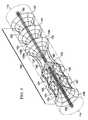
- FIG. 1is a schematic, perspective view of a reduced-pressure system for repairing a severed nerve including a nerve conduit and a first embodiment of a manifold and a scaffold having fiber guides with a section of the nerve conduit removed to show the manifold and scaffold;
- FIG. 2is a schematic, perspective view of a reduced-pressure system of for repairing a severed nerve including a nerve conduit and a second embodiment of a manifold and scaffold having fiber guides with a section of the nerve conduit removed to show the manifold;
- FIG. 3is a schematic, perspective view of the scaffold and fiber guides of the reduced-pressure systems shown in FIGS. 1 and 2 ;
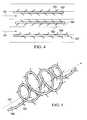
- FIG. 4is a schematic, side view of three embodiments of the fiber guides shown in FIG. 3 ;
- FIG. 5is a schematic, perspective view of a fourth embodiment of the fiber guides shown in FIG. 3 ;
- FIG. 6is a schematic, perspective view of the system in FIGS. 1 and 2 showing the nerve conduit enclosing the damaged nerve;
- FIG. 7is a schematic view of a fluid control system for the system shown in FIGS. 1 and 2 .
- a reduced pressure therapy system 100for applying reduced pressure at a tissue site in the body of a patient to repair a defect such as, for example, a damaged nerve.
- the damaged nervemay have been pinched, partially disconnected or severed, or partially degenerated as a result of disease.
- the damaged nerve in FIG. 1is a severed nerve 102 having a proximal segment 104 and a distal segment 106 relative to the central nervous system (CNS) of the patient.
- the severed nerve 102has been damaged at a nerve damage site 108 that has been severed or degenerated.
- the severed nerve 102may be branched or unbranched at the nerve damage site 108 .
- nerve damage siterefers to a wound or defect located on or within any nerve tissue, including, but not limited to, a disconnected or partially disconnected nerve, a degenerated or partially degenerated nerve, and a compressed or pinched nerve.
- reduced pressure tissue treatmentmay be used to enhance repair or regrowth of existing nerve tissue or to facilitate growth or grafted or transplanted nerve tissue and/or cells.
- the reduced pressure therapy system 100comprises a nerve conduit 110 that surrounds the severed nerve 102 at the nerve damage site 108 with a section of the nerve conduit 110 removed to show the nerve damage site 108 .
- the nerve conduit 110is substantially tubular in shape and closes the nerve damage site 108 and a portion of the proximal segment 104 and the distal segment 106 that has not been damaged.
- the nerve conduit 110has an inner surface 112 that forms a nerve gap 114 with the surface of the nerve damage site 108 , i.e., a luminal space between the inner surface 112 of the nerve conduit 110 and the surface of the nerve damage site 108 .
- the reduced pressure therapy system 100also comprises a reduced pressure source 115 for providing a reduced pressure and a manifold 120 fluidly coupled to the reduced pressure source 115 via a first conduit 125 .
- the manifold 120is generally tubular or cylindrical in shape (see, e.g., the manifold disclosed in copending U.S. patent application Ser. No. 12/648,463, incorporated herein by reference) and positioned within the nerve gap 114 .
- the manifold 120may have a variety of shapes depending on the type of nerve damage, and in this particular embodiment has a tubular shape to occupy a portion of the nerve gap 114 .
- the manifold 120may also contain scaffold structure 134 that provides structure for tissue growth and repair.
- the reduced pressure therapy system 100further comprises a canister 130 fluidly coupled between the reduced pressure source 115 and the manifold 120 via the first conduit 125 to collect bodily fluids such as blood or exudate that are drawn from the scaffold structure 134 and the nerve gap 114 .
- the reduced pressure source 115 and the canister 130are integrated into a single housing structure.
- FIG. 2A further embodiment of a reduced-pressure system 200 is shown in FIG. 2 and is substantially similar to the reduced-pressure system 100 .
- the reduced pressure therapy system 200comprises a nerve conduit 110 that surrounds the severed nerve 102 at the nerve damage site 108 with a section of the nerve conduit 110 removed to show the nerve damage site 108 .
- the nerve conduit 110is substantially tubular in shape and closes the nerve damage site 108 and a portion of the proximal segment 104 and the distal segment 106 that has not been damaged.
- the nerve conduit 110has an exterior surface 113 and an inner surface 112 that forms a nerve gap 114 with the surface of the nerve damage site 108 , i.e., a luminal space between the inner surface 112 of the nerve conduit 110 and the surface of the nerve damage site 108 .
- the reduced-pressure system 200also comprises a reduced pressure source 115 for providing a reduced pressure and a manifold 220 fluidly coupled to the pressure source 115 via a first conduit 125 .
- the manifold 220(see, e.g., the manifold disclosed in copending U.S. patent application Ser. No.
- a manifold chamber 221having a flange 222 extending from one end of the manifold chamber 221 for securing the manifold chamber 221 to the nerve conduit 110 .
- the other end of the manifold chamber 221is connected to the first conduit 125 so that the manifold 220 is held in fluid communication with the first conduit 125 .
- the manifold chamber 221may be constructed of any biocompatible material that is substantially impermeable to preserve the manifold's 220 fluid communication between the nerve gap 114 and the first conduit 125 .
- the manifold chamber 221is secured to the nerve conduit 110 by the flange 222 such that the manifold 220 is in fluid communication with the nerve gap 114 surrounding the surface of the nerve damage site 108 , but positioned outside of the nerve gap 114 .
- the flange 222is secured to the nerve conduit 110 with an adhesive.
- the flange 222is detachably secured to the nerve conduit 110 such that the flange 222 and manifold chamber 221 can be removed from the nerve conduit 110 after reduced pressure therapy is complete.
- the manifold 220extends through the wall of the nerve conduit 110 in direct fluid contact with the nerve gap 114 .
- the flange 222is secured to the exterior surface 113 of the nerve conduit 110 so that the manifold 220 is positioned adjacent to the exterior surface 113 to be in fluid communication with the nerve gap 114 via the porous wall of the nerve conduit 110 .
- Coupledincludes direct coupling or indirect coupling via a separate object.
- the term “coupled”also encompasses two or more components that are continuous with one another by virtue of each of the components formed from the same piece of material.
- the term “coupled”may include chemical, mechanical, thermal, or electrical coupling.
- Fluid couplingmeans that fluid is in communication with designated parts or locations.
- reduced pressuregenerally refers to a pressure that is less than the ambient pressure at a tissue site that is subjected to treatment. In most cases, this reduced pressure will be less than the atmospheric pressure of the location at which the patient is located.
- vacuumand “negative pressure” may be used to describe the pressure applied to the tissue site, the actual pressure applied to the tissue site may be significantly greater than the pressure normally associated with a complete vacuum. Consistent with this nomenclature, an increase in reduced pressure or vacuum pressure refers to a relative reduction of absolute pressure, while a decrease in reduced pressure or vacuum pressure refers to a relative increase of absolute pressure.
- ⁇ pmeans change in reduced pressure.
- a greater (i.e., more negative) ⁇ pmeans increased negative pressure (i.e., a greater change in pressure from ambient pressure).
- Reduced pressure treatmenttypically applies reduced pressure at ⁇ 5 mm Hg to ⁇ 500 mm Hg, more usually ⁇ 5 to ⁇ 300 mm Hg, including but not limited to ⁇ 50, ⁇ 125 or ⁇ 175 mm Hg.
- Reduced pressuremay be constant at a particular pressure level or may be varied over time. For example, reduced pressure may be applied and stopped periodically or ramped-up or -down over time.
- the systems 100 and 200further comprise a scaffold structure 134 including one or more scaffold guides positioned within the nerve gap 114 in fluid communication with the manifold 20 on one or both sides of the manifold 20 such as, for example, scaffold guide 135 .
- the scaffold guide 135has a generally frusto-tubular shape with a base opening 136 at the base end of the frustum and a vertex opening 137 at the other end of the frustum.
- the scaffold guide 135is positioned in the nerve gap 114 and oriented therein so that the vertex opening 137 is positioned closer to the manifold 20 than the base opening 136 which faces the proximal segment 104 when the vertex opening 137 is on the proximal side of the manifold 20 or faces the distal segment 106 when the vertex opening 137 is on the distal side of the manifold 20 .
- the scaffold structure 134 of the systems 100 , 200comprise six scaffold guides (only four shown in FIGS.
- scaffold guides 135 , 141 , 143 , 145 , 147 , and 149(collectively the “scaffold guides”) wherein the scaffold guides 135 , 141 , and 143 are positioned on the proximal side of the manifold 20 so that their vertex openings are closer to the manifold 20 than their base openings which face the proximal segment 104 .
- a system according to the inventionmay, however, comprise 1, 2, 3, 4, 5, 6, 7, 8 or more scaffold guides.
- the scaffold guides 145 , 147 , and 149are positioned on the distal side of the manifold 20 so that their vertex openings are closer to the manifold 20 than their base openings which face the distal segment 106 .
- the scaffold guidesmay be formed of a scaffold fabric material or a web-like material 139 as illustrated by the concentric rings 139 a and ribs 139 b . In either embodiment, the scaffold guides function as nodes within the nerve gap 114 for protein absorption and the initialization point for fibril formation.
- the structure of the scaffold guidesalso wicks and directs slow-moving fluid within the nerve gap 114 from the base opening 136 toward the vertex opening 137 and the source of the reduced pressure, i.e., the manifold 20 .
- the scaffold guidesmay be composed of any biocompatible material, but is preferably a bioabsorbable material.
- the scaffold structure 134may further comprise one or more fiber guides 160 extending through the vertex openings of each of the scaffold guides from the proximal segment 104 to the distal segment 106 of the severed nerve 102 .
- the fiber guides 160may form a fiber bundle 159 also extending between the proximal segment 104 and the distal segment 106 including, but not limited to, as many as one hundred fiber guides 160 .
- the fiber guides 160may also be fluidly and/or mechanically coupled to the proximal segment 104 and/or the distal segment 106 of the severed nerve 102 . Additionally, the fiber guide 160 may be fluidly and/or mechanically coupled to the manifold 20 .
- the scaffold guideswick and direct fluid toward the vertex openings of the scaffold guides and the fiber guides 160 which facilitate fibril formation between the scaffold guides and ultimately extending between the base openings of the scaffold guides.
- fibril formationcommences with direct fluid flow toward the vertex openings of the scaffold guides and along the fiber guides 160 as indicated by the fibers 151 that grow along the path created by the fiber guides 160 .
- the fibers 151may constitute either provisional matrix fibers such as but not limited to fibrin, collagens, proteoglycans, and laminin, or cellular based structures such as nerve fibers or supportive cell types.
- the provisional matrix and cellular based fibersmay be derived either from endogenous host sources, or from the introduction of exogenous fluids. As fibril formation increases the density of the fibers 151 , fibril formation expands outwardly between the base openings of the scaffold guides as indicated by fibers 153 . Ultimately, fibers 155 begin forming between the scaffold guides having vertex openings facing each other, e.g., scaffold guides 135 and 145 .
- the fiber guides 160act to guide cell migration and growth through the entire scaffold structure 134 and may be composed of any biocompatible material such as a bioabsorbable material. In certain cases, the fiber guides are composed of a biological material such as collagen or fibrin.
- fiber guides 162 , 164 , and 166comprise a strand of fiber material including protrusions for binding of proteins and cells from the slow-moving fluid within the nerve gap 114 to facilitate fibril formation. More specifically, fiber guides 162 and 164 include small barbs 163 and 165 extending from the strands of the fibril guides 162 and 164 in a direction with fluid flow and against fluid flow, respectively, depending upon the fluidics within the nerve gap 114 .
- the fiber guide 166includes protrusions in the shape of hooks 167 to facilitate protein binding and initiation sites of fibril formation through the nerve gap 114 without being aligned against fluid flow as are the small barbs 165 of the fiber guide 164 .
- the small barbs 163 and 165 and the hooks 167may also be oriented in a direction extending either toward the proximal segment 104 or the distal segment 106 of the severed nerve 102 as may be required by the fluidics within the nerve gap 114 .
- the fiber guides 162 , 164 , and 166 including the small barbs 163 and 165 and the hooks 167are composed of the same materials described for use in other scaffold materials such as, for example, collagen or fibrin.
- a fiber guide 160may comprise a strand of fiber material that has a form other than the linear form described above and shown in FIG. 4 .
- the strand of a fiber guide 168is shaped in the form of a spiral having a longitudinal axis substantially parallel to the flow of fluid through the nerve gap 114 as indicated by dashed arrow 161 .
- the fiber guide 168may also have protrusions extending from the strand such as, for example, barbs 169 which are similar to the small barbs 163 of the fiber guide 162 .
- the nerve conduit 110is shown in FIGS. 1 and 2 with a section removed to show the manifolds 120 , 220 and is shown as completely surrounding the nerve damage sites 108 as a closed nerve conduit 410 in FIG. 6 .
- the closed nerve conduit 410may be sealed by utilizing one or more stitches 415 or any other fastening device known in the art.
- the closed nerve conduit 410may be composed of a bioabsorbable or a bioinert material.
- Materials that may be used for nerve conduitsinclude, without limitation, polylactic acid (PLA), polyglycolic acid (PGA), polylactide-co-glycolide (PLGA), polyvinylpyrrolidone, polycaprolactone, polycarbonates, polyfumarates, caprolactones, polyamides, polysaccharides (including alginates (e.g., calcium alginate) and chitosan), hyaluronic acid, polyhydroxybutyrate, polyhydroxyvalerate, polydioxanone, polyorthoesthers, polyethylene glycols, poloxamers, polyphosphazenes, polyanhydrides, polyamino acids, polyacetals, polycyanoacrylates, polyurethanes, polyacrylates, ethylene-vinyl acetate polymers and other acyl substituted cellulose acetates and derivatives thereof, polystyrenes, polyvinyl chloride, polyvinyl fluoride, poly(vinylimi
- a nerve conduit 110 , 410may be an unbroken substantially tubular structure fitted across a gap between a proximal and distal nerve stump such as depicted in FIG. 6 .
- substantially tubular nerve conduitsalso referred to as nerve guides, include without limitation NEURAGEN® and NEUROFLEXTM collagen conduits.
- a nerve conduitmay also be formed from a wrap that is positioned around a disconnected or damaged (e.g., pinched) nerve and sealed with a closure, such as a suture.
- wrap-type nerve conduitsinclude, without limitation, NEUROMENDTM and NEURAWRAPTM collagen conduits.
- the nerve conduitis made of a material that encloses the damaged nerve, so as to exclude infiltration of non-nerve cells such as glia.
- the nerve conduit materialis permeable, thereby allowing fluid and protein factors to diffuse through the conduit.
- the pores in a nerve conduitmay be sufficiently small so as to exclude the entry of cells into the conduit lumen (e.g., pores having an interior diameter or average interior diameter of between about 5 ⁇ m and 50 ⁇ m, 10 ⁇ m and 30 ⁇ m or 10 ⁇ m and 20 ⁇ m).
- the conduitscomprise an internal diameter of less than about 6.0 mm, such as about 5, 4, 3, 2.5 or 2 mm.
- the reduced-pressure systems 100 , 200 , 700may further comprise a pressure sensor 740 operably connected to the first conduit 125 to measure the reduced pressure being applied to the manifolds 120 , 220 .
- the systems 100 , 200 , 700may further include a control unit 745 electrically connected to the pressure sensor 740 and the reduced pressure source 115 .
- the pressure sensor 740measures the reduced pressure within the nerve gap 114 and also may indicate whether the first conduit 125 is occluded with blood or other bodily fluids.
- the pressure sensor 740also provides feedback to control unit 745 which regulates the reduced pressure therapy being applied by the reduced pressure source 115 through the first conduit 125 to the manifolds 120 , 220 .
- the reduced-pressure systems 100 , 200 , 700may also comprise a fluid supply 750 fluidly coupled to the first conduit 125 via a second conduit 752 and operatively connected to the control unit 745 .
- the fluid supply 750may be used to deliver growth and/or healing agents to the nerve damage site 108 including, without limitation, an antibacterial agent, an antiviral agent, a cell-growth promotion agent, an irrigation fluid, antibodies or other chemically active agents.
- the systems 100 , 200 , 700further comprises a first valve 754 positioned in the second conduit 752 to control the flow of fluid therethrough, and a second valve 756 positioned in the first conduit 125 between the reduced pressure source 115 and the juncture between the first conduit 125 and the second conduit 752 to control the flow of reduced pressure.
- the control unit 745is operatively connected to the first and second valves 754 , 756 to control the delivery of reduced pressure and/or fluid from the fluid supply 750 , respectively, to the manifolds 120 , 220 as required by the particular therapy being administered to the patient.
- the fluid supply 150may deliver the liquids as indicated above, but may also deliver air to the manifolds 120 , 220 to promote healing and facilitate drainage at the site of the nerve damage site 108 .
- manifoldrefers to a substance or structure that is provided to assist in directing reduced pressure to, delivering fluids to, or removing fluids from a tissue site.
- a manifoldcan include a plurality of flow channels or pathways that are interconnected to improve distribution of fluids provided to and removed from the area of tissue around the manifold.
- manifoldsmay include, without limitation, devices that have structural elements arranged to form flow channels, cellular foams such as open-cell foam, porous tissue collections, and liquids, gels and foams that include or cure to include flow channels.
- scaffoldrefers to a substance or structure applied to or in a wound or defect that provides a structural matrix for the growth of cells and/or the formation of tissue.
- a scaffoldis often a three dimensional porous structure.
- the scaffoldcan be infused with, coated with, or comprised of cells, growth factors, extracellular matrix components, nutrients, integrins, or other substances to promote cell growth.
- a scaffoldcan take on characteristics of a manifold by directing flow through the matrix.
- a manifoldcan transmit flow to the scaffold and tissue; in the context of reduced pressure treatment, the manifold can be in fluid communication with the scaffold.
- the invention disclosed herediscloses methods and apparatuses for controlling cellular-level based patterns of fluid flow that would allow for control of patterned protein organization at a microscopic, nanoscopic, or mesoscopic scale amenable to provide a structured manifold and, optionally, a scaffold material for cellular migration, differentiation, and like behavior necessary for functional regeneration of tissues.
- the methods, scaffolds, manifolds, flow sources and systems disclosed hereinprovide an active mechanism by which to promote the endogenous deposition of proteins and organization of the provisional matrix with biochemical and physical cues to direct cellular colonization of a scaffold or tissue space.
- the present inventionthus enhances current technology by exploiting the active force of directed fluid flow, providing a framework upon which to design manifolds and scaffolds based upon the need of the biology under the influence of fluid flow.
- Flow vectors and pathwaysare utilized to enhance protein deposition and cellular colonization.
- the systems provided hereinare designed to promote establishment of a provisional matrix network with a seamless transition from the healthy tissue edges through a scaffold or tissue site to promote a functional tissue continuum.
- the apparatuses, methods and systems disclosed hereinprovide a means for active guidance of tissue regeneration through an implanted scaffold or within a tissue site to promote functional recovery.
- This active guidanceoccurs through mechanisms of controlled fluid flow, which can be used to initiate or augment the early stages of the body's own natural healing process; a manifold can provide the active guidance necessary to create a controlled fluid flow.
- the controlled flow vectors that the manifolds providecan be used to facilitate the directed influx of cells and proteins into a scaffold. Creation of specific flow pathways within a tissue site or scaffold can lead to patterned deposition of proteins, such as collagen and fibrin within the manifold, scaffold or tissue space.
- Biochemical cues from cytokines, growth factors, and cells bound within the provisional matrixcan work in conjunction with the natural physical cues of the provisional matrix and extracellular matrix to guide the subsequent migration of endogenous cells during the repair stages of healing. These cues act to establish a biological continuum that emanates from the healthy tissues and passes through the scaffolding or tissue space to facilitate a continuous guidance pathway for organized tissue regeneration.
- the inventionconcerns a new approach to wound healing, flow (or gradient) activated tissue engineering.
- this approachinvolves a source or generator of flow that forms a gradient for controlled movement of either endogenous or exogenous fluids into, out of, or through a tissue space for the organized deposition of proteins and/or spatial concentration of cytokines and growth factors, with subsequent formation of a directionally oriented provisional matrix.
- the tissue spacebeing defined here includes, but is not limited to, the region surrounding a site of nerve tissue damage.
- Fluid flow into, through, or out of the nerve tissue spacecan be refined and directed through the inclusion of additional elements to the system including manifolds and/or scaffolds.
- the coordinated elements of the systemare designed to create flow parameters, pathways, and patterns sufficiently detailed in scale as to be able to influence and direct the controlled adsorption of proteins, the organization of matrix, and organized colonization of specific cell types. Individual elements of the system are as follows.
- Source or Generator of Flowis induced into, through, or out of the nerve tissue space by methods or apparatuses that introduce changes in mechanical, chemical, and/or electrical potentials. These generators of flow provide either a gradient or a change in potential from the site or reservoir of endogenous or exogenous fluids to the placement position of the flow generator or its extension element (i.e., manifold or scaffold).
- the source of flowcomprises a source of reduced pressure.
- Systems and apparatuses according to the inventionmay also comprise valves or arrays of valves that control the application and amount of negative pressure applied to the manifold.
- nerve conduits and/or manifolds described hereincomprise a pressure sensor.
- the amount of negative pressure applied by a sourceis regulated based on the amount of negative pressure that is sensed in the manifold or nerve conduit or at the site of tissue damage.
- ManifoldThe flow generators are the driving force for stimulating the flow of fluids.
- Manifoldsare apparatuses for refining the pattern of flow between the source or generator of flow and the tissue space.
- the macroscale level of flowis refined by specialized manifolds utilized for directed localization to a single point or to a plurality of selectively positioned points for creating initiation sites for microscale flow pathways within the manifold/scaffold and, ultimately, the tissue space.
- the manifoldmay also serve as a conduit for the removal of fluids from and as an apparatus for the delivery of exogenous fluids to the tissue space.
- a manifoldgenerally refers to a physical substance or structure that serves to assist in applying and translating a mechanical, chemical, electrical or similar alterations into changes in the flow of a fluid, herein defined as the movement of liquids, gases, and other deformable substances such as proteins, cells, and other like moieties.
- this physical deviceincludes a single point or plurality of points for the egress or evacuation of pressure, fluids, and like substances capable of translating the movement of fluids in a scaffold, as defined above. This can include, but is not limited to, the introduction of exogenous factors such as cells and/or therapeutic moieties into the scaffold through the lumen or plurality of lumens present in the manifold.
- a manifoldincludes a single point or plurality of points for the ingress or introduction of fluid from the scaffold back toward the point source of flow.
- Flow distributed by the manifoldcan direct the movement of endogenous proteins, growth factors, cytokines, and cells from their resident locations within the host to the tissue space or scaffold in an organized manner.
- the establishment of flow along these pathwaysleads to the deposition of proteins and provisional matrix that creates an interfacial endogenous network connecting the host to the scaffold. Extensions of this matrix can be established within the scaffold through selective positioning of the manifold flow initiation sites with flow promoting scaffolding designs.
- the organized protein deposition and provisional matrixprovide a biochemical and physical framework that stimulates the attachment and migration of cells along directed pathways throughout the scaffold and the tissue space.
- the resulting endogenous network of proteins, growth factors, and cellsprovides a foundation upon which subsequent phases of the body's own tissue repair and regeneration mechanisms can build.
- Flow generating sourcesinclude, but are not limited to generators of negative pressure; generators of positive pressure; and generators of osmotic flow.
- the flow gradient established in the manifoldmay be further refined through the scaffold, to deliver a flow gradient to the scaffold to optimize flow through the scaffold as needed for the particular defect.
- Many of the embodiments disclosed hereinare manifolds capable of translating changes in pressure and the like into controlled movement of fluids, optionally through a physical scaffold, for the purposes of directed tissue regeneration. These embodiments are generally specified for a particular application in the regeneration of specific tissues, but are not limited to a particular tissue therein.
- alterations in the aforementioned mechanical, chemical, or electrical impetusmust be translated from the singular gradient source toward a physical substrate or scaffold to elicit cellular-level changes in protein adsorption, matrix organization, cell migration, and other tissue regeneration-related behaviors.
- These alterationsare multivariate in nature and can include mechanical changes that elicit a physical change in pressure applied to the scaffold as applied to the site of the wound or desired site of tissue regeneration, chemical changes that elicit a gradient in protein and/or ion concentrations, which result in the creation of osmotic gradients capable of inducing flow, or electrical changes that create a gradient of current/ion exchange allowing for propagation of electrical signals from the point source.
- the manifoldcomprises a physical structure in close apposition to or within the contents of a scaffold and serves to propagate an alteration in a physical parameter, whether it be mechanical, chemical, electrical, or something similar in nature, for the means of directing these changes from its point source to the scaffolding material.
- the placement of this manifold with respect to its location with regard to that of the scaffoldmay be of crucial importance for facilitating controlled and directed regeneration of specific tissue types. For example, in peripheral nerve where regeneration primarily occurs in a unidirectional manner from the proximal to distal nerve stumps, it may be important to place the manifold along the length of a nerve conduit more toward it distal end to help direct regeneration toward that end. However, it may also be important to not place the manifold at the most distal aspect of the scaffold/conduit as soluble factors derived from the distal stump have been shown to be important for directing nerve regeneration toward its source.
- Manifoldsmay be composed of a bioabsorbable or bioinert material. Examples include non-bioabsorbable materials such as medical grade silicone polymers, metals, polyvinylchloride (PVC), and polyurethane. Bioabsorbable polymers such as collagen, polylactic acid (PLA), polyglycolic acid (PGA), polylactide-co-glycolide (PLGA), a polysaccharide, a hydroxyapatite, or a polyethylene glycol, or combinations thereof, can also be used. Some manifolds are also a mix of non-bioresorbable and bioresorbable materials. In general material used for a scaffold may also be used to compose a manifold and such materials are further detailed below. In certain aspects, manifold materials are structured to include a high void fraction for improved bioabsorption properties.
- PVCpolyvinylchloride
- Bioabsorbable polymerssuch as collagen, polylactic acid (PLA), polyglycolic acid (PGA), polyl
- Manifold support structuressuch as a manifold chamber and/or flange may be composed of any acceptable biocompatible material.
- a support structurewill typically be impermeable and surround the manifold so as to maintain manifold pressure.
- a scaffold for use according to the inventionis coupled to a manifold, provides physical guidance to direct the pathway of fluid flow in the tissue site, creating avenues for the movement and migration of adhesive proteins and cells, respectively, which are integral to the establishment of a provisional matrix in predetermined patterns of organization within the tissue space.
- the methods and apparatuses described for fluid flow-induced and gradient-induced generation of tissueshave direct implications into the design of the scaffolds.
- scaffoldsserve to refine the pathways of fluid flow within the tissue space to cellular level patterns from the fluid source to the point(s) of flow initiation within the manifold.
- a scaffoldmay embody characteristics of a manifold or be combined in conjunction with a manifold for refinement of the flow pathways within the tissue site.
- a scaffoldis a reticulated structure comprising high void fraction for improved bioabsorption properties.
- Scaffoldsmay also comprise retention structures as described herein such as funnel guides and fiber guides.
- funnel guidesmay be used to direct the diffusion and/or migration of cells or growth factors at a site of nerve damage.
- multiple funnel guidessuch as 2, 3, 4, 5, 6, 7, 8 or more funnel guides are comprised in a scaffold.
- a funnel guidemay be composed of a hydrophobic material and may be bioabsorbable so as to degrade as nerve tissue grows into the site of the nerve damage.
- Funnel guidesmay also be hydrophilic to assist in the directed movement of slow moving fluids e.g., by wicking.
- Funnel guidesmay also have bioabsorption properties that differ from the narrow to the wide end of the funnel guide.
- the narrow end of the funnel guidemay be absorbed at a faster rate so that the aperture of the narrow end becomes wider as tissue regrowth occurs.
- funnel guides closer to the proximal end of the nerve damage sitemay be composed of a material that is absorbed at a faster rate so that funnel structures closer to the proximal end of a nerve damage site are absorbed more rapidly.
- Fiber guides in scaffoldsmay also be composed of bioabsorbable material such that the guides are absorbed as tissue growth or regrowth occurs.
- fiber guidesmay comprise protrusions (e.g., barbs) or hook structures and may be essentially linear or form a spiral as they extend through the scaffold at the nerve damage site.
- the fiber guides and associated structurese.g., fiber protrusions and hooks
- the fiber structurescomprise bioactive molecules as part of their structure.
- fiber structuresmay comprise growth factors that enhance cell growth along the length of the fibers or binding moieties (such as antibodies) that bind cells or growth factors to the fibers to enhance the growth or regrowth of nerve tissue.
- Nonlimiting examples of suitable scaffold, funnel and fiber materialsinclude extracellular matrix proteins such as fibrin, collagen or fibronectin, and synthetic or naturally occurring polymers, including bioabsorbable or non-bioabsorbable polymers, such as polylactic acid (PLA), polyglycolic acid (PGA), polylactide-co-glycolide (PLGA), polyvinylpyrrolidone, polycaprolactone, polycarbonates, polyfumarates, caprolactones, polyamides, polysaccharides (including alginates (e.g., calcium alginate) and chitosan), hyaluronic acid, polyhydroxybutyrate, polyhydroxyvalerate, polydioxanone, polyethylene glycols, poloxamers, polyphosphazenes, polyanhydrides, polyamino acids, polyortho esters, polyacetals, polycyanoacrylates, polyurethanes, polyacrylates, ethylene-vinyl acetate polymers and other acyl substitute
- the scaffoldcan also comprise ceramics such as hydroxyapatite, coralline apatite, calcium phosphate, calcium sulfate, calcium carbonate or other carbonates, bioglass, allografts, autografts, xenografts, decellularized tissues, or composites of any of the above.
- the scaffoldcomprises collagen, polylactic acid (PLA), polyglycolic acid (PGA), polylactide-co-glycolide (PLGA), a polyurethane, a polysaccharide, an hydroxyapatite, or a polytherylene glycol.
- the scaffoldcan comprise combinations of any two, three or more materials, either in separate areas of the scaffold, or combined noncovalently, or covalently (e.g., copolymers such as a polyethylene oxide-polypropylene glycol block copolymers, or terpolymers), or combinations thereof.
- Suitable matrix materialsare discussed in, for example, Ma and Elisseeff, 2005, and Saltzman, 2004.
- bioactive agentsmay, in some cases, be incorporated directly onto a manifold or scaffold material (i.e., to generate a bioactive manifold and/or scaffold).
- a manifold or scaffold materiali.e., to generate a bioactive manifold and/or scaffold.
- agents that facilitate tissue growthsuch as collagen or fibrin may be directly incorporated onto or into a manifold or scaffold material.
- immune regulator agentssuch as rapamycin may be incorporated into manifold or scaffold structures.
- soluble bioactive agentsmay be introduced at a site of tissue damage by virtue of flow through the tissue site.
- a manifoldmay be in fluid communication with a fluid source and a bioactive agent may be introduced into the fluid source and thereby into the manifold and damaged nerve tissue.
- Nonlimiting examples of useful bioactive growth factors for various applicationsare growth hormone (GH), a bone morphogenetic protein (BMP), transforming growth factor- ⁇ (TGF- ⁇ ), a TGF- ⁇ , a fibroblast growth factor (FGF), granulocyte-colony stimulating factor (G-CSF), granulocyte/macrophage-colony stimulating factor (GM-CSF), epidermal growth factor (EGF), platelet derived growth factor (PDGF), insulin-like growth factor (IGF), vascular endothelial growth factor (VEGF), hepatocyte growth factor/scatter factor (HGF/SF), an interleukin, tumor necrosis factor- ⁇ (TNF- ⁇ ) or nerve growth factor (NGF).
- GHgrowth hormone
- BMPbone morphogenetic protein
- TGF- ⁇transforming growth factor- ⁇
- TGF- ⁇TGF- ⁇
- FGFfibroblast growth factor
- G-CSFgranulocyte-colony stimulating factor
- GM-CSF
- Nerve Tissue Repair and EngineeringThe apparatuses and systems disclosed herein can be used for nerve tissue repair and engineering in various contexts including the following.
- a generator of flowmay be combined with manifolds and/or scaffolds to direct the regeneration of lost tissue at a site of injury or compromised function.
- Tissues lost from traumatic injury, surgery, burns, or other causese.g., infection or autoimmune disease
- Functional nerve tissueis directed to regenerate.
- a generator of flowmay be combined with manifolds and/or scaffolds to retard disease progression of an affected nerve tissue such as occurs, e.g., in autoimmune disease.
- a generator of flowmay be combined with manifolds and/or scaffolds to maintain the viability of explanted tissues either for in vitro study, ex vivo scaffold or implant preparation, or in vivo transplant.
- a generator of flow combined with a manifoldmay be used to provide fluid flow to the tissue and to control waste removal from the tissue.
- a generator of flowmay be combined with manifolds and/or scaffolds to promote the expansion of existing tissues.
- the methods, scaffolds, manifolds, flow sources and systems of the inventioncan be used to direct the growth of tissues where additional tissue quantity is needed or desired
- a generator of flowmay be combined with manifolds and/or scaffolds to accelerate the rate of tissue formation within a natural healing response.
- the methods, scaffolds, manifolds, flow sources and systems of the inventionmay be used to accelerate tissue growth by augmenting formation of provisional matrices, facilitating its stable positioning, and aiding in recruitment of cells to the tissue space.
- a generator of flowmay be combined with manifolds and/or scaffolds to stimulate differentiation of stem cells or other pluripotent cells into specific lineages.
- Application of flow using the methods, scaffolds, manifolds, flow sources and systems of the inventionmay be used to direct pluripotent cells into specific cell lineages needed to foster growth in the tissue space.
- a generator of flowmay be combined with manifolds and/or scaffolds to introduce exogenous growth factors, proteins, cells, or pharmaceutical agents into the tissue space to augment tissue repair, regeneration, and/or maintenance.
- a generator of flowmay be combined with manifolds and/or scaffolds to facilitate formation of matrices in vitro that may subsequently be used for in vivo transplantation.
- a generator of flowmay be combined with manifolds and/or scaffolds to promote integration of transplanted tissue into the host environment. This can be applied to autograft, allograft, or xenograft transplants.
- a flow generatormay be combined with manifolds and/or scaffolds to guide the directed deposition and orientation of ECM expressed by cells and tissues.
- the directed orientation of ECMhas an impact in organizing and directing the attachment and colonization of subsequent cell layers and tissues.
Landscapes
- Health & Medical Sciences (AREA)
- Life Sciences & Earth Sciences (AREA)
- Heart & Thoracic Surgery (AREA)
- Veterinary Medicine (AREA)
- Public Health (AREA)
- General Health & Medical Sciences (AREA)
- Animal Behavior & Ethology (AREA)
- Engineering & Computer Science (AREA)
- Biomedical Technology (AREA)
- Vascular Medicine (AREA)
- Surgery (AREA)
- Hematology (AREA)
- Anesthesiology (AREA)
- Chemical & Material Sciences (AREA)
- Nuclear Medicine, Radiotherapy & Molecular Imaging (AREA)
- Medicinal Chemistry (AREA)
- Medical Informatics (AREA)
- Molecular Biology (AREA)
- Neurology (AREA)
- Dermatology (AREA)
- Transplantation (AREA)
- Organic Chemistry (AREA)
- General Chemical & Material Sciences (AREA)
- Chemical Kinetics & Catalysis (AREA)
- Pharmacology & Pharmacy (AREA)
- Bioinformatics & Cheminformatics (AREA)
- Epidemiology (AREA)
- Oral & Maxillofacial Surgery (AREA)
- Neurosurgery (AREA)
- Dispersion Chemistry (AREA)
- Biophysics (AREA)
- Otolaryngology (AREA)
- Materials For Medical Uses (AREA)
- Prostheses (AREA)
- Media Introduction/Drainage Providing Device (AREA)
- External Artificial Organs (AREA)
- Treatment Of Fiber Materials (AREA)
Abstract
Description
- U.S. Pat. No. 4,787,906
- U.S. Pat. No. 6,103,255
- U.S. Pat. No. 6,135,116
- U.S. Pat. No. 6,365,146
- U.S. Pat. No. 6,695,823
- U.S. Pat. No. 6,696,575
- U.S. Pat. No. 6,767,334
- U.S. Pat. No. 6,814,079
- U.S. Pat. No. 6,856,821
- U.S. Pat. No. 6,936,037
- U.S. Pat. No. 6,951,553
- U.S. Pat. No. 6,994,702
- U.S. Pat. No. 7,004,915
- U.S. Pat. No. 7,070,584
- U.S. Pat. No. 7,077,832
- U.S. Pat. No. 7,108,683
- U.S. Pat. No. 7,160,553
- U.S. Pat. No. 7,186,244
- U.S. Pat. No. 7,214,202
- U.S. Pat. No. 7,279,612
- U.S. Pat. No. 7,316,672
- U.S. Pat. No. 7,346,945
- U.S. Pat. No. 7,351,250
- U.S. Pat. No. 7,384,786
- U.S. Patent Publn. 2003/0225347
- U.S. Patent Publn. 2005/0260189
- U.S. Patent Publn. 2007/0123895
- U.S. Patent Publn. 2008/0033324
- U.S. Patent Publn. 2008/0208358
- U.S. Provisional Patent Appln. 61/142,053
- U.S. Provisional Patent Appln. 61/142,065
- Anderson et al.,Tissue Eng.,13:2525-38, 2007.
- Brody et al.,J. Biomed. Mater. Res. B: Appl. Biomater.,83:16-43, 2007.
- Gemmiti et al.,Tissue Eng.,12:469-79, 2006.
- Lago et al.,IEEE Trans. Biomed. Eng.,54:1129-37, 2007.
- Ma et al.,Scaffolding in Tissue Engineering,2005.
- Manwaring et al.,Biomaterials,22:3155-3168, 2001.
- Manwaring et al.,Biomaterials,25:3631-3638, 2004.
- Mercier et al.,Biomaterials,26:1945-1952, 2005.
- Mikos et al.,J. Biomed. Mater. Ref,27:183-189, 2004.
- Norman et al.,Ann Biomed Eng.,34:89-101, 2006.
- PCT Appln. WO 00/38755A2
- PCT Appln. WO 00/61206A1
- PCT Appln. WO 03/018098A2
- PCT Appln. WO 03/092620A2
- PCT Appln. WO 04/060148A2
- PCT Appln. WO 04/105576A2
- PCT Appln. WO 05/009488A2
- PCT Appln. WO 05/033273A2
- PCT Appln. WO 06/004951
- PCT Appln. WO 06/127853
- PCT Appln. WO 07/067,685A2
- PCT Appln. WO 07/092,397A2
- PCT Appln. WO 07/106,589A2
- PCT Appln. WO 07/106,590A2
- PCT Appln. WO 07/106,591A2
- PCT Appln. WO 07/106,592A2
- PCT Appln. WO 07/106,594A2
- PCT Appln. WO 07/133,555A2
- PCT Appln. WO 07/133,556A2
- PCT Appln. WO 07/143,060A2
- PCT Appln. WO 07/196,590
- PCT Appln. WO 08/013,896A2
- PCT Appln. WO 08/036,162A2
- PCT Appln. WO 08/036,359A2
- PCT Appln. WO 08/036,361A2
- PCT Appln. WO 08/042,481A2
- PCT Appln. WO 08/091,521A2
- Pfister et al.,Neurosurgery,60:137-41, 2007.
- Saltzman,Tissue Engineering: Engineering Principles for the Design of Replacement Organs and Tissues,2004.
- Sachlos et al.,Cells and Mat.,5:29-40, 2003.
- Segvich et al.,J. Biomed. Mater. Res. B: Appl. Biomater.,84B:340-349, 2008.
- Shimko et al.,J Biomed Mater. Res. B: Appl. Biomater.,73:315-24, 2005.
- Takahashi et al.,Cell,126:663-76, 2006.
- Tan et al.,Bone,41:745-751, 2007.
- Tan et al.,Biochem. Biophys. Res. Comm.,369:1150-1154, 2008.
- Walsh et al.,Tissue Eng.,11:1085-1094, 2005.
- Wen et al.,Handbook of Nanostructured Biomaterials and Their Applications in Nanobiotechnology,1-23, 2005.
Claims (51)
Priority Applications (1)
| Application Number | Priority Date | Filing Date | Title |
|---|---|---|---|
| US14/252,664US8998934B2 (en) | 2008-12-31 | 2014-04-14 | System for providing fluid flow to nerve tissues |
Applications Claiming Priority (6)
| Application Number | Priority Date | Filing Date | Title |
|---|---|---|---|
| US14205308P | 2008-12-31 | 2008-12-31 | |
| US14206508P | 2008-12-31 | 2008-12-31 | |
| US23469209P | 2009-08-18 | 2009-08-18 | |
| US23877009P | 2009-09-01 | 2009-09-01 | |
| US12/648,642US8734474B2 (en) | 2008-12-31 | 2009-12-29 | System for providing fluid flow to nerve tissues |
| US14/252,664US8998934B2 (en) | 2008-12-31 | 2014-04-14 | System for providing fluid flow to nerve tissues |
Related Parent Applications (1)
| Application Number | Title | Priority Date | Filing Date |
|---|---|---|---|
| US12/648,642DivisionUS8734474B2 (en) | 2008-12-31 | 2009-12-29 | System for providing fluid flow to nerve tissues |
Publications (2)
| Publication Number | Publication Date |
|---|---|
| US20140277001A1 US20140277001A1 (en) | 2014-09-18 |
| US8998934B2true US8998934B2 (en) | 2015-04-07 |
Family
ID=42285800
Family Applications (11)
| Application Number | Title | Priority Date | Filing Date |
|---|---|---|---|
| US12/648,458Active2030-11-17US8257372B2 (en) | 2008-12-31 | 2009-12-29 | System for providing fluid flow to nerve tissues |
| US12/648,475Expired - Fee RelatedUS9125766B2 (en) | 2008-12-31 | 2009-12-29 | Tissue roll scaffolds |
| US12/648,642Active2031-11-29US8734474B2 (en) | 2008-12-31 | 2009-12-29 | System for providing fluid flow to nerve tissues |
| US12/648,463Active2033-03-19US9351882B2 (en) | 2008-12-31 | 2009-12-29 | System for providing fluid flow to nerve tissues |
| US13/554,724Expired - Fee RelatedUS8449562B2 (en) | 2008-12-31 | 2012-07-20 | System for providing fluid flow to nerve tissues |
| US13/870,059Active2030-01-11US8992552B2 (en) | 2008-12-31 | 2013-04-25 | System for providing fluid flow to nerve tissues |
| US14/252,664ActiveUS8998934B2 (en) | 2008-12-31 | 2014-04-14 | System for providing fluid flow to nerve tissues |
| US14/811,355Active2031-06-11US10155074B2 (en) | 2008-12-31 | 2015-07-28 | Tissue roll scaffolds |
| US15/134,161Active2030-08-29US10493186B2 (en) | 2008-12-31 | 2016-04-20 | System for providing fluid flow to nerve tissues |
| US16/186,097AbandonedUS20190091387A1 (en) | 2008-12-31 | 2018-11-09 | Tissue Roll Scaffolds |
| US16/671,460Active2030-10-04US11357904B2 (en) | 2008-12-31 | 2019-11-01 | System for providing fluid flow to nerve tissues |
Family Applications Before (6)
| Application Number | Title | Priority Date | Filing Date |
|---|---|---|---|
| US12/648,458Active2030-11-17US8257372B2 (en) | 2008-12-31 | 2009-12-29 | System for providing fluid flow to nerve tissues |
| US12/648,475Expired - Fee RelatedUS9125766B2 (en) | 2008-12-31 | 2009-12-29 | Tissue roll scaffolds |
| US12/648,642Active2031-11-29US8734474B2 (en) | 2008-12-31 | 2009-12-29 | System for providing fluid flow to nerve tissues |
| US12/648,463Active2033-03-19US9351882B2 (en) | 2008-12-31 | 2009-12-29 | System for providing fluid flow to nerve tissues |
| US13/554,724Expired - Fee RelatedUS8449562B2 (en) | 2008-12-31 | 2012-07-20 | System for providing fluid flow to nerve tissues |
| US13/870,059Active2030-01-11US8992552B2 (en) | 2008-12-31 | 2013-04-25 | System for providing fluid flow to nerve tissues |
Family Applications After (4)
| Application Number | Title | Priority Date | Filing Date |
|---|---|---|---|
| US14/811,355Active2031-06-11US10155074B2 (en) | 2008-12-31 | 2015-07-28 | Tissue roll scaffolds |
| US15/134,161Active2030-08-29US10493186B2 (en) | 2008-12-31 | 2016-04-20 | System for providing fluid flow to nerve tissues |
| US16/186,097AbandonedUS20190091387A1 (en) | 2008-12-31 | 2018-11-09 | Tissue Roll Scaffolds |
| US16/671,460Active2030-10-04US11357904B2 (en) | 2008-12-31 | 2019-11-01 | System for providing fluid flow to nerve tissues |
Country Status (12)
| Country | Link |
|---|---|
| US (11) | US8257372B2 (en) |
| EP (5) | EP2370118B1 (en) |
| JP (4) | JP5611980B2 (en) |
| KR (4) | KR20110102924A (en) |
| CN (4) | CN102264407B (en) |
| AU (4) | AU2009335114A1 (en) |
| CA (4) | CA2745462C (en) |
| MX (4) | MX2011007079A (en) |
| RU (4) | RU2011122956A (en) |
| SG (4) | SG172013A1 (en) |
| TW (4) | TW201029686A (en) |
| WO (4) | WO2010078345A2 (en) |
Families Citing this family (125)
| Publication number | Priority date | Publication date | Assignee | Title |
|---|---|---|---|---|
| JP4673305B2 (en)* | 2003-08-11 | 2011-04-20 | ウィルソン−クック・メディカル・インコーポレーテッド | Surgical graft |
| US9820888B2 (en) | 2006-09-26 | 2017-11-21 | Smith & Nephew, Inc. | Wound dressing |
| EP2148634A1 (en)* | 2007-05-15 | 2010-02-03 | Axongen Ab | Fibrin-based nerve repair conduit and method of producing the same |
| GB0804654D0 (en)* | 2008-03-13 | 2008-04-16 | Smith & Nephew | Vacuum closure device |
| CA2745462C (en)* | 2008-12-31 | 2014-07-15 | Kci Licensing, Inc. | Tissue roll scaffolds |
| GB0902368D0 (en) | 2009-02-13 | 2009-04-01 | Smith & Nephew | Wound packing |
| DE102009057962B4 (en)* | 2009-12-11 | 2012-09-20 | Karlsruher Institut für Technologie | Nerve prosthesis and method for making a nerve prosthesis |
| JP6013921B2 (en)* | 2010-02-23 | 2016-10-25 | エル−ヴイエイディー テクノロジー インコーポレイティッドL−Vad Technology,Inc. | Vacuum-assisted transcutaneous device |
| US8623047B2 (en)* | 2010-04-30 | 2014-01-07 | Kci Licensing, Inc. | System and method for sealing an incisional wound |
| KR101679426B1 (en)* | 2010-04-30 | 2016-11-25 | 에스케이이노베이션 주식회사 | A method of preparing high graded lube base oil using unconverted oil |
| US8758374B2 (en) | 2010-09-15 | 2014-06-24 | University Of Utah Research Foundation | Method for connecting nerves via a side-to-side epineurial window using artificial conduits |
| US20160346444A1 (en)* | 2010-09-24 | 2016-12-01 | Kci Licensing, Inc. | Cellular control and tissue regeneration systems and methods |
| US9408956B2 (en)* | 2010-09-24 | 2016-08-09 | Kci Licensing, Inc. | Cellular control and tissue regeneration systems and methods |
| US11214610B2 (en) | 2010-12-01 | 2022-01-04 | H. Lundbeck A/S | High-purity production of multi-subunit proteins such as antibodies in transformed microbes such as Pichia pastoris |
| US9884909B2 (en) | 2010-12-01 | 2018-02-06 | Alderbio Holdings Llc | Anti-NGF compositions and use thereof |
| EP2646468B1 (en) | 2010-12-01 | 2018-07-25 | AlderBio Holdings LLC | Anti-ngf compositions and use thereof |
| US9078878B2 (en) | 2010-12-01 | 2015-07-14 | Alderbio Holdings Llc | Anti-NGF antibodies that selectively inhibit the association of NGF with TrkA, without affecting the association of NGF with p75 |
| US9067988B2 (en) | 2010-12-01 | 2015-06-30 | Alderbio Holdings Llc | Methods of preventing or treating pain using anti-NGF antibodies |
| US9539324B2 (en) | 2010-12-01 | 2017-01-10 | Alderbio Holdings, Llc | Methods of preventing inflammation and treating pain using anti-NGF compositions |
| AU2012212070A1 (en) | 2011-02-04 | 2013-09-19 | University Of Massachusetts | Negative pressure wound closure device |
| US9421132B2 (en) | 2011-02-04 | 2016-08-23 | University Of Massachusetts | Negative pressure wound closure device |
| US9302034B2 (en) | 2011-04-04 | 2016-04-05 | Smith & Nephew, Inc. | Negative pressure wound therapy dressing |
| MX364446B (en) | 2011-04-15 | 2019-04-26 | Univ Massachusetts | Surgical cavity drainage and closure system. |
| EP3851131A1 (en) | 2011-05-31 | 2021-07-21 | LifeCell Corporation | Adipose tissue matrices |
| WO2013066619A1 (en)* | 2011-10-17 | 2013-05-10 | University Of Utah Research Foundation | Methods and devices for connecting nerves |
| US10842494B2 (en) | 2011-10-17 | 2020-11-24 | University Of Utah Research Foundation | Methods and devices for connecting nerves |
| JP6202686B2 (en)* | 2011-11-18 | 2017-09-27 | ケーシーアイ ライセンシング インコーポレイテッド | Tissue treatment system and method having a porous substrate having a contraction region and an expansion region |
| JP6250571B2 (en) | 2012-03-12 | 2017-12-20 | スミス アンド ネフュー ピーエルシーSmith & Nephew Public Limited Company | Pressure reducing apparatus and method |
| EP2852419B1 (en) | 2012-05-22 | 2019-11-20 | Smith & Nephew plc | Wound closure device |
| EP2852333B1 (en) | 2012-05-22 | 2021-12-15 | Smith & Nephew plc | Apparatuses for wound therapy |
| AU2013264937B2 (en) | 2012-05-24 | 2018-04-19 | Smith & Nephew Inc. | Devices and methods for treating and closing wounds with negative pressure |
| AU2013289045B2 (en) | 2012-07-13 | 2017-02-16 | Lifecell Corporation | Methods for improved treatment of adipose tissue |
| MX369689B (en) | 2012-07-16 | 2019-11-19 | Smith & Nephew Inc | Negative pressure wound closure device. |
| US9370536B2 (en) | 2012-09-26 | 2016-06-21 | Lifecell Corporation | Processed adipose tissue |
| TWI507181B (en)* | 2012-10-30 | 2015-11-11 | Univ Nat Cheng Kung | Intra-abdominal mechanical stimulation of systems for manufacturing high-strength tissue engineering materials |
| EP2916786B1 (en) | 2012-11-12 | 2018-03-21 | KCI Licensing, Inc. | Externally-applied wound dressings and closures |
| DE102012025124A1 (en) | 2012-12-21 | 2014-06-26 | Paul Hartmann Ag | Absorbent body for the therapeutic treatment of a wound by means of negative pressure |
| EP2953658B1 (en)* | 2013-02-06 | 2020-01-01 | LifeCell Corporation | Methods for localized modification of tissue products |
| US10085892B2 (en)* | 2013-03-07 | 2018-10-02 | Life Sciences Llc | Apparatus and method for wound infection prevention |
| US10124098B2 (en) | 2013-03-13 | 2018-11-13 | Smith & Nephew, Inc. | Negative pressure wound closure device and systems and methods of use in treating wounds with negative pressure |
| BR112015021123A2 (en) | 2013-03-14 | 2017-07-18 | Smith & Nephew | compressible wound fillers and systems and methods for use in treating negative pressure injuries |
| US9408756B2 (en) | 2013-03-15 | 2016-08-09 | Acclarent, Inc. | Nasal fluid management device |
| US9604041B2 (en) | 2013-03-15 | 2017-03-28 | Acclarent, Inc. | Nasal fluid management device |
| US9408955B2 (en) | 2013-03-15 | 2016-08-09 | Acclarent, Inc. | Nasal fluid management device |
| US20140276654A1 (en)* | 2013-03-15 | 2014-09-18 | Acclarent, Inc. | Nasal Suction Device |
| US10687983B2 (en)* | 2013-04-17 | 2020-06-23 | Mölnlycke Health Care Ab | Wound pad |
| CA2918157A1 (en) | 2013-07-16 | 2015-01-22 | Smith & Nephew Plc | Apparatus for wound therapy |
| CN106170275B (en) | 2013-10-21 | 2021-05-07 | 史密夫和内修有限公司 | Negative pressure wound closure device |
| EP3096725B1 (en) | 2014-01-21 | 2023-10-18 | Smith & Nephew plc | Wound treatment apparatuses |
| AU2015208299B2 (en) | 2014-01-21 | 2019-11-21 | Smith & Nephew Plc | Collapsible dressing for negative pressure wound treatment |
| CN105213076A (en)* | 2014-06-12 | 2016-01-06 | 微创心脉医疗科技(上海)有限公司 | A kind of artificial tumor neck and preparation method thereof |
| CN104127215B (en)* | 2014-07-18 | 2016-12-07 | 韦有芳 | Double-layer silica gel nerve conduit |
| DK3288508T3 (en) | 2015-04-27 | 2020-03-09 | Smith & Nephew | REDUCED PRESSURE DEVICES |
| CN107921237A (en) | 2015-04-27 | 2018-04-17 | 反射医学公司 | Sympathetic nerve cardiopulmonary neural modulation system and method |
| AU2016254119A1 (en) | 2015-04-29 | 2017-10-05 | Smith & Nephew Inc. | Negative pressure wound closure device |
| EP3714916A1 (en) | 2015-07-29 | 2020-09-30 | Innovative Therapies Inc. | Wound therapy device pressure monitoring and control system |
| US20180256402A1 (en)* | 2015-09-17 | 2018-09-13 | Hollister Incorporated | Scaffold-based wound care delivery system and method |
| US10814049B2 (en) | 2015-12-15 | 2020-10-27 | University Of Massachusetts | Negative pressure wound closure devices and methods |
| US11471586B2 (en) | 2015-12-15 | 2022-10-18 | University Of Massachusetts | Negative pressure wound closure devices and methods |
| US10575991B2 (en) | 2015-12-15 | 2020-03-03 | University Of Massachusetts | Negative pressure wound closure devices and methods |
| US11246879B2 (en) | 2016-02-09 | 2022-02-15 | Tulai Therapeutics, Inc. | Methods, agents, and devices for local neuromodulation of autonomic nerves |
| CN108778405B (en)* | 2016-02-26 | 2023-06-13 | 神经毫微股份公司 | Method for implanting cell aggregates and tissue fragments |
| EP3426206B1 (en) | 2016-03-07 | 2023-05-10 | Smith & Nephew plc | Wound treatment apparatuses and methods with negative pressure source integrated into wound dressing |
| CA3022184A1 (en) | 2016-04-26 | 2017-11-02 | Smith & Nephew Plc | Wound dressings and methods of use with integrated negative pressure source having a fluid ingress inhibition component |
| US11096831B2 (en) | 2016-05-03 | 2021-08-24 | Smith & Nephew Plc | Negative pressure wound therapy device activation and control |
| CA3038206A1 (en) | 2016-05-03 | 2017-11-09 | Smith & Nephew Plc | Optimizing power transfer to negative pressure sources in negative pressure therapy systems |
| WO2017191158A1 (en) | 2016-05-03 | 2017-11-09 | Smith & Nephew Plc | Systems and methods for driving negative pressure sources in negative pressure therapy systems |
| WO2017210109A1 (en) | 2016-06-03 | 2017-12-07 | Lifecell Corporation | Methods for localized modification of tissue products |
| EP3478287A4 (en) | 2016-06-29 | 2020-04-08 | Tulavi Therapeutics, Inc. | TREATMENT OF SEPSIS AND RELATED INFLAMMATION STATES BY LOCAL NEUROMODULATION OF THE AUTONOMOUS NERVOUS SYSTEM |
| EP3481446B1 (en) | 2016-07-05 | 2020-09-30 | LifeCell Corporation | Tissue matrices incorporating multiple tissue types |
| WO2018037075A1 (en) | 2016-08-25 | 2018-03-01 | Smith & Nephew Plc | Absorbent negative pressure wound therapy dressing |
| JP7038701B2 (en) | 2016-08-30 | 2022-03-18 | スミス アンド ネフュー ピーエルシー | System for applying decompression therapy |
| US11096832B2 (en) | 2016-09-27 | 2021-08-24 | Smith & Nephew Plc | Wound closure devices with dissolvable portions |
| EP3519001B1 (en) | 2016-09-30 | 2025-05-21 | Smith & Nephew plc | Negative pressure wound treatment apparatuses and methods with integrated electronics |
| WO2018081707A1 (en)* | 2016-10-28 | 2018-05-03 | The General Hospital Corporation | Systems and methods for assembling tissue grafts |
| CN110167495B (en) | 2016-11-02 | 2022-06-14 | 史密夫和内修有限公司 | Wound closure device |
| EP3551244A1 (en) | 2016-12-12 | 2019-10-16 | Smith & Nephew PLC | Pressure wound therapy status indication via external device |
| US11045583B2 (en) | 2016-12-22 | 2021-06-29 | Lifecell Corporation | Devices and methods for tissue cryomilling |
| CN108452377A (en)* | 2017-02-21 | 2018-08-28 | 北京中科再康生物技术有限公司 | Growth factor composite collagen timbering material and function collagen as tissue engineering scaffold for repairing nerve damage |
| EP3592312B1 (en) | 2017-03-08 | 2024-01-10 | Smith & Nephew plc | Negative pressure wound therapy device control in presence of fault condition |
| CN107126290B (en)* | 2017-04-26 | 2021-07-09 | 吴恩德 | An artificial optic nerve cannula for experimental animals |
| JP7121050B2 (en) | 2017-05-09 | 2022-08-17 | スミス アンド ネフュー ピーエルシー | Redundant control of negative pressure wound therapy systems |
| WO2018229009A1 (en) | 2017-06-13 | 2018-12-20 | Smith & Nephew Plc | Wound closure device and method of use |
| EP3638169B1 (en) | 2017-06-13 | 2024-11-13 | Smith & Nephew PLC | Collapsible structure and method of use |
| US11123476B2 (en) | 2017-06-14 | 2021-09-21 | Smith & Nephew, Inc. | Fluid removal management and control of wound closure in wound therapy |
| AU2018285239B2 (en) | 2017-06-14 | 2023-09-21 | Smith & Nephew Plc | Collapsible sheet for wound closure and method of use |
| WO2018231874A1 (en) | 2017-06-14 | 2018-12-20 | Smith & Nephew, Inc. | Control of wound closure and fluid removal management in wound therapy |
| WO2018229011A1 (en) | 2017-06-14 | 2018-12-20 | Smith & Nephew Plc | Collapsible structure for wound closure and method of use |
| US11633188B2 (en) | 2017-07-26 | 2023-04-25 | Neuraptive Therapeutics, Inc. | Device and method of creating a fluid containment field for administering therapeutics to a nerve |
| WO2019020544A1 (en) | 2017-07-27 | 2019-01-31 | Smith & Nephew Plc | Customizable wound closure device and method of use |
| US11590030B2 (en) | 2017-08-07 | 2023-02-28 | Smith & Nephew Plc | Wound closure device with protective layer and method of use |
| EP3675925A1 (en) | 2017-08-29 | 2020-07-08 | Smith & Nephew PLC | Systems and methods for monitoring wound closure |
| GB201718070D0 (en) | 2017-11-01 | 2017-12-13 | Smith & Nephew | Negative pressure wound treatment apparatuses and methods with integrated electronics |
| CA3074780A1 (en) | 2017-09-13 | 2019-03-21 | Smith & Nephew Plc | Negative pressure wound treatment apparatuses and methods with integrated electronics |
| JPWO2019054407A1 (en)* | 2017-09-15 | 2020-10-29 | 東洋紡株式会社 | Neuroprotective material |
| JP7297739B2 (en) | 2017-10-18 | 2023-06-26 | ライフセル コーポレーション | Adipose tissue products and manufacturing methods |
| US11123375B2 (en) | 2017-10-18 | 2021-09-21 | Lifecell Corporation | Methods of treating tissue voids following removal of implantable infusion ports using adipose tissue products |
| AU2018351314A1 (en) | 2017-10-19 | 2020-03-19 | Lifecell Corporation | Flowable acellular tissue matrix products and methods of production |
| US11246994B2 (en) | 2017-10-19 | 2022-02-15 | Lifecell Corporation | Methods for introduction of flowable acellular tissue matrix products into a hand |
| US11497653B2 (en) | 2017-11-01 | 2022-11-15 | Smith & Nephew Plc | Negative pressure wound treatment apparatuses and methods with integrated electronics |
| GB201718054D0 (en) | 2017-11-01 | 2017-12-13 | Smith & Nephew | Sterilization of integrated negative pressure wound treatment apparatuses and sterilization methods |
| GB201718072D0 (en) | 2017-11-01 | 2017-12-13 | Smith & Nephew | Negative pressure wound treatment apparatuses and methods with integrated electronics |
| KR102023574B1 (en)* | 2018-04-13 | 2019-09-24 | 한국과학기술연구원 | Peripheral Nerve Fixing Apparatus |
| US20210315587A1 (en) | 2018-07-02 | 2021-10-14 | Tulavi Therapeutics, Inc. | Methods and devices for in situ formed nerve cap with rapid release |
| AU2019299519B2 (en)* | 2018-07-02 | 2025-03-06 | Incept Llc | Methods and devices for in situ formed nerve cap |
| USD898925S1 (en) | 2018-09-13 | 2020-10-13 | Smith & Nephew Plc | Medical dressing |
| US20210348103A1 (en)* | 2018-09-21 | 2021-11-11 | Board Of Supervisors Of Louisiana State University And Agricultural And Mechanical College | Mesh rolled scaffold and advanced bioreactor |
| US10292709B1 (en)* | 2018-11-13 | 2019-05-21 | King Saud University | Device for sutureless repair of an injured nerve |
| WO2020170961A1 (en)* | 2019-02-22 | 2020-08-27 | 東レ株式会社 | Neuroregeneration inducing tube |
| GB201903774D0 (en) | 2019-03-20 | 2019-05-01 | Smith & Nephew | Negative pressure wound treatment apparatuses and methods with integrated electronics |
| EP3976127B1 (en) | 2019-05-30 | 2025-09-24 | LifeCell Corporation | Biologic breast implant |
| GB201907716D0 (en) | 2019-05-31 | 2019-07-17 | Smith & Nephew | Systems and methods for extending operational time of negative pressure wound treatment apparatuses |
| CN110227184B (en)* | 2019-07-16 | 2020-04-24 | 南通大学 | Differential tissue engineered nerves and applications |
| CN110403727B (en)* | 2019-08-01 | 2021-05-14 | 吉林大学 | A device for constructing a chronic sciatic nerve compression model |
| CA3163429A1 (en)* | 2020-01-13 | 2021-07-22 | Corinne Bright | Methods and devices for in situ formed nerve cap with rapid release |
| EP3919005A1 (en)* | 2020-06-05 | 2021-12-08 | Université de Strasbourg | Device for nerve repair |
| US20230256156A1 (en)* | 2020-08-14 | 2023-08-17 | Kci Manufacturing Unlimited Company | Decompression wrap |
| WO2022081856A1 (en)* | 2020-10-16 | 2022-04-21 | The Johns Hopkins University | Biodegradable nanofiber conical conduits for nerve repair |
| CN112535550B (en)* | 2020-12-25 | 2024-07-23 | 中国科学院重庆绿色智能技术研究院 | A nanostructured neural scaffold for repairing peripheral nerves |
| SE544490C2 (en)* | 2021-03-02 | 2022-06-21 | Carponovum Ab | A system for anastomosis comprising a pump providing negative pressure in proportion to a patient heart rate |
| US20240180737A1 (en)* | 2021-04-09 | 2024-06-06 | Purewick Corporation | Conduits including at least one conduit porous material |
| WO2023004814A1 (en)* | 2021-07-30 | 2023-02-02 | 中国人民解放军总医院第一医学中心 | In vivo microrobot for nerve traction |
| US20240341765A1 (en)* | 2021-08-02 | 2024-10-17 | Mary Hitchcock Memorial Hospital, For Itself And On Behalf Of Dartmouth-Hitchcock Clinic | Nerve coupler and method for use of the same |
| CN114732960B (en)* | 2022-03-30 | 2023-01-13 | 上海市第六人民医院 | Nerve conduit loaded with adipose-derived stem cells and preparation method thereof |
| CN115645610B (en)* | 2022-11-10 | 2023-09-15 | 深圳先进技术研究院 | Nerve conduits, preparation methods and applications |
Citations (125)
| Publication number | Priority date | Publication date | Assignee | Title |
|---|---|---|---|---|
| US1355846A (en) | 1920-02-06 | 1920-10-19 | David A Rannells | Medical appliance |
| US2547758A (en) | 1949-01-05 | 1951-04-03 | Wilmer B Keeling | Instrument for treating the male urethra |
| US2632443A (en) | 1949-04-18 | 1953-03-24 | Eleanor P Lesher | Surgical dressing |
| GB692578A (en) | 1949-09-13 | 1953-06-10 | Minnesota Mining & Mfg | Improvements in or relating to drape sheets for surgical use |
| US2682873A (en) | 1952-07-30 | 1954-07-06 | Johnson & Johnson | General purpose protective dressing |
| US2910763A (en) | 1955-08-17 | 1959-11-03 | Du Pont | Felt-like products |
| US2969057A (en) | 1957-11-04 | 1961-01-24 | Brady Co W H | Nematodic swab |
| US3066672A (en) | 1960-09-27 | 1962-12-04 | Jr William H Crosby | Method and apparatus for serial sampling of intestinal juice |
| US3367332A (en) | 1965-08-27 | 1968-02-06 | Gen Electric | Product and process for establishing a sterile area of skin |
| US3520300A (en) | 1967-03-15 | 1970-07-14 | Amp Inc | Surgical sponge and suction device |
| US3568675A (en) | 1968-08-30 | 1971-03-09 | Clyde B Harvey | Fistula and penetrating wound dressing |
| US3648692A (en) | 1970-12-07 | 1972-03-14 | Parke Davis & Co | Medical-surgical dressing for burns and the like |
| US3682180A (en) | 1970-06-08 | 1972-08-08 | Coilform Co Inc | Drain clip for surgical drain |
| US3826254A (en) | 1973-02-26 | 1974-07-30 | Verco Ind | Needle or catheter retaining appliance |
| DE2640413A1 (en) | 1976-09-08 | 1978-03-09 | Wolf Gmbh Richard | CATHETER MONITORING DEVICE |
| US4080970A (en) | 1976-11-17 | 1978-03-28 | Miller Thomas J | Post-operative combination dressing and internal drain tube with external shield and tube connector |
| US4096853A (en) | 1975-06-21 | 1978-06-27 | Hoechst Aktiengesellschaft | Device for the introduction of contrast medium into an anus praeter |
| US4139004A (en) | 1977-02-17 | 1979-02-13 | Gonzalez Jr Harry | Bandage apparatus for treating burns |
| US4165748A (en) | 1977-11-07 | 1979-08-28 | Johnson Melissa C | Catheter tube holder |
| US4184510A (en) | 1977-03-15 | 1980-01-22 | Fibra-Sonics, Inc. | Valued device for controlling vacuum in surgery |
| WO1980002182A1 (en) | 1979-04-06 | 1980-10-16 | J Moss | Portable suction device for collecting fluids from a closed wound |
| US4233969A (en) | 1976-11-11 | 1980-11-18 | Lock Peter M | Wound dressing materials |
| US4245630A (en) | 1976-10-08 | 1981-01-20 | T. J. Smith & Nephew, Ltd. | Tearable composite strip of materials |
| US4256109A (en) | 1978-07-10 | 1981-03-17 | Nichols Robert L | Shut off valve for medical suction apparatus |
| US4261363A (en) | 1979-11-09 | 1981-04-14 | C. R. Bard, Inc. | Retention clips for body fluid drains |
| US4275721A (en) | 1978-11-28 | 1981-06-30 | Landstingens Inkopscentral Lic, Ekonomisk Forening | Vein catheter bandage |
| US4284079A (en) | 1979-06-28 | 1981-08-18 | Adair Edwin Lloyd | Method for applying a male incontinence device |
| US4297995A (en) | 1980-06-03 | 1981-11-03 | Key Pharmaceuticals, Inc. | Bandage containing attachment post |
| US4333468A (en) | 1980-08-18 | 1982-06-08 | Geist Robert W | Mesentery tube holder apparatus |
| US4373519A (en) | 1981-06-26 | 1983-02-15 | Minnesota Mining And Manufacturing Company | Composite wound dressing |
| US4382441A (en) | 1978-12-06 | 1983-05-10 | Svedman Paul | Device for treating tissues, for example skin |
| US4392853A (en) | 1981-03-16 | 1983-07-12 | Rudolph Muto | Sterile assembly for protecting and fastening an indwelling device |
| US4392858A (en) | 1981-07-16 | 1983-07-12 | Sherwood Medical Company | Wound drainage device |
| US4419097A (en) | 1981-07-31 | 1983-12-06 | Rexar Industries, Inc. | Attachment for catheter tube |
| EP0100148A1 (en) | 1982-07-06 | 1984-02-08 | Dow Corning Limited | Medical-surgical dressing and a process for the production thereof |
| US4465485A (en) | 1981-03-06 | 1984-08-14 | Becton, Dickinson And Company | Suction canister with unitary shut-off valve and filter features |
| EP0117632A2 (en) | 1983-01-27 | 1984-09-05 | Johnson & Johnson Products Inc. | Adhesive film dressing |
| US4475909A (en) | 1982-05-06 | 1984-10-09 | Eisenberg Melvin I | Male urinary device and method for applying the device |
| US4480638A (en) | 1980-03-11 | 1984-11-06 | Eduard Schmid | Cushion for holding an element of grafted skin |
| US4525374A (en) | 1984-02-27 | 1985-06-25 | Manresa, Inc. | Treating hydrophobic filters to render them hydrophilic |
| US4525166A (en) | 1981-11-21 | 1985-06-25 | Intermedicat Gmbh | Rolled flexible medical suction drainage device |
| US4540412A (en) | 1983-07-14 | 1985-09-10 | The Kendall Company | Device for moist heat therapy |
| US4543100A (en) | 1983-11-01 | 1985-09-24 | Brodsky Stuart A | Catheter and drain tube retainer |
| US4548202A (en) | 1983-06-20 | 1985-10-22 | Ethicon, Inc. | Mesh tissue fasteners |
| US4551139A (en) | 1982-02-08 | 1985-11-05 | Marion Laboratories, Inc. | Method and apparatus for burn wound treatment |
| EP0161865A2 (en) | 1984-05-03 | 1985-11-21 | Smith and Nephew Associated Companies p.l.c. | Adhesive wound dressing |
| US4569348A (en) | 1980-02-22 | 1986-02-11 | Velcro Usa Inc. | Catheter tube holder strap |
| US4605399A (en) | 1984-12-04 | 1986-08-12 | Complex, Inc. | Transdermal infusion device |
| US4608041A (en) | 1981-10-14 | 1986-08-26 | Frese Nielsen | Device for treatment of wounds in body tissue of patients by exposure to jets of gas |
| US4640688A (en) | 1985-08-23 | 1987-02-03 | Mentor Corporation | Urine collection catheter |
| US4655754A (en) | 1984-11-09 | 1987-04-07 | Stryker Corporation | Vacuum wound drainage system and lipids baffle therefor |
| US4664662A (en) | 1984-08-02 | 1987-05-12 | Smith And Nephew Associated Companies Plc | Wound dressing |
| WO1987004626A1 (en) | 1986-01-31 | 1987-08-13 | Osmond, Roger, L., W. | Suction system for wound and gastro-intestinal drainage |
| US4710165A (en) | 1985-09-16 | 1987-12-01 | Mcneil Charles B | Wearable, variable rate suction/collection device |
| US4733659A (en) | 1986-01-17 | 1988-03-29 | Seton Company | Foam bandage |
| GB2195255A (en) | 1986-09-30 | 1988-04-07 | Vacutec Uk Limited | Method and apparatus for vacuum treatment of an epidermal surface |
| US4743232A (en) | 1986-10-06 | 1988-05-10 | The Clinipad Corporation | Package assembly for plastic film bandage |
| GB2197789A (en) | 1986-11-28 | 1988-06-02 | Smiths Industries Plc | Anti-foaming disinfectants used in surgical suction apparatus |
| US4758220A (en) | 1985-09-26 | 1988-07-19 | Alcon Laboratories, Inc. | Surgical cassette proximity sensing and latching apparatus |
| US4787888A (en) | 1987-06-01 | 1988-11-29 | University Of Connecticut | Disposable piezoelectric polymer bandage for percutaneous delivery of drugs and method for such percutaneous delivery (a) |
| US4826494A (en) | 1984-11-09 | 1989-05-02 | Stryker Corporation | Vacuum wound drainage system |
| US4838883A (en) | 1986-03-07 | 1989-06-13 | Nissho Corporation | Urine-collecting device |
| US4840187A (en) | 1986-09-11 | 1989-06-20 | Bard Limited | Sheath applicator |
| US4863449A (en) | 1987-07-06 | 1989-09-05 | Hollister Incorporated | Adhesive-lined elastic condom cathether |
| US4872450A (en) | 1984-08-17 | 1989-10-10 | Austad Eric D | Wound dressing and method of forming same |
| US4878901A (en) | 1986-10-10 | 1989-11-07 | Sachse Hans Ernst | Condom catheter, a urethral catheter for the prevention of ascending infections |
| GB2220357A (en) | 1988-05-28 | 1990-01-10 | Smiths Industries Plc | Medico-surgical containers |
| US4897081A (en) | 1984-05-25 | 1990-01-30 | Thermedics Inc. | Percutaneous access device |
| US4906233A (en) | 1986-05-29 | 1990-03-06 | Terumo Kabushiki Kaisha | Method of securing a catheter body to a human skin surface |
| US4906240A (en) | 1988-02-01 | 1990-03-06 | Matrix Medica, Inc. | Adhesive-faced porous absorbent sheet and method of making same |
| US4919654A (en) | 1988-08-03 | 1990-04-24 | Kalt Medical Corporation | IV clamp with membrane |
| CA2005436A1 (en) | 1988-12-13 | 1990-06-13 | Glenda G. Kalt | Transparent tracheostomy tube dressing |
| US4941882A (en) | 1987-03-14 | 1990-07-17 | Smith And Nephew Associated Companies, P.L.C. | Adhesive dressing for retaining a cannula on the skin |
| US4953565A (en) | 1986-11-26 | 1990-09-04 | Shunro Tachibana | Endermic application kits for external medicines |
| WO1990010424A1 (en) | 1989-03-16 | 1990-09-20 | Smith & Nephew Plc | Absorbent devices and precursors therefor |
| US4969880A (en) | 1989-04-03 | 1990-11-13 | Zamierowski David S | Wound dressing and treatment method |
| US4985019A (en) | 1988-03-11 | 1991-01-15 | Michelson Gary K | X-ray marker |
| GB2235877A (en) | 1989-09-18 | 1991-03-20 | Antonio Talluri | Closed wound suction apparatus |
| US5037397A (en) | 1985-05-03 | 1991-08-06 | Medical Distributors, Inc. | Universal clamp |
| US5086170A (en) | 1989-01-16 | 1992-02-04 | Roussel Uclaf | Process for the preparation of azabicyclo compounds |
| US5092858A (en) | 1990-03-20 | 1992-03-03 | Becton, Dickinson And Company | Liquid gelling agent distributor device |
| US5100396A (en) | 1989-04-03 | 1992-03-31 | Zamierowski David S | Fluidic connection system and method |
| US5134994A (en) | 1990-02-12 | 1992-08-04 | Say Sam L | Field aspirator in a soft pack with externally mounted container |
| US5149331A (en) | 1991-05-03 | 1992-09-22 | Ariel Ferdman | Method and device for wound closure |
| US5167613A (en) | 1992-03-23 | 1992-12-01 | The Kendall Company | Composite vented wound dressing |
| US5176663A (en) | 1987-12-02 | 1993-01-05 | Pal Svedman | Dressing having pad with compressibility limiting elements |
| WO1993009727A1 (en) | 1991-11-14 | 1993-05-27 | Wake Forest University | Method and apparatus for treating tissue damage |
| US5215522A (en) | 1984-07-23 | 1993-06-01 | Ballard Medical Products | Single use medical aspirating device and method |
| US5232453A (en) | 1989-07-14 | 1993-08-03 | E. R. Squibb & Sons, Inc. | Catheter holder |
| US5261893A (en) | 1989-04-03 | 1993-11-16 | Zamierowski David S | Fastening system and method |
| US5278100A (en) | 1991-11-08 | 1994-01-11 | Micron Technology, Inc. | Chemical vapor deposition technique for depositing titanium silicide on semiconductor wafers |
| US5279550A (en) | 1991-12-19 | 1994-01-18 | Gish Biomedical, Inc. | Orthopedic autotransfusion system |
| US5298015A (en) | 1989-07-11 | 1994-03-29 | Nippon Zeon Co., Ltd. | Wound dressing having a porous structure |
| US5342376A (en) | 1993-05-03 | 1994-08-30 | Dermagraphics, Inc. | Inserting device for a barbed tissue connector |
| US5344415A (en) | 1993-06-15 | 1994-09-06 | Deroyal Industries, Inc. | Sterile system for dressing vascular access site |
| DE4306478A1 (en) | 1993-03-02 | 1994-09-08 | Wolfgang Dr Wagner | Drainage device, in particular pleural drainage device, and drainage method |
| WO1994020041A1 (en) | 1993-03-09 | 1994-09-15 | Wake Forest University | Wound treatment employing reduced pressure |
| US5358494A (en) | 1989-07-11 | 1994-10-25 | Svedman Paul | Irrigation dressing |
| US5437622A (en) | 1992-04-29 | 1995-08-01 | Laboratoire Hydrex (Sa) | Transparent adhesive dressing with reinforced starter cuts |
| US5437651A (en) | 1993-09-01 | 1995-08-01 | Research Medical, Inc. | Medical suction apparatus |
| US5441482A (en)* | 1994-05-11 | 1995-08-15 | The Regents Of The University Of Minnesota | Jet driven surgical suction device and method of using |
| DE29504378U1 (en) | 1995-03-15 | 1995-09-14 | MTG Medizinisch, technische Gerätebau GmbH, 66299 Friedrichsthal | Electronically controlled low-vacuum pump for chest and wound drainage |
| WO1996005873A1 (en) | 1994-08-22 | 1996-02-29 | Kinetic Concepts Inc. | Wound drainage equipment |
| US5527293A (en) | 1989-04-03 | 1996-06-18 | Kinetic Concepts, Inc. | Fastening system and method |
| US5549584A (en) | 1994-02-14 | 1996-08-27 | The Kendall Company | Apparatus for removing fluid from a wound |
| US5556375A (en) | 1994-06-16 | 1996-09-17 | Hercules Incorporated | Wound dressing having a fenestrated base layer |
| US5607388A (en) | 1994-06-16 | 1997-03-04 | Hercules Incorporated | Multi-purpose wound dressing |
| WO1997018007A1 (en) | 1995-11-14 | 1997-05-22 | Kci Medical Limited | Portable wound treatment apparatus |
| WO1999013793A1 (en) | 1997-09-12 | 1999-03-25 | Kci Medical Limited | Surgical drape and suction head for wound treatment |
| US6071267A (en) | 1998-02-06 | 2000-06-06 | Kinetic Concepts, Inc. | Medical patient fluid management interface system and method |
| US6135116A (en) | 1997-07-28 | 2000-10-24 | Kci Licensing, Inc. | Therapeutic method for treating ulcers |
| US6241747B1 (en) | 1993-05-03 | 2001-06-05 | Quill Medical, Inc. | Barbed Bodily tissue connector |
| US6287316B1 (en) | 1999-03-26 | 2001-09-11 | Ethicon, Inc. | Knitted surgical mesh |
| US20020077661A1 (en) | 2000-12-20 | 2002-06-20 | Vahid Saadat | Multi-barbed device for retaining tissue in apposition and methods of use |
| US20020115951A1 (en) | 2001-02-22 | 2002-08-22 | Core Products International, Inc. | Ankle brace providing upper and lower ankle adjustment |
| US20020120185A1 (en) | 2000-05-26 | 2002-08-29 | Kci Licensing, Inc. | System for combined transcutaneous blood gas monitoring and vacuum assisted wound closure |
| US20020143286A1 (en) | 2001-03-05 | 2002-10-03 | Kci Licensing, Inc. | Vacuum assisted wound treatment apparatus and infection identification system and method |
| US6488643B1 (en) | 1998-10-08 | 2002-12-03 | Kci Licensing, Inc. | Wound healing foot wrap |
| US6493568B1 (en) | 1994-07-19 | 2002-12-10 | Kci Licensing, Inc. | Patient interface system |
| AU755496B2 (en) | 1997-09-12 | 2002-12-12 | Kci Licensing, Inc. | Surgical drape and suction head for wound treatment |
| US6846294B2 (en)* | 2001-05-10 | 2005-01-25 | Ppt Llc | External counterpulsation cardiac assist device |
| US20060079852A1 (en) | 2002-12-31 | 2006-04-13 | Bubb Stephen K | Externally-applied patient interface system and method |
| US20070219471A1 (en)* | 2006-03-14 | 2007-09-20 | Johnson Royce W | System for percutaneously administering reduced pressure treatment using balloon dissection |
| JP4129536B2 (en) | 2000-02-24 | 2008-08-06 | ヴェネテック インターナショナル,インコーポレイテッド | Highly compatible catheter anchoring system |
| US8734474B2 (en)* | 2008-12-31 | 2014-05-27 | Kci Licensing, Inc. | System for providing fluid flow to nerve tissues |
Family Cites Families (90)
| Publication number | Priority date | Publication date | Assignee | Title |
|---|---|---|---|---|
| US275409A (en)* | 1883-04-10 | Heating device | ||
| GB1168845A (en)* | 1966-12-23 | 1969-10-29 | Allen & Hanburys Ltd | Novel Fused-Ring Thiazine Compounds |
| US3786817A (en)* | 1972-06-01 | 1974-01-22 | Palma J | Method and apparatus for aiding severed nerves to join |
| US3833002A (en)* | 1973-09-10 | 1974-09-03 | J Palma | Apparatus for aiding severed nerves to join |
| AU550575B2 (en) | 1981-08-07 | 1986-03-27 | Richard Christian Wright | Wound drainage device |
| US4778467A (en)* | 1984-04-25 | 1988-10-18 | The University Of Utah | Prostheses and methods for promoting nerve regeneration and for inhibiting the formation of neuromas |
| US4664862A (en)* | 1985-04-01 | 1987-05-12 | General Motors Corporation | Method of producing glass fiber mat reinforced plastic panels without the fiber readout defect |
| US4871901A (en)* | 1985-06-25 | 1989-10-03 | Sanden Corporation | Control device for a coffee roaster |
| US4787906A (en) | 1987-03-02 | 1988-11-29 | Haris Andras G | Controlled tissue growth and graft containment |
| US6102921A (en)* | 1990-12-21 | 2000-08-15 | University Of New Mexico | Nerve anastomosis sling and method |
| GB9506796D0 (en)* | 1995-04-01 | 1995-05-24 | Giltech Ltd | Device |
| US7346945B2 (en) | 1996-11-18 | 2008-03-25 | Kci Licensing, Inc. | Bariatric treatment system and related methods |
| US5868764A (en)* | 1996-12-12 | 1999-02-09 | Cornell Research Foundation, Inc. | Perfusion and occlusion device and method |
| DE19722075C1 (en) | 1997-05-27 | 1998-10-01 | Wilhelm Dr Med Fleischmann | Medication supply to open wounds |
| US7214202B1 (en) | 1997-07-28 | 2007-05-08 | Kci Licensing, Inc. | Therapeutic apparatus for treating ulcers |
| US6767334B1 (en) | 1998-12-23 | 2004-07-27 | Kci Licensing, Inc. | Method and apparatus for wound treatment |
| AU2713800A (en) | 1998-12-23 | 2000-07-31 | Kci Licensing, Inc. | Method and apparatus for wound treatment |
| US20070021697A1 (en) | 2004-07-26 | 2007-01-25 | Kci Licensing, Inc. | System and method for use of agent in combination with subatmospheric tissue treatment |
| US6994702B1 (en) | 1999-04-06 | 2006-02-07 | Kci Licensing, Inc. | Vacuum assisted closure pad with adaptation for phototherapy |
| EP2255837B2 (en) | 1999-04-09 | 2020-07-29 | KCI Licensing, Inc. | Process for making a porous pad for use in a wound therapy device |
| US6695823B1 (en) | 1999-04-09 | 2004-02-24 | Kci Licensing, Inc. | Wound therapy device |
| US6103255A (en) | 1999-04-16 | 2000-08-15 | Rutgers, The State University | Porous polymer scaffolds for tissue engineering |
| GB9909301D0 (en) | 1999-04-22 | 1999-06-16 | Kci Medical Ltd | Wound treatment apparatus employing reduced pressure |
| US6365146B1 (en) | 1999-04-23 | 2002-04-02 | Rutgers, The State University Of New Jersey | Polymer encapsulation of hydrophobic materials |
| AU2742401A (en) | 1999-12-30 | 2001-07-16 | Acrymed | Methods and compositions for improved delivery devices |
| US6962814B2 (en)* | 2000-08-16 | 2005-11-08 | Duke University | Decellularized tissue engineered constructs and tissues |
| US6685681B2 (en)* | 2000-11-29 | 2004-02-03 | Hill-Rom Services, Inc. | Vacuum therapy and cleansing dressing for wounds |
| US6696074B2 (en)* | 2000-12-04 | 2004-02-24 | Tei Biosciences, Inc. | Processing fetal or neo-natal tissue to produce a scaffold for tissue engineering |
| US7070584B2 (en) | 2001-02-20 | 2006-07-04 | Kci Licensing, Inc. | Biocompatible wound dressing |
| US7700819B2 (en)* | 2001-02-16 | 2010-04-20 | Kci Licensing, Inc. | Biocompatible wound dressing |
| WO2002076288A2 (en) | 2001-03-27 | 2002-10-03 | Board Of Regents The University Of Texas System | Biodegradable, electrically conductiong polymer for tissue engineering applications |
| US7645269B2 (en) | 2001-04-30 | 2010-01-12 | Kci Licensing, Inc. | Gradient wound treatment system and method |
| US7108683B2 (en) | 2001-04-30 | 2006-09-19 | Kci Licensing, Inc | Wound therapy and tissue management system and method with fluid differentiation |
| JP4740482B2 (en)* | 2001-07-09 | 2011-08-03 | グンゼ株式会社 | Nerve regeneration tube |
| US7004915B2 (en) | 2001-08-24 | 2006-02-28 | Kci Licensing, Inc. | Negative pressure assisted tissue treatment system |
| US20030225347A1 (en)* | 2002-06-03 | 2003-12-04 | Argenta Louis C. | Directed tissue growth employing reduced pressure |
| US7465298B2 (en) | 2002-06-28 | 2008-12-16 | Mercator Medsystems, Inc. | Methods and systems for delivering liquid substances to tissues surrounding body lumens |
| JP2006510579A (en) | 2002-07-11 | 2006-03-30 | ターゲソン・エルエルシー | Microbubble composition and method for producing and using the same |
| US20070100358A2 (en)* | 2002-08-01 | 2007-05-03 | Texas Scottish Rite Hospital For Children | A Biomimetic Synthetic Nerve Implant |
| US7351250B2 (en) | 2002-08-21 | 2008-04-01 | Kci Licensing, Inc. | Circumferential medical closure device and method |
| JP2005536275A (en)* | 2002-08-21 | 2005-12-02 | ヒル−ロム サービシズ,インコーポレイテッド | Wound packing to prevent wound closure |
| US7846141B2 (en) | 2002-09-03 | 2010-12-07 | Bluesky Medical Group Incorporated | Reduced pressure treatment system |
| US7666134B2 (en) | 2002-09-28 | 2010-02-23 | Kci Licensing, Inc. | System and method for transplantation of dermal tissue |
| GB0224986D0 (en) | 2002-10-28 | 2002-12-04 | Smith & Nephew | Apparatus |
| US6951553B2 (en) | 2002-12-31 | 2005-10-04 | Kci Licensing, Inc | Tissue closure treatment system and method with externally-applied patient interface |
| WO2004060148A2 (en) | 2002-12-31 | 2004-07-22 | Kci Licensing, Inc. | Tissue closure treatment system and method with externally-applied patient interface |
| US20040175690A1 (en) | 2003-03-03 | 2004-09-09 | Kci Licensing, Inc. | Tissue harvesting device and method |
| US20040186488A1 (en)* | 2003-03-17 | 2004-09-23 | Droese Karl William | Method of peripheral nerve reconstruction using a micro suction connector |
| US7169151B1 (en) | 2003-04-10 | 2007-01-30 | Kci Licensing, Inc. | Bone regeneration device for long bones, and method of use |
| EP1649008A2 (en) | 2003-07-16 | 2006-04-26 | Boston Scientific Limited | Aligned scaffolds for improved myocardial regeneration |
| CN1822874B (en) | 2003-07-22 | 2010-10-13 | 凯希特许有限公司 | Negative pressure wound treatment dressing |
| GB0325120D0 (en) | 2003-10-28 | 2003-12-03 | Smith & Nephew | Apparatus with actives |
| GB0325126D0 (en) | 2003-10-28 | 2003-12-03 | Smith & Nephew | Apparatus with heat |
| US20050171467A1 (en)* | 2004-01-30 | 2005-08-04 | Jaime Landman | Multiple function surgical device |
| WO2005077113A2 (en)* | 2004-02-10 | 2005-08-25 | Quantum Orthopedics | System and method for protecting neurovascular structures |
| US7909805B2 (en) | 2004-04-05 | 2011-03-22 | Bluesky Medical Group Incorporated | Flexible reduced pressure treatment appliance |
| US8529548B2 (en) | 2004-04-27 | 2013-09-10 | Smith & Nephew Plc | Wound treatment apparatus and method |
| BRPI0512831A (en) | 2004-06-30 | 2008-04-08 | Univ Illinois | smooth fabric construction, method for preparing a smooth fabric construction, use of smooth fabric construction, and composition |
| CN101137402B (en)* | 2004-10-20 | 2012-01-11 | 伊西康公司 | Reinforced absorbable multilayered fabric for use in medical devices and its preparation thereof |
| WO2006096791A2 (en) | 2005-03-07 | 2006-09-14 | Georgia Tech Research Corporation | Nanofilament scaffold for tissue regeneration |
| US20060283083A1 (en) | 2005-05-24 | 2006-12-21 | Weder Donald E | Preformed decorative wrapper and methods of use thereof |
| JP4864348B2 (en)* | 2005-05-27 | 2012-02-01 | 川澄化学工業株式会社 | Nerve regeneration tube |
| US7438705B2 (en)* | 2005-07-14 | 2008-10-21 | Boehringer Technologies, L.P. | System for treating a wound with suction and method detecting loss of suction |
| US20070027414A1 (en)* | 2005-07-28 | 2007-02-01 | Integra Lifesciences Corporation | Laminar construction negative pressure wound dressing including bioabsorbable material |
| US7655584B2 (en)* | 2005-07-29 | 2010-02-02 | Gore Enterprise Holdings, Inc. | Highly porous self-cohered web materials |
| DE102005054941A1 (en)* | 2005-11-17 | 2007-05-31 | Gelita Ag | nerve |
| UA91241C2 (en) | 2005-12-06 | 2010-07-12 | Кейсиай ЛАЙСЕНСИНГ, ИНК. | Wound treatment apparatus (variants), wound stasis and isolation apparatus, method of providing stasis and isolation to a wound |
| US8038595B2 (en)* | 2006-01-25 | 2011-10-18 | Beth Israel Deaconess Medical Center | Devices and methods for tissue transplant and regeneration |
| EP1986718B1 (en) | 2006-02-06 | 2015-10-28 | KCI Licensing, Inc. | Systems for improved connection to wound dressings in conjunction with reduced pressure wound treatment systems |
| US20080033324A1 (en)* | 2006-03-14 | 2008-02-07 | Cornet Douglas A | System for administering reduced pressure treatment having a manifold with a primary flow passage and a blockage prevention member |
| KR101164293B1 (en) | 2006-03-14 | 2012-07-09 | 케이씨아이 라이센싱 인코포레이티드 | System and method for purging a reduced pressure apparatus during the administration of reduced pressure treatment |
| US20070276195A1 (en) | 2006-05-12 | 2007-11-29 | Kci Licensing, Inc. | Systems and methods for wound area management |
| US20070276309A1 (en) | 2006-05-12 | 2007-11-29 | Kci Licensing, Inc. | Systems and methods for wound area management |
| US8079991B2 (en) | 2006-06-02 | 2011-12-20 | Kci Licensing Inc. | Wound suction peg apparatus |
| US20070292397A1 (en) | 2006-06-19 | 2007-12-20 | Mcnulty Amy K | Method for the detection and neutralization of bacteria |
| US9539373B2 (en)* | 2006-08-30 | 2017-01-10 | Southeastern Medical Technologies, Llc | Methods, compositions and apparatuses to treat wounds with pressures altered from atmospheric |
| US7876546B2 (en) | 2006-09-19 | 2011-01-25 | Kci Licensing Inc. | Component module for a reduced pressure treatment system |
| WO2008036361A2 (en) | 2006-09-19 | 2008-03-27 | Kci Licensing Inc. | Reduced pressure treatment system having blockage clearing and dual-zone pressure protection capabilities |
| ES2353827T3 (en)* | 2006-11-20 | 2011-03-07 | Septrx, Inc. | DEVICE FOR THE PREVENTION OF THE UNWANTED PASSAGE OF EMBOLS FROM A VENOUS BLOODY DEPOSIT TO AN ARTERIAL BLOODY DEPOSIT. |
| EP2263605A1 (en)* | 2006-11-20 | 2010-12-22 | SeptRx, Inc. | Device and method for preventing the undesired passage of emboli from a venous blood pool to an arterial blood pool |
| US8030534B2 (en)* | 2006-11-28 | 2011-10-04 | Boehringer Technologies, L.P. | Tunnel dressing for use with negative pressure wound therapy system |
| WO2008100446A2 (en) | 2007-02-09 | 2008-08-21 | Kci Licensing Inc. | Apparatus and method for administering reduced pressure treatment to a tissue site |
| US8057446B2 (en) | 2007-05-01 | 2011-11-15 | The Brigham And Women's Hospital, Inc. | Wound healing device |
| US9782300B2 (en)* | 2008-02-01 | 2017-10-10 | Kci Licensing, Inc. | Fiber-microsphere bioresorbable composite scaffold for wound healing |
| US8021347B2 (en) | 2008-07-21 | 2011-09-20 | Tyco Healthcare Group Lp | Thin film wound dressing |
| US20090234306A1 (en)* | 2008-03-13 | 2009-09-17 | Tyco Healthcare Group Lp | Vacuum wound therapy wound dressing with variable performance zones |
| US8007481B2 (en) | 2008-07-17 | 2011-08-30 | Tyco Healthcare Group Lp | Subatmospheric pressure mechanism for wound therapy system |
| CA2726997C (en)* | 2008-06-25 | 2014-04-15 | Kci Licensing, Inc. | Absorbable, reduced-pressure manifolds and systems |
| US8251979B2 (en) | 2009-05-11 | 2012-08-28 | Tyco Healthcare Group Lp | Orientation independent canister for a negative pressure wound therapy device |
| US8216198B2 (en) | 2009-01-09 | 2012-07-10 | Tyco Healthcare Group Lp | Canister for receiving wound exudate in a negative pressure therapy system |
- 2009
- 2009-12-29CACA2745462Apatent/CA2745462C/ennot_activeExpired - Fee Related
- 2009-12-29RURU2011122956/14Apatent/RU2011122956A/enunknown
- 2009-12-29MXMX2011007079Apatent/MX2011007079A/ennot_activeApplication Discontinuation
- 2009-12-29AUAU2009335114Apatent/AU2009335114A1/ennot_activeAbandoned
- 2009-12-29USUS12/648,458patent/US8257372B2/enactiveActive
- 2009-12-29KRKR1020117017774Apatent/KR20110102924A/ennot_activeCeased
- 2009-12-29USUS12/648,475patent/US9125766B2/ennot_activeExpired - Fee Related
- 2009-12-29EPEP09837119.8Apatent/EP2370118B1/ennot_activeNot-in-force
- 2009-12-29CNCN200980152944.8Apatent/CN102264407B/ennot_activeExpired - Fee Related
- 2009-12-29CACA2745676Apatent/CA2745676A1/ennot_activeAbandoned
- 2009-12-29SGSG2011041571Apatent/SG172013A1/enunknown
- 2009-12-29RURU2011122544/14Apatent/RU2011122544A/enunknown
- 2009-12-29SGSG2011041639Apatent/SG172019A1/enunknown
- 2009-12-29JPJP2011543718Apatent/JP5611980B2/ennot_activeExpired - Fee Related
- 2009-12-29EPEP09837120.6Apatent/EP2370142B1/enactiveActive
- 2009-12-29MXMX2011007081Apatent/MX2011007081A/ennot_activeApplication Discontinuation
- 2009-12-29USUS12/648,642patent/US8734474B2/enactiveActive
- 2009-12-29WOPCT/US2009/069713patent/WO2010078345A2/enactiveApplication Filing
- 2009-12-29AUAU2009335119Apatent/AU2009335119C1/ennot_activeCeased
- 2009-12-29JPJP2011543715Apatent/JP5553417B2/ennot_activeExpired - Fee Related
- 2009-12-29CNCN2009801529452Apatent/CN102264408B/ennot_activeExpired - Fee Related
- 2009-12-29CNCN2009801527211Apatent/CN102264405B/enactiveActive
- 2009-12-29WOPCT/US2009/069710patent/WO2010078342A2/enactiveApplication Filing
- 2009-12-29WOPCT/US2009/069718patent/WO2010078349A2/enactiveApplication Filing
- 2009-12-29WOPCT/US2009/069715patent/WO2010078347A2/enactiveApplication Filing
- 2009-12-29EPEP09837122.2Apatent/EP2370119B1/ennot_activeNot-in-force
- 2009-12-29EPEP09837117.2Apatent/EP2370117B1/enactiveActive
- 2009-12-29KRKR1020117017850Apatent/KR20110102929A/ennot_activeWithdrawn
- 2009-12-29SGSG2011041720Apatent/SG172025A1/enunknown
- 2009-12-29MXMX2011006992Apatent/MX2011006992A/ennot_activeApplication Discontinuation
- 2009-12-29RURU2011122549/14Apatent/RU2011122549A/enunknown
- 2009-12-29JPJP2011543712Apatent/JP5611979B2/ennot_activeExpired - Fee Related
- 2009-12-29AUAU2009335117Apatent/AU2009335117B2/ennot_activeCeased
- 2009-12-29SGSG2011041670Apatent/SG172021A1/enunknown
- 2009-12-29RURU2011122547/14Apatent/RU2011122547A/enunknown
- 2009-12-29EPEP14197314.9Apatent/EP2848268B1/ennot_activeNot-in-force
- 2009-12-29JPJP2011543716Apatent/JP5472758B2/ennot_activeExpired - Fee Related
- 2009-12-29USUS12/648,463patent/US9351882B2/enactiveActive
- 2009-12-29CACA2745903Apatent/CA2745903C/enactiveActive
- 2009-12-29CNCN2009801527616Apatent/CN102264431B/enactiveActive
- 2009-12-29KRKR1020117017858Apatent/KR20110102930A/ennot_activeCeased
- 2009-12-29CACA2745697Apatent/CA2745697C/ennot_activeExpired - Fee Related
- 2009-12-29MXMX2011006991Apatent/MX2011006991A/ennot_activeApplication Discontinuation
- 2009-12-29AUAU2009335121Apatent/AU2009335121B2/ennot_activeCeased
- 2009-12-29KRKR1020117017762Apatent/KR20110102921A/ennot_activeCeased
- 2009-12-30TWTW098146137Apatent/TW201029686A/enunknown
- 2009-12-30TWTW098146133Apatent/TW201029685A/enunknown
- 2009-12-30TWTW098146146Apatent/TW201029687A/enunknown
- 2009-12-30TWTW098146130Apatent/TW201028184A/enunknown
- 2012
- 2012-07-20USUS13/554,724patent/US8449562B2/ennot_activeExpired - Fee Related
- 2013
- 2013-04-25USUS13/870,059patent/US8992552B2/enactiveActive
- 2014
- 2014-04-14USUS14/252,664patent/US8998934B2/enactiveActive
- 2015
- 2015-07-28USUS14/811,355patent/US10155074B2/enactiveActive
- 2016
- 2016-04-20USUS15/134,161patent/US10493186B2/enactiveActive
- 2018
- 2018-11-09USUS16/186,097patent/US20190091387A1/ennot_activeAbandoned
- 2019
- 2019-11-01USUS16/671,460patent/US11357904B2/enactiveActive
Patent Citations (135)
| Publication number | Priority date | Publication date | Assignee | Title |
|---|---|---|---|---|
| US1355846A (en) | 1920-02-06 | 1920-10-19 | David A Rannells | Medical appliance |
| US2547758A (en) | 1949-01-05 | 1951-04-03 | Wilmer B Keeling | Instrument for treating the male urethra |
| US2632443A (en) | 1949-04-18 | 1953-03-24 | Eleanor P Lesher | Surgical dressing |
| GB692578A (en) | 1949-09-13 | 1953-06-10 | Minnesota Mining & Mfg | Improvements in or relating to drape sheets for surgical use |
| US2682873A (en) | 1952-07-30 | 1954-07-06 | Johnson & Johnson | General purpose protective dressing |
| US2910763A (en) | 1955-08-17 | 1959-11-03 | Du Pont | Felt-like products |
| US2969057A (en) | 1957-11-04 | 1961-01-24 | Brady Co W H | Nematodic swab |
| US3066672A (en) | 1960-09-27 | 1962-12-04 | Jr William H Crosby | Method and apparatus for serial sampling of intestinal juice |
| US3367332A (en) | 1965-08-27 | 1968-02-06 | Gen Electric | Product and process for establishing a sterile area of skin |
| US3520300A (en) | 1967-03-15 | 1970-07-14 | Amp Inc | Surgical sponge and suction device |
| US3568675A (en) | 1968-08-30 | 1971-03-09 | Clyde B Harvey | Fistula and penetrating wound dressing |
| US3682180A (en) | 1970-06-08 | 1972-08-08 | Coilform Co Inc | Drain clip for surgical drain |
| US3648692A (en) | 1970-12-07 | 1972-03-14 | Parke Davis & Co | Medical-surgical dressing for burns and the like |
| US3826254A (en) | 1973-02-26 | 1974-07-30 | Verco Ind | Needle or catheter retaining appliance |
| US4096853A (en) | 1975-06-21 | 1978-06-27 | Hoechst Aktiengesellschaft | Device for the introduction of contrast medium into an anus praeter |
| DE2640413A1 (en) | 1976-09-08 | 1978-03-09 | Wolf Gmbh Richard | CATHETER MONITORING DEVICE |
| US4245630A (en) | 1976-10-08 | 1981-01-20 | T. J. Smith & Nephew, Ltd. | Tearable composite strip of materials |
| US4233969A (en) | 1976-11-11 | 1980-11-18 | Lock Peter M | Wound dressing materials |
| US4080970A (en) | 1976-11-17 | 1978-03-28 | Miller Thomas J | Post-operative combination dressing and internal drain tube with external shield and tube connector |
| US4139004A (en) | 1977-02-17 | 1979-02-13 | Gonzalez Jr Harry | Bandage apparatus for treating burns |
| US4184510A (en) | 1977-03-15 | 1980-01-22 | Fibra-Sonics, Inc. | Valued device for controlling vacuum in surgery |
| US4165748A (en) | 1977-11-07 | 1979-08-28 | Johnson Melissa C | Catheter tube holder |
| US4256109A (en) | 1978-07-10 | 1981-03-17 | Nichols Robert L | Shut off valve for medical suction apparatus |
| US4275721A (en) | 1978-11-28 | 1981-06-30 | Landstingens Inkopscentral Lic, Ekonomisk Forening | Vein catheter bandage |
| US4382441A (en) | 1978-12-06 | 1983-05-10 | Svedman Paul | Device for treating tissues, for example skin |
| WO1980002182A1 (en) | 1979-04-06 | 1980-10-16 | J Moss | Portable suction device for collecting fluids from a closed wound |
| US4284079A (en) | 1979-06-28 | 1981-08-18 | Adair Edwin Lloyd | Method for applying a male incontinence device |
| US4261363A (en) | 1979-11-09 | 1981-04-14 | C. R. Bard, Inc. | Retention clips for body fluid drains |
| US4569348A (en) | 1980-02-22 | 1986-02-11 | Velcro Usa Inc. | Catheter tube holder strap |
| US4480638A (en) | 1980-03-11 | 1984-11-06 | Eduard Schmid | Cushion for holding an element of grafted skin |
| US4297995A (en) | 1980-06-03 | 1981-11-03 | Key Pharmaceuticals, Inc. | Bandage containing attachment post |
| US4333468A (en) | 1980-08-18 | 1982-06-08 | Geist Robert W | Mesentery tube holder apparatus |
| US4465485A (en) | 1981-03-06 | 1984-08-14 | Becton, Dickinson And Company | Suction canister with unitary shut-off valve and filter features |
| US4392853A (en) | 1981-03-16 | 1983-07-12 | Rudolph Muto | Sterile assembly for protecting and fastening an indwelling device |
| US4373519A (en) | 1981-06-26 | 1983-02-15 | Minnesota Mining And Manufacturing Company | Composite wound dressing |
| US4392858A (en) | 1981-07-16 | 1983-07-12 | Sherwood Medical Company | Wound drainage device |
| US4419097A (en) | 1981-07-31 | 1983-12-06 | Rexar Industries, Inc. | Attachment for catheter tube |
| US4608041A (en) | 1981-10-14 | 1986-08-26 | Frese Nielsen | Device for treatment of wounds in body tissue of patients by exposure to jets of gas |
| US4525166A (en) | 1981-11-21 | 1985-06-25 | Intermedicat Gmbh | Rolled flexible medical suction drainage device |
| US4551139A (en) | 1982-02-08 | 1985-11-05 | Marion Laboratories, Inc. | Method and apparatus for burn wound treatment |
| US4475909A (en) | 1982-05-06 | 1984-10-09 | Eisenberg Melvin I | Male urinary device and method for applying the device |
| EP0100148A1 (en) | 1982-07-06 | 1984-02-08 | Dow Corning Limited | Medical-surgical dressing and a process for the production thereof |
| EP0117632A2 (en) | 1983-01-27 | 1984-09-05 | Johnson & Johnson Products Inc. | Adhesive film dressing |
| US4548202A (en) | 1983-06-20 | 1985-10-22 | Ethicon, Inc. | Mesh tissue fasteners |
| US4540412A (en) | 1983-07-14 | 1985-09-10 | The Kendall Company | Device for moist heat therapy |
| US4543100A (en) | 1983-11-01 | 1985-09-24 | Brodsky Stuart A | Catheter and drain tube retainer |
| US4525374A (en) | 1984-02-27 | 1985-06-25 | Manresa, Inc. | Treating hydrophobic filters to render them hydrophilic |
| EP0161865A2 (en) | 1984-05-03 | 1985-11-21 | Smith and Nephew Associated Companies p.l.c. | Adhesive wound dressing |
| US4897081A (en) | 1984-05-25 | 1990-01-30 | Thermedics Inc. | Percutaneous access device |
| US5215522A (en) | 1984-07-23 | 1993-06-01 | Ballard Medical Products | Single use medical aspirating device and method |
| US4664662A (en) | 1984-08-02 | 1987-05-12 | Smith And Nephew Associated Companies Plc | Wound dressing |
| US4872450A (en) | 1984-08-17 | 1989-10-10 | Austad Eric D | Wound dressing and method of forming same |
| US4655754A (en) | 1984-11-09 | 1987-04-07 | Stryker Corporation | Vacuum wound drainage system and lipids baffle therefor |
| US4826494A (en) | 1984-11-09 | 1989-05-02 | Stryker Corporation | Vacuum wound drainage system |
| US4605399A (en) | 1984-12-04 | 1986-08-12 | Complex, Inc. | Transdermal infusion device |
| US5037397A (en) | 1985-05-03 | 1991-08-06 | Medical Distributors, Inc. | Universal clamp |
| US4640688A (en) | 1985-08-23 | 1987-02-03 | Mentor Corporation | Urine collection catheter |
| US4710165A (en) | 1985-09-16 | 1987-12-01 | Mcneil Charles B | Wearable, variable rate suction/collection device |
| US4758220A (en) | 1985-09-26 | 1988-07-19 | Alcon Laboratories, Inc. | Surgical cassette proximity sensing and latching apparatus |
| US4733659A (en) | 1986-01-17 | 1988-03-29 | Seton Company | Foam bandage |
| WO1987004626A1 (en) | 1986-01-31 | 1987-08-13 | Osmond, Roger, L., W. | Suction system for wound and gastro-intestinal drainage |
| US4838883A (en) | 1986-03-07 | 1989-06-13 | Nissho Corporation | Urine-collecting device |
| US4906233A (en) | 1986-05-29 | 1990-03-06 | Terumo Kabushiki Kaisha | Method of securing a catheter body to a human skin surface |
| US4840187A (en) | 1986-09-11 | 1989-06-20 | Bard Limited | Sheath applicator |
| GB2195255A (en) | 1986-09-30 | 1988-04-07 | Vacutec Uk Limited | Method and apparatus for vacuum treatment of an epidermal surface |
| US4743232A (en) | 1986-10-06 | 1988-05-10 | The Clinipad Corporation | Package assembly for plastic film bandage |
| US4878901A (en) | 1986-10-10 | 1989-11-07 | Sachse Hans Ernst | Condom catheter, a urethral catheter for the prevention of ascending infections |
| US4953565A (en) | 1986-11-26 | 1990-09-04 | Shunro Tachibana | Endermic application kits for external medicines |
| GB2197789A (en) | 1986-11-28 | 1988-06-02 | Smiths Industries Plc | Anti-foaming disinfectants used in surgical suction apparatus |
| US4941882A (en) | 1987-03-14 | 1990-07-17 | Smith And Nephew Associated Companies, P.L.C. | Adhesive dressing for retaining a cannula on the skin |
| US4787888A (en) | 1987-06-01 | 1988-11-29 | University Of Connecticut | Disposable piezoelectric polymer bandage for percutaneous delivery of drugs and method for such percutaneous delivery (a) |
| US4863449A (en) | 1987-07-06 | 1989-09-05 | Hollister Incorporated | Adhesive-lined elastic condom cathether |
| US5176663A (en) | 1987-12-02 | 1993-01-05 | Pal Svedman | Dressing having pad with compressibility limiting elements |
| US4906240A (en) | 1988-02-01 | 1990-03-06 | Matrix Medica, Inc. | Adhesive-faced porous absorbent sheet and method of making same |
| US4985019A (en) | 1988-03-11 | 1991-01-15 | Michelson Gary K | X-ray marker |
| EP0358302A2 (en) | 1988-05-28 | 1990-03-14 | Smiths Industries Public Limited Company | Medico-surgical suction container |
| GB2220357A (en) | 1988-05-28 | 1990-01-10 | Smiths Industries Plc | Medico-surgical containers |
| US4919654A (en) | 1988-08-03 | 1990-04-24 | Kalt Medical Corporation | IV clamp with membrane |
| CA2005436A1 (en) | 1988-12-13 | 1990-06-13 | Glenda G. Kalt | Transparent tracheostomy tube dressing |
| US5086170A (en) | 1989-01-16 | 1992-02-04 | Roussel Uclaf | Process for the preparation of azabicyclo compounds |
| WO1990010424A1 (en) | 1989-03-16 | 1990-09-20 | Smith & Nephew Plc | Absorbent devices and precursors therefor |
| US5261893A (en) | 1989-04-03 | 1993-11-16 | Zamierowski David S | Fastening system and method |
| US4969880A (en) | 1989-04-03 | 1990-11-13 | Zamierowski David S | Wound dressing and treatment method |
| US5100396A (en) | 1989-04-03 | 1992-03-31 | Zamierowski David S | Fluidic connection system and method |
| US5527293A (en) | 1989-04-03 | 1996-06-18 | Kinetic Concepts, Inc. | Fastening system and method |
| US5298015A (en) | 1989-07-11 | 1994-03-29 | Nippon Zeon Co., Ltd. | Wound dressing having a porous structure |
| US5358494A (en) | 1989-07-11 | 1994-10-25 | Svedman Paul | Irrigation dressing |
| US5232453A (en) | 1989-07-14 | 1993-08-03 | E. R. Squibb & Sons, Inc. | Catheter holder |
| GB2235877A (en) | 1989-09-18 | 1991-03-20 | Antonio Talluri | Closed wound suction apparatus |
| US5134994A (en) | 1990-02-12 | 1992-08-04 | Say Sam L | Field aspirator in a soft pack with externally mounted container |
| US5092858A (en) | 1990-03-20 | 1992-03-03 | Becton, Dickinson And Company | Liquid gelling agent distributor device |
| US5149331A (en) | 1991-05-03 | 1992-09-22 | Ariel Ferdman | Method and device for wound closure |
| US5278100A (en) | 1991-11-08 | 1994-01-11 | Micron Technology, Inc. | Chemical vapor deposition technique for depositing titanium silicide on semiconductor wafers |
| US5636643A (en) | 1991-11-14 | 1997-06-10 | Wake Forest University | Wound treatment employing reduced pressure |
| US5645081A (en) | 1991-11-14 | 1997-07-08 | Wake Forest University | Method of treating tissue damage and apparatus for same |
| WO1993009727A1 (en) | 1991-11-14 | 1993-05-27 | Wake Forest University | Method and apparatus for treating tissue damage |
| US5279550A (en) | 1991-12-19 | 1994-01-18 | Gish Biomedical, Inc. | Orthopedic autotransfusion system |
| US5167613A (en) | 1992-03-23 | 1992-12-01 | The Kendall Company | Composite vented wound dressing |
| US5437622A (en) | 1992-04-29 | 1995-08-01 | Laboratoire Hydrex (Sa) | Transparent adhesive dressing with reinforced starter cuts |
| DE4306478A1 (en) | 1993-03-02 | 1994-09-08 | Wolfgang Dr Wagner | Drainage device, in particular pleural drainage device, and drainage method |
| WO1994020041A1 (en) | 1993-03-09 | 1994-09-15 | Wake Forest University | Wound treatment employing reduced pressure |
| US6241747B1 (en) | 1993-05-03 | 2001-06-05 | Quill Medical, Inc. | Barbed Bodily tissue connector |
| US5342376A (en) | 1993-05-03 | 1994-08-30 | Dermagraphics, Inc. | Inserting device for a barbed tissue connector |
| US5344415A (en) | 1993-06-15 | 1994-09-06 | Deroyal Industries, Inc. | Sterile system for dressing vascular access site |
| US5437651A (en) | 1993-09-01 | 1995-08-01 | Research Medical, Inc. | Medical suction apparatus |
| US5549584A (en) | 1994-02-14 | 1996-08-27 | The Kendall Company | Apparatus for removing fluid from a wound |
| US5441482A (en)* | 1994-05-11 | 1995-08-15 | The Regents Of The University Of Minnesota | Jet driven surgical suction device and method of using |
| US5556375A (en) | 1994-06-16 | 1996-09-17 | Hercules Incorporated | Wound dressing having a fenestrated base layer |
| US5607388A (en) | 1994-06-16 | 1997-03-04 | Hercules Incorporated | Multi-purpose wound dressing |
| US6493568B1 (en) | 1994-07-19 | 2002-12-10 | Kci Licensing, Inc. | Patient interface system |
| WO1996005873A1 (en) | 1994-08-22 | 1996-02-29 | Kinetic Concepts Inc. | Wound drainage equipment |
| DE29504378U1 (en) | 1995-03-15 | 1995-09-14 | MTG Medizinisch, technische Gerätebau GmbH, 66299 Friedrichsthal | Electronically controlled low-vacuum pump for chest and wound drainage |
| WO1997018007A1 (en) | 1995-11-14 | 1997-05-22 | Kci Medical Limited | Portable wound treatment apparatus |
| US6135116A (en) | 1997-07-28 | 2000-10-24 | Kci Licensing, Inc. | Therapeutic method for treating ulcers |
| EP1018967B1 (en) | 1997-09-12 | 2004-08-18 | KCI Licensing, Inc. | Suction head for wound treatment and combination with a surgical drape |
| WO1999013793A1 (en) | 1997-09-12 | 1999-03-25 | Kci Medical Limited | Surgical drape and suction head for wound treatment |
| US6553998B2 (en) | 1997-09-12 | 2003-04-29 | Kci Licensing, Inc. | Surgical drape and suction head for wound treatment |
| US6345623B1 (en) | 1997-09-12 | 2002-02-12 | Keith Patrick Heaton | Surgical drape and suction head for wound treatment |
| AU745271B2 (en) | 1997-09-12 | 2002-03-14 | Kci Licensing, Inc. | Surgical drape and suction head for wound treatment |
| GB2329127B (en) | 1997-09-12 | 2000-08-16 | Kci Medical Ltd | Surgical drape and suction head for wound treatment |
| AU755496B2 (en) | 1997-09-12 | 2002-12-12 | Kci Licensing, Inc. | Surgical drape and suction head for wound treatment |
| GB2333965A (en) | 1997-09-12 | 1999-08-11 | Kci Medical Ltd | Surgical drape |
| US6814079B2 (en) | 1997-09-12 | 2004-11-09 | Kci Licensing, Inc. | Surgical drape and suction head for wound treatment |
| US6071267A (en) | 1998-02-06 | 2000-06-06 | Kinetic Concepts, Inc. | Medical patient fluid management interface system and method |
| US6488643B1 (en) | 1998-10-08 | 2002-12-03 | Kci Licensing, Inc. | Wound healing foot wrap |
| US6287316B1 (en) | 1999-03-26 | 2001-09-11 | Ethicon, Inc. | Knitted surgical mesh |
| JP4129536B2 (en) | 2000-02-24 | 2008-08-06 | ヴェネテック インターナショナル,インコーポレイテッド | Highly compatible catheter anchoring system |
| US20020120185A1 (en) | 2000-05-26 | 2002-08-29 | Kci Licensing, Inc. | System for combined transcutaneous blood gas monitoring and vacuum assisted wound closure |
| US20020077661A1 (en) | 2000-12-20 | 2002-06-20 | Vahid Saadat | Multi-barbed device for retaining tissue in apposition and methods of use |
| US20020115951A1 (en) | 2001-02-22 | 2002-08-22 | Core Products International, Inc. | Ankle brace providing upper and lower ankle adjustment |
| US20020143286A1 (en) | 2001-03-05 | 2002-10-03 | Kci Licensing, Inc. | Vacuum assisted wound treatment apparatus and infection identification system and method |
| US6846294B2 (en)* | 2001-05-10 | 2005-01-25 | Ppt Llc | External counterpulsation cardiac assist device |
| US20060079852A1 (en) | 2002-12-31 | 2006-04-13 | Bubb Stephen K | Externally-applied patient interface system and method |
| US20070219471A1 (en)* | 2006-03-14 | 2007-09-20 | Johnson Royce W | System for percutaneously administering reduced pressure treatment using balloon dissection |
| US8734474B2 (en)* | 2008-12-31 | 2014-05-27 | Kci Licensing, Inc. | System for providing fluid flow to nerve tissues |
Non-Patent Citations (40)
| Title |
|---|
| A.A. Safronov, Dissertation Abstract, Vacuum Therapy of Trophic Ulcers of the Lower Leg with Simultaneous Autoplasty of the Skin (Central Scientific Research Institute of Traumatology and Orthopedics, Moscow, U.S.S.R. 1967) (copy and certified translation). |
| Arnljots, Björn et al.: "Irrigation Treatment in Split-Thickness Skin Grafting of Intractable Leg Ulcers", Scand J. Plast Reconstr. Surg., vol. 19, 1985, pp. 211-213. |
| C.E. Tennant, "The Use of Hypermia in the Postoperative Treatment of Lesions of the Extremities and Thorax," Journal of the American Medical Association 64 (1915), pp. 1548-1549. |
| Chariker, Mark E., M.D., et al; "Effective Management of incisional and cutaneous fistulae with closed suction wound drainage"; Contemporary Surgery, vol. 34, Jun. 1989, pp. 59-63. |
| Chinn, Steven D. et al.: "Closed Wound Suction Drainage", The Journal of Foot Surgery, vol. 24, No. 1, 1985, pp. 76-81. |
| D.E. Tribble, "An Improved Sump Drain-Irrigation Device of Simple Construction," Archives of Surgery 105 (1972) pp. 511-513. |
| Dattilo, Philip P., Jr., et al; "Medical Textiles: Application of an Absorbable Barbed Bi-directional Surgical Suture"; Journal of Textile and Apparel, Technology and Management, vol. 2, Issue 2, Spring 2002, pp. 1-5. |
| Davydov, Yu. A., et al; "Bacteriological and Cytological Assessment of Vacuum Therapy for Purulent Wounds"; Vestnik Khirurgi, Oct 1988, pp. 48-52, and 8 page English translation thereof. |
| Davydov, Yu. A., et al; "Concepts for the Clinical-Biological Management of the Wound Process in the Treatment of Purulent Wounds by Means of Vacuum Therapy"; Vestnik Khirurgi, Jul. 7, 1980, pp. 132-136, and 8 page English translation thereof. |
| Davydov, Yu. A., et al; "Vacuum Therapy in the Treatment of Purulent Lactation Mastitis"; Vestnik Khirurgi, May 14, 1986, pp. 66-70, and 9 page English translation thereof. |
| Egnell Minor, Instruction Book, First Edition, 300 7502, Feb. 1975, pp. 24. |
| Egnell Minor: Addition to the Users Manual Concerning Overflow Protection-Concerns all Egnell Pumps, Feb. 3, 1983, p. 1. |
| F.E. Johnson, "An Improved Technique for Skin Graft Placement Using a Suction Drain," Surgery, Gynecology, and Obstetrics 159 (1984), pp. 584-585. |
| G. {hacek over (Z)}ivadinovic, V. ukic, {hacek over (Z)}. Maksimovic, . Radak, and P. Pe{hacek over (s)}ka, "Vacuum Therapy in the Treatment of Peripheral Blood Vessels," Timok Medical Journal 11 (1986), pp. 161-164 (copy and certified translation). |
| G. {hacek over (Z)}ivadinovic, V. ukić, {hacek over (Z)}. Maksimović, . Radak, and P. Pe{hacek over (s)}ka, "Vacuum Therapy in the Treatment of Peripheral Blood Vessels," Timok Medical Journal 11 (1986), pp. 161-164 (copy and certified translation). |
| George V. Letsou, MD., et al; "Stimulation of Adenylate Cyclase Activity in Cultured Endothelial Cells Subjected to Cyclic Stretch"; Journal of Cardiovascular Surgery, vol. 31, 1990, pp. 634-639. |
| International Search Report for PCT International Application PCT/GB95/01983; Nov. 23, 1995. |
| James H. Blackburn, II, MD, et al; "Negative-Pressure Dressings as a Bolster for Skin Grafts"; Annals of Plastic Surgery, vol. 40, No. 5, May 1998, pp. 453-457. |
| John Masters; "Reliable, Inexpensive and Simple Suction Dressings"; Letters to the Editor, British Journal of Plastic Surgery, 1998, vol. 51 (3), p. 267; Elsevier Science/The British Association of Plastic Surgeons, UK. |
| K.F. Jeter, T.E. Tintle, and M. Chariker, "Managing Draining Wounds and Fistulae: New and Established Methods," Chronic Wound Care, edited by D. Krasner (Health Management Publications, Inc., King of Prussia, PA 1990), pp. 240-246. |
| Kostyuchenok, B.M., et al; "Vacuum Treatment in the Surgical Management of Purulent Wounds"; Vestnik Khirurgi, Sep. 1986, pp. 18-21 and 6 page English translation thereof. |
| Louis C. Argenta, MD and Michael J. Morykwas, PhD; "Vacuum-Assisted Closure: A New Method for Wound Control and Treatment: Animal Studies & Basic Foundation"; Annals of Plastic Surgery, vol. 38, No. 6, Jun. 1997; pp. 553-562. |
| M. Schein, R. Saadia, J.R. Jamieson, and G.A.G. Decker, "The 'Sandwich Technique' in the Management of the Open Abdomen," British Journal of Surgery 73 (1986), pp. 369-370. |
| N.A. Bagautdinov, "Variant of External Vacuum Aspiration in the Treatment of Purulent Diseases of the Soft Tissues," Current Problems in Modern Clinical Surgery: Interdepartmental Collection, edited by V. Ye Volkov et al. (Chuvashia State University, Cheboksary, U.S.S.R. 1986);pp. 94-96 (copy and certified translation). |
| Orringer, Jay, et al; "Management of Wounds in Patients with Complex Enterocutaneous Fistulas"; Surgery, Gynecology & Obstetrics, Jul. 1987, vol. 165, pp. 79-80. |
| PCT International Examination and Search Report, PCT International Application PCT/GB96/02802; Jan. 15, 1998 & Apr. 29, 1997. |
| PCT International Search Report for PCT International Application PCT/GB98/02713; Jan. 8, 1999. |
| PCT Written Opinion, PCT International Application PCT/GB96/02802; Sep. 3, 1997. |
| PCT Written Opinion; PCT International Application PCT/GB98/02713; Jun. 8, 1999. |
| S.E. Greer, et al "The Use of Subatmospheric Pressure Dressing Therapy to Close Lymphocutaneous Fistulas of the Groin" British Journal of Plastic Surgery (2000), vol. 53, pp. 484-487. |
| Selections from W. Meyer and V. Schmieden, Bier's Hyperemic Treatment in Surgery, Medicine, and the Specialties: A Manual of Its Practical Application, (W.B. Saunders Co., Philadelphia, PA 1909), pp. 17-25, 44-64, 90-96, 167-170, and 210-211. |
| Susan Mendez-Eastmen, RN; "When Wounds Won't Heal" RN Jan. 1998, vol. 61 (1); Medical Economics Company, Inc., Montvale, NJ, USA; pp. 20-24. |
| Svedman, P. et al.: "A Dressing System Providing Fluid Supply and Suction Drainage Used for Continuous or Intermittent Irrigation", Annals of Plastic Surgery, vol. 17, No. 2, Aug. 1986, pp. 125-133. |
| Svedman, P.: "A Dressing Allowing Continuous Treatment of a Biosurface", IRCS Medical Science: Biomedical Technology, Clinical Medicine, Surgery and Transplantation, vol. 7, 1979, p. 221. |
| Svedman, P.: "Irrigation Treatment of Leg Ulcers", The Lancet, Sep. 3, 1983, pp. 532-534. |
| V.A. Kuznetsov & N.A. Bagautdinov, "Vacuum and Vacuum-Sorption Treatment of Open Septic Wounds," in II All-Union Conference on Wounds and Wound Infections: Presentation Abstracts, edited by B.M. Kostyuchenok et al. (Moscow, U.S.S.R. Oct. 28-29, 1986) pp. 91-92 ("Bagautdinov II"). |
| V.A. Solovev et al., Guidelines, The Method of Treatment of Immature External Fistulas in the Upper Gastrointestinal Tract, editor-in-chief Prov. V.I. Parahonyak (S.M. Kirov Gorky State Medical Institute, Gorky, U.S.S.R. 1987) ("Solovev Guidelines"). |
| V.A. Solovev, Dissertation Abstract, Treatment and Prevention of Suture Failures after Gastric Resection (S.M. Kirov Gorky State Medical Institute, Gorky, U.S.S.R. 1988) ("Solovev Abstract"). |
| V.A.C.® Therapy Clinical Guidelines: A Reference Source for Clinicians (Jul. 2007). |
| Yusupov. Yu. N., et al; "Active Wound Drainage", Vestnik Khirurgi, vol. 138, Issue 4, 1987, and 7 page English translation thereof. |
Also Published As
Similar Documents
| Publication | Publication Date | Title |
|---|---|---|
| US11357904B2 (en) | System for providing fluid flow to nerve tissues | |
| AU2015230820B2 (en) | System for providing fluid flow to nerve tissues |
Legal Events
| Date | Code | Title | Description |
|---|---|---|---|
| FEPP | Fee payment procedure | Free format text:PAYOR NUMBER ASSIGNED (ORIGINAL EVENT CODE: ASPN); ENTITY STATUS OF PATENT OWNER: LARGE ENTITY | |
| AS | Assignment | Owner name:KCI LICENSING, INC., TEXAS Free format text:ASSIGNMENT OF ASSIGNORS INTEREST;ASSIGNORS:SWAIN, LARRY D.;MANWARING, MICHAEL E.;CORNET, DOUGLAS A.;AND OTHERS;SIGNING DATES FROM 20100226 TO 20150112;REEL/FRAME:034692/0647 | |
| STCF | Information on status: patent grant | Free format text:PATENTED CASE | |
| AS | Assignment | Owner name:WILMINGTON TRUST, NATIONAL ASSOCIATION, AS COLLATERAL AGENT, MINNESOTA Free format text:SECOND LIEN SECURITY AGREEMENT;ASSIGNORS:KCI USA, INC.;LIFECELL CORPORATION;KCI LICENSING, INC.;REEL/FRAME:040098/0268 Effective date:20160920 Owner name:WILMINGTON TRUST, NATIONAL ASSOCIATION, AS COLLATE Free format text:SECOND LIEN SECURITY AGREEMENT;ASSIGNORS:KCI USA, INC.;LIFECELL CORPORATION;KCI LICENSING, INC.;REEL/FRAME:040098/0268 Effective date:20160920 | |
| AS | Assignment | Owner name:WILMINGTON TRUST, NATIONAL ASSOCIATION, AS COLLATERAL AGENT, MINNESOTA Free format text:LIMITED THIRD LIEN INTELLECTUAL PROPERTY SECURITY AGREEMENT;ASSIGNORS:KCI USA, INC.;LIFECELL CORPORATION;KCI LICENSING, INC.;REEL/FRAME:040291/0237 Effective date:20161006 Owner name:WILMINGTON TRUST, NATIONAL ASSOCIATION, AS COLLATE Free format text:LIMITED THIRD LIEN INTELLECTUAL PROPERTY SECURITY AGREEMENT;ASSIGNORS:KCI USA, INC.;LIFECELL CORPORATION;KCI LICENSING, INC.;REEL/FRAME:040291/0237 Effective date:20161006 | |
| AS | Assignment | Owner name:KCI USA, INC., TEXAS Free format text:RELEASE OF SECURITY INTEREST REEL/FRAME 040098/0268;ASSIGNOR:WILMINGTON TRUST;REEL/FRAME:041666/0320 Effective date:20170203 | |
| MAFP | Maintenance fee payment | Free format text:PAYMENT OF MAINTENANCE FEE, 4TH YEAR, LARGE ENTITY (ORIGINAL EVENT CODE: M1551); ENTITY STATUS OF PATENT OWNER: LARGE ENTITY Year of fee payment:4 | |
| AS | Assignment | Owner name:KCI LICENSING, INC., TEXAS Free format text:RELEASE OF SECURITY INTEREST IN PATENTS;ASSIGNOR:WILMINGTON TRUST, NATIONAL ASSOCIATION;REEL/FRAME:050966/0547 Effective date:20191011 Owner name:KCI USA, INC., TEXAS Free format text:RELEASE OF SECURITY INTEREST IN PATENTS;ASSIGNOR:WILMINGTON TRUST, NATIONAL ASSOCIATION;REEL/FRAME:050966/0547 Effective date:20191011 | |
| MAFP | Maintenance fee payment | Free format text:PAYMENT OF MAINTENANCE FEE, 8TH YEAR, LARGE ENTITY (ORIGINAL EVENT CODE: M1552); ENTITY STATUS OF PATENT OWNER: LARGE ENTITY Year of fee payment:8 | |
| AS | Assignment | Owner name:3M INNOVATIVE PROPERTIES COMPANY, MINNESOTA Free format text:ASSIGNMENT OF ASSIGNORS INTEREST;ASSIGNOR:KCI LICENSING, INC.;REEL/FRAME:064730/0218 Effective date:20230824 | |
| AS | Assignment | Owner name:SOLVENTUM INTELLECTUAL PROPERTIES COMPANY, MINNESOTA Free format text:ASSIGNMENT OF ASSIGNORS INTEREST;ASSIGNOR:3M INNOVATIVE PROPERTIES COMPANY;REEL/FRAME:066430/0333 Effective date:20240201 |