US8998888B2 - Modular pulsed pressure device for the transport of liquid cryogen to a cryoprobe - Google Patents
Modular pulsed pressure device for the transport of liquid cryogen to a cryoprobeDownload PDFInfo
- Publication number
- US8998888B2 US8998888B2US12/821,274US82127410AUS8998888B2US 8998888 B2US8998888 B2US 8998888B2US 82127410 AUS82127410 AUS 82127410AUS 8998888 B2US8998888 B2US 8998888B2
- Authority
- US
- United States
- Prior art keywords
- cryogen
- cartridge subassembly
- supercritical
- dewar
- cartridge
- Prior art date
- Legal status (The legal status is an assumption and is not a legal conclusion. Google has not performed a legal analysis and makes no representation as to the accuracy of the status listed.)
- Active, expires
Links
- 239000007788liquidSubstances0.000titleabstractdescription89
- IJGRMHOSHXDMSA-UHFFFAOYSA-NAtomic nitrogenChemical compoundN#NIJGRMHOSHXDMSA-UHFFFAOYSA-N0.000claimsdescription90
- 229910052757nitrogenInorganic materials0.000claimsdescription44
- 238000000034methodMethods0.000claimsdescription29
- 239000007789gasSubstances0.000claimsdescription20
- 238000013022ventingMethods0.000claimsdescription16
- 230000004913activationEffects0.000claimsdescription5
- 208000024172Cardiovascular diseaseDiseases0.000claimsdescription3
- 230000003213activating effectEffects0.000claims11
- 210000005003heart tissueAnatomy0.000claims7
- 238000003780insertionMethods0.000claims1
- 230000037431insertionEffects0.000claims1
- 238000001816coolingMethods0.000abstractdescription11
- 210000001519tissueAnatomy0.000description13
- 239000012530fluidSubstances0.000description10
- 239000000523sampleSubstances0.000description10
- 238000000315cryotherapyMethods0.000description7
- 230000006872improvementEffects0.000description7
- 230000000541pulsatile effectEffects0.000description7
- 238000009835boilingMethods0.000description6
- 201000010099diseaseDiseases0.000description6
- 208000037265diseases, disorders, signs and symptomsDiseases0.000description6
- 238000007710freezingMethods0.000description6
- 230000008014freezingEffects0.000description6
- 230000008901benefitEffects0.000description5
- 239000007791liquid phaseSubstances0.000description5
- 230000008569processEffects0.000description5
- XKRFYHLGVUSROY-UHFFFAOYSA-NArgonChemical compound[Ar]XKRFYHLGVUSROY-UHFFFAOYSA-N0.000description4
- 230000015572biosynthetic processEffects0.000description3
- 230000008029eradicationEffects0.000description3
- 230000006870functionEffects0.000description3
- 238000007654immersionMethods0.000description3
- 230000002980postoperative effectEffects0.000description3
- 238000002560therapeutic procedureMethods0.000description3
- 230000032258transportEffects0.000description3
- 238000013459approachMethods0.000description2
- 229910052786argonInorganic materials0.000description2
- 230000006835compressionEffects0.000description2
- 238000007906compressionMethods0.000description2
- 230000003247decreasing effectEffects0.000description2
- 238000013461designMethods0.000description2
- 229910001873dinitrogenInorganic materials0.000description2
- 230000000694effectsEffects0.000description2
- 238000005516engineering processMethods0.000description2
- 239000001307heliumSubstances0.000description2
- 229910052734heliumInorganic materials0.000description2
- SWQJXJOGLNCZEY-UHFFFAOYSA-Nhelium atomChemical compound[He]SWQJXJOGLNCZEY-UHFFFAOYSA-N0.000description2
- 239000001257hydrogenSubstances0.000description2
- 229910052739hydrogenInorganic materials0.000description2
- 239000000463materialSubstances0.000description2
- 239000012071phaseSubstances0.000description2
- 238000005086pumpingMethods0.000description2
- 230000001105regulatory effectEffects0.000description2
- 238000004781supercoolingMethods0.000description2
- 206010002329AneurysmDiseases0.000description1
- UFHFLCQGNIYNRP-UHFFFAOYSA-NHydrogenChemical compound[H][H]UFHFLCQGNIYNRP-UHFFFAOYSA-N0.000description1
- 206010028980NeoplasmDiseases0.000description1
- 208000002193PainDiseases0.000description1
- 206010038848Retinal detachmentDiseases0.000description1
- 208000007536ThrombosisDiseases0.000description1
- 238000002679ablationMethods0.000description1
- QVGXLLKOCUKJST-UHFFFAOYSA-Natomic oxygenChemical compound[O]QVGXLLKOCUKJST-UHFFFAOYSA-N0.000description1
- 238000010276constructionMethods0.000description1
- 230000001276controlling effectEffects0.000description1
- 230000007123defenseEffects0.000description1
- 238000011161developmentMethods0.000description1
- 238000002692epidural anesthesiaMethods0.000description1
- 238000005429filling processMethods0.000description1
- 238000010304firingMethods0.000description1
- 238000002695general anesthesiaMethods0.000description1
- 230000036541healthEffects0.000description1
- 238000010438heat treatmentMethods0.000description1
- 150000002431hydrogenChemical class0.000description1
- 210000003734kidneyAnatomy0.000description1
- 230000003902lesionEffects0.000description1
- 210000004185liverAnatomy0.000description1
- 238000007726management methodMethods0.000description1
- 238000004519manufacturing processMethods0.000description1
- 238000012986modificationMethods0.000description1
- 230000004048modificationEffects0.000description1
- 238000012544monitoring processMethods0.000description1
- 210000000056organAnatomy0.000description1
- 239000001301oxygenSubstances0.000description1
- 229910052760oxygenInorganic materials0.000description1
- 230000036407painEffects0.000description1
- 230000003071parasitic effectEffects0.000description1
- 210000002307prostateAnatomy0.000description1
- 230000010349pulsationEffects0.000description1
- 238000011470radical surgeryMethods0.000description1
- 238000001959radiotherapyMethods0.000description1
- 238000011084recoveryMethods0.000description1
- 230000004264retinal detachmentEffects0.000description1
- 230000002441reversible effectEffects0.000description1
- 229910001220stainless steelInorganic materials0.000description1
- 239000010935stainless steelSubstances0.000description1
- 238000003860storageMethods0.000description1
- 238000001356surgical procedureMethods0.000description1
- 230000001225therapeutic effectEffects0.000description1
- 238000012546transferMethods0.000description1
- 230000007704transitionEffects0.000description1
Images


Classifications
- A—HUMAN NECESSITIES
- A61—MEDICAL OR VETERINARY SCIENCE; HYGIENE
- A61B—DIAGNOSIS; SURGERY; IDENTIFICATION
- A61B18/00—Surgical instruments, devices or methods for transferring non-mechanical forms of energy to or from the body
- A61B18/02—Surgical instruments, devices or methods for transferring non-mechanical forms of energy to or from the body by cooling, e.g. cryogenic techniques
- F—MECHANICAL ENGINEERING; LIGHTING; HEATING; WEAPONS; BLASTING
- F17—STORING OR DISTRIBUTING GASES OR LIQUIDS
- F17C—VESSELS FOR CONTAINING OR STORING COMPRESSED, LIQUEFIED OR SOLIDIFIED GASES; FIXED-CAPACITY GAS-HOLDERS; FILLING VESSELS WITH, OR DISCHARGING FROM VESSELS, COMPRESSED, LIQUEFIED, OR SOLIDIFIED GASES
- F17C9/00—Methods or apparatus for discharging liquefied or solidified gases from vessels not under pressure
- F17C9/02—Methods or apparatus for discharging liquefied or solidified gases from vessels not under pressure with change of state, e.g. vaporisation
- F—MECHANICAL ENGINEERING; LIGHTING; HEATING; WEAPONS; BLASTING
- F25—REFRIGERATION OR COOLING; COMBINED HEATING AND REFRIGERATION SYSTEMS; HEAT PUMP SYSTEMS; MANUFACTURE OR STORAGE OF ICE; LIQUEFACTION SOLIDIFICATION OF GASES
- F25B—REFRIGERATION MACHINES, PLANTS OR SYSTEMS; COMBINED HEATING AND REFRIGERATION SYSTEMS; HEAT PUMP SYSTEMS
- F25B19/00—Machines, plants or systems, using evaporation of a refrigerant but without recovery of the vapour
- F25B19/005—Machines, plants or systems, using evaporation of a refrigerant but without recovery of the vapour the refrigerant being a liquefied gas
- F—MECHANICAL ENGINEERING; LIGHTING; HEATING; WEAPONS; BLASTING
- F25—REFRIGERATION OR COOLING; COMBINED HEATING AND REFRIGERATION SYSTEMS; HEAT PUMP SYSTEMS; MANUFACTURE OR STORAGE OF ICE; LIQUEFACTION SOLIDIFICATION OF GASES
- F25D—REFRIGERATORS; COLD ROOMS; ICE-BOXES; COOLING OR FREEZING APPARATUS NOT OTHERWISE PROVIDED FOR
- F25D19/00—Arrangement or mounting of refrigeration units with respect to devices or objects to be refrigerated, e.g. infrared detectors
- F—MECHANICAL ENGINEERING; LIGHTING; HEATING; WEAPONS; BLASTING
- F25—REFRIGERATION OR COOLING; COMBINED HEATING AND REFRIGERATION SYSTEMS; HEAT PUMP SYSTEMS; MANUFACTURE OR STORAGE OF ICE; LIQUEFACTION SOLIDIFICATION OF GASES
- F25D—REFRIGERATORS; COLD ROOMS; ICE-BOXES; COOLING OR FREEZING APPARATUS NOT OTHERWISE PROVIDED FOR
- F25D3/00—Devices using other cold materials; Devices using cold-storage bodies
- A—HUMAN NECESSITIES
- A61—MEDICAL OR VETERINARY SCIENCE; HYGIENE
- A61B—DIAGNOSIS; SURGERY; IDENTIFICATION
- A61B18/00—Surgical instruments, devices or methods for transferring non-mechanical forms of energy to or from the body
- A61B18/02—Surgical instruments, devices or methods for transferring non-mechanical forms of energy to or from the body by cooling, e.g. cryogenic techniques
- A61B2018/0212—Surgical instruments, devices or methods for transferring non-mechanical forms of energy to or from the body by cooling, e.g. cryogenic techniques using an instrument inserted into a body lumen, e.g. catheter
- A—HUMAN NECESSITIES
- A61—MEDICAL OR VETERINARY SCIENCE; HYGIENE
- A61B—DIAGNOSIS; SURGERY; IDENTIFICATION
- A61B18/00—Surgical instruments, devices or methods for transferring non-mechanical forms of energy to or from the body
- A61B18/02—Surgical instruments, devices or methods for transferring non-mechanical forms of energy to or from the body by cooling, e.g. cryogenic techniques
- A61B2018/0231—Characteristics of handpieces or probes
- A61B2018/0262—Characteristics of handpieces or probes using a circulating cryogenic fluid
- F—MECHANICAL ENGINEERING; LIGHTING; HEATING; WEAPONS; BLASTING
- F17—STORING OR DISTRIBUTING GASES OR LIQUIDS
- F17C—VESSELS FOR CONTAINING OR STORING COMPRESSED, LIQUEFIED OR SOLIDIFIED GASES; FIXED-CAPACITY GAS-HOLDERS; FILLING VESSELS WITH, OR DISCHARGING FROM VESSELS, COMPRESSED, LIQUEFIED, OR SOLIDIFIED GASES
- F17C2223/00—Handled fluid before transfer, i.e. state of fluid when stored in the vessel or before transfer from the vessel
- F17C2223/01—Handled fluid before transfer, i.e. state of fluid when stored in the vessel or before transfer from the vessel characterised by the phase
- F17C2223/0107—Single phase
- F17C2223/013—Single phase liquid
- F—MECHANICAL ENGINEERING; LIGHTING; HEATING; WEAPONS; BLASTING
- F17—STORING OR DISTRIBUTING GASES OR LIQUIDS
- F17C—VESSELS FOR CONTAINING OR STORING COMPRESSED, LIQUEFIED OR SOLIDIFIED GASES; FIXED-CAPACITY GAS-HOLDERS; FILLING VESSELS WITH, OR DISCHARGING FROM VESSELS, COMPRESSED, LIQUEFIED, OR SOLIDIFIED GASES
- F17C2270/00—Applications
- F17C2270/02—Applications for medical applications
- F—MECHANICAL ENGINEERING; LIGHTING; HEATING; WEAPONS; BLASTING
- F25—REFRIGERATION OR COOLING; COMBINED HEATING AND REFRIGERATION SYSTEMS; HEAT PUMP SYSTEMS; MANUFACTURE OR STORAGE OF ICE; LIQUEFACTION SOLIDIFICATION OF GASES
- F25B—REFRIGERATION MACHINES, PLANTS OR SYSTEMS; COMBINED HEATING AND REFRIGERATION SYSTEMS; HEAT PUMP SYSTEMS
- F25B2400/00—General features or devices for refrigeration machines, plants or systems, combined heating and refrigeration systems or heat-pump systems, i.e. not limited to a particular subgroup of F25B
- F25B2400/01—Heaters
- F—MECHANICAL ENGINEERING; LIGHTING; HEATING; WEAPONS; BLASTING
- F25—REFRIGERATION OR COOLING; COMBINED HEATING AND REFRIGERATION SYSTEMS; HEAT PUMP SYSTEMS; MANUFACTURE OR STORAGE OF ICE; LIQUEFACTION SOLIDIFICATION OF GASES
- F25D—REFRIGERATORS; COLD ROOMS; ICE-BOXES; COOLING OR FREEZING APPARATUS NOT OTHERWISE PROVIDED FOR
- F25D2400/00—General features of, or devices for refrigerators, cold rooms, ice-boxes, or for cooling or freezing apparatus not covered by any other subclass
- F25D2400/02—Refrigerators including a heater
Definitions
- the present inventionrelates generally to the medical technology field and, in particular, to a medical device for use in a cryogenic system.
- Cryotherapyis a minimally invasive method of treating a disease state through tissue freezing with thousands of patients now receiving the procedure annually.
- cryotherapyis used to treat numerous disease states including organ confined tumors such as prostate, kidney, liver, as well as cardiovascular disease, retinal detachment, pain management, and other illness/disease states.
- Cryotherapyis an effective yet minimally invasive alternative to radical surgery and radiation therapy.
- the procedureis done under either general or epidural anesthesia. Since it is minimally invasive, it offers patients a quicker recovery and reduced severity of potential side effects. Without the expense associated with major surgery or an extended hospital stay, cryotherapy is a cost-effective treatment option.
- the medical device of the present inventionwill allow for the circulation (cooling, delivery, and return) of liquid cryogen to a cryoprobe for the freezing of targeted tissue.
- the inventionwill facilitate the eradication of tissue, decrease hospitalization time, limit postoperative morbidities, shorten return to daily functions and work, and further reduce the overall treatment cost. Desirably, these improvements to device design and application will also increase its utilization for the treatment of multiple disease states.
- the following inventionis a cryogenic medical device designed to deliver subcooled liquid cryogen to various configurations of cryoprobes for the treatment of damaged, diseased, cancerous or other unwanted tissues.
- the deviceis a closed or semi-closed system in which the liquid cryogen is contained in both the supply and return stages.
- the SCNBy converting liquid nitrogen to supercritical nitrogen (SCN) in a cylinder/cartridge cooled by atmospheric liquid nitrogen ( ⁇ 196° C.), the SCN can be subcooled and tuned to the liquid phase, attaining an excess temperature.
- SCNsupercritical nitrogen
- the SCNflows with minimal friction to the tip of the probe.
- SCN pressuredrops due to an increased volume and outflow restriction, heat is absorbed (nucleate boiling) along the inner surface of the tip, micro bubbles of nitrogen gas condense back into a liquid, and the warmed SCN reverts to pressurized liquid nitrogen as it exits the return tube and resupplies the dewar containing atmospheric liquid nitrogen.
- cryosurgical procedure once instruments are in placecan be performed with freeze times in ranges of about 15 seconds to 5 minutes (or ranges thereof), a drastic improvement over current known methods. (Therefore, consecutive freeze times over the course of the entire procedure significantly reduces time within the medical care setting, reducing overall health costs.)
- the processcan be repeated with the second cartridge subassembly or any number of cartridges operated individually or in combination.
- embodiments of the present inventioncan be incorporated in any supercooling system or in delivering liquid cryogen to the desired instrument.
- the closed or semi-closed systemhas multiple pressurized cylinders filling and firing in sequence, and pressurized through a heating coil in one or more of the contained pressurized cylinders.
- the deviceis vented to the surrounding atmosphere through an adjustable pressure vent to prevent excess pressure buildup while in operation.
- the devicecomprises a number of parts including a vacuum insulated outer dewar, submersible cryogen pump, a series of self-pressurizing pulsatile delivery chambers, baffled linear heat exchanger, return chamber, and a series of valves to control the flow of the liquid cryogen.
- the outer dewarcomprises a cryogenic apparatus having pressurizing pulsatile delivery chambers which drive liquid cryogen through the baffled linear heat exchanger.
- the linear heat exchangercomprises a tube-within-a-tube (i.e. chamber within a chamber configuration) whereby a vacuum is applied to the outer chamber to subcool an isolated reservoir of liquid cryogen.
- the inner chambercomprises a series of baffles and a central spiral to increase the flow path of the liquid cryogen while providing for increased contact-based surface area with the outer chamber to allow for more effective heat transfer and subcooling of the cryogen being delivered to the probe.
- cryogenliquid and gas
- a return chamberwhich surrounds the supply chamber, thereby providing for a staged secondary subcooling chamber for the cryogen in the supply tube.
- the return chamberis open to the main dewar tank thereby allowing for exchange of liquid and gas between the supply and return chambers.
- Device operationis controlled and monitored by a series of pressure and vacuum valves designed to control the flow, cooling, and pressurization of the liquid cryogen. This control is achieved through various configurations of manual and computer controlled systems.
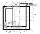
- FIG. 1is a side view of an illustrative embodiment of the device of the present invention.
- FIG. 2Ais a side view of one embodiment of a heat exchanger of the present invention.
- FIG. 2Bis a cross-sectional view of FIG. 2A , a front view of one embodiment of a device of the present invention.
- FIG. 3Aillustrates a side view of one embodiment of a heat exchanger of the present invention.
- FIG. 3Bis a cross-sectional view of FIG. 3A , one aspect of fluid flow through one embodiment of a heat exchanger of the device.
- FIG. 4is a top view of one embodiment of a device of the invention.
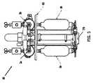
- FIG. 5is a depiction of a front view of the system.
- FIG. 1An external view of a device and system in accordance with one embodiment of the present invention is shown in FIG. 1 .
- the cryogenic system or device 30has sidewalls 17 which form a container that encloses an internal cavity, or lumen 15 .
- the containertakes the form of a vacuum insulated dewar 6 .
- the dewar 6stores liquid cryogen and interconnects a supply line 11 and return line 12 to a probe or catheter (not shown) to form a closed system 30 .
- the dewar 6may be made of material such as stainless steel or any other material known for providing a vacuum insulated vessel.
- the dewar 6is filled with liquid nitrogen or other liquefied gas (here, discussing as cryogen) to a maximum level 13 .
- liquid nitrogenmay be preferred.
- any fluidic cryogenmay be utilized (e.g. argon, oxygen, helium, hydrogen).
- a submersible pump 1which delivers the liquid cryogen to a sealed pressurization apparatus 40 .
- a valve 2controls the pressure fill into internal open chamber 42 of the pressurization apparatus 40 .
- an immersion heater 44housed in the internal open chamber 42 heats the cryogen to create a desired pressure.
- the liquid nitrogen within the pressurized chamberstarts at a temperature of about ⁇ 196° C. When the heater is activated, it boils the nitrogen within the immediate area. Temperature within internal cavity 42 therefore stays within about ⁇ 196° C. to ⁇ 150° C., more typically in the range of about ⁇ 196° C.
- cryogenis then released through a valve 32 into the baffled linear heat exchanger 4 .
- liquid nitrogenis converted to supercritical nitrogen (SCN) within the pressurization apparatus.
- SCNsupercritical nitrogen
- the SCNis then directed to the heat exchanger for subcooling and tuned to the liquid phase to attain an excess temperature. Thereafter, the SCN can be injected into one or more flexible cryoprobes such that the SCN flows with minimal friction to the tip of the probe.
- the baffled linear heat exchanger 4in one embodiment is surrounded by a subcooling chamber 3 which subcools the pressurized cryogen for delivery to external cryoprobes.
- the subcooling chamber 3in connection with the heat exchanger 4 at an entrance 23 and an exit opening 36 form an integral unit 51 for supplying subcooled liquid cryogen.
- the subcooled cryogenpasses into a supply line 11 and continues out through an exit port 35 and through a control valve 14 where various configurations of cryoprobes are attached.
- the subcooling chambermay attach a vent line to any of the vents 8 , to a supply connecting line 19 controlled through a valve 27 , or to a vacuum line 16 through a control valve 7 which is connected to a vacuum pump 18 .
- the cryogenis returned (as demonstrated by the arrows in FIG. 1 ) from the cryoprobe via a return tube 12 into a return chamber/cylinder 5 of the dewar 6 .
- the return tube 12connects into the return cylinder 5 which also surrounds the supply tube 11 that exits the heat exchanger 4 .
- One or more exit ports 35may be included in a side wall 17 of the dewar 6 or may be a separate unit 14 to incorporate various control valves.
- the device 30is filled through a supply port 29 and then sealed to form a closed system, thereby allowing for the supply, return, collection, and re-utilization of liquid cryogen during its utilization in the medical/surgical field.
- the entire system 30may or may not be pressurized during operation.
- the systemmay also be vented to the surrounding environment to prevent excess pressure buildup during operation.
- the returning cryogenempties into the return cylinder or chamber 5 .
- the returning cryogenmay empty as bulk fluid into the internal lumen 15 within the dewar 6 .
- the linear heat exchanger 4subcools the liquid cryogen prior to delivery to tissue.
- the linear heat exchanger 4passes through subcooling chamber 3 and is connected via the entrance 23 and exit opening 36 .
- Liquid cryogen passing through the linear heat exchanger 4is reduced in temperature to a subcooling degree by the outer subcooling chamber 3 .
- the chamber within a chamber configurationincludes a subcooling vacuum chamber 3 filled with liquid cryogen upon which a vacuum 18 is drawn through valve-controlled port 9 to reduce the atmospheric pressure on the cryogen. The temperature of the cryogen within the subcooling chamber 3 can then be reduced even further.
- the subcooling chamber 3also comprises valve controlled ports 8 external to the maximum liquid cryogen level for monitoring and electronically controlling temperatures, pressures, and flow rates of liquid cryogen passing through the subcooling unit.
- a vacuum 18can be drawn on vacuum line 16 at a controlled internal valve 7 or external valve 9 .
- valve controlled ports 8may be accessible for delivery of liquid cryogen to the subcooling chamber 3 by way of a supply line 19 or as a vent 8 for any excessive gas coming from the subcooling chamber 3 .
- the vacuum 18also is attached to the cryoprobe(s) by way of vacuum line 39 .
- FIGS. 2A , 2 B and FIGS. 3A , 3 BAspects of the linear heat exchanger 4 are illustrated in FIGS. 2A , 2 B and FIGS. 3A , 3 B.
- FIG. 2A and FIG. 3Aillustrate side views of different aspects of a linear baffled heat exchanger 4 and subcooling unit 3 as an integral unit 51 .
- FIG. 2Bdepicts a cross-section of FIG. 2A ;
- FIG. 2Bis a front view of the linear baffled heat exchanger 4 when looking into the linear heat exchanger 4 .
- An interior central component or spiral 20 within the interior lumen of the linear heat exchanger 4operates like a corkscrew to increase the flow path 25 of the liquid cryogen.
- An outer wall 22 of the linear heat exchanger 4also comprises baffles 24 which increase the surface area in the heat exchanger for quicker and reduced cooling of the liquid cryogen.
- baffles 24emanate into the flow path 25 (as illustrated by arrows) of the cryogen in the inner lumen, thereby increasing the surface area in the heat exchanger 4 .
- the spiral componentmay be any size and shape as to efficiently increase the flow of liquid cryogen. Planar structures, as described below, or any additional features included to increase surface area may be incorporated or substituted.
- FIG. 3Aillustrates another embodiment of a linear heat exchanger 4 such that the internal structure 20 has a planar configuration and also operates in a circular motion to increase the flow 25 of the liquid cryogen.
- FIG. 3Bdepicts a cross-section of FIG. 3A such that the inner tubular unit 21 assists the internal structure 20 in circulating the flow of liquid cryogen through the interior lumen of the linear heat exchanger 4 .
- One embodiment of the medical devicecomprises a return chamber 5 which is illustrated as a return cylinder 5 in FIG. 1 such that the return chamber 5 surrounds the supply line 11 coming from the heat exchanger 4 .
- the return chamber 5 and the surrounded supply linemay then provide a secondary heat exchanger for the system/medical device 30 .
- Cryogen returnis vented into the return chamber 5 .
- the return chamber 5comprises a series of vent holes 26 near the top of the return chamber 5 to allow for the venting of gas and/or liquid overflow into the main dewar 6 . Vent holes 26 allow for the reutilization of cryogen and thus extend the operation time for the medical device 30 .
- the return tube 12is vented into the main dewar 6 either directly or by first passing through a linear heat exchanger (similar to the combination of heat exchanger 4 and subcooling chamber 3 ) to subcool the return cryogen prior to venting into the main dewar 6 .
- a linear heat exchangersimilar to the combination of heat exchanger 4 and subcooling chamber 3
- Return of the cryogen to the main dewar 6allows the cryogen to return through a heat exchanger such that the cryogen is reutilized and extends the operation time even longer.
- the medical device 30may provide a system which is controlled through a series of computer controlled valves including any heaters, sensors, motors, or gauges.
- the sensorscontrol and monitor pressure, temperature, and fluid level in the dewar, and can measure any metric as may be desired.
- the sensorsmonitor pressure levels within defined safety ranges.
- the sensorsmay control the pressurization of one or more components internal to the dewar. Any of the valves 2 , 7 , 8 , 9 , 27 or 32 including exit portal valve 14 , may be automated to enable a controlled and consistent operation of the cryogenic system (e.g. computer controlled operation through the electronically controlled valves).
- FIG. 4An embodiment of a system 50 is shown in FIG. 4 .
- a series of six pulsatile pressurization chambers 40are sealed chambers/cylinders 40 within dewar 6 of the closed system 50 .
- liquid cryogenin pumped to the pulsatile pressurization chambers 40 which then delivers liquid cryogen in a continuous series of bursts to the heat exchanger 80 .
- the baffled linear heat exchanger 80provides an enhanced subcooling of the pressurized liquid cryogen while also incorporating an integral subcooling unit 3 .
- the chambers 40each comprising an individual immersion heater 44 , can then sequentially deliver liquid cryogen at consistent rates, or as specifically determined rates, to the heat exchanger 80 .
- the subcooled cryogenpasses into a supply line 11 and continues out through an exit port 35 where a control valve 14 is positioned and various configurations of cryoprobes are attached.
- the cryogenis returned (as demonstrated by the arrows in FIG. 4 ) via a return tube 12 from the cryoprobe to the dewar 6 into a return cylinder 5 .
- the return tube 12connects into the return cylinder which surrounds the supply tube 11 that exits the heat exchanger 80
- the entire system 50may or may not be pressurized during operation.
- the deviceis also vented through vent ports 8 to the surrounding environment to prevent excess pressure buildup during operation.
- a cryogenic system 50has been filled and detached from its cryogenic fill tank.
- the system 50is a separate mobile unit protected and contained entirely within an enclosed console for easy access and mobility. Once the system has been sealed, the cryogenic supply can be maintained for several procedures. The reutilization of the liquid cryogen provides a time savings and cost-efficient model for cryotherapeutic and cryosurgical procedures.
- the system 50can be further utilized for any process requiring rapid cooling.
- the system 50comprises a submersible liquid nitrogen pump 78 connected to a supply line 11 which directs the liquid nitrogen into a supply manifold 33 .
- the supply manifold 33routes the liquid nitrogen into at least one pulsatile pressurization chamber 40 where the liquid cryogen is heated.
- the pressurized liquid cryogenhere, liquid nitrogen
- the pressurized liquid cryogenthen starts filling the next pressurization cylinder/chamber 40 in the series such that when one chamber 40 is filling, another can be simultaneously pressurized and prepared for use. This permits a wave of activity through the cylinders so that it can cycle through each step of system operation.
- the pressurized cryogenis delivered to the heat exchanger 80 , and passes the subcooled pressurized cryogen out through the supply line 11 through the exit port 35 and into the attached cryoprobes, another pressurization chamber is filled and pressurized.
- the simultaneous use and pressurization of the liquid cryogenprovides for the sequential delivery of liquid cryogen in a continuous series of pulsations to a cryogenic instrument or probe.
- Each pressurization apparatus 40comprises a pressure valve controlled inlet 52 , valve controlled outlet 54 , and vent ports as may be desired, as well as an immersion heater 44 .
- the filling of the pressurization apparati 40is controlled through a series of pressure valves 52 on the supply manifold 33 .
- Liquid cryogenis heated within each pressurized apparatus. Pressurized liquid cryogen is then released through the control valve 54 to an outlet port/opening 46 of an outlet manifold 34 to the supply line 11 , and delivered to a baffled linear heat exchanger 80 .
- a subcooling unit 3surrounds the heat exchanger 80 for more rapid cooling.
- the cryogenic device 50comprises six pressurized apparati 40 linked together. Other embodiments, however, may comprise any number of pressurized apparati 40 individually or linked together in combination. The apparati can then be controlled individually or in sequence to deliver pressurized liquid cryogen to the heat exchanger 80 .
- one or more pressurization apparati 40may be arranged to supply one or more cryoprobes. Further, the series of pressurized apparati 40 may be interconnected with another series of apparati 40 .
- six pulsatile pressurization chambers 40are housed within a support network of a console.
- three of the cylinders within one-half of the dewarsimultaneously fill while three cylinders within the other half of the dewar deliver cryogen out through the outlet manifold.
- Liquid cryogenis heated in the sealed pressurization chambers 40 . Pressure is increased to a specified level in the sealed pressurization chambers 40 , and then the pressurized cryogen is controllably released into a heat exchanger 80 to subcool the cryogen.
- a subcooling vacuum chamber 3surrounds the heat exchanger 80 , facilitating the delivery of subcooled cryogen to an attached cryoprobe (also referred to as probe or catheter).
- a sensor within the heat exchangermonitors the temperature and pressure of the subcooled cryogen passing into supply line 11 as it continues out through an exit port 35 where various configurations of cryoprobes are attached.
- the systemmay fill or discharge each cylinder 40 individually, any simultaneous fill or discharge, or rate of fill or discharge, may be incorporated into the system.
- the closed systemkeeps a constant supply of liquid nitrogen available for delivery to the cryoprobe and provides a more immediate and rapid rate of cooling for cryotherapeutic procedures. It is therefore possible to close the supply port 29 where supply tanks fill the dewar (See FIG. 1 and FIG. 4 ) and move the system to any locale or setting.
- the supply valve 2may be closed and the release valve 14 opened to create a flow of liquid cryogen to the cryoprobe.
- Various arrangements of valves and sensorsmay therefore provide for similar flow.
- the pressurized chambers 40are filled and the dewar sealed.
- a single drive pumpperpetuates directional flow of the cryogen into the pressurization chambers.
- all chamberscan be filled through various configurations of single direction pumping.
- a reversible pump and fill methodallows one pressurized chamber 40 to fill and then the pump flips or reverses functionality to fill another pressurized chamber. This process can be repeated to fill any number of chambers.
- pressurized chambers 40are enclosed completely within the dewar 6 .
- any arrangement of the pressurized cylindersis possible so long as the closed system provides for the pulsatile delivery of cryogen to the cryoprobe.
- any single or multiple configurations of cryoprobes or cathetersmay be used.
- Such instrumentsmay also include cryoguns or cryodevices for rapid cryo-delivery processes or cryotherapies.
- an immersible liquid cryogen pump 79is activated to fill each cryogen supply cylinder 2 a & 2 b , or cartridge, sequentially.
- one cartridge 2 ais filled along with its linked cryogen pressurization cartridge 3 a .
- Cryogenic solenoid valvesprovide venting of the gas within the cartridge assembly to support filling.
- the cryogen pressurization cartridge 3 ais heated to generate a pressure of about 1000 psi (68 bar).
- the SCNBy converting liquid nitrogen to SCN in a cartridge cooled by atmospheric liquid nitrogen ( ⁇ 196° C.), the SCN is subcooled and tuned to the liquid phase, attaining an excess temperature (i.e. the ability to absorb heat without boiling) of approximately 50° C.
- the SCNWhen the SCN is injected into the flexible cryoprobe, the SCN flows with minimal friction to the tip of the probe (boiling chamber). In the tip, SCN pressure drops due to an increased volume and outflow restriction, heat is absorbed (nucleate boiling) along the inner surface of the TIP, micro bubbles of nitrogen gas condense back into a liquid, and the warmed SCN reverts to pressurized liquid nitrogen as it exits the return tube and resupplies the dewar containing atmospheric liquid nitrogen.
- This flow dynamicoccurs within a few seconds and is regulated by a high pressure solenoid valve.
- the processis repeated with the second cartridge subassembly ( 2 b & 3 b ).
- liquid nitrogenAs demonstrated by FIG. 5 , the limitations of liquid nitrogen have been overcome by developing a novel device to convert atmospheric liquid nitrogen to supercritical nitrogen. Where liquid nitrogen was previously delivered through large tubes and did not provide for rapid delivery, the current system herein described allows for rapid delivery of liquid cryogens through very small tubing.
- the SCNcan be injected or drawn through two plus meters of hypodermic tubing without boiling, thereby resulting in near instantaneous ice formation at the tip to target site specific ablation of tissue as well as the creation of transmural lesions without the formation of a thrombus or aneurysm.
- Supercritical nitrogenis a dense fluid with properties of both gas and liquid that can be tuned toward one phase or the other. In the liquid phase, SCN lacks surface tension and transports without friction.
- the above-described technologygenerates SCN in a pressurized cartridge immersed in atmospheric liquid nitrogen.
- This cryoenginewhich operates as a cryogen generator, produces SCN in the liquid phase with a boiling point of about ⁇ 149° C. which is subcooled by the surrounding atmospheric liquid nitrogen to about ⁇ 196° C.
- the SCNpasses instantly through the system without the phase transition to a gas due to both the frictionless flow and the subcooling which compensates for parasitic heat gain along the path.
- the embodiment of FIG. 5may be utilized in any supercooling system or in directing flow of liquid cryogen through to a cryo-instrument.
- the supercritical pointwill be determined by the chemistry of the specified liquid or gas used. Therefore, the system can be adjusted to accommodate for differences in chemistry.
- the embodiments of the present inventionare for exemplary purposes only and not limitation.
- this devicerepresents an important step in targeted thermal therapies.
- Various cryosurgical devices and procedures to apply freezing temperatures to a target tissuemay be employed for use with the medical device of the present invention.
- the medical device of the present inventionhas been developed to enable and improve some of the approaches used to target or ablate tissue.
- the medical devicecan couple controlled pumping of a liquid cryogen through a baffled linear heat exchanger to decrease the overall temperature of the cryogen providing a greater heat capacity of the fluid and thereby resulting in an increased cooling potential in a cryoprobe.
- the inventionfacilitates other improvements in cryotherapy, and medical devices or components associated with the treatment.
- the medical device of the inventionallows for the circulation (cooling, delivery, and return) of liquid cryogen to a cryoprobe for the freezing of targeted tissue.
- the inventionfacilitates the eradication of tissue and can thereby decrease hospitalization time; and further limit postoperative morbidities, shorten return to daily functions and work, and further reduce the overall treatment cost.
- the current devicerepresents an improved development of cryosurgical devices by allowing for controlled linear flow of a cryogen without the need for high pressure or compression based bellows or piston systems. Further, the device contains a novel baffled linear heat exchanger designed for cryogen flow through a specialized subcooling chamber.
- the embodiments of the present inventionmay be modified to take the shape of any device, container, apparatus, or vessel currently used in industry.
- cylindrical or alternative vesselsmay provide containers for the cryogenic system for improved cryogenic supply and delivery.
- any compartmental arrangement in combination with the components of the above systemmay take many forms and be of any size, shape, or passageway. Any number of vents may also be utilized to facilitate operation of the system.
- the systemmay also be a partially closed or completely closed system.
- the deviceis contained within a console, a shell or enclosure that allows the system to be easily transported.
- the enclosuremay then include any mobile feature such as wheels, handles, and fixtures (or allow placement onto a cart having these features) so that the system can be transported to and from the location of treatment.
- Such mobilityallows the system to be easily moved to and from an operating room or site of therapeutic treatment.
- the systemis readily separable from the cryogen fill tanks and fill lines that initially supply the system with the liquid nitrogen or other such cryogenic fluid at the supply port 29 (As shown in FIG. 1 ). This improved feature eliminates the bulkiness of standard cryogenic medical devices.
- the multiple embodiments of the present inventionoffer several improvements over standard medical devices currently used in cryogenic industry.
- the improved cryogenic medical devicesremarkably enhance its utilization for the cooling, delivery and return of a liquid cryogen to a cryoprobe for the freezing of targeted tissue.
- the present inventionprovides cost savings and significantly reduced treatment times which further reduce expenditures in the healthcare setting.
- the previously unforeseen benefitshave been realized and conveniently offer advantages for the treatment of multiple disease states.
- the improvementsenable construction of the device as designed to enable easy handling, storage, and accessibility. Further uses of the system outside of the healthcare setting are foreseeable. Potential uses in the space industry, defense systems or any industry requiring rapid cooling may incorporate the cryogenic system as thus described.
- the devicemay include any unitary structure, vessel, device or flask with the capacity to integrally incorporate any combination of such structures.
Landscapes
- Engineering & Computer Science (AREA)
- Health & Medical Sciences (AREA)
- Mechanical Engineering (AREA)
- General Engineering & Computer Science (AREA)
- Surgery (AREA)
- Physics & Mathematics (AREA)
- Thermal Sciences (AREA)
- Life Sciences & Earth Sciences (AREA)
- Nuclear Medicine, Radiotherapy & Molecular Imaging (AREA)
- Chemical & Material Sciences (AREA)
- Combustion & Propulsion (AREA)
- Otolaryngology (AREA)
- Biomedical Technology (AREA)
- Heart & Thoracic Surgery (AREA)
- Medical Informatics (AREA)
- Molecular Biology (AREA)
- Animal Behavior & Ethology (AREA)
- General Health & Medical Sciences (AREA)
- Public Health (AREA)
- Veterinary Medicine (AREA)
- Thermotherapy And Cooling Therapy Devices (AREA)
Abstract
Description
Claims (20)
Priority Applications (1)
| Application Number | Priority Date | Filing Date | Title |
|---|---|---|---|
| US12/821,274US8998888B2 (en) | 2008-09-03 | 2010-06-23 | Modular pulsed pressure device for the transport of liquid cryogen to a cryoprobe |
Applications Claiming Priority (3)
| Application Number | Priority Date | Filing Date | Title |
|---|---|---|---|
| US9391608P | 2008-09-03 | 2008-09-03 | |
| US12/553,005US9408654B2 (en) | 2008-09-03 | 2009-09-02 | Modular pulsed pressure device for the transport of liquid cryogen to a cryoprobe |
| US12/821,274US8998888B2 (en) | 2008-09-03 | 2010-06-23 | Modular pulsed pressure device for the transport of liquid cryogen to a cryoprobe |
Related Parent Applications (1)
| Application Number | Title | Priority Date | Filing Date |
|---|---|---|---|
| US12/553,005ContinuationUS9408654B2 (en) | 2008-09-03 | 2009-09-02 | Modular pulsed pressure device for the transport of liquid cryogen to a cryoprobe |
Publications (2)
| Publication Number | Publication Date |
|---|---|
| US20100256622A1 US20100256622A1 (en) | 2010-10-07 |
| US8998888B2true US8998888B2 (en) | 2015-04-07 |
Family
ID=41726480
Family Applications (4)
| Application Number | Title | Priority Date | Filing Date |
|---|---|---|---|
| US12/553,005Active2032-03-29US9408654B2 (en) | 2008-09-03 | 2009-09-02 | Modular pulsed pressure device for the transport of liquid cryogen to a cryoprobe |
| US12/821,274Active2032-03-27US8998888B2 (en) | 2008-09-03 | 2010-06-23 | Modular pulsed pressure device for the transport of liquid cryogen to a cryoprobe |
| US15/230,096AbandonedUS20160338754A1 (en) | 2008-09-03 | 2016-08-05 | Modular pulsed pressure device for the transport of liquid cryogen to a cryoprobe |
| US16/687,651Active2032-11-06US11963707B2 (en) | 2008-09-03 | 2019-11-18 | Modular pulsed pressure device for the transport of liquid cryogen to a cryoprobe |
Family Applications Before (1)
| Application Number | Title | Priority Date | Filing Date |
|---|---|---|---|
| US12/553,005Active2032-03-29US9408654B2 (en) | 2008-09-03 | 2009-09-02 | Modular pulsed pressure device for the transport of liquid cryogen to a cryoprobe |
Family Applications After (2)
| Application Number | Title | Priority Date | Filing Date |
|---|---|---|---|
| US15/230,096AbandonedUS20160338754A1 (en) | 2008-09-03 | 2016-08-05 | Modular pulsed pressure device for the transport of liquid cryogen to a cryoprobe |
| US16/687,651Active2032-11-06US11963707B2 (en) | 2008-09-03 | 2019-11-18 | Modular pulsed pressure device for the transport of liquid cryogen to a cryoprobe |
Country Status (1)
| Country | Link |
|---|---|
| US (4) | US9408654B2 (en) |
Cited By (4)
| Publication number | Priority date | Publication date | Assignee | Title |
|---|---|---|---|---|
| EP3868320A1 (en) | 2020-02-10 | 2021-08-25 | IceCure Medical Ltd. | Cryogen pump |
| US11771486B2 (en) | 2017-01-17 | 2023-10-03 | Corfigo, Inc. | Device for ablation of tissue surfaces and related systems and methods |
| US12215811B2 (en) | 2022-07-18 | 2025-02-04 | Icecure Medical Ltd. | Cryogenic system connector |
| US12426934B2 (en) | 2022-02-28 | 2025-09-30 | Icecure Medical Ltd. | Cryogen flow control |
Families Citing this family (28)
| Publication number | Priority date | Publication date | Assignee | Title |
|---|---|---|---|---|
| US8784409B2 (en)* | 2008-09-03 | 2014-07-22 | Endocare, Inc. | Cryogenic system and method of use |
| US9089316B2 (en) | 2009-11-02 | 2015-07-28 | Endocare, Inc. | Cryogenic medical system |
| US9408654B2 (en) | 2008-09-03 | 2016-08-09 | Endocare, Inc. | Modular pulsed pressure device for the transport of liquid cryogen to a cryoprobe |
| US10182859B2 (en)* | 2008-09-03 | 2019-01-22 | Endocare, Inc. | Medical device for the transport of subcooled cryogenic fluid through a linear heat exchanger |
| US8298219B2 (en)* | 2009-09-02 | 2012-10-30 | Medtronic Cryocath Lp | Cryotreatment device using a supercritical gas |
| WO2013013099A1 (en)* | 2011-07-19 | 2013-01-24 | Adagio Medical, Inc. | Methods and devices for the treatment of atrial fibrillation |
| US9301796B2 (en)* | 2012-03-02 | 2016-04-05 | Csa Medical, Inc. | Cryosurgery system |
| US9144449B2 (en) | 2012-03-02 | 2015-09-29 | Csa Medical, Inc. | Cryosurgery system |
| US9243726B2 (en) | 2012-10-03 | 2016-01-26 | Aarne H. Reid | Vacuum insulated structure with end fitting and method of making same |
| CA2904190C (en) | 2013-03-04 | 2022-08-16 | Csa Medical, Inc. | Cryospray catheters |
| US10001313B2 (en)* | 2013-09-09 | 2018-06-19 | Inovatzia, Inc. | Reusable cryogenic carrying case for biological materials |
| MX390311B (en) | 2013-12-05 | 2025-03-20 | Rfemb Holdings Llc | PRESENTATION OF ENHANCED CANCER ANTIGEN TO CELLS PRESENTING BY ELECTRICAL MEMBRANE BREAKDOWN BY RADIOFREQUENCY (RF-RMB) AS AN ADJUVANT MECHANISM FOR IMMUNOTHERAPY. |
| US9463918B2 (en) | 2014-02-20 | 2016-10-11 | Aarne H. Reid | Vacuum insulated articles and methods of making same |
| CA2951050A1 (en) | 2014-06-04 | 2015-12-10 | Csa Medical, Inc. | Method and system for consistent, repeatable, and safe cryospray treatment of airway tissue |
| US10497908B2 (en) | 2015-08-24 | 2019-12-03 | Concept Group, Llc | Sealed packages for electronic and energy storage devices |
| US10065256B2 (en) | 2015-10-30 | 2018-09-04 | Concept Group Llc | Brazing systems and methods |
| US11612426B2 (en)* | 2016-01-15 | 2023-03-28 | Immunsys, Inc. | Immunologic treatment of cancer |
| CN109154641B (en) | 2016-03-04 | 2021-09-17 | 概念集团有限责任公司 | Vacuum insulation article with reflective material enhancement |
| JP6820121B2 (en) | 2016-04-27 | 2021-01-27 | シーエスエー メディカル, インコーポレイテッド | Vision-securing device for medical devices |
| US11871977B2 (en) | 2016-05-19 | 2024-01-16 | Csa Medical, Inc. | Catheter extension control |
| WO2018093773A1 (en) | 2016-11-15 | 2018-05-24 | Reid Aarne H | Multiply-insulated assemblies |
| CA3043915A1 (en) | 2016-11-15 | 2018-05-24 | Concept Group Llc | Enhanced vacuum-insulated articles with microporous insulation |
| US11320086B2 (en) | 2017-08-25 | 2022-05-03 | Concept Group Llc | Multiple geometry and multiple material insulated components |
| WO2019195791A1 (en)* | 2018-04-05 | 2019-10-10 | Xu Han | Improved ultra-fast cooling system and methods of use |
| US12070526B2 (en) | 2020-05-14 | 2024-08-27 | Cpsi Holdings Llc | Cryogenic disinfection system and method |
| CN115363737B (en)* | 2021-07-22 | 2024-09-17 | 海杰亚(北京)医疗器械有限公司 | Electric control system for tumor minimally invasive treatment |
| US20230381015A1 (en)* | 2022-05-31 | 2023-11-30 | Icecure Medical Ltd. | Cryogenic system with multiple submerged pumps |
| US20250090215A1 (en)* | 2023-09-20 | 2025-03-20 | Varian Medical Systems, Inc. | Apparatuses and methods for cryogen measurement and control for cryoablation systems |
Citations (46)
| Publication number | Priority date | Publication date | Assignee | Title |
|---|---|---|---|---|
| US3794039A (en) | 1969-10-25 | 1974-02-26 | Linde Ag | Apparatus for cryosurgery |
| US4082096A (en) | 1973-12-10 | 1978-04-04 | Benson Jerrel W | Cryosurgical system |
| US4377168A (en) | 1981-02-27 | 1983-03-22 | Wallach Surgical Instruments, Inc. | Cryosurgical instrument |
| US4829785A (en) | 1987-12-04 | 1989-05-16 | The Boeing Company | Cryogenic cooling system with precooling stage |
| US5147355A (en) | 1988-09-23 | 1992-09-15 | Brigham And Womens Hospital | Cryoablation catheter and method of performing cryoablation |
| US5237824A (en) | 1989-02-16 | 1993-08-24 | Pawliszyn Janusz B | Apparatus and method for delivering supercritical fluid |
| US5334181A (en) | 1990-09-26 | 1994-08-02 | Cryomedical Sciences, Inc. | Cryosurgical system for destroying tumors by freezing |
| US5423807A (en) | 1992-04-16 | 1995-06-13 | Implemed, Inc. | Cryogenic mapping and ablation catheter |
| US5452582A (en) | 1994-07-06 | 1995-09-26 | Apd Cryogenics, Inc. | Cryo-probe |
| US5733280A (en) | 1995-11-15 | 1998-03-31 | Avitall; Boaz | Cryogenic epicardial mapping and ablation |
| US5746736A (en) | 1995-08-09 | 1998-05-05 | Lumedics, Ltd. | Cryogenic laser lithotripsy with enhanced light absorption |
| US5758505A (en) | 1995-10-12 | 1998-06-02 | Cryogen, Inc. | Precooling system for joule-thomson probe |
| US5916212A (en) | 1998-01-23 | 1999-06-29 | Cryomedical Sciences, Inc. | Hand held cyrosurgical probe system |
| US5951546A (en) | 1994-12-13 | 1999-09-14 | Lorentzen; Torben | Electrosurgical instrument for tissue ablation, an apparatus, and a method for providing a lesion in damaged and diseased tissue from a mammal |
| US6096032A (en) | 1996-08-14 | 2000-08-01 | Rowland; Stephen James | Medical cryo-surgical device |
| US6161543A (en) | 1993-02-22 | 2000-12-19 | Epicor, Inc. | Methods of epicardial ablation for creating a lesion around the pulmonary veins |
| US6171301B1 (en) | 1994-04-05 | 2001-01-09 | The Regents Of The University Of California | Apparatus and method for dynamic cooling of biological tissues for thermal mediated surgery |
| US20010021847A1 (en) | 1999-01-25 | 2001-09-13 | Marwan Abboud | Cooling system |
| US6306129B1 (en) | 1997-09-22 | 2001-10-23 | Femrx, Inc. | Cryosurgical system and method |
| US6468269B1 (en) | 1999-03-02 | 2002-10-22 | Nikolai Korpan | Cryogenic system, especially for performing cryosurgical surgery |
| US6468268B1 (en) | 1999-01-25 | 2002-10-22 | Cryocath Technologies Inc. | Cryogenic catheter system |
| US20030055416A1 (en) | 2001-09-20 | 2003-03-20 | Damasco Sanford D. | Cryosurgical probe with bellows shaft |
| US20040215295A1 (en) | 2003-01-15 | 2004-10-28 | Mediphysics Llp | Cryotherapy system |
| US20050090814A1 (en) | 1999-01-25 | 2005-04-28 | Jean-Pierre Lalonde | Cooling system |
| US20050261753A1 (en) | 2003-01-15 | 2005-11-24 | Mediphysics Llp | Methods and systems for cryogenic cooling |
| US20050261671A1 (en) | 2001-05-31 | 2005-11-24 | Baust John G | Cryogenic system |
| US20060079867A1 (en) | 2003-04-03 | 2006-04-13 | Nir Berzak | Apparatus and method for accurately delimited cryoablation |
| US20060129142A1 (en) | 2004-12-15 | 2006-06-15 | Cryovascular Systems, Inc. | Efficient controlled cryogenic fluid delivery into a balloon catheter and other treatment devices |
| US7160291B2 (en) | 2003-06-25 | 2007-01-09 | Endocare, Inc. | Detachable cryosurgical probe |
| US20070021741A1 (en) | 2003-07-11 | 2007-01-25 | Cryocath Technologies Inc. | Method and device for epicardial ablation |
| US7207985B2 (en) | 2003-06-25 | 2007-04-24 | Endocare, Inc. | Detachable cryosurgical probe |
| US20070244474A1 (en) | 2006-04-18 | 2007-10-18 | Sanarus Medical, Inc. | Cryosurgical system |
| US20070277550A1 (en) | 2000-08-09 | 2007-12-06 | Cryocor, Inc. | Refrigeration source for a cryoablation catheter |
| US7306589B2 (en) | 2003-04-24 | 2007-12-11 | Boston Scientific Scimed, Inc. | Therapeutic apparatus having insulated region at the insertion area |
| US20080009845A1 (en) | 2003-06-25 | 2008-01-10 | Endocare, Inc. | Cryosurgical probe with adjustable sliding apparatus |
| US20080027422A1 (en) | 2006-07-25 | 2008-01-31 | Ams Research Corporation | Closed-Loop Cryosurgical System and Cryoprobe |
| US20080147056A1 (en) | 2006-07-14 | 2008-06-19 | Micrablate | Energy delivery systems and uses thereof |
| US7416551B2 (en) | 2003-07-28 | 2008-08-26 | A.F.M. Medical Systems Ltd. | Catheter for delivering a tissue ablation probe |
| US20080255551A1 (en) | 2007-04-16 | 2008-10-16 | Sanarus Medical, Inc. | Cryosurgical System with Low Pressure Cryogenic Fluid Supply |
| US20080300584A1 (en) | 2007-06-01 | 2008-12-04 | Lentz David J | Cryoablation segment for creating linear lesions |
| US20090012510A1 (en) | 2001-12-04 | 2009-01-08 | Endoscopic Technologies, Inc. | Cardiac ablation devices and methods |
| US20090281533A1 (en) | 2008-05-12 | 2009-11-12 | Boston Scientific Scimed, Inc. | Apparatus and method for chilling cryo-ablation coolant and resulting cryo-ablation system |
| US20100057067A1 (en)* | 2008-09-03 | 2010-03-04 | Baust John M | Modular pulsed pressure device for the transport of liquid cryogen to a cryoprobe |
| US20100057064A1 (en)* | 2008-09-03 | 2010-03-04 | Baust John M | Medical Device for the Transport of Subcooled Cryogenic Fluid through a Linear Heat Exchanger |
| WO2010028409A1 (en) | 2008-09-03 | 2010-03-11 | Dobson, Melissa, K. | A cryogenic system and method of use |
| US20100241112A1 (en) | 2009-03-23 | 2010-09-23 | Boston Scientific Scimed, Inc. | Systems apparatus and methods for distributing coolant within a cryo-ablation device |
Family Cites Families (5)
| Publication number | Priority date | Publication date | Assignee | Title |
|---|---|---|---|---|
| US3295599A (en)* | 1962-04-23 | 1967-01-03 | Nihon Genshiryoku Kenkyujo | Heat transfer fin heat exchanging tube |
| KR0144165B1 (en)* | 1995-05-12 | 1998-07-01 | 문정환 | Improved Manufacturing Method of Inverse Tee (T) Transistor |
| US6789545B2 (en)* | 2002-10-04 | 2004-09-14 | Sanarus Medical, Inc. | Method and system for cryoablating fibroadenomas |
| KR100970717B1 (en)* | 2007-03-26 | 2010-07-16 | 주식회사 예스바이오 | Bone Membrane Induction Shield |
| US20110225988A1 (en)* | 2010-03-17 | 2011-09-22 | Cpsi Biotech | Multi-Lumen Axial Cryogenic Connector |
- 2009
- 2009-09-02USUS12/553,005patent/US9408654B2/enactiveActive
- 2010
- 2010-06-23USUS12/821,274patent/US8998888B2/enactiveActive
- 2016
- 2016-08-05USUS15/230,096patent/US20160338754A1/ennot_activeAbandoned
- 2019
- 2019-11-18USUS16/687,651patent/US11963707B2/enactiveActive
Patent Citations (56)
| Publication number | Priority date | Publication date | Assignee | Title |
|---|---|---|---|---|
| US3794039A (en) | 1969-10-25 | 1974-02-26 | Linde Ag | Apparatus for cryosurgery |
| US4082096A (en) | 1973-12-10 | 1978-04-04 | Benson Jerrel W | Cryosurgical system |
| US4377168A (en) | 1981-02-27 | 1983-03-22 | Wallach Surgical Instruments, Inc. | Cryosurgical instrument |
| US4829785A (en) | 1987-12-04 | 1989-05-16 | The Boeing Company | Cryogenic cooling system with precooling stage |
| US5147355A (en) | 1988-09-23 | 1992-09-15 | Brigham And Womens Hospital | Cryoablation catheter and method of performing cryoablation |
| US5237824A (en) | 1989-02-16 | 1993-08-24 | Pawliszyn Janusz B | Apparatus and method for delivering supercritical fluid |
| US5334181A (en) | 1990-09-26 | 1994-08-02 | Cryomedical Sciences, Inc. | Cryosurgical system for destroying tumors by freezing |
| US5674218A (en) | 1990-09-26 | 1997-10-07 | Cryomedical Sciences, Inc. | Cryosurgical instrument and system and method of cryosurgery |
| US5423807A (en) | 1992-04-16 | 1995-06-13 | Implemed, Inc. | Cryogenic mapping and ablation catheter |
| US6161543A (en) | 1993-02-22 | 2000-12-19 | Epicor, Inc. | Methods of epicardial ablation for creating a lesion around the pulmonary veins |
| US6171301B1 (en) | 1994-04-05 | 2001-01-09 | The Regents Of The University Of California | Apparatus and method for dynamic cooling of biological tissues for thermal mediated surgery |
| US5452582A (en) | 1994-07-06 | 1995-09-26 | Apd Cryogenics, Inc. | Cryo-probe |
| US5951546A (en) | 1994-12-13 | 1999-09-14 | Lorentzen; Torben | Electrosurgical instrument for tissue ablation, an apparatus, and a method for providing a lesion in damaged and diseased tissue from a mammal |
| US5746736A (en) | 1995-08-09 | 1998-05-05 | Lumedics, Ltd. | Cryogenic laser lithotripsy with enhanced light absorption |
| US5758505C1 (en) | 1995-10-12 | 2001-10-30 | Cryogen Inc | Precooling system for joule-thomson probe |
| US5758505A (en) | 1995-10-12 | 1998-06-02 | Cryogen, Inc. | Precooling system for joule-thomson probe |
| US5733280A (en) | 1995-11-15 | 1998-03-31 | Avitall; Boaz | Cryogenic epicardial mapping and ablation |
| US6096032A (en) | 1996-08-14 | 2000-08-01 | Rowland; Stephen James | Medical cryo-surgical device |
| US6306129B1 (en) | 1997-09-22 | 2001-10-23 | Femrx, Inc. | Cryosurgical system and method |
| US5916212A (en) | 1998-01-23 | 1999-06-29 | Cryomedical Sciences, Inc. | Hand held cyrosurgical probe system |
| US6468268B1 (en) | 1999-01-25 | 2002-10-22 | Cryocath Technologies Inc. | Cryogenic catheter system |
| US20010021847A1 (en) | 1999-01-25 | 2001-09-13 | Marwan Abboud | Cooling system |
| US20050090814A1 (en) | 1999-01-25 | 2005-04-28 | Jean-Pierre Lalonde | Cooling system |
| US6887234B2 (en) | 1999-01-25 | 2005-05-03 | Cryocath Technologies Inc. | Cryogenic catheter system |
| US20070233055A1 (en) | 1999-01-25 | 2007-10-04 | Cryocath Technologies Inc. | Cooling system |
| US7303554B2 (en) | 1999-01-25 | 2007-12-04 | Cryocath Technologies Inc. | Closed loop catheter coolant system |
| US6468269B1 (en) | 1999-03-02 | 2002-10-22 | Nikolai Korpan | Cryogenic system, especially for performing cryosurgical surgery |
| US20090318913A1 (en) | 2000-08-09 | 2009-12-24 | Hong Li | Refrigeration source for a cryoablation catheter |
| US20070277550A1 (en) | 2000-08-09 | 2007-12-06 | Cryocor, Inc. | Refrigeration source for a cryoablation catheter |
| US20050261671A1 (en) | 2001-05-31 | 2005-11-24 | Baust John G | Cryogenic system |
| US7416548B2 (en) | 2001-05-31 | 2008-08-26 | Endocare, Inc. | Cryogenic system |
| US20030055416A1 (en) | 2001-09-20 | 2003-03-20 | Damasco Sanford D. | Cryosurgical probe with bellows shaft |
| US20090012510A1 (en) | 2001-12-04 | 2009-01-08 | Endoscopic Technologies, Inc. | Cardiac ablation devices and methods |
| US20050261753A1 (en) | 2003-01-15 | 2005-11-24 | Mediphysics Llp | Methods and systems for cryogenic cooling |
| US20040215295A1 (en) | 2003-01-15 | 2004-10-28 | Mediphysics Llp | Cryotherapy system |
| US20060235375A1 (en) | 2003-01-15 | 2006-10-19 | Cryodynamics, Llc | Cryotherapy system |
| US20080173028A1 (en) | 2003-01-15 | 2008-07-24 | Cryodynamics, Llc | Methods and systems for cryogenic cooling |
| US20060079867A1 (en) | 2003-04-03 | 2006-04-13 | Nir Berzak | Apparatus and method for accurately delimited cryoablation |
| US7306589B2 (en) | 2003-04-24 | 2007-12-11 | Boston Scientific Scimed, Inc. | Therapeutic apparatus having insulated region at the insertion area |
| US7207985B2 (en) | 2003-06-25 | 2007-04-24 | Endocare, Inc. | Detachable cryosurgical probe |
| US7160291B2 (en) | 2003-06-25 | 2007-01-09 | Endocare, Inc. | Detachable cryosurgical probe |
| US20080009845A1 (en) | 2003-06-25 | 2008-01-10 | Endocare, Inc. | Cryosurgical probe with adjustable sliding apparatus |
| US20070021741A1 (en) | 2003-07-11 | 2007-01-25 | Cryocath Technologies Inc. | Method and device for epicardial ablation |
| US7416551B2 (en) | 2003-07-28 | 2008-08-26 | A.F.M. Medical Systems Ltd. | Catheter for delivering a tissue ablation probe |
| US20060129142A1 (en) | 2004-12-15 | 2006-06-15 | Cryovascular Systems, Inc. | Efficient controlled cryogenic fluid delivery into a balloon catheter and other treatment devices |
| US20070244474A1 (en) | 2006-04-18 | 2007-10-18 | Sanarus Medical, Inc. | Cryosurgical system |
| US20080147056A1 (en) | 2006-07-14 | 2008-06-19 | Micrablate | Energy delivery systems and uses thereof |
| US20080027422A1 (en) | 2006-07-25 | 2008-01-31 | Ams Research Corporation | Closed-Loop Cryosurgical System and Cryoprobe |
| US20080255551A1 (en) | 2007-04-16 | 2008-10-16 | Sanarus Medical, Inc. | Cryosurgical System with Low Pressure Cryogenic Fluid Supply |
| US20080300584A1 (en) | 2007-06-01 | 2008-12-04 | Lentz David J | Cryoablation segment for creating linear lesions |
| US20090281533A1 (en) | 2008-05-12 | 2009-11-12 | Boston Scientific Scimed, Inc. | Apparatus and method for chilling cryo-ablation coolant and resulting cryo-ablation system |
| US20100057067A1 (en)* | 2008-09-03 | 2010-03-04 | Baust John M | Modular pulsed pressure device for the transport of liquid cryogen to a cryoprobe |
| US20100057064A1 (en)* | 2008-09-03 | 2010-03-04 | Baust John M | Medical Device for the Transport of Subcooled Cryogenic Fluid through a Linear Heat Exchanger |
| WO2010028409A1 (en) | 2008-09-03 | 2010-03-11 | Dobson, Melissa, K. | A cryogenic system and method of use |
| US20110152849A1 (en)* | 2008-09-03 | 2011-06-23 | Baust John M | Cryogenic System and Method of Use |
| US20100241112A1 (en) | 2009-03-23 | 2010-09-23 | Boston Scientific Scimed, Inc. | Systems apparatus and methods for distributing coolant within a cryo-ablation device |
Non-Patent Citations (3)
| Title |
|---|
| Bartlett, The Fundamentals of Heat Exchangers, Industrial Physicist (2006) 18-21. |
| Fladerer et al. "Homogenous nucleation and droplet growth in supersaturated argon vapor: The cryogenic nucleation pulse chamber," Journal of Chemical Physics (2006), vol. 124. 2006 American Institute of Physics. USA. |
| Office Action dated Feb. 20, 2013 received in related U.S. Appl. No. 12/548,321. |
Cited By (5)
| Publication number | Priority date | Publication date | Assignee | Title |
|---|---|---|---|---|
| US11771486B2 (en) | 2017-01-17 | 2023-10-03 | Corfigo, Inc. | Device for ablation of tissue surfaces and related systems and methods |
| EP3868320A1 (en) | 2020-02-10 | 2021-08-25 | IceCure Medical Ltd. | Cryogen pump |
| US11633224B2 (en) | 2020-02-10 | 2023-04-25 | Icecure Medical Ltd. | Cryogen pump |
| US12426934B2 (en) | 2022-02-28 | 2025-09-30 | Icecure Medical Ltd. | Cryogen flow control |
| US12215811B2 (en) | 2022-07-18 | 2025-02-04 | Icecure Medical Ltd. | Cryogenic system connector |
Also Published As
| Publication number | Publication date |
|---|---|
| US9408654B2 (en) | 2016-08-09 |
| US20100256622A1 (en) | 2010-10-07 |
| US20160338754A1 (en) | 2016-11-24 |
| US20200138500A1 (en) | 2020-05-07 |
| US20100057067A1 (en) | 2010-03-04 |
| US11963707B2 (en) | 2024-04-23 |
Similar Documents
| Publication | Publication Date | Title |
|---|---|---|
| US11963707B2 (en) | Modular pulsed pressure device for the transport of liquid cryogen to a cryoprobe | |
| US20200121498A1 (en) | Cryogenic System and Method of Use | |
| US8784409B2 (en) | Cryogenic system and method of use | |
| US12000536B2 (en) | Pressurized sub-cooled cryogenic system and method of use | |
| US10182859B2 (en) | Medical device for the transport of subcooled cryogenic fluid through a linear heat exchanger | |
| US11849989B2 (en) | Cryogenic system and methods | |
| US9974592B2 (en) | Cryogenic medical system | |
| US20040215295A1 (en) | Cryotherapy system | |
| EP3173041B1 (en) | A cryogenic system | |
| JP2023177307A (en) | Cryogenic system with multiple submerged pumps |
Legal Events
| Date | Code | Title | Description |
|---|---|---|---|
| AS | Assignment | Owner name:CPSI HOLDINGS LLC, NEW YORK Free format text:ASSIGNMENT OF ASSIGNORS INTEREST;ASSIGNORS:BAUST, JOHN M;ROBILOTTO, ANTHONY;SNYDER, KRISTI K.;AND OTHERS;REEL/FRAME:027154/0778 Effective date:20111031 | |
| AS | Assignment | Owner name:CPSI HOLDINGS LLC, NEW YORK Free format text:CORRECTIVE ASSIGNMENT TO CORRECT THE (REMOVAL) OF AN ASSIGNOR AND CORRECT 'CORRESPONDENT NAME' PREVIOUSLY RECORDED ON REEL 027154 FRAME 0778. ASSIGNOR(S) HEREBY CONFIRMS THE ASSIGNMENT;ASSIGNORS:BAUST, JOHN M.;CHEEKS, ROY E.;BAUST, JOHN G.;AND OTHERS;REEL/FRAME:027284/0429 Effective date:20111031 | |
| AS | Assignment | Owner name:ENDO PHARMACEUTICALS INC., PENNSYLVANIA Free format text:ASSIGNMENT OF ASSIGNORS INTEREST;ASSIGNOR:CPSI HOLDINGS LLC;REEL/FRAME:027794/0791 Effective date:20120118 | |
| AS | Assignment | Owner name:ENDOCARE, INC., TEXAS Free format text:ASSIGNMENT OF ASSIGNORS INTEREST;ASSIGNOR:ENDO PHARMACEUTICALS INC.;REEL/FRAME:030690/0015 Effective date:20130621 | |
| AS | Assignment | Owner name:ENDOCARE, INC., TEXAS Free format text:ASSIGNMENT OF ASSIGNORS INTEREST;ASSIGNOR:ENDO PHARMACEUTICALS INC.;REEL/FRAME:031132/0880 Effective date:20130620 | |
| AS | Assignment | Owner name:REGIONS BANK, TENNESSEE Free format text:SECURITY AGREEMENT;ASSIGNOR:ENDOCARE, INC.;REEL/FRAME:032372/0077 Effective date:20140203 | |
| STCF | Information on status: patent grant | Free format text:PATENTED CASE | |
| AS | Assignment | Owner name:MIDCAP FINANCIAL TRUST, AS ADMINISTRATIVE AGENT, MARYLAND Free format text:SECURITY INTEREST;ASSIGNORS:HEALTHTRONICS, INC.;ENDOCARE, INC.;REEL/FRAME:038063/0201 Effective date:20160308 Owner name:MIDCAP FINANCIAL TRUST, AS ADMINISTRATIVE AGENT, M Free format text:SECURITY INTEREST;ASSIGNORS:HEALTHTRONICS, INC.;ENDOCARE, INC.;REEL/FRAME:038063/0201 Effective date:20160308 | |
| AS | Assignment | Owner name:ENDOCARE, INC., TEXAS Free format text:RELEASE BY SECURED PARTY;ASSIGNOR:MIDCAP FINANCIAL TRUST, AS ADMINISTRATIVE AGENT;REEL/FRAME:046429/0787 Effective date:20180625 | |
| AS | Assignment | Owner name:ENDOCARE, INC., TEXAS Free format text:RELEASE BY SECURED PARTY;ASSIGNOR:REGIONS BANK;REEL/FRAME:046500/0151 Effective date:20160308 Owner name:HEALTHTRONICS, INC., TEXAS Free format text:RELEASE BY SECURED PARTY;ASSIGNOR:REGIONS BANK;REEL/FRAME:046500/0151 Effective date:20160308 | |
| MAFP | Maintenance fee payment | Free format text:PAYMENT OF MAINTENANCE FEE, 4TH YEAR, LARGE ENTITY (ORIGINAL EVENT CODE: M1551); ENTITY STATUS OF PATENT OWNER: LARGE ENTITY Year of fee payment:4 | |
| AS | Assignment | Owner name:VARIAN MEDICAL SYSTEMS, INC., CALIFORNIA Free format text:ASSIGNMENT OF ASSIGNORS INTEREST;ASSIGNOR:ENDOCARE;REEL/FRAME:055740/0029 Effective date:20210308 | |
| MAFP | Maintenance fee payment | Free format text:PAYMENT OF MAINTENANCE FEE, 8TH YEAR, LARGE ENTITY (ORIGINAL EVENT CODE: M1552); ENTITY STATUS OF PATENT OWNER: LARGE ENTITY Year of fee payment:8 |