US8998838B2 - Adjustable valve for IOP control with reed valve - Google Patents
Adjustable valve for IOP control with reed valveDownload PDFInfo
- Publication number
- US8998838B2 US8998838B2US13/433,557US201213433557AUS8998838B2US 8998838 B2US8998838 B2US 8998838B2US 201213433557 AUS201213433557 AUS 201213433557AUS 8998838 B2US8998838 B2US 8998838B2
- Authority
- US
- United States
- Prior art keywords
- reed
- valve
- flow
- flexible
- drainage device
- Prior art date
- Legal status (The legal status is an assumption and is not a legal conclusion. Google has not performed a legal analysis and makes no representation as to the accuracy of the status listed.)
- Active, expires
Links
Images


Classifications
- A—HUMAN NECESSITIES
- A61—MEDICAL OR VETERINARY SCIENCE; HYGIENE
- A61F—FILTERS IMPLANTABLE INTO BLOOD VESSELS; PROSTHESES; DEVICES PROVIDING PATENCY TO, OR PREVENTING COLLAPSING OF, TUBULAR STRUCTURES OF THE BODY, e.g. STENTS; ORTHOPAEDIC, NURSING OR CONTRACEPTIVE DEVICES; FOMENTATION; TREATMENT OR PROTECTION OF EYES OR EARS; BANDAGES, DRESSINGS OR ABSORBENT PADS; FIRST-AID KITS
- A61F9/00—Methods or devices for treatment of the eyes; Devices for putting in contact-lenses; Devices to correct squinting; Apparatus to guide the blind; Protective devices for the eyes, carried on the body or in the hand
- A61F9/007—Methods or devices for eye surgery
- A61F9/00781—Apparatus for modifying intraocular pressure, e.g. for glaucoma treatment
- A—HUMAN NECESSITIES
- A61—MEDICAL OR VETERINARY SCIENCE; HYGIENE
- A61F—FILTERS IMPLANTABLE INTO BLOOD VESSELS; PROSTHESES; DEVICES PROVIDING PATENCY TO, OR PREVENTING COLLAPSING OF, TUBULAR STRUCTURES OF THE BODY, e.g. STENTS; ORTHOPAEDIC, NURSING OR CONTRACEPTIVE DEVICES; FOMENTATION; TREATMENT OR PROTECTION OF EYES OR EARS; BANDAGES, DRESSINGS OR ABSORBENT PADS; FIRST-AID KITS
- A61F9/00—Methods or devices for treatment of the eyes; Devices for putting in contact-lenses; Devices to correct squinting; Apparatus to guide the blind; Protective devices for the eyes, carried on the body or in the hand
- A61F9/0008—Introducing ophthalmic products into the ocular cavity or retaining products therein
- A61F9/0017—Introducing ophthalmic products into the ocular cavity or retaining products therein implantable in, or in contact with, the eye, e.g. ocular inserts
- A—HUMAN NECESSITIES
- A61—MEDICAL OR VETERINARY SCIENCE; HYGIENE
- A61F—FILTERS IMPLANTABLE INTO BLOOD VESSELS; PROSTHESES; DEVICES PROVIDING PATENCY TO, OR PREVENTING COLLAPSING OF, TUBULAR STRUCTURES OF THE BODY, e.g. STENTS; ORTHOPAEDIC, NURSING OR CONTRACEPTIVE DEVICES; FOMENTATION; TREATMENT OR PROTECTION OF EYES OR EARS; BANDAGES, DRESSINGS OR ABSORBENT PADS; FIRST-AID KITS
- A61F9/00—Methods or devices for treatment of the eyes; Devices for putting in contact-lenses; Devices to correct squinting; Apparatus to guide the blind; Protective devices for the eyes, carried on the body or in the hand
- A61F9/007—Methods or devices for eye surgery
- F—MECHANICAL ENGINEERING; LIGHTING; HEATING; WEAPONS; BLASTING
- F16—ENGINEERING ELEMENTS AND UNITS; GENERAL MEASURES FOR PRODUCING AND MAINTAINING EFFECTIVE FUNCTIONING OF MACHINES OR INSTALLATIONS; THERMAL INSULATION IN GENERAL
- F16K—VALVES; TAPS; COCKS; ACTUATING-FLOATS; DEVICES FOR VENTING OR AERATING
- F16K15/00—Check valves
- F16K15/02—Check valves with guided rigid valve members
- F16K15/03—Check valves with guided rigid valve members with a hinged closure member or with a pivoted closure member
- F16K15/031—Check valves with guided rigid valve members with a hinged closure member or with a pivoted closure member the hinge being flexible
- F—MECHANICAL ENGINEERING; LIGHTING; HEATING; WEAPONS; BLASTING
- F16—ENGINEERING ELEMENTS AND UNITS; GENERAL MEASURES FOR PRODUCING AND MAINTAINING EFFECTIVE FUNCTIONING OF MACHINES OR INSTALLATIONS; THERMAL INSULATION IN GENERAL
- F16K—VALVES; TAPS; COCKS; ACTUATING-FLOATS; DEVICES FOR VENTING OR AERATING
- F16K15/00—Check valves
- F16K15/14—Check valves with flexible valve members
- F16K15/144—Check valves with flexible valve members the closure elements being fixed along all or a part of their periphery
- F—MECHANICAL ENGINEERING; LIGHTING; HEATING; WEAPONS; BLASTING
- F16—ENGINEERING ELEMENTS AND UNITS; GENERAL MEASURES FOR PRODUCING AND MAINTAINING EFFECTIVE FUNCTIONING OF MACHINES OR INSTALLATIONS; THERMAL INSULATION IN GENERAL
- F16K—VALVES; TAPS; COCKS; ACTUATING-FLOATS; DEVICES FOR VENTING OR AERATING
- F16K15/00—Check valves
- F16K15/14—Check valves with flexible valve members
- F16K15/16—Check valves with flexible valve members with tongue-shaped laminae
- A—HUMAN NECESSITIES
- A61—MEDICAL OR VETERINARY SCIENCE; HYGIENE
- A61F—FILTERS IMPLANTABLE INTO BLOOD VESSELS; PROSTHESES; DEVICES PROVIDING PATENCY TO, OR PREVENTING COLLAPSING OF, TUBULAR STRUCTURES OF THE BODY, e.g. STENTS; ORTHOPAEDIC, NURSING OR CONTRACEPTIVE DEVICES; FOMENTATION; TREATMENT OR PROTECTION OF EYES OR EARS; BANDAGES, DRESSINGS OR ABSORBENT PADS; FIRST-AID KITS
- A61F9/00—Methods or devices for treatment of the eyes; Devices for putting in contact-lenses; Devices to correct squinting; Apparatus to guide the blind; Protective devices for the eyes, carried on the body or in the hand
- A61F9/007—Methods or devices for eye surgery
- A61F9/008—Methods or devices for eye surgery using laser
- A61F2009/00885—Methods or devices for eye surgery using laser for treating a particular disease
- A61F2009/00891—Glaucoma
- A—HUMAN NECESSITIES
- A61—MEDICAL OR VETERINARY SCIENCE; HYGIENE
- A61F—FILTERS IMPLANTABLE INTO BLOOD VESSELS; PROSTHESES; DEVICES PROVIDING PATENCY TO, OR PREVENTING COLLAPSING OF, TUBULAR STRUCTURES OF THE BODY, e.g. STENTS; ORTHOPAEDIC, NURSING OR CONTRACEPTIVE DEVICES; FOMENTATION; TREATMENT OR PROTECTION OF EYES OR EARS; BANDAGES, DRESSINGS OR ABSORBENT PADS; FIRST-AID KITS
- A61F2210/00—Particular material properties of prostheses classified in groups A61F2/00 - A61F2/26 or A61F2/82 or A61F9/00 or A61F11/00 or subgroups thereof
- A61F2210/0076—Particular material properties of prostheses classified in groups A61F2/00 - A61F2/26 or A61F2/82 or A61F9/00 or A61F11/00 or subgroups thereof multilayered, e.g. laminated structures
Definitions
- the present disclosurerelates generally to ocular implants for IOP control that use a reed valve to regulate drainage.
- Glaucomaa group of eye diseases affecting the retina and optic nerve, is one of the leading causes of blindness worldwide. Most forms of glaucoma result when the intraocular pressure (TOP) increases to pressures above normal for prolonged periods of time. IOP can increase due to high resistance to the drainage of the aqueous humor relative to its production. Left untreated, an elevated IOP causes irreversible damage to the optic nerve and retinal fibers resulting in a progressive, permanent loss of vision.
- TOPintraocular pressure
- FIG. 1is a diagram of the front portion of an eye that helps to explain the processes of glaucoma.
- representations of the lens 10 , cornea 20 , iris 30 , ciliary body 40 , trabecular meshwork 50 , Schlemm's canal 60 , and anterior chamber 70are pictured.
- the anterior segment of the eyeincludes the structures that cause elevated IOP which may lead to glaucoma.
- Aqueous humor fluidis produced by the ciliary body 40 which lies beneath the iris 30 and adjacent to the lens 10 in the anterior segment of the eye. This aqueous humor washes over the lens 10 and iris 30 and flows to the drainage system located in the angle of the anterior chamber 70 .
- the angle of the anterior chamber 70which extends circumferentially around the eye, contains structures that allow the aqueous humor to drain.
- the trabecular meshwork 50is commonly implicated in glaucoma.
- the trabecular meshwork 50extends circumferentially around the anterior chamber 70 .
- the trabecular meshwork 50seems to act as a filter, limiting the outflow of aqueous humor and providing a back pressure that directly relates to IOP.
- Schlemm's canal 60is located beyond the trabecular meshwork 50 .
- Schlemm's canal 60is fluidically coupled to collector channels (not shown) allowing aqueous humor to flow out of the anterior chamber 70 .
- the two arrows in the anterior segment of FIG. 1show the flow of aqueous humor from the ciliary bodies 40 , over the lens 10 , over the iris 30 , through the trabecular meshwork 50 , and into Schlemm's canal 60 and its collector channels.
- One method of treating glaucomaincludes implanting a drainage device in a patient's eye.
- the drainage deviceallows fluid to flow from the anterior chamber of the eye to a drainage site, relieving pressure in the eye and thus lowering IOP.
- Conventional drainage devicesare passive valves that have limited control over flow rates and are designed to drain fluid from the anterior chamber to a drainage location elsewhere in the eye. These devices have only limited control over the flow rates of fluid through the device, and are often most effective when pressure differentials between the anterior chamber and the drainage site are relatively small. When pressure differentials are larger, such as during the periods immediately following implantation, the passive drainage device can be ineffective in controlling flow leading to high frequency oscillatory pressures, and also may allow excessive drainage leading to an excessively quick drop in pressure and in IOP, possibly resulting in hemorrhaging or chamber collapse. What is needed is a system that provides stabilized flow control through the drainage device even in high pressure differential scenarios, such as immediately following surgery.
- the present disclosureis directed to a drainage device for implantation in an eye of a patient to treat an ocular condition.
- the devicemay include an implant body portion comprising a valve portion.
- the valve portionmay comprise a flexible membrane disposed and arranged in a manner to affect flow of aqueous humor through the implant body portion.
- the devicemay also include a reed valve disposed downstream of the flexible membrane. The reed valve may be configured to prevent backflow of aqueous humor toward the membrane and configured to stabilize flow by affecting pressure at the flexible membrane.
- the reed valveis configured to create backpressure at the membrane that affects the rate of flow at the flexible membrane.
- the reed valvecomprises a flexible reed that deflects to increase and decrease a size of a fluid pathway and comprises a hard stop disposed adjacent the flexible reed and that is disposed to limit the range of deflection of the flexible reed into the fluid passageway of the aqueous humor.
- the present disclosureis directed to a drainage device for implantation in an eye of a patient to treat an ocular condition. It may include an implant body portion comprising a flexible membrane disposed and arranged in a manner to affect flow of aqueous humor through the implant body portion, and may include a passage portion disposed downstream from the flexible membrane.
- a reed valvemay be disposed in the passage portion.
- the reed valvemay comprise a flexible reed having a first end and a second end, where the first end is fixed to the passage portion and the second end is displaceable as a cantilever from a first position substantially restricting flow to a second position permitting relatively increased flow.
- the reed valvemay be configured to stabilize flow by creating back-pressure at the flexible membrane.
- the reed valvecomprises a hard stop disposed adjacent the flexible reed and that is disposed to limit the range of deflection of the flexible reed into the fluid passageway of the aqueous humor.
- the present disclosureis directed to a method of treating an ocular condition.
- the methodmay include evaluating a patient having an ocular condition, selecting an implantable drainage device portion based on the patient evaluation from a plurality of drainage devices portions, where each of plurality of drainage device portions having a reed valve with a different flow restricting parameter, and implanting the drainage portion in an eye to treat the ocular condition.
- the flow restricting parametercomprises at least one of cracking pressures and hard-stop conditions.
- selecting an implantable drainage device portion based on the patient evaluationcomprises selecting a reed valve independent of a flexible membrane valve, and attaching the selected reed valve to the membrane valve.
- selecting an implantable drainage device portion based on the patient evaluationcomprises selecting a reed valve and a flexible membrane valve, the reed valve being disposed downstream of the membrane valve.
- FIG. 1is a diagram of the front portion of an eye.
- FIG. 2is an illustration of an exemplary implant disposed in the eye in accordance with one embodiment of the present disclosure.
- FIG. 3is a stylized schematic diagram of a cross-sectional view of an exemplary ocular implant according to an exemplary aspect of the present disclosure.
- FIG. 4is a stylized illustration showing an enlarged segment of the ocular implant in FIG. 3 including a reed valve according to an exemplary aspect of the present disclosure.
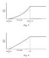
- FIG. 5is a graph showing an exemplary relationship between the amount of open area of the reed valve and pressure at either side of the reed valve.
- FIG. 6is a graph showing an exemplary relationship between the amount of open area of a conventional ball-type check valve and pressure acting on the valve.
- the present disclosurerelates generally to a method and system for treating an ocular condition. It relates more specifically to an adjustable flow control valve in series with a reed valve to control the flow rate of aqueous humor through the system in a manner that reduces the occurrence of excessive pressure drops and high frequency oscillatory pressures even during high pressure drop conditions. In turn, this reduces the chance of pressure overshoots resulting in a more stable control of IOP.
- the reed valvemay serve two functions. First, it operates as a check valve to prevent backward flow. Second, unlike conventional check valves such as a ball valve, the reed valve may be designed to provide stabilizing flow control even during higher drop pressure conditions.
- the reed valves disclosed hereinmay stabilize drainage flow during high pressure conditions by maintaining flow at a satisfactory rate while still permitting therapeutic fluid flow at low pressure conditions. This may alleviate the occurrence of high flow pressure drops across the adjustable valve membrane that can occur immediately after implantation of a glaucoma drainage device, resulting in a stable, more controlled drainage from the anterior chamber, resulting in a better patient outcome.
- the reed valveopens and closes due to the changing pressure across the surface of the flap.
- a hard stopcan be provided to control the maximum flow through the system.
- the cracking pressure and the rate of openingare defined by the stress-strain curve of the material of the reed valve used and the net pressure difference across the flap. Sophisticated flaps can be created for different gains at different open positions so as to avoid resonance problems.
- the range of cracking pressure of the reed valvecan be anywhere between 3 mmHg to 100 mmHg.
- FIG. 2shows an exemplary ocular implant 102 disposed on an eye according to one exemplary aspect of the present disclosure.
- the implant 102includes a body referred to herein as a plate 104 and a drainage tube 106 that extends from the plate 104 .
- the plate 104is arranged to carry various components of an IOP control system, and may include a valve, pump, transducers or sensors, a processing system and memory, drug delivery components, a power source or other components that may be used to either control the implant 102 or otherwise treat ocular conditions.
- the plate 104is configured to fit at least partially within the subconjunctival space and is sized for example within a range between about 15 mm ⁇ 12 mm to about 30 mm ⁇ 15 mm and has a thickness less than about 2 mm thick and preferably less than about 1 mm thick.
- the plate 104may be formed to the radius of the eye globe (about 0.5 inches). It may be rigid and preformed with a curvature suitable to substantially conform to the globe or it may be flexible to conform to the globe. Some embodiments are small enough that conforming to the globe provides little benefit in comfort or implantation technique.
- the above dimensionsare exemplary only, and other sizes and arrangements are contemplated.
- the plate 104When implanted, the plate 104 may be located in the subconjunctival pocket between the conjunctiva and sclera. It may be generally located on an ocular quadrant commonly used for conventional glaucoma drainage devices with plates; that is, it may be centered such that it is equidistant from the neighboring ocular muscles that define the ocular quadrant chosen for implantation.
- the drainage tube 106is sized to bridge the anterior chamber and the plate 104 in the subconjunctival pocket to provide an auxiliary flow path for aqueous humor, bypassing the flow-resistive conventional pathway through the trabecular meshwork and shunting aqueous humor directly to a drainage site.
- the drainage tube 106is a single tube having a single lumen.
- Other embodimentsinclude a plurality of drainage tubes or a plurality of lumens cooperating together to permit fluid to flow through the implant 102 .
- the drainage tube 106is sized to extend from the plate 104 to the anterior chamber of the eye, as shown in FIG. 2 .
- Aqueous humormay drain through the drainage tube from the anterior chamber to and out of the plate 104 to alleviate elevated intraocular pressure conditions.
- FIG. 3shows a stylized cross-sectional view of a portion of the plate 104 .
- the plate 104includes a valve membrane valve system 118 formed of a housing 120 with an entrance port 122 and an exit port 124 , a flow control system 126 with a flexible membrane 127 in the housing 120 , and a fluid flow passageway 128 extending between the entrance port 122 and the exit port 124 .
- the entrance port 122connects to the drainage tube 106 and is configured to receive aqueous flowing from the drainage tube 106 .
- the exit port 124permits fluid to exit the housing 120 for release at a drainage site or for further regulation.
- the passageway 128includes a first portion 134 extending through a boss 136 that is arranged to cooperate with the flow control system 126 to control drainage fluid flow, and a second, larger portion 140 configured in the embodiment shown as a chamber adjacent the boss 136 , that less actively impacts the flow through the plate 106 .
- the first portion 134 of the fluid flow passageway 128is formed to be substantially perpendicular to the general plane of the flexible membrane 127 , and the upper surface of the boss 136 is arranged to be substantially parallel to the general plane of the flexible membrane 127 . As such, flow through the first portion 134 is directed in the direction of and directly at the flexible membrane 127 .
- the flexible membrane 127 in this exemplary embodimentcan more easily displace only slightly, but still provide a significant modification in the drainage flow. This occurs because the flexible membrane 127 may act in some respects as a cap on the first portion 134 of the fluid flow passageway.
- the flexible membrane 127is arranged to cover the entire upper surface of the boss 136 , and may even stretch to extend at least partially along the sides of the boss 136 adjacent the edge between the top of the boss 136 and the sides. Accordingly, in such embodiments, the flexible membrane 127 may largely limit or entirely cut off flow through the implant 102 .
- the second portion 140 of the fluid flow passageway 128is configured in some respects as a chamber adjacent the boss 136 , having a much larger volume. Accordingly, although the second portion 140 of the passageway 128 extends along a portion of the flexible membrane 127 , displacement of the membrane does not have as significant an effect on the drainage fluid flow. Accordingly, in this embodiment, the drainage fluid flow is controlled primarily at the region along the top of the boss 136 , which in this embodiment is disposed at the central part of the membrane 127 .
- the fluid flow passageway 128include flexible membrane material that may displace to affect fluid flow through the passageway from more than one direction.
- the flexible membrane 127acts as a toroid or sphincter, with the passageway extending through the hollow center or orifice.
- the flexible membrane 127is disposed on two sides of the passageway. In some of these examples the sides are on opposing sides of the passageway. Some of these embodiments may have two or more separate flexible membranes that cooperate to limit the cross-sectional area of the fluid flow passageway 128 .
- the flexible membrane 127may be formed of an elastically deformable elastomeric including without limitation, materials such as a silicone, silicon nitride, silicone elastomeric, polyimide, parylene and others.
- the flexible membraneis secured to the housing 120 at its edges.
- the flexible membrane 127is a circular material secured at its periphery to the housing 120 .
- the housing 120 and flexible membrane 127are formed so that the membrane has a non-circular shape, including oval, substantially rectangular, or square, for example. Other shapes are also contemplated.
- the ocular implant 102in addition to the drainage tube 106 extending from the inlet 122 of the plate 104 , the ocular implant 102 includes a drainage element 146 that is intended to release fluid to a drainage site after passing through the plate 104 and out of the exit port 124 . While shown in FIG. 3 as a drainage tube, the drainage element 146 may be nothing more than the exit port 124 from the implant plate 104 or may be some other drainage passage.
- the drainage element 146includes a reed valve 160 therein that cooperates to stabilize flow of aqueous humor through the implant 102 .
- the reed valve 160is disposed downstream of the membrane valve and in this embodiment, serves dual purposes. First, the reed valve 160 operates as a one-way check valve that permits drainage from the anterior chamber, past the membrane valve, and towards the drainage site. Second, the reed valve 160 regulates drainage flow to provide a more stable flow rate for consistent drainage in a manner not achieved by conventional check valves, including ball-type check valves. These advantages will be discussed in greater detail with reference to FIG. 4 .
- FIG. 4is an enlarged portion of FIG. 3 showing the reed valve 160 in greater detail.
- the drainage element 146is a drainage tube, but the drainage element can be an element downstream of the membrane valve 118 .
- the drainage elementmay be a passage within the housing 120 or may be in a flexible tube or other location.
- the reed valve 160in this instance is disposed in the drainage element 146 and comprises a reed 162 and a hard stop 164 .
- the reed 162includes an attachment end 166 and a cantilevered end 168 .
- the attachment end 166is fixed in place in the drainage element 146
- the cantilevered end 168is free to move in one direction away from the wall of the drainage element 146 to allow fluid to pass, and arranged to engage the wall of the drainage element 146 to prevent backflow.
- the reed 162is formed of a flexible material and is configured to deflect, where the amount of deflection is dependent on the pressure of the fluid.
- the reed 162deflects based on differentials between upstream pressure, representative of the anterior chamber pressure, and downstream pressure behind the reed valve, representative of pressure at the drainage site.
- the reed valve 160may have a cracking pressure set at a desired pressure, such as about 3 mmHg. Therefore, when the upstream pressure is greater than the downstream by more than the cracking pressure, the reed valve 160 will begin to open to relieve pressure.
- the reed valveis configured and disposed to have a cracking pressure between about 0.25 mmHg and 8 mmHg.
- the reed 162is formed of a flexible polymer material.
- the reedis formed of the same material as the flexible membrane. It may be formed of any suitable material, including, for example without limitation, materials such as a silicone, silicon nitride, silicone elastomeric, polyimide, parylene and others.
- the stiffness, material, and dimensions of the reed 162can be selected to provide a desired gain in response to pressure. Accordingly, the reed 162 may be selected or designed to deflect a particular amount to permit a particular fluid flow based on the pressure amounts.
- the cross-sectional dimensions or material of the reed 162changes along the length of the reed.
- the reedmay be controlled to have a flexible distal end portion that deflects during relatively small pressure differentials and a less flexible central portion that deflects in response to relatively higher pressure differential flows.
- some exemplary reedsare formed with a tapering body so that the reed has a region of higher stiffness and a region of lower stiffness.
- Other embodimentsinclude stepped increasing and/or decreasing cross-sections to achieve the desired deflection under the appropriate loads.
- Some embodimentshave substantially uniform thicknesses along the length, as shown in FIG. 4 .
- the transverse segment 170includes a transverse segment length and the angled segment 174 includes an angled segment length that are selected to provide a desired rigidity and, in cooperation with the membrane 162 , to provide a balanced stability during flow conditions.
- the hard stop 164is disposed adjacent the reed 162 and is configured to mechanically interfere with the reed deflection to limit the total gain or size of the flow passageway through the reed valve 160 . In this example, the hard stop 164 extends more than half the distance across the drainage element.
- the hard stop 164is disposed to limit the reed deflection to an amount that will limit the flow rate through the valve to prevent overly fast pressure drops in high pressure scenarios.
- the reed valve 160may be configured with a deflection resistance that is more controllable than a conventional check valve to prevent excessive gain and thereby stabilize flow during high and low pressure differentials.
- the hard stop 164is located in a manner to affect or limit the deflection of the reed to a particular pressure in the range of 8 mmHg to 15 mmHg.
- FIG. 4also shows the fluid flow pattern as a result of the reed valve 160 .
- the reed valvedirects fluid to flow along a side, rather than centrally through the valve. This creates turbulence in the flow downstream of the reed 162 .
- the fluid flow along the wallcreates an opposing eddy.
- the eddyis created substantially on the downstream side of the hard stop 164 . Therefore, its effect on the reed 162 is minimized, providing a greater consistency over a variety of differential flow rates and pressure differentials.
- Membrane valves in high pressure differential scenarioscan flutter, decreasing stability and disrupting smooth or continuous flow from the anterior chamber toward the drainage site.
- the reed valve 160with its deflectable reed 162 and the hard stop 164 that limits the displacement of the reed, may stabilize the flow to provide a smooth transition.
- the reed valve 160can maintain a backpressure in the system that provides stability in the system during dynamic draining. It does this by creating a backpressure in the system at the membrane valve, thereby controlling flow past the membrane valve. Because of the backpressure, the membrane in the valve is more stable, providing a smoother, more consistent flow. This may provide greater control and flow stability than conventional check valves, such as ball-type check valves.
- FIG. 5shows an exemplary plot displaying the relationship between the gain or cross-sectional area of the reed valve in response to pressure.
- the gain or open areais represented by the y-axis and the fluid pressure through the valve is represented along the x-axis.
- the reed valvewill begin to open. This is identified as the cracking pressure on the graph in FIG. 5 .
- the reed 162will continue to deflect, and the open area will increase as pressure increases.
- the curvehas a concave shape represented by the exponentially increasing resistance to deflection of the reed 162 .
- the reedcomes into contact with the hard stop 162 .
- the reed valveis prevented from opening further, and even under pressure increases, the gain or open area of the valve may be maintained relatively consistent.
- FIG. 6shows the relationship between the amount of open area of a conventional ball-type check valve and pressure acting on the valve.
- the conventional ball-type check valvehas a consistent or relatively linear change in area as pressure increases.
- the reed valvehas different tendencies than a ball-type check valve because it enables control of the gain, can be used to control flow at low pressure deviations and at higher pressure deviations.
- the advantagearises because the reed valve can create backpressure that stabilizes flow in even high pressure differential conditions, such as those immediately following surgery. Through the use of the hard stop 164 , excessive pressure drops may be reduced, resulting in a more satisfactory implant and better patient outcome.
- the surgeonselects the reed valve 160 to be associated with an implant at the time of implantation to particularly tune the valve to the patient.
- the surgeonmay be provided with multiple reed valves and may attach the reed valve to the plate 104 depending on patient need.
- the surgeonmay be provided with a plurality of reed valves, where each reed valve differs from each other.
- one reed valvemay be configured to have a cracking pressure of 2 mmHg and may have a hard-stop condition between 8 and 10 mmHg.
- a different reed valvemay have a cracking pressure of 2 mmHg and may have a hard-stop condition between 10 and 12 mmHg.
- a third reed valvemay have a have a cracking pressure of 2 mmHg and may have a hard-stop condition between 12 and 14 mmHg.
- a different reed valvemay have a cracking pressure at 3 mmHg and may have a hard-stop condition between 8 and 10 mmHg.
- the plurality of reed valvescould be configured with other ranges and hard stop conditions.
- the reed valve system disclosed hereinprovides a flow control profile not obtainable with standard ball-type check valves and can be used in high pressure situations to provide stabilizing back pressure that reduces excessive pressure drops to possibly achieve better clinical results while still performing properly during low pressure situations.
- the reed valvecooperates with the membrane valve to balance the flow through the valve to provide a smooth, controlled drainage without loss of valve control.
- the reed valveis configured to provide a back pressure to the membrane valve that is maintained at a desired level even during pressure variations. This may be designed not only in closed valve situations, such as by the cracking pressure, but also during open conditions, when pressure is flowing.
- an additional ball-type check valveis used downstream of the reed valve.
- the benefits of stabilizing flow through the membranemay still be obtained while the ball-type check valve may be used to prevent reverse directional flow.
- the back-flow prevention characteristics of the ball-type check valvewould be redundant, further decreasing the risk of backflow of fluid from the drainage location to the anterior chamber of the eye.
Landscapes
- Engineering & Computer Science (AREA)
- General Engineering & Computer Science (AREA)
- Health & Medical Sciences (AREA)
- Mechanical Engineering (AREA)
- Ophthalmology & Optometry (AREA)
- Life Sciences & Earth Sciences (AREA)
- Heart & Thoracic Surgery (AREA)
- Vascular Medicine (AREA)
- Biomedical Technology (AREA)
- Animal Behavior & Ethology (AREA)
- General Health & Medical Sciences (AREA)
- Public Health (AREA)
- Veterinary Medicine (AREA)
- Nuclear Medicine, Radiotherapy & Molecular Imaging (AREA)
- Surgery (AREA)
- Prostheses (AREA)
- External Artificial Organs (AREA)
Abstract
Description
Claims (17)
Priority Applications (2)
| Application Number | Priority Date | Filing Date | Title |
|---|---|---|---|
| US13/433,557US8998838B2 (en) | 2012-03-29 | 2012-03-29 | Adjustable valve for IOP control with reed valve |
| PCT/US2013/033717WO2013148581A1 (en) | 2012-03-29 | 2013-03-25 | Adjustable valve for iop control with reed valve |
Applications Claiming Priority (1)
| Application Number | Priority Date | Filing Date | Title |
|---|---|---|---|
| US13/433,557US8998838B2 (en) | 2012-03-29 | 2012-03-29 | Adjustable valve for IOP control with reed valve |
Publications (2)
| Publication Number | Publication Date |
|---|---|
| US20130261530A1 US20130261530A1 (en) | 2013-10-03 |
| US8998838B2true US8998838B2 (en) | 2015-04-07 |
Family
ID=48045802
Family Applications (1)
| Application Number | Title | Priority Date | Filing Date |
|---|---|---|---|
| US13/433,557Active2033-06-10US8998838B2 (en) | 2012-03-29 | 2012-03-29 | Adjustable valve for IOP control with reed valve |
Country Status (2)
| Country | Link |
|---|---|
| US (1) | US8998838B2 (en) |
| WO (1) | WO2013148581A1 (en) |
Cited By (21)
| Publication number | Priority date | Publication date | Assignee | Title |
|---|---|---|---|---|
| US20160338619A1 (en)* | 2014-01-24 | 2016-11-24 | Aerocrine Ab | Miniaturized fluid flow regulating device |
| US9655778B2 (en) | 2015-07-13 | 2017-05-23 | Thomas D. Tyler | Position responsive flow adjusting implantable device and method |
| US9730638B2 (en) | 2013-03-13 | 2017-08-15 | Glaukos Corporation | Intraocular physiological sensor |
| US10271989B2 (en) | 2012-03-26 | 2019-04-30 | Glaukos Corporation | System and method for delivering multiple ocular implants |
| US10285856B2 (en) | 2001-08-28 | 2019-05-14 | Glaukos Corporation | Implant delivery system and methods thereof for treating ocular disorders |
| US10342702B2 (en) | 2014-08-29 | 2019-07-09 | Camras Vision Inc. | Apparatus and method for reducing intraocular pressure |
| US10369050B2 (en) | 2014-08-29 | 2019-08-06 | Camras Vision Inc. | Device and method for reducing intraocular pressure |
| US10406029B2 (en) | 2001-04-07 | 2019-09-10 | Glaukos Corporation | Ocular system with anchoring implant and therapeutic agent |
| US10485701B2 (en) | 2002-04-08 | 2019-11-26 | Glaukos Corporation | Devices and methods for glaucoma treatment |
| US10485702B2 (en) | 2000-04-14 | 2019-11-26 | Glaukos Corporation | System and method for treating an ocular disorder |
| US10492950B2 (en) | 1999-04-26 | 2019-12-03 | Glaukos Corporation | Shunt device and method for treating ocular disorders |
| US10517759B2 (en) | 2013-03-15 | 2019-12-31 | Glaukos Corporation | Glaucoma stent and methods thereof for glaucoma treatment |
| US10524958B2 (en) | 2015-09-30 | 2020-01-07 | Alievio, Inc. | Method and apparatus for reducing intraocular pressure |
| US10828473B2 (en) | 2001-04-07 | 2020-11-10 | Glaukos Corporation | Ocular implant delivery system and methods thereof |
| US10828195B2 (en) | 2006-11-10 | 2020-11-10 | Glaukos Corporation | Uveoscleral shunt and methods for implanting same |
| US10959941B2 (en) | 2014-05-29 | 2021-03-30 | Glaukos Corporation | Implants with controlled drug delivery features and methods of using same |
| US11116625B2 (en) | 2017-09-28 | 2021-09-14 | Glaukos Corporation | Apparatus and method for controlling placement of intraocular implants |
| US11197779B2 (en) | 2015-08-14 | 2021-12-14 | Ivantis, Inc. | Ocular implant with pressure sensor and delivery system |
| US11363951B2 (en) | 2011-09-13 | 2022-06-21 | Glaukos Corporation | Intraocular physiological sensor |
| US11925578B2 (en) | 2015-09-02 | 2024-03-12 | Glaukos Corporation | Drug delivery implants with bi-directional delivery capacity |
| US20240123161A1 (en)* | 2019-11-08 | 2024-04-18 | Stryker Corporation | Fluid management systems and methods |
Families Citing this family (5)
| Publication number | Priority date | Publication date | Assignee | Title |
|---|---|---|---|---|
| US8956320B2 (en)* | 2012-08-28 | 2015-02-17 | Alcon Research, Ltd. | Capillary valve |
| EP3669836B1 (en)* | 2016-06-03 | 2021-08-04 | New World Medical, Inc. | Intraocular drainage device |
| WO2018156687A1 (en)* | 2017-02-22 | 2018-08-30 | Board Of Regents, The University Of Texas System | A novel flexible microfluidic meshwork for glaucoma surgery |
| KR20250069675A (en) | 2018-08-09 | 2025-05-19 | 밸런스 오프탈믹스, 인크. | Apparatus and methods to adjust ocular blood flow |
| US11786401B2 (en) | 2019-03-18 | 2023-10-17 | Verily Life Sciences Llc | Peristaltic micropump assemblies and associated devices, systems, and methods |
Citations (90)
| Publication number | Priority date | Publication date | Assignee | Title |
|---|---|---|---|---|
| US4089329A (en) | 1976-03-18 | 1978-05-16 | University Of Utah Research Institute | Noninvasive, continuous intraocular pressure monitor |
| US4206762A (en) | 1976-06-21 | 1980-06-10 | Cosman Eric R | Telemetric differential pressure sensing method |
| US4457757A (en) | 1981-07-20 | 1984-07-03 | Molteno Anthony C B | Device for draining aqueous humour |
| US4656827A (en) | 1984-10-17 | 1987-04-14 | Societe Nationale d'Etude et de Construction de Meteur d'Aviation-"S.N.E. C.M.A." | Fuel metering system for a gas turbine engine |
| US4750901A (en) | 1986-03-07 | 1988-06-14 | Molteno Anthony C B | Implant for drainage of aqueous humour |
| US4922913A (en) | 1987-11-12 | 1990-05-08 | Waters Jr George E | Intraocular pressure sensor |
| US5005577A (en) | 1988-08-23 | 1991-04-09 | Frenkel Ronald E P | Intraocular lens pressure monitoring device |
| US5071408A (en)* | 1988-10-07 | 1991-12-10 | Ahmed Abdul Mateen | Medical valve |
| US5178604A (en) | 1990-05-31 | 1993-01-12 | Iovision, Inc. | Glaucoma implant |
| US5179953A (en) | 1991-08-27 | 1993-01-19 | Jermik Systems, Ltd. | Portable diurnal intraocular pressure recording system |
| WO1993003665A1 (en) | 1991-08-27 | 1993-03-04 | Jermik Systems, Ltd. | Portable intraocular pressure measurement method and apparatus |
| US5326345A (en)* | 1991-08-14 | 1994-07-05 | Price Jr Francis W | Eye filtration prostheses |
| US5397300A (en) | 1990-05-31 | 1995-03-14 | Iovision, Inc. | Glaucoma implant |
| US5476445A (en) | 1990-05-31 | 1995-12-19 | Iovision, Inc. | Glaucoma implant with a temporary flow restricting seal |
| DE4438201A1 (en) | 1994-10-26 | 1996-05-02 | Gerhard Heinrich Dr In Steeger | Intraocular fluid pressure stabilisation device for treating glaucoma |
| US5655898A (en)* | 1995-11-14 | 1997-08-12 | Sanden Corporation | Reed valve arrangement for a reciprocating compressor |
| WO1998003665A1 (en) | 1996-07-22 | 1998-01-29 | Incyte Pharmaceuticals, Inc. | Human kallikrein |
| US5910110A (en) | 1995-06-07 | 1999-06-08 | Mentor Ophthalmics, Inc. | Controlling pressure in the eye during surgery |
| WO1999038470A2 (en) | 1998-01-29 | 1999-08-05 | David Pyam Soltanpour | Method and apparatus for controlling intraocular pressure |
| US6007511A (en) | 1991-05-08 | 1999-12-28 | Prywes; Arnold S. | Shunt valve and therapeutic delivery system for treatment of glaucoma and methods and apparatus for its installation |
| US6047698A (en)* | 1998-08-20 | 2000-04-11 | Moldex-Metric, Inc. | Unidirectional fluid valve |
| US20010000527A1 (en) | 1997-11-20 | 2001-04-26 | Optonol Ltd. | Flow regulating implant, method of manufacture, and delivery device |
| WO2001094784A1 (en) | 2000-06-05 | 2001-12-13 | Mohsen Shahinpoor | Synthetic muscle based diaphragm pump apparatuses |
| US20020019607A1 (en) | 1998-05-21 | 2002-02-14 | Hai Bui | Constant ocular pressure active infusion system |
| US20020049374A1 (en) | 1996-09-04 | 2002-04-25 | Abreu Marcio Marc | Method and apparatus for signal transmission and detection using a contact device |
| US20020099359A1 (en) | 2001-01-09 | 2002-07-25 | Santini John T. | Flexible microchip devices for ophthalmic and other applications |
| US6447449B1 (en) | 2000-08-21 | 2002-09-10 | Cleveland Clinic Foundation | System for measuring intraocular pressure of an eye and a MEM sensor for use therewith |
| US6453940B1 (en)* | 1999-12-20 | 2002-09-24 | Federal-Mogul Corporation | Insert bonded combination valve |
| US20020143284A1 (en) | 2001-04-03 | 2002-10-03 | Hosheng Tu | Drug-releasing trabecular implant for glaucoma treatment |
| US6468283B1 (en) | 1995-05-14 | 2002-10-22 | Optonol, Ltd. | Method of regulating pressure with an intraocular implant |
| US20020193674A1 (en) | 2000-08-21 | 2002-12-19 | The Cleveland Clinic Foundation | Measurement system including a sensor mounted in a contact lens |
| WO2003001991A1 (en) | 2001-06-29 | 2003-01-09 | Ecole Polytechnique Federale De Lausanne (Epfl) | Intraocular pressure recording system |
| US20030078487A1 (en) | 2001-08-09 | 2003-04-24 | Jeffries Robert E. | Ocular pressure measuring device |
| US6579235B1 (en) | 1999-11-01 | 2003-06-17 | The Johns Hopkins University | Method for monitoring intraocular pressure using a passive intraocular pressure sensor and patient worn monitoring recorder |
| US20030225318A1 (en) | 2002-05-31 | 2003-12-04 | Valentino Montegrande | Intraocular pressure sensor |
| US6682500B2 (en) | 1998-01-29 | 2004-01-27 | David Soltanpour | Synthetic muscle based diaphragm pump apparatuses |
| US20040059248A1 (en) | 2001-01-17 | 2004-03-25 | Arthur Messner | Implant for determining intra-ocular pressure |
| US6712764B2 (en) | 1999-02-08 | 2004-03-30 | Robert E. Jeffries | Intraocular pressure monitoring/measuring apparatus and method |
| US20040073137A1 (en) | 2002-08-27 | 2004-04-15 | Board Of Trustees Of Michigan State University | Implantable microscale pressure sensor system for pressure monitoring and management |
| US20040111050A1 (en) | 2000-04-14 | 2004-06-10 | Gregory Smedley | Implantable ocular pump to reduce intraocular pressure |
| US20040116794A1 (en) | 2002-10-16 | 2004-06-17 | Wolfgang Fink | Optically powered and optically data-transmitting wireless intraocular pressure sensor device |
| US20040186367A1 (en) | 2001-05-11 | 2004-09-23 | Fresco Bernard B. | Dual tonometer |
| US20040254438A1 (en) | 2003-01-09 | 2004-12-16 | The Regents Of The University Of California | Implantable devices and methods for measuring intraocular, subconjunctival or subdermal pressure and/or analyte concentration |
| US20040254517A1 (en) | 2003-02-18 | 2004-12-16 | Hugo Quiroz-Mercado | Methods and devices for draining fluids and lowering intraocular pressure |
| US20050159660A1 (en) | 2002-05-31 | 2005-07-21 | Valentino Montegrande | Intraocular pressure sensor |
| US20050175494A1 (en)* | 2003-03-05 | 2005-08-11 | Daikin Industries, Ltd. | Compressor |
| US6939299B1 (en) | 1999-12-13 | 2005-09-06 | Kurt Petersen | Implantable continuous intraocular pressure sensor |
| US20050271704A1 (en) | 2002-04-08 | 2005-12-08 | Hosheng Tu | Injectable glaucoma implants with multiple openings |
| US20050273033A1 (en) | 2002-05-29 | 2005-12-08 | Grahn Bruce H | Shunt and method treatment of glaucoma |
| US20060131350A1 (en) | 2004-12-22 | 2006-06-22 | Schechter Alan M | Apparatus for dispensing pressurized contents |
| US20070019156A1 (en) | 2005-07-15 | 2007-01-25 | California Institute Of Technology | Optomechanical and digital ocular sensor reader systems |
| US20070032757A1 (en) | 2003-09-09 | 2007-02-08 | Medow Joshua E | Medical shunt/valve for regulation of bodily fluids |
| US20070106199A1 (en) | 1998-01-29 | 2007-05-10 | Daniel Krivoy | Implantable pump apparatuses |
| US20070109117A1 (en) | 2005-11-14 | 2007-05-17 | Edwards Lifesciences Corporation | Wireless communication protocol for a medical sensor system |
| US20070123767A1 (en) | 2002-05-31 | 2007-05-31 | Valentino Montegrande | Intraocular pressure sensor and method of use |
| US7252006B2 (en) | 2004-06-07 | 2007-08-07 | California Institute Of Technology | Implantable mechanical pressure sensor and method of manufacturing the same |
| US20070212397A1 (en) | 2005-09-15 | 2007-09-13 | Roth Daniel B | Pharmaceutical delivery device and method for providing ocular treatment |
| WO2007127305A2 (en) | 2006-04-26 | 2007-11-08 | Eastern Virginia Medical School | Systems and methods for monitoring and controlling internal pressure of an eye or body part |
| WO2007136993A1 (en) | 2006-05-17 | 2007-11-29 | Mayo Foundation For Medical Education And Research | Monitoring intraocular pressure |
| US20080015421A1 (en) | 2000-10-16 | 2008-01-17 | Remon Medical Technologies, Ltd. | Barometric pressure correction based on remote sources of information |
| US20080066815A1 (en)* | 2006-09-19 | 2008-03-20 | Anderson Lance E | One-way elastomer valve |
| US20080077127A1 (en) | 2006-09-27 | 2008-03-27 | Gao Shawn X | Intraocular pressure control |
| WO2008061043A2 (en) | 2006-11-10 | 2008-05-22 | Glaukos Corporation | Uveoscleral shunt and methods for implanting same |
| US20080129486A1 (en) | 2005-04-26 | 2008-06-05 | Joel Jeckelmann | Energy-Optimised Data Transmission for a Medical Appliance |
| WO2008084350A2 (en) | 2007-01-08 | 2008-07-17 | Consejo Nacional De Investigaciones Científicas Y Técnicas (Conicet) | Implantable ocular microapparatus to ameliorate glaucoma or an ocular overpressure causing disease |
| US7409863B2 (en) | 2004-10-05 | 2008-08-12 | Sensata Technologies Maryland, Inc. | Pressure sensor |
| WO2009026499A1 (en) | 2007-08-23 | 2009-02-26 | Purdue Research Foundation | Intra-occular pressure sensor |
| WO2009049686A1 (en) | 2007-10-19 | 2009-04-23 | Sensimed Ag | Intraocular pressure monitoring device |
| US20090143713A1 (en) | 2007-11-30 | 2009-06-04 | Jacques Van Dam | Biliary Shunts, Delivery Systems, Methods of Using the Same and Kits Therefor |
| US20090159826A1 (en)* | 2004-11-19 | 2009-06-25 | Geoff Wayne Poulton | Valve |
| WO2009081031A2 (en) | 2007-12-18 | 2009-07-02 | Alain Telandro | System for measuring intraocular pressure |
| US20090227933A1 (en) | 2003-02-18 | 2009-09-10 | S.K. Pharmaceuticals | Optic nerve implants |
| US7612328B2 (en) | 2005-07-11 | 2009-11-03 | Iee International Electronics & Engineering S.A. | Foil-type pressure sensor |
| US20090277206A1 (en)* | 2008-05-12 | 2009-11-12 | Bryce Laufenberg | A/C drain line device |
| US20090312742A1 (en) | 2008-05-08 | 2009-12-17 | Changlin Pang | Drug-delivery pumps and methods of manufacture |
| US20100010416A1 (en) | 2006-01-17 | 2010-01-14 | Juan Jr Eugene De | Glaucoma treatment device |
| US20100121348A1 (en) | 2008-11-12 | 2010-05-13 | Ross Creek Medical | Insertion tool for knotless suture anchor for soft tissue repair and method of use |
| WO2010093945A2 (en) | 2009-02-13 | 2010-08-19 | Glaukos Corporation | Uveoscleral drug delivery implant and methods for implanting the same |
| US20100253167A1 (en) | 2007-07-17 | 2010-10-07 | Sheppard & Charnley Limited | Electric motor/generator assembly |
| WO2010129446A1 (en) | 2009-05-04 | 2010-11-11 | Alcon Research, Ltd. | Intraocular pressure sensor |
| US20110046536A1 (en) | 2009-08-20 | 2011-02-24 | Grieshaber Ophthalmic Research Foundation | Method and device for the treatment of glaucoma |
| WO2011034740A1 (en) | 2009-09-21 | 2011-03-24 | Alcon Research, Ltd. | Power saving glaucoma drainage device |
| US20110071458A1 (en)* | 2009-09-21 | 2011-03-24 | Alcon Research, Ltd. | Glaucoma Drainage Device with Pump |
| US20110071454A1 (en) | 2009-09-21 | 2011-03-24 | Alcon Research, Ltd. | Power Generator For Glaucoma Drainage Device |
| WO2011034727A1 (en) | 2009-09-21 | 2011-03-24 | Alcon Research, Ltd. | Intraocular pressure sensor with external pressure compensation |
| WO2011035218A1 (en) | 2009-09-21 | 2011-03-24 | Alcon Research, Ltd. | Lumen clearing valve for glaucoma drainage device |
| US20110211974A1 (en)* | 2010-03-01 | 2011-09-01 | William Anthony Harper | Curved pliant film valves |
| US20110248671A1 (en) | 2010-04-08 | 2011-10-13 | Alcon Research, Ltd. | Power System Implantable in Eye |
| US20120121449A1 (en)* | 2009-04-28 | 2012-05-17 | Rolf Prettl | Check valve |
| US20120177510A1 (en)* | 2011-01-07 | 2012-07-12 | XCOR Aerospace, Inc. | High-speed check valve suitable for cryogens and high reverse pressure |
- 2012
- 2012-03-29USUS13/433,557patent/US8998838B2/enactiveActive
- 2013
- 2013-03-25WOPCT/US2013/033717patent/WO2013148581A1/enactiveApplication Filing
Patent Citations (115)
| Publication number | Priority date | Publication date | Assignee | Title |
|---|---|---|---|---|
| US4089329A (en) | 1976-03-18 | 1978-05-16 | University Of Utah Research Institute | Noninvasive, continuous intraocular pressure monitor |
| US4206762A (en) | 1976-06-21 | 1980-06-10 | Cosman Eric R | Telemetric differential pressure sensing method |
| US4457757A (en) | 1981-07-20 | 1984-07-03 | Molteno Anthony C B | Device for draining aqueous humour |
| US4656827A (en) | 1984-10-17 | 1987-04-14 | Societe Nationale d'Etude et de Construction de Meteur d'Aviation-"S.N.E. C.M.A." | Fuel metering system for a gas turbine engine |
| US4750901A (en) | 1986-03-07 | 1988-06-14 | Molteno Anthony C B | Implant for drainage of aqueous humour |
| US4922913A (en) | 1987-11-12 | 1990-05-08 | Waters Jr George E | Intraocular pressure sensor |
| US5005577A (en) | 1988-08-23 | 1991-04-09 | Frenkel Ronald E P | Intraocular lens pressure monitoring device |
| US5071408A (en)* | 1988-10-07 | 1991-12-10 | Ahmed Abdul Mateen | Medical valve |
| US5558629A (en) | 1990-05-31 | 1996-09-24 | Iovision, Inc. | Glaucoma implant |
| US5397300A (en) | 1990-05-31 | 1995-03-14 | Iovision, Inc. | Glaucoma implant |
| US5476445A (en) | 1990-05-31 | 1995-12-19 | Iovision, Inc. | Glaucoma implant with a temporary flow restricting seal |
| US5178604A (en) | 1990-05-31 | 1993-01-12 | Iovision, Inc. | Glaucoma implant |
| US6007511A (en) | 1991-05-08 | 1999-12-28 | Prywes; Arnold S. | Shunt valve and therapeutic delivery system for treatment of glaucoma and methods and apparatus for its installation |
| US5326345A (en)* | 1991-08-14 | 1994-07-05 | Price Jr Francis W | Eye filtration prostheses |
| US5179953A (en) | 1991-08-27 | 1993-01-19 | Jermik Systems, Ltd. | Portable diurnal intraocular pressure recording system |
| WO1993003665A1 (en) | 1991-08-27 | 1993-03-04 | Jermik Systems, Ltd. | Portable intraocular pressure measurement method and apparatus |
| DE4438201A1 (en) | 1994-10-26 | 1996-05-02 | Gerhard Heinrich Dr In Steeger | Intraocular fluid pressure stabilisation device for treating glaucoma |
| US6468283B1 (en) | 1995-05-14 | 2002-10-22 | Optonol, Ltd. | Method of regulating pressure with an intraocular implant |
| US5910110A (en) | 1995-06-07 | 1999-06-08 | Mentor Ophthalmics, Inc. | Controlling pressure in the eye during surgery |
| US5655898A (en)* | 1995-11-14 | 1997-08-12 | Sanden Corporation | Reed valve arrangement for a reciprocating compressor |
| WO1998003665A1 (en) | 1996-07-22 | 1998-01-29 | Incyte Pharmaceuticals, Inc. | Human kallikrein |
| US20020049374A1 (en) | 1996-09-04 | 2002-04-25 | Abreu Marcio Marc | Method and apparatus for signal transmission and detection using a contact device |
| US20080125691A1 (en) | 1997-11-20 | 2008-05-29 | Optonol Ltd. | Flow regulating implants |
| US20010000527A1 (en) | 1997-11-20 | 2001-04-26 | Optonol Ltd. | Flow regulating implant, method of manufacture, and delivery device |
| WO1999038470A2 (en) | 1998-01-29 | 1999-08-05 | David Pyam Soltanpour | Method and apparatus for controlling intraocular pressure |
| US6682500B2 (en) | 1998-01-29 | 2004-01-27 | David Soltanpour | Synthetic muscle based diaphragm pump apparatuses |
| US20070106199A1 (en) | 1998-01-29 | 2007-05-10 | Daniel Krivoy | Implantable pump apparatuses |
| US6589198B1 (en)* | 1998-01-29 | 2003-07-08 | David Soltanpour | Implantable micro-pump assembly |
| WO1999038470A3 (en) | 1998-01-29 | 1999-10-07 | David Pyam Soltanpour | Method and apparatus for controlling intraocular pressure |
| US20020019607A1 (en) | 1998-05-21 | 2002-02-14 | Hai Bui | Constant ocular pressure active infusion system |
| US6047698A (en)* | 1998-08-20 | 2000-04-11 | Moldex-Metric, Inc. | Unidirectional fluid valve |
| US6712764B2 (en) | 1999-02-08 | 2004-03-30 | Robert E. Jeffries | Intraocular pressure monitoring/measuring apparatus and method |
| US6579235B1 (en) | 1999-11-01 | 2003-06-17 | The Johns Hopkins University | Method for monitoring intraocular pressure using a passive intraocular pressure sensor and patient worn monitoring recorder |
| US6939299B1 (en) | 1999-12-13 | 2005-09-06 | Kurt Petersen | Implantable continuous intraocular pressure sensor |
| US6453940B1 (en)* | 1999-12-20 | 2002-09-24 | Federal-Mogul Corporation | Insert bonded combination valve |
| US20040111050A1 (en) | 2000-04-14 | 2004-06-10 | Gregory Smedley | Implantable ocular pump to reduce intraocular pressure |
| WO2001094784A1 (en) | 2000-06-05 | 2001-12-13 | Mohsen Shahinpoor | Synthetic muscle based diaphragm pump apparatuses |
| US7169106B2 (en) | 2000-08-21 | 2007-01-30 | The Cleveland Clinic Foundation | Intraocular pressure measurement system including a sensor mounted in a contact lens |
| US20070129623A1 (en) | 2000-08-21 | 2007-06-07 | The Cleveland Clinic Foundation | Intraocular pressure measurement system including a sensor mounted in a contact lens |
| US6447449B1 (en) | 2000-08-21 | 2002-09-10 | Cleveland Clinic Foundation | System for measuring intraocular pressure of an eye and a MEM sensor for use therewith |
| US20020193674A1 (en) | 2000-08-21 | 2002-12-19 | The Cleveland Clinic Foundation | Measurement system including a sensor mounted in a contact lens |
| US6749568B2 (en) | 2000-08-21 | 2004-06-15 | Cleveland Clinic Foundation | Intraocular pressure measurement system including a sensor mounted in a contact lens |
| US20080015421A1 (en) | 2000-10-16 | 2008-01-17 | Remon Medical Technologies, Ltd. | Barometric pressure correction based on remote sources of information |
| US20020099359A1 (en) | 2001-01-09 | 2002-07-25 | Santini John T. | Flexible microchip devices for ophthalmic and other applications |
| US20040059248A1 (en) | 2001-01-17 | 2004-03-25 | Arthur Messner | Implant for determining intra-ocular pressure |
| US20020143284A1 (en) | 2001-04-03 | 2002-10-03 | Hosheng Tu | Drug-releasing trabecular implant for glaucoma treatment |
| US20040186367A1 (en) | 2001-05-11 | 2004-09-23 | Fresco Bernard B. | Dual tonometer |
| US7137952B2 (en) | 2001-06-29 | 2006-11-21 | Ecole Polytechnique Federale De Lausanne-Service Des Relations Industrielles | Intraocular pressure recording system |
| WO2003001991A1 (en) | 2001-06-29 | 2003-01-09 | Ecole Polytechnique Federale De Lausanne (Epfl) | Intraocular pressure recording system |
| US20030078487A1 (en) | 2001-08-09 | 2003-04-24 | Jeffries Robert E. | Ocular pressure measuring device |
| US20050271704A1 (en) | 2002-04-08 | 2005-12-08 | Hosheng Tu | Injectable glaucoma implants with multiple openings |
| US20050273033A1 (en) | 2002-05-29 | 2005-12-08 | Grahn Bruce H | Shunt and method treatment of glaucoma |
| WO2003102632A2 (en) | 2002-05-31 | 2003-12-11 | Valentino Montegrande | Intraocular pressure sensor |
| US20030225318A1 (en) | 2002-05-31 | 2003-12-04 | Valentino Montegrande | Intraocular pressure sensor |
| US20070123767A1 (en) | 2002-05-31 | 2007-05-31 | Valentino Montegrande | Intraocular pressure sensor and method of use |
| US20050159660A1 (en) | 2002-05-31 | 2005-07-21 | Valentino Montegrande | Intraocular pressure sensor |
| US20040073137A1 (en) | 2002-08-27 | 2004-04-15 | Board Of Trustees Of Michigan State University | Implantable microscale pressure sensor system for pressure monitoring and management |
| US20040116794A1 (en) | 2002-10-16 | 2004-06-17 | Wolfgang Fink | Optically powered and optically data-transmitting wireless intraocular pressure sensor device |
| US20040254438A1 (en) | 2003-01-09 | 2004-12-16 | The Regents Of The University Of California | Implantable devices and methods for measuring intraocular, subconjunctival or subdermal pressure and/or analyte concentration |
| US20040254517A1 (en) | 2003-02-18 | 2004-12-16 | Hugo Quiroz-Mercado | Methods and devices for draining fluids and lowering intraocular pressure |
| US20090227933A1 (en) | 2003-02-18 | 2009-09-10 | S.K. Pharmaceuticals | Optic nerve implants |
| US7354416B2 (en) | 2003-02-18 | 2008-04-08 | Hugo Quiroz-Mercado | Methods and devices for draining fluids and lowering intraocular pressure |
| US20050175494A1 (en)* | 2003-03-05 | 2005-08-11 | Daikin Industries, Ltd. | Compressor |
| US20070032757A1 (en) | 2003-09-09 | 2007-02-08 | Medow Joshua E | Medical shunt/valve for regulation of bodily fluids |
| US7252006B2 (en) | 2004-06-07 | 2007-08-07 | California Institute Of Technology | Implantable mechanical pressure sensor and method of manufacturing the same |
| US7409863B2 (en) | 2004-10-05 | 2008-08-12 | Sensata Technologies Maryland, Inc. | Pressure sensor |
| US20090159826A1 (en)* | 2004-11-19 | 2009-06-25 | Geoff Wayne Poulton | Valve |
| US20060131350A1 (en) | 2004-12-22 | 2006-06-22 | Schechter Alan M | Apparatus for dispensing pressurized contents |
| US20080129486A1 (en) | 2005-04-26 | 2008-06-05 | Joel Jeckelmann | Energy-Optimised Data Transmission for a Medical Appliance |
| US7612328B2 (en) | 2005-07-11 | 2009-11-03 | Iee International Electronics & Engineering S.A. | Foil-type pressure sensor |
| US20070019156A1 (en) | 2005-07-15 | 2007-01-25 | California Institute Of Technology | Optomechanical and digital ocular sensor reader systems |
| US20070212397A1 (en) | 2005-09-15 | 2007-09-13 | Roth Daniel B | Pharmaceutical delivery device and method for providing ocular treatment |
| US20070109117A1 (en) | 2005-11-14 | 2007-05-17 | Edwards Lifesciences Corporation | Wireless communication protocol for a medical sensor system |
| US20100010416A1 (en) | 2006-01-17 | 2010-01-14 | Juan Jr Eugene De | Glaucoma treatment device |
| US20090275924A1 (en) | 2006-04-26 | 2009-11-05 | Eastern Virginia Medical School | Systems and Methods for Monitoring and Controlling Internal Pressure of an Eye or Body Part |
| WO2007127305A2 (en) | 2006-04-26 | 2007-11-08 | Eastern Virginia Medical School | Systems and methods for monitoring and controlling internal pressure of an eye or body part |
| US20090076367A1 (en) | 2006-05-17 | 2009-03-19 | Mayo Foundation For Medical Education And Research | Monitoring Intraocular Pressure |
| WO2007136993A1 (en) | 2006-05-17 | 2007-11-29 | Mayo Foundation For Medical Education And Research | Monitoring intraocular pressure |
| US20080066815A1 (en)* | 2006-09-19 | 2008-03-20 | Anderson Lance E | One-way elastomer valve |
| US20080077127A1 (en) | 2006-09-27 | 2008-03-27 | Gao Shawn X | Intraocular pressure control |
| US20080228127A1 (en) | 2006-11-10 | 2008-09-18 | Glaukos Corporation | Uveoscleral shunt and methods for implanting same |
| WO2008061043A3 (en) | 2006-11-10 | 2008-09-25 | Glaukos Corp | Uveoscleral shunt and methods for implanting same |
| WO2008061043A2 (en) | 2006-11-10 | 2008-05-22 | Glaukos Corporation | Uveoscleral shunt and methods for implanting same |
| US20100042209A1 (en)* | 2007-01-08 | 2010-02-18 | Fabio Ariel Guarnieri | Implantable ocular microapparatus to ameliorate glaucoma or an ocular overpressure causing disease |
| WO2008084350A2 (en) | 2007-01-08 | 2008-07-17 | Consejo Nacional De Investigaciones Científicas Y Técnicas (Conicet) | Implantable ocular microapparatus to ameliorate glaucoma or an ocular overpressure causing disease |
| US20100253167A1 (en) | 2007-07-17 | 2010-10-07 | Sheppard & Charnley Limited | Electric motor/generator assembly |
| US20090069648A1 (en) | 2007-08-23 | 2009-03-12 | Purdue Research Foundation | Intra-occular pressure sensor |
| WO2009026499A1 (en) | 2007-08-23 | 2009-02-26 | Purdue Research Foundation | Intra-occular pressure sensor |
| US20100234717A1 (en) | 2007-10-19 | 2010-09-16 | Sensimed Ag | Intraocular Pressure Monitoring Device |
| WO2009049686A1 (en) | 2007-10-19 | 2009-04-23 | Sensimed Ag | Intraocular pressure monitoring device |
| US20090143713A1 (en) | 2007-11-30 | 2009-06-04 | Jacques Van Dam | Biliary Shunts, Delivery Systems, Methods of Using the Same and Kits Therefor |
| WO2009081031A2 (en) | 2007-12-18 | 2009-07-02 | Alain Telandro | System for measuring intraocular pressure |
| WO2009081031A3 (en) | 2007-12-18 | 2009-09-24 | Alain Telandro | System for measuring intraocular pressure |
| US20090312742A1 (en) | 2008-05-08 | 2009-12-17 | Changlin Pang | Drug-delivery pumps and methods of manufacture |
| US20090277206A1 (en)* | 2008-05-12 | 2009-11-12 | Bryce Laufenberg | A/C drain line device |
| US20100121348A1 (en) | 2008-11-12 | 2010-05-13 | Ross Creek Medical | Insertion tool for knotless suture anchor for soft tissue repair and method of use |
| WO2010093945A2 (en) | 2009-02-13 | 2010-08-19 | Glaukos Corporation | Uveoscleral drug delivery implant and methods for implanting the same |
| US20120121449A1 (en)* | 2009-04-28 | 2012-05-17 | Rolf Prettl | Check valve |
| EP2427097A1 (en) | 2009-05-04 | 2012-03-14 | Alcon Research, Ltd. | Intraocular pressure sensor |
| WO2010129446A1 (en) | 2009-05-04 | 2010-11-11 | Alcon Research, Ltd. | Intraocular pressure sensor |
| US8182435B2 (en) | 2009-05-04 | 2012-05-22 | Alcon Research, Ltd. | Intraocular pressure sensor |
| US20110046536A1 (en) | 2009-08-20 | 2011-02-24 | Grieshaber Ophthalmic Research Foundation | Method and device for the treatment of glaucoma |
| US20110071454A1 (en) | 2009-09-21 | 2011-03-24 | Alcon Research, Ltd. | Power Generator For Glaucoma Drainage Device |
| WO2011035218A1 (en) | 2009-09-21 | 2011-03-24 | Alcon Research, Ltd. | Lumen clearing valve for glaucoma drainage device |
| WO2011034742A2 (en) | 2009-09-21 | 2011-03-24 | Alcon Research, Ltd. | Glaucoma drainage device with pump |
| WO2011034738A1 (en) | 2009-09-21 | 2011-03-24 | Alcon Research, Ltd. | Power generator for glaucoma drainage device |
| US20110071456A1 (en) | 2009-09-21 | 2011-03-24 | Rickard Matthew J A | Lumen Clearing Valve For Glaucoma Drainage Device |
| WO2011034742A3 (en) | 2009-09-21 | 2011-05-19 | Alcon Research, Ltd. | Glaucoma drainage device with pump |
| WO2011034727A1 (en) | 2009-09-21 | 2011-03-24 | Alcon Research, Ltd. | Intraocular pressure sensor with external pressure compensation |
| US20110071458A1 (en)* | 2009-09-21 | 2011-03-24 | Alcon Research, Ltd. | Glaucoma Drainage Device with Pump |
| WO2011034740A1 (en) | 2009-09-21 | 2011-03-24 | Alcon Research, Ltd. | Power saving glaucoma drainage device |
| US8257295B2 (en) | 2009-09-21 | 2012-09-04 | Alcon Research, Ltd. | Intraocular pressure sensor with external pressure compensation |
| US20110211974A1 (en)* | 2010-03-01 | 2011-09-01 | William Anthony Harper | Curved pliant film valves |
| US20110248671A1 (en) | 2010-04-08 | 2011-10-13 | Alcon Research, Ltd. | Power System Implantable in Eye |
| US20120177510A1 (en)* | 2011-01-07 | 2012-07-12 | XCOR Aerospace, Inc. | High-speed check valve suitable for cryogens and high reverse pressure |
Non-Patent Citations (29)
| Title |
|---|
| "Walter, Peter; Intraocular Pressure Sensor: Where Are We-Where Will We Go? Journal Graefe's Archive for Clinical and Experimental Ophthalmology; Publisher Springer Berline/Heidelberg; ISSN 0721-832X (Print) 1435-702X (Online); Issue vol. 240, No. 5/May 2002 DOI 10.1007/s00417-002-0474-y; pp. 335-336; Subject Collection Medicine." |
| Byunghoon Bae, Hongseok Kee, Seonho Kim, Yeon Lee, Taeseok Sim, Yongkweon Him and Kyihwan Park; "In Vitro Experiment of the Pressure Regulating Valve for a Glaucoma Impact"; Journal of Micromechanics and Microengineering, 13 (2003); pp. 613-619. |
| Eggers, T., et al, "Wireless Intra-Ocular Pressure Monitoring System Integrated Into an Artificial Lens," 1st Annual Int'l IEEE-EMBS Special Topic Conference on Microtechnologies in Medicine & Biology, Oct. 12-14, 2000, pp. 466-469, Lyon, France. |
| Erik Stemme and Goran Stemme; "A Valveless Diffuser/Nozzle-Based Fluid Pump"; ScienceDirect; Sensors and Actuators A, 39 (1993); pp. 159-167. |
| Greene, M.E. and Gilman, B.G., "Intraocular Pressure Measurement With Instrumented Contact Lenses," Investigative Ophthalmology & Visual Science (IVOS), Apr. 1974, pp. 299-302, vol. 13, No. 4, IVOS. |
| Hjortdal, Jesper and Jensen, Peter, "In Vitro Measurement of Corneal Strain, Thickness, and Curvature Using Digital Image Processing," Acta Ophthalmologica Scandinavica, 1995, pp. 5-11, vol. 73, Denmark. |
| International Preliminary Report on Patentability issued for PCT/US2013/033717 dated Oct. 9, 2014, 10 pgs. |
| International Search Report and Written Opinion issued for PCT/US2013/033717 dated Jul. 9, 2013, 6 pgs. |
| International Searching Authority, International Search Report of the International Searching Authority, PCT/US2010/047612, Dec. 21, 2010, 7 pages. |
| International Searching Authority, Search Report and Written Opinion of the International Searching Authority, PCT/US2010/033329, Jul. 13, 2010, 11 pages. |
| International Searching Authority, Search Report and Written Opinion of the International Searching Authority, PCT/US2010/047429, Nov. 1, 2010, 11 pages. |
| International Searching Authority, Search Report and Written Opinion of the International Searching Authority, PCT/US2010/047600, Dec. 11, 2010, 13 pages. |
| International Searching Authority, Search Report and Written Opinion of the International Searching Authority, PCT/US2010/049424, Nov. 26, 2010, 11 pages. |
| International Searching Authority, Search Report of the International Searching Authority, PCT/US2011/036742, Aug. 17, 2011, 2 pages. |
| International Searching Authority, Written Opinion of the International Searching Authority, PCT/US2010/047605, Dec. 16, 2010, 9 pages. |
| International Searching Authority, Written Opinion of the International Searching Authority, PCT/US2010/047612, Dec. 21, 2010, 10 pages. |
| Lam, Andrew K.C. and Douthwaite, William A., "The Effect of an Artificially Intraocular Pressure on the Central Corneal Curvature," Ophthalmic and Physiological Optics, 1997, pp. 18-24, vol. 17, No. 1, Elsevier Science, Ltd., Great Britain. |
| Leonardi, Matteo, et al., "A Soft Contact Lens With a Mems Strain Gage Embedded for Intraocular Pressure Monitoring," In Proc. 12th Int'l Conference on Solid State Sensors, Actuators and Microsystems, Jun. 8-12, 2003, pp. 1043-1046, vol. 2, Boston, MA. |
| Leonardi, Matteo, et al., "First Steps Toward Noninvasive Intraocular Pressure Monitoring with a Sensing Contact Lens," Investigative Ophthalmology & Visual Science (IVOS), 2004, pp. 3113-3117, vol. 45, No. 9, IVOS. |
| McLaren, Jay W., et al, "Continuous Measurement of Intraocular Pressure in Rabbits by Telemetry," Investigative Ophthalmology & Visual Science (IVOS), May 1996, pp. 966-975, vol. 37, No. 6, IVOS. |
| Mokwa, Wilfried, et al, "Micro-Transponder Systems for Medical Applications," IEEE Transactions on Instrumentation and Measurement, Dec. 2001, pp. 1551-1555, vol. 50, No. 6, IEEE, Germany. |
| Neagu Cristina R.; "A Medical Microactuator Based on an Electrochemical Principle"; Thesis at the Twente University,the Netherlands, Enschede; Aug. 28, 1998; pp. 1-162. |
| Nisar A., Afzulpurkar Nitin, Mahaisavariya Banchong, and Tuantranont Adisorn; "MEMS-Based Micropumps in Drug Delivery and Biomedical Applications"; ScienceDirect; Sensors and Actuators B 130 (2008) pp. 917-942. |
| Puers, Robert, "Linking Sensors with Telemetry: Impact on the System Design," In Proc. 8th Int'l Conference of Solid State Sensors, Actuators, Eurosens, Jun. 25-29, 1995, pp. 169-174, Stockholm, Sweden. |
| Saloomeh Saati MD., Ronalee Lo PhD, Po-Ying Li PhD, Ellis Meng PhD, Rohit Varma MD MPH, and Mark S. Humayun MD PhD; "Mini Drug Pump for Ophthalmic Use"; TRANS Am Ophthalmol Soc 2009; 107; pp. 60-71. |
| Schnakenberg, U., et al, "Initial Investigations on Systems for Measuring Intraocular Pressure," Sensors and Actuators, 2000, p. 287-291, vol. 85, Elsevier Science B.V., Germany. |
| Stangel, Karsten, et al, "A Programmable Intraocular CMOS Pressure Sensor System Implant," IEEE Journal of Solid-State Circuits, Jul. 2001, pp. 1094-1100, vol. 36, No. 7, IEEE, Germany. |
| Ullerich, Stella, et al, "Micro Coils for an Advanced System for Measuring Intraocular Pressure," 1st Annual Int'l IEEE-EMBS Special Topic Conference on Microtechnologies in Medicine & Biology, Oct. 12-14, 2000, pp. 470-474, Lyon, France. |
| Van Schuylenbergh, K., et al, "An Implantable Telemetric Tonometer for Direct Intraocular Pressure Measurements," 1st European Conference on Biomedical Engineering, Feb. 1991, pp. 194-195, vol. 17, No. 20, Nice, France. |
Cited By (32)
| Publication number | Priority date | Publication date | Assignee | Title |
|---|---|---|---|---|
| US10568762B2 (en) | 1999-04-26 | 2020-02-25 | Glaukos Corporation | Stent for treating ocular disorders |
| US10492950B2 (en) | 1999-04-26 | 2019-12-03 | Glaukos Corporation | Shunt device and method for treating ocular disorders |
| US10485702B2 (en) | 2000-04-14 | 2019-11-26 | Glaukos Corporation | System and method for treating an ocular disorder |
| US10828473B2 (en) | 2001-04-07 | 2020-11-10 | Glaukos Corporation | Ocular implant delivery system and methods thereof |
| US10406029B2 (en) | 2001-04-07 | 2019-09-10 | Glaukos Corporation | Ocular system with anchoring implant and therapeutic agent |
| US10285856B2 (en) | 2001-08-28 | 2019-05-14 | Glaukos Corporation | Implant delivery system and methods thereof for treating ocular disorders |
| US10485701B2 (en) | 2002-04-08 | 2019-11-26 | Glaukos Corporation | Devices and methods for glaucoma treatment |
| US12186237B2 (en) | 2006-11-10 | 2025-01-07 | Glaukos Corporation | Uveoscleral shunt and methods for implanting same |
| US10828195B2 (en) | 2006-11-10 | 2020-11-10 | Glaukos Corporation | Uveoscleral shunt and methods for implanting same |
| US11363951B2 (en) | 2011-09-13 | 2022-06-21 | Glaukos Corporation | Intraocular physiological sensor |
| US11197780B2 (en) | 2012-03-26 | 2021-12-14 | Glaukos Corporation | System and method for delivering multiple ocular implants |
| US11944573B2 (en) | 2012-03-26 | 2024-04-02 | Glaukos Corporation | System and method for delivering multiple ocular implants |
| US10271989B2 (en) | 2012-03-26 | 2019-04-30 | Glaukos Corporation | System and method for delivering multiple ocular implants |
| US12343288B2 (en) | 2012-03-26 | 2025-07-01 | Glaukos Corporation | System and method for delivering multiple ocular implants |
| US10849558B2 (en) | 2013-03-13 | 2020-12-01 | Glaukos Corporation | Intraocular physiological sensor |
| US9730638B2 (en) | 2013-03-13 | 2017-08-15 | Glaukos Corporation | Intraocular physiological sensor |
| US11559430B2 (en) | 2013-03-15 | 2023-01-24 | Glaukos Corporation | Glaucoma stent and methods thereof for glaucoma treatment |
| US10517759B2 (en) | 2013-03-15 | 2019-12-31 | Glaukos Corporation | Glaucoma stent and methods thereof for glaucoma treatment |
| US10433766B2 (en)* | 2014-01-24 | 2019-10-08 | Circassia Ab | Miniaturized fluid flow regulating device |
| US20160338619A1 (en)* | 2014-01-24 | 2016-11-24 | Aerocrine Ab | Miniaturized fluid flow regulating device |
| US10959941B2 (en) | 2014-05-29 | 2021-03-30 | Glaukos Corporation | Implants with controlled drug delivery features and methods of using same |
| US11992551B2 (en) | 2014-05-29 | 2024-05-28 | Glaukos Corporation | Implants with controlled drug delivery features and methods of using same |
| US10342702B2 (en) | 2014-08-29 | 2019-07-09 | Camras Vision Inc. | Apparatus and method for reducing intraocular pressure |
| US10369050B2 (en) | 2014-08-29 | 2019-08-06 | Camras Vision Inc. | Device and method for reducing intraocular pressure |
| US9655778B2 (en) | 2015-07-13 | 2017-05-23 | Thomas D. Tyler | Position responsive flow adjusting implantable device and method |
| US11197779B2 (en) | 2015-08-14 | 2021-12-14 | Ivantis, Inc. | Ocular implant with pressure sensor and delivery system |
| US11925578B2 (en) | 2015-09-02 | 2024-03-12 | Glaukos Corporation | Drug delivery implants with bi-directional delivery capacity |
| US10524958B2 (en) | 2015-09-30 | 2020-01-07 | Alievio, Inc. | Method and apparatus for reducing intraocular pressure |
| US11116625B2 (en) | 2017-09-28 | 2021-09-14 | Glaukos Corporation | Apparatus and method for controlling placement of intraocular implants |
| US12226308B2 (en) | 2017-09-28 | 2025-02-18 | Glaukos Corporation | Method for controlling placement of intraocular implants |
| US20240123161A1 (en)* | 2019-11-08 | 2024-04-18 | Stryker Corporation | Fluid management systems and methods |
| US12296155B2 (en)* | 2019-11-08 | 2025-05-13 | Stryker Corporation | Fluid management systems and methods |
Also Published As
| Publication number | Publication date |
|---|---|
| WO2013148581A1 (en) | 2013-10-03 |
| US20130261530A1 (en) | 2013-10-03 |
Similar Documents
| Publication | Publication Date | Title |
|---|---|---|
| US8998838B2 (en) | Adjustable valve for IOP control with reed valve | |
| US12274643B2 (en) | Apparatus for treating excess intraocular fluid having an elastic membrane | |
| CN109328049B (en) | Devices used to treat excess intraocular fluid | |
| US12016796B2 (en) | Methods and devices for increasing aqueous humor outflow | |
| US11779489B2 (en) | Apparatus for treating excess intraocular fluid having an elastic membrane | |
| JP7344221B2 (en) | Drainage devices and methods | |
| US8858491B2 (en) | Pre-biased membrane valve | |
| US9125721B2 (en) | Active drainage systems with dual-input pressure-driven valves | |
| US9283115B2 (en) | Passive to active staged drainage device | |
| US9622910B2 (en) | Active drainage systems with dual-input pressure-driven values | |
| US9655778B2 (en) | Position responsive flow adjusting implantable device and method | |
| US20140163448A1 (en) | Suprachoriodal drainage tube in a flow control system | |
| US9528633B2 (en) | MEMS check valve | |
| US20130150773A1 (en) | Glaucoma Active Pressure Regulation Shunt | |
| US9375348B2 (en) | Systems and methods for a membrane-free electrolysis pump for an intraocular implant | |
| US20150057595A1 (en) | Pressure-based flow rate measurement for ocular implants | |
| US9572713B2 (en) | Intraocular pressure sensing system for posterior segment drainage | |
| US20150150720A1 (en) | Bubble-free microfluidic valve systems and methods | |
| US8652085B2 (en) | Reduction of gas escape in membrane actuators | |
| WO2025146618A1 (en) | Systems and methods for treating excess pressure having an elastic membrane in fluid contact with bodily fluid |
Legal Events
| Date | Code | Title | Description |
|---|---|---|---|
| AS | Assignment | Owner name:ALCON RESEARCH, LTD., TEXAS Free format text:ASSIGNMENT OF ASSIGNORS INTEREST;ASSIGNOR:YALAMANCHILI, SATISH;REEL/FRAME:027953/0197 Effective date:20120314 | |
| FEPP | Fee payment procedure | Free format text:PAYOR NUMBER ASSIGNED (ORIGINAL EVENT CODE: ASPN); ENTITY STATUS OF PATENT OWNER: LARGE ENTITY | |
| STCF | Information on status: patent grant | Free format text:PATENTED CASE | |
| MAFP | Maintenance fee payment | Free format text:PAYMENT OF MAINTENANCE FEE, 4TH YEAR, LARGE ENTITY (ORIGINAL EVENT CODE: M1551); ENTITY STATUS OF PATENT OWNER: LARGE ENTITY Year of fee payment:4 | |
| AS | Assignment | Owner name:ALCON INC., SWITZERLAND Free format text:CONFIRMATORY DEED OF ASSIGNMENT EFFECTIVE APRIL 8, 2019;ASSIGNOR:NOVARTIS AG;REEL/FRAME:051454/0788 Effective date:20191111 | |
| AS | Assignment | Owner name:ALCON RESEARCH, LLC, TEXAS Free format text:MERGER;ASSIGNOR:ALCON RESEARCH, LTD.;REEL/FRAME:053273/0022 Effective date:20190228 | |
| AS | Assignment | Owner name:ALCON INC., SWITZERLAND Free format text:CONFIRMATORY DEED OF ASSIGNMENT EFFECTIVE APRIL 8, 2019;ASSIGNOR:ALCON RESEARCH, LLC;REEL/FRAME:053293/0484 Effective date:20200619 | |
| MAFP | Maintenance fee payment | Free format text:PAYMENT OF MAINTENANCE FEE, 8TH YEAR, LARGE ENTITY (ORIGINAL EVENT CODE: M1552); ENTITY STATUS OF PATENT OWNER: LARGE ENTITY Year of fee payment:8 |