US8998720B2 - Media appliance - Google Patents
Media applianceDownload PDFInfo
- Publication number
- US8998720B2 US8998720B2US12/843,293US84329310AUS8998720B2US 8998720 B2US8998720 B2US 8998720B2US 84329310 AUS84329310 AUS 84329310AUS 8998720 B2US8998720 B2US 8998720B2
- Authority
- US
- United States
- Prior art keywords
- user
- television
- client application
- notifications
- delineation
- Prior art date
- Legal status (The legal status is an assumption and is not a legal conclusion. Google has not performed a legal analysis and makes no representation as to the accuracy of the status listed.)
- Active, expires
Links
Images


Classifications
- H04N5/44591—
- H—ELECTRICITY
- H04—ELECTRIC COMMUNICATION TECHNIQUE
- H04N—PICTORIAL COMMUNICATION, e.g. TELEVISION
- H04N21/00—Selective content distribution, e.g. interactive television or video on demand [VOD]
- H04N21/40—Client devices specifically adapted for the reception of or interaction with content, e.g. set-top-box [STB]; Operations thereof
- H04N21/47—End-user applications
- H—ELECTRICITY
- H04—ELECTRIC COMMUNICATION TECHNIQUE
- H04N—PICTORIAL COMMUNICATION, e.g. TELEVISION
- H04N21/00—Selective content distribution, e.g. interactive television or video on demand [VOD]
- H04N21/40—Client devices specifically adapted for the reception of or interaction with content, e.g. set-top-box [STB]; Operations thereof
- H04N21/41—Structure of client; Structure of client peripherals
- H04N21/4104—Peripherals receiving signals from specially adapted client devices
- H—ELECTRICITY
- H04—ELECTRIC COMMUNICATION TECHNIQUE
- H04L—TRANSMISSION OF DIGITAL INFORMATION, e.g. TELEGRAPHIC COMMUNICATION
- H04L51/00—User-to-user messaging in packet-switching networks, transmitted according to store-and-forward or real-time protocols, e.g. e-mail
- H04L51/07—User-to-user messaging in packet-switching networks, transmitted according to store-and-forward or real-time protocols, e.g. e-mail characterised by the inclusion of specific contents
- H04L51/10—Multimedia information
- H—ELECTRICITY
- H04—ELECTRIC COMMUNICATION TECHNIQUE
- H04L—TRANSMISSION OF DIGITAL INFORMATION, e.g. TELEGRAPHIC COMMUNICATION
- H04L65/00—Network arrangements, protocols or services for supporting real-time applications in data packet communication
- H04L65/1066—Session management
- H04L65/1083—In-session procedures
- H04L65/1089—In-session procedures by adding media; by removing media
- H—ELECTRICITY
- H04—ELECTRIC COMMUNICATION TECHNIQUE
- H04L—TRANSMISSION OF DIGITAL INFORMATION, e.g. TELEGRAPHIC COMMUNICATION
- H04L67/00—Network arrangements or protocols for supporting network services or applications
- H04L67/01—Protocols
- H04L67/10—Protocols in which an application is distributed across nodes in the network
- H—ELECTRICITY
- H04—ELECTRIC COMMUNICATION TECHNIQUE
- H04N—PICTORIAL COMMUNICATION, e.g. TELEVISION
- H04N21/00—Selective content distribution, e.g. interactive television or video on demand [VOD]
- H04N21/40—Client devices specifically adapted for the reception of or interaction with content, e.g. set-top-box [STB]; Operations thereof
- H04N21/41—Structure of client; Structure of client peripherals
- H04N21/422—Input-only peripherals, i.e. input devices connected to specially adapted client devices, e.g. global positioning system [GPS]
- H04N21/42204—User interfaces specially adapted for controlling a client device through a remote control device; Remote control devices therefor
- H04N21/42206—User interfaces specially adapted for controlling a client device through a remote control device; Remote control devices therefor characterized by hardware details
- H04N21/4221—Dedicated function buttons, e.g. for the control of an EPG, subtitles, aspect ratio, picture-in-picture or teletext
- H—ELECTRICITY
- H04—ELECTRIC COMMUNICATION TECHNIQUE
- H04N—PICTORIAL COMMUNICATION, e.g. TELEVISION
- H04N21/00—Selective content distribution, e.g. interactive television or video on demand [VOD]
- H04N21/40—Client devices specifically adapted for the reception of or interaction with content, e.g. set-top-box [STB]; Operations thereof
- H04N21/41—Structure of client; Structure of client peripherals
- H04N21/422—Input-only peripherals, i.e. input devices connected to specially adapted client devices, e.g. global positioning system [GPS]
- H04N21/42204—User interfaces specially adapted for controlling a client device through a remote control device; Remote control devices therefor
- H04N21/42206—User interfaces specially adapted for controlling a client device through a remote control device; Remote control devices therefor characterized by hardware details
- H04N21/42221—Transmission circuitry, e.g. infrared [IR] or radio frequency [RF]
- H—ELECTRICITY
- H04—ELECTRIC COMMUNICATION TECHNIQUE
- H04N—PICTORIAL COMMUNICATION, e.g. TELEVISION
- H04N21/00—Selective content distribution, e.g. interactive television or video on demand [VOD]
- H04N21/40—Client devices specifically adapted for the reception of or interaction with content, e.g. set-top-box [STB]; Operations thereof
- H04N21/41—Structure of client; Structure of client peripherals
- H04N21/422—Input-only peripherals, i.e. input devices connected to specially adapted client devices, e.g. global positioning system [GPS]
- H04N21/42204—User interfaces specially adapted for controlling a client device through a remote control device; Remote control devices therefor
- H04N21/42206—User interfaces specially adapted for controlling a client device through a remote control device; Remote control devices therefor characterized by hardware details
- H04N21/42222—Additional components integrated in the remote control device, e.g. timer, speaker, sensors for detecting position, direction or movement of the remote control, microphone or battery charging device
- H—ELECTRICITY
- H04—ELECTRIC COMMUNICATION TECHNIQUE
- H04N—PICTORIAL COMMUNICATION, e.g. TELEVISION
- H04N21/00—Selective content distribution, e.g. interactive television or video on demand [VOD]
- H04N21/40—Client devices specifically adapted for the reception of or interaction with content, e.g. set-top-box [STB]; Operations thereof
- H04N21/43—Processing of content or additional data, e.g. demultiplexing additional data from a digital video stream; Elementary client operations, e.g. monitoring of home network or synchronising decoder's clock; Client middleware
- H04N21/431—Generation of visual interfaces for content selection or interaction; Content or additional data rendering
- H04N21/4312—Generation of visual interfaces for content selection or interaction; Content or additional data rendering involving specific graphical features, e.g. screen layout, special fonts or colors, blinking icons, highlights or animations
- H04N21/4316—Generation of visual interfaces for content selection or interaction; Content or additional data rendering involving specific graphical features, e.g. screen layout, special fonts or colors, blinking icons, highlights or animations for displaying supplemental content in a region of the screen, e.g. an advertisement in a separate window
- H—ELECTRICITY
- H04—ELECTRIC COMMUNICATION TECHNIQUE
- H04N—PICTORIAL COMMUNICATION, e.g. TELEVISION
- H04N21/00—Selective content distribution, e.g. interactive television or video on demand [VOD]
- H04N21/40—Client devices specifically adapted for the reception of or interaction with content, e.g. set-top-box [STB]; Operations thereof
- H04N21/43—Processing of content or additional data, e.g. demultiplexing additional data from a digital video stream; Elementary client operations, e.g. monitoring of home network or synchronising decoder's clock; Client middleware
- H04N21/434—Disassembling of a multiplex stream, e.g. demultiplexing audio and video streams, extraction of additional data from a video stream; Remultiplexing of multiplex streams; Extraction or processing of SI; Disassembling of packetised elementary stream
- H—ELECTRICITY
- H04—ELECTRIC COMMUNICATION TECHNIQUE
- H04N—PICTORIAL COMMUNICATION, e.g. TELEVISION
- H04N21/00—Selective content distribution, e.g. interactive television or video on demand [VOD]
- H04N21/40—Client devices specifically adapted for the reception of or interaction with content, e.g. set-top-box [STB]; Operations thereof
- H04N21/43—Processing of content or additional data, e.g. demultiplexing additional data from a digital video stream; Elementary client operations, e.g. monitoring of home network or synchronising decoder's clock; Client middleware
- H04N21/438—Interfacing the downstream path of the transmission network originating from a server, e.g. retrieving encoded video stream packets from an IP network
- H04N21/4385—Multiplex stream processing, e.g. multiplex stream decrypting
- H—ELECTRICITY
- H04—ELECTRIC COMMUNICATION TECHNIQUE
- H04N—PICTORIAL COMMUNICATION, e.g. TELEVISION
- H04N21/00—Selective content distribution, e.g. interactive television or video on demand [VOD]
- H04N21/40—Client devices specifically adapted for the reception of or interaction with content, e.g. set-top-box [STB]; Operations thereof
- H04N21/43—Processing of content or additional data, e.g. demultiplexing additional data from a digital video stream; Elementary client operations, e.g. monitoring of home network or synchronising decoder's clock; Client middleware
- H04N21/443—OS processes, e.g. booting an STB, implementing a Java virtual machine in an STB or power management in an STB
- H04N21/4431—OS processes, e.g. booting an STB, implementing a Java virtual machine in an STB or power management in an STB characterized by the use of Application Program Interface [API] libraries
- H—ELECTRICITY
- H04—ELECTRIC COMMUNICATION TECHNIQUE
- H04N—PICTORIAL COMMUNICATION, e.g. TELEVISION
- H04N21/00—Selective content distribution, e.g. interactive television or video on demand [VOD]
- H04N21/40—Client devices specifically adapted for the reception of or interaction with content, e.g. set-top-box [STB]; Operations thereof
- H04N21/45—Management operations performed by the client for facilitating the reception of or the interaction with the content or administrating data related to the end-user or to the client device itself, e.g. learning user preferences for recommending movies, resolving scheduling conflicts
- H04N21/454—Content or additional data filtering, e.g. blocking advertisements
- H04N21/4542—Blocking scenes or portions of the received content, e.g. censoring scenes
- H—ELECTRICITY
- H04—ELECTRIC COMMUNICATION TECHNIQUE
- H04N—PICTORIAL COMMUNICATION, e.g. TELEVISION
- H04N21/00—Selective content distribution, e.g. interactive television or video on demand [VOD]
- H04N21/40—Client devices specifically adapted for the reception of or interaction with content, e.g. set-top-box [STB]; Operations thereof
- H04N21/47—End-user applications
- H04N21/478—Supplemental services, e.g. displaying phone caller identification, shopping application
- H04N21/4781—Games
- H—ELECTRICITY
- H04—ELECTRIC COMMUNICATION TECHNIQUE
- H04N—PICTORIAL COMMUNICATION, e.g. TELEVISION
- H04N21/00—Selective content distribution, e.g. interactive television or video on demand [VOD]
- H04N21/40—Client devices specifically adapted for the reception of or interaction with content, e.g. set-top-box [STB]; Operations thereof
- H04N21/47—End-user applications
- H04N21/478—Supplemental services, e.g. displaying phone caller identification, shopping application
- H04N21/4788—Supplemental services, e.g. displaying phone caller identification, shopping application communicating with other users, e.g. chatting
- H—ELECTRICITY
- H04—ELECTRIC COMMUNICATION TECHNIQUE
- H04N—PICTORIAL COMMUNICATION, e.g. TELEVISION
- H04N21/00—Selective content distribution, e.g. interactive television or video on demand [VOD]
- H04N21/40—Client devices specifically adapted for the reception of or interaction with content, e.g. set-top-box [STB]; Operations thereof
- H04N21/47—End-user applications
- H04N21/485—End-user interface for client configuration
- H—ELECTRICITY
- H04—ELECTRIC COMMUNICATION TECHNIQUE
- H04N—PICTORIAL COMMUNICATION, e.g. TELEVISION
- H04N21/00—Selective content distribution, e.g. interactive television or video on demand [VOD]
- H04N21/40—Client devices specifically adapted for the reception of or interaction with content, e.g. set-top-box [STB]; Operations thereof
- H04N21/47—End-user applications
- H04N21/488—Data services, e.g. news ticker
- H04N21/4882—Data services, e.g. news ticker for displaying messages, e.g. warnings, reminders
- H—ELECTRICITY
- H04—ELECTRIC COMMUNICATION TECHNIQUE
- H04N—PICTORIAL COMMUNICATION, e.g. TELEVISION
- H04N21/00—Selective content distribution, e.g. interactive television or video on demand [VOD]
- H04N21/60—Network structure or processes for video distribution between server and client or between remote clients; Control signalling between clients, server and network components; Transmission of management data between server and client, e.g. sending from server to client commands for recording incoming content stream; Communication details between server and client
- H04N21/61—Network physical structure; Signal processing
- H04N21/6106—Network physical structure; Signal processing specially adapted to the downstream path of the transmission network
- H04N21/6125—Network physical structure; Signal processing specially adapted to the downstream path of the transmission network involving transmission via Internet
- H—ELECTRICITY
- H04—ELECTRIC COMMUNICATION TECHNIQUE
- H04N—PICTORIAL COMMUNICATION, e.g. TELEVISION
- H04N21/00—Selective content distribution, e.g. interactive television or video on demand [VOD]
- H04N21/60—Network structure or processes for video distribution between server and client or between remote clients; Control signalling between clients, server and network components; Transmission of management data between server and client, e.g. sending from server to client commands for recording incoming content stream; Communication details between server and client
- H04N21/61—Network physical structure; Signal processing
- H04N21/6156—Network physical structure; Signal processing specially adapted to the upstream path of the transmission network
- H04N21/6175—Network physical structure; Signal processing specially adapted to the upstream path of the transmission network involving transmission via Internet
- H—ELECTRICITY
- H04—ELECTRIC COMMUNICATION TECHNIQUE
- H04N—PICTORIAL COMMUNICATION, e.g. TELEVISION
- H04N21/00—Selective content distribution, e.g. interactive television or video on demand [VOD]
- H04N21/80—Generation or processing of content or additional data by content creator independently of the distribution process; Content per se
- H04N21/83—Generation or processing of protective or descriptive data associated with content; Content structuring
- H04N21/84—Generation or processing of descriptive data, e.g. content descriptors
- A—HUMAN NECESSITIES
- A63—SPORTS; GAMES; AMUSEMENTS
- A63F—CARD, BOARD, OR ROULETTE GAMES; INDOOR GAMES USING SMALL MOVING PLAYING BODIES; VIDEO GAMES; GAMES NOT OTHERWISE PROVIDED FOR
- A63F2300/00—Features of games using an electronically generated display having two or more dimensions, e.g. on a television screen, showing representations related to the game
- A63F2300/50—Features of games using an electronically generated display having two or more dimensions, e.g. on a television screen, showing representations related to the game characterized by details of game servers
- A63F2300/57—Features of games using an electronically generated display having two or more dimensions, e.g. on a television screen, showing representations related to the game characterized by details of game servers details of game services offered to the player
- A63F2300/572—Communication between players during game play of non game information, e.g. e-mail, chat, file transfer, streaming of audio and streaming of video
- A—HUMAN NECESSITIES
- A63—SPORTS; GAMES; AMUSEMENTS
- A63F—CARD, BOARD, OR ROULETTE GAMES; INDOOR GAMES USING SMALL MOVING PLAYING BODIES; VIDEO GAMES; GAMES NOT OTHERWISE PROVIDED FOR
- A63F2300/00—Features of games using an electronically generated display having two or more dimensions, e.g. on a television screen, showing representations related to the game
- A63F2300/50—Features of games using an electronically generated display having two or more dimensions, e.g. on a television screen, showing representations related to the game characterized by details of game servers
- A63F2300/57—Features of games using an electronically generated display having two or more dimensions, e.g. on a television screen, showing representations related to the game characterized by details of game servers details of game services offered to the player
- A63F2300/577—Features of games using an electronically generated display having two or more dimensions, e.g. on a television screen, showing representations related to the game characterized by details of game servers details of game services offered to the player for watching a game played by other players
- H—ELECTRICITY
- H04—ELECTRIC COMMUNICATION TECHNIQUE
- H04M—TELEPHONIC COMMUNICATION
- H04M7/00—Arrangements for interconnection between switching centres
- H04M7/006—Networks other than PSTN/ISDN providing telephone service, e.g. Voice over Internet Protocol (VoIP), including next generation networks with a packet-switched transport layer
- H—ELECTRICITY
- H04—ELECTRIC COMMUNICATION TECHNIQUE
- H04M—TELEPHONIC COMMUNICATION
- H04M7/00—Arrangements for interconnection between switching centres
- H04M7/12—Arrangements for interconnection between switching centres for working between exchanges having different types of switching equipment, e.g. power-driven and step by step or decimal and non-decimal
- H04M7/1205—Arrangements for interconnection between switching centres for working between exchanges having different types of switching equipment, e.g. power-driven and step by step or decimal and non-decimal where the types of switching equipement comprises PSTN/ISDN equipment and switching equipment of networks other than PSTN/ISDN, e.g. Internet Protocol networks
- H04M7/121—Details of network access arrangements or protocols
- H04M7/122—Details of network access arrangements or protocols where the PSTN/ISDN access is used as an access to networks other than PSTN/ISDN
Definitions
- the present inventionrelates to a media appliance such as a television set or set-top box having an embedded processing apparatus for conducting voice or video calls via a packet-based network.
- Some communication systemsallow the user of a terminal, such as a personal computer, to conduct voice or video calls over a packet-based computer network such as the Internet.
- Such communication systemsinclude voice or video over internet protocol (VoIP) systems.
- VoIPvoice or video over internet protocol
- These systemsare beneficial to the user as they are often of significantly lower cost than conventional fixed line or mobile networks. This may particularly be the case for long-distance communication.
- VoIPvoice or video over internet protocol
- the client softwaresets up the VoIP connections as well as providing other functions such as registration and authentication.
- the clientmay also set up connections for other communication media such as instant messaging (“IM”), SMS messaging, file transfer and voicemail.
- IMinstant messaging
- P2Ppeer-to-peer
- a userexecutes P2P client software supplied by a P2P software provider on their terminal, and registers with the P2P system.
- the client softwareis provided with a digital certificate from a server. This may be referred to as a “user identity certificate” (UIC).
- UICCuser identity certificate
- the clientlooks up the required IP addresses from information distributed amongst the P2P client software on other end-users' terminals within the P2P system. That is, the address look-up list is distributed amongst the peers themselves.
- the caller's P2P client softwareexchanges UIC certificates with the callee's P2P client software.
- the exchange of these digital certificates between usersprovides proof of the users' identities and that they are suitably authorised and authenticated in the P2P system. Therefore the presentation of digital certificates provides trust in the identity of the users.
- VoIP or other packet-based communicationscan also be implemented using non-P2P systems that do use centralized call set-up and/or authorization, e.g. via server.
- a problem with packet-based communicationsis that their accessibility to users is limited. In particular, such communications are most commonly accessed using a personal computer. This has the disadvantage that the user must be sufficiently technically competent to download, install and operate the packet-based communication client software on their personal computer, which provides a barrier to the take-up. Even when the communication client is installed and executed on a personal computer, its use may be limited because personal computers are often not located in a place where the user is either familiar or comfortable with communicating. For example, a personal computer is often located in a study which for many users is not the most natural or comfortable environment for making phone calls.
- packet-based communication systemscan also be accessed via certain mobile devices, these generally do not have processing resources or display screens available to offer a full range of features, such as video calling.
- packet-based communicationsit would therefore be desirable to make packet-based communications more accessible to users.
- One way to do thiswould be to run a packet-based communication client on a processor embedded in a familiar household media appliance like a television set or set-top box for plugging into a television.
- Embedded in this contextmeans within the casing of the appliance.
- the ability to integrate an embedded processor into a television set or set-top boxis known, and indeed many modern televisions and boxes already contain a processor for performing at least some of the digital signal processing required to decode and output viewable television signals to the screen.
- operation of the clientis likely to interfere with the user's viewing, because incoming calls will be asynchronous with the current state of the television. That is to say, the calls are not chosen to be initiated by the user of the television, but instead arrive over the packet-based network at unpredictable times at the initiation of another, remote user, and therefore may arrive when the television is occupied with other viewing activities such as viewing television programmes or viewing content from other sources like an external DVD player, games console, etc.
- a media appliancecomprising: video apparatus for outputting signals to a screen; a control device allowing a user to control the output of signals from the video apparatus to the screen, thereby selecting a viewing activity; a network interface for accessing a packet-based network; a memory storing a communication client application; and processing apparatus, coupled to the memory, network interface and video apparatus, and arranged to execute the communication client application; wherein the client application is configured so as when executed to allow the user to conduct bidirectional communications with other users via the packet-based network, and output notifications to the user of incoming communication events received from other users over the packet-based network; and wherein the client application is further configured to defer one or more of said notifications of incoming communication events received during said viewing activity, determine a delineation in the viewing activity, and automatically output the one or more notifications to the user following said delineation.
- the present inventionautomatically defers notifications of incoming calls or other communications until after the user's viewing activity has finished or has otherwise reached a suitable juncture, prompting the user with the notifications once that time has been reached. This means a user will not be unduly disturbed by asynchronous incoming communication events during the viewing activity in question, but instead will be prompted about those communication events later at a more suitable time.
- the media appliancemay comprise a television receiver for receiving television signals representing television programmes via a television network; the video apparatus may be coupled to the television receiver, and operable to output the television signals of selected television programmes from the television receiver to the screen; the control device may allow a user to control the output of television signals to the screen, thereby selecting a television programme as said viewing activity; and the client application may be configured to defer one or more notifications of incoming communication events received during the selected television programme, determine a delineation in the selected television programme, and automatically output the one or more notifications to the user following said delineation.
- the television receivermay be arranged to receive the television signals via a broadcasting network.
- the media appliancemay be one of: a television set comprising said screen, and a set-top box for plugging into a television set.
- the incoming communication eventmay comprise an incoming packet-based voice or video call.
- the client applicationmay be configured to determine said delineation based on information received by the television receiver via said television network, relating to the selected television programme.
- timing informationmay comprise real-time indications of when programmes actually start, finish and potentially when they contain commercial breaks; and/or may comprise nominal schedule information such as an electronic program guide (EPG).
- EPGelectronic program guide
- this informationcan advantageously be used to determine the time until which notifications should be postponed.
- said informationmay comprise programme schedule information relating to the selected programme.
- the client applicationmay comprise an API for accessing the EPG received by the television receiver via said network, and may be configured to determine said delineation based on scheduling information from the EPG relating to the selected programme.
- the client applicationmay be configured to determine said delineation by detecting a real-time indication received by the television receiver via said network relating to the selected television programme, and output the one or more notifications to the user upon detecting said indication.
- Said indicationmay indicate one of: the end of the selected television programme, and a break in the selected television programme.
- the client applicationmay be configured to determine said delineation based on information received over the packet-based network via the network interface relating to the selected television programme.
- the client applicationmay be configured to detect said delineation based on a timer set by the user.
- the client applicationmay be configured to detect said delineation based on a user input indicating the delineation.
- the notificationmay take the form of either audible and/or on-screen notifications.
- on-screen notificationsit is particularly preferable that they should be deferred until after the programme or other viewing activity in question.
- the client applicationmay be configured to output the one or more deferred notifications for display on the screen.
- the client applicationmay be configured to output the one or more deferred notifications for display on the screen along with an on-screen control allowing the user to initiate a return communication with a corresponding other user via the packet-based network.
- the client applicationmay be configured to return, prior to said delineation, an automated message to the one or more other users of the one or more incoming communication events received during the viewing activity.
- the client applicationmay be configured to use the programme schedule information to supply expected information regarding said delineation, and therefore the user's expected availability, in said automated message.
- the communication clientmay comprise a user-setting arranged to toggle between a first mode of operation in which notifications of incoming communication events received during the viewing activity are deferred, and a second mode of operation in which such notifications are not deferred and are instead output to the user during the viewing activity.
- the video apparatusmay comprise a gaming system operable to output graphics signals of a video game to the screen; the control device may allow a user to control the output of graphics signals to the screen, and to thereby select the video game as said viewing activity; and the client application may be configured to defer one or more of said notifications of incoming communication events received during the video game, determine a delineation in the video game, and automatically output the one or more notifications to the user following said delineation.
- the client applicationmay be configured to detect said delineation when a player dies or loses within the video game.
- the video apparatusmay comprise an input from an external source of video signals, operable to output the video signals to the screen; the control device may allow a user to control the output of video signals to the screen, and to thereby select the external source for said viewing activity; and the client application may be configured to determine said delineation based on a status of the external source.
- a method of operating a media appliancehaving video apparatus for outputting signals to a screen, a network interface for accessing a packet-based network, and a processing apparatus for executing a communication client application; the method comprising: receiving an input from a control device allowing a user to control the output of signals from the video apparatus to the screen, thereby selecting a viewing activity; and executing a communication client application on the processing apparatus of the media appliance, so as when executed to allow the user to conduct bidirectional communications with other users via the packet-based network, and so as to output notifications to the user of incoming communication events received from other users over the packet-based network; wherein the execution of the communication client application further comprises deferring one or more of said notifications of incoming communication events received during said viewing activity, determining a delineation in the viewing activity, and automatically outputting the one or more notifications to the user following said delineation.
- the client applicationmay be further configured in accordance with any of the above features of the media appliance.
- a communication client applicationfor operating a media appliance having video apparatus for outputting signals to a screen and a network interface for accessing a packet-based network
- the communication client applicationcomprising code embodied on a computer-readable medium and configured so as when executed on an embedded processor of the media appliance to: receive an input from a control device allowing a user to control the output of signals from the video apparatus to the screen, thereby selecting a viewing activity; enable the user to conduct bidirectional communications with other users via the packet-based network; output notifications to the user of incoming communication events received from other users over the packet-based network; wherein the client application is further configured to defer one or more of said notifications of incoming communication events received during said viewing activity, determine a delineation in the viewing activity, and automatically output the one or more notifications to the user following said delineation.
- the methodmay further comprise in accordance with any of the above features of the media appliance.
- FIG. 1is a schematic representation of a communication system
- FIG. 2is a schematic representation of a remote control unit
- FIG. 3 ais a schematic block diagram of a television set
- FIG. 3 bis a schematic block diagram of a games console
- FIG. 4is a schematic representation of a user interface
- FIG. 5 ais a schematic representation of a deferred call notification
- FIG. 5 bis a schematic representation of another deferred call notification
- FIG. 5 cis a schematic representation of another deferred call notification
- FIG. 6schematically illustrates transmission of a transport stream.
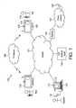
- FIG. 1shows a communication system 100 comprising a packet-based network 101 such as the Internet; and further comprising a separate television broadcasting network 108 such as a terrestrial, satellite or cable television network.
- a plurality of computer terminals 102are shown coupled to the Internet 101 , each comprising a network interface for communicating over the Internet.
- a plurality of television sets 103are also shown coupled to the Internet 101 , each of which also comprises a network interface for communicating over the Internet.
- each television set 103further comprises a television receiver for receiving analogue and/or digital television signals which are broadcast over the television network 108 .
- a television set 103could be arranged to receive packet-based television signals over the Internet 101 or other such packet-based network.
- broadcast televisionis still popular at the time of writing and so in preferred embodiments the television set 103 will comprise a television receiver for receiving broadcasts at least.
- broadcast signalsare transmitted indiscriminately, without transmitting to selected destination devices and regardless of whether the end-user has selected to receive the signal (although a decryption key or such like may still be required so that only authorised users can derive meaningful information from the television signal for viewing).
- Packet-based communicationson the other hand are point-to-point, with an address of the intended destination device being included in the packets. In the case of packet-based television signals transmitted over the Internet, these are still point-to-multipoint communications rather than a broadcast.
- Each computer terminal 102is installed with a communication client application 110 .
- Each computer terminal 102also comprises an audio transceiver 111 comprising a speaker and microphone, e.g. in the form of a headset or handset, or a built-in speaker and microphone.
- Most computer terminals 102preferably also comprise a webcam 112 .
- each television set 103comprises an embedded processor and memory installed with a version of the communication client application 113 specially adapted for running on a television set.
- Each television set 103also comprises a webcam 115 and an audio transceiver with speaker and microphone, or is connected or communicable with such components.
- an audio transceiveris provided in a remote control unit 114 of the television 103 , discussed shortly.
- the communication client applications 110 and 113are preferably peer-to-peer clients for setting-up and conducting VoIP calls according to peer-to-peer principles as discussed above.
- a peer-to-peer backend server 104is coupled to the Internet 101 for receiving registration requests from the client applications 111 and 113 .
- the back-end server 104is arranged to distribute UIC certificates to the respective client applications 111 and 113 running on the computer terminals 102 and television sets 103 in response to the registration requests. Once registered and thus in possession of a UIC certificate, the client applications 111 and/or 113 can look-up one another's addresses, exchange and authenticate one another's certificates, and thus establish a voice or video call over the Internet 101 .
- other kinds of communication clientcould alternatively be used, e.g. based on centralized server-based call set-up.
- the communication system 100may comprise a telephone network 107 such as a circuit-switched network, and a gateway 106 connecting between the Internet 101 and the telephone network 107 .
- a gateway version of the client applicationis arranged to run on the gateway 106 , and a communication client application 110 or 113 running on a computer terminal 102 or television set 103 is thus able to establish a call with a dedicated phone unit 109 of the telephone network 107 .
- Thisis achieved by establishing a connection with the client on the gateway 106 using peer-to-peer call set-up and then supplying the relevant telephone number to the gateway 107 (effectively the user's client 110 or 113 sees the gateway 106 as a peer).
- the phone network 107may for example comprise a fixed-line network (“landline”) and/or a mobile cellular network.
- Each television set 103has an associated remote control unit 114 , an example of which is illustrated in FIG. 2 .
- the remote control unit(or just “remote control”) comprises a microphone 201 , speaker 202 , a first remote interface in the form of an infrared (IR) transmitter 203 , and a second remote interface in the form of a short-range RF interface 204 such as a Bluetooth interface.
- the microphone 201 and speaker 202are operatively coupled to the Bluetooth interface 204 .
- the remote control 114is thus arranged to communicate voice signals from the microphone 201 to the television 103 via the Bluetooth interface 204 , and to receive voice signals from the television 103 via the Bluetooth interface 204 for playing out of the speaker 202 .
- the remote control 114further comprises a plurality of buttons operatively coupled to the infrared transmitter 203 , arranged so as to allow the user to control the television 103 via the infrared transmitter 203 .
- the buttonscomprise a “standby” button 205 for setting the television into a low-power mode.
- the buttonsfurther comprise numerical or alphanumeric buttons 206 for changing channel or supplying other numerical or alphanumerical data to the television 103 ; function buttons 208 for controlling various functions of the television 103 , e.g. for controlling a cursor and/or menu system; and optionally dedicated calling buttons 207 for performing specific dedicated operations relating to the calling functionality of the client application 113 , e.g. “call”, “hang up”, or buttons for zooming in and out during a video call.
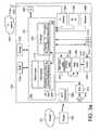
- FIG. 3 ais a schematic block diagram of a television set 103 according to an exemplary embodiment of the present invention.
- the television set 103is a dedicated television unit in the sense that its primary purpose is as a television, and is designed to fulfil the role of a family or household television. However, at the same time it is additionally provided with secondary embedded functionality such as VoIP calling.
- the televisions set 103comprises, within a single casing: an embedded processing apparatus 301 ; a random access memory (RAM) 319 ; and an embedded non-volatile storage device 318 which may comprise an electronically erasable and reprogrammable memory (EEPROM or “flash” memory), a magnetic storage medium, and/or a one-time writable ROM.
- the non-volatile storage device 318is coupled to the processing apparatus 301 and stores a basic operating system (OS) 326 , a television application 330 , and a communication client application 113 such as a VoIP client.
- the processing apparatus 301is arranged to execute the operating system 326 , e.g.
- the operating system 326is configured to load the television application 330 and client application 113 into RAM 319 and schedule them for execution on the processing apparatus 301 .
- the processing apparatus 301is thus arranged to run the television application 330 and client application 113 under control of the operating system 326 .
- only a minimal operating system 326may be required, in the form of a basic scheduler.
- the television set 103further comprises, within the same casing: a video frame buffer 320 and user interface (UI) frame buffer 322 , video hardware 324 , a screen 309 , an amplifier 314 and speaker 316 or output to an external speaker or headphones, a television receiver 304 , an external audio-video (AV) input 306 such as a SCART or HDMI input from an external source, a webcam or webcam input 308 for connecting to an external webcam, a network interface 302 in the form of a first short-range RF transceiver such as a wi-fi transceiver, a first remote interface 310 in the form of an infrared (IR) receiver, and a second remote interface in the form of a second short-range RF transceiver 312 such as a Bluetooth transceiver.
- a first short-range RF transceiversuch as a wi-fi transceiver
- a first remote interface 310in the form of an infrared (IR) receiver
- the video frame buffer 320 and user interface (UI) frame buffer 322each have an input coupled to the processing apparatus 301 .
- the video hardware 324has an input coupled to the outputs of the video frame buffer 320 and UI frame buffer 322 .
- the screen 309has an input to the output of the video hardware 324 .
- the frame buffers 320 and 322could be dedicated hardware buffers or alternatively could be implemented in a general purpose memory.
- the amplifier 314has an input coupled to the processing apparatus 301 and an output coupled to the speaker 316 .
- the processing apparatus 301is further coupled to the network interface 302 , television receiver 304 , auxiliary input 306 , webcam input 308 , infrared interface 310 , and Bluetooth interface 312 .
- any or all of the above componentsmay be coupled to the processing apparatus 301 via intermediate components such as a bus and/or cache (not shown), as will be understood by a person skilled in the art.
- the television receiver 304comprises an input for connecting to at least one reception means such as an antenna, satellite dish or cable line, and is thus arranged to receive television broadcast signals from the television network 108 via the reception means.
- the television receiver 304is a hardware front-end which may comprise for example: sampling circuitry, a low noise amplifier, a filter, a mixer, and/or an analogue-to-digital converter (ADC).
- ADCan analogue-to-digital converter
- the signal processing enginemay comprise for example: a digital filter, demodulator, demultiplexer, decoder, decryption block, and/or error checking block.
- a digital filterdemodulator
- demultiplexerdecoder
- decryption blockdecryption block
- error checking blockerror checking block
- the signals of a plurality of different concurrent programsare frequency-division multiplexed over the airwaves by being transmitted on different frequencies.
- the television receiver 304will then comprise a tuning circuit to demultiplex the broadcasts and thereby separate out the signal of the required programme.
- the signals of different concurrent programsare each divided into packets and interleaved so as to time-division multiplex the different programs' signals into a transport stream for broadcast.
- the signal processing engine of the television application 330will then comprise a packet filter to demultiplex the packets of different transport streams and so separate out the signal of the required programme.
- Multiple transport streamsmay also be broadcast on different frequencies, requiring a tuner as well.
- one or more of the transport streamsmay comprise additional programme information such as an electronic programme guide (EPG).
- EPGelectronic programme guide
- Video signals for output to the television screen 309may also be received via the AV input 306 from an external source such as a DVD player or games console.
- the television application 330further comprises a UI graphics engine, a remote protocol engine, an application programming interface (API), and a television UI layer.
- the overall operation of the signal processing engine, UI graphics engine, remote protocol engine and APIis controlled by the television UI layer.
- the usercan select which broadcast to view by pressing buttons 205 , 206 , 208 on the remote control 114 , causing the remote control 114 to communicate control signals to the processing apparatus 301 via the infrared transmitter 203 and receiver 310 .
- the usermay also use the buttons in a similar manner to view additional information such as the EPG or control menus, and to navigate the EPG or menus.
- the relevant control signalsare interpreted by the remote protocol engine of the television application 113 , which in turn communicates with the television UI layer.
- the television UI layercontrols the signal processing engine to output the relevant television programme to the video frame buffer 320 , and/or controls the UI graphics engine to output graphics to the UI frame buffer 322 (e.g. to display the graphics of the menu or EPG).
- the frame buffers 320 and/or 322supply their contents to the video hardware 324 for display on the screen 309 .
- the UI frame buffer 322 and video hardware 324may be arranged to overlay UI graphics over the current television programme in a partially transparent manner, and/or to leave at least part of the television programme visible.
- the television set 103comprises a network interface 302 .
- thistakes the form of a wireless transceiver such as a wi-fi transceiver, for communicating wirelessly with a household or office-based wireless router 303 as found in most modern homes or offices.
- the router 303in turn connects to the Internet 101 .
- the network interface 302may comprise other options such as a wired modern or a port to an external wired modem.
- the communication client application 330comprises a protocol stack having an I/O layer which, when executed on the processing apparatus 301 , is operable to transmit and receive signals over the Internet 101 via the network interface 302 .
- the I/O layercomprises a network signalling protocol for transmitting and receiving control signals over the Internet 101 via the network interface 302 .
- the I/O layermay also comprise an API for communicating with the API of the television application 301 .
- the I/O layerfurther comprises a voice engine comprising a voice codec.
- the voice engineis arranged to accept speech signals from the microphone 201 , and to encode those speech signals for transmission over the internet 101 via the network interface 302 .
- the voice engineis also arranged to decode speech signals received over the Internet 101 via the network interface 302 , for output to the television's amplifier 314 and speaker 316 , or to the speaker 202 in the remote control 114 via the Bluetooth interfaces 312 and 204 .
- the I/O layerfurther comprises a video engine comprising a video codec.
- the video engineis arranged to accept video signals from the webcam input 308 , and to encode those video signals for transmission over the Internet 101 via the network interface 302 .
- the video engineis also arranged to decode video signals received over the Internet 101 via the network interface 302 , for output to the UI frame buffer 322 , video hardware 326 and screen 309 .
- the video codeccould output video via the video frame buffer 320 .
- the client application 113comprises a client engine which is responsible for call-set up.
- the client enginecontrols the network signalling protocol engine of the client 113 in order to establish a live voice or video call with another user terminal 102 or 103 over the Internet 101 , preferably using P2P call set-up as discussed above, or potentially using a centralized call set-up via a server.
- the client enginemay also handle other functions such as connection management, authentication, encryption, and/or exchanging presence information with the client applications 111 or 113 of other user terminals (presence information indicates the availability of a user for communication, and is preferably at least partially defined by the respective user themselves).
- the client application 113comprises a client UI layer which is responsible for the client's user interface.
- the client UI layeris operable to generate a client user interface for output to the UI frame buffer 322 , video hardware 324 and screen 309 .
- Thismay be output via the APIs and the UI graphics engine of the TV application 330 under control of the TV UI layer (or alternatively the client application 113 could be provided with its own UI graphics protocol to output graphics to the UI frame buffer 322 directly).
- the client user interfacethus presents the user with on-screen controls which they can activate using buttons 206 , 207 , 208 on the remote control 114 .
- the remote control 114communicates control signals to the processing apparatus 301 via the infrared transmitter 203 and receiver 310 .
- These control signalsmay be interpreted by the UI protocol engine in the television application 330 and then signalled via the APIs to the I/O layer of the client application 113 (or alternatively the I/O layer of the client application 113 could be provided with its own remote control protocol to interpret these control signals directly).
- the protocol of the I/O layer of the client 113communicates with the client UI layer.
- the client UI layeris thus configured to respond to user inputs in order to control the overall operation of the client application 113 , e.g. allowing a user to select contacts to call, hang up, etc.
- FIG. 4illustrates an example user interface which could be displayed on the screen 309 by the client application 113 , when summoned by the user using the relevant buttons of the remote 114 .
- the user interfacemay be displayed only on part of the screen 309 , allowing at least a portion of a currently viewed programme to remain visible; or may alternatively take up the whole screen 309 .
- the displayed user interfacecomprises a number of panels.
- the user interfacemay comprise a first panel 402 showing profile information of the user of the television 103 on which the client 113 is running. E.g.
- the profile informationmay comprise the user's name, an “avatar image” (a picture which the user has chosen to represent themselves), and/or a “mood message” (a short user-defined statement for inclusion in their profile).
- the user interfacemay comprise a second panel 404 showing a list of the user's contacts (preferably the client 113 is configured to only allow calls between users who have agreed to be contacts).
- the user interfacemay comprise a third panel 406 showing a profile of a selected one of the contacts, and/or a fourth panel 408 providing a menu or other controls for selecting to call the selected contact.
- the UI layer of the client 113may be configured to communicate with the UI layer of the television application 330 , via the APIs and the operating system 326 . This allows the client application 113 and television application 330 to negotiate control of the screen 309 and/or speaker 316 or 202 .
- the client application 113 or television application 330takes precedence may depend on the implementation and/or situation. Since the television set 103 is primarily a television, then preferably the client application 113 should require permission from the television application 330 before controlling the screen 309 or speaker 316 or 202 . However, in embodiments a user-defined setting may be provided allowing the user to control whether or not the client application 113 can autonomously take control of the screen 309 and/or speaker 316 or 202 , e.g. to notify the user in event of an incoming call. This setting would preferably be stored in a non-volatile memory 318 and be readable by the client application 113 and/or television application 330 . E.g.
- the television application 330may be configured to read a setting from memory and, if set, to unequivocally allow the client application 113 to control the screen and/or speaker.
- the client application 113may be configured to read a setting from memory and, if set, to control the screen and/or speaker without seeking permission from the television application 330 .
- At least one such user settingis read by the client application 113 , and when set the client application 113 is configured to defer any notifications of incoming VoIP calls or other incoming communication events received over the Internet 101 until a suitable juncture in the user's television viewing. This could mean deferring a notification until after a television programme is finished, or until some other suitable juncture in the programme such as a commercial break. Another possibility would be to defer a notification until after video signals cease to be received via the AV input 306 from an external source such as DVD player or games console.
- incoming communication events signalled asynchronously to the television set 103 over the Internet 101 via the network interface 302are postponed in deference to a higher-priority source such as the television receiver 308 and television network 108 , or AV input 306 and external source.
- deferring a notificationis distinct and advantageous over the mere outright suppression of a notification. Suppressing the notification would mean barring it altogether so as never to be output to the user; whereas deferral requires that the notification will still output to the user, but postponed until some later point in time.
- the client application 113is configured with a mechanism for delineating the viewing activity in question.
- the client application 113will not understand the actual user content of the television programme or such like, so cannot directly tell when one programme ends and another begins, or cannot directly tell the difference between the main programme and the commercial breaks. Therefore a delineation mechanism is required, for which there are a number of options as discussed below.
- a first, preferred mechanisminvolves receiving additional programme information broadcast over the television network 108 .
- the additional programme informationis received by the client application 113 via the television receiver 308 , and comprises timing information which can be used by the client application 113 to delineate the television programme for the purpose of deferring notifications.
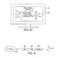
- a digital television broadcastmay comprise audio data 601 and video data 602 of one or more programme streams all interleaved together (i.e. time-division multiplexed) into a combined transport stream for transmission on a particular frequency.
- additional program information 603providing timing information for the one or more programmes (potentially amongst other information such as subtitles and textual programme summaries or précis).
- the additional programme information 603may take the form of a general data stream multiplexed into the transport stream in conjunction with a plurality of programme streams, providing programme information for a plurality of programmes. An example of this would be an electronic program guide (EPG).
- EPGelectronic program guide
- individual respective programme informationmay be provided in the stream of each programme.
- the audio data, video data and additional programme informationare decoded by the signal processing engine of the television application 331 , and the required programme timing information can be accessed by the client application 113 via the APIs under control of the TV UI layer.
- the programme timing information 603comprises programme schedule information such as the EPG. That is, nominal information about when the programme or programmes are scheduled to start and end.
- the API of the client application 113may enable it to access the EPG decoded by the signal processing engine of the television application 331 . The client 113 can thereby determine that the television programme currently being viewed on the screen 309 is scheduled to end at a particular time, and defer the notification until that time.
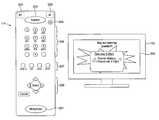
- the client 113determines via the API to the EPG that the television programme currently being viewed is scheduled to run from 8:00 pm to 9:00 pm. If an incoming call is signalled over the Internet 101 and received at the network interface 302 during the program, e.g. say at 8:13 pm, then the client application 113 will temporarily block the notification of the incoming call until the scheduled finishing time at 9:00 pm. A similar process would occur if an incoming IM chat message is received during the programme. Following the scheduled end time of the programme (either at that time or just after), the client application 113 will then take control of the screen 309 in order to display a list 503 of any one or more communication events missed during the programme.
- the list 503preferably comprises a control such as a cursor 505 which can be controlled by the user, e.g. via function buttons 208 on the remote control, to thereby operate the client 113 initiate a return VoIP call or other corresponding packet-based communication with the respective other user.
- a controlsuch as a cursor 505 which can be controlled by the user, e.g. via function buttons 208 on the remote control, to thereby operate the client 113 initiate a return VoIP call or other corresponding packet-based communication with the respective other user.
- the programme timing information 603may comprise a real-time indication of the programme's actual end time (which can be accessed by the client via the API to the television application in a similar manner as discussed above).
- the client 113will not display the list 503 of missed events until the actual end time of 9:02 pm. This advantageously avoids the deferred notifications interfering with the last few minutes of a programme (which could even be the most critical part of the programme in the case of a suspense drama for instance).
- the client 113will also defer any incoming communications received during the overrunning period (e.g. at 9:01 pm).
- the real-time programme timing informationmay also indicate the time of breaks in the programme (typically used as commercial breaks to show advertisements, but potentially also used for other purposes such as news bulletins).
- the client application 113will be enabled to display the list of missed events 503 during the break.
- a second mechanism for delineating the programmeis for the client application 113 to download programme timing information via the Internet 101 and network interface 302 , e.g. from a server of a broadcaster, programme production company or third-party service.
- This downloaded informationcould comprise either schedule information and/or real-time updates to the scheduled times.
- This second mechanismhas the advantages of the first mechanism, with the added advantage of being compatible with legacy technologies in which certain timing information 603 may not be available via the broadcast (most digital television broadcasts nowadays do at least include schedule information such as the EPG, but do not all necessarily provide real-time indications of programme timing, and furthermore analogue broadcasts do not include any programme timing information). This could even be used in conjunction with the former variant of the first mechanism in order to provide updates to the schedule information received in the broadcast 603 .
- a third, less preferred mechanism for delineating the programmeis to provide a timer that can be set by the user.
- the timermay be a feature of the client application 113 , or be a feature of the television application 330 which may be accessed via the APIs.
- the usersets the timer for a predetermined time, and the client application 113 waits until that time before displaying the list of missed events 503 .
- the third mechanismhas the downside of possible interference with the end of an overrunning program, and also has the added downside of requiring an inconvenient user input process.
- this third mechanismhas the advantage of being compatible with legacy technologies such as analogue broadcasts which do not include programme timing information, and without requiring additional server infrastructure to provide such information via the internet 101 .
- a fourth mechanismwould be to provide a user-defined “do not disturb” (DND) setting which the client could assert at the beginning of the programme.
- DNDdo not disturb
- the client application 113is configured to detect when the user de-asserts the DND status, and upon detecting this to automatically display the list of missed events 503 .
- the client application 113may be necessary for the client application 113 to monitor the current time. This could be done based on a local clock 340 , or by receiving updates of the current time from the Internet 101 or television network 108 . However, using the latter variant of the first mechanism, there may be no need to monitor the current time if the programme timing information 603 provides a real-time trigger (as opposed to a real-time update of the end time in hours and minutes of the day). There will also be no need to monitor the current time in the fourth, DND-based mechanism.
- the client application 113may be further configured to return automated messages to the callers of the missed calls (or more generally to the other users who are the originators of the missed communication events).
- the automated messageis returned by the client application 113 when an incoming communication event is received during an ongoing programme, without requiring an input from the local user viewing the programme (the callee). It is transmitted to the other, remote user (the caller) via the network interface 302 and Internet 101 , and informs the caller that the callee is unavailable.
- the automated messageindicates to the caller the reason why the callee is unavailable (watching TV).
- the client application 113may be configured to use the programme schedule or other timing information to predict when the callee is likely to become available again (i.e. when the current programme is due to finish), and may include this predicted information in the automated message for the benefit of the caller. This could even be incorporated as a new kind of presence status.
- the inventionis not limited to on-screen notifications.
- the notificationsmay comprise audible notifications output via a speaker 316 or 202 , and it may desirable to defer the audible notifications so that they do not disrupt the user's experience of a current television programme.
- the inventionis not limited to any particular mechanism for delineating a television program or other viewing activity.
- notificationscould be deferred until the user changes channel, changes to a different source such as from television programmes to AV input 308 , or accesses the EPG.
- the clientcould access the decoded audio via an API to the television application 330 and attempt to determine when a commercial break occurs based on a change in peak or average volume levels (broadcasters tend to increase the volume during commercial breaks to get the user's attention, though this method would be vulnerable to false alarms e.g. during action sequences of a programme).
- programmedoes not limit to any particular kind of programme content, and could refer for example to a film, soap opera, documentary, sporting event, news program, etc.
- DSPsdedicated signal processors
- the client application and television applicationcould each be run on a different respective CPU embedded in the television set 103 .
- Some or all of the functionality of the television application 330could alternatively be implemented in dedicated hardware, including the possibility of hardwired signal processing apparatus in the television receiver front-end 304 .
- the inventionis not limited to use in a television set having the above components including television screen all within one single self-contained casing.
- the inventioncould be implemented in a set-top box for plugging into such a television set. In that case the diagram would be similar to that of FIG. 3 a but with the television hardware 320 , 322 , 324 and screen 309 replaced by an audio-video (AV) output.
- AVaudio-video
- the client application 113may be installed on a games console 105 .
- the console 105comprises a processing apparatus 301 in the form of one or more CPUs, coupled to: a non-volatile storage means 318 such as hard drive, flash memory and/or optical disc drive; a RAM 319 ; a webcam or input 308 from a webcam; and a network interface 302 such as a wi-fi transceiver for accessing a packet-based network such as the Internet 101 (e.g. via wireless router 303 ).
- the processing apparatus 301is further coupled to dedicated gaming graphics hardware 325 and dedicated audio hardware 327 , which in turn connect to an audio-video (AV) output 307 for connecting the console 105 to a television set 103 .
- the processing apparatus 301is further coupled to an additional wireless interface 315 operating on a band suitable for communicating to and from a wireless gamepad 317 or other such game controller (or alternatively a wired interface could be provided).
- the non-volatile storage 318supplies the client application 113 and a video game 331 (not necessarily from the same storage unit or medium), both arranged for execution on the processing apparatus 301 (preferably under control of an operating system 326 ).
- the video gamecomprises a console library arranged to handle the I/O with the various devices 315 , 325 , 327 and 308 ; a game engine arranged to perform the underlying game logic, and a game UI layer arranged to generate game graphics and sound for output via the console library and graphics and sound hardware 325 , 327 .
- the video game 331also comprises an API for communicating with the API of the client application 113 via the OS 326 .
- the APIsmay be used to signal occurrences within the video game 331 to the client 113 , and these signalled occurrences may be used by the client 113 to delineate the video game for the purpose of deferring notifications. For example, notifications of an incoming call could be deferred until a player dies or loses within the video game. This may be a more suitable juncture to notify the user than mid-game when he or she may not wish to be distracted.
- the present inventioncan be applied to any media appliance having video apparatus for outputting signals to a television screen.
- the video apparatusmay comprise any combination of dedicated hardware and/or regions of memory storing software modules, with any software modules being executed on either the same or a different processor unit as the client application 103 .
- the video apparatusmay take different forms.
- the video apparatusmay be said to comprise a combination of the frame buffers 320 and 322 , video hardware 324 , and/or a region of the non-volatile memory 318 storing signal processing code of the television application.
- the video apparatusmay be said to comprise the video hardware 325 , external AV output 307 , and/or a region of the non-volatile storage 318 storing graphics processing code of the video game 331 .
- the present inventionneed not be limited by television broadcasts.
- packet-based television servicesthere may be interest in the idea of a dedicated television set or set-top box with the capability of receiving packet-based television signals, either over the Internet or a dedicated packet-based service.
- the present inventionis not limited particularly to VoIP or to a peer-to-peer topology.
- Other packet-based networks, protocols and methods of call set-upmay also be used.
Landscapes
- Engineering & Computer Science (AREA)
- Signal Processing (AREA)
- Multimedia (AREA)
- Human Computer Interaction (AREA)
- Computer Networks & Wireless Communication (AREA)
- Business, Economics & Management (AREA)
- General Engineering & Computer Science (AREA)
- Databases & Information Systems (AREA)
- Library & Information Science (AREA)
- Software Systems (AREA)
- General Business, Economics & Management (AREA)
- Marketing (AREA)
- Telephonic Communication Services (AREA)
- Information Transfer Between Computers (AREA)
- Two-Way Televisions, Distribution Of Moving Picture Or The Like (AREA)
Abstract
Description
Claims (23)
Priority Applications (3)
| Application Number | Priority Date | Filing Date | Title |
|---|---|---|---|
| US14/677,569US10454862B2 (en) | 2010-03-31 | 2015-04-02 | Media appliance |
| US16/570,188US11496427B2 (en) | 2010-03-31 | 2019-09-13 | Media appliance |
| US17/959,959US20230022815A1 (en) | 2010-03-31 | 2022-10-04 | Media appliance |
Applications Claiming Priority (2)
| Application Number | Priority Date | Filing Date | Title |
|---|---|---|---|
| GB1005458.3 | 2010-03-31 | ||
| GBGB1005458.3AGB201005458D0 (en) | 2010-03-31 | 2010-03-31 | Media appliance |
Related Child Applications (1)
| Application Number | Title | Priority Date | Filing Date |
|---|---|---|---|
| US14/677,569ContinuationUS10454862B2 (en) | 2010-03-31 | 2015-04-02 | Media appliance |
Publications (2)
| Publication Number | Publication Date |
|---|---|
| US20110244955A1 US20110244955A1 (en) | 2011-10-06 |
| US8998720B2true US8998720B2 (en) | 2015-04-07 |
Family
ID=42228710
Family Applications (4)
| Application Number | Title | Priority Date | Filing Date |
|---|---|---|---|
| US12/843,293Active2032-08-02US8998720B2 (en) | 2010-03-31 | 2010-07-26 | Media appliance |
| US14/677,569Active2031-07-31US10454862B2 (en) | 2010-03-31 | 2015-04-02 | Media appliance |
| US16/570,188ActiveUS11496427B2 (en) | 2010-03-31 | 2019-09-13 | Media appliance |
| US17/959,959PendingUS20230022815A1 (en) | 2010-03-31 | 2022-10-04 | Media appliance |
Family Applications After (3)
| Application Number | Title | Priority Date | Filing Date |
|---|---|---|---|
| US14/677,569Active2031-07-31US10454862B2 (en) | 2010-03-31 | 2015-04-02 | Media appliance |
| US16/570,188ActiveUS11496427B2 (en) | 2010-03-31 | 2019-09-13 | Media appliance |
| US17/959,959PendingUS20230022815A1 (en) | 2010-03-31 | 2022-10-04 | Media appliance |
Country Status (9)
| Country | Link |
|---|---|
| US (4) | US8998720B2 (en) |
| EP (4) | EP2543179B1 (en) |
| CN (2) | CN102823238B (en) |
| DK (2) | DK3576395T3 (en) |
| ES (2) | ES2744567T3 (en) |
| FI (1) | FI3576395T3 (en) |
| GB (1) | GB201005458D0 (en) |
| PT (2) | PT3229452T (en) |
| WO (1) | WO2011121006A1 (en) |
Cited By (5)
| Publication number | Priority date | Publication date | Assignee | Title |
|---|---|---|---|---|
| US20130273978A1 (en)* | 2010-12-08 | 2013-10-17 | Microsoft Corporation | Controlling Audio Signals |
| US20170109327A1 (en)* | 2015-05-20 | 2017-04-20 | Shenzhen Skyworth-Rgb Electronic Co., Ltd | Method and system for webpage processing |
| US10350496B2 (en) | 2013-01-31 | 2019-07-16 | Sony Interactive Entertainment Inc. | Game device, game control method, game control program, matching server, matching control method, and matching control program |
| US10491962B2 (en) | 2018-03-14 | 2019-11-26 | Rovi Guides, Inc. | Systems and methods for presenting event notifications, based on active applications in a social group, on devices notwithstanding a user instruction to disable event notifications |
| US10749828B2 (en) | 2018-03-14 | 2020-08-18 | Rovi Guides, Inc. | Systems and methods for presenting event notifications, based on trending communications, on devices notwithstanding a user instruction to disable event notifications |
Families Citing this family (22)
| Publication number | Priority date | Publication date | Assignee | Title |
|---|---|---|---|---|
| GB2475237B (en)* | 2009-11-09 | 2016-01-06 | Skype | Apparatus and method for controlling communication signalling and media |
| GB201005454D0 (en) | 2010-03-31 | 2010-05-19 | Skype Ltd | Television apparatus |
| GB2479180B (en) | 2010-03-31 | 2016-06-01 | Skype | System of user devices |
| GB201005458D0 (en) | 2010-03-31 | 2010-05-19 | Skype Ltd | Media appliance |
| GB201005465D0 (en) | 2010-03-31 | 2010-05-19 | Skype Ltd | Television set |
| US10291660B2 (en) | 2010-12-31 | 2019-05-14 | Skype | Communication system and method |
| US10404762B2 (en)* | 2010-12-31 | 2019-09-03 | Skype | Communication system and method |
| US8963982B2 (en) | 2010-12-31 | 2015-02-24 | Skype | Communication system and method |
| US9717090B2 (en) | 2010-12-31 | 2017-07-25 | Microsoft Technology Licensing, Llc | Providing notifications of call-related services |
| EP2608610A1 (en)* | 2011-12-22 | 2013-06-26 | France Telecom | Method for notifying a user of a device of the occurrence of an event |
| US9019336B2 (en) | 2011-12-30 | 2015-04-28 | Skype | Making calls using an additional terminal |
| US9448685B1 (en)* | 2012-11-20 | 2016-09-20 | Amazon Technologies, Inc. | Preemptive event notification for media experience |
| GB201301452D0 (en) | 2013-01-28 | 2013-03-13 | Microsoft Corp | Providing notifications of call-related services |
| US8612534B1 (en) | 2013-01-31 | 2013-12-17 | Electronic Arts Inc. | Pausing of content delivery in push notifications |
| US9989667B2 (en)* | 2013-12-19 | 2018-06-05 | Halliburton Energy Services, Inc. | Pore size classification in subterranean formations based on nuclear magnetic resonance (NMR) relaxation distributions |
| US9794783B2 (en)* | 2015-01-16 | 2017-10-17 | Jeffrey Huang | Machine-to-machine visual code generation and recognition method and system for device communications |
| US10135941B2 (en)* | 2016-02-18 | 2018-11-20 | International Business Machines Corporation | Managing push notifications on portable devices |
| US20180048921A1 (en)* | 2016-08-12 | 2018-02-15 | Microsoft Technology Licensing, Llc | Real-time playback diagnostics |
| US11241623B2 (en)* | 2017-05-05 | 2022-02-08 | Sony Interactive Entertainment LLC | Instant streaming of a mobile user interface without application install |
| JP6767319B2 (en)* | 2017-07-31 | 2020-10-14 | 株式会社ソニー・インタラクティブエンタテインメント | Information processing device and file copy method |
| US10848815B2 (en)* | 2018-08-23 | 2020-11-24 | Dish Network L.L.C. | Outputting a message during downloading or buffering |
| US11325044B2 (en)* | 2019-03-07 | 2022-05-10 | Sony Interactive Entertainment LLC | Video game guidance system |
Citations (112)
| Publication number | Priority date | Publication date | Assignee | Title |
|---|---|---|---|---|
| US5014125A (en) | 1989-05-05 | 1991-05-07 | Cableshare, Inc. | Television system for the interactive distribution of selectable video presentations |
| WO1994001428A1 (en) | 1992-07-06 | 1994-01-20 | Rhone-Poulenc Rorer International (Holdings) Inc. | Asymmetric synthesis of hexahydrodibenzofurans by stereospecific inversion of ortho substituted 2-phenylcyclohexanols |
| WO1994006230A2 (en) | 1992-09-02 | 1994-03-17 | Octus, Inc. | Multimedia message transmitter |
| US5519433A (en) | 1991-11-20 | 1996-05-21 | Zing Systems, L.P. | Interactive television security through transaction time stamping |
| WO1996025006A1 (en) | 1995-02-10 | 1996-08-15 | Flexydial Pty. Ltd. | Interactive broadcasting system |
| US5559549A (en) | 1992-12-09 | 1996-09-24 | Discovery Communications, Inc. | Television program delivery system |
| US5561709A (en) | 1991-10-03 | 1996-10-01 | Viscorp | Apparatus and method for electronic device for information services |
| US5583927A (en) | 1995-05-01 | 1996-12-10 | Bell Communications Research, Inc. | Method and apparatus for integrating telephone and broadband networks |
| WO1996041478A1 (en) | 1995-06-07 | 1996-12-19 | Tv Guide On Screen | Electronic television program guide schedule system and method with data feed access |
| US5600364A (en) | 1992-12-09 | 1997-02-04 | Discovery Communications, Inc. | Network controller for cable television delivery systems |
| US5657072A (en) | 1996-04-10 | 1997-08-12 | Microsoft Corporation | Interactive entertainment network system and method for providing program listings during non-peak times |
| WO1997035258A1 (en) | 1996-03-21 | 1997-09-25 | Mpath Interactive, Inc. | Network match maker for selecting clients based on attributes of servers and communication links |
| US5694163A (en) | 1995-09-28 | 1997-12-02 | Intel Corporation | Method and apparatus for viewing of on-line information service chat data incorporated in a broadcast television program |
| WO1998001589A1 (en) | 1996-07-08 | 1998-01-15 | Mannesmann Ag | Process for producing weldless steel pipes |
| EP0834798A2 (en) | 1996-10-07 | 1998-04-08 | Compaq Computer Corporation | Integrated content guide for interactive selection of content and services on personal computer systems |
| WO1998017064A1 (en) | 1996-10-16 | 1998-04-23 | Gemstar Development Corporation | Access to internet data through a television system |
| WO1998021664A1 (en) | 1996-11-14 | 1998-05-22 | Interactive Broadcaster Services Corporation | Computer network chat room based on channel broadcast in real time |
| US5764916A (en) | 1996-09-27 | 1998-06-09 | Ichat, Inc. | Method and apparatus for real time communication over a computer network |
| WO1998028698A1 (en) | 1996-12-20 | 1998-07-02 | Network Computer, Inc. | Internet multiplexer for broadcast and other information |
| WO1998029818A1 (en) | 1996-12-31 | 1998-07-09 | Intel Corporation | Method and apparatus for analyzing online user typing to determine or verify facts |
| US5781226A (en) | 1995-11-13 | 1998-07-14 | General Instrument Corporation Of Delaware | Network virtual memory for a cable television settop terminal |
| US5793365A (en) | 1996-01-02 | 1998-08-11 | Sun Microsystems, Inc. | System and method providing a computer user interface enabling access to distributed workgroup members |
| US5796393A (en) | 1996-11-08 | 1998-08-18 | Compuserve Incorporated | System for intergrating an on-line service community with a foreign service |
| US5805763A (en) | 1995-05-05 | 1998-09-08 | Microsoft Corporation | System and method for automatically recording programs in an interactive viewing system |
| US5812123A (en) | 1994-11-29 | 1998-09-22 | Microsoft Corporation | System for displaying programming information |
| US5818441A (en) | 1995-06-15 | 1998-10-06 | Intel Corporation | System and method for simulating two-way connectivity for one way data streams |
| US5833468A (en) | 1996-01-24 | 1998-11-10 | Frederick R. Guy | Remote learning system using a television signal and a network connection |
| US5841468A (en) | 1996-04-26 | 1998-11-24 | Convergence. Com | System and method for routing data messages through a cable transmission system |
| US5844615A (en) | 1997-01-16 | 1998-12-01 | General Instrument Corporation | Communication of VBI data in digital television data streams |
| US5905493A (en) | 1996-11-13 | 1999-05-18 | Unalink Communications, Inc. | Color coded instructional scheme for computers and the like system, method and article of manufacture |
| US5937404A (en) | 1997-04-23 | 1999-08-10 | Appaloosa Interactive Corporation | Apparatus for bleaching a de-activated link in a web page of any distinguishing color or feature representing an active link |
| US5956693A (en) | 1996-07-19 | 1999-09-21 | Geerlings; Huib | Computer system for merchant communication to customers |
| US5974446A (en) | 1996-10-24 | 1999-10-26 | Academy Of Applied Science | Internet based distance learning system for communicating between server and clients wherein clients communicate with each other or with teacher using different communication techniques via common user interface |
| US5988078A (en) | 1991-12-04 | 1999-11-23 | Gemstar Development Corp. | Method and apparatus for receiving customized television programming information by transmitting geographic location to a service provider through a wide-area network |
| US6002394A (en) | 1995-10-02 | 1999-12-14 | Starsight Telecast, Inc. | Systems and methods for linking television viewers with advertisers and broadcasters |
| US6014136A (en) | 1996-03-05 | 2000-01-11 | Casio Computer Co., Ltd. | Data processing apparatus with communication function |
| US6018768A (en) | 1996-03-08 | 2000-01-25 | Actv, Inc. | Enhanced video programming system and method for incorporating and displaying retrieved integrated internet information segments |
| US6021433A (en) | 1996-01-26 | 2000-02-01 | Wireless Internet, Inc. | System and method for transmission of data |
| US6081830A (en) | 1997-10-09 | 2000-06-27 | Gateway 2000, Inc. | Automatic linking to program-specific computer chat rooms |
| US6175619B1 (en) | 1998-07-08 | 2001-01-16 | At&T Corp. | Anonymous voice communication using on-line controls |
| US6177931B1 (en) | 1996-12-19 | 2001-01-23 | Index Systems, Inc. | Systems and methods for displaying and recording control interface with television programs, video, advertising information and program scheduling information |
| US6184878B1 (en) | 1997-12-23 | 2001-02-06 | Sarnoff Corporation | Interactive world wide web access using a set top terminal in a video on demand system |
| US6339784B1 (en) | 1997-05-20 | 2002-01-15 | America Online, Inc. | Self-policing, rate limiting online forums |
| US6388714B1 (en) | 1995-10-02 | 2002-05-14 | Starsight Telecast Inc | Interactive computer system for providing television schedule information |
| US20020128033A1 (en) | 1998-11-30 | 2002-09-12 | Burgess Shelia Jean | Communications control method and apparatus |
| US6499053B1 (en) | 1999-06-30 | 2002-12-24 | International Business Machines Corporation | Master/slave architecture for a distributed chat application in a bandwidth constrained network |
| US6510557B1 (en) | 1997-01-03 | 2003-01-21 | Texas Instruments Incorporated | Apparatus for the integration of television signals and information from an information service provider |
| US6545722B1 (en) | 1998-01-09 | 2003-04-08 | Douglas G. Brown | Methods and systems for providing television related services via a networked personal computer |
| US6677968B1 (en) | 1997-02-24 | 2004-01-13 | America Online, Inc. | User definable on-line co-user lists |
| US20040052341A1 (en) | 2002-09-18 | 2004-03-18 | I-Hau Yeh | System for automatic notification of caller ID, e-mail identification and short message |
| WO2004066604A1 (en) | 2003-01-22 | 2004-08-05 | Nimcat Networks Inc. | Call transfer system, method and network devices |
| US20040194146A1 (en) | 2000-02-15 | 2004-09-30 | Bates Cary Lee | Set top box and methods for using the same |
| EP1475939A1 (en) | 2003-05-09 | 2004-11-10 | Microsoft Corporation | Instant messaging embedded games |
| WO2005009019A2 (en) | 2003-07-16 | 2005-01-27 | Skype Limited | Peer-to-peer telephone system and method |
| WO2005008524A1 (en) | 2003-07-16 | 2005-01-27 | Joltid Ltd. | Distributed database system |
| US20050034079A1 (en) | 2003-08-05 | 2005-02-10 | Duraisamy Gunasekar | Method and system for providing conferencing services |
| US20050041793A1 (en)* | 2003-07-14 | 2005-02-24 | Fulton Paul R. | System and method for active mobile collaboration |
| JP2005086765A (en) | 2003-09-11 | 2005-03-31 | Sharp Corp | Tv receiver, cellular phone, and tv receiver built-in cellular phone device |
| US20050090234A1 (en) | 2003-10-07 | 2005-04-28 | Hitachi, Ltd. | Incoming call notification system and method |
| US20050122963A1 (en) | 2003-12-05 | 2005-06-09 | Seong-Joon Jeon | IP-based voice/video communication system and call pickup/forwarding method |
| US20060093998A1 (en)* | 2003-03-21 | 2006-05-04 | Roel Vertegaal | Method and apparatus for communication between humans and devices |
| WO2006051492A2 (en) | 2004-11-15 | 2006-05-18 | Koninklijke Philips Electronics N.V. | Method and network device for assisting a user in selecting content |
| WO2006058036A3 (en) | 2004-11-22 | 2006-07-06 | Searete Llc | Call transfer to proximate devices |
| US20070115348A1 (en) | 2005-10-27 | 2007-05-24 | Cisco Technology, Inc. | Method and system for automatic scheduling of a conference |
| US20070116210A1 (en) | 2005-08-05 | 2007-05-24 | Xiao-Guang Li | Tv set with a telephone calls-rejecting function |
| US20070121599A1 (en) | 2005-11-21 | 2007-05-31 | Bce Inc. | Method, system and apparatus for announcing caller information over a television link |
| EP1816843A1 (en) | 2006-02-07 | 2007-08-08 | Broadcom Corporation | Set top box supporting bridging between a packet switched network and the public switched telephone network |
| WO2007118250A2 (en) | 2006-04-12 | 2007-10-18 | Cisco Technology, Inc. | Transferring a communications exchange |
| US20070265091A1 (en)* | 2006-04-25 | 2007-11-15 | Aguilar Jr Maximino | Method to generate virtual world event notifications from within a persistent world game |
| WO2007137485A1 (en) | 2006-05-26 | 2007-12-06 | Huawei Technologies Co., Ltd. | Methods and systems for implementing call transfer and home network of user terminal |
| WO2008015369A1 (en) | 2006-08-01 | 2008-02-07 | Nds Limited | Call management |
| US20080081698A1 (en) | 2006-09-29 | 2008-04-03 | Wormald Christopher R | Im contact list entry as a game in progress designate |
| EP1909467A1 (en) | 2006-10-05 | 2008-04-09 | Avaya Technology Llc | Centralized controller for distributed handling of telecommunications features |
| US20080134278A1 (en) | 2006-12-05 | 2008-06-05 | General Instrument Corporation | Set-Top Box and Method for Operating the Set-Top Box Using a Mobile Telephone |
| US20080157998A1 (en) | 2006-12-27 | 2008-07-03 | Funai Electric Co., Ltd. | Television system with installed telephone function, and remote controller device directed thereto |
| US20080235587A1 (en) | 2007-03-23 | 2008-09-25 | Nextwave Broadband Inc. | System and method for content distribution |
| US20080239995A1 (en) | 2007-03-30 | 2008-10-02 | David Cheng-Wei Lee | Method and system for the automatic configuration of conference resources |
| US20080271100A1 (en) | 2002-10-11 | 2008-10-30 | Hill George E | Method Using A Set-Top Box And Communicating Between A Remote Data Network And A Wireless Communication Network |
| US20090017792A1 (en) | 2004-05-12 | 2009-01-15 | Fumiaki Matsumoto | Mobile telephone having broadcast reception function |
| US20090069002A1 (en) | 2007-09-07 | 2009-03-12 | Samsung Electronics Co., Ltd. | System to provide entertainment in association with telecommunication service |
| EP2056601A1 (en) | 2007-11-05 | 2009-05-06 | Samsung Electronics Co., Ltd. | Method for providing viewing information for displaying a list of channels viewed by call recipients |
| EP2063612A1 (en) | 2006-04-10 | 2009-05-27 | Skype Limited | User interface for a communication device |
| US20090136016A1 (en) | 2007-11-08 | 2009-05-28 | Meelik Gornoi | Transferring a communication event |
| US20090214007A1 (en) | 2006-04-17 | 2009-08-27 | Ryan Van Wyk | System and method for providing telephone call notification and management in a network environment |
| WO2009115048A1 (en) | 2008-03-20 | 2009-09-24 | 华为技术有限公司 | Method, system and equipment for shifting call based on a mobile terminal with the same number and a soft terminal |
| US20090271820A1 (en) | 2008-04-24 | 2009-10-29 | Samsung Electronics Co . , Ltd. | Method of recommending broadcasting contents and recommending apparatus therefor in multimedia contents reproducing device |
| US20090271834A1 (en) | 2000-06-30 | 2009-10-29 | Comcast Ip Holdings I, Llc | Advanced Set Top Terminal Having a Video Call Feature |
| US20090288132A1 (en) | 2008-05-14 | 2009-11-19 | Samsung Electronics Co. Ltd. | Method and communication system for controlling appliance device using a mobile device |
| US7627341B2 (en) | 2005-01-31 | 2009-12-01 | Microsoft Corporation | User authentication via a mobile telephone |
| US20100037300A1 (en) | 2008-08-05 | 2010-02-11 | Samsung Electronics Co., Ltd. | Method and apparatus for notifying remote user interface client about event of remote user interface server in home network |
| WO2010026190A1 (en) | 2008-09-05 | 2010-03-11 | Skype Limited | Communication system and method |
| WO2010026189A1 (en) | 2008-09-05 | 2010-03-11 | Skype Limited | Communication system and method |
| WO2010026194A1 (en) | 2008-09-05 | 2010-03-11 | Skype Limited | Communication system and method |
| WO2010026187A1 (en) | 2008-09-05 | 2010-03-11 | Skype Limited | Communications system |
| WO2010026188A1 (en) | 2008-09-05 | 2010-03-11 | Skype Limited | Communication system and method |
| WO2010026191A1 (en) | 2008-09-05 | 2010-03-11 | Skype Limited | Communication system and method |
| WO2010026196A1 (en) | 2008-09-05 | 2010-03-11 | Skype Limited | Communication system and method |
| US20100106769A1 (en) | 2008-10-28 | 2010-04-29 | At&T Intellectual Property I, L.P. | Apparatus and method for managing media content delivery for multiple communication devices |
| US7716283B2 (en) | 2005-02-16 | 2010-05-11 | Microsoft Corporation | Television system video conferencing |
| US20100254670A1 (en) | 2009-04-06 | 2010-10-07 | International Buisness Machines Corporation | Content Recorder Multi-Angle Viewing and Playback |
| US7908630B2 (en) | 1998-12-30 | 2011-03-15 | At&T Intellectual Property Ii, L.P. | Method and apparatus for internet co-browsing over cable television and controlled through computer telephony |
| US20110109715A1 (en) | 2009-11-06 | 2011-05-12 | Xiangpeng Jing | Automated wireless three-dimensional (3D) video conferencing via a tunerless television device |
| US20110222466A1 (en) | 2010-03-10 | 2011-09-15 | Aleksandar Pance | Dynamically adjustable communications services and communications links |
| GB2479180A (en) | 2010-03-31 | 2011-10-05 | Skype Ltd | Switching between user devices during a VoIP call |
| US20110243140A1 (en) | 2010-03-30 | 2011-10-06 | Telefonaktiebolaget L M Ericsson | RSTP Tracking |
| WO2011120948A1 (en) | 2010-03-31 | 2011-10-06 | Skype Limited | Television apparatus |
| US20110244955A1 (en) | 2010-03-31 | 2011-10-06 | Skype Limited | Media Appliance |
| US20110242270A1 (en) | 2010-03-31 | 2011-10-06 | David Dinka | Television set |
| US20110281568A1 (en) | 2010-05-13 | 2011-11-17 | Rovi Technologies Corporation | Management of incoming telephony communications in a local media network |
| US20120076285A1 (en) | 2005-07-21 | 2012-03-29 | At&T Intellectual Property I, L.P. | Enhanced caller id with recipient-selected caller information display |
| US8175588B2 (en) | 2004-11-22 | 2012-05-08 | The Invention Science Fund I, Llc | Bring call here selectively |
| US20140208367A1 (en) | 1998-08-26 | 2014-07-24 | United Video Properties, Inc. | Television chat system |
Family Cites Families (11)
| Publication number | Priority date | Publication date | Assignee | Title |
|---|---|---|---|---|
| US20040073953A1 (en)* | 1990-09-28 | 2004-04-15 | Qi Xu | Audio/video apparatus for use with a cable television network |
| GB9222767D0 (en)* | 1992-10-30 | 1992-12-09 | Canon Res Ct Europe Ltd | Processing image data |
| US6993245B1 (en)* | 1999-11-18 | 2006-01-31 | Vulcan Patents Llc | Iterative, maximally probable, batch-mode commercial detection for audiovisual content |
| US6674458B1 (en)* | 2000-07-21 | 2004-01-06 | Koninklijke Philips Electronics N.V. | Methods and apparatus for switching between a representative presence mode and one or more other modes in a camera-based system |
| WO2004034235A2 (en)* | 2002-10-11 | 2004-04-22 | Walker Digital, Llc | Method and apparatus for outputting a message at a game machine |
| US7503006B2 (en)* | 2003-09-25 | 2009-03-10 | Microsoft Corporation | Visual indication of current voice speaker |
| US8045802B2 (en)* | 2006-12-01 | 2011-10-25 | Yahoo! Inc. | End of program pattern detector |
| US9367521B2 (en)* | 2008-01-30 | 2016-06-14 | International Business Machines Corporation | Content and context based handling of instant messages |
| US9266017B1 (en)* | 2008-12-03 | 2016-02-23 | Electronic Arts Inc. | Virtual playbook with user controls |
| US20110111735A1 (en)* | 2009-11-06 | 2011-05-12 | Apple Inc. | Phone hold mechanism |
| US20110183754A1 (en)* | 2010-01-25 | 2011-07-28 | Mansour Ali Saleh Alghamdi | Game system based on real time and location of user |
- 2010
- 2010-03-31GBGBGB1005458.3Apatent/GB201005458D0/ennot_activeCeased
- 2010-07-26USUS12/843,293patent/US8998720B2/enactiveActive
- 2011
- 2011-03-30FIFIEP19186594.8Tpatent/FI3576395T3/enactive
- 2011-03-30CNCN201180018068.7Apatent/CN102823238B/enactiveActive
- 2011-03-30EPEP11712236.6Apatent/EP2543179B1/enactiveActive
- 2011-03-30DKDK19186594.8Tpatent/DK3576395T3/enactive
- 2011-03-30WOPCT/EP2011/054881patent/WO2011121006A1/enactiveApplication Filing
- 2011-03-30EPEP19186594.8Apatent/EP3576395B1/enactiveActive
- 2011-03-30EPEP16207628.5Apatent/EP3229452B1/enactiveActive
- 2011-03-30ESES16207628Tpatent/ES2744567T3/enactiveActive
- 2011-03-30CNCN201610418505.9Apatent/CN105915976A/enactivePending
- 2011-03-30PTPT16207628Tpatent/PT3229452T/enunknown
- 2011-03-30PTPT191865948Tpatent/PT3576395T/enunknown
- 2011-03-30DKDK16207628.5Tpatent/DK3229452T3/enactive
- 2011-03-30ESES11712236.6Tpatent/ES2634035T3/enactiveActive
- 2011-03-30EPEP24223677.6Apatent/EP4557751A3/enactivePending
- 2015
- 2015-04-02USUS14/677,569patent/US10454862B2/enactiveActive
- 2019
- 2019-09-13USUS16/570,188patent/US11496427B2/enactiveActive
- 2022
- 2022-10-04USUS17/959,959patent/US20230022815A1/enactivePending
Patent Citations (126)
| Publication number | Priority date | Publication date | Assignee | Title |
|---|---|---|---|---|
| US5014125A (en) | 1989-05-05 | 1991-05-07 | Cableshare, Inc. | Television system for the interactive distribution of selectable video presentations |
| US5561709A (en) | 1991-10-03 | 1996-10-01 | Viscorp | Apparatus and method for electronic device for information services |
| US5519433A (en) | 1991-11-20 | 1996-05-21 | Zing Systems, L.P. | Interactive television security through transaction time stamping |
| US5988078A (en) | 1991-12-04 | 1999-11-23 | Gemstar Development Corp. | Method and apparatus for receiving customized television programming information by transmitting geographic location to a service provider through a wide-area network |
| WO1994001428A1 (en) | 1992-07-06 | 1994-01-20 | Rhone-Poulenc Rorer International (Holdings) Inc. | Asymmetric synthesis of hexahydrodibenzofurans by stereospecific inversion of ortho substituted 2-phenylcyclohexanols |
| WO1994006230A2 (en) | 1992-09-02 | 1994-03-17 | Octus, Inc. | Multimedia message transmitter |
| US5559549A (en) | 1992-12-09 | 1996-09-24 | Discovery Communications, Inc. | Television program delivery system |
| US5600364A (en) | 1992-12-09 | 1997-02-04 | Discovery Communications, Inc. | Network controller for cable television delivery systems |
| US5589892A (en) | 1993-09-09 | 1996-12-31 | Knee; Robert A. | Electronic television program guide schedule system and method with data feed access |
| US5812123A (en) | 1994-11-29 | 1998-09-22 | Microsoft Corporation | System for displaying programming information |
| WO1996025006A1 (en) | 1995-02-10 | 1996-08-15 | Flexydial Pty. Ltd. | Interactive broadcasting system |
| US5583927A (en) | 1995-05-01 | 1996-12-10 | Bell Communications Research, Inc. | Method and apparatus for integrating telephone and broadband networks |
| US5805763A (en) | 1995-05-05 | 1998-09-08 | Microsoft Corporation | System and method for automatically recording programs in an interactive viewing system |
| WO1996041478A1 (en) | 1995-06-07 | 1996-12-19 | Tv Guide On Screen | Electronic television program guide schedule system and method with data feed access |
| US5818441A (en) | 1995-06-15 | 1998-10-06 | Intel Corporation | System and method for simulating two-way connectivity for one way data streams |
| US5694163A (en) | 1995-09-28 | 1997-12-02 | Intel Corporation | Method and apparatus for viewing of on-line information service chat data incorporated in a broadcast television program |
| US6002394A (en) | 1995-10-02 | 1999-12-14 | Starsight Telecast, Inc. | Systems and methods for linking television viewers with advertisers and broadcasters |
| US6388714B1 (en) | 1995-10-02 | 2002-05-14 | Starsight Telecast Inc | Interactive computer system for providing television schedule information |
| US5781226A (en) | 1995-11-13 | 1998-07-14 | General Instrument Corporation Of Delaware | Network virtual memory for a cable television settop terminal |
| US5793365A (en) | 1996-01-02 | 1998-08-11 | Sun Microsystems, Inc. | System and method providing a computer user interface enabling access to distributed workgroup members |
| US5833468A (en) | 1996-01-24 | 1998-11-10 | Frederick R. Guy | Remote learning system using a television signal and a network connection |
| US6021433A (en) | 1996-01-26 | 2000-02-01 | Wireless Internet, Inc. | System and method for transmission of data |
| US6014136A (en) | 1996-03-05 | 2000-01-11 | Casio Computer Co., Ltd. | Data processing apparatus with communication function |
| US6018768A (en) | 1996-03-08 | 2000-01-25 | Actv, Inc. | Enhanced video programming system and method for incorporating and displaying retrieved integrated internet information segments |
| WO1997035258A1 (en) | 1996-03-21 | 1997-09-25 | Mpath Interactive, Inc. | Network match maker for selecting clients based on attributes of servers and communication links |
| US5657072A (en) | 1996-04-10 | 1997-08-12 | Microsoft Corporation | Interactive entertainment network system and method for providing program listings during non-peak times |
| US5841468A (en) | 1996-04-26 | 1998-11-24 | Convergence. Com | System and method for routing data messages through a cable transmission system |
| WO1998001589A1 (en) | 1996-07-08 | 1998-01-15 | Mannesmann Ag | Process for producing weldless steel pipes |
| US5956693A (en) | 1996-07-19 | 1999-09-21 | Geerlings; Huib | Computer system for merchant communication to customers |
| US5764916A (en) | 1996-09-27 | 1998-06-09 | Ichat, Inc. | Method and apparatus for real time communication over a computer network |
| US6172677B1 (en) | 1996-10-07 | 2001-01-09 | Compaq Computer Corporation | Integrated content guide for interactive selection of content and services on personal computer systems with multiple sources and multiple media presentation |
| EP0834798A2 (en) | 1996-10-07 | 1998-04-08 | Compaq Computer Corporation | Integrated content guide for interactive selection of content and services on personal computer systems |
| WO1998017064A1 (en) | 1996-10-16 | 1998-04-23 | Gemstar Development Corporation | Access to internet data through a television system |
| US5974446A (en) | 1996-10-24 | 1999-10-26 | Academy Of Applied Science | Internet based distance learning system for communicating between server and clients wherein clients communicate with each other or with teacher using different communication techniques via common user interface |
| US5796393A (en) | 1996-11-08 | 1998-08-18 | Compuserve Incorporated | System for intergrating an on-line service community with a foreign service |
| US5905493A (en) | 1996-11-13 | 1999-05-18 | Unalink Communications, Inc. | Color coded instructional scheme for computers and the like system, method and article of manufacture |
| WO1998021664A1 (en) | 1996-11-14 | 1998-05-22 | Interactive Broadcaster Services Corporation | Computer network chat room based on channel broadcast in real time |
| US5828839A (en) | 1996-11-14 | 1998-10-27 | Interactive Broadcaster Services Corp. | Computer network chat room based on channel broadcast in real time |
| US6177931B1 (en) | 1996-12-19 | 2001-01-23 | Index Systems, Inc. | Systems and methods for displaying and recording control interface with television programs, video, advertising information and program scheduling information |
| WO1998028698A1 (en) | 1996-12-20 | 1998-07-02 | Network Computer, Inc. | Internet multiplexer for broadcast and other information |
| WO1998029818A1 (en) | 1996-12-31 | 1998-07-09 | Intel Corporation | Method and apparatus for analyzing online user typing to determine or verify facts |
| US6510557B1 (en) | 1997-01-03 | 2003-01-21 | Texas Instruments Incorporated | Apparatus for the integration of television signals and information from an information service provider |
| US5844615A (en) | 1997-01-16 | 1998-12-01 | General Instrument Corporation | Communication of VBI data in digital television data streams |
| US6677968B1 (en) | 1997-02-24 | 2004-01-13 | America Online, Inc. | User definable on-line co-user lists |
| US5937404A (en) | 1997-04-23 | 1999-08-10 | Appaloosa Interactive Corporation | Apparatus for bleaching a de-activated link in a web page of any distinguishing color or feature representing an active link |
| US6339784B1 (en) | 1997-05-20 | 2002-01-15 | America Online, Inc. | Self-policing, rate limiting online forums |
| US6081830A (en) | 1997-10-09 | 2000-06-27 | Gateway 2000, Inc. | Automatic linking to program-specific computer chat rooms |
| US6184878B1 (en) | 1997-12-23 | 2001-02-06 | Sarnoff Corporation | Interactive world wide web access using a set top terminal in a video on demand system |
| US6545722B1 (en) | 1998-01-09 | 2003-04-08 | Douglas G. Brown | Methods and systems for providing television related services via a networked personal computer |
| US6175619B1 (en) | 1998-07-08 | 2001-01-16 | At&T Corp. | Anonymous voice communication using on-line controls |
| US20140208367A1 (en) | 1998-08-26 | 2014-07-24 | United Video Properties, Inc. | Television chat system |
| US20020128033A1 (en) | 1998-11-30 | 2002-09-12 | Burgess Shelia Jean | Communications control method and apparatus |
| US7908630B2 (en) | 1998-12-30 | 2011-03-15 | At&T Intellectual Property Ii, L.P. | Method and apparatus for internet co-browsing over cable television and controlled through computer telephony |
| US6499053B1 (en) | 1999-06-30 | 2002-12-24 | International Business Machines Corporation | Master/slave architecture for a distributed chat application in a bandwidth constrained network |
| US20040194146A1 (en) | 2000-02-15 | 2004-09-30 | Bates Cary Lee | Set top box and methods for using the same |
| US20090271834A1 (en) | 2000-06-30 | 2009-10-29 | Comcast Ip Holdings I, Llc | Advanced Set Top Terminal Having a Video Call Feature |
| US20040052341A1 (en) | 2002-09-18 | 2004-03-18 | I-Hau Yeh | System for automatic notification of caller ID, e-mail identification and short message |
| US20080271100A1 (en) | 2002-10-11 | 2008-10-30 | Hill George E | Method Using A Set-Top Box And Communicating Between A Remote Data Network And A Wireless Communication Network |
| WO2004066604A1 (en) | 2003-01-22 | 2004-08-05 | Nimcat Networks Inc. | Call transfer system, method and network devices |
| US20060093998A1 (en)* | 2003-03-21 | 2006-05-04 | Roel Vertegaal | Method and apparatus for communication between humans and devices |
| EP1475939A1 (en) | 2003-05-09 | 2004-11-10 | Microsoft Corporation | Instant messaging embedded games |
| US20050041793A1 (en)* | 2003-07-14 | 2005-02-24 | Fulton Paul R. | System and method for active mobile collaboration |
| WO2005008524A1 (en) | 2003-07-16 | 2005-01-27 | Joltid Ltd. | Distributed database system |
| WO2005009019A2 (en) | 2003-07-16 | 2005-01-27 | Skype Limited | Peer-to-peer telephone system and method |
| US20050034079A1 (en) | 2003-08-05 | 2005-02-10 | Duraisamy Gunasekar | Method and system for providing conferencing services |
| JP2005086765A (en) | 2003-09-11 | 2005-03-31 | Sharp Corp | Tv receiver, cellular phone, and tv receiver built-in cellular phone device |
| US20050090234A1 (en) | 2003-10-07 | 2005-04-28 | Hitachi, Ltd. | Incoming call notification system and method |
| US20050122963A1 (en) | 2003-12-05 | 2005-06-09 | Seong-Joon Jeon | IP-based voice/video communication system and call pickup/forwarding method |
| US20090017792A1 (en) | 2004-05-12 | 2009-01-15 | Fumiaki Matsumoto | Mobile telephone having broadcast reception function |
| WO2006051492A2 (en) | 2004-11-15 | 2006-05-18 | Koninklijke Philips Electronics N.V. | Method and network device for assisting a user in selecting content |
| US8175588B2 (en) | 2004-11-22 | 2012-05-08 | The Invention Science Fund I, Llc | Bring call here selectively |
| WO2006058036A3 (en) | 2004-11-22 | 2006-07-06 | Searete Llc | Call transfer to proximate devices |
| US7627341B2 (en) | 2005-01-31 | 2009-12-01 | Microsoft Corporation | User authentication via a mobile telephone |
| US7716283B2 (en) | 2005-02-16 | 2010-05-11 | Microsoft Corporation | Television system video conferencing |
| US20120076285A1 (en) | 2005-07-21 | 2012-03-29 | At&T Intellectual Property I, L.P. | Enhanced caller id with recipient-selected caller information display |
| US20070116210A1 (en) | 2005-08-05 | 2007-05-24 | Xiao-Guang Li | Tv set with a telephone calls-rejecting function |
| US20070115348A1 (en) | 2005-10-27 | 2007-05-24 | Cisco Technology, Inc. | Method and system for automatic scheduling of a conference |
| US20070121599A1 (en) | 2005-11-21 | 2007-05-31 | Bce Inc. | Method, system and apparatus for announcing caller information over a television link |
| US8068591B2 (en) | 2005-11-21 | 2011-11-29 | Bce Inc. | Method, system and apparatus for announcing caller information over a television link |
| EP1816843A1 (en) | 2006-02-07 | 2007-08-08 | Broadcom Corporation | Set top box supporting bridging between a packet switched network and the public switched telephone network |
| EP2114062A1 (en) | 2006-04-10 | 2009-11-04 | Skype Limited | User interface for a communication device |
| EP2063612A1 (en) | 2006-04-10 | 2009-05-27 | Skype Limited | User interface for a communication device |
| WO2007118250A2 (en) | 2006-04-12 | 2007-10-18 | Cisco Technology, Inc. | Transferring a communications exchange |
| US20090214007A1 (en) | 2006-04-17 | 2009-08-27 | Ryan Van Wyk | System and method for providing telephone call notification and management in a network environment |
| US20120083248A1 (en) | 2006-04-17 | 2012-04-05 | At&T Intellectual Property I, Lp | System and method for providing telephone call notification and management in a network environment |
| US20070265091A1 (en)* | 2006-04-25 | 2007-11-15 | Aguilar Jr Maximino | Method to generate virtual world event notifications from within a persistent world game |
| WO2007137485A1 (en) | 2006-05-26 | 2007-12-06 | Huawei Technologies Co., Ltd. | Methods and systems for implementing call transfer and home network of user terminal |
| WO2008015369A1 (en) | 2006-08-01 | 2008-02-07 | Nds Limited | Call management |
| US20080081698A1 (en) | 2006-09-29 | 2008-04-03 | Wormald Christopher R | Im contact list entry as a game in progress designate |
| EP1909467A1 (en) | 2006-10-05 | 2008-04-09 | Avaya Technology Llc | Centralized controller for distributed handling of telecommunications features |
| US20080134278A1 (en) | 2006-12-05 | 2008-06-05 | General Instrument Corporation | Set-Top Box and Method for Operating the Set-Top Box Using a Mobile Telephone |
| US20080157998A1 (en) | 2006-12-27 | 2008-07-03 | Funai Electric Co., Ltd. | Television system with installed telephone function, and remote controller device directed thereto |
| US20080235587A1 (en) | 2007-03-23 | 2008-09-25 | Nextwave Broadband Inc. | System and method for content distribution |
| US20080239995A1 (en) | 2007-03-30 | 2008-10-02 | David Cheng-Wei Lee | Method and system for the automatic configuration of conference resources |
| US20090069002A1 (en) | 2007-09-07 | 2009-03-12 | Samsung Electronics Co., Ltd. | System to provide entertainment in association with telecommunication service |
| EP2056601A1 (en) | 2007-11-05 | 2009-05-06 | Samsung Electronics Co., Ltd. | Method for providing viewing information for displaying a list of channels viewed by call recipients |
| US20090136016A1 (en) | 2007-11-08 | 2009-05-28 | Meelik Gornoi | Transferring a communication event |
| WO2009115048A1 (en) | 2008-03-20 | 2009-09-24 | 华为技术有限公司 | Method, system and equipment for shifting call based on a mobile terminal with the same number and a soft terminal |
| US20110021200A1 (en) | 2008-03-20 | 2011-01-27 | Huawei Technologies Co., Ltd. | Method, system and equipment for shifting call based on a mobile terminal with the same number and a soft terminal |
| US20090271820A1 (en) | 2008-04-24 | 2009-10-29 | Samsung Electronics Co . , Ltd. | Method of recommending broadcasting contents and recommending apparatus therefor in multimedia contents reproducing device |
| US20090288132A1 (en) | 2008-05-14 | 2009-11-19 | Samsung Electronics Co. Ltd. | Method and communication system for controlling appliance device using a mobile device |
| US20100037300A1 (en) | 2008-08-05 | 2010-02-11 | Samsung Electronics Co., Ltd. | Method and apparatus for notifying remote user interface client about event of remote user interface server in home network |
| WO2010026189A1 (en) | 2008-09-05 | 2010-03-11 | Skype Limited | Communication system and method |
| WO2010026191A1 (en) | 2008-09-05 | 2010-03-11 | Skype Limited | Communication system and method |
| WO2010026196A1 (en) | 2008-09-05 | 2010-03-11 | Skype Limited | Communication system and method |
| WO2010026190A1 (en) | 2008-09-05 | 2010-03-11 | Skype Limited | Communication system and method |
| WO2010026194A1 (en) | 2008-09-05 | 2010-03-11 | Skype Limited | Communication system and method |
| WO2010026187A1 (en) | 2008-09-05 | 2010-03-11 | Skype Limited | Communications system |
| WO2010026188A1 (en) | 2008-09-05 | 2010-03-11 | Skype Limited | Communication system and method |
| US20100106769A1 (en) | 2008-10-28 | 2010-04-29 | At&T Intellectual Property I, L.P. | Apparatus and method for managing media content delivery for multiple communication devices |
| US20100254670A1 (en) | 2009-04-06 | 2010-10-07 | International Buisness Machines Corporation | Content Recorder Multi-Angle Viewing and Playback |
| US20110109715A1 (en) | 2009-11-06 | 2011-05-12 | Xiangpeng Jing | Automated wireless three-dimensional (3D) video conferencing via a tunerless television device |
| US20110222466A1 (en) | 2010-03-10 | 2011-09-15 | Aleksandar Pance | Dynamically adjustable communications services and communications links |
| US20110243140A1 (en) | 2010-03-30 | 2011-10-06 | Telefonaktiebolaget L M Ericsson | RSTP Tracking |
| US20110242270A1 (en) | 2010-03-31 | 2011-10-06 | David Dinka | Television set |
| WO2011120992A1 (en) | 2010-03-31 | 2011-10-06 | Skype Limited | Television set |
| US20110243141A1 (en) | 2010-03-31 | 2011-10-06 | Skype Limited | System of User Devices |
| WO2011120991A1 (en) | 2010-03-31 | 2011-10-06 | Skype Limited | System of user devices |
| WO2011121006A1 (en) | 2010-03-31 | 2011-10-06 | Skype Limited | Media appliance |
| US20110242266A1 (en) | 2010-03-31 | 2011-10-06 | Helen Blackburn | Television apparatus |
| US20110244955A1 (en) | 2010-03-31 | 2011-10-06 | Skype Limited | Media Appliance |
| WO2011120948A1 (en) | 2010-03-31 | 2011-10-06 | Skype Limited | Television apparatus |
| US8369498B2 (en) | 2010-03-31 | 2013-02-05 | Skype | Television set |
| US8711200B2 (en) | 2010-03-31 | 2014-04-29 | Skype | Television apparatus |
| GB2479180A (en) | 2010-03-31 | 2011-10-05 | Skype Ltd | Switching between user devices during a VoIP call |
| US20110281568A1 (en) | 2010-05-13 | 2011-11-17 | Rovi Technologies Corporation | Management of incoming telephony communications in a local media network |
Non-Patent Citations (28)
| Title |
|---|
| "Corrected Notice of Allowance", U.S. Appl. No. 12/843,569, Feb. 21, 2014, 2 pages. |
| "Final Office Action", U.S. Appl. No. 12/843,527, Oct. 24, 2013, 10 pages. |
| "Final Office Action", U.S. Appl. No. 12/843,543, (Aug. 3, 2012), 8 pages. |
| "Final Office Action", U.S. Appl. No. 12/843,569, (Oct. 9, 2012), 20 pages. |
| "International Search Report and Written Opinion", Application No. PCT/EP2011/054781, (May 23, 2011), 13 pages. |
| "International Search Report and Written Opinion", Application No. PCT/EP2011/054862, (Jun. 27, 2011), 17 pages. |
| "International Search Report and Written Opinion", Application No. PCT/EP2011/054864, (May 31, 2011), 13 pages. |
| "Non-Final Office Action", U.S. Appl. No. 12/843,527, (Mar. 29, 2013), 11 pages. |
| "Non-Final Office Action", U.S. Appl. No. 12/843,527, Mar. 14, 2014, 14 pages. |
| "Non-Final Office Action", U.S. Appl. No. 12/843,543, (May 29, 2012), 9 pages. |
| "Non-Final Office Action", U.S. Appl. No. 12/843,569, (Apr. 19, 2013),23 pages. |
| "Non-Final Office Action", U.S. Appl. No. 12/843,569, (Apr. 4, 2012), 13 pages. |
| "Notice of Allowance", U.S. Appl. No. 12/843,543, (Oct. 15, 2012), 6 pages. |
| "Notice of Allowance", U.S. Appl. No. 12/843,569, Dec. 11, 2013, 11 pages. |
| "Search Report", Application No. GB1005462.5, (Jul. 28, 2011), 2 pages. |
| (http://www.multichannel.com/article/439701-Verizon Debuts Caller ID on FIOS TV I nThree markets.php) (Dec. 10, 2009). |
| Comcast's Universal Caller IDS: See who's calling-right from your TV and PC! (https://www.comcast.net/calerid/). |
| Extended European Search Report dated Feb. 28, 2011 in EP06011155.6. |
| Extended European Search Report dated Jan. 21, 2011 in EP07075232.4. |
| Fixmer, Rob, Windows 98 Feature Combines TV, Terminal and the Internet, New York Times, (Aug. 18, 1998). |
| Intel and NBC Work to Speed the Development of Enhanced DTV, printed from the Internet at http://www.intel.com/pressroom/archive/releases/Cn041999.htm on Jul. 15, 1999. |
| Menezes, Excite@Home Sets Voice Offerings, Broadband Week, p. 45 (Jul. 5, 1999. |
| Notification of Transmittal of the International Search Report and the Written Opinion of the International Searching Authority for Int'l Application No. PCT/EP2011/054881; Date Mailed: Jul. 25, 2011, 18 pp. |
| The Advanced TV Enhancement Forum homepage printed from the Internet at http://www.atvef.com on Jul. 15, 1999. |
| The Wink Communications Company homepage, printed from the Internet at http://www.wink.com/company/index.html on Jul. 13, 1999. |
| WebTV Plus Features: E-mail, printed from the Internet at http://www.webtv.net/products/plus/wantmore3.html on Jul. 15, 1999. |
| WebTV Plus Features: TV Features, printed from the Internet at http://www.webtv.net/products/plus/wantmore.html on Jul. 15, 1999. |
| WebTV Plus Service, printed from the Internet at http://www.webtv.net/products/plus on Jul. 15, 1999. |
Cited By (10)
| Publication number | Priority date | Publication date | Assignee | Title |
|---|---|---|---|---|
| US20130273978A1 (en)* | 2010-12-08 | 2013-10-17 | Microsoft Corporation | Controlling Audio Signals |
| US9698916B2 (en)* | 2010-12-08 | 2017-07-04 | Skype | Controlling audio signals |
| US10350496B2 (en) | 2013-01-31 | 2019-07-16 | Sony Interactive Entertainment Inc. | Game device, game control method, game control program, matching server, matching control method, and matching control program |
| US20170109327A1 (en)* | 2015-05-20 | 2017-04-20 | Shenzhen Skyworth-Rgb Electronic Co., Ltd | Method and system for webpage processing |
| US9898443B2 (en)* | 2015-05-20 | 2018-02-20 | Shenzhen Skyworth-Rgb Electronic Co., Ltd | Method and system for webpage processing |
| US10491962B2 (en) | 2018-03-14 | 2019-11-26 | Rovi Guides, Inc. | Systems and methods for presenting event notifications, based on active applications in a social group, on devices notwithstanding a user instruction to disable event notifications |
| US10749828B2 (en) | 2018-03-14 | 2020-08-18 | Rovi Guides, Inc. | Systems and methods for presenting event notifications, based on trending communications, on devices notwithstanding a user instruction to disable event notifications |
| US11362974B2 (en) | 2018-03-14 | 2022-06-14 | ROVl GUIDES, INC. | Systems and methods for presenting event notifications, based on trending communications, on devices notwithstanding a user instruction to disable event notifications |
| US11855943B2 (en) | 2018-03-14 | 2023-12-26 | Rovi Guides, Inc. | Systems and methods for presenting event notifications, based on trending communications, on devices notwithstanding a user instruction to disable event notifications |
| US12273311B2 (en) | 2018-03-14 | 2025-04-08 | Adeia Guides Inc. | Systems and methods for presenting event notifications, based on trending communications, on devices notwithstanding a user instruction to disable event notifications |
Also Published As
| Publication number | Publication date |
|---|---|
| US20110244955A1 (en) | 2011-10-06 |
| US20150215250A1 (en) | 2015-07-30 |
| CN102823238B (en) | 2016-08-03 |
| EP3229452B1 (en) | 2019-07-17 |
| PT3229452T (en) | 2019-09-23 |
| EP4557751A3 (en) | 2025-08-20 |
| CN102823238A (en) | 2012-12-12 |
| EP3229452A1 (en) | 2017-10-11 |
| EP4557751A2 (en) | 2025-05-21 |
| US20230022815A1 (en) | 2023-01-26 |
| PT3576395T (en) | 2025-02-06 |
| EP3576395B1 (en) | 2025-01-08 |
| US20200084167A1 (en) | 2020-03-12 |
| EP2543179A1 (en) | 2013-01-09 |
| DK3229452T3 (en) | 2019-09-16 |
| EP3576395A1 (en) | 2019-12-04 |
| EP2543179B1 (en) | 2017-04-19 |
| GB201005458D0 (en) | 2010-05-19 |
| FI3576395T3 (en) | 2025-02-17 |
| ES2634035T3 (en) | 2017-09-26 |
| US10454862B2 (en) | 2019-10-22 |
| CN105915976A (en) | 2016-08-31 |
| US11496427B2 (en) | 2022-11-08 |
| WO2011121006A1 (en) | 2011-10-06 |
| ES2744567T3 (en) | 2020-02-25 |
| DK3576395T3 (en) | 2025-02-17 |
Similar Documents
| Publication | Publication Date | Title |
|---|---|---|
| US20230022815A1 (en) | Media appliance | |
| US9258511B2 (en) | Indicia of contact viewing activity | |
| US8369498B2 (en) | Television set | |
| US8885601B2 (en) | Switching user devices in a packet-based network | |
| US8407749B2 (en) | Communication system and method | |
| US20110242268A1 (en) | Television Appliance | |
| US8520050B2 (en) | Communication system and method |
Legal Events
| Date | Code | Title | Description |
|---|---|---|---|
| AS | Assignment | Owner name:SKYPE LIMITED, IRELAND Free format text:ASSIGNMENT OF ASSIGNORS INTEREST;ASSIGNORS:DINKA, DAVID;GIER, GISELA;SIGNING DATES FROM 20100605 TO 20100712;REEL/FRAME:024742/0546 | |
| AS | Assignment | Owner name:JPMORGAN CHASE BANK, N.A., AS ADMINISTRATIVE AGENT Free format text:SECURITY AGREEMENT;ASSIGNORS:SKYPE LIMITED;SKYPE IRELAND TECHNOLOGIES HOLDINGS LIMITED;REEL/FRAME:025970/0786 Effective date:20110301 | |
| AS | Assignment | Owner name:SKYPE LIMITED, CALIFORNIA Free format text:RELEASE OF SECURITY INTEREST;ASSIGNOR:JPMORGAN CHASE BANK, N.A.;REEL/FRAME:027289/0923 Effective date:20111013 | |
| AS | Assignment | Owner name:SKYPE, IRELAND Free format text:CHANGE OF NAME;ASSIGNOR:SKYPE LIMITED;REEL/FRAME:028691/0596 Effective date:20111115 | |
| AS | Assignment | Owner name:ROVI TECHNOLOGIES CORPORATION, CALIFORNIA Free format text:ASSIGNMENT OF ASSIGNORS INTEREST;ASSIGNOR:SKYPE;REEL/FRAME:034092/0814 Effective date:20141014 | |
| STCF | Information on status: patent grant | Free format text:PATENTED CASE | |
| MAFP | Maintenance fee payment | Free format text:PAYMENT OF MAINTENANCE FEE, 4TH YEAR, LARGE ENTITY (ORIGINAL EVENT CODE: M1551); ENTITY STATUS OF PATENT OWNER: LARGE ENTITY Year of fee payment:4 | |
| AS | Assignment | Owner name:HPS INVESTMENT PARTNERS, LLC, AS COLLATERAL AGENT, Free format text:SECURITY INTEREST;ASSIGNORS:ROVI SOLUTIONS CORPORATION;ROVI TECHNOLOGIES CORPORATION;ROVI GUIDES, INC.;AND OTHERS;REEL/FRAME:051143/0468 Effective date:20191122 Owner name:HPS INVESTMENT PARTNERS, LLC, AS COLLATERAL AGENT, NEW YORK Free format text:SECURITY INTEREST;ASSIGNORS:ROVI SOLUTIONS CORPORATION;ROVI TECHNOLOGIES CORPORATION;ROVI GUIDES, INC.;AND OTHERS;REEL/FRAME:051143/0468 Effective date:20191122 | |
| AS | Assignment | Owner name:MORGAN STANLEY SENIOR FUNDING, INC., AS COLLATERAL Free format text:PATENT SECURITY AGREEMENT;ASSIGNORS:ROVI SOLUTIONS CORPORATION;ROVI TECHNOLOGIES CORPORATION;ROVI GUIDES, INC.;AND OTHERS;REEL/FRAME:051110/0006 Effective date:20191122 Owner name:MORGAN STANLEY SENIOR FUNDING, INC., AS COLLATERAL AGENT, MARYLAND Free format text:PATENT SECURITY AGREEMENT;ASSIGNORS:ROVI SOLUTIONS CORPORATION;ROVI TECHNOLOGIES CORPORATION;ROVI GUIDES, INC.;AND OTHERS;REEL/FRAME:051110/0006 Effective date:20191122 | |
| AS | Assignment | Owner name:BANK OF AMERICA, N.A., NORTH CAROLINA Free format text:SECURITY INTEREST;ASSIGNORS:ROVI SOLUTIONS CORPORATION;ROVI TECHNOLOGIES CORPORATION;ROVI GUIDES, INC.;AND OTHERS;REEL/FRAME:053468/0001 Effective date:20200601 | |
| AS | Assignment | Owner name:ROVI GUIDES, INC., CALIFORNIA Free format text:RELEASE BY SECURED PARTY;ASSIGNOR:HPS INVESTMENT PARTNERS, LLC;REEL/FRAME:053458/0749 Effective date:20200601 Owner name:ROVI SOLUTIONS CORPORATION, CALIFORNIA Free format text:RELEASE BY SECURED PARTY;ASSIGNOR:HPS INVESTMENT PARTNERS, LLC;REEL/FRAME:053458/0749 Effective date:20200601 Owner name:TIVO SOLUTIONS, INC., CALIFORNIA Free format text:RELEASE BY SECURED PARTY;ASSIGNOR:HPS INVESTMENT PARTNERS, LLC;REEL/FRAME:053458/0749 Effective date:20200601 Owner name:VEVEO, INC., CALIFORNIA Free format text:RELEASE BY SECURED PARTY;ASSIGNOR:HPS INVESTMENT PARTNERS, LLC;REEL/FRAME:053458/0749 Effective date:20200601 Owner name:ROVI TECHNOLOGIES CORPORATION, CALIFORNIA Free format text:RELEASE BY SECURED PARTY;ASSIGNOR:HPS INVESTMENT PARTNERS, LLC;REEL/FRAME:053458/0749 Effective date:20200601 Owner name:TIVO SOLUTIONS, INC., CALIFORNIA Free format text:RELEASE BY SECURED PARTY;ASSIGNOR:MORGAN STANLEY SENIOR FUNDING, INC.;REEL/FRAME:053481/0790 Effective date:20200601 Owner name:ROVI SOLUTIONS CORPORATION, CALIFORNIA Free format text:RELEASE BY SECURED PARTY;ASSIGNOR:MORGAN STANLEY SENIOR FUNDING, INC.;REEL/FRAME:053481/0790 Effective date:20200601 Owner name:ROVI TECHNOLOGIES CORPORATION, CALIFORNIA Free format text:RELEASE BY SECURED PARTY;ASSIGNOR:MORGAN STANLEY SENIOR FUNDING, INC.;REEL/FRAME:053481/0790 Effective date:20200601 Owner name:VEVEO, INC., CALIFORNIA Free format text:RELEASE BY SECURED PARTY;ASSIGNOR:MORGAN STANLEY SENIOR FUNDING, INC.;REEL/FRAME:053481/0790 Effective date:20200601 Owner name:ROVI GUIDES, INC., CALIFORNIA Free format text:RELEASE BY SECURED PARTY;ASSIGNOR:MORGAN STANLEY SENIOR FUNDING, INC.;REEL/FRAME:053481/0790 Effective date:20200601 | |
| MAFP | Maintenance fee payment | Free format text:PAYMENT OF MAINTENANCE FEE, 8TH YEAR, LARGE ENTITY (ORIGINAL EVENT CODE: M1552); ENTITY STATUS OF PATENT OWNER: LARGE ENTITY Year of fee payment:8 | |
| AS | Assignment | Owner name:ADEIA TECHNOLOGIES INC., CALIFORNIA Free format text:CHANGE OF NAME;ASSIGNOR:ROVI TECHNOLOGIES CORPORATION;REEL/FRAME:069047/0828 Effective date:20220815 |