US8998448B2 - LED tube lamp - Google Patents
LED tube lampDownload PDFInfo
- Publication number
- US8998448B2 US8998448B2US13/091,135US201113091135AUS8998448B2US 8998448 B2US8998448 B2US 8998448B2US 201113091135 AUS201113091135 AUS 201113091135AUS 8998448 B2US8998448 B2US 8998448B2
- Authority
- US
- United States
- Prior art keywords
- cover
- tube lamp
- led tube
- lamp according
- leds
- Prior art date
- Legal status (The legal status is an assumption and is not a legal conclusion. Google has not performed a legal analysis and makes no representation as to the accuracy of the status listed.)
- Expired - Fee Related, expires
Links
Images


Classifications
- F—MECHANICAL ENGINEERING; LIGHTING; HEATING; WEAPONS; BLASTING
- F21—LIGHTING
- F21K—NON-ELECTRIC LIGHT SOURCES USING LUMINESCENCE; LIGHT SOURCES USING ELECTROCHEMILUMINESCENCE; LIGHT SOURCES USING CHARGES OF COMBUSTIBLE MATERIAL; LIGHT SOURCES USING SEMICONDUCTOR DEVICES AS LIGHT-GENERATING ELEMENTS; LIGHT SOURCES NOT OTHERWISE PROVIDED FOR
- F21K9/00—Light sources using semiconductor devices as light-generating elements, e.g. using light-emitting diodes [LED] or lasers
- F21K9/60—Optical arrangements integrated in the light source, e.g. for improving the colour rendering index or the light extraction
- F21K9/69—Details of refractors forming part of the light source
- F21K9/17—
- F—MECHANICAL ENGINEERING; LIGHTING; HEATING; WEAPONS; BLASTING
- F21—LIGHTING
- F21K—NON-ELECTRIC LIGHT SOURCES USING LUMINESCENCE; LIGHT SOURCES USING ELECTROCHEMILUMINESCENCE; LIGHT SOURCES USING CHARGES OF COMBUSTIBLE MATERIAL; LIGHT SOURCES USING SEMICONDUCTOR DEVICES AS LIGHT-GENERATING ELEMENTS; LIGHT SOURCES NOT OTHERWISE PROVIDED FOR
- F21K9/00—Light sources using semiconductor devices as light-generating elements, e.g. using light-emitting diodes [LED] or lasers
- F21K9/20—Light sources comprising attachment means
- F21K9/27—Retrofit light sources for lighting devices with two fittings for each light source, e.g. for substitution of fluorescent tubes
- F—MECHANICAL ENGINEERING; LIGHTING; HEATING; WEAPONS; BLASTING
- F21—LIGHTING
- F21K—NON-ELECTRIC LIGHT SOURCES USING LUMINESCENCE; LIGHT SOURCES USING ELECTROCHEMILUMINESCENCE; LIGHT SOURCES USING CHARGES OF COMBUSTIBLE MATERIAL; LIGHT SOURCES USING SEMICONDUCTOR DEVICES AS LIGHT-GENERATING ELEMENTS; LIGHT SOURCES NOT OTHERWISE PROVIDED FOR
- F21K9/00—Light sources using semiconductor devices as light-generating elements, e.g. using light-emitting diodes [LED] or lasers
- F21K9/60—Optical arrangements integrated in the light source, e.g. for improving the colour rendering index or the light extraction
- F21K9/68—Details of reflectors forming part of the light source
- F—MECHANICAL ENGINEERING; LIGHTING; HEATING; WEAPONS; BLASTING
- F21—LIGHTING
- F21V—FUNCTIONAL FEATURES OR DETAILS OF LIGHTING DEVICES OR SYSTEMS THEREOF; STRUCTURAL COMBINATIONS OF LIGHTING DEVICES WITH OTHER ARTICLES, NOT OTHERWISE PROVIDED FOR
- F21V5/00—Refractors for light sources
- F—MECHANICAL ENGINEERING; LIGHTING; HEATING; WEAPONS; BLASTING
- F21—LIGHTING
- F21V—FUNCTIONAL FEATURES OR DETAILS OF LIGHTING DEVICES OR SYSTEMS THEREOF; STRUCTURAL COMBINATIONS OF LIGHTING DEVICES WITH OTHER ARTICLES, NOT OTHERWISE PROVIDED FOR
- F21V17/00—Fastening of component parts of lighting devices, e.g. shades, globes, refractors, reflectors, filters, screens, grids or protective cages
- F21V17/10—Fastening of component parts of lighting devices, e.g. shades, globes, refractors, reflectors, filters, screens, grids or protective cages characterised by specific fastening means or way of fastening
- F21V17/104—Fastening of component parts of lighting devices, e.g. shades, globes, refractors, reflectors, filters, screens, grids or protective cages characterised by specific fastening means or way of fastening using feather joints, e.g. tongues and grooves, with or without friction
- F—MECHANICAL ENGINEERING; LIGHTING; HEATING; WEAPONS; BLASTING
- F21—LIGHTING
- F21V—FUNCTIONAL FEATURES OR DETAILS OF LIGHTING DEVICES OR SYSTEMS THEREOF; STRUCTURAL COMBINATIONS OF LIGHTING DEVICES WITH OTHER ARTICLES, NOT OTHERWISE PROVIDED FOR
- F21V7/00—Reflectors for light sources
- F21V7/0091—Reflectors for light sources using total internal reflection
- F21Y2101/02—
- F21Y2103/003—
- F—MECHANICAL ENGINEERING; LIGHTING; HEATING; WEAPONS; BLASTING
- F21—LIGHTING
- F21Y—INDEXING SCHEME ASSOCIATED WITH SUBCLASSES F21K, F21L, F21S and F21V, RELATING TO THE FORM OR THE KIND OF THE LIGHT SOURCES OR OF THE COLOUR OF THE LIGHT EMITTED
- F21Y2103/00—Elongate light sources, e.g. fluorescent tubes
- F21Y2103/10—Elongate light sources, e.g. fluorescent tubes comprising a linear array of point-like light-generating elements
- F—MECHANICAL ENGINEERING; LIGHTING; HEATING; WEAPONS; BLASTING
- F21—LIGHTING
- F21Y—INDEXING SCHEME ASSOCIATED WITH SUBCLASSES F21K, F21L, F21S and F21V, RELATING TO THE FORM OR THE KIND OF THE LIGHT SOURCES OR OF THE COLOUR OF THE LIGHT EMITTED
- F21Y2115/00—Light-generating elements of semiconductor light sources
- F21Y2115/10—Light-emitting diodes [LED]
Definitions
- the present disclosurerelates to light emitting diode (LED) illuminating devices and, particularly, to an LED tube lamp.
- LEDlight emitting diode
- LEDslight emitting diodes
- advantagessuch as high luminous efficiency, low power consumption, and long service life. LED lights are widely used in many applications to replace typical fluorescent lamps and neon tube lamps.
- Typical LED tube lampsusually include a cylindrical tube and an LED substrate.
- a type of LED arrayincluding a plurality of LEDs connected in series arranged on the LED substrate is used in LED tube lamps. But all the LEDs in the LED array emit light in the same direction. This kind of LED array will not increase light divergence angle of LED tube lamps.
- FIG. 1is an assembled, isometric view of an LED tube lamp in accordance with a first embodiment.
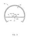
- FIG. 2is a cross-sectional view of the LED tube lamp of FIG. 1 , taken along line II-II.
- FIG. 3is a schematic, cross-sectional view showing a cover of the LED tube lamp of FIG. 1 .
- FIG. 4is a schematic, cross-sectional view showing light beams passing through the cover of the LED tube lamp of FIG. 1 .
- FIG. 5is a diagram showing the radiation patterns of the LED tube lamp of FIG. 1 and a typical fluorescent tube lamp.
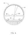
- FIG. 6is an assembled, cross-sectional view of an LED tube lamp in accordance with a second embodiment.
- the LED tube lamp 100includes a heat sink 10 , a cover 20 , and a pair of connectors 30 .
- the connectors 30are arranged at opposite ends of the LED tube lamp 100 and are used to connect to a coupling connector (not shown), thus electrically connecting the LED tube lamp 100 to a power source.
- the LED tube lamp 100further includes an LED substrate 40 that is mounted on the heat sink 10 , and electrically connected to the connector 30 .
- a number of LEDs 41are arranged on the LED substrate 40 .
- the LEDs 41can be chosen for having a large light divergence angle, high luminance, and/or colored according to actual requirements.
- the heat sink 10has an elongated structure and is made of metal with good heat conductivity, such as copper or aluminum. In another embodiment, the heat sink 10 can be made of ceramic.
- the heat sink 10includes a number of cooling fins 11 arranged on the bottom surface of the heat sink 10 to increase the heat dissipation area.
- a recess 12is defined in the top surface of the heat sink 10 for receiving the LED substrate 40 .
- a heat-conductive medium(not shown) can be arranged between the LED substrate 40 and the inner surface of the recess 12 , for transferring the heat generated by the LEDs 41 from the LED substrate 40 to the cooling fins 11 .
- the heat-conductive mediumcan be thermal conductive glue or heat-conductive plate.
- the LED substrate 40is fixed on the heat sink 10 with screws (not shown).
- the heat sink 10further includes connecting portions 13 .
- the connecting portions 13are grooves.
- the cover 20includes two projecting members 23 extending inwardly from the opposite ends of the cover 20 .
- the projecting members 23are respectively received in the connecting portions 13 , thus fixing the cover 20 to the heat sink 10 .
- the cover 20has an elongated structure and is arc-shaped in cross section.
- the cover 20includes a first cover 21 and a second cover 22 , the first cover 21 is closer to the LED substrate 40 than the second cover 22 .
- the second cover 22has an arc-shaped cross section, with two ends fixed to opposite ends of the first cover 21 .
- the cover 20faces the LED substrate 40 , and the light beams emitted from the LEDs 41 pass through the first cover 21 , then pass through the second cover 22 to spread out.
- the first cover 21is transparent and may be made of plastic or glass, such as polymethyl methacrylate (PMMA).
- the first cover 21includes an optical lens 24 defined on the surface of the first cover 21 .
- a row of the LEDs 41are arranged in the middle of the LED substrate 40
- the lens 24is arranged above the LEDs 41 directly and has an elongated structure.
- the lens 24includes a concave lens 241 and two reflective lenses 242 arranged on both sides of the concave lens 241 .
- two or more rows of the LEDs 41can be arranged on the LED substrate 40
- optical lenses 24can be designed on the surface of the first cover 21 corresponding to the two or more rows of the LEDs 41 .
- the concave lens 241is a plano concave lens including a planar face 2411 and a concave face 2422 .
- the light beams from the LEDs 41enter the concave lens 241 from its planar face 2411 and exit from its concave face 2422 .
- the reflective lenses 242are total reflection prisms arranged on both sides of the concave lens 241 .
- the top inner surface of the reflective lenses 242is the total reflection face.
- the light beams from the LEDs 41enter the reflective lenses 242 from a bottom surface and are reflected by the top inner surface.
- the reflective lenses 242can be a lens with a total reflection face, such as a lens with a high reflective film coated on its top surface.
- the lens 24further includes scatter layers 243 arranged on lateral surface of the reflective lenses 242 .
- the scatter layers 243can be a film of scatter material coated on the surface of the reflective lenses 242 .
- the light beams emitting from the LEDs 41 in a forward direction or in an approximate forward directionenter the concave lens 241 and are refracted by the concave lens 241 , which enlarges the divergence angle.
- the light beams emitting from the LEDs 41 in a lateral directionenter the reflective lenses 242 and are reflected by the reflective lenses 242 , which changes the direction of the light beams.
- the light beams reflected by the reflective lenses 242enter the scatter layers 243 and are diffused by the scatter layers 243 . After the light beams are refracted by the concave lens 241 and reflected by the reflective lenses 242 , the incident angle of the light beams travelling to the second cover 22 is greatly increased.
- the light divergence angle of the LED tube lamp 100is increased correspondingly.
- the light emitting angle of the light emitting diodes 42enlarges, particularly, the lateral lighting direction of the LED tube lamp 100 is improved thus the light beams become softer.
- the second cover 22can be made of transparent or translucent material mixed with light diffusion particles to improve the light scattering effect of the light.
- a scatter layer 25is arranged on the inner surface of the second cover 22 to scatter the light incident beams from the lens 24 , thus achieving a homogeneous illumination effect.
- the scatter layer 25can be a coating of scatter material coated on the inner/outer surface of the second cover 22 , or a film of scatter material arranged on the inner/outer surface of the second cover 22 .
- a plurality of accentuated portionssuch as protuberances and/or recesses can be defined on the inner/outer surface of the second cover 22 to scatter the light beams.
- the first region 51shows the radiation pattern of the LED tube lamp 100 in this embodiment, where the second region 52 shows the radiation pattern of a typical LED tube lamp.
- the light divergence angle of the LED tube lamp 100is maximized over that of the conventional LED tube lamp.
- the LED tube lamp 102is similar to the LED tube lamp 100 that is described above.
- the LED tube lamp 102includes a cover (not labeled) and a LED substrate (not labeled) including a number of LEDs 401 arranged on the LED substrate.
- the coverincludes a first cover 201 and a second cover 202 .
- the difference between the lamps 102 and 100is that the optical lens 204 defined on the surface of the first cover 201 is a concave lens.
- the light beams from the LEDs 401enter the optical lens 204 and are refracted, which enlarges the divergence angle.
- the light beamsare then refracted by the optical lens 204 and reach the second cover 202 and spread out. After the light beams are refracted by the optical lens 204 , the incident angle of the light beams travelling to the second cover 202 is increased, and the light divergence angle of the LED tube lamp 100 is increased correspondingly.
Landscapes
- Engineering & Computer Science (AREA)
- General Engineering & Computer Science (AREA)
- Physics & Mathematics (AREA)
- Microelectronics & Electronic Packaging (AREA)
- Optics & Photonics (AREA)
- Non-Portable Lighting Devices Or Systems Thereof (AREA)
Abstract
Description
1. Technical Field
The present disclosure relates to light emitting diode (LED) illuminating devices and, particularly, to an LED tube lamp.
2. Description of Related Art
Compared to traditional light sources, light emitting diodes (LEDs) have advantages, such as high luminous efficiency, low power consumption, and long service life. LED lights are widely used in many applications to replace typical fluorescent lamps and neon tube lamps.
Typical LED tube lamps usually include a cylindrical tube and an LED substrate. However, in order to increase the luminance, a type of LED array including a plurality of LEDs connected in series arranged on the LED substrate is used in LED tube lamps. But all the LEDs in the LED array emit light in the same direction. This kind of LED array will not increase light divergence angle of LED tube lamps.
Therefore, there is room for improvement in the art.
Many aspects of the embodiments can be better understood with reference to the following drawings. The components in the drawings are not necessarily drawn to scale, the emphasis instead being placed upon clearly illustrating the principles of the present disclosure. Moreover, in the drawings, like reference numerals designate corresponding parts throughout the several views, and all the views are schematic.
Embodiments of the present disclosure are now described in detail, with reference to the accompanying drawings.
Referring toFIG. 1 , anLED tube lamp 100 according to a first embodiment is illustrated. TheLED tube lamp 100 includes aheat sink 10, acover 20, and a pair ofconnectors 30. Theconnectors 30 are arranged at opposite ends of theLED tube lamp 100 and are used to connect to a coupling connector (not shown), thus electrically connecting theLED tube lamp 100 to a power source.
Referring toFIG. 2 , theLED tube lamp 100 further includes anLED substrate 40 that is mounted on theheat sink 10, and electrically connected to theconnector 30. A number ofLEDs 41 are arranged on theLED substrate 40. TheLEDs 41 can be chosen for having a large light divergence angle, high luminance, and/or colored according to actual requirements.
Theheat sink 10 has an elongated structure and is made of metal with good heat conductivity, such as copper or aluminum. In another embodiment, theheat sink 10 can be made of ceramic. Theheat sink 10 includes a number ofcooling fins 11 arranged on the bottom surface of theheat sink 10 to increase the heat dissipation area. Arecess 12 is defined in the top surface of theheat sink 10 for receiving theLED substrate 40. In this embodiment, a heat-conductive medium (not shown) can be arranged between theLED substrate 40 and the inner surface of therecess 12, for transferring the heat generated by theLEDs 41 from theLED substrate 40 to thecooling fins 11. In this embodiment, the heat-conductive medium can be thermal conductive glue or heat-conductive plate. In this embodiment, theLED substrate 40 is fixed on theheat sink 10 with screws (not shown).
Theheat sink 10 further includes connectingportions 13. In the embodiment, the connectingportions 13 are grooves. Thecover 20 includes two projectingmembers 23 extending inwardly from the opposite ends of thecover 20. The projectingmembers 23 are respectively received in the connectingportions 13, thus fixing thecover 20 to theheat sink 10. Thecover 20 has an elongated structure and is arc-shaped in cross section.
Thecover 20 includes afirst cover 21 and asecond cover 22, thefirst cover 21 is closer to theLED substrate 40 than thesecond cover 22. Thesecond cover 22 has an arc-shaped cross section, with two ends fixed to opposite ends of thefirst cover 21. Thecover 20 faces theLED substrate 40, and the light beams emitted from theLEDs 41 pass through thefirst cover 21, then pass through thesecond cover 22 to spread out.
Referring toFIG. 3 , thefirst cover 21 is transparent and may be made of plastic or glass, such as polymethyl methacrylate (PMMA). Thefirst cover 21 includes anoptical lens 24 defined on the surface of thefirst cover 21. In the first embodiment, a row of theLEDs 41 are arranged in the middle of theLED substrate 40, thelens 24 is arranged above theLEDs 41 directly and has an elongated structure. Thelens 24 includes aconcave lens 241 and two reflective lenses242 arranged on both sides of theconcave lens 241. In other embodiments, two or more rows of theLEDs 41 can be arranged on theLED substrate 40, andoptical lenses 24 can be designed on the surface of thefirst cover 21 corresponding to the two or more rows of theLEDs 41.
In the first embodiment, theconcave lens 241 is a plano concave lens including aplanar face 2411 and a concave face2422. The light beams from theLEDs 41 enter theconcave lens 241 from itsplanar face 2411 and exit from its concave face2422. The reflective lenses242 are total reflection prisms arranged on both sides of theconcave lens 241. The top inner surface of the reflective lenses242 is the total reflection face. The light beams from theLEDs 41 enter the reflective lenses242 from a bottom surface and are reflected by the top inner surface. In another embodiment, the reflective lenses242 can be a lens with a total reflection face, such as a lens with a high reflective film coated on its top surface. Thelens 24 further includesscatter layers 243 arranged on lateral surface of the reflective lenses242. Thescatter layers 243 can be a film of scatter material coated on the surface of the reflective lenses242.
Referring toFIG. 4 , the light beams emitting from theLEDs 41 in a forward direction or in an approximate forward direction enter theconcave lens 241 and are refracted by theconcave lens 241, which enlarges the divergence angle. The light beams emitting from theLEDs 41 in a lateral direction enter the reflective lenses242 and are reflected by the reflective lenses242, which changes the direction of the light beams. The light beams reflected by the reflective lenses242 enter thescatter layers 243 and are diffused by thescatter layers 243. After the light beams are refracted by theconcave lens 241 and reflected by the reflective lenses242, the incident angle of the light beams travelling to thesecond cover 22 is greatly increased. As a result, the light divergence angle of theLED tube lamp 100 is increased correspondingly. In this way, the light emitting angle of the light emitting diodes42 enlarges, particularly, the lateral lighting direction of theLED tube lamp 100 is improved thus the light beams become softer.
Thesecond cover 22 can be made of transparent or translucent material mixed with light diffusion particles to improve the light scattering effect of the light. In this embodiment, ascatter layer 25 is arranged on the inner surface of thesecond cover 22 to scatter the light incident beams from thelens 24, thus achieving a homogeneous illumination effect. Thescatter layer 25 can be a coating of scatter material coated on the inner/outer surface of thesecond cover 22, or a film of scatter material arranged on the inner/outer surface of thesecond cover 22. In other embodiments, a plurality of accentuated portions such as protuberances and/or recesses can be defined on the inner/outer surface of thesecond cover 22 to scatter the light beams.
Referring toFIG. 5 , as can be seen in the diagram, thefirst region 51 shows the radiation pattern of theLED tube lamp 100 in this embodiment, where thesecond region 52 shows the radiation pattern of a typical LED tube lamp. The light divergence angle of theLED tube lamp 100 is maximized over that of the conventional LED tube lamp.
Referring toFIG. 6 , anLED tube lamp 102 according to a second embodiment is illustrated. TheLED tube lamp 102 is similar to theLED tube lamp 100 that is described above. TheLED tube lamp 102 includes a cover (not labeled) and a LED substrate (not labeled) including a number ofLEDs 401 arranged on the LED substrate. The cover includes afirst cover 201 and asecond cover 202. The difference between thelamps optical lens 204 defined on the surface of thefirst cover 201 is a concave lens. The light beams from theLEDs 401 enter theoptical lens 204 and are refracted, which enlarges the divergence angle. The light beams are then refracted by theoptical lens 204 and reach thesecond cover 202 and spread out. After the light beams are refracted by theoptical lens 204, the incident angle of the light beams travelling to thesecond cover 202 is increased, and the light divergence angle of theLED tube lamp 100 is increased correspondingly.
It is to be understood, however, that even though numerous characteristics and advantages of the present disclosure have been set forth in the foregoing description, together with details of the structure and function of the present disclosure, the present disclosure is illustrative only, and changes may be made in detail, especially in matters of shape, size, and arrangement of parts within the principles of the present disclosure to the full extent indicated by the broad general meaning of the terms in which the appended claims are expressed.
Claims (20)
1. An LED tube lamp, comprising:
a heat sink;
an LED substrate mounted on the heat sink and comprising a plurality of LEDs;
a cover fixed to the heat sink and shielding the plurality of LEDs;
wherein the cover comprises a first cover and a second cover, the first cover is closer to the LED substrate than the second cover, at least one optical lens is arranged on the first cover, each of the at least one optical lens comprises a concave lens, reflective lenses arranged on both sides of the concave lens and scatter layers arranged on lateral surface of the reflective lenses, the concave lens is a plano concave lens comprising a planar surface and a concave surface, the light beams enter the concave lens from the planar face and exit from the concave face, the concave lens are configured for refracting light beams from the LEDs in a forward direction or in an approximate forward direction, the reflective lenses are configured for reflecting light beams from the LEDs in a lateral direction.
2. The LED tube lamp according toclaim 1 , wherein a row of the LEDs are defined in the middle of the LED substrate, the number of the at least one optical lens is one, and the optical lens is arranged above the LEDs directly.
3. The LED tube lamp according toclaim 1 , wherein the reflective lenses are total reflection prism arranged on both sides of the concave lens.
4. The LED tube lamp according toclaim 1 , wherein the second cover is made of transparent or translucent material mixed with light diffusion particles.
5. The LED tube lamp according toclaim 1 , wherein the second cover further comprises a scatter layer arranged on the surface of the second cover.
6. The LED tube lamp according toclaim 5 , wherein the scatter layer is a coating of scatter material coated on the inner/outer surface of the second cover.
7. The LED tube lamp according toclaim 5 , wherein the scatter layer is a film of scatter material arranged on the inner/outer surface of the second cover.
8. The LED tube lamp according toclaim 1 , wherein the heat sink comprises two grooves, the cover comprises two projecting members extending inwardly from the opposite ends of the cover, the two projecting members are respectively received in the grooves.
9. The LED tube lamp according toclaim 1 , where a recess is defined in the top surface of the heat sink for receiving the LED substrate.
10. The LED tube lamp according toclaim 1 , wherein a plurality of cooling fins are arranged on the bottom surface of the heat sink.
11. An LED tube lamp, comprising:
a heat sink;
an LED substrate mounted on the heat sink and comprising a plurality of LEDs;
a cover fixed to the heat sink and shielding the plurality of LEDs;
wherein the cover comprises a first cover and a second cover, the first cover is closer to the LED substrate than the second cover, at least one optical lens is arranged on the first cover, each of the at least one optical lens comprises a concave lens, reflective lenses arranged on both sides of the concave lens and scatter layers arranged on lateral surface of the reflective lenses, a top inner surface of the reflective lenses is a total reflection face, the light beams from the LEDs enter the reflective lenses from a bottom surface and are reflected by the top inner surface, the concave lens are configured for refracting light beams from the LEDs in a forward direction or in an approximate forward direction, the reflective lenses are configured for reflecting light beams from the LEDs in a lateral direction.
12. The LED tube lamp according toclaim 11 , wherein a row of the LEDs are defined in the middle of the LED substrate, the number of the at least one optical lens is one, and the optical lens is arranged above the LEDs directly.
13. The LED tube lamp according toclaim 11 , wherein the reflective lenses are total reflection prism arranged on both sides of the concave lens.
14. The LED tube lamp according toclaim 11 , wherein the second cover is made of transparent or translucent material mixed with light diffusion particles.
15. The LED tube lamp according toclaim 11 , wherein the second cover further comprises a scatter layer arranged on the surface of the second cover.
16. The LED tube lamp according toclaim 15 , wherein the scatter layer is a coating of scatter material coated on the inner/outer surface of the second cover.
17. The LED tube lamp according toclaim 15 , wherein the scatter layer is a film of scatter material arranged on the inner/outer surface of the second cover.
18. The LED tube lamp according toclaim 11 , wherein the heat sink comprises two grooves, the cover comprises two projecting members extending inwardly from the opposite ends of the cover, the two projecting members are respectively received in the grooves.
19. The LED tube lamp according toclaim 11 , where a recess is defined in the top surface of the heat sink for receiving the LED substrate.
20. The LED tube lamp according toclaim 11 , wherein a plurality of cooling fins are arranged on the bottom surface of the heat sink.
Applications Claiming Priority (3)
| Application Number | Priority Date | Filing Date | Title |
|---|---|---|---|
| CN201010523197 | 2010-10-28 | ||
| CN2010105231979ACN101975345B (en) | 2010-10-28 | 2010-10-28 | LED (Light Emitting Diode) fluorescent lamp |
| CN201010523197.9 | 2010-10-28 |
Publications (2)
| Publication Number | Publication Date |
|---|---|
| US20120106144A1 US20120106144A1 (en) | 2012-05-03 |
| US8998448B2true US8998448B2 (en) | 2015-04-07 |
Family
ID=43575248
Family Applications (1)
| Application Number | Title | Priority Date | Filing Date |
|---|---|---|---|
| US13/091,135Expired - Fee RelatedUS8998448B2 (en) | 2010-10-28 | 2011-04-21 | LED tube lamp |
Country Status (2)
| Country | Link |
|---|---|
| US (1) | US8998448B2 (en) |
| CN (1) | CN101975345B (en) |
Cited By (17)
| Publication number | Priority date | Publication date | Assignee | Title |
|---|---|---|---|---|
| US9353916B2 (en) | 2012-10-03 | 2016-05-31 | Lighting Science Group Corporation | Elongated LED luminaire and associated methods |
| US9581756B2 (en) | 2009-10-05 | 2017-02-28 | Lighting Science Group Corporation | Light guide for low profile luminaire |
| US9693414B2 (en) | 2011-12-05 | 2017-06-27 | Biological Illumination, Llc | LED lamp for producing biologically-adjusted light |
| US20180135812A1 (en)* | 2015-05-18 | 2018-05-17 | Philips Lighting Holding B.V. | Tubular light emitting device |
| US10317021B2 (en)* | 2017-02-24 | 2019-06-11 | Whiteoptics Llc | Linear light emitting diode luminaires |
| US20200158299A1 (en)* | 2017-03-09 | 2020-05-21 | Lilibrand Llc | Fixtures and lighting accessories for lighting devices |
| US10788170B1 (en)* | 2019-11-19 | 2020-09-29 | Elemental LED, Inc. | Optical systems for linear lighting |
| US10920940B1 (en) | 2019-11-19 | 2021-02-16 | Elemental LED, Inc. | Optical system for linear lighting |
| US11002425B1 (en) | 2019-03-08 | 2021-05-11 | Abl Ip Holding Llc | Optical cover with faceted surface |
| US11022279B2 (en) | 2016-03-08 | 2021-06-01 | Ecosense Lighting Inc. | Lighting system with lens assembly |
| US11028980B2 (en) | 2013-10-30 | 2021-06-08 | Ecosense Lighting Inc. | Flexible strip lighting apparatus and methods |
| US11041609B2 (en) | 2018-05-01 | 2021-06-22 | Ecosense Lighting Inc. | Lighting systems and devices with central silicone module |
| US11296057B2 (en) | 2017-01-27 | 2022-04-05 | EcoSense Lighting, Inc. | Lighting systems with high color rendering index and uniform planar illumination |
| US11346526B1 (en) | 2019-03-08 | 2022-05-31 | Abl Ip Holding Llc | Area optical cover with faceted surface |
| US11353200B2 (en) | 2018-12-17 | 2022-06-07 | Korrus, Inc. | Strip lighting system for direct input of high voltage driving power |
| US11821597B1 (en)* | 2022-06-30 | 2023-11-21 | Elemental LED, Inc. | Linear luminaire |
| US12388056B1 (en) | 2017-01-27 | 2025-08-12 | Korrus, Inc. | Linear lighting systems and processes |
Families Citing this family (69)
| Publication number | Priority date | Publication date | Assignee | Title |
|---|---|---|---|---|
| US7049761B2 (en) | 2000-02-11 | 2006-05-23 | Altair Engineering, Inc. | Light tube and power supply circuit |
| US20080029720A1 (en) | 2006-08-03 | 2008-02-07 | Intematix Corporation | LED lighting arrangement including light emitting phosphor |
| US8118447B2 (en) | 2007-12-20 | 2012-02-21 | Altair Engineering, Inc. | LED lighting apparatus with swivel connection |
| US8360599B2 (en) | 2008-05-23 | 2013-01-29 | Ilumisys, Inc. | Electric shock resistant L.E.D. based light |
| WO2016086901A2 (en)* | 2014-12-05 | 2016-06-09 | Jiaxing Super Lighting Electric Appliance Co., Ltd | Led tube lamp |
| US8214084B2 (en) | 2008-10-24 | 2012-07-03 | Ilumisys, Inc. | Integration of LED lighting with building controls |
| US8324817B2 (en) | 2008-10-24 | 2012-12-04 | Ilumisys, Inc. | Light and light sensor |
| US7938562B2 (en) | 2008-10-24 | 2011-05-10 | Altair Engineering, Inc. | Lighting including integral communication apparatus |
| US8653984B2 (en) | 2008-10-24 | 2014-02-18 | Ilumisys, Inc. | Integration of LED lighting control with emergency notification systems |
| US8901823B2 (en) | 2008-10-24 | 2014-12-02 | Ilumisys, Inc. | Light and light sensor |
| US8864340B2 (en) | 2009-10-05 | 2014-10-21 | Lighting Science Group Corporation | Low profile light having concave reflector and associated methods |
| US9157581B2 (en) | 2009-10-05 | 2015-10-13 | Lighting Science Group Corporation | Low profile luminaire with light guide and associated systems and methods |
| US9028091B2 (en) | 2009-10-05 | 2015-05-12 | Lighting Science Group Corporation | Low profile light having elongated reflector and associated methods |
| CN101788111B (en)* | 2010-01-15 | 2012-07-04 | 上海开腾信号设备有限公司 | Quasi-fluorescence LED illumination monomer and application thereof |
| CA2792940A1 (en) | 2010-03-26 | 2011-09-19 | Ilumisys, Inc. | Led light with thermoelectric generator |
| US8540401B2 (en) | 2010-03-26 | 2013-09-24 | Ilumisys, Inc. | LED bulb with internal heat dissipating structures |
| US9827439B2 (en) | 2010-07-23 | 2017-11-28 | Biological Illumination, Llc | System for dynamically adjusting circadian rhythm responsive to scheduled events and associated methods |
| US9532423B2 (en) | 2010-07-23 | 2016-12-27 | Lighting Science Group Corporation | System and methods for operating a lighting device |
| US8760370B2 (en) | 2011-05-15 | 2014-06-24 | Lighting Science Group Corporation | System for generating non-homogenous light and associated methods |
| US9024536B2 (en) | 2011-12-05 | 2015-05-05 | Biological Illumination, Llc | Tunable LED lamp for producing biologically-adjusted light and associated methods |
| US8841864B2 (en) | 2011-12-05 | 2014-09-23 | Biological Illumination, Llc | Tunable LED lamp for producing biologically-adjusted light |
| US8686641B2 (en) | 2011-12-05 | 2014-04-01 | Biological Illumination, Llc | Tunable LED lamp for producing biologically-adjusted light |
| US8465167B2 (en) | 2011-09-16 | 2013-06-18 | Lighting Science Group Corporation | Color conversion occlusion and associated methods |
| US9546765B2 (en) | 2010-10-05 | 2017-01-17 | Intematix Corporation | Diffuser component having scattering particles |
| EP2633227B1 (en) | 2010-10-29 | 2018-08-29 | iLumisys, Inc. | Mechanisms for reducing risk of shock during installation of light tube |
| US9360202B2 (en) | 2011-05-13 | 2016-06-07 | Lighting Science Group Corporation | System for actively cooling an LED filament and associated methods |
| US9151482B2 (en) | 2011-05-13 | 2015-10-06 | Lighting Science Group Corporation | Sealed electrical device with cooling system |
| TWI442000B (en)* | 2011-07-19 | 2014-06-21 | Wistron Corp | Light bar structure and light source device |
| US9072171B2 (en) | 2011-08-24 | 2015-06-30 | Ilumisys, Inc. | Circuit board mount for LED light |
| US9194541B2 (en)* | 2011-11-10 | 2015-11-24 | Epistar Corporation | Illumination apparatus |
| US8963450B2 (en) | 2011-12-05 | 2015-02-24 | Biological Illumination, Llc | Adaptable biologically-adjusted indirect lighting device and associated methods |
| US9220202B2 (en) | 2011-12-05 | 2015-12-29 | Biological Illumination, Llc | Lighting system to control the circadian rhythm of agricultural products and associated methods |
| US9289574B2 (en) | 2011-12-05 | 2016-03-22 | Biological Illumination, Llc | Three-channel tuned LED lamp for producing biologically-adjusted light |
| US9184518B2 (en) | 2012-03-02 | 2015-11-10 | Ilumisys, Inc. | Electrical connector header for an LED-based light |
| WO2013147504A1 (en)* | 2012-03-30 | 2013-10-03 | Samsung Electronics Co., Ltd. | Lighting device and method for manufacturing the same |
| US9163794B2 (en) | 2012-07-06 | 2015-10-20 | Ilumisys, Inc. | Power supply assembly for LED-based light tube |
| US9271367B2 (en) | 2012-07-09 | 2016-02-23 | Ilumisys, Inc. | System and method for controlling operation of an LED-based light |
| MX2012012917A (en)* | 2012-11-06 | 2014-05-21 | Luis Gerardo Aviña Silva | Tubular led lamp. |
| WO2014087278A1 (en) | 2012-12-03 | 2014-06-12 | Koninklijke Philips N.V. | Light emitting arrangement using light guides. |
| US20140185269A1 (en) | 2012-12-28 | 2014-07-03 | Intermatix Corporation | Solid-state lamps utilizing photoluminescence wavelength conversion components |
| US9347655B2 (en) | 2013-03-11 | 2016-05-24 | Lighting Science Group Corporation | Rotatable lighting device |
| JP2014175207A (en)* | 2013-03-11 | 2014-09-22 | Ricoh Co Ltd | Straight tube type led lamp and illumination device |
| US9459397B2 (en) | 2013-03-12 | 2016-10-04 | Lighting Science Group Corporation | Edge lit lighting device |
| US9285084B2 (en) | 2013-03-14 | 2016-03-15 | Ilumisys, Inc. | Diffusers for LED-based lights |
| WO2014151263A1 (en) | 2013-03-15 | 2014-09-25 | Intematix Corporation | Photoluminescence wavelength conversion components |
| WO2014195144A1 (en)* | 2013-06-03 | 2014-12-11 | Koninklijke Philips N.V. | Tubular lighting device |
| KR102050055B1 (en)* | 2013-06-05 | 2019-11-28 | 엘지이노텍 주식회사 | Illumination apparatus |
| TWI519735B (en) | 2013-09-02 | 2016-02-01 | 雷盟光電股份有限公司 | Led lamp with heat dissipating structures |
| CN104421708B (en)* | 2013-09-11 | 2017-09-05 | 雷盟光电股份有限公司 | LED lamp with heat radiation structure |
| US9267650B2 (en) | 2013-10-09 | 2016-02-23 | Ilumisys, Inc. | Lens for an LED-based light |
| TW201518644A (en)* | 2013-11-04 | 2015-05-16 | Lextar Electronics Corp | Light tube structure |
| US9429294B2 (en) | 2013-11-11 | 2016-08-30 | Lighting Science Group Corporation | System for directional control of light and associated methods |
| US10161570B2 (en)* | 2014-01-22 | 2018-12-25 | Philips Lighting Holding B.V. | Lighting device and luminaire |
| CN106063381A (en) | 2014-01-22 | 2016-10-26 | 伊卢米斯公司 | LED-based light with addressed LEDs |
| US20150252965A1 (en)* | 2014-03-07 | 2015-09-10 | Intematix Corporation | Solid-state linear lighting arrangements including light emitting phosphor |
| US9510400B2 (en) | 2014-05-13 | 2016-11-29 | Ilumisys, Inc. | User input systems for an LED-based light |
| CN105090880B (en)* | 2014-05-23 | 2018-07-31 | 重庆四联光电科技有限公司 | emergency lighting fluorescent lamp and its manufacturing method |
| DE102014217324A1 (en)* | 2014-08-29 | 2016-03-03 | Osram Gmbh | Lighting device with a cavity |
| US20160076706A1 (en)* | 2014-09-17 | 2016-03-17 | Ge Lighting Solutions, Llc. | Method and system for led lamp incorporating internal optics for specific light distribution |
| CN104595773A (en)* | 2015-02-06 | 2015-05-06 | 开发晶照明(厦门)有限公司 | LED (Light-Emitting Diode) lamp tube with external light source |
| US10161568B2 (en) | 2015-06-01 | 2018-12-25 | Ilumisys, Inc. | LED-based light with canted outer walls |
| EP3196550B1 (en)* | 2016-01-20 | 2018-10-24 | OSRAM GmbH | A method of producing lighting devices and corresponding lighting device |
| JP2018056105A (en)* | 2016-09-29 | 2018-04-05 | 株式会社アブラム | Light-emitting diode type lighting device |
| CN111396799A (en)* | 2017-01-05 | 2020-07-10 | 光宝电子(广州)有限公司 | Lighting device |
| US10845013B2 (en) | 2018-10-03 | 2020-11-24 | Vista Manufacturing Inc | Flexible light assembly |
| CN209431123U (en)* | 2018-12-20 | 2019-09-24 | 漳州立达信光电子科技有限公司 | A kind of LED straight lamp |
| US11085592B1 (en)* | 2020-06-29 | 2021-08-10 | Xiamen Leedarson Lighting Co. Ltd. | LED light tube |
| US11585499B2 (en)* | 2020-09-07 | 2023-02-21 | Xiamen Eco Lighting Co. Ltd. | Lighting apparatus |
| CN115949893A (en)* | 2022-11-24 | 2023-04-11 | 厦门普为光电科技有限公司 | Lighting device with prism grid microstructure |
Citations (19)
| Publication number | Priority date | Publication date | Assignee | Title |
|---|---|---|---|---|
| CN1811548A (en) | 2005-01-26 | 2006-08-02 | 晶元光电股份有限公司 | A light emitting diode light source |
| US7159997B2 (en)* | 2004-12-30 | 2007-01-09 | Lo Lighting | Linear lighting apparatus with increased light-transmission efficiency |
| TWM331075U (en) | 2007-08-24 | 2008-04-21 | Insight Electronic Group Inc | LED lighting device |
| US20090219713A1 (en)* | 2008-03-02 | 2009-09-03 | Altair Engineering, Inc. | Lens and heatsink assembly for a led light tube |
| TWI315430B (en) | 2005-08-08 | 2009-10-01 | Coretronic Corp | Light emitting device and plane light source module |
| US7611260B1 (en)* | 2008-07-02 | 2009-11-03 | Cpumate Inc. | Protecting cover and LED lamp tube having the same |
| US7618157B1 (en)* | 2008-06-25 | 2009-11-17 | Osram Sylvania Inc. | Tubular blue LED lamp with remote phosphor |
| US20090290334A1 (en)* | 2008-05-23 | 2009-11-26 | Altair Engineering, Inc. | Electric shock resistant l.e.d. based light |
| US7654703B2 (en)* | 2004-01-28 | 2010-02-02 | Koninklijke Philips Electronics, N.V. | Directly viewable luminaire |
| US7658509B2 (en)* | 2006-11-14 | 2010-02-09 | Honeywell International Inc. | Solid-state strip lighting system for assembly efficiency and variable beam angle with integral heatsink |
| US20100110679A1 (en)* | 2008-11-04 | 2010-05-06 | Advanced Optoelectronic Technology Inc. | Light emitting diode light module and optical engine thereof |
| CN101788111A (en) | 2010-01-15 | 2010-07-28 | 上海开腾信号设备有限公司 | Quasi-fluorescence LED illumination monomer and application thereof |
| US20100201911A1 (en) | 2009-02-12 | 2010-08-12 | Panasonic Corporation | Illuminating lens, lighting device, surface light source, and liquid-crystal display apparatus |
| WO2010092632A1 (en) | 2009-02-12 | 2010-08-19 | パナソニック株式会社 | Lighting lens, light emitting device, area light source, and liquid cristal display device |
| TWM389811U (en) | 2010-05-12 | 2010-10-01 | Ledtech Electronics Corp | Illumination structure and lamp tube structure for generating plural specifically directional light sources |
| US20120025235A1 (en)* | 2010-07-29 | 2012-02-02 | Cree, Inc. | Lighting devices that comprise one or more solid state light emitters |
| US8309969B2 (en)* | 2008-11-20 | 2012-11-13 | Toyoda Gosei Co., Ltd. | Light emitting device and method of making same |
| US8382314B2 (en)* | 2010-05-12 | 2013-02-26 | Fred OU | LED channel |
| US8556454B2 (en)* | 2008-11-04 | 2013-10-15 | Everlight Electronics Co., Ltd. | Light tube |
- 2010
- 2010-10-28CNCN2010105231979Apatent/CN101975345B/ennot_activeExpired - Fee Related
- 2011
- 2011-04-21USUS13/091,135patent/US8998448B2/ennot_activeExpired - Fee Related
Patent Citations (19)
| Publication number | Priority date | Publication date | Assignee | Title |
|---|---|---|---|---|
| US7654703B2 (en)* | 2004-01-28 | 2010-02-02 | Koninklijke Philips Electronics, N.V. | Directly viewable luminaire |
| US7159997B2 (en)* | 2004-12-30 | 2007-01-09 | Lo Lighting | Linear lighting apparatus with increased light-transmission efficiency |
| CN1811548A (en) | 2005-01-26 | 2006-08-02 | 晶元光电股份有限公司 | A light emitting diode light source |
| TWI315430B (en) | 2005-08-08 | 2009-10-01 | Coretronic Corp | Light emitting device and plane light source module |
| US7658509B2 (en)* | 2006-11-14 | 2010-02-09 | Honeywell International Inc. | Solid-state strip lighting system for assembly efficiency and variable beam angle with integral heatsink |
| TWM331075U (en) | 2007-08-24 | 2008-04-21 | Insight Electronic Group Inc | LED lighting device |
| US20090219713A1 (en)* | 2008-03-02 | 2009-09-03 | Altair Engineering, Inc. | Lens and heatsink assembly for a led light tube |
| US20090290334A1 (en)* | 2008-05-23 | 2009-11-26 | Altair Engineering, Inc. | Electric shock resistant l.e.d. based light |
| US7618157B1 (en)* | 2008-06-25 | 2009-11-17 | Osram Sylvania Inc. | Tubular blue LED lamp with remote phosphor |
| US7611260B1 (en)* | 2008-07-02 | 2009-11-03 | Cpumate Inc. | Protecting cover and LED lamp tube having the same |
| US20100110679A1 (en)* | 2008-11-04 | 2010-05-06 | Advanced Optoelectronic Technology Inc. | Light emitting diode light module and optical engine thereof |
| US8556454B2 (en)* | 2008-11-04 | 2013-10-15 | Everlight Electronics Co., Ltd. | Light tube |
| US8309969B2 (en)* | 2008-11-20 | 2012-11-13 | Toyoda Gosei Co., Ltd. | Light emitting device and method of making same |
| US20100201911A1 (en) | 2009-02-12 | 2010-08-12 | Panasonic Corporation | Illuminating lens, lighting device, surface light source, and liquid-crystal display apparatus |
| WO2010092632A1 (en) | 2009-02-12 | 2010-08-19 | パナソニック株式会社 | Lighting lens, light emitting device, area light source, and liquid cristal display device |
| CN101788111A (en) | 2010-01-15 | 2010-07-28 | 上海开腾信号设备有限公司 | Quasi-fluorescence LED illumination monomer and application thereof |
| TWM389811U (en) | 2010-05-12 | 2010-10-01 | Ledtech Electronics Corp | Illumination structure and lamp tube structure for generating plural specifically directional light sources |
| US8382314B2 (en)* | 2010-05-12 | 2013-02-26 | Fred OU | LED channel |
| US20120025235A1 (en)* | 2010-07-29 | 2012-02-02 | Cree, Inc. | Lighting devices that comprise one or more solid state light emitters |
Cited By (36)
| Publication number | Priority date | Publication date | Assignee | Title |
|---|---|---|---|---|
| US9581756B2 (en) | 2009-10-05 | 2017-02-28 | Lighting Science Group Corporation | Light guide for low profile luminaire |
| US9693414B2 (en) | 2011-12-05 | 2017-06-27 | Biological Illumination, Llc | LED lamp for producing biologically-adjusted light |
| US9913341B2 (en) | 2011-12-05 | 2018-03-06 | Biological Illumination, Llc | LED lamp for producing biologically-adjusted light including a cyan LED |
| US9353916B2 (en) | 2012-10-03 | 2016-05-31 | Lighting Science Group Corporation | Elongated LED luminaire and associated methods |
| US11028980B2 (en) | 2013-10-30 | 2021-06-08 | Ecosense Lighting Inc. | Flexible strip lighting apparatus and methods |
| US10690297B2 (en)* | 2015-05-18 | 2020-06-23 | Signify Holding B.V. | Tubular light emitting device |
| US20180135812A1 (en)* | 2015-05-18 | 2018-05-17 | Philips Lighting Holding B.V. | Tubular light emitting device |
| US11359796B2 (en) | 2016-03-08 | 2022-06-14 | Korrus, Inc. | Lighting system with lens assembly |
| US11512838B2 (en) | 2016-03-08 | 2022-11-29 | Korrus, Inc. | Lighting system with lens assembly |
| US12129990B2 (en) | 2016-03-08 | 2024-10-29 | Korrus, Inc. | Lighting system with lens assembly |
| US11060702B2 (en) | 2016-03-08 | 2021-07-13 | Ecosense Lighting Inc. | Lighting system with lens assembly |
| US11022279B2 (en) | 2016-03-08 | 2021-06-01 | Ecosense Lighting Inc. | Lighting system with lens assembly |
| US11867382B2 (en) | 2016-03-08 | 2024-01-09 | Korrus, Inc. | Lighting system with lens assembly |
| US11296057B2 (en) | 2017-01-27 | 2022-04-05 | EcoSense Lighting, Inc. | Lighting systems with high color rendering index and uniform planar illumination |
| US11658163B2 (en) | 2017-01-27 | 2023-05-23 | Korrus, Inc. | Lighting systems with high color rendering index and uniform planar illumination |
| US12388056B1 (en) | 2017-01-27 | 2025-08-12 | Korrus, Inc. | Linear lighting systems and processes |
| US12062645B2 (en) | 2017-01-27 | 2024-08-13 | Korrus, Inc. | Lighting systems with high color rendering index and uniform planar illumination |
| US10655803B2 (en) | 2017-02-24 | 2020-05-19 | Abl Ip Holding Llc | Linear light emitting diode luminaires |
| US10883678B2 (en) | 2017-02-24 | 2021-01-05 | Abl Ip Holding Llc | Linear light emitting diode luminaires |
| US11162652B2 (en) | 2017-02-24 | 2021-11-02 | Abl Ip Holding Llc | Linear light emitting diode luminaires |
| US10317021B2 (en)* | 2017-02-24 | 2019-06-11 | Whiteoptics Llc | Linear light emitting diode luminaires |
| US10989372B2 (en)* | 2017-03-09 | 2021-04-27 | Ecosense Lighting Inc. | Fixtures and lighting accessories for lighting devices |
| US20200158299A1 (en)* | 2017-03-09 | 2020-05-21 | Lilibrand Llc | Fixtures and lighting accessories for lighting devices |
| US11339932B2 (en) | 2017-03-09 | 2022-05-24 | Korrus, Inc. | Fixtures and lighting accessories for lighting devices |
| US11578857B2 (en) | 2018-05-01 | 2023-02-14 | Korrus, Inc. | Lighting systems and devices with central silicone module |
| US11041609B2 (en) | 2018-05-01 | 2021-06-22 | Ecosense Lighting Inc. | Lighting systems and devices with central silicone module |
| US11353200B2 (en) | 2018-12-17 | 2022-06-07 | Korrus, Inc. | Strip lighting system for direct input of high voltage driving power |
| US11708966B2 (en) | 2018-12-17 | 2023-07-25 | Korrus, Inc. | Strip lighting system for direct input of high voltage driving power |
| US11346526B1 (en) | 2019-03-08 | 2022-05-31 | Abl Ip Holding Llc | Area optical cover with faceted surface |
| US11002425B1 (en) | 2019-03-08 | 2021-05-11 | Abl Ip Holding Llc | Optical cover with faceted surface |
| US12331922B2 (en) | 2019-03-08 | 2025-06-17 | Abl Ip Holding Llc | Area optical cover with faceted surface |
| US11125397B2 (en) | 2019-11-19 | 2021-09-21 | Elemental LED, Inc. | Optical system for linear lighting |
| US11054091B2 (en) | 2019-11-19 | 2021-07-06 | Elemental LED, Inc. | Optical systems for linear lighting |
| US10920940B1 (en) | 2019-11-19 | 2021-02-16 | Elemental LED, Inc. | Optical system for linear lighting |
| US10788170B1 (en)* | 2019-11-19 | 2020-09-29 | Elemental LED, Inc. | Optical systems for linear lighting |
| US11821597B1 (en)* | 2022-06-30 | 2023-11-21 | Elemental LED, Inc. | Linear luminaire |
Also Published As
| Publication number | Publication date |
|---|---|
| CN101975345A (en) | 2011-02-16 |
| CN101975345B (en) | 2013-05-08 |
| US20120106144A1 (en) | 2012-05-03 |
Similar Documents
| Publication | Publication Date | Title |
|---|---|---|
| US8998448B2 (en) | LED tube lamp | |
| US20110305024A1 (en) | Led tube lamp | |
| US20120155072A1 (en) | Led tube lamp | |
| US20120051039A1 (en) | Led tube lamp | |
| US8376579B2 (en) | LED lamp | |
| US9366410B2 (en) | Reverse total internal reflection features in linear profile for lighting applications | |
| US10323824B1 (en) | LED light fixture with light shaping features | |
| US8246199B2 (en) | LED illuminating device | |
| US8789993B2 (en) | Light-emitting device | |
| CN101457901B (en) | Light field adjustment device and lighting device using the light field adjustment device | |
| US20090279311A1 (en) | Illumination device | |
| JP4828590B2 (en) | LED lens for double-sided illumination, LED module, and LED double-sided illumination device using the same | |
| US20120020108A1 (en) | Led lighting device | |
| US20120020066A1 (en) | Led lighting device | |
| KR20100126915A (en) | Lens and lighting unit having same | |
| US20120106134A1 (en) | Led ceiling lamp | |
| CN101963327B (en) | Refection cover and lighting device | |
| CN103629568A (en) | light emitting device | |
| WO2018032463A1 (en) | Lens structure, and lamp, backlight module and display device using same | |
| US20100246173A1 (en) | Illumination device with light diffusion plate | |
| KR101804969B1 (en) | Lens module for led luminaire | |
| KR101661900B1 (en) | The two-sided illumination LED lenses and LED modules and LED two-sided illuminating systems which use this | |
| CN102045915A (en) | LED lighting device | |
| CN115419863A (en) | Uniform lighting lens and lamp thereof | |
| KR101113611B1 (en) | Lens for a lighting unit |
Legal Events
| Date | Code | Title | Description |
|---|---|---|---|
| AS | Assignment | Owner name:HON HAI PRECISION INDUSTRY CO., LTD., TAIWAN Free format text:ASSIGNMENT OF ASSIGNORS INTEREST;ASSIGNOR:CHANG, SHAO-HAN;REEL/FRAME:026160/0072 Effective date:20110418 | |
| STCF | Information on status: patent grant | Free format text:PATENTED CASE | |
| FEPP | Fee payment procedure | Free format text:MAINTENANCE FEE REMINDER MAILED (ORIGINAL EVENT CODE: REM.); ENTITY STATUS OF PATENT OWNER: LARGE ENTITY | |
| LAPS | Lapse for failure to pay maintenance fees | Free format text:PATENT EXPIRED FOR FAILURE TO PAY MAINTENANCE FEES (ORIGINAL EVENT CODE: EXP.); ENTITY STATUS OF PATENT OWNER: LARGE ENTITY | |
| STCH | Information on status: patent discontinuation | Free format text:PATENT EXPIRED DUE TO NONPAYMENT OF MAINTENANCE FEES UNDER 37 CFR 1.362 | |
| FP | Lapsed due to failure to pay maintenance fee | Effective date:20190407 |