US8997742B2 - Ergonomic and adjustable respiratory mask assembly with cushion - Google Patents
Ergonomic and adjustable respiratory mask assembly with cushionDownload PDFInfo
- Publication number
- US8997742B2 US8997742B2US10/390,682US39068203AUS8997742B2US 8997742 B2US8997742 B2US 8997742B2US 39068203 AUS39068203 AUS 39068203AUS 8997742 B2US8997742 B2US 8997742B2
- Authority
- US
- United States
- Prior art keywords
- cushion
- patient
- mask assembly
- respiratory mask
- assembly according
- Prior art date
- Legal status (The legal status is an assumption and is not a legal conclusion. Google has not performed a legal analysis and makes no representation as to the accuracy of the status listed.)
- Active, expires
Links
Images


Classifications
- A—HUMAN NECESSITIES
- A61—MEDICAL OR VETERINARY SCIENCE; HYGIENE
- A61M—DEVICES FOR INTRODUCING MEDIA INTO, OR ONTO, THE BODY; DEVICES FOR TRANSDUCING BODY MEDIA OR FOR TAKING MEDIA FROM THE BODY; DEVICES FOR PRODUCING OR ENDING SLEEP OR STUPOR
- A61M16/00—Devices for influencing the respiratory system of patients by gas treatment, e.g. ventilators; Tracheal tubes
- A61M16/06—Respiratory or anaesthetic masks
- A61M16/0683—Holding devices therefor
- A—HUMAN NECESSITIES
- A61—MEDICAL OR VETERINARY SCIENCE; HYGIENE
- A61M—DEVICES FOR INTRODUCING MEDIA INTO, OR ONTO, THE BODY; DEVICES FOR TRANSDUCING BODY MEDIA OR FOR TAKING MEDIA FROM THE BODY; DEVICES FOR PRODUCING OR ENDING SLEEP OR STUPOR
- A61M16/00—Devices for influencing the respiratory system of patients by gas treatment, e.g. ventilators; Tracheal tubes
- A61M16/06—Respiratory or anaesthetic masks
- A—HUMAN NECESSITIES
- A61—MEDICAL OR VETERINARY SCIENCE; HYGIENE
- A61M—DEVICES FOR INTRODUCING MEDIA INTO, OR ONTO, THE BODY; DEVICES FOR TRANSDUCING BODY MEDIA OR FOR TAKING MEDIA FROM THE BODY; DEVICES FOR PRODUCING OR ENDING SLEEP OR STUPOR
- A61M16/00—Devices for influencing the respiratory system of patients by gas treatment, e.g. ventilators; Tracheal tubes
- A61M16/0057—Pumps therefor
- A61M16/0066—Blowers or centrifugal pumps
- A—HUMAN NECESSITIES
- A61—MEDICAL OR VETERINARY SCIENCE; HYGIENE
- A61M—DEVICES FOR INTRODUCING MEDIA INTO, OR ONTO, THE BODY; DEVICES FOR TRANSDUCING BODY MEDIA OR FOR TAKING MEDIA FROM THE BODY; DEVICES FOR PRODUCING OR ENDING SLEEP OR STUPOR
- A61M16/00—Devices for influencing the respiratory system of patients by gas treatment, e.g. ventilators; Tracheal tubes
- A61M16/06—Respiratory or anaesthetic masks
- A61M16/0605—Means for improving the adaptation of the mask to the patient
- A61M16/0616—Means for improving the adaptation of the mask to the patient with face sealing means comprising a flap or membrane projecting inwards, such that sealing increases with increasing inhalation gas pressure
- A61M16/0622—Means for improving the adaptation of the mask to the patient with face sealing means comprising a flap or membrane projecting inwards, such that sealing increases with increasing inhalation gas pressure having an underlying cushion
- A—HUMAN NECESSITIES
- A61—MEDICAL OR VETERINARY SCIENCE; HYGIENE
- A61M—DEVICES FOR INTRODUCING MEDIA INTO, OR ONTO, THE BODY; DEVICES FOR TRANSDUCING BODY MEDIA OR FOR TAKING MEDIA FROM THE BODY; DEVICES FOR PRODUCING OR ENDING SLEEP OR STUPOR
- A61M16/00—Devices for influencing the respiratory system of patients by gas treatment, e.g. ventilators; Tracheal tubes
- A61M16/06—Respiratory or anaesthetic masks
- A61M16/0666—Nasal cannulas or tubing
- A—HUMAN NECESSITIES
- A61—MEDICAL OR VETERINARY SCIENCE; HYGIENE
- A61M—DEVICES FOR INTRODUCING MEDIA INTO, OR ONTO, THE BODY; DEVICES FOR TRANSDUCING BODY MEDIA OR FOR TAKING MEDIA FROM THE BODY; DEVICES FOR PRODUCING OR ENDING SLEEP OR STUPOR
- A61M16/00—Devices for influencing the respiratory system of patients by gas treatment, e.g. ventilators; Tracheal tubes
- A61M16/08—Bellows; Connecting tubes ; Water traps; Patient circuits
- A61M16/0816—Joints or connectors
- A61M16/0825—Joints or connectors with ball-sockets
- A—HUMAN NECESSITIES
- A61—MEDICAL OR VETERINARY SCIENCE; HYGIENE
- A61M—DEVICES FOR INTRODUCING MEDIA INTO, OR ONTO, THE BODY; DEVICES FOR TRANSDUCING BODY MEDIA OR FOR TAKING MEDIA FROM THE BODY; DEVICES FOR PRODUCING OR ENDING SLEEP OR STUPOR
- A61M16/00—Devices for influencing the respiratory system of patients by gas treatment, e.g. ventilators; Tracheal tubes
- A61M16/08—Bellows; Connecting tubes ; Water traps; Patient circuits
- A61M16/0875—Connecting tubes
- A—HUMAN NECESSITIES
- A61—MEDICAL OR VETERINARY SCIENCE; HYGIENE
- A61M—DEVICES FOR INTRODUCING MEDIA INTO, OR ONTO, THE BODY; DEVICES FOR TRANSDUCING BODY MEDIA OR FOR TAKING MEDIA FROM THE BODY; DEVICES FOR PRODUCING OR ENDING SLEEP OR STUPOR
- A61M16/00—Devices for influencing the respiratory system of patients by gas treatment, e.g. ventilators; Tracheal tubes
- A61M16/22—Carbon dioxide-absorbing devices ; Other means for removing carbon dioxide
- A—HUMAN NECESSITIES
- A62—LIFE-SAVING; FIRE-FIGHTING
- A62B—DEVICES, APPARATUS OR METHODS FOR LIFE-SAVING
- A62B18/00—Breathing masks or helmets, e.g. affording protection against chemical agents or for use at high altitudes or incorporating a pump or compressor for reducing the inhalation effort
- A62B18/08—Component parts for gas-masks or gas-helmets, e.g. windows, straps, speech transmitters, signal-devices
- A62B18/084—Means for fastening gas-masks to heads or helmets
- A—HUMAN NECESSITIES
- A61—MEDICAL OR VETERINARY SCIENCE; HYGIENE
- A61M—DEVICES FOR INTRODUCING MEDIA INTO, OR ONTO, THE BODY; DEVICES FOR TRANSDUCING BODY MEDIA OR FOR TAKING MEDIA FROM THE BODY; DEVICES FOR PRODUCING OR ENDING SLEEP OR STUPOR
- A61M16/00—Devices for influencing the respiratory system of patients by gas treatment, e.g. ventilators; Tracheal tubes
- A61M16/06—Respiratory or anaesthetic masks
- A61M16/0605—Means for improving the adaptation of the mask to the patient
- A61M16/0633—Means for improving the adaptation of the mask to the patient with forehead support
- A—HUMAN NECESSITIES
- A61—MEDICAL OR VETERINARY SCIENCE; HYGIENE
- A61M—DEVICES FOR INTRODUCING MEDIA INTO, OR ONTO, THE BODY; DEVICES FOR TRANSDUCING BODY MEDIA OR FOR TAKING MEDIA FROM THE BODY; DEVICES FOR PRODUCING OR ENDING SLEEP OR STUPOR
- A61M16/00—Devices for influencing the respiratory system of patients by gas treatment, e.g. ventilators; Tracheal tubes
- A61M16/06—Respiratory or anaesthetic masks
- A61M16/0683—Holding devices therefor
- A61M16/0694—Chin straps
- A—HUMAN NECESSITIES
- A61—MEDICAL OR VETERINARY SCIENCE; HYGIENE
- A61M—DEVICES FOR INTRODUCING MEDIA INTO, OR ONTO, THE BODY; DEVICES FOR TRANSDUCING BODY MEDIA OR FOR TAKING MEDIA FROM THE BODY; DEVICES FOR PRODUCING OR ENDING SLEEP OR STUPOR
- A61M2206/00—Characteristics of a physical parameter; associated device therefor
- A61M2206/10—Flow characteristics
- A61M2206/14—Static flow deviators in tubes disturbing laminar flow in tubes, e.g. archimedes screws
- A—HUMAN NECESSITIES
- A61—MEDICAL OR VETERINARY SCIENCE; HYGIENE
- A61M—DEVICES FOR INTRODUCING MEDIA INTO, OR ONTO, THE BODY; DEVICES FOR TRANSDUCING BODY MEDIA OR FOR TAKING MEDIA FROM THE BODY; DEVICES FOR PRODUCING OR ENDING SLEEP OR STUPOR
- A61M2210/00—Anatomical parts of the body
- A61M2210/06—Head
- A61M2210/0618—Nose
Definitions
- the inventionrelates to a nasal mask for use in the delivery of Non-invasive Positive Pressure Ventilation (NPPV) and for nasal continuous positive airway pressure (nasal CPAP) therapy of sleep disordered breathing (SDB) conditions such as obstructive sleep apnea (OSA).
- NPPVNon-invasive Positive Pressure Ventilation
- nasal CPAPnasal continuous positive airway pressure
- SDBsleep disordered breathing
- OSAobstructive sleep apnea
- nCPAP treatment of OSApressurized air or other breathable gas is provided to the entrance of a patient's airways at a pressure elevated above atmospheric pressure, typically in the range 4 to 20 cm H 2 O to “splint” open the patient's upper airways and prevent apneas.
- Apparatus to deliver nasal CPAP and NPPV therapytypically comprises a blower, an air delivery conduit and a patient interface.
- the blowermay be programmed to deliver a range of different forms of therapy.
- a constant pressure of air or breathable gasis provided to the patient.
- the level of treatment pressureis also known for the level of treatment pressure to vary from breath to breath in accordance with patient need, that form of treatment being known as automatically adjusting nasal CPAP treatment as described in U.S. Pat. No. 5,245,995 (Sullivan and Lynch), incorporated herein by reference in its entirety.
- NPPVis another form of treatment for breathing disorders.
- a relatively higher pressure of gasmay be provided in the patient mask during the inspiratory phase of respiration and a relatively lower pressure or atmospheric pressure being provided in the patient mask during the expiratory phase of respiration.
- the pressurecan be made to vary in a complex manner throughout the respiratory cycle.
- the pressure at the mask during inspiration or expirationcan be varied through the period of treatment. See, for example, U.S. Pat. No. 5,704,345 and International Patent Publication Nos. WO98/12965 and WO99/61088, all of which are incorporated by reference herein in their entireties.
- NPPV therapywill be used to describe all these forms of NPPV and nasal CPAP therapy.
- the patient interface for NPPV therapymay take many forms, such as a nasal mask assembly, a nose and mouth mask assembly, nasal cushions or a nasal prongs or pillows assembly.
- a mask assemblytypically includes a rigid shell, a soft face-contacting cushion, a forehead support and headgear for securing the mask to the head.
- the headgearincludes a cap portion with four straps.
- the cap portionengages the occipital portion of the patient.
- the two lower strapsextend between the cap portion and a nasal mask while the two upper straps extend between the cap portion and a forehead support. See, for example, U.S. Pat. No. 6,119,693 (Kwok, Matchett and Grant), incorporated herein by reference in its entirety.
- Some patient interfacesinclude quick or convenient release mechanisms for enabling a patient and/or clinician to disengage from the blower, blower tube and/or the mask/headgear assembly.
- Quick or convenient release mechanismsare useful where NPPV therapy needs to be temporarily interrupted or where a system failure causes a cessation of gas flow to the patient interface.
- the headgear and maskcan be removed from the patient by pulling a conveniently located cord to decouple hook and loop fasteners between engaging headstraps that are positioned, for example, at the rear of the headgear assembly.
- the headgear/mask assemblycan be removed from the patient by detaching a connector member for the headstrap, which connector member is connected directly to the frame of the mask. See also U.S. Pat. No. 3,990,727, which discloses a quick detachable coupler that appears to be employed by the SleepNetTM IQTM mask.
- the patient interfaceSince the patient must be able to sleep while wearing the patient interface, it is desirable that it be comfortable. In addition, the patient interface should provide a good seal to prevent or reduce leaks, or to better control any leak that occurs and to maintain efficacy of treatment. Since the shape of people's noses, faces and heads vary widely, from a commercial perspective, it is important to be able to manufacture patient interfaces which can accommodate this range of facial shapes without having to carry excessive inventory through a large number of sizes. A number of patient interfaces have been designed with the goals of patient comfort, ease of use, adjustability and the ability to accommodate a wide range of patient face and head shapes in mind.
- U.S. Pat. No. 5,243,971(Sullivan and Bruderer) provides a patient interface (both nasal and full-face masks) that is suitable for use in NPPV therapy.
- the maskhas a face contacting portion mounted to a shell which is sized and shaped to overfit the nose region of an intended wearer, and the face contacting portion is in the form of a distendable membrane which is molded from an elastic material.
- U.S. Pat. No. 5,243,971is hereby incorporated by reference in its entirety.
- U.S. Pat. No. 6,119,693(Kwok, Matchett and Grant) describes an adjustable forehead support for a nasal mask or full-face mask.
- the forehead supportmay be adjusted for the different shapes and sizes of a facial profile.
- the angle of the seal relative to the facemay be adjusted with this invention.
- U.S. Pat. No. 6,119,693is hereby incorporated by cross-reference in their entirety.
- International Patent Application PCT/AU00/00097(WO 00/78384)
- International Patent Application PCT/AU00/00097(WO 00/78384) is hereby incorporated by cross-reference in its entirety.
- One aspect of the present inventionis directed towards a comfortable patient interface for delivering NPPV therapy.
- Another aspect of the inventionis to provide a patient interface that will result in improved patient compliance with NPPV therapy.
- Another aspect of the present inventionis to provide a mask assembly in which the mask and headgear have a reduced amount of connections that are provided in a convenient and intuitive location for quick attachment and/or detachment by the patient, while not being easily detached accidentally.
- Another aspect of the inventionis to provide a mask assembly in which it is not necessary to provide a forehead support or an adjustment mechanism for the forehead support, while maintaining stability of the mask in use.
- Another aspectis to provide a nasal mask capable of fitting a wide range of patients, so as to decrease or minimize inventory requirements and the number of differently sized masks/cushions that are required for production.
- Yet another aspect of the present inventionis to provide a nasal mask that offers more comfort to the patient, e.g., by better avoiding the application of unwanted localized pressure points in the facial contacting regions especially to the sensitive nasal bridge region of the patient, while maintaining a good seal, with or without the assistance of positive pressure to form or maintain the seal.
- Another aspect of the present inventionis to avoid contact with the upper nasal bridge region, while avoiding localized pressure points along the lower nasal bridge region where the bony portion transitions into a portion of the nose containing more cartilage.
- Another aspect of the present inventionis to avoid application of unwanted localized contact pressure or forces that may increase undesirably the impedance of airflow through the patient's nares/naris and nasal passages, especially through the nasal vent.
- Still another aspectis to provide a headgear assembly which can provide added stability to the mask/cushion assembly.
- the headgearmay be made of or include at least one layer which imparts a degree of stiffness to the headstraps to assist in the stabilization of the mask/cushion assembly, which may obviate the need for a forehead support and thereby decrease visual obstructions near the patient's eyes and better enhance or at least not hinder the patient's ability to don, wear or remove eye glasses with the mask system in use.
- At least a portion of the headstrap itselfmay be formed of a relatively more rigid material in comparison to relatively flexible headstraps, instead of providing a multiple layer structure.
- the headgearmay include a relatively large, hand-manipulable clip member that can be quickly and easily attached and/or detached from the head strap and/or the mask frame. Alternatively, the headgear may be magnetically coupled with the mask frame.
- Another aspect of the present inventionis to provide a convenient or quick release mechanism which requires little effort or dexterity to operate.
- the quick release mechanismmay include at least one connector portion formed in one piece with the frame.
- a mating connector portioncan be provided on a portion of the headgear.
- the mask systemis attached to a source of pressurized air which is delivered via an air delivery conduit.
- the conduitmay be directly attached to the mask with its lumen in fluid communication with the mask chamber in order to supply pressurized air to the entrance of the patient's airway.
- an intermediate piececonnects the air delivery conduit to the mask.
- the intermediate pieceis an elbow joint, which will be better described below.
- the framemay include an extended tube protruding from the outside surface of the mask, which can improve the seal between the elbow joint and the mask frame and also improve the stability of the connection between the mask frame and the elbow joint.
- the extended tubemay include a flange for attachment to the elbow assembly.
- the elbow assemblymay be easily manipulated to quickly and readily detach the elbow joint from the mask frame during a temporary interruption in patient treatment.
- the elbow assemblymay include a vent to atmosphere.
- the ventis in fluid communication with the system air path via an exhaust passage which is separated from the incoming gas path, for example, by using a baffle provided within a portion of the elbow joint.
- Another aspect of the inventionis to provide a generally trapezoidal shaped mask cushion for a patient interface.
- the respiratory mask assemblyfor delivering breathable gas to a patient.
- the respiratory mask assemblyincludes a frame having a front surface and a rear surface adapted in use to face the patient.
- a cushion having a side wallis removably attachable to the frame.
- the cushionhas a rim extending away from the side wall and a membrane provided to substantially surround the rim.
- An inner edge of the membranedefines an aperture, the aperture having a generally trapezoidal shape.
- FIG. 1is a perspective view of a nasal mask assembly according to one preferred embodiment of the present invention
- FIG. 1 bshows a headgear assembly according to an embodiment of the invention
- FIG. 2is a partial side view of the nasal mask assembly of FIG. 1 ;
- FIG. 3is a partial front view of the nasal mask assembly of FIG. 1 ;
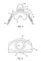
- FIG. 4is a partial top plan view of the nasal mask assembly of FIG. 1 ;
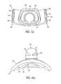
- FIG. 5is a front perspective view of a frame component of the nasal mask assembly of FIG. 1 ;
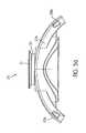
- FIG. 5 ais a top view of the frame of FIG. 5 ;
- FIG. 5 bis a schematic view showing various forces acting on the nasal mask assembly which may affect a patient
- FIG. 5 cis a rear perspective view of the frame of FIG. 5 ;
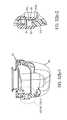
- FIG. 6 ais a top view of an elbow assembly and frame according to another embodiment of the present invention.
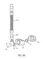
- FIG. 6 bis an exploded view of the embodiment of FIG. 6 a;
- FIG. 7is a partial sectional view of the frame of FIG. 5 ;
- FIG. 8is a side view of a left side yoke of the nasal mask assembly of FIG. 1 ;
- FIG. 8 ais an enlarged view of a right side yoke according to another embodiment of the present invention.
- FIG. 9 ais a top view of a locking clip of the nasal mask assembly of FIG. 1 ;
- FIG. 9 bis a bottom view of the locking clip of FIG. 9 a;
- FIG. 10 ais a side view of a clip and frame in a nearly fully connected condition, according to the present invention.
- FIG. 10 bis a bottom view of the clip of FIG. 10 a;
- FIG. 10 cis a top view of the clip of FIG. 10 a;
- FIG. 10 dis a perspective view of the clip of FIG. 11 a;
- FIGS. 10 e - 10 gillustrate the clip and yoke of the present invention in various connected positions
- FIG. 11is a perspective view of a buckle of the nasal mask assembly of FIG. 1 ;
- FIG. 12is a bottom view of a cross-over strap of the nasal mask assembly of FIG. 1 in a relaxed state
- FIG. 13is a bottom view of the cross-over strap of FIG. 12 in a crossed-over state
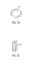
- FIG. 14is a view of a cross-over buckle of the cross-over strap of FIG. 13 ;
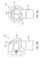
- FIG. 15is a perspective view of a strap loop for use with the nasal mask assembly of FIG. 1 ;
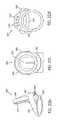
- FIG. 16 ais a perspective view of the swivel elbow shown in FIG. 1 ;
- FIG. 16 bis a side view of a swivel elbow of the nasal mask assembly of FIG. 1 ;
- FIG. 17is a front view of the swivel elbow of FIGS. 16 a and 16 b;
- FIG. 18is a rear view of the swivel elbow of FIGS. 16 a and 16 b;
- FIG. 18 bis a side view of another embodiment of a swivel elbow
- FIG. 18 cis a front view of the swivel elbow of FIG. 18 b;
- FIG. 18 dis a rear view of the swivel elbow of FIG. 18 b;
- FIG. 18 eis a cross-sectional view of the swivel elbow of FIG. 18 b;
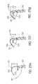
- FIGS. 19 a 1 - 19 c - 2are sequential sectional views of the swivel elbow as shown in FIG. 18 , illustrating connection with a flange extending from the front surface of the frame;
- FIG. 20is a perspective view of a vent cover of the nasal mask assembly of FIG. 1 ;
- FIG. 21is a rear view of the vent cover of FIG. 20 ;
- FIG. 22is a bottom view of the vent cover of FIG. 20 ;
- FIG. 22 bis a perspective view of another embodiment of a vent cover for connection with the swivel elbow of FIG. 18 b;
- FIG. 22 cis a rear view of the vent cover of FIG. 22 b;
- FIG. 22 dis a bottom view of the vent cover of FIG. 22 b;
- FIG. 22 eis a side view of the vent cover of FIG. 22 b;
- FIG. 22 fis a side view of illustrating the vent cover of FIG. 22 b connected to the swivel elbow of FIG. 18 b;
- FIG. 23is a perspective view of a connector tube of the nasal mask of FIG. 6 a;
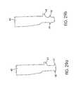
- FIG. 24 ais a face side view of a cushion of the nasal mask assembly of FIG. 1 showing Computer Aided Design (CAD) construction lines;
- CADComputer Aided Design
- FIG. 24 bis a frame side view of the cushion of FIG. 24 a showing CAD construction lines
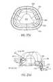
- FIGS. 24 c - 24 fillustrate various perspectives of the cushion shown in FIG. 24 a;
- FIG. 24 gshows a mask cushion in accordance with an embodiment of the invention incorporating a septum notch
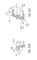
- FIG. 25 ais a perspective view of the cushion shown in FIG. 1 showing CAD construction lines;
- FIG. 25 bis a face side view of the cushion of FIG. 25 a;
- FIG. 25 cis a frame side view of the cushion of FIG. 25 a showing CAD construction lines
- FIG. 25 dis a cross-section taken along line 25 d - 25 d of FIG. 25 b showing CAD construction lines;
- FIG. 25 eis a cross-section taken along line 25 e - 25 e of FIG. 25 b;
- FIG. 25 fis a cross-section taken along line 25 f - 25 f of FIG. 25 b;
- FIG. 25 gis a cross-section taken along line 25 g - 25 g of FIG. 25 b;
- FIG. 25 his a cross-section taken along line 25 h - 25 h of FIG. 25 b;
- FIG. 25 iis an enlarged view of FIG. 25 d showing typical (TYP) dimensions of an embodiment (R-radius);
- FIG. 26is a perspective view of an air tube of the nasal mask assembly of FIG. 1 ;
- FIGS. 27 a - 27 eare partial sectional views of a frame and cushion of the nasal mask assembly of FIG. 1 showing a sequence of positions of assembly and disassembly of the frame and cushion;
- FIG. 28is a partial sectional view of an alternative embodiment of the frame and cushion of the nasal mask assembly of FIG. 1 ;
- FIGS. 29 a - 29 dshow alternative sealing configurations of the cushion of FIGS. 27 a - 27 e.
- FIGS. 30 and 31show various dimensions used to design a mask according to FIG. 1 ;
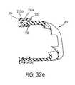
- FIGS. 32 a - 1 - 32 c - 2illustrate an additional embodiment of the present invention for engagement between the frame and cushion, the cushion showing CAD construction lines;
- FIG. 32 dis an enlarged cross-sectional view of the frame shown in FIGS. 32 a - 1 - 32 c - 2 ;
- FIG. 32 eillustrates an additional embodiment of the present invention for engagement between the frame and cushion
- FIG. 33is a perspective view of another embodiment of a frame of the nasal mask assembly.
- FIG. 34is a top view of another embodiment of the yokes of the headgear assembly of the nasal mask assembly
- FIG. 35is an enlarged view of a right side yoke of the headgear assembly shown in FIG. 34 ;
- FIG. 36is a perspective view illustrating the frame of FIG. 33 magnetically coupled to the headgear assembly of FIGS. 34 and 35 ;
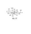
- FIG. 37is a schematic view illustrating the magnetic coupling of the frame of FIG. 33 and the headgear assembly of FIGS. 34 and 35 ;
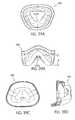
- FIGS. 38A-38Dshow various perspectives of another embodiment of the cushion, the cushion showing CAD construction lines
- FIGS. 39A-39Dshow various perspectives of another embodiment of the cushion, the cushion showing CAD construction lines
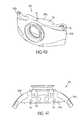
- FIG. 40is a perspective view of another embodiment of a frame of the nasal mask assembly.
- FIG. 41is a bottom view of the frame shown in FIG. 40 ;
- FIG. 42is a top view of an embodiment of the cushion structured to be engaged with the frame shown in FIG. 40 , the cushion showing CAD construction lines;
- FIG. 43is a rear view of the cushion shown in FIG. 42 , the cushion showing CAD construction lines.
- FIG. 1shows one embodiment of an elbow assembly 60 according to the present invention
- FIGS. 6 a - 6 bshow another arrangement of the elbow assembly 60 .
- FIGS. 6 a - 6 bshow another arrangement of the elbow assembly 60 .
- FIGS. 6 a - 6 bshow another arrangement of the elbow assembly 60 .
- FIGS. 6 a - 6 bshow another arrangement of the elbow assembly 60 .
- FIGS. 6 a - 6 bshow another arrangement of the elbow assembly 60 .
- FIGS. 6 a - 6 bshow another arrangement of the elbow assembly 60 .
- Other differences between the embodimentswill be described below.
- several alternative approachesare also described with respect to various parts and/or elements, and those alternative approaches should be considered as additional preferred embodiments of the present invention.
- a nasal mask assembly 10includes a frame 20 and a cushion 40 that is preferably detachably connected to the frame 20 .
- the cushion 40can be permanently attached to the frame 20 using, e.g., co-molding or over-molding techniques, glue and/or mechanical fastening means.
- a swivel elbow assembly 60 and a headgear assembly 80can be attached to the frame 20 .
- FIG. 1shows the nasal mask assembly 10 generally as it is intended to be mounted onto a human head. Of course, the depiction in FIG. 1 is slightly spaced away from the head, or “floating”, for ease of understanding.
- FIG. 1shows the nasal mask assembly 10 generally as it is intended to be mounted onto a human head. Of course, the depiction in FIG. 1 is slightly spaced away from the head, or “floating”, for ease of understanding.
- FIG. 1 bshows the headgear assembly laid flat with the frame 20 removed therefrom.
- FIG. 2illustrates the mask assembly 10 from the left side view
- FIG. 3illustrates a front view thereof
- FIG. 4illustrates a top view thereof.
- FIGS. 2-4the rear portion of the headgear assembly 80 has been removed for clarity.
- frame 20includes an elongated body 22 having a central bore 24 for connecting to the swivel elbow assembly 60 .
- FIG. 5 ais a top view of the frame 20 in which the cushion 40 , the elbow assembly 60 and the headgear assembly 80 have been detached.
- the frame 20includes a main body 20 a , which is designed to accommodate the cushion 40 , and a pair of side frame members 20 b that are preferably formed in one piece with the main body 20 a of the frame 20 .
- FIG. 5 ashows that both side frame members preferably have the same configuration.
- the main body 20 a and the side frame members 20 bhave been designed to have a curvature that generally follows the facial contour of the patient's face on each side of the nose.
- the curvaturefollows a smooth transition from the two side members having an inclusive angle of 120°.
- the main body 20 ais spaced away from the patient's face in the nose region to prevent contacting the patient's nose, while the side frame members 20 b are generally parallel the cheek regions.
- a spaceis maintained between each side frame member 20 b and the cheek of the patient since contact is not desired in this area.
- the side frame members 20 bmay be constructed to include a comfort feature such as pad structure that engages the cheek regions of the patient. Such a pad can have the advantage of assisting in supporting the cheeks when pressure is applied in treatment mode.
- the center of gravity CG 1 ( FIG. 5 b ) of the mask assembly 10can be formed closer to the face of the patient.
- rotative torque or moment created in the vertical plane due, for example, to the weight of the mask assemblycan be reduced.
- the weight of the mask assembly 10can produce torque about an axis A (into the page) that is transverse to the patient's nose in the horizontal plane. That torque can produce forces tending to rotate the mask assembly 10 in the direction of arrow B about the axis A which is generally positioned along the upper lip region of the cushion.
- Such torquemay result in patient discomfort along the upper lip region and/or reduced sealing around the lower bridge region of the nose and/or at the cheek region.
- a center of gravity CG 1 located close to the facecan produce less torque than a mask having a center of gravity CG 2 that is further away from the face.
- torqueforce ⁇ lever arm distance
- torquecan be reduced if the force or the lever arm distance is reduced.
- Similar torquescan be created if the patient is lying on his or her side as well.
- the torqueis affected by the geometry of the elbow, including such features as its length and height in relation to the cushion. It is desirable to minimise the effective lever arm length of the assembly which depends amongst other things on the configuration of the elbow.
- the lever arm of the elbow assemblycan be effectively reduced because the elbow assembly is designed to be connected directly to a gas delivery tube 310 ( FIG. 26 ), without the need for an intermediate swivel connector member 300 ( FIGS. 6 b and 23 ) between the elbow assembly and the gas delivery tube 310 , as is currently used in some prior art.
- a swivelmay be incorporated within the tube. In this way, an additional degree of freedom of movement may be added without increasing the undesirable torque.
- the cushion 40is designed to distribute pressure at least along the lip and cheek regions of the cushion 40 , the possibility or tendency to rotate in the vertical plane is further reduced.
- each of the cheek regions of the cushion 40defines a relatively large contact pressure receiving surface that is elongated in the vertical direction and widened in the horizontal direction.
- the cushion 40at least in the cheek regions, resist rotational movement in the vertical and/or horizontal planes, which helps maintain the cushion 40 in a consistent position on the patient. More details of the cushion 40 are described below in relation to FIGS. 24 a - 25 i .
- the frame 20includes a channel 26 having a generally trapezoidal shape for connecting to the cushion 40 .
- the channel 26includes an inner wall 28 , an outer wall 30 and a channel floor 32 . The channel 26 will be described in further detail below.
- FIG. 6 ashows a frame 20 and elbow assembly 60 that is slightly different than the frame 20 and elbow assembly 60 shown in FIGS. 1-5 c .
- the main differences between the embodimentsreside in the elbow assembly 60 , there are other differences between the frames 20 , cushions 40 , etc., as will be readily seen by comparing the various figures, or understood in conjunction with the description in various sections below.
- Like elementsare indicated with like reference numbers.
- the elbow assembly 60is attached to the mask frame using a C-clip 23 ( FIG. 6 b ) that can be expanded and contracted to fit within a circumferal groove 25 provided on a portion of the elbow assembly 60 that protrudes into the frame 20 using a mechanism similar to that provided on ResMed's ULTRA MIRAGE® mask and as described in U.S. Pat. No. 6,691,707 (Drew et al.).
- An exploded view of the cushion 40 , the frame 20 , the elbow assembly 60 and the gas delivery tubeis shown in FIG. 6 b .
- the C-clip 23has a surface that engages the inside surface of the frame 20 to prevent unwanted disconnection between elbow assembly 60 from the frame 20 .
- the elbow assembly 60may also include one or more vent openings 61 open to atmosphere, for example, for gas washout of exhaled carbon dioxide, among other things.
- the vent openings 61are structured so that treatment pressure will be maintained within the nasal cavity.
- the vent openings 61may be covered with a shell member 65 which is resiliently and removably clipped onto an outer surface of the elbow assembly 60 .
- the vent openings 61 in FIG. 6 aare visible through the clear shell member 65 . Details of the shell member 65 and the C-clip are described in the ResMed's U.S. Pat. Nos. 6,532,961, 6,691,707 or PCT Application No. PCT/AU00/00097 (WO 00/78384), all of which are incorporated herein by reference.
- the inner wall 28 of channel 26preferably extends away from the frame 20 to a distance that is greater than the distance that the outer wall 30 extends away from the frame 20 .
- FIGS. 5 c and 32 dalso show that the inner wall 28 extends away from the frame 20 a distance that is greater than the distance over which the outer wall 30 extends away from the frame 20 .
- the thickness of the inner wall 28is in the range of about 1-2 mm, preferably 1.4 mm
- the thickness of the outer wall 30is in the range of about 1-2 mm, preferably 1.4 mm
- the distance between the tops of the inner and outer walls 28 , 30is in the range of 0.5-10 mm, preferably 2 mm.
- the width of channel 26 between the upstanding surfaces of the inner and outer walls 28 , 30 that face each otheris in the range of about 2-10 mm, preferably 5 mm.
- the inner wall 28provides a visual and/or tactile cue to cushion alignment and then will facilitate the continuance of the engagement process by guiding the edge of the side wall or central portion 215 ( FIGS. 24 e and 27 a ) of the cushion 40 into channel 26 , as will be more fully explained with reference to FIGS. 27 a - 29 d and 32 a - 1 - 32 c - 2 .
- the shape of the channel 26e.g., a generally trapezoid shape as seen in FIG.
- 5 cis selected so as to achieve guidance to correct cushion orientation relative to the channel 26 without the need for additional guide pieces as would be the case should the channel 26 have a more symmetrical shape such as an equilateral triangle, circle, square or rectangle. Nevertheless, the cushion channel 26 could adopt any of these shapes.
- the frame 20includes a locking clip receiver assembly 34 positioned on each side of the frame 20 for connecting to a respective locking clip 82 ( FIGS. 9 a and 10 a ) of the headgear assembly 80 .
- Each locking clip receiver assembly 34includes an engagement face 35 ( FIG. 5 c ), a central support slot 36 and two locking slots 38 positioned on opposite sides of the central support slot 36 .
- the central support slots 36 and locking slots 38have a generally rectangular cross-section.
- Each of the locking slots 38includes a locking flange 39 ( FIG. 7 ) positioned on an outer wall thereof for engagement with a respective locking tab 116 ( FIGS. 9 a and 9 b ) of one of the locking clips 82 , as described below.
- the channel 38may be provided with a slot 71 ( FIG. 10 a ) in the outer wall of the frame 20 in addition to or in replacement of the locking flange 39 ( FIG. 7 ).
- the slots 71 on the bottom of the frame 20can be seen in FIG. 5 a , while FIG. 4 shows the slots 71 from the top of the frame 20 .
- the slots 71need not extend through the side walls of the frame 20 .
- FIG. 1 bshows headgear assembly 80 in accordance with an embodiment of the invention, without the frame 20 or cushion 40 .
- the headgear assemblyis shown laid flat.
- headgear assembly 80includes a pair of front straps 84 , with the left and right front straps 84 preferably being mirror images of each other.
- Each front strap 84is in the general form of a “Y” and has a front strap end 86 , a top strap end 88 and a rear strap end 90 all formed in one piece or otherwise interconnected together by mechanical fastening or the like.
- the strapsare made from laminated fabric and foam.
- One commercially available materialis “Breath-O-Prene”TM manufactured by Accumed Inc., USA.
- a yoke 92is attached to each front strap 84 .
- Each yoke 92has the same general shape as the corresponding front strap 84 and has a front end 94 , a top end 96 and a rear end 98 .
- Each yoke 92is constructed of a somewhat rigid material, e.g., plastic, and has a thickness in the range of 0.3-2.0 mm, preferably 1 mm.
- the plasticexamples include nylon 11 or polypropylene.
- the yoke 92is attached to the corresponding front strap 84 with adhesives, stitching, or other known attachment mechanisms.
- the strap and yoke arrangementcan have different flexibilities in different directions, for example being stiff in a first direction (e.g., to resist the deformation due to the weight of the swivel elbow, associated conduits, etc.), but flexible in a direction generally orthogonal to the first direction.
- the relative stiffness of the yokeshelps position the frame and cushion in the correct position on the user.
- the top ends 96 and rear ends 98 in this embodimentdo not extend as far as the top strap ends 88 and rear strap ends 90 of the front straps 84 .
- the top end 96may be extended along the entire length of the top strap 88 and be formed integrally or in one piece with a connector element 128 ( FIG. 1 ).
- the yokes 92are also narrower than the front straps so that when they are attached together, the softer material of the front straps 84 extends beyond the more rigid material of the yokes 92 , thereby preventing or at least reducing the opportunity for contact between the user and the more rigid material of the yokes 92 that could cause irritation or discomfort.
- the straps and associated yokesare formed from a multilayer construction, e.g., two layers, the strap 84 and yoke 92 could be formed of a single material, so long as patient comfort and the appropriate rigidity/flexibility are maintained.
- the yokes 92add to the rigidity of the straps 84 in certain planes and directions, which assists in stabilizing the mask assembly 10 on the head of the patient during use. In other planes and directions, the yoke and strap assembly has a different rigidity. For example, the strap and yoke should be able to resist bending or curling towards or away from the patient's face. In general, the strap 84 and yoke 92 should be able to maintain their positions with respect to the head of the patient when the straps 84 and yokes 92 are connected to the frame 20 .
- the mask frame 20need not be provided with a forehead support assembly, which may further increase the comfort of the patient since the patient's field of view is less obstructed as compared to masks with forehead supports.
- forehead supports of the type described abovemay be provided if desired for additional stability or comfort.
- the mask frame 20need not be provided with a chin strap, although a chin strap may be provided if desired for additional stability or comfort.
- the shapes of the straps 84 and yokes 92are selected to avoid interference with the patient's field of view.
- each yoke 92are connected to the frame 20 below the patient's eyes, and preferably extend along a curved arc resting across the cheek regions.
- the top end 88 of each strap 84 and the top end 96 of each yokeextend away from the intersection of the Y along the temple region of the patient's head.
- the rear end 98 of the yoke 92 and the rear end 90 of the strap 84are curved downwardly and around the ear of the patient for connection with the rear strap member 138 , as more fully described below. Due to the rigidity provided by the yokes 92 , the straps 84 are better able to maintain a predetermined shape.
- a certain degree of flexibility of the yoke 92 and strap 84is provided such that variations in patient physiology can be accommodated to a certain degree.
- the thickness of the yokecan also vary across its profile to modify flexibility characteristics, for example, thicker regions may be stiffer.
- each yoke 92has a mounting flange 100 positioned on the front end 94 .
- the mounting flange 100has an aperture or keyhole 101 leading to a bore 103 , see FIG. 8 a .
- Two semi-annular flanges 102are separated from each other by slots 104 .
- a radial inner surface of the semi-annular flanges 102forms the central bore 103 .
- the yoke 92also has a spring tab 106 positioned rearward of the mounting flange 100 with a front portion of the spring tab connected to the yoke 92 and a rear portion separated from the yoke 92 by space 107 to be able to flex with respect to the yoke 92 when pressure is applied to the spring tab 106 .
- the spring tab 106preferably has a plurality of raised teeth 108 positioned in an arc about an axis of the mounting flange 100 .
- the spring tab 106also has a textured surface 110 ( FIG. 8 ) or a raised positioning member 110 a ( FIG. 8 a ) at its free end to assist the user in locating, engaging and manipulating the spring tab 106 .
- FIG. 8textured surface 110
- FIG. 8 a raised positioning member 110 aFIG. 8 a
- FIG. 8 ais an enlarged view of a right side yoke 92 and strap 84 , like that shown in FIG. 8 , to better show details of yoke 92 , including the manner in which the yoke 92 is stitched to the head strap 84 .
- Other fixing mechanismssuch as locking or friction may be used.
- each locking clip 82is adjustably attached to each mounting flange 100 .
- each locking clip 82includes a main body 112 .
- Two spring arms 114are attached to opposite sides of the main body 112 and extend away from the main body in a generally parallel manner.
- a latch hook 116is attached to a free end of each spring arm 114 .
- the clip 82can be inserted into releasable engagement with the locking clip engagement receiver 34 of the frame 20 .
- FIG. 10 aonly one clip 82 is shown and the clip 82 is not assembled to the yoke 92 .
- Each latch hook 116is received within a respective channel 38 ( FIG. 5 c ) of the frame.
- FIG. 10 athe distal ends of the latch hooks 116 are shown in a position just before they outwardly flex into the respective recesses 71 of the channel 38 .
- FIG. 4shows the distal ends of the latch hooks in the engaged position within the recesses 71 .
- the clip 82 or at least the latch hook 116 thereofcould be formed in the frame 20
- the channel 38 or at least the recess 71could be formed on the strap and/or yoke.
- FIGS. 4 and 10 aalso show that the outward surfaces of the locking clip 82 and the frame 20 preferably form a generally continuous surface, which is not interrupted when connected.
- the locking clip 82is as wide as the frame 20 at each end, which facilitates tactile location of the locking clip by the patient.
- the spring arms 114are designed to flex within the plane of the locking clip main body, which further improves the ease by which the locking clips 82 are attached and detached. This positioning improves the ergonomics of the release mechanism.
- the patient's thumb and an opposing fingercan be used to readily locate and operate the locking clips 82 . Also, because of their increased size, patients with minimal dexterity can operate the locking clips 82 .
- the locking clips 82are connected to the strap 84 /yoke 92 so that length adjustment between the locking clips 82 and the strap 84 /yoke 92 is not necessary.
- the locking clip 82includes a retaining flange 118 ( FIG. 9 b ) extending transversely outward from the main body 112 .
- the retaining flange 118has a central hub 119 extending along an axis of the retaining flange 118 and two retaining tabs 120 extending transversely from the central hub 119 on opposite sides of the central hub 119 .
- FIGS. 10 b - dshow more details of the locking clips 82 shown in FIG. 10 a , which are similar to features shown in FIGS. 9 a and 9 b .
- the locking clip 82has been shown to be separate from the yoke 92 , it is understood that the clip and yoke 92 could be formed in one piece if relative movement and/or detachment between the two is not required. Conversely, the clip 82 and frame 20 can be formed as an integral unit, and the clip portion could be connected to the yoke.
- the retaining flange 118is sized and shaped such that the retaining tabs 120 can be aligned with the slots 104 and the retaining flange 118 axially inserted into the mounting flange 100 of the yoke 92 .
- the central hub 119is sized to have a close tolerance with the central bore 103 so that the locking clip 82 and yoke 92 are rotationally supported with one another.
- FIG. 10 e - gshow the locking clip 82 in various positions with respect to the yoke 92 .
- the tabs 120 of the clip 82have been inserted through the openings 104 of the yoke 92 , and the clip 82 has been rotated slightly along the direction of arrow A such that the upper surfaces of the tabs 120 snugly engage the inside surfaces of the semi-annular portions 102 .
- the clip 82can be removed from the yoke 92 .
- FIGS. 10 f and 10 gshow the clip 82 in different rotational orientations with respect to the yoke 92 .
- the locking clipalso has a plurality of raised teeth 122 positioned in an arc about an axis of the retaining flange 118 .
- the teeth 122are constructed and arranged so as to engage the teeth 108 on spring tab 106 .
- the teeth 108 and 122can be configured so that when a predetermined torque is applied to the locking clip 82 , the teeth 122 will automatically force the teeth 108 and spring tab 106 downwardly to allow rotation of the locking lip 82 until the torque is removed and the teeth 108 re-engage the teeth 122 .
- the locking clip 82can thus be rotationally adjusted with respect to the yoke 92 within an angle of approximately 50-100°, and preferably 75°, depending on the position of engagement between teeth 108 and teeth 122 .
- the angle of available rotational adjustmentcan be altered as desired by altering the number and positioning of teeth 108 and 122 .
- the adjustment angle rangereflects the relative cushion positions required on the face.
- Rotational adjustment with a toothed system as described aboveallows easy adjustment by the patient and allows a broad range of positions to accommodate a wide range of patients' faces.
- the patientmay adjust both locking clips 82 to have the same angle with respect to the yokes 92 .
- the patientmay adjust the locking clips 82 such that the locking clips 82 have different respective angles with respect to the yokes 92 .
- the toothed systemallows the patient to easily set and reproduce the desired angle for each locking clip 82 .
- the toothed systemmay allow relative movement between each locking clip and its respective yoke in, for example, five positions, which should accommodate most faces. Of course more or less than five positions could be used instead, depending on application.
- the mask systemmay include a nonadjustable clip arrangement which fixes the rotational position of the locking clips 82 with respect to the yokes 92 .
- the teethare large enough for the patient to easily determine the relative positions of the locking clip with respect to the yokes.
- the spring tab 106is configured and positioned such that the patient cannot inadvertently depress the spring tab 106 , e.g., by rolling over on the locking clip/yoke during sleeping, to cause the locking clip 82 to move relative to the yoke 92 .
- the locking clip 82extends further outwardly from the yoke 92 than the spring tab 106 . That is, the spring tab 106 is positioned lower than the outer edge of the locking clip 82 .
- the positioning of the locking clip 82 with respect to the spring tab 106prevents inadvertent actuation of the spring tab 106 .
- the spring tab 106is connected to the yoke 92 such that the yoke 92 can flex toward and away from the spring tab 106 without disengaging the teeth 108 of the spring tab 106 from the teeth 122 of the locking clip 82 .
- the central hub 119might be located on the yoke 92 while its reciprocal yoke central bore 103 may be located on the locking clip 82 .
- each sub-assembly and its reciprocalmay be reversed.
- the yoke 92 and locking clip 82may be adjustably connected by way of a screw or clamping mechanism, e.g., a part that may be separate from the yoke and clip, which can be used to selectively connect the yoke 92 and clip 82 in a plurality of desired positions.
- the central bore 103can be shaped in any manner that allows detachment and attachment between the yoke and the clip. Also, a system of replacement yokes that would allow a fixed angle with respect to the locking clip may be used.
- the locking clip 82also includes a central support tab 124 extending outward from the main body 112 between and generally parallel to spring arms 114 .
- the central support tab 124is configured to have a close fit with the central support slot 36 , so that when the central support tab 124 is inserted into the central support slot 36 , little rotational, rocking or side to side movement is permitted between the locking clip 82 and the locking clip receiver assembly 34 .
- Central support tab 124is longer than arms 114 to assist with alignment into the frame.
- the locking clip 82also has an engagement face 125 that engages engagement face 35 ( FIG. 5 c ) when the locking clip 82 is inserted into the locking clip receiver assembly 34 to provide additional support for the locking clip 82 .
- the latch hooks 116 and/or the central support tab 124may have tapered widths and/or thicknesses to facilitate entry into slots 36 , 38 . Also, the latch hooks 116 and/or central support tab 124 may have rounded or contoured edges to facilitate entry into slots 36 , 38 . Further, the central support tab 124 may have a groove that engages a protrusion provided in the central support slot 36 to facilitate entry of the central support tab 124 into the central support slot 36 . Alternatively, the central support tab 124 may have a protrusion that engages a groove provided in the central support slot 36 .
- the spring arms 114are forced toward one another as the latch hooks 116 are inserted into recesses 71 ( FIG. 4 ) or ride up and over the locking flanges 39 ( FIG. 7 ). Once the latch hooks 116 have cleared the locking flanges 39 or recesses 71 , the spring arms 114 can spring outward, providing a locking engagement between the latch hooks 116 and the locking flanges 39 and/or recesses 71 . Sufficient clearance is provided in locking slots 38 to allow the necessary movement of the latch hooks 116 to clear the locking flanges 39 .
- the respective left and right front strap assembliesincluding front straps 84 , yokes 92 and locking clips 82 , can be attached to the frame 20 and the yokes 92 and front straps 84 rotationally adjusted with respect to the frame 20 within an angle of approximately 50-100°, and preferably 75°.
- the locking clip 82is a unitary plastic piece formed by injection molding.
- the plasticinclude nylon, acetal, polycarbonate, and polypropylene.
- the retaining tabs 120are formed during the molding process by mold projections that leave bores 126 extending through the main body 112 of the locking clip 82 , thereby separating under surfaces of the retaining tabs 120 from the main body 112 .
- FIGS. 33-37illustrate an alternative embodiment for removably coupling the frame 420 and the headgear assembly 480 .
- the frame 420 and the yokes 492are structured such that the yokes 492 may be magnetically coupled to the frame 420 .
- the frameincludes a main body 420 a and a pair of side frame members 420 b . Similar to the embodiment of frame 20 , the main body 420 a is structured to be removably coupled with the cushion 40 .
- Each side frame member 420 bincludes a first connector portion 434 for connecting to a second connector portion 435 provided by the yoke 492 of the headgear assembly 480 .
- the first connector portion 434includes a retaining structure 418 that extends outwardly from the side frame member 420 b .
- the retaining structure 418is structured to retain a magnet 419 .
- the magnet 419is constructed of Neodymium and has a cylindrical shape with a diameter of 6.35 mm and a thickness of 6.35 mm.
- the retaining structure 418may be structured to retain a magnet of any suitable size and shape.
- the outer edges of the side frame members 420 beach include a plurality of raised teeth 422 positioned in an arc.
- the yokes 492 of the headgear assembly 480each include structure that is similar to the yokes 92 of headgear assembly 80 .
- the yokes 492each include the second connector portion 435 having a mounting flange 400 positioned on the front end 494 thereof.
- the mounting flange 400has an aperture or keyhole 401 leading to a bore 403 .
- Two semi-annular flanges 402are separated from each other by slots 404 .
- a radial inner surface of the semi-annular flanges 402forms the central bore 403 .
- the yoke 492also has a spring tab 406 positioned rearward of the mounting flange 400 with a front portion of the spring tab 406 connected to the yoke 492 and a rear portion separated from the yoke 492 by space 407 to be able to flex with respect to the yoke 492 when pressure is applied to the spring tab 406 .
- the spring tab 406preferably has a plurality of raised teeth 408 positioned in an arc about an axis of the mounting flange 400 .
- the spring tab 406also has a raised positioning member 410 at its free end to assist the user in locating, engaging and manipulating the spring tab 406 .
- the yoke 492includes a ferrous metal disk 412 that is secured within the bore 403 .
- the metal disk 412is a steel washer with a diameter of 14 mm and a thickness of 1 mm.
- the metal disk 412may have any suitable size and shape that can be mounted within the bore 403 of yoke 492 .
- a magnet of suitable size and shapemay be used in place of the metal disk 412 .
- the first connector portion 434 of the frame 420is engaged with the second connector portion 435 of the yoke 492 such that the magnet 419 is magnetically coupled with the metal disk 412 .
- the magnet 419is axially inserted into the bore 403 so that the magnet 419 is positioned adjacent to or engaged with the metal disk 412 which allows the magnetic attraction between the magnet 419 and the metal disk 412 to axially retain the yoke 492 to the frame 420 .
- the strength of the magnetic attraction between the yokes 492 and the frame 420may be increased by replacing the metal disk 412 with a magnet, as discussed above.
- the retaining structure 418is sized to have a close tolerance with the bore 403 so that the frame 420 and yoke 492 are rotationally supported with one another.
- the teeth 422 on the frame 420are constructed and arranged to engage the teeth 408 on the spring tab 406 when the frame 420 is magnetically coupled with the yoke 492 .
- the yoke 492can be rotated to a desired position with respect to the frame 420 .
- the spring tab 406can then be released so that teeth 408 engage teeth 422 in the desired position (within a pitch of the teeth) and rotationally lock the frame 420 with respect to the yoke 492 .
- the teeth 408 and 422can be configured so that when a predetermined torque is applied to the yoke 492 , the teeth 422 will automatically force the teeth 408 and spring tab 406 downwardly to allow rotation of the yoke 492 until the torque is removed and the teeth 408 re-engage the teeth 422 .
- the yoke 492can thus be rotationally adjusted with respect to the frame 420 within an angle of approximately 50-100°, and preferably 75°, depending on the position of engagement between teeth 408 and teeth 422 .
- each side frame member 420 bmay be oriented such that an incorrect attachment (e.g., left side yoke 492 to right side frame member 420 b ) is indicated by magnetic repulsion.
- an incorrect attachmente.g., left side yoke 492 to right side frame member 420 b
- the magnet 419 on one side frame member 420 bis oriented so that it will only magnetically couple with one of the yokes 492
- the magnet 419 on the other side frame member 420 bis oriented so that it will only magnetically couple with the other of the yokes 492 .
- sensory indication of correct attachment of the frame 420 to the headgear assembly 480is achieved by magnetic attraction of correctly paired yokes 492 and side frame members 420 b .
- This constructionensures that the headgear assembly 480 and frame 420 are assembled correctly. Further, this construction enables the frame 420 to be easily coupled with the headgear assembly 480 , even in the dark, as the magnet 419 will automatically locate itself in the correct position with respect to the metal disk 412 .
- the headgear assembly 480may be easily detached from the frame 420 by applying a suitable disengagement force that is greater than the attractive magnetic force between the magnet 419 and the metal disk 412 .
- first connector portion 434 on the frame 420may provide a ferrous metal member and the second connector portion 435 on the yoke 492 may provide a magnet.
- Each front strap 84includes a ladder-type buckle 128 attached to the top strap 88 to connect the top strap 88 with a top strap 140 of cross-over strap 138 . See FIGS. 1-3 and 11 .
- the buckle 128can be attached to the top strap 88 with adhesives, stitching and/or other known manners, such as being manufactured integral with the strap.
- the buckle 128includes a plurality of bores 130 evenly spaced around an attachment tab 132 in the form of a square to allow the buckle to be stitched to the top strap 88 .
- the bucklefurther includes a crossbar 134 and a crossbar 136 , around which the top strap 140 can be threaded, in a known manner, so that top strap 140 wraps around crossbar 136 and a free end of top strap 140 is positioned between crossbar 134 and a remainder of top strap 140 .
- a single cross bar bucklecan also be used if used in combination with a strap loop to hold the strap in position.
- other connector memberscan be used instead of the buckle, as is known in the art.
- cross-over strap 138has a generally elongated shape in a relaxed state with two top straps 140 extending upward from a cross-strap 142 having ends 144 .
- the two top straps 140are threaded through a cross-over buckle 146 , so that they are held in the cross-over position. See FIGS. 13 and 14 .
- the left top strap 140 of cross-over strap 138crosses over to connect with the buckle 128 of right top strap 88 and the right top strap 140 of cross-over strap 138 crosses over to connect with the buckle 128 of left top strap 88 .
- a strap loop 148can be used to hold down free ends of the respective straps. See FIG. 15 .
- the strapsare supplied oversized and then cut to length to suit the person.
- buckles 150( FIG. 1 ) can be attached to cross-strap ends 144 so that the cross-strap ends 144 can be connected to the respective rear strap ends 90 of front straps 84 .
- the swivel elbow assembly 60 of FIG. 6 amay be the same as is currently used in ResMed Limited's ULTRA MIRAGE® mask, which employs an internal C-clip member, as described above.
- the elbow assembly 60 of FIG. 6 ais intended to be used with a connector tube 300 ( FIG. 23 ).
- the connector tube 300is provided between the elbow assembly 60 and the gas delivery tube 310 ( FIG. 26 ).
- the swivel elbow assemblymay be constructed in accordance with FIGS. 1-4 and 16 - 22 .
- Such a swivel elbow assembly 60may include a swivel elbow 160 and a vent cover 180 .
- Swivel elbow 160is rotationally connected to frame 20 .
- a further swivelis connected to the end of tube 310 , as shown in FIG. 6 b.
- swivel elbow 160includes an intake port 162 and an exhaust port 164 .
- the air tube 310( FIG. 26 ) is preferably directly connected to a stem 166 of swivel elbow 160 (without connector tube 300 ) to supply pressurized breathable air or gas from a pressurized supply through air tube 310 , intake port 162 and into cushion 40 for breathing by the patient.
- the exhaust port 164is separated from the intake port 162 using, for example, a baffle 161 provided within the interior portion of the elbow 160 . See FIGS. 18 and 19 a - 1 .
- the baffle 161has a generally planar configuration.
- the baffle 161may have a curved configuration or any other suitable configuration for separating the exhaust port 164 from the intake port 162 .
- the orientation of the intake and exhaust ports 162 , 164was selected such that the incoming gas, indicated by the directional arrow in the intake port 162 , less directly impacts the flow of gas washout along the exhaust port 164 .
- the gas entering the elbow 160is less likely to flow directly into the exhaust port 164 since the baffle 161 forces the incoming air to take a tortuous path, e.g., turn around about 180 degrees, before being able to exit through the exhaust port 164 .
- the elbow 160includes an end portion 169 that is adapted to engage the aperture 24 provided in the frame 20 , to provide gas into the nasal cavity formed by the frame 20 and the cushion 40 .
- the baffle 161terminates just inside the end portion 169 of the elbow.
- a flexible quick release mechanismincludes a collar 173 and an apron 170 .
- the collar 173includes a generally T-shaped member, as seen in FIG. 16 b , that surrounds the end portion 169 of the elbow 160 .
- the end portion 169 of the elbow 160extends beyond the collar 173 to improve alignment when assembling into frame 20 .
- the collar 173is spaced away from the end portion 169 in concentric relation so as to form a receiving space 183 between the collar 173 and the end portion 169 , as shown in FIG. 18 .
- the apron 170is preferably formed as an integral part of the elbow 160 , and is connected to the lower leg of the T-shaped collar 173 .
- Two grooves 167are provided between the collar 173 and the apron 170 .
- a portion 167 a of the groove 167allows the lower leg of the T-shaped collar 173 to flex with respect to the apron 170 .
- a portion 167 b of the grooveallows the cross portion of the T-shaped collar 173 to flex outwardly and inwardly with respect to the end portion 169 of the elbow 160 .
- FIGS. 19 a - 1 - 19 c - 2show sequential views illustrating connection between the elbow 160 and the frame 20 .
- FIGS. 19 a - 1 - 19 a - 2show a cross section of the elbow 160 just before connection with the mask frame 20 .
- FIGS. 19 b - 1 - 19 b - 2show the elbow 160 and frame 20 in the nearly connected condition
- FIGS. 19 c - 1 - 19 c - 2show the elbow and frame in the fully connected condition.
- the frame 20includes a flange 21 provided at a distal end of a wall 25 defining the aperture 24 .
- FIGS. 5 and 5 ashow the flange 21
- the embodiment of FIG. 6 adoes not show or include such a flange since a different elbow assembly 160 is employed.
- As the flange 21 is inserted within the space 183it engages protrusions 181 formed in the inside surface of the collar 173 . In this embodiment, only two protrusions 181 are provided.
- the protrusions 181are ramped or inclined such that engagement with the flange 21 causes outward flexure ( FIGS.
- a preferred form of the elbow 160includes textured protrusions 185 to assist users to locate the release points.
- the distance between the opposed textured portions 185i.e., the diameter of the collar 173 , is approximately 35-45 mm, and preferably 40 mm.
- the elbow 160also is adapted to connect directly to the gas delivery tube 310 ( FIG. 26 ) without the connector 300 shown in FIG. 23 . (See FIG. 1 ).
- FIG. 6 bshows the connector 300 between the elbow and the gas delivery tube 310 .
- Removal of the connector 300is advantageous because the length of the effective lever arm of the combined elbow and connector 300 ( FIG. 6 b ) may increase the possibility that unwanted levels of torque are applied to the frame 20 or mask assembly 10 relative to the patient's head/face.
- the effective length of the level armcan be reduced, which results in less torque being applied to the mask assembly which results in increased stability. With increased stability, patient comfort is increased and compliance is increased.
- the inside surface of the wall 25 of the frame 20sealingly engages the outside surface of the end portion 169 of the conduit as shown in FIG. 19 a - 1 - 19 c - 2 .
- These surfacesengage one another for a distance of approximately 1-10 mm, preferably 6 mm, which helps to seal as well as to provide stability to the connection between the elbow 160 and the frame 20 .
- a portion of the wall 25extends inside the mask to further increase the area of contact between the elbow 160 and the frame 20 .
- an end portion 173 a of the collar 173is flush with the outside surface 20 c of the frame 20 , as shown in FIGS.
- the wall 25includes a flange 25 a ( FIG. 19 c - 2 ) to form a stop for the insertion of the end portions 169 , and to permit a controlled leak between the elbow 160 and frame 20 .
- the leak between the elbow 160 and frame 20is minimal.
- a sealis provided between the elbow 160 and frame 20 to prevent a leak.
- the elbow 160is configured to allow the patient to attach and detach the elbow 160 from the frame 20 with one hand. This is advantageous when cleaning the mask or if the patient should choose to interrupt treatment during a session, while intending to resume treatment a short time later.
- the elbow assembly 60 and frame 20 connectionallows the patient to rapidly disconnect the elbow 160 from the blower's gas delivery tube while keeping the mask frame, cushion and headgear in place on the patient's head during a momentary treatment interruption.
- the aperture 24is large enough to lower impedance, to thereby enable the patient to breathe comfortably since a sufficient amount of gas can be accommodated by the aperture 24 .
- the aperture 24has an area of at least 180 mm 2 .
- the aperture 24has a diameter in the range of 20-30 mm, preferably 27 mm, and an area in the range of 200-600 mm 2 , preferably in the range of 500-600 mm 2 .
- the aperturehas a generally circular shape.
- the aperturemay have a non-circular shape.
- the framemay have a plurality of apertures therethrough with the elbow coupled to the frame such that it surrounds the plurality of apertures.
- a mask in accordance with an embodiment of the inventiondiffers from prior art mask arrangements which included quick release mechanisms with narrower apertures. Such narrower apertured quick release mechanisms could lead to patient discomfort, for example anxiety or claustrophobia. Discomfort is exacerbated by increased CO 2 re-breathing or increased flow impedance.
- Vent cover 180includes a main body 182 having a lower bore 184 , curved portion 186 and top portion 188 . See FIGS. 20-22 .
- the main body 182also includes at least one vent 190 , and in a preferred embodiment, a plurality of vents 190 extending from an interior of the vent cover to an exterior of the vent cover.
- Top portion 188 of vent cover 180includes flange or aperture 192 for engaging latch 168 of swivel joint 160 .
- the vent cover 180includes an aperture 192 .
- the vent cover 180is connected to the swivel joint 160 by placing the stem 166 of the swivel joint 160 through lower bore 184 of the vent cover 180 .
- vent cover 180is then moved toward the swivel joint 160 until the latch 168 extends through the aperture 192 , as shown in FIG. 1 .
- This configurationallows for the vent cover 180 to remain in the vicinity of the elbow assembly 160 and/or mask assembly 10 , as it is captured by the elbow 160 or the gas delivery conduit. This is convenient in that should the vent cover 180 become dislodged during cleaning or by inadvertence, it will not drop and become lost, as it is retained by the mask assembly.
- FIG. 19 c - 1includes an arrow B that approximates the path exhaust gas follows when the vent cover is in position. This arrangement has an additional advantage in that the vent direction reduces or prevents irritation of a bed partner of the patient by gas flow from the mask.
- FIGS. 1-4show the elbow 160 and vent cover 180 in the connected position.
- a spacer 163is provided to ensure that the vent cover 180 is spaced sufficiently away from the exterior surface of the elbow 160 , which especially helps prevent the air gap from collapsing since the vent cover is preferably made of a resilient flexible material.
- the vent covercould be made of a plastic member somewhat like the cover used in the Ultra MirageTM, if desired.
- this vent arrangementcan be replaced or supplemented using ResMed's vent assembly disclosed, for example, in U.S. Pat. No. 6,561,190, incorporated herein by reference in its entirety.
- FIGS. 18 b - 18 eillustrate another embodiment of the swivel elbow, indicated as 360 , that is adapted to be connected to the vent cover 380 illustrated in FIGS. 22 b - 22 e .
- the swivel elbow 360includes a flange 361 provided at a distal end of a wall 362 surrounding the outlet of the exhaust port 364 .
- FIGS. 18 d and 18 eshow the intake port 365 , the exhaust port 364 , and a baffle 369 that separates the intake and outlet ports 365 , 364 .
- the baffle 369has a curved configuration.
- the baffle 369curves generally downwardly as it extends from the inlet of the exhaust port 364 to the outlet of the exhaust port 369 .
- the baffle 369may have a generally planar configuration similar to baffle 161 shown in FIG. 19 a - 1 .
- the bafflemay have any other suitable configuration to separate the intake and outlet ports 365 , 364 .
- the vent cover 380includes a main body 382 having a lower bore 384 , an intermediate portion 386 and top portion 388 .
- the main body 382also includes a plurality of vent holes 390 extending from an interior of the vent cover to an exterior of the vent cover.
- the top portion 388 of the vent cover 380includes a collar 392 for engaging the flange 361 of swivel elbow 360 .
- the vent cover 380is connected to the swivel elbow 360 by placing the stem 366 of the swivel elbow 360 through lower bore 384 of the vent cover 380 .
- the vent cover 380is then moved toward the swivel elbow 360 until the collar 392 latches onto the flange 361 of the swivel elbow 360 .
- the collar 392is stretched to overcome the flange 361 , and firmly grips the flange 361 due to its resiliency and elasticity.
- the collar 392has a generally circular shape so that stress (“hoop stress”) applied to the flange 361 and wall 362 is evenly distributed. Similar to the embodiment of vent cover 180 , this configuration allows for the vent cover 380 to remain connected on in the vicinity of the swivel elbow 360 and/or mask assembly, as it is captured by the elbow 360 or the gas delivery conduit.
- the vent covercan be considered “self-holding” in that it can be held in place on the elbow to cover the exhaust passage without an additional securing mechanism.
- the vent coveris held onto the elbow via the ring-shaped lower bore 184 as the patient stretches the collar 392 over the flange 361 , which minimizes the chances for losing the vent cover if the first assembly attempt is not successful.
- FIG. 22 fshows the swivel elbow 360 and vent cover 380 in the connected position.
- the swivel elbow 360includes a wall 363 that ensures that the vent cover 380 is spaced sufficiently away from the exterior surface of the swivel elbow 360 , which especially helps prevent the air gap from collapsing since the vent cover 380 is preferably made of a resilient flexible material.
- the vent cover 380includes a recess 389 ( FIG. 22 c ) on an inner surface of the top portion 388 that engages the wall 363 .
- the cushionis designed to rest on the face and apply pressure around its perimeter while minimizing and/or avoiding contact with pressure sensitive regions on the face. Some parts of the face require special attention to achieve a balance of pressure and seal. It is also desirable to provide a low profile mask to improve patient comfort level by improving stability, and to reduce the forces which may tend to pivot the mask relative to the patient's face. Properties are listed below with the measures taken to create a successful design.
- the cushionhas a face-contacting side and a non face-contacting side with a wall therebetween.
- the non-face contacting side of the cushionengages with the mask frame.
- the shape of the cushion on its face-contacting sideis generally trapezoidal.
- the shape of the cushion on the facecontrasts with prior art cushions having a generally triangular shape.
- An advantage of this trapezoidal shapeis that it assists sealing at a point lower down the nose without impeding flow through the patient's or user's nasal vents (that is, in the region of the lateral nasal cartilage and just below the nasal bone on either side of the nose).
- the cushionis positioned on a lower portion of the nasal bridge region of the patient.
- the cushionis configured and positioned such that contact pressure of the cushion on the nasal vents is minimized or eliminated.
- the shape of the cushionmay be altered, e.g., a triangular or other non-trapezoidal shape could be used, keeping in mind that localized pressure points on the lower nasal bridge region and occlusion of the nasal vents should be avoided.
- Some prior art mask cushionspush on the nasal vents which can increase the impedance of the nasal vents to airflow.
- both the face-contacting and non face-contacting sides of the cushionhave the same general trapezoidal shape.
- a combination of support structure and sealing structureis provided in the region of the face contacting side of the cushion.
- the support and sealing structuresmay be provided as part of the cushion, or alternatively using separate components. Where the support and sealing structures are provided as part of the cushion, the cushion may have a single-walled, double-walled or triple- or more walled construction.
- the sealing structureis provided by a thin membrane, whereas the support structure is provided by a thicker frame.
- the center and sides of the nasal bridgeare particularly sensitive to contact pressure.
- the supporting elemente.g., frame 200 shown in FIG. 24 a
- the supporting elementcan be designed to totally avoid contact with the adjacent portion of the overlying face-contacting element (e.g., membrane 205 shown in FIG. 24 a ), thereby allowing the membrane 205 alone to seal. While localized points of contact pressure should be avoided in the nasal bridge region, especially at the sensitive apex thereof that contacts the lower nasal bridge region, the seal must be maintained.
- the lower nasal bridge regionis positioned generally where the bony region of the nasal bridge transitions to a portion of the nose containing more cartilage.
- the forces that are applied to the faceshould be substantially evenly distributed around the entire perimeter of the cushion 40 .
- An aspect of the inventionis that the facial contact pressure is controllably distributed around the face.
- the forces applied to the lower nasal bridge regioncan be spread out along a relatively wider section of the membrane 205 , to avoid the localized forces, while the forces in the lip and cheek regions can be slightly more localized, e.g., spread out over less distance in the width direction, since forces can be more comfortably accommodated in the lip and, particularly, in the cheek regions.
- the contact area or width between the membrane and the face in the lower nasal bridge regionmay be greater than the contact area or width between the membrane and the lip and cheek regions, while maintaining a relatively constant overall force distribution around the face of the patient, which improves comfort.
- the patientperceives that the pressure is evenly distributed over the contact region, even though the actual force over the contact region may not be evenly distributed.
- the angle of the cushion with respect to the patientcan change without adversely affecting sealing efficiency.
- the cushionmay contact different patients at different angles based on the shape of the patient's face, and the angle of the cushion can move with respect to the face during movement when the patient is asleep.
- the sealing element(e.g., membrane 205 ) incorporates a large effective rolled over section (large radius) to allow some degree of movement or rotation of the mask relative to the patient's face and prevents the membrane distal edge from irritating the patient's face and/or nose.
- the sealing elemente.g., membrane
- the sealing elementsnugly seals against the nose by conforming around a lower portion of the nasal bridge at sides of the nose. A compromise must be reached between a secure seal and membrane tightness/stretching across the nose.
- the membrane cutoutcan be notched to enable maximum stretch distance without edge tightness. Stretch can also be achieved by materials, for example softer material and or thinner materials, for example, elastomer, silicone, polyurethane, thermoplastic elastomers, foamed elastomers and/or composites.
- the sealing elemente.g., membrane
- the sealing elementis preferably elastomeric having a thickness in the range of 0.1 and 2.0 mm, preferably 0.35 mm, to allow the membrane to stretch readily over the lower portion of the nasal bridge.
- the stretch of the membranemay be varied in different regions by varying its thickness, adding stiffening structure such as ribs, or using composites.
- Facial wrinklingis most pronounced at the facial or nasal crease between the sides of the nose (also known as the naso labial sulcus) and the check and presents a challenge in effective sealing.
- the underlying cushione.g., frame 200 shown in FIG. 24 a
- the membrane 205extends inwardly and/or downwardly further than the edge of the cushion (e.g. rim 225 ) to allow rolling around the outer edge at the sides of the nose. This lessens the likelihood of irritation arising from rough edges and prevents the inner cushion rim 225 from being a source of irritation against the patient's face and/or nose.
- Excess pressure across the top lipcan be caused by both cushion design and by the vertical rotation of the mask under its own weight, or by undesirable force applied to the mask, for example, due to tubing drag or the weight of components attached to the mask.
- the design of the headgear, as described above,can help reduce the possibility of adding unwanted pressure to the lip region due to vertical rotation of the mask under its own weight.
- the lip region 42may include a notch to accommodate the bottom of the septum of the patient, to enhance sealing and comfort, as shown in FIG. 24 g .
- the septum notch 264would be provided in region 265 , as shown in FIG. 24 c .
- FIGS. 24 a and 24 bshow front and rear views of the cushion 40 .
- a septum notchmay also be provided on the underlying frame.
- the cushion 40preferably has a generally trapezoidal shape in this embodiment. However, the cushion 40 may have a non-trapezoidal shape such as a triangular shape.
- the cushion 40includes a pair of cheek regions 41 to provide a seal in the crease between the cheeks and the sides of the nose, a lip region 42 provided to provide a seal below the nose and above the upper lip of the patient, and a nasal bridge region 43 .
- the nasal bridge region 43spans across the lower portion of the bridge and sloping sides of the bridge that intersect with the nasal crease formed between the cheeks and the sides of the nose.
- the transition between the lip region 42 and each cheek region 41is where the cushion 40 begins to turn around the bottom of the nose towards the side of the nose.
- the transition between the nasal bridge region 43 and each cheek region 41is where each cheek region 41 diverges upwardly towards the bridge of the nose. In other words, the nasal bridge region 43 starts where the cheek region begins to angle upwardly. See FIG. 24 d.
- the nasal bridge region 43is designed to contact the patient's nose, for example, as shown in FIG. 1 , where it can be seen that the lower portion of the bridge is selected for contact.
- FIG. 1shows the cushion 40 spaced away from the frame.
- pictures in Appendix C of incorporated U.S. Provisional Application of Moore et al., Ser. No. 60/402,509show the nasal mask assembly attached to two model noses (A & B), described further below. More specifically, the nose includes relatively bony sections at the upper portion of the bridge, and flexible cartilage at the tip of the nose. Reference may be had to Gray's Anatomy, Thirty-Eighth Edition (1995), FIGS.
- the optimal region of sealing engagement between the cushion and the bridgeis somewhere between the uppermost bony region and the lower cartilage region of the nose.
- the region of contactis just above the cartilage on the bone.
- the cushioncan sit on the bone along the center of the nose, but it needs to avoid areas of cartilage on the sides of the nose.
- the nasal length and other appropriate dimensionscan be measured from the base of the nose and the transition, or it can be obtained from statistical information on human anatomy. Samples of typical dimensions which are considered include one or more of those found in FIGS. 30 and 31 .
- the cushionmay not contact the patient in the lower nasal bridge region (positioned generally where the bony region of the nasal bridge transitions to a portion of the nose containing more cartilage) in all cases due to differences in the facial contour for each individual patient.
- the cushion 40is designed to accommodate most of the patient population (e.g., 80% of the patient population) in one or more sizes, preferably one to three sizes.
- the distance between the base of the nose and the top of the bridgeis longer than the distance between the base of the nose and the transition between bone and cartilage.
- the cushion 40can be made compact and/or lightweight since it need not accommodate the entire length of the nose. This frees designers to optimize or improve other areas of the cushion 40 and increases the patient's field of view while wearing the mask. Certain facial dimensions have been identified for optimal mask design to maximize the portion of the population that can be accommodated.
- a series of color coded cushionsis used.
- the cushionmay be color coded for type or size, for example.
- FIGS. 24 a - gshow additional views of the cushion 40 .
- the cushion 40includes a frame 200 and a membrane 205 attached to the frame.
- the frame 200 and membrane 205are formed, for example, in a one-shot injection molding process as is known in the art, using, e.g., silicone such as SILASTICTM with 40 durometer hardness.
- the cushion frame 200 and the membrane 205can be formed from two different pieces that are connected together and/or to the frame 20 .
- the frame 200has an edge 210 , which may be attached to the channel 26 of the frame 20 , as described in relation to FIGS. 27 a - 29 d .
- the edge 210 of the frame 200may be attached to the mask frame 20 with clips, straps, friction or interference, direct molding to the frame, adhesives and/or a tongue and groove arrangement, as is known in the art.
- the edge 210 and a central portion or sidewall 215 above the edge 210has a thickness which is able to withstand buckling forces which can be applied when the cushion 40 is placed in engagement with the channel 26 of the frame.
- the central portion 215has a thickness of 2-10 mm, preferably 5 mm.
- the central portion 215extends from the edge 210 to a transition line 220 where the thin membrane 205 joins with the underlying frame 200 , between the frame 200 and the membrane 205 .
- the height of the central portion 215 of the frame 200is most in the cheek regions 41 and less in the lip and nasal bridge regions 42 , 43 .
- the frame 200includes a rim 225 .
- the rim 225has a curved shape that curves inwardly into the nasal cavity of the cushion 40 .
- the rimmay be provided by a solid piece having a generally round cross-section.
- the membrane 205forms a seal forming portion 270 ( FIG. 24 e ) which contacts the patient in the lower nasal bridge region, cheek and lip regions 41 - 43 .
- the rim 225has a thickness that is preferably less than the central portion 215 of the frame 200 , but preferably greater than the membrane 205 .
- the membrane 205has a thickness in the range of between about 0.1-2.0 mm, and preferably 0.35 mm, while the rim 225 has a thickness of between about 0.5 and 2.0 mm, and preferably 1.35 mm. While it is preferable that the membrane 205 be thinner than the rim 225 , they could have the same thicknesses.
- the membrane 205completely covers and surrounds the rim 225 of the frame 200 , as shown in FIG. 25 .
- the inside surface of the membrane 205is spaced from the outside surface of the rim 225 so as to form a compliant seal with the patient.
- the membrane 205can accommodate small variations in the shape of a patient's facial/nasal features without undue force, and can account for small movement of the mask relative to the patient during use, while maintaining an effective seal.
- the membrane 205is preferably spaced away from the rim 225 at least in the nasal bridge region 43 , especially at a region 43 a near the apex of the nasal bridge region 43 ( FIG. 24 c ). This is because that area of the patient is most sensitive to localized contact pressure. Stated differently, the membrane 205 is preferably the only portion of the cushion 40 that contacts the patient to apply a sealing force to the patient in the lower portion of the nasal bridge region 43 .
- the membrane 205can better evenly distribute the force across the entire bridge of the nose, applying a lighter pressure, thereby improving comfort.
- the sealing force applied to the transition between the bony region and the cartilage region of the noseis not so great as to partially or wholly close the nasal vents.
- the rim 225 in the nasal bridge regionis spaced a sufficient distance away from the membrane 205 to avoid localized pressure points or regions on the lower bridge region of the nose. Moreover, the rim 225 should be inwardly curved to evenly distribute forces which may cause the membrane 205 to contact the rim 225 . Such forces may be the result of over tightening the headgear 80 or instability due to patient movement.
- the cushion 40is designed to avoid contact between the rim 225 and the membrane 205 in the lower nasal bridge region even if the headgear 80 is over-tightened.
- the rim 225 in the lower nasal bridge region(at least at the apex 43 a ) can be eliminated to save material and weight, so long as the structural integrity of the cushion 40 is not compromised. Moreover, the rim 225 need not be curved along the entire perimeter thereof, especially those portions that are designed not to contact the membrane 205 in use.
- a cushion in accordance with the inventionprovides improved stability over prior art cushions.
- the footprint, or contact areahas been maximized, particularly along the sides of the nose.
- the side contact regions of the cushionhave been maximized. This provides two further advantages.
- FIGS. 25 d - 25 ishow cross sections of the cushion 40 .
- the distance between the rim and the membrane in the nasal bridge region 43is in the range of about 5-14 mm, preferably 9 mm.
- the distance between the rim and the membraneis in the range of about 7-16 mm, preferably 11 mm.
- the distanceis in the range of about 1-6 mm, preferably 4 mm.
- FIGS. 25 d - 25 ialso show various other dimensions in one preferred embodiment, such as the radii of curvature, the angles at which the membrane extends, etc.
- the radius of curvature of the membraneis in the range of about 514 mm, preferably 9 mm, with an angle of about 70-90 degrees, preferably 80 degrees.
- the radius of curvatureis within the range of about 4-10 mm, preferably 7 mm, with an angle of about 50-70 degrees, preferably 60 degrees.
- the spacing in the nasal bridge region 43should be more than the spacing in the cheek and lip regions 41 , 42 .
- a cushion with a combined membrane and rimcould be provided as well, e.g., a one layer structure.
- the support function of the rim 225could be accomplished using two or more support rims to support the membrane 205 , or two or more membranes could be provided over a single rim.
- the support function of the rim and the sealing function of the membranecan be split into two different members, which may be made of different materials.
- FIG. 24 eshows that the membrane 205 includes a preformed, contoured notch 255 in the nasal bridge region 43 to match generally the typical contours of the lower portion of the bridge region of the patient.
- the frame 200includes a notch 260 which is co-located in relation to the notch 255 .
- the shape of the notch 255is generally U-shaped, while the shape of the notch 260 is generally wider than the notch 255 , and the notch 260 is generally U-shaped.
- the notch 255has a depth d 1 in the range of 12-27 mm.
- an inner edge 230 of the membrane 205defines an aperture 235 of the membrane 205 .
- the shape of the aperture 235is generally trapezoidal and has a base width w of about 31-45 mm, sides with a length s of 20-22 mm, and a top portion t, generally parallel to the base portion with a length of about 5-10 mm. See FIG. 24 c .
- the included angle ⁇is in the range of 45°-55°, and preferably 50°.
- the height h between the base portion and the top portion of the membrane 205is in the range of 19-22 mm.
- the overall height h o of the cushion 40is in the range of 45-55 mm, preferably 50-51 mm and the overall width w o of the cushion 40 is in the range of 65-75 mm, preferably 69-71 mm.
- the dimension d 2 of the cushionis in the range of 29-31 mm and the dimension d 3 of the cushion is in the range of 41-43 mm.
- the membrane 205 of the cushion 40has a width w in the range of 31-34 mm, preferably 33 mm, a height h in the range of 19-28 mm, preferably 22 mm, and the notch 255 has a depth d 1 in the range of 19-23 mm, preferably 21.5 mm.
- the membrane 205 of the cushion 40has a width w in the range of 31-34 mm, preferably 33 mm, a height h in the range of 19-28 mm, preferably 22 mm, and the notch 255 has a depth d 1 in the range of 22-27 mm, preferably 24 mm.
- the membrane 205 of the cushion 40has a width w in the range of 35-45 mm, preferably 41 mm, a height h in the range of 19-28 mm, preferably 22 mm, and the notch 255 has a depth d 1 in the range of 12-20 mm, preferably 16 mm.
- these dimensionsrefer to a particular embodiment of the invention, and a differently sized mask (for example, a “small” size versus a “large” size) while having the same shape would have different dimensions and nevertheless be within the scope of the invention.
- the “standard” size cushion, “deep” size cushion, and “wide/shallow” size cushionmay be provided individually, these cushions may be provided together as a set of cushions. This set of three cushions provides a good fit in a wide range of patients without having an excessive inventory.
- the sides s of the membrane 205 adjacent the aperture 235include a curved portion 250 ( FIG. 24 c ) between the nasal bridge 43 and lip regions 42 .
- the curved portion 250appears as a bulged portion curving inwardly toward the aperture 235 .
- the curved portion 250appears outwardly bulged in relation to the adjacent surfaces.
- FIG. 24 ealso shows the depth of the notch 255 provided in the membrane 205 in the nasal bridge region, as seen from the top view.
- FIG. 24 dprovides yet another view of the curved portion 250 , and the shape of the membrane 205 in relation to the underlying shape of the rim 225 .
- the curved portion 250helps provide a good seal along the sides of the nose in the crevice where the cheek meets the nose.
- the portion 250is spaced away from the edge of the rim 225 so that more allowance for sealing in the crease and along the sides of the nose is provided.
- the edge 240 of the rim 225 and the edge 230 of the membrane 205 in the cheek region 41begin diverge away from one another at an angle, as seen in FIG. 24 c .
- the spacing between the edges 230 , 240 of the membrane 205 and the rim 225are smallest in the lip region 42 , and gradually increases in the cheek regions 41 , and is most in the curved portion 250 and nasal bridge region 43 , as shown in FIGS. 25 e - 25 i.
- the inner edge 240 of the rim 225 which defines an aperture 245is shown in FIG. 24 b .
- the base width W of the aperture 245is in the range of 38-45 mm.
- the length of each side Sis in the range of 20-23 mm.
- the length of the top portion Tis in the range of 15-20 mm.
- the height H between the base portion and the top portion of theis in the range of 32-36 mm.
- the apertures 235 and 245may have a triangular shape or other non-trapezoidal shape. Further, the overall shape of the cushion may be triangular or non-trapezoidal. The shapes of the apertures 235 and 245 and cushion may be similar to one another or may be different, e.g., the aperture 235 has a trapezoidal shape and the aperture 245 has a triangular shape.
- the width of the membrane 205 as measured from the transition line 220 to the edge of the membrane 205is greatest in the curved portion 250 and nasal bridge region 43 , less in the cheek regions 41 , and the least in the lip region 42 .
- the membrane 205generally extends upwardly away from the transition line 220 in the nasal bridge, cheek and lip regions 41 - 43 .
- the membrane 205curves inwardly along a generally constant radius to terminate at the edge 230 .
- the membrane 205curves around the rim 225 and then inwardly away from the rim 225 at an angle generally toward the opposite bottom position of the frame 200 .
- the rim 225 and the membranehave substantially the same shape. See FIGS. 25 d - 25 i.
- the mask of the present inventionmay be fabricated in a manner where the mask frame and mask cushion are permanently attached to each other.
- the mask frame and cushionmay be formed from the same material in one piece where the elbow is attached as a separate piece.
- the mask frame and cushionmay be formed as two pieces of the same or different material where the cushion and mask shell are attached in a permanent manner.
- the permanent attachmentmay be achieved through co-molding, adhesives, the use of clips or other mechanical means.
- the mask frame and cushionmay be attached by way of a method that allows for it to be detached and then re-attached repeatedly through the useful life of the mask, as will be described below. This allows for disassembly for effective cleaning and maintenance or even allows replacement if a part is worn out.
- the mask shell and cushion connection system of the present inventionallows for the manufacture of a combination mask frame and cushion that allows for the independent determination of forces for engagement of the cushion and disengagement of the cushion from the frame. Because of this ability, it is possible to fabricate a mask connection system where the engagement force is equal to the disengagement force, or where the engagement force is less than the disengagement force, or where the engagement force is greater than the disengagement force.
- connection systemmay be designed to achieve a disengagement force that is less than or greater than the force asserted upon the mask system at maximum treatment pressure.
- the disengagement forcei.e. the force that will detach the cushion from the mask frame
- the force that would be asserted against the mask shell and cushion combination when the maximum treatment pressure is achieved in the mask chamberwill be greater than the force that would be asserted against the mask shell and cushion combination when the maximum treatment pressure is achieved in the mask chamber.
- the minimum disengagement forceis preferably determined by reference to the force asserted by treatment pressure, the maximum disengagement force ought to be no greater than the force that is capable of being comfortably exerted by a user when manually disengaging the mask to prevent inadvertent release and annoyance to the user.
- the displacement forcewill be no greater than the force that may be comfortably exerted by a user.
- the engagement force for the cushion(that is the force required to correctly connect the cushion to the mask shell) may be predetermined and achieved by adoption of the sealing and retaining mechanisms of the present invention.
- the engagement forcewill be no greater than the force that may be comfortably exerted by the user.
- the maximum engagement forcewill be no greater than the force that may be exerted by the target user population.
- target populationmay be the clinical staff who will be fitting and applying the mask to patients.
- target populationmay be the population of end users.
- the target engagement forcewould be determined by considering the preferred engagement force that may be exerted by the target population when manipulating the mask shell and cushion in a conventional manner. Of course, these principles also apply to the disengagement force as well.
- an improved mechanismis used for engaging, i.e., retaining and sealing, the cushion 40 to the frame 20 . See FIGS. 27 a - 29 d .
- the cushion 40can be fitted to the mask frame 20 in one movement that retains the cushion 40 and forms a secure seal with the frame 20 .
- Outer wall 30 of channel 26 on frame 20is provided with a plurality of undercuts 33 spaced around the outer wall 30 .
- the undercuts 33can pass partially or completely through the outer wall 30 .
- a slight tapercan be provided to the interior surfaces of inner wall 28 and outer wall 30 to ease assembly of the cushion 40 to the frame 20 .
- the cushion 40includes a side wall 215 . As shown in FIG.
- the side wall 215has a width b of about 5 mm.
- the side wall 215includes a plurality of retention lips 44 , spaced around the side wall 215 to align with the undercuts 33 .
- Each retention lip 44includes a leading edge 45 , tapered to ease insertion of the cushion 40 into the channel 26 , and a retention surface 431 , shaped to catch the undercut 33 and prevent separation of the cushion 40 from the frame 20 until a predetermined separation force is applied between the cushion 40 and the frame 20 .
- the predetermined separation forceis designed to be greater than the force to insert the cushion 40 into the channel 26 .
- the inner surface of the side wall 215has a relieved portion 50 thus creating a space between the wall of the cushion and the channel allowing the wall of the cushion 40 to distort into the relieved portion 50 , as shown in FIGS. 27 b and 27 e , making insertion of the cushion 40 easier.
- the relieved portion 50can be positioned just opposite each retention lip 44 or the relieved portion 50 can extend all the way around an inner periphery of the side wall 215 .
- the cushion 40is first generally aligned with the channel 26 . See FIG. 27 a .
- the inner wall 28is slightly higher than the outer wall 30 to assist in aligning the cushion 40 with respect to the channel 26 before the cushion 40 enters the channel 26 .
- the cushion 40is then moved into the channel 26 . See FIG. 27 b .
- the leading edge 45 of each retention lip 44will engage a top portion of the outer wall 30 and begin to deform.
- the relieved portion 50 of the side wall 215allows this deformation to happen without greatly increasing the force necessary to insert the cushion 40 into the frame 20 .
- the sealing lips 46 - 49have contacted the respective surfaces of the inner and outer walls 28 and 30 of channel 26 .
- the cushion 40is further inserted into the channel 26 until it bottoms against the channel floor 32 . See FIG. 27 c .
- the sealing lips 46 - 49are in full contact with the inner and outer walls 28 and 30 .
- Each retention lip 44has entered the respective undercut 33 but there is still deformation of the side wall 215 , accommodated by the relieved portion 50 .
- the cushion 40is then slightly withdrawn as compression of the elastomer (SilasticTM) relaxes from the channel 26 , seating the retention surface 431 of each retention lip 44 against the respective undercut 33 , with the sealing lips 46 - 49 in continuous sealing position around the inner and outer walls 28 and 30 . See FIG. 27 d .
- This withdrawal and seatingprovides a tactile signal to the user that the cushion 40 is properly seated in the channel 26 . If the undercuts 33 are made visible to the user in this position, a visual indicator of seating is also provided.
- Deformation of the side wall 215has generally been removed at this point and the relieved portion 50 returned to its relaxed configuration. Further withdrawal of the cushion 40 from the channel 26 , to disassemble the cushion 40 from the frame 20 will deform the retention lip 44 downward. See FIG. 27 e . This deformation of the side wall 215 will again be accommodated by the relieved portion 50 .
- the shape of retention lip 44results in the preferred more secure removal force compared to assembly force by the user.
- the cushion sealing lips or retention lip or bothare made of a material that expands over time such as with some chemical cleaning exposure (i.e. increases in size in at least one dimension) such a material being silicone, the extra size or volume resulting from spread of material may be accommodated within the channel 26 , say by the sealing lips or retention lip flexing.
- This aspect of the inventionhas advantages over the prior art in that the spread of cushion material ought not compromise the seal of the mask shell and cushion, thereby prolonging the useful life of the component made of the expandable material.
- the prior arttypically requires the cushion material to achieve a snug fit with the frame so as to prevent leakage of gas from the mask chamber via one or more paths between the frame and cushion.
- some masksutilized an interior or exterior cushion clip to sandwich the cushion between the clip and the frame.
- Such cushion clipsare found in Respironics' ComfortSelect mask, and in ResMed's Ultra MirageTM mask, which is described in U.S. Pat. No. 6,412,487, incorporated herein by reference.
- the cushionbe made of a material that spreads with time, there is a tendency for the material to increase in at least one plane to the extent that it becomes difficult to fit or disengage from the mask frame channel, or to otherwise make use of a cushion clip. Also, the seal to prevent gas escaping from the mask chamber is compromised due to gaps appearing between the cushion seal portion and the mask frame channel.
- the prior art limitationshave been described with reference to a mask which has the sealing channel located in the frame and the sealing edge located on the cushion. However, similar limitations will apply where the location of these features are reversed, that is to say where the sealing channel is located on the cushion and the sealing edge is located on the mask shell as well as where the interface between the cushion and mask shell surface are in the form of flat surfaces.
- the selection of engagement pressureis not necessarily determined by reference to the force exerted during treatment. Rather, it is possible to fabricate the connection system of the present invention so as to achieve an engagement force that is less than the disengagement force—such a configuration, where the engagement force is less than the disengagement force is consistent with data that any given human population is typically capable of exerting a pulling force (i.e. where one or two hands move away from a starting point while gripping an object) than they are capable of exerting a pushing force (i.e. where one or two hands move towards a fixed point while gripping an object).
- a pulling forcei.e. where one or two hands move away from a starting point while gripping an object
- a pushing forcei.e. where one or two hands move towards a fixed point while gripping an object
- the embodiment described abovecan maintain the relationship of a disengagement force being greater than an engagement force notwithstanding that a dimension of a component may change over time—such as is the case where the cushion is made of a material that expands over time such as is the case with silicone.
- the embodiments of the present inventionalso overcome the prior art limitation of loss of friction fit where at least one component such as the cushion is made of a material that tends to lose its frictional quality over time, such as with silicone which material tends to become ‘greasy’ due to chemical change and its own absorption of environmental pollutants, such as the patient's skin oil. Accordingly, the present invention addresses the prior art problem of a loss of engagement effect between the frame and cushion over time notwithstanding the loss of the friction between them.
- While the present inventionteaches away from the need for strap, clip or other additional retaining devices, such devices may be included in the fabrication so as to add further security of engagement between frame and cushion or to otherwise reduce the design tolerances required to achieve a disengagement force that is consistent with the upper limit considered appropriate for the target population while maintaining engagement during the maximum treatment pressure.
- the cushion 40includes at least one sealing lip which functions to prevent escape of gas from the mask chamber via the interface between frame and cushion.
- at least two seal lipseach having relatively small contact points with the frame channel 26 as shall be described so as to minimize the friction occurring during assembly and disassembly of the cushion with the frame without compromising the seal.
- the relieved portion 50 of the side wallalso accommodates deformation of the side wall 215 upon assembly and disassembly of the cushion 40 and frame 20 , thereby reducing the force necessary for assembly/disassembly. This is especially important where the cushion 40 is made from a pliable but generally slightly compressible material, such as silicone.
- the inner wall 28can be provided with an undercut 29 opposite each undercut 33 to accommodate deformation of the side wall 215 . See FIG. 28 .
- the undercut 29 (and/or relieved portion 50 )can be sized and configured as desired to best accommodate the expected side wall deformation. Different combinations of the sealing lips 46 - 49 can alternatively be used. See, for example, FIG. 29 a (sealing lips 47 and 48 ), FIG.
- FIG. 29 b(sealing lips 46 and 49 ), FIG. 29 c (sealing lips 48 and 49 ) and FIG. 29 d (sealing lips 46 and 47 ).
- Other configurations of sealing lips and retention lipscan also be used. This configuration separates the sealing function of cushion to frame from the functions of cushion and frame engagement and retention, so that each may be independently controlled and optimised in device configuration and fabrication.
- FIGS. 32 a - 1 - 32 c - 2show sequential engagement between the frame 20 and the cushion, according to another embodiment of the present invention.
- the side wall 215has been changed, as well as the channel 26 which receives the side wall 215 .
- FIGS. 32 a - 1 - 32 a - 2show the frame and cushion before engagement
- FIGS. 32 b - 1 - 32 b - 2show the frame and cushion during engagement
- FIGS. 32 c - 1 - 32 c - 2show the frame and cushion in full engagement.
- the side wall 215preferably includes an integral lug 215 a at a distal end of the side wall 215 .
- the side wall 215includes an undercut 215 b which allows the lug 215 a to flex toward the side wall 215 .
- the lug 215 aflexes into the undercut 215 b until it is pushed beyond a protrusion 26 a in the channel 26 .
- the lug 215 aflexes into a space of the channel 26 below the protrusion 26 a .
- the tip of the lugis positioned to be resiliently locked in place with the cushion 40 fully and securely connected to the frame 20 .
- the side wall 215provides a secure seal with the frame 20 against escape of pressurized gas from the nasal cavity.
- Engagement between the tip of the lug 215 a and the protrusion 26 aprovides a retaining force to maintain the cushion in engagement with the frame.
- To disengagethe patient pulls the side wall 215 out of the channel 26 with a force sufficient to cause the lug 215 a to deform and overcome the protrusion 26 a . Both engagement and disengagement require a force that is enough to overcome the frictional contact between the walls of the channel 26 and side wall 215 .
- the angle of protrusion 26 ais substantially away from the insertion direction, it acts in much the same way as a “barb” allowing the preferred lower insertion force compared to disassembly force of the cushion to mask frame.
- the lug 215 a at the distal end of the side wall 215extends generally inwardly towards the breathing cavity of the cushion.
- the lug 215 amay extend generally outwardly from the breathing cavity of the cushion 40 and engage a protrusion 26 a provided on the outer wall 30 of the frame 20 .
- FIGS. 40-41illustrate another embodiment of the frame 20 that is structured to facilitate the engagement between the frame 20 and the cushion 40 .
- the main body 20 a of the frameincludes alignment symbols A 1 , e.g., diamonds, lines, colors, arrows, etc., on the outer surface of the outer wall 30 thereof.
- FIG. 40illustrates a single alignment symbol A 1 provided on an upper portion of the outer wall 30 and
- FIG. 41illustrates a pair of alignment symbols A 1 provided on a lower portion of the outer wall 30 .
- the cushion 40includes alignment symbols A 2 , e.g., diamonds, lines, colors, arrows, etc., on the outer surface thereof that are positioned to align with the alignment symbols A 1 provided on the frame 20 when the cushion 40 and frame 20 are engaged with one another.
- FIGS. 38B , 39 B, and 42illustrate a single alignment symbol A 2 provided on the outer surface of the cushion 40 in the nasal bridge region and
- FIG. 43illustrates a pair of alignment symbols A 2 provided on the outer surface of the cushion 40 in the lip region.
- the pair of alignment symbols A 1 provided on the lower portion of the frame 20align with the pair of alignment symbols A 2 in the lip region of the cushion 40 .
- the alignment of the alignment symbols A 1 , A 2 on the frame 20 and cushion 40ensures that the frame 20 and cushion 40 are correctly aligned and oriented with respect to one another. That is, the patient can correctly engage the frame 20 and cushion 40 by ensuring that the alignment symbols A 1 , A 2 on the frame 20 and cushion 40 are correctly aligned with one another.
- the alignment symbols A 1 , A 2may have any suitable configuration, e.g., diamonds, lines, colors, arrows, etc. Also, any corresponding number of alignment symbols A 1 , A 2 may be provided on the frame 20 and cushion 40 . In the illustrated embodiment, the upper portion of the frame 20 and the nasal bridge region of the cushion 40 have a different number of alignment symbols A 1 , A 2 than the lower portion of the frame 20 and the lip region of the cushion 20 . However, the upper and lower portions of the frame 20 and the respective nasal bridge and lip regions of the cushion 40 may have the same number of alignment symbols A 1 , A 2 so long as the alignment symbols A 1 , A 2 are positioned to facilitate correctly engaging the frame 20 and the cushion 40 in the correct orientation. Further, the alignment symbols A 1 , A 2 may be positioned at any suitable location along the outer surfaces of the frame 20 and the cushion 40 to facilitate the engagement between the frame 20 and the cushion 40 .
- the frame 20may include alignment symbols A 1 , e.g., diamonds, lines, colors, arrows, etc., on the side frame members 20 b which are structured to facilitate the engagement between the frame 20 and the headgear assembly 80 .
- the locking clip 82 of the headgear assembly 80may include alignment symbols, e.g., diamonds, lines, colors, arrows, etc., on the outer surface thereof that are positioned to align with the alignment symbols A 1 provided on the frame 20 when the locking clip 82 and frame 20 are engaged with one another.
- a nasal cushionwas designed taking into account the shape and size of the nose of the patient, along with the size and shape of the surrounding facial features, such as the upper lip, the cheeks, etc. See FIGS. 30-31 . While there is little statistical information regarding the sizes and shapes of those patients likely using or in need of some sort of NPPV treatment, Applicants have discovered that a select amount of criteria can be used to statistically model the cushion 40 to fit a vast majority of the patient population (e.g., 80% of the patient population). For example, the cushion 40 may be structured to accommodate 60-90% of patient population, regardless of age, sex, or race. However, the cushion 40 may be structured to accommodate up to 70% or up to 80% of patient population, for example.
- ApplicantsUsing nasal width, nasal tip protrusion and nose height, Applicants have been able to design the cushion such that a large proportion of the population likely to be in need of nasal masks can be accommodated comfortably with the same sized cushions/masks.
- One or two additional cushions/maskscan be designed to accommodate other parts of the population. Age, race and sex of the patient can be factors in computer modeling the cushion.
- Applicantshave been able to eliminate one of the factors which limits the designs of cushions in general.
- the nasal widthdetermines the width of the opening in the cushion 40 .
- Nasal tip protrusiondescribes minimum depth of cushion and mask frame combined. This is measured from the bottom of the septum. A mask with too much depth may result in excessive dead space within the nasal cavity that increases undesirable CO 2 re-breathing and movement of the center of gravity of the mask assembly further away from the face decreasing stability. Nose height reflects the distance between both sets of width/depth dimensions.
- cushionsare sized to fit one or more maximum dimensions.
- user testingis important in verifying clearance at the nasal vent. If too large, the cushion may interfere with the eye area. The cushion is designed to sit low on the nasal bridge; possible interference in this area is minimized. If the cushion is too small, e.g., if the cushion applies pressure along the soft part of the nose that may collapse, the nasal vent may be partially or fully occluded, causing breathing restriction, as can occur with some prior art masks such as the Respironics Simplicity mask. Nose width, height and tip protrusion can be arrived at by reference to anthropometric data tables.
- the mask systemis designed to include a frame and a plurality of cushions that are each connectable with the frame.
- Each cushionwould be configured to accommodate a percentage of the patient population such that the plurality of cushions, preferably 1-3 cushions, would together accommodate up to 95-100% of the patient population.
- each cushionwould each have a similar frame contacting side but a different face contacting side.
- Each cushionwould have at least one parameter on the face contacting side that is different from the remaining plurality of cushions.
- each cushionmay differ in the nasal bridge region.
- the cushion 40 a shown in FIGS. 38A-38Dhas a deeper contoured notch 255 a in the nasal bridge region than the contoured notch 255 b in the nasal bridge region of the cushion 40 b shown in FIGS. 39A-39D .
- the contoured notch 255 ahas a depth d in the range of 22-27 mm, preferably 24 mm and the contoured notch 255 b has a depth d in the range of 1923 mm, preferably 21.5 mm.
- the notch 255 ahas a smaller radius of curvature than the radius of curvature of notch 255 b .
- each cushionmay differ in the width of the aperture of the membrane.
- the plurality of cushionsmay be color coded to help distinguish the different cushions from one another.
- Appendix A of incorporated U.S. Provisional Application of Moore et al., Ser. No. 60/402,509includes various pictures of the mask system according to one preferred embodiment of the present invention. Appendix A also includes various pictures of the mask system according to other embodiments of the present invention. For example, an embodiment of the frame is provided that illustrates a frame having oxygen or pressure ports. See, e.g., FIG. 41 . Further details of oxygen or pressure ports in a frame are included in U.S. Pat. No. 6,439,230, the entirety of which is hereby incorporated by reference. Appendix A also includes instructional information for the mask system. Appendix B of incorporated U.S. Provisional Application of Moore et al., Ser. No.
- 60/402,509includes pictures of two prior art masks discussed in the present invention.
- Appendix C of incorporated U.S. Provisional Application of Moore et al., Ser. No. 60/402,509includes pictures of two testing models (A+B) with widely varying nose and facial features, and the mask assembly of the present invention as well as one prior art mask connected to each model.
- Appendix Calso includes a series of pictures comparing one embodiment of the present invention to a prior art cushion used for the MIRAGE® mask. See, e.g., U.S. Pat. No. 6,112,746 to Kwok et al., incorporated herein by reference.
- the mask assembly of the present inventiongenerally conformed to both nose models even though the sizes and shapes were vastly different.
- the mask cushion 40also was able to successfully accommodate the deformity on model B.
- the mask assembly of the prior arttended not to fit the shape of the nose models, especially the shape of the smaller nose model where significant gaps are seen.
- One prior art model(see U.S. Pat. No. 5,724,965) was relatively unstable and tended to rock on the cheeks of the models, especially the smaller nose model.
Landscapes
- Health & Medical Sciences (AREA)
- Pulmonology (AREA)
- General Health & Medical Sciences (AREA)
- Life Sciences & Earth Sciences (AREA)
- Emergency Medicine (AREA)
- Biomedical Technology (AREA)
- Heart & Thoracic Surgery (AREA)
- Hematology (AREA)
- Engineering & Computer Science (AREA)
- Animal Behavior & Ethology (AREA)
- Anesthesiology (AREA)
- Public Health (AREA)
- Veterinary Medicine (AREA)
- Business, Economics & Management (AREA)
- Emergency Management (AREA)
- Otolaryngology (AREA)
- Respiratory Apparatuses And Protective Means (AREA)
- Orthopedics, Nursing, And Contraception (AREA)
Abstract
Description
Claims (101)
Priority Applications (18)
| Application Number | Priority Date | Filing Date | Title |
|---|---|---|---|
| US10/390,682US8997742B2 (en) | 2002-04-23 | 2003-03-19 | Ergonomic and adjustable respiratory mask assembly with cushion |
| CN201010287077.3ACN101991897B (en) | 2002-04-23 | 2003-04-22 | Respiratory mask assembly having adjustable pad accorded with ergonomics |
| CN201910906605.XACN110478589B (en) | 2002-04-23 | 2003-04-22 | Ergonomic and adjustable respiratory mask assembly |
| CNA031330312ACN1628869A (en) | 2002-04-23 | 2003-04-22 | Ergonomic and adjustable padded respirator assembly |
| CN201710063748.XACN107050611B (en) | 2002-04-23 | 2003-04-22 | Ergonomically with adjustable padded respiratory mask assembly |
| CN202111535530.2ACN114225176A (en) | 2002-04-23 | 2003-04-22 | Ergonomic and adjustable respiratory mask assembly |
| CN201310491654.4ACN104043176B (en) | 2002-04-23 | 2003-04-22 | Ergonomically with adjustable padded respiratory mask assembly |
| AT03252555TATE435676T1 (en) | 2002-04-23 | 2003-04-23 | ERGONOMIC AND ADJUSTABLE BREATHING MASK ARRANGEMENT WITH HOLDER |
| EP03252555AEP1356842B1 (en) | 2002-04-23 | 2003-04-23 | Ergonomic and adjustable respiratory mask assembly with headgear assembly |
| ES03252554.5TES2465573T3 (en) | 2002-04-23 | 2003-04-23 | Ergonomic and adjustable respiratory mask set with pad |
| EP03252554.5AEP1356841B2 (en) | 2002-04-23 | 2003-04-23 | Ergonomic and adjustable respiratory mask assembly with cushion |
| JP2003117836AJP4593084B2 (en) | 2002-04-23 | 2003-04-23 | Ergonomic adjustable respirator assembly with cushion |
| EP14168092.6AEP2810677B1 (en) | 2002-04-23 | 2003-04-23 | Ergonomic and adjustable respiratory mask assembly with cushion |
| US11/080,446US8042542B2 (en) | 2002-04-23 | 2005-03-16 | Respiratory mask assembly with magnetic coupling to headgear assembly |
| US12/010,475US8025057B2 (en) | 2002-04-23 | 2008-01-25 | Ergonomic and adjustable respiratory mask assembly with headgear assembly |
| US14/157,624US9421340B2 (en) | 2002-04-23 | 2014-01-17 | Ergonomic and adjustable respiratory mask assembly with cushion |
| US15/210,467US10307555B2 (en) | 2002-04-23 | 2016-07-14 | Ergonomic and adjustable respiratory mask assembly with cushion |
| US16/385,381US11331448B2 (en) | 2002-04-23 | 2019-04-16 | Ergonomic and adjustable respiratory mask assembly with cushion |
Applications Claiming Priority (6)
| Application Number | Priority Date | Filing Date | Title |
|---|---|---|---|
| AUPS1926AAUPS192602A0 (en) | 2002-04-23 | 2002-04-23 | Nasal mask |
| AUPS1926 | 2002-04-23 | ||
| US37725402P | 2002-05-03 | 2002-05-03 | |
| US39719502P | 2002-07-22 | 2002-07-22 | |
| US40250902P | 2002-08-12 | 2002-08-12 | |
| US10/390,682US8997742B2 (en) | 2002-04-23 | 2003-03-19 | Ergonomic and adjustable respiratory mask assembly with cushion |
Related Child Applications (2)
| Application Number | Title | Priority Date | Filing Date |
|---|---|---|---|
| US14/157,624ContinuationUS9421340B2 (en) | 2002-04-23 | 2014-01-17 | Ergonomic and adjustable respiratory mask assembly with cushion |
| US14/157,624DivisionUS9421340B2 (en) | 2002-04-23 | 2014-01-17 | Ergonomic and adjustable respiratory mask assembly with cushion |
Publications (2)
| Publication Number | Publication Date |
|---|---|
| US20030196656A1 US20030196656A1 (en) | 2003-10-23 |
| US8997742B2true US8997742B2 (en) | 2015-04-07 |
Family
ID=38792595
Family Applications (9)
| Application Number | Title | Priority Date | Filing Date |
|---|---|---|---|
| US10/390,682Active2028-12-09US8997742B2 (en) | 2002-04-23 | 2003-03-19 | Ergonomic and adjustable respiratory mask assembly with cushion |
| US11/124,251Expired - LifetimeUS7047972B2 (en) | 2002-04-23 | 2005-05-09 | Ergonomic and adjustable respiratory mask assembly with headgear assembly |
| US13/200,395Expired - Fee RelatedUS8479736B2 (en) | 2002-04-23 | 2011-09-23 | Respiratory mask assembly |
| US13/934,478Expired - Fee RelatedUS9457162B2 (en) | 2002-04-23 | 2013-07-03 | Ergonomic and adjustable respiratory mask assembly with headgear assembly |
| US14/157,624Expired - Fee RelatedUS9421340B2 (en) | 2002-04-23 | 2014-01-17 | Ergonomic and adjustable respiratory mask assembly with cushion |
| US14/221,806Expired - LifetimeUS8944058B2 (en) | 2002-04-23 | 2014-03-21 | Patient interface device |
| US15/210,467Expired - LifetimeUS10307555B2 (en) | 2002-04-23 | 2016-07-14 | Ergonomic and adjustable respiratory mask assembly with cushion |
| US15/252,909Active2025-10-30US10729867B2 (en) | 2002-04-23 | 2016-08-31 | Ergonomic and adjustable respiratory mask assembly with headgear assembly |
| US16/385,381Expired - LifetimeUS11331448B2 (en) | 2002-04-23 | 2019-04-16 | Ergonomic and adjustable respiratory mask assembly with cushion |
Family Applications After (8)
| Application Number | Title | Priority Date | Filing Date |
|---|---|---|---|
| US11/124,251Expired - LifetimeUS7047972B2 (en) | 2002-04-23 | 2005-05-09 | Ergonomic and adjustable respiratory mask assembly with headgear assembly |
| US13/200,395Expired - Fee RelatedUS8479736B2 (en) | 2002-04-23 | 2011-09-23 | Respiratory mask assembly |
| US13/934,478Expired - Fee RelatedUS9457162B2 (en) | 2002-04-23 | 2013-07-03 | Ergonomic and adjustable respiratory mask assembly with headgear assembly |
| US14/157,624Expired - Fee RelatedUS9421340B2 (en) | 2002-04-23 | 2014-01-17 | Ergonomic and adjustable respiratory mask assembly with cushion |
| US14/221,806Expired - LifetimeUS8944058B2 (en) | 2002-04-23 | 2014-03-21 | Patient interface device |
| US15/210,467Expired - LifetimeUS10307555B2 (en) | 2002-04-23 | 2016-07-14 | Ergonomic and adjustable respiratory mask assembly with cushion |
| US15/252,909Active2025-10-30US10729867B2 (en) | 2002-04-23 | 2016-08-31 | Ergonomic and adjustable respiratory mask assembly with headgear assembly |
| US16/385,381Expired - LifetimeUS11331448B2 (en) | 2002-04-23 | 2019-04-16 | Ergonomic and adjustable respiratory mask assembly with cushion |
Country Status (7)
| Country | Link |
|---|---|
| US (9) | US8997742B2 (en) |
| EP (3) | EP2327443B1 (en) |
| JP (1) | JP5254276B2 (en) |
| CN (2) | CN104043176B (en) |
| DE (2) | DE60328239D1 (en) |
| ES (3) | ES2540245T3 (en) |
| NZ (8) | NZ590085A (en) |
Cited By (30)
| Publication number | Priority date | Publication date | Assignee | Title |
|---|---|---|---|---|
| US20090320842A1 (en)* | 2006-09-07 | 2009-12-31 | Renee Frances Doherty | Mask and flow generator system |
| US20140158137A1 (en)* | 2002-04-23 | 2014-06-12 | Resmed Limited | Ergonomic and adjustable respiratory mask assembly with cushion |
| US9802018B2 (en) | 2002-04-23 | 2017-10-31 | Resmed Limited | Ergonomic and adjustable respiratory mask assembly with frame |
| USD823454S1 (en) | 2017-02-23 | 2018-07-17 | Fisher & Paykel Healthcare Limited | Cushion assembly for breathing mask assembly |
| USD823455S1 (en) | 2017-02-23 | 2018-07-17 | Fisher & Paykel Healthcare Limited | Cushion assembly for breathing mask assembly |
| USD824020S1 (en) | 2017-02-23 | 2018-07-24 | Fisher & Paykel Healthcare Limited | Cushion assembly for breathing mask assembly |
| US10518054B2 (en) | 2014-08-25 | 2019-12-31 | Fisher & Paykel Healthcare Limited | Respiratory mask and related portions, components or sub-assemblies |
| US10603456B2 (en) | 2011-04-15 | 2020-03-31 | Fisher & Paykel Healthcare Limited | Interface comprising a nasal sealing portion |
| USD884153S1 (en) | 2018-04-04 | 2020-05-12 | Fisher & Paykel Healthcare Limited | Frame for a mask assembly |
| US10668242B2 (en) | 2013-04-26 | 2020-06-02 | Fisher & Paykel Healthcare Limited | Headgear for breathing mask |
| US10675429B2 (en) | 2002-04-23 | 2020-06-09 | ResMed Pty Ltd | Ergonomic and adjustable respiratory mask assembly with elbow assembly |
| US10828442B2 (en) | 2011-04-15 | 2020-11-10 | Fisher & Paykel Healthcare Limited | Interface comprising a rolling nasal bridge portion |
| US10828452B2 (en) | 2014-09-16 | 2020-11-10 | Fisher & Paykel Healthcare Limited | Intramold headgear |
| US10874814B2 (en) | 2014-09-16 | 2020-12-29 | Fisher & Paykel Healthcare Limited | Headgear assemblies and interface assemblies with headgear |
| US10946155B2 (en) | 2012-09-04 | 2021-03-16 | Fisher & Paykel Healthcare Limited | Valsalva mask |
| US10994090B2 (en) | 2015-09-04 | 2021-05-04 | Fisher & Paykel Healthcare Limited | Patient interfaces |
| US20210299386A1 (en)* | 2020-03-24 | 2021-09-30 | Connie Brooks-MacDonald | Reusable liner for use with respiratory mask and method of making same |
| US11253668B2 (en) | 2016-03-16 | 2022-02-22 | Fisher & Paykel Healthcare Limited | Strap assembly, strap connector, headgear, headgear assembly, method of forming headgear, tubular connector, patient interface and method of joining straps |
| US11419999B2 (en) | 2013-08-05 | 2022-08-23 | Fisher & Paykel Healthcare Limited | Seal for a patient interface, interface assemblies and aspects thereof |
| US11452833B2 (en) | 2016-10-05 | 2022-09-27 | Fisher & Paykel Healthcare Limited. | Patient interfaces |
| US11607518B2 (en) | 2016-03-16 | 2023-03-21 | Fisher & Paykel Healthcare Limited | Directional lock for interface headgear arrangement |
| US11648365B2 (en) | 2014-09-19 | 2023-05-16 | Fisher & Paykel Healthcare Limited | Headgear assemblies and interface assemblies with headgear |
| US11701486B2 (en) | 2014-06-17 | 2023-07-18 | Fisher & Paykel Healthcare Limited | Patient interfaces |
| US11806452B2 (en) | 2012-08-08 | 2023-11-07 | Fisher & Paykel Healthcare Limited | Headgear for patient interface |
| US11819618B2 (en) | 2016-03-16 | 2023-11-21 | Fisher & Paykel Healthcare Limited | Intra-mould substrate |
| US11865263B2 (en) | 2009-12-23 | 2024-01-09 | Fisher & Paykel Healthcare Limited | Patient interface and headgear |
| US11878119B2 (en) | 2018-03-16 | 2024-01-23 | Fisher & Paykel Healthcare Limited | Headgear with lock disengagement mechanism |
| US11986595B2 (en) | 2017-12-21 | 2024-05-21 | Fisher & Paykel Healthcare Limited | Respiratory mask system |
| US12102764B2 (en) | 2017-06-26 | 2024-10-01 | Fisher & Paykel Healthcare Limited | Respiratory mask system |
| USD1060658S1 (en) | 2020-12-28 | 2025-02-04 | ResMed Asia Pte. Ltd. | Patient interface |
Families Citing this family (177)
| Publication number | Priority date | Publication date | Assignee | Title |
|---|---|---|---|---|
| AUPQ102999A0 (en) | 1999-06-18 | 1999-07-08 | Resmed Limited | A connector for a respiratory mask and a respiratory mask |
| DE10035946C2 (en)* | 2000-07-21 | 2002-06-27 | Map Gmbh | Bracket for a breathing mask |
| DE20017940U1 (en) | 2000-10-19 | 2000-12-28 | MAP Medizintechnik für Arzt und Patient GmbH & Co KG, 82152 Planegg | Breathing mask for supplying a breathing gas to a mask user and a derivation device for deriving breathing gas |
| EP2301616B8 (en) | 2000-12-22 | 2019-07-24 | ResMed Pty Ltd | Flow regulation vent |
| US7011090B2 (en)* | 2001-09-07 | 2006-03-14 | Resmed Limited | Elbow for mask assembly |
| US7753050B2 (en) | 2001-09-07 | 2010-07-13 | Resmed Limited | Headgear connection assembly for a respiratory mask assembly |
| US7841345B2 (en) | 2004-01-16 | 2010-11-30 | Resmed Limited | Headgear connection assembly for a respiratory mask assembly |
| AU2002301370B2 (en)* | 2001-09-07 | 2008-09-25 | Resmed Limited | Mask Assembly |
| US7320323B2 (en) | 2001-10-22 | 2008-01-22 | Map Medizin-Technologie Gmbh | Breathing mask device and application device and frontal support device thereof |
| DE10201682A1 (en) | 2002-01-17 | 2003-07-31 | Map Medizin Technologie Gmbh | The breathing mask arrangement |
| DE10151984C5 (en) | 2001-10-22 | 2008-07-17 | Map Medizin-Technologie Gmbh | Application device for a breathing mask arrangement |
| US8042542B2 (en)* | 2002-04-23 | 2011-10-25 | Resmed Limited | Respiratory mask assembly with magnetic coupling to headgear assembly |
| USD485905S1 (en)* | 2002-08-09 | 2004-01-27 | Resmed Limited | Nasal mask |
| JP4570966B2 (en) | 2002-09-06 | 2010-10-27 | レスメド・リミテッド | Cushion for breathing mask assembly |
| ES2443417T3 (en) | 2002-09-06 | 2014-02-19 | Resmed Limited | Forehead pad for a respiratory mask |
| AU2003275762A1 (en) | 2002-11-06 | 2004-06-07 | Resmed Limited | Mask and components thereof |
| WO2004052438A1 (en) | 2002-12-06 | 2004-06-24 | Fisher & Paykel Healthcare Limited | Mouthpiece |
| NZ541912A (en)* | 2003-02-21 | 2008-05-30 | Resmed Ltd | Nasal mask assembly |
| US7318437B2 (en) | 2003-02-21 | 2008-01-15 | Resmed Limited | Nasal assembly |
| CN101987221B (en) | 2003-05-02 | 2013-09-04 | 雷斯梅德有限公司 | A mask system |
| US7047977B2 (en)* | 2003-06-30 | 2006-05-23 | Simon Frank | Medical device for overcoming airway obstruction |
| EP2510968B1 (en)* | 2003-12-31 | 2017-02-08 | ResMed Limited | Compact oronasal patient interface |
| WO2005079726A1 (en) | 2004-02-23 | 2005-09-01 | Fisher & Paykel Healthcare Limited | Breathing assistance apparatus |
| US9072852B2 (en) | 2004-04-02 | 2015-07-07 | Fisher & Paykel Healthcare Limited | Breathing assistance apparatus |
| EP3936180B1 (en) | 2004-04-02 | 2023-11-29 | Fisher & Paykel Healthcare Limited | Breathing assistance apparatus |
| US8807135B2 (en) | 2004-06-03 | 2014-08-19 | Resmed Limited | Cushion for a patient interface |
| NZ608551A (en) | 2004-06-16 | 2014-10-31 | Resmed Ltd | Cushion for a respiratory mask assembly |
| US7934501B2 (en) | 2004-07-23 | 2011-05-03 | Resmed Limited | Swivel elbow for a patient interface |
| US20060043098A1 (en)* | 2004-08-24 | 2006-03-02 | Backes Cory R | Container with breakaway handle |
| US7624735B2 (en)* | 2004-09-21 | 2009-12-01 | Respironics Respiratory Drug Delivery (Uk) Ltd | Cheek-mounted patient interface |
| US8261745B2 (en)* | 2004-12-10 | 2012-09-11 | Respcare, Inc. | Ventilation interface |
| WO2006074273A2 (en)* | 2005-01-05 | 2006-07-13 | Sleepnet Corporation | Apparatus for magnetically connecting a head gear to an air mask |
| EP2471566B1 (en) | 2005-01-12 | 2016-04-27 | ResMed Limited | Cushion for patient interface |
| EP1841482B1 (en) | 2005-01-12 | 2016-07-06 | ResMed Limited | Reinforcing member for a patient interface |
| US7665465B2 (en)* | 2005-03-25 | 2010-02-23 | Ric Investments, Llc | Headgear assembly for a respiratory support system |
| EP1883455A4 (en)* | 2005-05-20 | 2011-03-02 | Resmed Ltd | Elbow for mask system |
| US7513255B2 (en)* | 2005-06-03 | 2009-04-07 | Ric Investments, Llc | Patient interface device with universal headgear mounting member |
| NZ563608A (en) | 2005-06-06 | 2011-03-31 | Resmed Ltd | A mask with upper and lower stabilization parts contoured to the shape of a human face as part of the straps |
| US7827987B2 (en)* | 2005-06-17 | 2010-11-09 | Nellcor Puritan Bennett Llc | Ball joint for providing flexibility to a gas delivery pathway |
| US7600514B2 (en)* | 2005-06-17 | 2009-10-13 | Nellcor Puritan Bennett Llc | System and method for securing a gas delivery mask onto a subject's head |
| US7849855B2 (en) | 2005-06-17 | 2010-12-14 | Nellcor Puritan Bennett Llc | Gas exhaust system for a gas delivery mask |
| US7900630B2 (en)* | 2005-06-17 | 2011-03-08 | Nellcor Puritan Bennett Llc | Gas delivery mask with flexible bellows |
| DE102005033650B4 (en)* | 2005-07-19 | 2017-06-14 | Resmed R&D Germany Gmbh | Respiratory mask device and method of making the same |
| US8245711B2 (en) | 2005-08-15 | 2012-08-21 | Ric Investments, Llc | Patient interface with adjustable cushion |
| US20100258132A1 (en)* | 2005-09-22 | 2010-10-14 | Karen Leigh Moore | Headgear pad for CPAP interface |
| US8397728B2 (en) | 2005-10-14 | 2013-03-19 | Resmed Limited | Cushion to frame assembly mechanism |
| WO2007045008A1 (en)* | 2005-10-17 | 2007-04-26 | Resmed Limited | Anti-asphyxia valve assembly for respiratory mask |
| US20090126739A1 (en)* | 2005-10-25 | 2009-05-21 | Resmed Limited | Interchangeable Mask Assembly |
| USD536442S1 (en)* | 2005-11-09 | 2007-02-06 | Marsha Berg | Pediatric tracheostomy mask |
| US20070163600A1 (en)* | 2006-01-11 | 2007-07-19 | Leslie Hoffman | User interface and head gear for a continuous positive airway pressure device |
| US20080053446A1 (en)* | 2006-03-31 | 2008-03-06 | Tiara Medical Systems, Inc. | Adjustable cpap mask assembly |
| BRPI0709500A2 (en) | 2006-04-10 | 2011-07-26 | Aeiomed Inc | apparatus for providing positive airway pressure for the treatment of sleep apnea, chronic pulmonary obstruction and snoring, and method for providing positive air pressure for the treatment of sleep apnea, chronic pulmonary obstruction and snoring |
| USD597199S1 (en)* | 2006-04-28 | 2009-07-28 | Resmed Limited | Respiratory mask frame |
| US8342181B2 (en) | 2006-06-16 | 2013-01-01 | Resmed Limited | Elbow assembly |
| DE202007019687U1 (en) | 2006-07-14 | 2015-07-14 | Fisher & Paykel Healthcare Ltd. | Respiratory support device |
| EP2428241B1 (en) | 2006-07-28 | 2016-07-06 | ResMed Limited | Delivery of respiratory therapy |
| NZ701722A (en) | 2006-07-28 | 2016-07-29 | Resmed Ltd | Delivery of respiratory therapy |
| US20080053450A1 (en)* | 2006-08-31 | 2008-03-06 | Nellcor Puritan Bennett Incorporated | Patient interface assembly for a breathing assistance system |
| US8109271B2 (en)* | 2006-09-07 | 2012-02-07 | Nellcor Puritan Bennett Llc | Method and apparatus for securing a patient interface to a patient's face |
| MY149663A (en)* | 2006-12-08 | 2013-09-30 | Teijin Pharma Ltd | Headgear and its manufacturing method |
| CN103418070B (en)* | 2006-12-15 | 2017-03-01 | 瑞思迈有限公司 | Delivery Systems for Respiratory Therapy |
| EP2481434B1 (en) | 2006-12-15 | 2016-04-13 | ResMed Ltd. | Delivery of respiratory therapy |
| US20080149106A1 (en)* | 2006-12-21 | 2008-06-26 | Bernard Joseph Beaudoin | Harness system for a breathing mask and method of using same |
| US8517023B2 (en) | 2007-01-30 | 2013-08-27 | Resmed Limited | Mask system with interchangeable headgear connectors |
| US9981102B2 (en)* | 2007-03-02 | 2018-05-29 | Resmed Limited | Respiratory mask |
| US7931021B2 (en)* | 2007-03-26 | 2011-04-26 | Braebon Medical Corporation | Support device for respiratory interface |
| NZ578334A (en) | 2007-04-19 | 2011-01-28 | Resmed Ltd | Mask frame connected to face cushion via intervening clip |
| US8863744B2 (en)* | 2007-07-10 | 2014-10-21 | Zodiac Aerotechnics | Stowage box for breathing mask |
| EP2452716B1 (en) | 2007-07-30 | 2017-06-21 | ResMed Ltd. | Patient interface |
| US8757157B2 (en)* | 2007-08-02 | 2014-06-24 | Resmed Limited | Mask for delivery of respiratory therapy to a patient |
| US20090032018A1 (en)* | 2007-08-03 | 2009-02-05 | Eaton Jason P | System Adapted to Provide a Flow of Gas to an Airway of a Patient |
| USD637279S1 (en) | 2008-01-11 | 2011-05-03 | Resmed Limited | Strap and yoke for mask |
| US20110000492A1 (en) | 2008-03-04 | 2011-01-06 | Resmed Ltd | Foam respiratory mask |
| US11331447B2 (en) | 2008-03-04 | 2022-05-17 | ResMed Pty Ltd | Mask system with snap-fit shroud |
| AU2014100362B4 (en)* | 2008-03-04 | 2014-08-14 | Resmed Limited | Mask System |
| CN101965209A (en) | 2008-03-04 | 2011-02-02 | 雷斯梅德有限公司 | Interfaces including foam padding elements |
| NZ605600A (en)* | 2008-03-04 | 2014-11-28 | Resmed Ltd | Unobtrusive interface systems |
| NZ783425A (en) | 2008-03-04 | 2022-12-23 | ResMed Pty Ltd | Mask system |
| US10258757B2 (en) | 2008-05-12 | 2019-04-16 | Fisher & Paykel Healthcare Limited | Patient interface and aspects thereof |
| US10792451B2 (en) | 2008-05-12 | 2020-10-06 | Fisher & Paykel Healthcare Limited | Patient interface and aspects thereof |
| WO2009139647A1 (en)* | 2008-05-12 | 2009-11-19 | Fisher & Paykel Healthcare Limited | Interface |
| CN102215792A (en)* | 2008-05-29 | 2011-10-12 | 雷斯梅德有限公司 | medical headband |
| US8291906B2 (en) | 2008-06-04 | 2012-10-23 | Resmed Limited | Patient interface systems |
| US8905031B2 (en) | 2008-06-04 | 2014-12-09 | Resmed Limited | Patient interface systems |
| US11660413B2 (en) | 2008-07-18 | 2023-05-30 | Fisher & Paykel Healthcare Limited | Breathing assistance apparatus |
| NZ615630A (en) | 2008-09-12 | 2015-05-29 | Resmed Ltd | A foam-based interfacing structure method and apparatus |
| EP2349428B1 (en) | 2008-10-10 | 2017-09-20 | Fisher & Paykel Healthcare Limited | Nasal pillows for a patient interface |
| CN108744216B (en) | 2008-12-10 | 2024-07-19 | 瑞思迈私人有限公司 | Headgear for a mask |
| EP2213324B1 (en) | 2009-01-30 | 2016-07-27 | ResMed R&D Germany GmbH | Patient interface structure and method/tool for manufacturing same |
| US8294767B2 (en) | 2009-01-30 | 2012-10-23 | Microsoft Corporation | Body scan |
| CN111905220B (en)* | 2009-05-12 | 2024-01-09 | 费雪派克医疗保健有限公司 | Patient interface and aspects thereof |
| US9149593B2 (en) | 2009-05-29 | 2015-10-06 | Resmed Limited | Nasal mask system |
| US9539403B2 (en) | 2009-08-26 | 2017-01-10 | Resmed Limited | Mask system |
| EP2501423A4 (en) | 2009-11-18 | 2014-10-29 | Fisher & Paykel Healthcare Ltd | Nasal interface |
| WO2011060479A1 (en)* | 2009-11-20 | 2011-05-26 | Resmed Ltd | Mask system |
| CA3117178C (en) | 2009-12-23 | 2023-06-13 | Fisher & Paykel Healthcare Limited | An interface and a method of supplying breathing gas |
| CN102770184B (en) | 2010-01-22 | 2015-09-16 | 佐迪埃克航空技术公司 | Aircraft Breathing Components |
| EP2552526A1 (en)* | 2010-04-01 | 2013-02-06 | Koninklijke Philips Electronics N.V. | Flexible mask attachment for a patient interface device |
| US10265492B2 (en) | 2010-04-30 | 2019-04-23 | Resmed Limited | Respiratory mask |
| USD691257S1 (en)* | 2010-08-23 | 2013-10-08 | Fisher & Paykel Healthcare Limited | Seal for a patient interface |
| US9925349B2 (en)* | 2010-08-30 | 2018-03-27 | Koninklijke Philips N.V. | Patient interface device with a frame assembly having a double-Y supporting structure |
| EP2624903B1 (en) | 2010-10-08 | 2018-05-16 | Fisher & Paykel Healthcare Limited | Breathing assistance apparatus |
| EP2529781B1 (en) | 2011-05-31 | 2016-06-22 | ResMed Ltd. | Mask assembly supporting arrangements |
| USD692554S1 (en) | 2011-09-08 | 2013-10-29 | Fisher & Paykel Healthcare Limited | Patient interface assembly |
| CN107261287B (en) | 2011-11-15 | 2020-09-11 | 瑞思迈私人有限公司 | Nasal mask system |
| US9782554B2 (en)* | 2011-12-05 | 2017-10-10 | Resmed Limited | Method for producing a filled hollow structure |
| US20140373374A1 (en)* | 2012-01-03 | 2014-12-25 | Koninklijke Philips N.V. | Device for fitting and determining the size of a patient interface |
| EP3738638A1 (en) | 2012-03-15 | 2020-11-18 | Fisher & Paykel Healthcare Limited | Respiratory gas humidification system |
| GB2575894A (en) | 2012-04-27 | 2020-01-29 | Fisher & Paykel Healthcare Ltd | Usability features for respiratory humidification system |
| CN116764059A (en)* | 2012-07-27 | 2023-09-19 | 瑞思迈私人有限公司 | Patient interface and method for manufacturing the same |
| US12390612B2 (en) | 2012-07-27 | 2025-08-19 | ResMed Pty Ltd | Patient interface with elastic headgear |
| US9974915B2 (en) | 2012-07-27 | 2018-05-22 | Resmed Limited | Elastic headgear |
| US9358350B2 (en)* | 2012-08-06 | 2016-06-07 | Elwha Llc | Systems and methods for wearable injection guides |
| EP2897676B1 (en) | 2012-09-21 | 2016-05-25 | Koninklijke Philips N.V. | Respiratory mask having a magnetically supported cushion |
| US9629963B2 (en) | 2012-10-30 | 2017-04-25 | Elwha Llc | Systems and methods for generating an injection guide |
| US10046119B2 (en) | 2012-10-30 | 2018-08-14 | Elwha Llc | Systems and methods for generating an injection guide |
| CA2894663A1 (en)* | 2012-12-12 | 2014-06-19 | Venkata BUDDHARAJU | Strapless nasal interface device |
| JP6422880B2 (en) | 2012-12-18 | 2018-11-14 | コーニンクレッカ フィリップス エヌ ヴェKoninklijke Philips N.V. | Motion stabilizer system for respiratory interface devices |
| NZ728967A (en)* | 2013-01-16 | 2018-08-31 | ResMed Pty Ltd | Patient interface and method for making same |
| US10987477B2 (en)* | 2013-02-04 | 2021-04-27 | ResMed Pty Ltd | Respiratory apparatus |
| AU2014213016B2 (en)* | 2013-02-04 | 2017-03-16 | ResMed Pty Ltd | Respiratory apparatus |
| CN105188819B (en)* | 2013-03-13 | 2017-07-18 | 皇家飞利浦有限公司 | Liner and the patient interface device using the pad under nose |
| CN116899065A (en) | 2013-03-15 | 2023-10-20 | 费雪派克医疗保健有限公司 | Nasal cannula assemblies and related components |
| USD757252S1 (en) | 2013-04-12 | 2016-05-24 | Resmed Limited | Patient interface |
| SG10201913679YA (en)* | 2013-04-24 | 2020-03-30 | Fisher & Paykel Healthcare Ltd | Automatically adjusting headgear for patient interface |
| WO2014181214A1 (en) | 2013-05-09 | 2014-11-13 | Koninklijke Philips N.V. | Stabilized mask |
| USD737953S1 (en) | 2013-07-26 | 2015-09-01 | Resmed Limited | Patient interface |
| USD743535S1 (en) | 2013-07-26 | 2015-11-17 | Resmed Limited | Headgear for patient interface |
| ES2817076T3 (en) | 2013-08-09 | 2021-04-06 | Fisher & Paykel Healthcare Ltd | Asymmetric Nasal Delivery Elements and Accessories for Nasal Interfaces |
| JP6663850B2 (en) | 2013-09-13 | 2020-03-13 | フィッシャー アンド ペイケル ヘルスケア リミテッド | Humidification system connection |
| NZ720335A (en)* | 2013-11-15 | 2021-07-30 | ResMed Pty Ltd | Patient interface and method for making same |
| AU2014360894B2 (en) | 2013-12-11 | 2019-09-12 | Fisher & Paykel Healthcare Limited | Respiratory interface |
| USD740935S1 (en) | 2013-12-12 | 2015-10-13 | Resmed Limited | Frame for patient interface |
| CN106029147B (en) | 2013-12-20 | 2020-01-21 | 费雪派克医疗保健有限公司 | Humidification system connection |
| US10449319B2 (en) | 2014-02-07 | 2019-10-22 | Fisher & Paykel Healthcare Limited | Respiratory humidification system |
| EP3125982B1 (en)* | 2014-03-31 | 2019-07-24 | Fisher & Paykel Healthcare Limited | Headgear for respiratory interfaces |
| USD771239S1 (en) | 2014-05-08 | 2016-11-08 | Fisher & Paykel Healthcare Limited | Crown strap of a headgear assembly for a breathing interface |
| CN110124174A (en) | 2014-05-13 | 2019-08-16 | 费雪派克医疗保健有限公司 | Availability aspect for breathing humidification system |
| US10232137B2 (en)* | 2014-05-22 | 2019-03-19 | Resmed Limited | Patient interface |
| CN106535971B (en) | 2014-06-03 | 2020-12-04 | 费雪派克医疗保健有限公司 | Flow mixers for respiratory therapy systems |
| WO2016054692A2 (en)* | 2014-10-10 | 2016-04-14 | Resmed Limited | Foam cushion respiratory apparatus |
| EP3782685B1 (en) | 2014-11-07 | 2023-12-27 | Fisher & Paykel Healthcare Limited | Breathing apparatus |
| EP3223894B1 (en) | 2014-11-26 | 2020-12-23 | ResMed Pty Ltd | Textile patient interface |
| AU2016298653B2 (en)* | 2015-07-24 | 2021-04-15 | Fisher & Paykel Healthcare Limited | Headgear assembly |
| SG10201913686XA (en) | 2015-07-31 | 2020-03-30 | Fisher & Paykel Healthcare Ltd | An elbow assembly of a patient interface, an anti-asphyxia valve for an elbow assembly and a connector |
| US10799661B2 (en) | 2015-09-23 | 2020-10-13 | ResMed Pty Ltd | Patient interface with a seal-forming structure having varying thickness |
| CN108136149B (en) | 2015-09-23 | 2021-05-07 | 瑞思迈私人有限公司 | Patient interface including seal-forming structures having different thicknesses |
| US12427280B2 (en) | 2015-09-23 | 2025-09-30 | ResMed Pty Ltd | Patient interface with a seal-forming structure having varying thickness |
| CN117442829A (en) | 2015-09-23 | 2024-01-26 | 瑞思迈私人有限公司 | Patient interface with foam seal forming structure |
| CN105413035A (en) | 2015-12-24 | 2016-03-23 | 北京怡和嘉业医疗科技有限公司 | Liner for breathing mask and breathing mask |
| RU2018124499A (en)* | 2015-12-30 | 2020-01-31 | Скотт Технолоджис, Инс. | Respiratory mask with air-saving switch |
| SG10202008473RA (en) | 2016-03-02 | 2020-10-29 | Fisher & Paykel Healthcare Ltd | Nasal respiratory interface and adjustable headgear |
| EP3858412B1 (en)* | 2016-03-18 | 2024-08-07 | Fisher & Paykel Healthcare Limited | Frame for respiratory mask system |
| US12023444B2 (en)* | 2016-06-16 | 2024-07-02 | Loewenstein Medical Technology S.A. | Connecting socket and rotary sleeve for respiration |
| EP3275493A1 (en)* | 2016-07-29 | 2018-01-31 | Air Liquide Medical Systems | Respiratory mask with anti-rotation system and misalignment indicators |
| USD870269S1 (en) | 2016-09-14 | 2019-12-17 | Fisher & Paykel Healthcare Limited | Nasal cannula assembly |
| CN118001537A (en)* | 2016-09-21 | 2024-05-10 | 瑞思迈私人有限公司 | Transfer port and transfer port adapter for patient interface |
| CA3037853A1 (en)* | 2016-09-28 | 2018-04-05 | Fisher & Paykel Healthcare Limited | A yoke for headgear |
| WO2018064712A2 (en) | 2016-10-04 | 2018-04-12 | Resmed Asia Operations Pty Ltd | Patient interface with movable frame |
| EP3551978B1 (en) | 2016-12-07 | 2022-01-26 | Fisher&Paykel Healthcare Limited | Sensing arrangements for medical devices |
| US11980718B2 (en)* | 2017-06-19 | 2024-05-14 | Loewenstein Medical Technology S.A. | Breathing mask with breathing gas opening in the mask body |
| JP7630992B2 (en) | 2017-09-18 | 2025-02-18 | フィッシャー アンド ペイケル ヘルスケア リミテッド | FRAME AND HEADGEAR FOR A RESPIRATORY MASK ASSEMBLY - Patent application |
| EP3773933A4 (en) | 2018-03-27 | 2022-01-12 | Naturs Design, Inc. | Liner and retaining member for use with respiratory mask |
| US12268816B2 (en) | 2018-11-05 | 2025-04-08 | Fisher & Paykel Healthcare Limited | Breathing assistance apparatus |
| WO2020095237A1 (en)* | 2018-11-08 | 2020-05-14 | Fisher & Paykel Healthcare Limited | Frame and headgear for respiratory mask system |
| WO2020191463A1 (en)* | 2019-03-28 | 2020-10-01 | ResMed Pty Ltd | Patient interface |
| CN114072190B (en) | 2019-06-28 | 2024-08-16 | 瑞思迈私人有限公司 | Adjustable headband for easy on and off |
| CN110215274A (en)* | 2019-07-16 | 2019-09-10 | 孙悦 | It is a kind of for treating the freezer unit of preauricular flstula |
| WO2021019312A1 (en)* | 2019-07-31 | 2021-02-04 | ResMed Pty Ltd | Patient interface having seal-forming structure with varying construction |
| USD937411S1 (en) | 2019-08-30 | 2021-11-30 | Fisher & Paykel Healthcare Limited | Unit end connector |
| US11813399B2 (en) | 2019-11-28 | 2023-11-14 | Liauna Kelly | Continuous positive airway pressure (CPAP) apparatus and system |
| US12017004B2 (en)* | 2019-12-17 | 2024-06-25 | Koninklijke Philips N.V. | Dual slider headgear adjustment system with easy pull tabs and patient interface device including same |
| CN111773494B (en)* | 2020-08-14 | 2022-09-16 | 江西海尔医疗科技有限公司 | A children atomization treatment device for breathing internal medicine |
| WO2022266435A1 (en)* | 2021-06-17 | 2022-12-22 | Pneuma Therapeutics, Inc. | Nape strap |
| KR102498505B1 (en)* | 2021-07-19 | 2023-02-10 | 엘지전자 주식회사 | Mask apparatus |
| US20230276950A1 (en)* | 2022-02-14 | 2023-09-07 | Greenwood Marketing, LLC | Multi layer cushions and positioners |
| US12171944B1 (en)* | 2023-12-14 | 2024-12-24 | Dcstar Inc. | Patient interface assembly |
Citations (94)
| Publication number | Priority date | Publication date | Assignee | Title |
|---|---|---|---|---|
| US1610793A (en) | 1926-04-30 | 1926-12-14 | Kaufman Leo | Respirator |
| US1706601A (en) | 1924-12-24 | 1929-03-26 | Drager Alexander Bernhard | Harness for respirating appliances such as masks, respirators, and the like |
| DE956195C (en) | 1952-04-19 | 1957-01-17 | Draegerwerk Ag | Band for breathing masks |
| GB792377A (en) | 1955-07-13 | 1958-03-26 | Airmed Ltd | Improvements in harness clips |
| GB799225A (en) | 1954-01-16 | 1958-08-06 | Chirana Praha | Automatic valve for applying anaesthetics or artificial respiration |
| US2931356A (en) | 1958-08-25 | 1960-04-05 | Puritan Compressed Gas Corp | Oxygen mask having detachable face seal cushion |
| US2939458A (en) | 1957-04-29 | 1960-06-07 | Bendix Aviat Corp | Respiratory masks |
| GB880942A (en) | 1960-02-29 | 1961-10-25 | Sierra Eng Co | Breathing mask assembly |
| US3330273A (en) | 1964-10-15 | 1967-07-11 | Puritan Compressed Gas Corp | Oro-nasal face mask with improved sealing cuff |
| DE1708110A1 (en) | 1968-01-11 | 1971-04-22 | Medizintechnik Leipzig Veb | Band for respiratory protection half mask |
| US3792702A (en) | 1972-04-10 | 1974-02-19 | Ulmer & Co Soc | Harness for rapidly placing in position a device such as a respirator mask |
| US3897776A (en) | 1974-03-22 | 1975-08-05 | Medical Specialties Inc | Clavicle splint |
| US3990727A (en) | 1976-01-26 | 1976-11-09 | Stephen Franics Gallagher | Quick detachable coupler |
| US4075714A (en) | 1976-11-15 | 1978-02-28 | Sierra Engineering Co. | Helmet characterized by negative lift |
| US4083065A (en) | 1975-11-07 | 1978-04-11 | Dragerwerk Aktiengesellschaft | Protective helmet and full face mask construction |
| US4167043A (en) | 1977-02-09 | 1979-09-11 | Optac Wilfrid Weltin | Apparatus for securing a hearing protector to a protective helmet |
| US4297747A (en) | 1979-07-27 | 1981-11-03 | Nava Pier Luigi | Device to actuate helmet visors, particularly for motorcyclists |
| US4397047A (en) | 1980-07-11 | 1983-08-09 | Nava Pier Luigi | Device for the controlled lifting of helmet visors and the like |
| US4414973A (en) | 1981-03-10 | 1983-11-15 | U.S.D. Corp. | Respirator face mask |
| US4454880A (en) | 1982-05-12 | 1984-06-19 | Rudolph Muto | Nasal hood with open-bottom mixing chamber |
| US4477929A (en) | 1982-11-01 | 1984-10-23 | Frosta Fritid Ab | Protective helmet |
| WO1987001950A1 (en) | 1985-09-26 | 1987-04-09 | Protector Safety Limited | Respirator |
| JPS6389843U (en) | 1986-12-01 | 1988-06-10 | ||
| FR2618340A1 (en) | 1987-07-23 | 1989-01-27 | Fernez Sa | Improvement to the fastening of breathing masks |
| US4934362A (en)* | 1987-03-26 | 1990-06-19 | Minnesota Mining And Manufacturing Company | Unidirectional fluid valve |
| US4944310A (en) | 1981-04-24 | 1990-07-31 | Somed Pty. Ltd. | Device for treating snoring sickness |
| US4960121A (en) | 1987-03-18 | 1990-10-02 | Figgie International, Inc. | Half-face mask assembly |
| JPH04122250U (en) | 1991-04-17 | 1992-11-02 | 三ツ星ベルト株式会社 | Fastening structure between insert parts and accessory parts for automobile interior parts |
| GB2264646A (en) | 1992-02-12 | 1993-09-08 | Sabre Safety Ltd | Breathing apparatus |
| US5243971A (en) | 1990-05-21 | 1993-09-14 | The University Of Sydney | Nasal mask for CPAP having ballooning/moulding seal with wearer's nose and facial contours |
| US5245995A (en) | 1987-06-26 | 1993-09-21 | Rescare Limited | Device and method for monitoring breathing during sleep, control of CPAP treatment, and preventing of apnea |
| US5349949A (en) | 1991-10-03 | 1994-09-27 | Intertechnique | Face mask with lip, fold, and resilient spring means to improve seal |
| JPH0857055A (en) | 1994-08-19 | 1996-03-05 | Sumitomo Bakelite Co Ltd | Fixing strap for face mask |
| US5535739A (en) | 1992-05-07 | 1996-07-16 | New York University | Method and apparatus for optimizing the continuous positive airway pressure for treating obstructive sleep apnea |
| FR2735030A1 (en) | 1995-06-09 | 1996-12-13 | Peters | Nasal mask for respirator |
| WO1997000092A1 (en) | 1995-06-14 | 1997-01-03 | Apotheus Laboratories, Ltd. | Scavanging method and apparatus for post anesthesia care |
| JPH0910311A (en) | 1995-06-06 | 1997-01-14 | Respironics Inc | Respiratory mask |
| US5647357A (en) | 1995-09-08 | 1997-07-15 | Respironics, Inc. | Respiratory mask facial seal |
| JPH09280228A (en) | 1996-04-08 | 1997-10-28 | Nifco Inc | Connection fixture and stud clip |
| US5704345A (en) | 1993-11-05 | 1998-01-06 | Resmed Limited | Detection of apnea and obstruction of the airway in the respiratory system |
| WO1998004310A1 (en) | 1996-07-26 | 1998-02-05 | Resmed Limited | A nasal mask and mask cushion therefor |
| US5727940A (en) | 1996-10-08 | 1998-03-17 | Fildan Accessories Corporation | Dental head gear |
| WO1998012965A1 (en) | 1996-09-23 | 1998-04-02 | Resmed Limited | Assisted ventilation to match patient respiratory need |
| US5815235A (en) | 1997-07-09 | 1998-09-29 | John L. Runckel Trust | Ski goggles with pivotal frame members for interchanging lenses |
| WO1999006116A1 (en) | 1997-08-04 | 1999-02-11 | Minnesota Mining And Manufacturing Company | Filtering face mask having one or two straps |
| US5921239A (en)* | 1997-01-07 | 1999-07-13 | Sunrise Medical Hhg Inc. | Face mask for patient breathing |
| US5937851A (en) | 1997-02-27 | 1999-08-17 | Respironics, Inc. | Swivel device utilizing bearing clearance to allow carbon dioxide laden exhaust |
| FR2775905A1 (en) | 1998-03-16 | 1999-09-17 | Assist Publ Hopitaux De Paris | Nasal ventilation mask for post operative ventilation of children |
| WO1999061088A1 (en) | 1998-05-22 | 1999-12-02 | Resmed Limited | Ventilatory assistance for treatment of cardiac failure and cheyne-stokes breathing |
| WO2000020072A1 (en) | 1998-10-05 | 2000-04-13 | Respironics, Inc. | Customizable seal, mask with customizable seal and method of using such a seal |
| EP1020201A2 (en) | 1999-01-12 | 2000-07-19 | Resmed Limited | Headgear |
| US6119693A (en) | 1998-01-16 | 2000-09-19 | Resmed Limited | Forehead support for facial mask |
| US6119694A (en) | 1997-07-24 | 2000-09-19 | Respironics Georgia, Inc. | Nasal mask and headgear |
| US6123071A (en) | 1993-06-18 | 2000-09-26 | Resmed Limited | Facial masks for assisted respiration or CPAP |
| WO2000069521A1 (en) | 1999-05-12 | 2000-11-23 | Respironics, Inc. | Low contact nasal mask and system using same |
| WO2000078381A1 (en) | 1999-06-18 | 2000-12-28 | Resmed Limited | A connector for a respiratory mask and a respiratory mask |
| WO2000078383A1 (en) | 1999-06-18 | 2000-12-28 | Resmed Ltd. | Mask and headgear connector |
| WO2000078384A1 (en) | 1999-06-18 | 2000-12-28 | Resmed Limited | Forehead support for facial mask |
| US6192886B1 (en) | 1996-10-17 | 2001-02-27 | Hans Rudolph, Inc. | Nasal mask |
| WO2001032250A1 (en) | 1999-11-03 | 2001-05-10 | Australian Centre For Advanced Medicine Technology Ltd | Mask |
| EP1099452A2 (en) | 1999-11-12 | 2001-05-16 | MAP Medizintechnik für Arzt und Patient GmbH & Co. KG | Respiratory mask and method for making the same |
| DE19962515A1 (en) | 1999-10-05 | 2001-07-05 | Map Gmbh | Breathing mask securement centers round head strap pulled back through eyelet to extent limited by adjustable limiting band coupled to returned strap sector for wearer comfort. |
| EP1118346A2 (en) | 2000-01-21 | 2001-07-25 | MPV-Truma Gesellschaft Für Medizintechnische Produkte mbH | Nasal breathing mask and mask cushion for a nasal breathing mask |
| WO2001062326A1 (en) | 2000-02-25 | 2001-08-30 | MAP Medizintechnik für Arzt und Patient GmbH & Co. KG | Sealing lip device for a respiratory mask, respiratory mask and a method and a mould for producing the same |
| USD448473S1 (en) | 1999-08-10 | 2001-09-25 | Respironics, Inc. | Nasal mask |
| WO2001072156A1 (en) | 2000-03-27 | 2001-10-04 | 3M Innovative Properties Company | Half-mask respirator with head harness assembly |
| US20010029954A1 (en) | 2000-03-03 | 2001-10-18 | Charles Palmer | Nasal oral respiratory interface |
| US20010032648A1 (en) | 2000-03-03 | 2001-10-25 | Bernadette Jestrabek-Hart | Exhaust airway for nasal continuous positive airway pressure mask |
| WO2001095965A1 (en) | 2000-06-14 | 2001-12-20 | Fisher & Paykel Healthcare Limited | Breathing assistance apparatus |
| US20020005198A1 (en) | 1996-07-26 | 2002-01-17 | Philip Rodney Kwok | Full-face mask and mask cushion therefor |
| WO2002011804A2 (en) | 2000-08-04 | 2002-02-14 | Mallinckrodt Inc. | Respirator mask |
| US6374826B1 (en) | 1999-03-18 | 2002-04-23 | Resmed Limited | Mask and headgear connector |
| US6412487B1 (en) | 1997-01-31 | 2002-07-02 | Resmed Limited | Mask cushion and frame assembly |
| US20020108613A1 (en) | 1999-02-09 | 2002-08-15 | Resmed Limited | Mask cushion and frame assembly |
| US6439230B1 (en) | 1999-06-18 | 2002-08-27 | Resmed Limited | Mask with recess including at least one mask port |
| USD464133S1 (en) | 1999-08-10 | 2002-10-08 | Respironics, Inc. | Nasal mask |
| US20020144684A1 (en) | 2001-04-06 | 2002-10-10 | Moone Samuel Joseph | BI/PAP mask for sleep apnea and other related clinical uses |
| US6467483B1 (en)* | 1999-07-28 | 2002-10-22 | Respironics, Inc. | Respiratory mask |
| EP1258266A1 (en) | 2001-05-18 | 2002-11-20 | Tiara Medical Systems, Inc. | Mask cushion and method of using same |
| EP1266674A1 (en) | 2001-06-15 | 2002-12-18 | Gottlieb Weinmann Geräte für Medizin und Arbeitsschutz GmbH + Co. | Support device |
| GB2379886A (en) | 2001-06-07 | 2003-03-26 | Smiths Group Plc | Face masks |
| US6550070B2 (en) | 2001-01-24 | 2003-04-22 | Dräger Safety AG & Co. KGaA | Full face mask with rapidly detachable strap |
| US20030075182A1 (en) | 2001-10-22 | 2003-04-24 | Dieter Heidmann | Application device for a breathing mask arrangement |
| US6561190B1 (en) | 1997-02-10 | 2003-05-13 | Resmed Limited | Mask and a vent assembly therefor |
| US6626845B2 (en)* | 2000-04-07 | 2003-09-30 | New York Medical College | Method and apparatus for measurement of in vivo air volumes |
| EP1356842A2 (en) | 2002-04-23 | 2003-10-29 | Resmed Limited | Ergonomic and adjustable respiratory mask assembly with headgear assembly |
| US6644315B2 (en) | 1999-06-18 | 2003-11-11 | Saeed Ziaee | Nasal mask |
| WO2003082406A3 (en) | 2002-03-22 | 2004-03-18 | Invacare Corp | Nasal mask |
| WO2004073777A1 (en) | 2003-02-21 | 2004-09-02 | Resmed Limited | Nasal mask assembly |
| WO2004073778A1 (en) | 2003-02-21 | 2004-09-02 | Resmed Limited | Nasal assembly |
| US6860268B2 (en)* | 2002-02-06 | 2005-03-01 | Shelly Bohn | Pediatric ventilation mask and headgear system |
| US7210481B1 (en)* | 1999-06-08 | 2007-05-01 | Sleepnet Corporation | Nose mask |
| US7743767B2 (en)* | 2002-04-23 | 2010-06-29 | Resmed Limited | Ergonomic and adjustable respiratory mask assembly with frame |
| US8479736B2 (en) | 2002-04-23 | 2013-07-09 | Resmed Limited | Respiratory mask assembly |
Family Cites Families (181)
| Publication number | Priority date | Publication date | Assignee | Title |
|---|---|---|---|---|
| US619693A (en) | 1899-02-14 | pettit | ||
| US1192186A (en) | 1910-09-20 | 1916-07-25 | Samuel Ward Greene | Respirator. |
| US1081745A (en) | 1912-05-03 | 1913-12-16 | White S Dental Mfg Co | Nasal inhaler. |
| US1084596A (en) | 1913-03-08 | 1914-01-20 | Carl Alexander | Perspiration-band for head-gear. |
| US2016210A (en) | 1934-12-04 | 1935-10-01 | Earl L Mann | Perspiration absorber |
| US2154198A (en) | 1937-04-08 | 1939-04-11 | Meyercord Co | Decalcomania |
| US2259817A (en) | 1939-02-27 | 1941-10-21 | Eva M Hawkins | Adjustable head attachment for oxygen tubes |
| US2353643A (en) | 1942-07-29 | 1944-07-18 | Arthur H Bulbulian | Head harness for masks |
| US2783474A (en) | 1954-06-22 | 1957-03-05 | American Felt Co | Fibrous and absorbent perspiration pads |
| US2837090A (en) | 1955-07-06 | 1958-06-03 | Bloom Aaron | Universal aviators oxygen breathing mask |
| US3040741A (en) | 1958-12-15 | 1962-06-26 | Puritan Compressed Gas Corp | Quick donning harness for oxygen masks |
| US3056402A (en) | 1959-05-26 | 1962-10-02 | Airmed Ltd | Respiratory masks |
| US3027617A (en) | 1960-11-18 | 1962-04-03 | Norman T Gray | Quick-release magnetic buckle |
| US3234940A (en) | 1962-09-17 | 1966-02-15 | Sierra Eng Co | Retention for quick donning mask |
| US3362403A (en) | 1963-12-11 | 1968-01-09 | Robertshaw Controls Co | Unified helmet and oxygen breathing assembly |
| GB1045066A (en) | 1964-10-06 | 1966-10-05 | Westland Aircraft Ltd | Improvements in or relating to breathing attachment |
| US3599635A (en) | 1969-03-12 | 1971-08-17 | Sierra Eng Co | Hanging quick donning mask suspension |
| US3752157A (en) | 1971-11-08 | 1973-08-14 | O Malmin | Disposable headband and filter |
| US3796216A (en) | 1972-04-24 | 1974-03-12 | K Schwarz | Resuscitator |
| US3815596A (en)* | 1973-01-26 | 1974-06-11 | Automation Ind Inc | Disposable face mask |
| US3874378A (en) | 1973-09-06 | 1975-04-01 | Globe Safety Products Inc | Combined resuscitator and inhalator apparatus |
| US4015094A (en) | 1974-02-05 | 1977-03-29 | Irvin Industries, Inc. | Safety seat belt buckle switch with coil spring contact |
| FR2278357A1 (en) | 1974-07-18 | 1976-02-13 | Laguerre Rene | Protective suit with rapid action fastening - uses magnetic attraction to provide leakproof seal |
| US4018221A (en) | 1975-09-29 | 1977-04-19 | Thomas Rennie | Support for anesthetic gas delivery hoses and endotracheal tubes |
| US4274406A (en) | 1979-09-04 | 1981-06-23 | Bartholomew Victor L | Tracheotomy mask |
| US4405212A (en) | 1979-12-26 | 1983-09-20 | Cooper Leonard B | Spectacle frame and conversion accessories therefor |
| US4803981A (en) | 1981-09-22 | 1989-02-14 | Vickery Ian M | Anaesthesia mask |
| FR2532552B1 (en)* | 1982-09-03 | 1986-01-24 | Galet Adrien | PROTECTIVE HELMET, IN PARTICULAR FOR USE WITH A RESPIRATORY MASK |
| US4774946A (en) | 1983-11-28 | 1988-10-04 | Ackrad Laboratories, Inc. | Nasal and endotracheal tube apparatus |
| US4744358A (en) | 1984-01-18 | 1988-05-17 | Mcginnis Gerald E | Endotracheal tube holder |
| US4603692A (en)* | 1984-05-21 | 1986-08-05 | Siebe North, Inc. | Yoke for the harness of a respirator |
| US5015251A (en) | 1984-11-30 | 1991-05-14 | Alimed, Inc. | Medical fastener strap |
| US4665566A (en) | 1986-01-21 | 1987-05-19 | Garrow Geraldine E | Adjustable strap with fasteners for attachment of medical tubing |
| FR2597349B1 (en) | 1986-04-21 | 1990-01-12 | Caille Dechaume Serge | MEANS FOR FIXING A RESPIRATORY VENTILATION MASK IN ANESTHESIA AND RESUSCITATION. |
| JPH0713729B2 (en) | 1986-10-03 | 1995-02-15 | 富士写真フイルム株式会社 | Silver halide color photographic light-sensitive material |
| US4739755A (en) | 1986-10-17 | 1988-04-26 | American Cyanamid Company | Respirator |
| SE461705B (en) | 1986-12-11 | 1990-03-19 | Sport Exclusive E H Ab | HEAD PROTECTION IN THE FORM OF A HEADBAND |
| US4782832A (en) | 1987-07-30 | 1988-11-08 | Puritan-Bennett Corporation | Nasal puff with adjustable sealing means |
| US4879995A (en) | 1987-10-13 | 1989-11-14 | Tony Christianson | Snorkel for skin divers |
| US4907584A (en)* | 1988-03-03 | 1990-03-13 | Mcginnis Gerald E | Respiratory mask |
| US4821736A (en) | 1988-03-22 | 1989-04-18 | Dale Medical Products, Inc. | Head-mounted device for supporting breathing circuit tubes and sensor |
| USD313277S (en) | 1988-04-29 | 1990-12-25 | Haining Michael L | Medical tubing connector |
| US4919128A (en) | 1988-08-26 | 1990-04-24 | University Technologies International Inc. | Nasal adaptor device and seal |
| US5311862A (en) | 1988-11-14 | 1994-05-17 | Blasdell Richard J | Inhalation apparatus |
| USH1039H (en) | 1988-11-14 | 1992-04-07 | The United States Of America As Represented By The Secretary Of The Air Force | Intrusion-free physiological condition monitoring |
| JP2700490B2 (en) | 1989-06-02 | 1998-01-21 | 伊藤精機株式会社 | Sealing device for face protection device, face protection device, and method of forming sealing device |
| US5033128A (en) | 1990-01-08 | 1991-07-23 | Torres Telesford E A | Goggles |
| DE4004157C1 (en)* | 1990-02-10 | 1991-04-11 | Draegerwerk Ag, 2400 Luebeck, De | Respiratory nose-mouth half mask - has body with peripheral seal bead to define separate compartments |
| US5069205A (en) | 1990-04-20 | 1991-12-03 | Figgie International, Inc. | Quick-donning head harness assembly |
| US5123677A (en) | 1990-05-31 | 1992-06-23 | Swagelok-Quick Connect Co. | All plastic quick-connect coupling |
| US5291880A (en) | 1990-08-16 | 1994-03-08 | Cairns & Brother Inc. | Protective helmet with protective facepiece connection and adjustment provision |
| JPH04122250A (en) | 1990-09-11 | 1992-04-22 | Hiroshi Watanabe | Operation wire connection of stone crushing device |
| US5687715A (en) | 1991-10-29 | 1997-11-18 | Airways Ltd Inc | Nasal positive airway pressure apparatus and method |
| EP1149603A3 (en) | 1991-12-20 | 2003-10-22 | Resmed Limited | Ventilator for continuous positive airway pressure breathing (CPAP) |
| US5394568A (en) | 1993-01-28 | 1995-03-07 | Minnesota Mining And Manufacturing Company | Molded head harness |
| US5295478A (en) | 1993-02-16 | 1994-03-22 | Baldwin Gene R | Mouth-to-mask resuscitator |
| US5542128A (en) | 1993-04-20 | 1996-08-06 | Lomas; Christiane | Headwear for supporting a breathing apparatus |
| US5432986A (en) | 1993-06-15 | 1995-07-18 | Sexton; Jason | Magnetic fastener |
| FR2707504B1 (en) | 1993-07-13 | 1995-09-29 | Jacobelli Chantal Michele Andr | Oral respiratory mask. |
| US5323516A (en) | 1993-07-14 | 1994-06-28 | Hartmann Gyoergy | Watch band or bracelet closure with magnetically biased keeper |
| US5517986A (en)* | 1993-09-28 | 1996-05-21 | Respironics, Inc. | Two-point/four-point adjustable headgear for gas delivery mask |
| US5441046A (en) | 1993-09-29 | 1995-08-15 | Respironics, Inc. | Quick release mechanism for nasal and/or oral gas delivery mask |
| US5647355A (en) | 1993-09-30 | 1997-07-15 | Respironics, Inc. | Automatic safety valve for respiratory equipment which is counter-balanced and self-adjusting |
| US5570689A (en) | 1993-09-30 | 1996-11-05 | Respironics, Inc. | Respiratory mask having a vertically adjustable spacer element that limits seal deformation on a wearer's face |
| US5540223A (en) | 1994-02-17 | 1996-07-30 | Respironics, Inc. | Respiratory mask facial seal |
| US5438737A (en) | 1994-04-14 | 1995-08-08 | National Molding Corporation | Snap closure type buckle with quick release |
| US5542161A (en) | 1994-05-11 | 1996-08-06 | National Molding Corp. | Buckle which is releasable by depression of a hinged member |
| FR2720280B1 (en) | 1994-05-27 | 1996-08-09 | Mitouard Anne Le | Respiratory mask. |
| JP3539578B2 (en) | 1994-08-19 | 2004-07-07 | 住友ベークライト株式会社 | Face mask for artificial respiration |
| AUPM997394A0 (en) | 1994-12-09 | 1995-01-12 | University Of Sydney, The | Gas delivery mask |
| US5568946A (en) | 1994-12-14 | 1996-10-29 | Itt Corporation | Squeeze-to-release quick connector with snap-in retainer |
| US5533506A (en) | 1995-01-13 | 1996-07-09 | Medlife, Inc. | Nasal tube assembly |
| US5572887A (en) | 1995-06-09 | 1996-11-12 | Ultimate Trading Corporation | Magnetic jewelry chain closure |
| GB9514011D0 (en) | 1995-07-10 | 1995-09-06 | Squibb & Sons Inc | Tube coupling |
| US5662101A (en) | 1995-12-07 | 1997-09-02 | Respironics, Inc. | Respiratory facial mask |
| US5724677A (en) | 1996-03-08 | 1998-03-10 | Minnesota Mining And Manufacturing Company | Multi-part headband and respirator mask assembly and process for making same |
| US5657752A (en) | 1996-03-28 | 1997-08-19 | Airways Associates | Nasal positive airway pressure mask and method |
| US5697363A (en) | 1996-04-12 | 1997-12-16 | Albert Einstein Healthcare Network | Inhalation and monitoring mask with headset |
| US5664298A (en) | 1996-04-30 | 1997-09-09 | Nessar-Ivanovic; Lori J. | Jewelry clasp |
| DE19625337C2 (en) | 1996-06-25 | 1998-08-06 | Auergesellschaft Gmbh | Strap with a four-point hitch for a helmet-mask combination |
| US5806526A (en)* | 1996-08-07 | 1998-09-15 | Rhoad; Don F. | Ear plugs |
| US6019101A (en) | 1996-10-31 | 2000-02-01 | Sleepnet Corporation | Nasal air mask |
| US5709204A (en) | 1996-11-04 | 1998-01-20 | Lester; Richard | Aircraft passenger oxygen, survival and escape mask |
| US6012455A (en) | 1996-11-14 | 2000-01-11 | Goldstein; Joseph | Nasal air delivery apparatus |
| AUPO400296A0 (en)* | 1996-12-02 | 1997-01-02 | Resmed Limited | A mask and harness apparatus |
| AUPO399596A0 (en) | 1996-12-02 | 1997-01-02 | Resmed Limited | A harness assembly for a nasal mask |
| AUPP855099A0 (en) | 1999-02-09 | 1999-03-04 | Resmed Limited | Gas delivery connection assembly |
| US6561191B1 (en) | 1997-02-10 | 2003-05-13 | Resmed Limited | Mask and a vent assembly therefor |
| DE19817332C2 (en) | 1997-04-29 | 2002-11-14 | Georg Haushalter | oxygen mask |
| US5979133A (en) | 1997-07-18 | 1999-11-09 | Funkhouser; Philip L. | Reinforced waterproofing system for porous decks |
| US6062221A (en) | 1997-10-03 | 2000-05-16 | 3M Innovative Properties Company | Drop-down face mask assembly |
| JP3459764B2 (en) | 1997-11-20 | 2003-10-27 | 帝人株式会社 | Respiratory nose mask |
| IT1297007B1 (en) | 1997-12-22 | 1999-08-03 | Sama S P A | MAGNETIC CLOSURE WITH MUTUAL CONNECTION FOR BAGS, BACKPACKS, CLOTHING AND SIMILAR |
| US6279573B1 (en) | 1998-03-10 | 2001-08-28 | 3M Innovative Properties Company | Breathing tube connection for respiratory protective headgear |
| JPH11266908A (en) | 1998-03-20 | 1999-10-05 | Ykk Corp | buckle |
| US6196223B1 (en) | 1998-04-10 | 2001-03-06 | William A. Belfer | Strapless respiratory facial mask for customizing to the wearer's face |
| US5918598A (en) | 1998-04-10 | 1999-07-06 | Belfer; William A. | Strapless respiratory facial mask for customizing to the wearer's face |
| JPH11309004A (en) | 1998-04-30 | 1999-11-09 | Ykk Corp | buckle |
| DE19822308B4 (en) | 1998-05-18 | 2015-02-12 | Resmed R&D Germany Gmbh | breathing mask |
| US6490737B1 (en) | 1998-05-19 | 2002-12-10 | Dupaco, Inc | Protective cushion and cooperatively engageable helmet casing for anesthetized patient |
| DE29810846U1 (en) | 1998-06-17 | 1998-08-20 | MPV - Truma Gesellschaft für Medizintechnische Produkte mbH, 85640 Putzbrunn | Nasal ventilation mask |
| US6786593B2 (en) | 1998-11-02 | 2004-09-07 | Gary M. Zelman | Removable lens frame mounted to an eyewear platform |
| US6565461B1 (en) | 1998-11-25 | 2003-05-20 | Stuart E. Zatlin | Method and apparatus for reducing the likelihood of head injury from heading a soccer ball |
| US5944013A (en)* | 1998-12-11 | 1999-08-31 | Burch; John M. | Resuscitator |
| US6338342B1 (en) | 1999-02-22 | 2002-01-15 | Cabot Safety Intermediate Corporation | Respirator headpiece and release mechanism |
| US6478026B1 (en) | 1999-03-13 | 2002-11-12 | Thomas J. Wood | Nasal ventilation interface |
| US6776162B2 (en) | 2000-03-13 | 2004-08-17 | Innomed Technologies, Inc. | Ventilation interface for sleep apnea therapy |
| US6595215B2 (en) | 2000-03-13 | 2003-07-22 | Innomed Technologies, Inc. | Ventilation interface for sleep apnea therapy |
| US6470886B1 (en) | 1999-03-23 | 2002-10-29 | Creations By B J H, Llc | Continuous positive airway pressure headgear |
| US6347631B1 (en) | 1999-11-09 | 2002-02-19 | Mallinckrodt, Inc. | Cantilever device and method for breathing devices and the like |
| WO2001000266A2 (en) | 1999-03-26 | 2001-01-04 | Mallinckrodt Inc. | Device for positioning a breathing apparatus |
| US6257626B1 (en) | 1999-04-27 | 2001-07-10 | Flow-Rite Controls, Ltd. | Connector for fluid handling system |
| JP2000325481A (en) | 1999-05-25 | 2000-11-28 | Fujisawa Pharmaceut Co Ltd | Mask for respiration |
| US6332465B1 (en) | 1999-06-02 | 2001-12-25 | 3M Innovative Properties Company | Face masks having an elastic and polyolefin thermoplastic band attached thereto by heat and pressure |
| US6631718B1 (en) | 1999-06-08 | 2003-10-14 | Sleepnet Corporation | Air mask with seal |
| US6269814B1 (en) | 1999-06-18 | 2001-08-07 | Accu-Med Technologies, Inc. | Sleep apnea headgear |
| US6615832B1 (en) | 1999-06-22 | 2003-09-09 | Bragel International, Inc. | Wear article with detachable interface assembly |
| US6610032B1 (en) | 1999-08-20 | 2003-08-26 | Dale Medical, Inc. | Surgical drainage device |
| US6435181B1 (en) | 1999-08-30 | 2002-08-20 | Sunrise Medical Hhg Inc. | Respiratory mask with adjustable exhaust vent |
| US6536437B1 (en) | 1999-10-29 | 2003-03-25 | Branislav M. Dragisic | Cuffed nasal airway and anesthetic wand system |
| US6668830B1 (en) | 1999-11-19 | 2003-12-30 | Mallinckrodt Inc. | Low noise exhalation port for a respiratory mask |
| DE19962110C2 (en) | 1999-12-22 | 2003-06-12 | Pari Gmbh | Inhalation nebulizer with one-piece valve element |
| US6253388B1 (en) | 1999-12-31 | 2001-07-03 | Ronald Lando | Eye wear with snap-together bridge |
| CN2412562Y (en) | 2000-02-25 | 2001-01-03 | 哈尔滨飞机工业(集团)有限责任公司 | Oxygen therapy mask fixing device capable of adjusting head posture |
| US20060150982A1 (en) | 2003-08-05 | 2006-07-13 | Wood Thomas J | Nasal ventilation interface and system |
| US6581594B1 (en) | 2000-05-15 | 2003-06-24 | Resmed Limited | Respiratory mask having gas washout vent and gas washout vent for respiratory mask |
| AUPQ821500A0 (en) | 2000-06-19 | 2000-07-13 | Australian Centre For Advanced Medical Technology Ltd | Mask |
| US6986352B2 (en) | 2000-06-22 | 2006-01-17 | Resmed Limited | Mask with gusset |
| DE10035946C2 (en) | 2000-07-21 | 2002-06-27 | Map Gmbh | Bracket for a breathing mask |
| US6679261B2 (en) | 2000-08-24 | 2004-01-20 | Resmed Limited | Forehead support for facial mask |
| US6508249B2 (en) | 2000-10-05 | 2003-01-21 | Vital Signs, Inc. | Connecting apparatus for placing fluid flow paths in fluid communication |
| US6694972B2 (en) | 2000-10-13 | 2004-02-24 | Government Specialty Products | Gas canister protection system |
| US6619288B2 (en) | 2000-11-15 | 2003-09-16 | Deka Products Limited Partnership | Breathing mask with incomplete headband |
| US7188620B2 (en) | 2000-12-12 | 2007-03-13 | Resmed Limited | Headgear |
| JP2002199908A (en) | 2001-01-01 | 2002-07-16 | Yamato Shoji Nire:Kk | Fastening tool |
| WO2002066106A1 (en) | 2001-02-16 | 2002-08-29 | Resmed Limited | Humidifier with structure to prevent backflow of liquid through the humidifier inlet |
| US6851425B2 (en) | 2001-05-25 | 2005-02-08 | Respironics, Inc. | Exhaust port assembly for a pressure support system |
| US6606767B2 (en) | 2001-07-09 | 2003-08-19 | Sheung Chung Wong | Magnetic strap fastener |
| AU2002301370B2 (en) | 2001-09-07 | 2008-09-25 | Resmed Limited | Mask Assembly |
| US7011090B2 (en) | 2001-09-07 | 2006-03-14 | Resmed Limited | Elbow for mask assembly |
| US7320323B2 (en) | 2001-10-22 | 2008-01-22 | Map Medizin-Technologie Gmbh | Breathing mask device and application device and frontal support device thereof |
| DE10201682A1 (en) | 2002-01-17 | 2003-07-31 | Map Medizin Technologie Gmbh | The breathing mask arrangement |
| US6805117B1 (en) | 2001-11-07 | 2004-10-19 | Ric Investments, Llc | Universal fitting headgear |
| US6892729B2 (en) | 2001-11-20 | 2005-05-17 | Fisher & Paykel Healthcare Limited | Patient interfaces |
| DE10158066A1 (en) | 2001-11-27 | 2003-06-05 | Weinmann G Geraete Med | breathing mask |
| US8042542B2 (en) | 2002-04-23 | 2011-10-25 | Resmed Limited | Respiratory mask assembly with magnetic coupling to headgear assembly |
| AU2003246441B2 (en) | 2002-06-14 | 2009-01-22 | Resmed R&D Germany Gmbh | Mask cushioning and forehead pad for a respiratory mask, respiratory mask in addition to a mould and method for their production |
| US7814911B2 (en) | 2004-10-15 | 2010-10-19 | Aeiomed, Inc. | Nares seal |
| US7089941B2 (en) | 2002-08-20 | 2006-08-15 | Bordewick Steven S | Face mask support |
| US7069932B2 (en) | 2002-09-06 | 2006-07-04 | Ric Investments, Llc. | Patient interface with forehead support system |
| US6691314B1 (en) | 2002-10-07 | 2004-02-17 | Morning Pride Manufacturing, L.L.C. | Face mask, head harness, and protective hood for firefighter |
| AU2003275762A1 (en) | 2002-11-06 | 2004-06-07 | Resmed Limited | Mask and components thereof |
| USD486907S1 (en) | 2002-11-08 | 2004-02-17 | Resmed Limited | Frame for mask assembly |
| NZ622333A (en) | 2002-11-08 | 2016-01-29 | Resmed Ltd | Headgear assembly for a respiratory mask assembly |
| US6857169B2 (en) | 2002-12-10 | 2005-02-22 | Taiwan Industrial Fastener Corporation | Structure of magnetic buckle |
| US20040182397A1 (en) | 2003-03-21 | 2004-09-23 | Innomed Technologies, Inc. | Nasal interface including ventilation insert |
| US7503327B2 (en) | 2003-04-10 | 2009-03-17 | Resmed Limited | Mask with integral cushion and forehead piece |
| CN101987221B (en) | 2003-05-02 | 2013-09-04 | 雷斯梅德有限公司 | A mask system |
| ATE538832T1 (en)* | 2003-05-05 | 2012-01-15 | Resmed Ltd | HEADPROOF FOR A FACE MASK |
| US7000613B2 (en) | 2003-08-06 | 2006-02-21 | Innomed Technologies, Inc. | Nasal interface and system including ventilation insert |
| US6997187B2 (en) | 2003-09-10 | 2006-02-14 | Innomed Technologies, Inc. | Nasal interface and system including ventilation insert |
| US7472707B2 (en) | 2003-08-06 | 2009-01-06 | Innomed Technologies, Inc. | Nasal interface and system including ventilation insert |
| US7353826B2 (en) | 2003-08-08 | 2008-04-08 | Cardinal Health 205, Inc. | Sealing nasal cannula |
| US20050121037A1 (en) | 2003-08-08 | 2005-06-09 | Wood Thomas J. | Nasal ventilation interface |
| US7357136B2 (en) | 2003-08-18 | 2008-04-15 | Ric Investments, Llc | Patient interface assembly and system using same |
| EP2510968B1 (en) | 2003-12-31 | 2017-02-08 | ResMed Limited | Compact oronasal patient interface |
| CA2554667C (en) | 2004-02-13 | 2010-07-20 | Meeker R & D, Inc. | Infant carrier and receiving base |
| WO2005079726A1 (en) | 2004-02-23 | 2005-09-01 | Fisher & Paykel Healthcare Limited | Breathing assistance apparatus |
| US20050199663A1 (en) | 2004-03-05 | 2005-09-15 | Lockheed Martin Corporation | Safety system for a portable data collection device |
| CN101683545B (en) | 2004-04-09 | 2012-11-28 | 雷斯梅德有限公司 | Nasal assembly and nasal face mask with the nasal assembly |
| NZ608551A (en) | 2004-06-16 | 2014-10-31 | Resmed Ltd | Cushion for a respiratory mask assembly |
| WO2006074273A2 (en) | 2005-01-05 | 2006-07-13 | Sleepnet Corporation | Apparatus for magnetically connecting a head gear to an air mask |
| US7152599B2 (en) | 2005-05-20 | 2006-12-26 | Thomas Wendell A | Nasal mask for delivering gas |
| NZ563608A (en) | 2005-06-06 | 2011-03-31 | Resmed Ltd | A mask with upper and lower stabilization parts contoured to the shape of a human face as part of the straps |
| US20070062537A1 (en)* | 2005-09-14 | 2007-03-22 | Paul Chiesa | Forehead support for a respiratory mask |
| US20090126739A1 (en) | 2005-10-25 | 2009-05-21 | Resmed Limited | Interchangeable Mask Assembly |
| US7600302B2 (en) | 2006-07-17 | 2009-10-13 | James Michael Dillner | Safety buckle for child seat and the like |
| US20090094802A1 (en) | 2007-10-10 | 2009-04-16 | Kata Vitec I Ltd. | Buckle system |
| NZ783425A (en) | 2008-03-04 | 2022-12-23 | ResMed Pty Ltd | Mask system |
| AU2012331716B2 (en) | 2011-10-31 | 2017-06-29 | Fisher & Paykel Healthcare Limited | Interface comprising a nasal sealing portion |
| JP6165753B2 (en) | 2011-11-03 | 2017-07-19 | コーニンクレッカ フィリップス エヌ ヴェKoninklijke Philips N.V. | Multi-material single face headgear |
- 2003
- 2003-03-19USUS10/390,682patent/US8997742B2/enactiveActive
- 2003-04-17NZNZ590085Apatent/NZ590085A/ennot_activeIP Right Cessation
- 2003-04-17NZNZ617757Apatent/NZ617757A/ennot_activeIP Right Cessation
- 2003-04-17NZNZ562417Apatent/NZ562417A/ennot_activeIP Right Cessation
- 2003-04-17NZNZ580633Apatent/NZ580633A/ennot_activeIP Right Cessation
- 2003-04-17NZNZ562418Apatent/NZ562418A/ennot_activeIP Right Cessation
- 2003-04-17NZNZ562419Apatent/NZ562419A/ennot_activeIP Right Cessation
- 2003-04-17NZNZ707821Apatent/NZ707821A/ennot_activeIP Right Cessation
- 2003-04-17NZNZ600484Apatent/NZ600484A/ennot_activeIP Right Cessation
- 2003-04-22CNCN201310491654.4Apatent/CN104043176B/ennot_activeExpired - Fee Related
- 2003-04-22CNCN201710063748.XApatent/CN107050611B/ennot_activeExpired - Lifetime
- 2003-04-23ESES10184921.4Tpatent/ES2540245T3/ennot_activeExpired - Lifetime
- 2003-04-23EPEP10184921.4Apatent/EP2327443B1/ennot_activeExpired - Lifetime
- 2003-04-23EPEP10184934.7Apatent/EP2319572B1/ennot_activeExpired - Lifetime
- 2003-04-23EPEP14168092.6Apatent/EP2810677B1/ennot_activeExpired - Lifetime
- 2003-04-23DEDE60328239Tpatent/DE60328239D1/ennot_activeExpired - Lifetime
- 2003-04-23ESES03252554.5Tpatent/ES2465573T3/ennot_activeExpired - Lifetime
- 2003-04-23DEDE60331267Tpatent/DE60331267D1/ennot_activeExpired - Lifetime
- 2003-04-23ESES10184937.0Tpatent/ES2573473T3/ennot_activeExpired - Lifetime
- 2005
- 2005-05-09USUS11/124,251patent/US7047972B2/ennot_activeExpired - Lifetime
- 2010
- 2010-05-21JPJP2010117836Apatent/JP5254276B2/ennot_activeExpired - Lifetime
- 2011
- 2011-09-23USUS13/200,395patent/US8479736B2/ennot_activeExpired - Fee Related
- 2013
- 2013-07-03USUS13/934,478patent/US9457162B2/ennot_activeExpired - Fee Related
- 2014
- 2014-01-17USUS14/157,624patent/US9421340B2/ennot_activeExpired - Fee Related
- 2014-03-21USUS14/221,806patent/US8944058B2/ennot_activeExpired - Lifetime
- 2016
- 2016-07-14USUS15/210,467patent/US10307555B2/ennot_activeExpired - Lifetime
- 2016-08-31USUS15/252,909patent/US10729867B2/enactiveActive
- 2019
- 2019-04-16USUS16/385,381patent/US11331448B2/ennot_activeExpired - Lifetime
Patent Citations (116)
| Publication number | Priority date | Publication date | Assignee | Title |
|---|---|---|---|---|
| US1706601A (en) | 1924-12-24 | 1929-03-26 | Drager Alexander Bernhard | Harness for respirating appliances such as masks, respirators, and the like |
| US1610793A (en) | 1926-04-30 | 1926-12-14 | Kaufman Leo | Respirator |
| DE956195C (en) | 1952-04-19 | 1957-01-17 | Draegerwerk Ag | Band for breathing masks |
| GB799225A (en) | 1954-01-16 | 1958-08-06 | Chirana Praha | Automatic valve for applying anaesthetics or artificial respiration |
| GB792377A (en) | 1955-07-13 | 1958-03-26 | Airmed Ltd | Improvements in harness clips |
| US2939458A (en) | 1957-04-29 | 1960-06-07 | Bendix Aviat Corp | Respiratory masks |
| US2931356A (en) | 1958-08-25 | 1960-04-05 | Puritan Compressed Gas Corp | Oxygen mask having detachable face seal cushion |
| GB880942A (en) | 1960-02-29 | 1961-10-25 | Sierra Eng Co | Breathing mask assembly |
| US3330273A (en) | 1964-10-15 | 1967-07-11 | Puritan Compressed Gas Corp | Oro-nasal face mask with improved sealing cuff |
| DE1708110A1 (en) | 1968-01-11 | 1971-04-22 | Medizintechnik Leipzig Veb | Band for respiratory protection half mask |
| US3792702A (en) | 1972-04-10 | 1974-02-19 | Ulmer & Co Soc | Harness for rapidly placing in position a device such as a respirator mask |
| US3897776A (en) | 1974-03-22 | 1975-08-05 | Medical Specialties Inc | Clavicle splint |
| US4083065A (en) | 1975-11-07 | 1978-04-11 | Dragerwerk Aktiengesellschaft | Protective helmet and full face mask construction |
| US3990727A (en) | 1976-01-26 | 1976-11-09 | Stephen Franics Gallagher | Quick detachable coupler |
| US4075714A (en) | 1976-11-15 | 1978-02-28 | Sierra Engineering Co. | Helmet characterized by negative lift |
| US4167043A (en) | 1977-02-09 | 1979-09-11 | Optac Wilfrid Weltin | Apparatus for securing a hearing protector to a protective helmet |
| US4297747A (en) | 1979-07-27 | 1981-11-03 | Nava Pier Luigi | Device to actuate helmet visors, particularly for motorcyclists |
| US4397047A (en) | 1980-07-11 | 1983-08-09 | Nava Pier Luigi | Device for the controlled lifting of helmet visors and the like |
| US4414973A (en) | 1981-03-10 | 1983-11-15 | U.S.D. Corp. | Respirator face mask |
| US4944310A (en) | 1981-04-24 | 1990-07-31 | Somed Pty. Ltd. | Device for treating snoring sickness |
| US4454880A (en) | 1982-05-12 | 1984-06-19 | Rudolph Muto | Nasal hood with open-bottom mixing chamber |
| US4477929A (en) | 1982-11-01 | 1984-10-23 | Frosta Fritid Ab | Protective helmet |
| WO1987001950A1 (en) | 1985-09-26 | 1987-04-09 | Protector Safety Limited | Respirator |
| JPS6389843U (en) | 1986-12-01 | 1988-06-10 | ||
| US4960121A (en) | 1987-03-18 | 1990-10-02 | Figgie International, Inc. | Half-face mask assembly |
| US4934362A (en)* | 1987-03-26 | 1990-06-19 | Minnesota Mining And Manufacturing Company | Unidirectional fluid valve |
| US5245995A (en) | 1987-06-26 | 1993-09-21 | Rescare Limited | Device and method for monitoring breathing during sleep, control of CPAP treatment, and preventing of apnea |
| FR2618340A1 (en) | 1987-07-23 | 1989-01-27 | Fernez Sa | Improvement to the fastening of breathing masks |
| US5243971A (en) | 1990-05-21 | 1993-09-14 | The University Of Sydney | Nasal mask for CPAP having ballooning/moulding seal with wearer's nose and facial contours |
| JPH04122250U (en) | 1991-04-17 | 1992-11-02 | 三ツ星ベルト株式会社 | Fastening structure between insert parts and accessory parts for automobile interior parts |
| US5349949A (en) | 1991-10-03 | 1994-09-27 | Intertechnique | Face mask with lip, fold, and resilient spring means to improve seal |
| GB2264646A (en) | 1992-02-12 | 1993-09-08 | Sabre Safety Ltd | Breathing apparatus |
| US5535739A (en) | 1992-05-07 | 1996-07-16 | New York University | Method and apparatus for optimizing the continuous positive airway pressure for treating obstructive sleep apnea |
| US6123071A (en) | 1993-06-18 | 2000-09-26 | Resmed Limited | Facial masks for assisted respiration or CPAP |
| US5704345A (en) | 1993-11-05 | 1998-01-06 | Resmed Limited | Detection of apnea and obstruction of the airway in the respiratory system |
| JPH0857055A (en) | 1994-08-19 | 1996-03-05 | Sumitomo Bakelite Co Ltd | Fixing strap for face mask |
| JPH0910311A (en) | 1995-06-06 | 1997-01-14 | Respironics Inc | Respiratory mask |
| US5724965A (en) | 1995-06-06 | 1998-03-10 | Respironics Inc. | Nasal mask |
| FR2735030A1 (en) | 1995-06-09 | 1996-12-13 | Peters | Nasal mask for respirator |
| WO1997000092A1 (en) | 1995-06-14 | 1997-01-03 | Apotheus Laboratories, Ltd. | Scavanging method and apparatus for post anesthesia care |
| US5647357A (en) | 1995-09-08 | 1997-07-15 | Respironics, Inc. | Respiratory mask facial seal |
| JPH09280228A (en) | 1996-04-08 | 1997-10-28 | Nifco Inc | Connection fixture and stud clip |
| US6112746A (en) | 1996-07-26 | 2000-09-05 | Resmed Limited | Nasal mask and mask cushion therefor |
| WO1998004310A1 (en) | 1996-07-26 | 1998-02-05 | Resmed Limited | A nasal mask and mask cushion therefor |
| US6357441B1 (en) | 1996-07-26 | 2002-03-19 | Resmed Limited | Nasal mask and mask cushion therefor |
| US7178527B2 (en)* | 1996-07-26 | 2007-02-20 | Resmed Limited | Nasal mask and mask cushion therefor |
| US20020005198A1 (en) | 1996-07-26 | 2002-01-17 | Philip Rodney Kwok | Full-face mask and mask cushion therefor |
| WO1998012965A1 (en) | 1996-09-23 | 1998-04-02 | Resmed Limited | Assisted ventilation to match patient respiratory need |
| US5727940A (en) | 1996-10-08 | 1998-03-17 | Fildan Accessories Corporation | Dental head gear |
| US6192886B1 (en) | 1996-10-17 | 2001-02-27 | Hans Rudolph, Inc. | Nasal mask |
| US5921239A (en)* | 1997-01-07 | 1999-07-13 | Sunrise Medical Hhg Inc. | Face mask for patient breathing |
| US6412487B1 (en) | 1997-01-31 | 2002-07-02 | Resmed Limited | Mask cushion and frame assembly |
| US6561190B1 (en) | 1997-02-10 | 2003-05-13 | Resmed Limited | Mask and a vent assembly therefor |
| US5937851A (en) | 1997-02-27 | 1999-08-17 | Respironics, Inc. | Swivel device utilizing bearing clearance to allow carbon dioxide laden exhaust |
| US5815235A (en) | 1997-07-09 | 1998-09-29 | John L. Runckel Trust | Ski goggles with pivotal frame members for interchanging lenses |
| US6119694A (en) | 1997-07-24 | 2000-09-19 | Respironics Georgia, Inc. | Nasal mask and headgear |
| WO1999006116A1 (en) | 1997-08-04 | 1999-02-11 | Minnesota Mining And Manufacturing Company | Filtering face mask having one or two straps |
| US6119693A (en) | 1998-01-16 | 2000-09-19 | Resmed Limited | Forehead support for facial mask |
| FR2775905A1 (en) | 1998-03-16 | 1999-09-17 | Assist Publ Hopitaux De Paris | Nasal ventilation mask for post operative ventilation of children |
| WO1999061088A1 (en) | 1998-05-22 | 1999-12-02 | Resmed Limited | Ventilatory assistance for treatment of cardiac failure and cheyne-stokes breathing |
| WO2000020072A1 (en) | 1998-10-05 | 2000-04-13 | Respironics, Inc. | Customizable seal, mask with customizable seal and method of using such a seal |
| JP2000254229A (en) | 1999-01-12 | 2000-09-19 | Resmed Ltd | Headgear |
| US6422238B1 (en) | 1999-01-12 | 2002-07-23 | Resmed Limited | Headgear |
| EP1020201A2 (en) | 1999-01-12 | 2000-07-19 | Resmed Limited | Headgear |
| US20020108613A1 (en) | 1999-02-09 | 2002-08-15 | Resmed Limited | Mask cushion and frame assembly |
| US6374826B1 (en) | 1999-03-18 | 2002-04-23 | Resmed Limited | Mask and headgear connector |
| US6412488B1 (en) | 1999-05-12 | 2002-07-02 | Respironics, Inc. | Low contact nasal mask and system using same |
| US20020043265A1 (en) | 1999-05-12 | 2002-04-18 | Barnett Shari S. | Nasal mask and system using same |
| WO2000069521A1 (en) | 1999-05-12 | 2000-11-23 | Respironics, Inc. | Low contact nasal mask and system using same |
| US7210481B1 (en)* | 1999-06-08 | 2007-05-01 | Sleepnet Corporation | Nose mask |
| WO2000078381A1 (en) | 1999-06-18 | 2000-12-28 | Resmed Limited | A connector for a respiratory mask and a respiratory mask |
| WO2000078384A1 (en) | 1999-06-18 | 2000-12-28 | Resmed Limited | Forehead support for facial mask |
| US6691707B1 (en) | 1999-06-18 | 2004-02-17 | Resmed Limited | Connector for a respiratory mask and a respiratory mask |
| WO2000078383A1 (en) | 1999-06-18 | 2000-12-28 | Resmed Ltd. | Mask and headgear connector |
| US6532961B1 (en) | 1999-06-18 | 2003-03-18 | Resmed Limited | Forehead support for facial mask |
| US6644315B2 (en) | 1999-06-18 | 2003-11-11 | Saeed Ziaee | Nasal mask |
| US6439230B1 (en) | 1999-06-18 | 2002-08-27 | Resmed Limited | Mask with recess including at least one mask port |
| US20020096176A1 (en) | 1999-06-18 | 2002-07-25 | Gunaratnam Michael K. | Mask and headgear connector |
| US6467483B1 (en)* | 1999-07-28 | 2002-10-22 | Respironics, Inc. | Respiratory mask |
| USD464428S1 (en) | 1999-08-10 | 2002-10-15 | Respironics, Inc. | Nasal mask cushion |
| USD493523S1 (en) | 1999-08-10 | 2004-07-27 | Respironics, Inc. | Nasal mask seal |
| USD448473S1 (en) | 1999-08-10 | 2001-09-25 | Respironics, Inc. | Nasal mask |
| USD464133S1 (en) | 1999-08-10 | 2002-10-08 | Respironics, Inc. | Nasal mask |
| DE19962515A1 (en) | 1999-10-05 | 2001-07-05 | Map Gmbh | Breathing mask securement centers round head strap pulled back through eyelet to extent limited by adjustable limiting band coupled to returned strap sector for wearer comfort. |
| WO2001032250A1 (en) | 1999-11-03 | 2001-05-10 | Australian Centre For Advanced Medicine Technology Ltd | Mask |
| EP1099452A2 (en) | 1999-11-12 | 2001-05-16 | MAP Medizintechnik für Arzt und Patient GmbH & Co. KG | Respiratory mask and method for making the same |
| US20010020474A1 (en)* | 2000-01-21 | 2001-09-13 | Hecker Karl Heinz | Nasal breathing mask and mask cushion for a nasal breathing mask |
| EP1118346A2 (en) | 2000-01-21 | 2001-07-25 | MPV-Truma Gesellschaft Für Medizintechnische Produkte mbH | Nasal breathing mask and mask cushion for a nasal breathing mask |
| WO2001062326A1 (en) | 2000-02-25 | 2001-08-30 | MAP Medizintechnik für Arzt und Patient GmbH & Co. KG | Sealing lip device for a respiratory mask, respiratory mask and a method and a mould for producing the same |
| US20010029954A1 (en) | 2000-03-03 | 2001-10-18 | Charles Palmer | Nasal oral respiratory interface |
| US20010032648A1 (en) | 2000-03-03 | 2001-10-25 | Bernadette Jestrabek-Hart | Exhaust airway for nasal continuous positive airway pressure mask |
| WO2001072156A1 (en) | 2000-03-27 | 2001-10-04 | 3M Innovative Properties Company | Half-mask respirator with head harness assembly |
| US6626845B2 (en)* | 2000-04-07 | 2003-09-30 | New York Medical College | Method and apparatus for measurement of in vivo air volumes |
| WO2001095965A1 (en) | 2000-06-14 | 2001-12-20 | Fisher & Paykel Healthcare Limited | Breathing assistance apparatus |
| WO2002011804A2 (en) | 2000-08-04 | 2002-02-14 | Mallinckrodt Inc. | Respirator mask |
| US6550070B2 (en) | 2001-01-24 | 2003-04-22 | Dräger Safety AG & Co. KGaA | Full face mask with rapidly detachable strap |
| US20020144684A1 (en) | 2001-04-06 | 2002-10-10 | Moone Samuel Joseph | BI/PAP mask for sleep apnea and other related clinical uses |
| EP1258266A1 (en) | 2001-05-18 | 2002-11-20 | Tiara Medical Systems, Inc. | Mask cushion and method of using same |
| GB2379886A (en) | 2001-06-07 | 2003-03-26 | Smiths Group Plc | Face masks |
| EP1266674A1 (en) | 2001-06-15 | 2002-12-18 | Gottlieb Weinmann Geräte für Medizin und Arbeitsschutz GmbH + Co. | Support device |
| US20030075182A1 (en) | 2001-10-22 | 2003-04-24 | Dieter Heidmann | Application device for a breathing mask arrangement |
| US6860268B2 (en)* | 2002-02-06 | 2005-03-01 | Shelly Bohn | Pediatric ventilation mask and headgear system |
| WO2003082406A3 (en) | 2002-03-22 | 2004-03-18 | Invacare Corp | Nasal mask |
| US7290546B2 (en)* | 2002-03-22 | 2007-11-06 | Invacare Corporation | Nasal mask |
| US7341060B2 (en) | 2002-04-23 | 2008-03-11 | Resmed Limited | Ergonomic and adjustable respiratory mask assembly with headgear assembly |
| EP1356841A2 (en) | 2002-04-23 | 2003-10-29 | Resmed Limited | Ergonomic and adjustable respiratory mask assembly with cushion |
| EP1356842A2 (en) | 2002-04-23 | 2003-10-29 | Resmed Limited | Ergonomic and adjustable respiratory mask assembly with headgear assembly |
| WO2003090827A1 (en) | 2002-04-23 | 2003-11-06 | Resmed Limited | Ergonomic and adjustable respiratory mask assembly |
| JP2004000573A (en) | 2002-04-23 | 2004-01-08 | Resmed Ltd | Adjustable respirator mask assembly having frame based on ergonomics |
| US7743767B2 (en)* | 2002-04-23 | 2010-06-29 | Resmed Limited | Ergonomic and adjustable respiratory mask assembly with frame |
| US7938116B2 (en) | 2002-04-23 | 2011-05-10 | Resmed Limited | Ergonomic and adjustable respiratory mask assembly with headgear assembly |
| US8025057B2 (en) | 2002-04-23 | 2011-09-27 | Resmed Limited | Ergonomic and adjustable respiratory mask assembly with headgear assembly |
| US8371302B2 (en)* | 2002-04-23 | 2013-02-12 | Resmed Limited | Ergonomic and adjustable respiratory mask assembly with frame |
| US8479736B2 (en) | 2002-04-23 | 2013-07-09 | Resmed Limited | Respiratory mask assembly |
| WO2004073778A1 (en) | 2003-02-21 | 2004-09-02 | Resmed Limited | Nasal assembly |
| WO2004073777A1 (en) | 2003-02-21 | 2004-09-02 | Resmed Limited | Nasal mask assembly |
Non-Patent Citations (41)
| Title |
|---|
| Communication of a Notice of Opposition mailed Dec. 17, 2014, together with a Notice of Opposition, filed Dec. 9, 2014 in European Patent No. 1 356 841 (EP Appln. No. 03 25 2554.5), together with an English Translation (44 pages). |
| Communication of a Notice of Opposition mailed Oct. 2, 2014 in European Application No. 03252554.5, including the Notice of Opposition filed Sep. 22, 2014 by BMC Medical Co., Ltd. (with English Translation), including Exhibits S3 (Feature Analysis), Exhibit P1 (AU provisional application PS 1926) and Exhibit Documents Labeled "000058 through 000127," ResMed Prototype Mirage Mask User's Guide (Labeled 000128 through 000131), Appendix B (Respironics Monarch Mini Mask) (Labeled 000132 through 000134) and photos (Labeled 000135 through 000168) (200 pages). |
| Decision to Refuse issued in corresponding European Patent Application No. 10153114.3 dated Dec. 16, 2013. |
| European Communication issued in corresponding European Application No. 10184931.3, dated Mar. 19, 2014, 4 pages. |
| European Search Report dated Mar. 16, 2007 issued in corresponding EP Application No. 06 01 8065. |
| European Search Report for corresponding EP Application No. 10184921, mailed Jul. 6, 2012, 12 pages. |
| European Search Report for corresponding EP Application No. 10184931, mailed Jul. 6, 2012, 12 pages. |
| European Search Report from EP Appln. No. 03 25 2554, dated Sep. 22, 2003, 3 pages. |
| Examination Report for corresponding New Zealand Application No. 600484, mailed Jun. 15, 2012, 2 pages. |
| File History of Case No. IPR2013-00512 including Petition for Inter Parties Review of U.S. Patent No. 7,487,772 Under to 35 U.S.C. §§311 Et Seq. and 37 C.F.R. §42.100 Et Seq. with Petition Exhibit 1001 U.S. Patent No. 7,487,772, Petition Exhibit 1002 Complaint filed Apr. 8, 2013 in the case of Resmed Inc. v. APEX Medical Corporation, No. 8:13-cv-00498 (C.D. Cal), Petition Exhibit 1003 Declaration of Joseph Dyro, Petition Exhibit 1004 U.S. Appl. Publication No. 2001/0032648, Petition Exhibit 1005 U.S. Patent No. 2,931,356, Petition Exhibit 1006 U.S. Patent No. 5,918,598, Petition Exhibit 1007 U.S. Patent No. 7,290,546, Petition Exhibit 1008 U.S. Patent No. 6,691,707, Petition Exhibit 1009 Patent Owner Response to Office Action dated May 1, 2007, Petition Exhibit 1010 Patent Owner Response to Office Action dated Jan. 18, 2008, Petition Exhibit 1011 Complaint filed Mar. 28, 2013 titled Certain Sleep-Disordered Breathing Treatment Systems and Components Thereof, Inv. No. 337-TA-879. |
| File History of Case No. IPR2013-00516 including Petition for Inter Parties Review of U.S. Patent No. 7,997,267 Under to 35 U.S.C. §§311 Et Seq. and 37 C.F.R. §42.100 Et Seq. Petition Exhibit 1001 U.S. Patent No. 7,997,267, Petition Exhibit 1002 Complaint filed Apr. 8, 2013 in the case of Resmed Inc., v APEX Medical Corporation, No. 8:13-cv-00498 (C.D. Cal), Petition Exhibit 1003 U.S. Patent No. 7,290,546, Petition Exhibit 1004 U.S. Patent No. 5,937,851, Petition Exhibit 1005 U.S. Patent No. 5,918,598, Petition Exhibit 1006 Notice of Allowance of U.S. Patent No. 7,997,267 mailed on Mar. 31, 2011, Petition Exhibit 1007 Patent Owner's Exhibit 69A of the Itc Complaint in the case of Certain Sleep-Disordered Breathing Treatment Systems and Components Thereof, Inv. No. 337-TA-879, Petition Exhibit 1008 Declaration of Joseph Dyro, Petition Exhibit 1009 ITC Complaint filed Mar. 28, 2013 in the case of Certain Sleep-Disordered Breathing Treatment Systems and Components Thereof, Inv. No. 337-TA |
| Further Examination Report for corresponding New Zealand Application No. 600484, dated Nov. 29, 2013, 1 page. |
| Gray's Anatomy, pp. 546, 547, 550, and 1631 (3 pages) (1995). |
| Invacare Corporation, Assembly, Installation, and Operating Instructions, Invacare® Twilight(TM) Nasal Mask and Headgear, Model No: ISP2000 Standard, Oct. 2003, 12 pages. |
| Invacare Corporation, Assembly, Installation, and Operating Instructions, Invacare® Twilight™ Nasal Mask and Headgear, Model No: ISP2000 Standard, Oct. 2003, 12 pages. |
| Invalidity Claim Chart Asserted U.S. Patent No. 7,938,116-Claims Comparison with Kopacko (U.S. Pat. No. 6,467,483) in view of Ryder (U.S. Pat. No. 4,075,714) or Nava (U.S. Pat. No. 4,397,047). |
| Invalidity Claim Chart Asserted U.S. Patent No. 7,938,116-Claims Comparison with Kopacko (U.S. Pat. No. 6,467,483) in view of Wanzenbock (U.S. Pat. No. 5,727,940) or Runckel (U.S. Pat. No. 5,815,235). |
| Invalidity Claim Chart Asserted U.S. Patent No. 7,938,116-Claims Comparison with Kopacko (U.S. Pat. No. 6,467,483) in view of Warncke (U.S. Pat. No. 4,083,065) or Hartig (U.S. Pat. No. 4,167,043). |
| Invalidity Claim Chart Asserted U.S. Patent No. 7,938,116-Claims Comparison with Ziaee (U.S. Pat. No. 6,644,314) or Ziaee in view of Nava (U.S. Pat. No. 4,297,747) or Mattsson (U.S. Pat. No. 4,477,929). |
| Minutes of an Oral Proceeding in corresponding European Patent Application No. 10153114.3 dated Dec. 16, 2013. |
| Minutes of an Oral Proceeding in corresponding European Patent Application No. 10184934.7 dated Dec. 18, 2013. |
| Non-Final Office Action issued in co-pending U.S. Appl. No. 13/200,395, dated Oct. 15, 2012 (7 pages). |
| Notice for Acceptance of Request for Invalidation issued in corresponding Chinese Patent Application No. 03133032.0 issued on Dec. 13, 2013 (with translation), citing Evidence 1: WO 00/78381, Evidence 2: US 6,112,746, Evidence 3: US 2001/0032648, Evidence 4: US 4,938,209, Evidence 5: US 3,990,727 and Evidence 6: EP 1027905. |
| Notice of Reasons for Rejection and English Translation in corresponding Japanese Application No. 2010-131741, mailed Jun. 26, 2012, 4 pages. |
| Notice of Reasons for Rejection mailed Dec. 2, 2014 in Japanese Application No. 2014-000208, with English Translation (4 pages). |
| Notice of Reasons for Rejection mailed Jun. 26, 2012 in Japanese Appln. No. 2010-131741, with English Translation (4 pages). |
| Notice of Reasons for Rejection mailed May 15, 2012 in Japanese Appln. No. 2010-117836, with English Translation (5 pages). |
| Notification of Third Office Action and English Translation for corresponding Chinese Application No. 201010287077.3, dated Jun. 4, 2013, 11 pages. |
| Office Action issued in U.S. Appl. No. 13/760,234 on Dec. 6, 2013. |
| Office Action mailed Jan. 23, 2015 in U.S. Appl. No. 13/784,213 (8 pages). |
| Office Action mailed Jul. 15, 2014 in U.S. Appl. No. 13/784,213 (8 pages). |
| Office Action mailed Jun. 25, 2014 in U.S. Appl. No. 14/221,806 (6 pages). |
| Partial European Search Report mailed Nov. 5, 2014 in European Application No. 14168092.6 (5 pages). |
| Patent Examination Report No. 1 issued Apr. 7, 2014 in Australian Application No. 2013201315 (5 pages). |
| Respironics, Simplicity(TM) , Nasal Mask Instructions, Feb. 2006, 2 pages. |
| Respironics, Simplicity™ , Nasal Mask Instructions, Feb. 2006, 2 pages. |
| Respironics, The Comfort Series(TM) , "The Bridge of the Nose. Okay, Enough of That Sore Subject.," Dec. 2004, 2 pages. |
| Respironics, The Comfort Series™ , "The Bridge of the Nose. Okay, Enough of That Sore Subject.," Dec. 2004, 2 pages. |
| Summary of "Notice of Reasons for Rejection" and English Translation for corresponding Japanese Application No. 2010-131741, dated Oct. 1, 2013, 4 pages. |
| Summary of "Notice of Reasons for Rejection" and English Translation for corresponding Japanese Application No. 2012-211209, dated Oct. 1, 2013, 6 pages. |
| Summary of Decision of Rejection mailed Feb. 9, 2010 in JP Appln. No. 2003-117889, with English translation. |
Cited By (68)
| Publication number | Priority date | Publication date | Assignee | Title |
|---|---|---|---|---|
| US11331448B2 (en) | 2002-04-23 | 2022-05-17 | ResMed Pty Ltd | Ergonomic and adjustable respiratory mask assembly with cushion |
| US10307555B2 (en) | 2002-04-23 | 2019-06-04 | ResMed Pty Ltd | Ergonomic and adjustable respiratory mask assembly with cushion |
| US9421340B2 (en)* | 2002-04-23 | 2016-08-23 | Resmed Limited | Ergonomic and adjustable respiratory mask assembly with cushion |
| US9457162B2 (en) | 2002-04-23 | 2016-10-04 | Resmed Limited | Ergonomic and adjustable respiratory mask assembly with headgear assembly |
| US9802018B2 (en) | 2002-04-23 | 2017-10-31 | Resmed Limited | Ergonomic and adjustable respiratory mask assembly with frame |
| US10729867B2 (en) | 2002-04-23 | 2020-08-04 | ResMed Pty Ltd | Ergonomic and adjustable respiratory mask assembly with headgear assembly |
| US20140158137A1 (en)* | 2002-04-23 | 2014-06-12 | Resmed Limited | Ergonomic and adjustable respiratory mask assembly with cushion |
| US10675429B2 (en) | 2002-04-23 | 2020-06-09 | ResMed Pty Ltd | Ergonomic and adjustable respiratory mask assembly with elbow assembly |
| US10814087B2 (en) | 2002-04-23 | 2020-10-27 | ResMed Pty Ltd | Ergonomic and adjustable respiratory mask assembly with frame |
| US10905841B2 (en) | 2002-04-23 | 2021-02-02 | ResMed Pty Ltd | Ergonomic and adjustable patient interface |
| US11266804B2 (en) | 2002-04-23 | 2022-03-08 | ResMed Pty Ltd | Ergonomic and adjustable respiratory mask assembly with elbow assembly |
| US11110244B2 (en) | 2002-04-23 | 2021-09-07 | ResMed Pty Ltd | Ergonomic and adjustable respiratory mask assembly with elbow assembly |
| US20090320842A1 (en)* | 2006-09-07 | 2009-12-31 | Renee Frances Doherty | Mask and flow generator system |
| US11883598B2 (en) | 2006-09-07 | 2024-01-30 | ResMed Pty Ltd | Mask and mask-mounted flow generator system |
| US11865263B2 (en) | 2009-12-23 | 2024-01-09 | Fisher & Paykel Healthcare Limited | Patient interface and headgear |
| US12128183B2 (en) | 2009-12-23 | 2024-10-29 | Fisher & Paykel Healthcare Limited | Patient interface and headgear |
| US10828442B2 (en) | 2011-04-15 | 2020-11-10 | Fisher & Paykel Healthcare Limited | Interface comprising a rolling nasal bridge portion |
| US10603456B2 (en) | 2011-04-15 | 2020-03-31 | Fisher & Paykel Healthcare Limited | Interface comprising a nasal sealing portion |
| US10828443B2 (en) | 2011-04-15 | 2020-11-10 | Fisher & Paykel Healthcare Limited | Interface comprising a rolling nasal bridge portion |
| US10828441B2 (en) | 2011-04-15 | 2020-11-10 | Fisher & Paykel Healthcare Limited | Interface comprising a rolling nasal bridge portion |
| US10828440B2 (en) | 2011-04-15 | 2020-11-10 | Fisher & Paykle Healthcare Limited | Interface comprising a rolling nasal bridge portion |
| US10835697B2 (en) | 2011-04-15 | 2020-11-17 | Fisher & Paykel Healthcare Limited | Interface comprising a rolling nasal bridge portion |
| US10842955B2 (en) | 2011-04-15 | 2020-11-24 | Fisher & Paykel Healthcare Limited | Interface comprising a rolling nasal bridge portion |
| US11559647B2 (en) | 2011-04-15 | 2023-01-24 | Fisher & Paykel Healthcare Limited | Interface comprising a nasal sealing portion |
| US12390609B2 (en) | 2011-04-15 | 2025-08-19 | Fisher & Paykel Healthcare Limited | Interface comprising a nasal sealing portion |
| US11883591B2 (en) | 2011-04-15 | 2024-01-30 | Fisher & Paykel Healthcare Limited | Interface comprising a rolling nasal bridge portion |
| US11065406B2 (en) | 2011-04-15 | 2021-07-20 | Fisher & Paykel Healthcare Limited | Interface comprising a rolling nasal bridge portion |
| US11806452B2 (en) | 2012-08-08 | 2023-11-07 | Fisher & Paykel Healthcare Limited | Headgear for patient interface |
| US12226582B2 (en) | 2012-08-08 | 2025-02-18 | Fisher & Paykel Healthcare Limited | Headgear for patient interface |
| US11065412B2 (en) | 2012-09-04 | 2021-07-20 | Fisher & Paykel Healthcare Limited | Valsalva mask |
| US10946155B2 (en) | 2012-09-04 | 2021-03-16 | Fisher & Paykel Healthcare Limited | Valsalva mask |
| US12251518B2 (en) | 2013-04-26 | 2025-03-18 | Fisher & Paykel Healthcare Limited | Headgear for breathing mask |
| US10668242B2 (en) | 2013-04-26 | 2020-06-02 | Fisher & Paykel Healthcare Limited | Headgear for breathing mask |
| US12311107B2 (en) | 2013-08-05 | 2025-05-27 | Fisher & Paykel Healthcare Limited | Seal for a patient interface, interface assemblies and aspects thereof |
| US11419999B2 (en) | 2013-08-05 | 2022-08-23 | Fisher & Paykel Healthcare Limited | Seal for a patient interface, interface assemblies and aspects thereof |
| US11701486B2 (en) | 2014-06-17 | 2023-07-18 | Fisher & Paykel Healthcare Limited | Patient interfaces |
| US10518054B2 (en) | 2014-08-25 | 2019-12-31 | Fisher & Paykel Healthcare Limited | Respiratory mask and related portions, components or sub-assemblies |
| US11305084B2 (en) | 2014-08-25 | 2022-04-19 | Fisher & Paykel Healthcare Limited | Respiratory mask and related portions, components or sub-assemblies |
| US12102765B2 (en) | 2014-09-16 | 2024-10-01 | Fisher & Paykel Healthcare Limited | Headgear assemblies and interface assemblies with headgear |
| US11813384B2 (en) | 2014-09-16 | 2023-11-14 | Fisher & Paykel Healthcare Limited | Intramold headgear |
| US10874814B2 (en) | 2014-09-16 | 2020-12-29 | Fisher & Paykel Healthcare Limited | Headgear assemblies and interface assemblies with headgear |
| US10828452B2 (en) | 2014-09-16 | 2020-11-10 | Fisher & Paykel Healthcare Limited | Intramold headgear |
| US11648365B2 (en) | 2014-09-19 | 2023-05-16 | Fisher & Paykel Healthcare Limited | Headgear assemblies and interface assemblies with headgear |
| US10994090B2 (en) | 2015-09-04 | 2021-05-04 | Fisher & Paykel Healthcare Limited | Patient interfaces |
| US11607518B2 (en) | 2016-03-16 | 2023-03-21 | Fisher & Paykel Healthcare Limited | Directional lock for interface headgear arrangement |
| US11253668B2 (en) | 2016-03-16 | 2022-02-22 | Fisher & Paykel Healthcare Limited | Strap assembly, strap connector, headgear, headgear assembly, method of forming headgear, tubular connector, patient interface and method of joining straps |
| US11819620B2 (en) | 2016-03-16 | 2023-11-21 | Fisher & Paykel Healthcare Limited | Directional lock for interface headgear arrangement |
| US11819618B2 (en) | 2016-03-16 | 2023-11-21 | Fisher & Paykel Healthcare Limited | Intra-mould substrate |
| US12156968B2 (en) | 2016-03-16 | 2024-12-03 | Fisher & Paykel Healthcare Limited | Directional lock for interface headgear arrangement |
| US11850365B2 (en) | 2016-03-16 | 2023-12-26 | Fisher & Paykel Healthcare Limited | Strap assembly, strap connector, headgear, headgear assembly, method of forming headgear, tubular connector, patient interface and method of joining straps |
| US11452833B2 (en) | 2016-10-05 | 2022-09-27 | Fisher & Paykel Healthcare Limited. | Patient interfaces |
| USD823454S1 (en) | 2017-02-23 | 2018-07-17 | Fisher & Paykel Healthcare Limited | Cushion assembly for breathing mask assembly |
| USD824020S1 (en) | 2017-02-23 | 2018-07-24 | Fisher & Paykel Healthcare Limited | Cushion assembly for breathing mask assembly |
| USD823455S1 (en) | 2017-02-23 | 2018-07-17 | Fisher & Paykel Healthcare Limited | Cushion assembly for breathing mask assembly |
| USD969306S1 (en) | 2017-02-23 | 2022-11-08 | Fisher & Paykel Healthcare Limited | Cushion assembly for breathing mask assembly |
| USD994876S1 (en) | 2017-02-23 | 2023-08-08 | Fisher & Paykel Healthcare Limited | Cushion assembly for breathing mask assembly |
| USD1051356S1 (en) | 2017-02-23 | 2024-11-12 | Fisher & Paykel Healthcare Limited | Cushion assembly for breathing mask assembly |
| USD837973S1 (en) | 2017-02-23 | 2019-01-08 | Fisher & Paykel Healthcare Limited | Cushion assembly for breathing mask assembly |
| US12102764B2 (en) | 2017-06-26 | 2024-10-01 | Fisher & Paykel Healthcare Limited | Respiratory mask system |
| US12434030B2 (en) | 2017-12-21 | 2025-10-07 | Fisher & Paykel Healthcare Limited | Respiratory mask system |
| US11986595B2 (en) | 2017-12-21 | 2024-05-21 | Fisher & Paykel Healthcare Limited | Respiratory mask system |
| US11878119B2 (en) | 2018-03-16 | 2024-01-23 | Fisher & Paykel Healthcare Limited | Headgear with lock disengagement mechanism |
| USD1009252S1 (en) | 2018-04-04 | 2023-12-26 | Fisher & Paykel Healthcare Limited | Frame for a mask assembly |
| USD1061876S1 (en) | 2018-04-04 | 2025-02-11 | Fisher & Paykel Healthcare Limited | Frame for a mask assembly |
| USD884153S1 (en) | 2018-04-04 | 2020-05-12 | Fisher & Paykel Healthcare Limited | Frame for a mask assembly |
| US12053583B2 (en)* | 2020-03-24 | 2024-08-06 | Connie Brooks-MacDonald | Reusable liner for use with respiratory mask and method of making same |
| US20210299386A1 (en)* | 2020-03-24 | 2021-09-30 | Connie Brooks-MacDonald | Reusable liner for use with respiratory mask and method of making same |
| USD1060658S1 (en) | 2020-12-28 | 2025-02-04 | ResMed Asia Pte. Ltd. | Patient interface |
Also Published As
Similar Documents
| Publication | Publication Date | Title |
|---|---|---|
| US11266804B2 (en) | Ergonomic and adjustable respiratory mask assembly with elbow assembly | |
| US10905841B2 (en) | Ergonomic and adjustable patient interface | |
| US11331448B2 (en) | Ergonomic and adjustable respiratory mask assembly with cushion |
Legal Events
| Date | Code | Title | Description |
|---|---|---|---|
| AS | Assignment | Owner name:RESMED LIMITED, AUSTRALIA Free format text:ASSIGNMENT OF ASSIGNORS INTEREST;ASSIGNORS:MOORE, RACHAEL ELIZABETH;PRICE, ANDREW MARTIN;KWOK, PHILIP RODNEY;AND OTHERS;REEL/FRAME:014579/0311;SIGNING DATES FROM 20030919 TO 20030922 Owner name:RESMED LIMITED, AUSTRALIA Free format text:ASSIGNMENT OF ASSIGNORS INTEREST;ASSIGNOR:RESMED (R&D) LIMITED;REEL/FRAME:014579/0305 Effective date:20030929 Owner name:RESMED (R&D) LIMITED, AUSTRALIA Free format text:ASSIGNMENT OF ASSIGNORS INTEREST;ASSIGNOR:NASR, SAAD;REEL/FRAME:014579/0308 Effective date:20030919 Owner name:RESMED (R&D) LIMITED, AUSTRALIA Free format text:ASSIGNMENT OF ASSIGNORS INTEREST;ASSIGNORS:MOORE, RACHAEL ELIZABETH;PRICE, ANDREW MARTIN;KWOK, PHILIP RODNEY;AND OTHERS;REEL/FRAME:014576/0876;SIGNING DATES FROM 20030919 TO 20030922 Owner name:RESMED LIMITED, AUSTRALIA Free format text:ASSIGNMENT OF ASSIGNORS INTEREST;ASSIGNORS:MOORE, RACHAEL ELIZABETH;PRICE, ANDREW MARTIN;KWOK, PHILIP RODNEY;AND OTHERS;SIGNING DATES FROM 20030919 TO 20030922;REEL/FRAME:014579/0311 Owner name:RESMED (R&D) LIMITED, AUSTRALIA Free format text:ASSIGNMENT OF ASSIGNORS INTEREST;ASSIGNORS:MOORE, RACHAEL ELIZABETH;PRICE, ANDREW MARTIN;KWOK, PHILIP RODNEY;AND OTHERS;SIGNING DATES FROM 20030919 TO 20030922;REEL/FRAME:014576/0876 | |
| FEPP | Fee payment procedure | Free format text:PAYOR NUMBER ASSIGNED (ORIGINAL EVENT CODE: ASPN); ENTITY STATUS OF PATENT OWNER: LARGE ENTITY | |
| AS | Assignment | Owner name:RESMED LIMITED, AUSTRALIA Free format text:CHANGE OF ADDRESS;ASSIGNOR:RESMED LIMITED;REEL/FRAME:035099/0177 Effective date:20061211 | |
| STCF | Information on status: patent grant | Free format text:PATENTED CASE | |
| MAFP | Maintenance fee payment | Free format text:PAYMENT OF MAINTENANCE FEE, 4TH YEAR, LARGE ENTITY (ORIGINAL EVENT CODE: M1551); ENTITY STATUS OF PATENT OWNER: LARGE ENTITY Year of fee payment:4 | |
| AS | Assignment | Owner name:RESMED PTY LTD, AUSTRALIA Free format text:CHANGE OF NAME;ASSIGNOR:RESMED LIMITED;REEL/FRAME:048918/0541 Effective date:20190301 | |
| MAFP | Maintenance fee payment | Free format text:PAYMENT OF MAINTENANCE FEE, 8TH YEAR, LARGE ENTITY (ORIGINAL EVENT CODE: M1552); ENTITY STATUS OF PATENT OWNER: LARGE ENTITY Year of fee payment:8 |