US8996188B2 - System and method for home energy monitor and control - Google Patents
System and method for home energy monitor and controlDownload PDFInfo
- Publication number
- US8996188B2 US8996188B2US13/557,144US201213557144AUS8996188B2US 8996188 B2US8996188 B2US 8996188B2US 201213557144 AUS201213557144 AUS 201213557144AUS 8996188 B2US8996188 B2US 8996188B2
- Authority
- US
- United States
- Prior art keywords
- energy
- node
- target device
- power
- network
- Prior art date
- Legal status (The legal status is an assumption and is not a legal conclusion. Google has not performed a legal analysis and makes no representation as to the accuracy of the status listed.)
- Active, expires
Links
- 238000000034methodMethods0.000titleclaimsabstractdescription59
- 230000000694effectsEffects0.000claimsdescription19
- 238000004458analytical methodMethods0.000claimsdescription18
- 238000003860storageMethods0.000claimsdescription13
- 230000004048modificationEffects0.000claimsdescription9
- 238000012986modificationMethods0.000claimsdescription9
- 230000004044responseEffects0.000claimsdescription8
- 238000012552reviewMethods0.000claimsdescription8
- 238000006467substitution reactionMethods0.000claimsdescription4
- 238000012544monitoring processMethods0.000abstractdescription60
- 238000005516engineering processMethods0.000description40
- 238000004891communicationMethods0.000description28
- 230000001276controlling effectEffects0.000description23
- 230000005611electricityEffects0.000description23
- 230000008901benefitEffects0.000description19
- 230000006399behaviorEffects0.000description18
- 230000006855networkingEffects0.000description16
- 230000008569processEffects0.000description15
- 230000008859changeEffects0.000description14
- XLYOFNOQVPJJNP-UHFFFAOYSA-NwaterSubstancesOXLYOFNOQVPJJNP-UHFFFAOYSA-N0.000description12
- 238000005259measurementMethods0.000description11
- 238000012800visualizationMethods0.000description11
- 238000001816coolingMethods0.000description10
- 230000006870functionEffects0.000description9
- 238000009434installationMethods0.000description9
- 238000010438heat treatmentMethods0.000description8
- 230000007246mechanismEffects0.000description8
- 238000005265energy consumptionMethods0.000description7
- 230000007958sleepEffects0.000description7
- 238000012550auditMethods0.000description6
- 230000003287optical effectEffects0.000description6
- 238000004364calculation methodMethods0.000description5
- 230000007613environmental effectEffects0.000description5
- 230000006872improvementEffects0.000description5
- 230000009471actionEffects0.000description4
- 230000005540biological transmissionEffects0.000description4
- 239000003990capacitorSubstances0.000description4
- 238000013079data visualisationMethods0.000description4
- 230000001976improved effectEffects0.000description4
- 238000007726management methodMethods0.000description4
- VNWKTOKETHGBQD-UHFFFAOYSA-NmethaneChemical compoundCVNWKTOKETHGBQD-UHFFFAOYSA-N0.000description4
- 230000000737periodic effectEffects0.000description4
- 230000009467reductionEffects0.000description4
- OKTJSMMVPCPJKN-UHFFFAOYSA-NCarbonChemical compound[C]OKTJSMMVPCPJKN-UHFFFAOYSA-N0.000description3
- 238000007792additionMethods0.000description3
- 238000004378air conditioningMethods0.000description3
- 229910052799carbonInorganic materials0.000description3
- 230000001413cellular effectEffects0.000description3
- 230000001351cycling effectEffects0.000description3
- 230000007717exclusionEffects0.000description3
- 238000012545processingMethods0.000description3
- 230000001105regulatory effectEffects0.000description3
- CURLTUGMZLYLDI-UHFFFAOYSA-NCarbon dioxideChemical compoundO=C=OCURLTUGMZLYLDI-UHFFFAOYSA-N0.000description2
- 238000006243chemical reactionMethods0.000description2
- 238000009429electrical wiringMethods0.000description2
- 230000003203everyday effectEffects0.000description2
- 230000003993interactionEffects0.000description2
- 230000001788irregularEffects0.000description2
- 238000010295mobile communicationMethods0.000description2
- 239000003345natural gasSubstances0.000description2
- 230000002035prolonged effectEffects0.000description2
- 230000001960triggered effectEffects0.000description2
- 238000005406washingMethods0.000description2
- UGFAIRIUMAVXCW-UHFFFAOYSA-NCarbon monoxideChemical compound[O+]#[C-]UGFAIRIUMAVXCW-UHFFFAOYSA-N0.000description1
- 206010014405ElectrocutionDiseases0.000description1
- 241000221031Oenothera speciosaSpecies0.000description1
- 238000009825accumulationMethods0.000description1
- 230000003213activating effectEffects0.000description1
- 230000004913activationEffects0.000description1
- 230000006978adaptationEffects0.000description1
- 238000004026adhesive bondingMethods0.000description1
- 239000013566allergenSubstances0.000description1
- 230000004397blinkingEffects0.000description1
- 230000000903blocking effectEffects0.000description1
- 239000011449brickSubstances0.000description1
- 229910002092carbon dioxideInorganic materials0.000description1
- 239000001569carbon dioxideSubstances0.000description1
- 229910002091carbon monoxideInorganic materials0.000description1
- 238000004140cleaningMethods0.000description1
- 239000003245coalSubstances0.000description1
- 235000013353coffee beverageNutrition0.000description1
- 239000004020conductorSubstances0.000description1
- 239000000470constituentSubstances0.000description1
- 238000007727cost benefit analysisMethods0.000description1
- 230000002354daily effectEffects0.000description1
- 238000007405data analysisMethods0.000description1
- 238000013500data storageMethods0.000description1
- 230000001934delayEffects0.000description1
- 230000001419dependent effectEffects0.000description1
- 239000000428dustSubstances0.000description1
- 238000004134energy conservationMethods0.000description1
- 230000002708enhancing effectEffects0.000description1
- 235000015114espressoNutrition0.000description1
- 230000005496eutecticsEffects0.000description1
- 238000001914filtrationMethods0.000description1
- 239000012530fluidSubstances0.000description1
- 230000004907fluxEffects0.000description1
- 238000009472formulationMethods0.000description1
- 239000000446fuelSubstances0.000description1
- 239000003502gasolineSubstances0.000description1
- 239000010797grey waterSubstances0.000description1
- 230000036541healthEffects0.000description1
- 230000006266hibernationEffects0.000description1
- 230000000977initiatory effectEffects0.000description1
- 238000003780insertionMethods0.000description1
- 230000037431insertionEffects0.000description1
- 238000009413insulationMethods0.000description1
- 230000010354integrationEffects0.000description1
- 230000002452interceptive effectEffects0.000description1
- 239000007788liquidSubstances0.000description1
- 239000000203mixtureSubstances0.000description1
- -1moldSubstances0.000description1
- 239000008239natural waterSubstances0.000description1
- 238000004806packaging method and processMethods0.000description1
- 239000002245particleSubstances0.000description1
- 230000002093peripheral effectEffects0.000description1
- 239000011295pitchSubstances0.000description1
- 238000005381potential energyMethods0.000description1
- 238000007781pre-processingMethods0.000description1
- 238000003825pressingMethods0.000description1
- 150000003839saltsChemical class0.000description1
- 230000001932seasonal effectEffects0.000description1
- 239000004065semiconductorSubstances0.000description1
- 238000000926separation methodMethods0.000description1
- 230000008093supporting effectEffects0.000description1
- 230000009182swimmingEffects0.000description1
- 230000001360synchronised effectEffects0.000description1
- 230000009897systematic effectEffects0.000description1
- 238000012360testing methodMethods0.000description1
- 230000005641tunnelingEffects0.000description1
- 238000009423ventilationMethods0.000description1
- 239000012855volatile organic compoundSubstances0.000description1
- 238000010792warmingMethods0.000description1
- 239000002699waste materialSubstances0.000description1
- 238000004804windingMethods0.000description1
Images


Classifications
- G—PHYSICS
- G01—MEASURING; TESTING
- G01R—MEASURING ELECTRIC VARIABLES; MEASURING MAGNETIC VARIABLES
- G01R21/00—Arrangements for measuring electric power or power factor
- G—PHYSICS
- G01—MEASURING; TESTING
- G01D—MEASURING NOT SPECIALLY ADAPTED FOR A SPECIFIC VARIABLE; ARRANGEMENTS FOR MEASURING TWO OR MORE VARIABLES NOT COVERED IN A SINGLE OTHER SUBCLASS; TARIFF METERING APPARATUS; MEASURING OR TESTING NOT OTHERWISE PROVIDED FOR
- G01D4/00—Tariff metering apparatus
- G01D4/002—Remote reading of utility meters
- G—PHYSICS
- G01—MEASURING; TESTING
- G01D—MEASURING NOT SPECIALLY ADAPTED FOR A SPECIFIC VARIABLE; ARRANGEMENTS FOR MEASURING TWO OR MORE VARIABLES NOT COVERED IN A SINGLE OTHER SUBCLASS; TARIFF METERING APPARATUS; MEASURING OR TESTING NOT OTHERWISE PROVIDED FOR
- G01D2204/00—Indexing scheme relating to details of tariff-metering apparatus
- G01D2204/10—Analysing; Displaying
- G01D2204/12—Determination or prediction of behaviour, e.g. likely power consumption or unusual usage patterns
- G01D2204/125—Utility meter reading systems specially adapted for determining the environmental impact of user behaviour
- G—PHYSICS
- G01—MEASURING; TESTING
- G01D—MEASURING NOT SPECIALLY ADAPTED FOR A SPECIFIC VARIABLE; ARRANGEMENTS FOR MEASURING TWO OR MORE VARIABLES NOT COVERED IN A SINGLE OTHER SUBCLASS; TARIFF METERING APPARATUS; MEASURING OR TESTING NOT OTHERWISE PROVIDED FOR
- G01D2204/00—Indexing scheme relating to details of tariff-metering apparatus
- G01D2204/10—Analysing; Displaying
- G01D2204/14—Displaying of utility usage with respect to time, e.g. for monitoring evolution of usage or with respect to weather conditions
- G—PHYSICS
- G01—MEASURING; TESTING
- G01D—MEASURING NOT SPECIALLY ADAPTED FOR A SPECIFIC VARIABLE; ARRANGEMENTS FOR MEASURING TWO OR MORE VARIABLES NOT COVERED IN A SINGLE OTHER SUBCLASS; TARIFF METERING APPARATUS; MEASURING OR TESTING NOT OTHERWISE PROVIDED FOR
- G01D2204/00—Indexing scheme relating to details of tariff-metering apparatus
- G01D2204/10—Analysing; Displaying
- G01D2204/18—Remote displaying of utility meter readings
- G—PHYSICS
- G01—MEASURING; TESTING
- G01R—MEASURING ELECTRIC VARIABLES; MEASURING MAGNETIC VARIABLES
- G01R21/00—Arrangements for measuring electric power or power factor
- G01R21/133—Arrangements for measuring electric power or power factor by using digital technique
- H—ELECTRICITY
- H02—GENERATION; CONVERSION OR DISTRIBUTION OF ELECTRIC POWER
- H02J—CIRCUIT ARRANGEMENTS OR SYSTEMS FOR SUPPLYING OR DISTRIBUTING ELECTRIC POWER; SYSTEMS FOR STORING ELECTRIC ENERGY
- H02J3/00—Circuit arrangements for AC mains or AC distribution networks
- H02J3/008—Circuit arrangements for AC mains or AC distribution networks involving trading of energy or energy transmission rights
- Y—GENERAL TAGGING OF NEW TECHNOLOGICAL DEVELOPMENTS; GENERAL TAGGING OF CROSS-SECTIONAL TECHNOLOGIES SPANNING OVER SEVERAL SECTIONS OF THE IPC; TECHNICAL SUBJECTS COVERED BY FORMER USPC CROSS-REFERENCE ART COLLECTIONS [XRACs] AND DIGESTS
- Y02—TECHNOLOGIES OR APPLICATIONS FOR MITIGATION OR ADAPTATION AGAINST CLIMATE CHANGE
- Y02B—CLIMATE CHANGE MITIGATION TECHNOLOGIES RELATED TO BUILDINGS, e.g. HOUSING, HOUSE APPLIANCES OR RELATED END-USER APPLICATIONS
- Y02B70/00—Technologies for an efficient end-user side electric power management and consumption
- Y02B70/30—Systems integrating technologies related to power network operation and communication or information technologies for improving the carbon footprint of the management of residential or tertiary loads, i.e. smart grids as climate change mitigation technology in the buildings sector, including also the last stages of power distribution and the control, monitoring or operating management systems at local level
- Y02B70/3208—
- Y—GENERAL TAGGING OF NEW TECHNOLOGICAL DEVELOPMENTS; GENERAL TAGGING OF CROSS-SECTIONAL TECHNOLOGIES SPANNING OVER SEVERAL SECTIONS OF THE IPC; TECHNICAL SUBJECTS COVERED BY FORMER USPC CROSS-REFERENCE ART COLLECTIONS [XRACs] AND DIGESTS
- Y02—TECHNOLOGIES OR APPLICATIONS FOR MITIGATION OR ADAPTATION AGAINST CLIMATE CHANGE
- Y02B—CLIMATE CHANGE MITIGATION TECHNOLOGIES RELATED TO BUILDINGS, e.g. HOUSING, HOUSE APPLIANCES OR RELATED END-USER APPLICATIONS
- Y02B70/00—Technologies for an efficient end-user side electric power management and consumption
- Y02B70/30—Systems integrating technologies related to power network operation and communication or information technologies for improving the carbon footprint of the management of residential or tertiary loads, i.e. smart grids as climate change mitigation technology in the buildings sector, including also the last stages of power distribution and the control, monitoring or operating management systems at local level
- Y02B70/34—Smart metering supporting the carbon neutral operation of end-user applications in buildings
- Y02B70/343—
- Y—GENERAL TAGGING OF NEW TECHNOLOGICAL DEVELOPMENTS; GENERAL TAGGING OF CROSS-SECTIONAL TECHNOLOGIES SPANNING OVER SEVERAL SECTIONS OF THE IPC; TECHNICAL SUBJECTS COVERED BY FORMER USPC CROSS-REFERENCE ART COLLECTIONS [XRACs] AND DIGESTS
- Y02—TECHNOLOGIES OR APPLICATIONS FOR MITIGATION OR ADAPTATION AGAINST CLIMATE CHANGE
- Y02B—CLIMATE CHANGE MITIGATION TECHNOLOGIES RELATED TO BUILDINGS, e.g. HOUSING, HOUSE APPLIANCES OR RELATED END-USER APPLICATIONS
- Y02B90/00—Enabling technologies or technologies with a potential or indirect contribution to GHG emissions mitigation
- Y02B90/20—Smart grids as enabling technology in buildings sector
- Y02B90/241—
- Y02B90/245—
- Y—GENERAL TAGGING OF NEW TECHNOLOGICAL DEVELOPMENTS; GENERAL TAGGING OF CROSS-SECTIONAL TECHNOLOGIES SPANNING OVER SEVERAL SECTIONS OF THE IPC; TECHNICAL SUBJECTS COVERED BY FORMER USPC CROSS-REFERENCE ART COLLECTIONS [XRACs] AND DIGESTS
- Y04—INFORMATION OR COMMUNICATION TECHNOLOGIES HAVING AN IMPACT ON OTHER TECHNOLOGY AREAS
- Y04S—SYSTEMS INTEGRATING TECHNOLOGIES RELATED TO POWER NETWORK OPERATION, COMMUNICATION OR INFORMATION TECHNOLOGIES FOR IMPROVING THE ELECTRICAL POWER GENERATION, TRANSMISSION, DISTRIBUTION, MANAGEMENT OR USAGE, i.e. SMART GRIDS
- Y04S20/00—Management or operation of end-user stationary applications or the last stages of power distribution; Controlling, monitoring or operating thereof
- Y04S20/30—Smart metering, e.g. specially adapted for remote reading
- Y04S20/32—
- Y04S20/34—
- Y04S20/40—
- Y04S20/46—
- Y—GENERAL TAGGING OF NEW TECHNOLOGICAL DEVELOPMENTS; GENERAL TAGGING OF CROSS-SECTIONAL TECHNOLOGIES SPANNING OVER SEVERAL SECTIONS OF THE IPC; TECHNICAL SUBJECTS COVERED BY FORMER USPC CROSS-REFERENCE ART COLLECTIONS [XRACs] AND DIGESTS
- Y04—INFORMATION OR COMMUNICATION TECHNOLOGIES HAVING AN IMPACT ON OTHER TECHNOLOGY AREAS
- Y04S—SYSTEMS INTEGRATING TECHNOLOGIES RELATED TO POWER NETWORK OPERATION, COMMUNICATION OR INFORMATION TECHNOLOGIES FOR IMPROVING THE ELECTRICAL POWER GENERATION, TRANSMISSION, DISTRIBUTION, MANAGEMENT OR USAGE, i.e. SMART GRIDS
- Y04S50/00—Market activities related to the operation of systems integrating technologies related to power network operation or related to communication or information technologies
- Y04S50/10—Energy trading, including energy flowing from end-user application to grid
Definitions
- the present inventionrelates generally to systems and methods for monitoring and controlling the energy consumption and generation of devices in a household.
- the present inventionalso relates to user-centric systems and methods that educate and empower users to control their energy consumption habits.
- Electric powerdrives modern society. Computers, light bulbs, televisions, appliances, iPods, and all sorts of other everyday devices need electricity in order to operate.
- the wiring systems of modern householdsare growing more complicated and more powerful every day. Businesses and factories have even more complex electrical systems. Unfortunately, as the individual need for power consumption increases, environmental and political forces are starting to create a burden on the energy industry.
- the inventioncomprises a system and method for monitoring and controlling the power consumption of a power-consuming device.
- the system and methodmay connect to a power source and a power-consuming device, connecting the power-consuming device to the power source.
- the power usage of the power-consuming devicemay then be measured and monitored.
- This monitoring datamay then be stored and optionally sent to a controlling device on a data network.
- the location of the power-consuming devicemay also be determined, recorded, and sent to a controlling device.
- the systemmay also control the power usage of the power-consuming device.
- a system and method for controlling and monitoring a power networkmay connect to a power network and a data network.
- the systemmay also connect to nodes on the power or data networks.
- the systemmay receive monitoring information from the various nodes.
- the systemmay contain a controller and a user interface.
- the controllermay receive and analyze monitoring information and, using the user interface, present that analysis to a user.
- a server connected to a networkmay contain information concerning a set of users and the home energy monitoring systems of those users.
- the servermay collect information about the users' home energy monitoring systems and use that information to update the home energy monitoring systems.
- the servermay also receive information from third party sources and use that information to update the home energy monitoring systems.
- the present inventionwhich in some instances may be referred to as the “home energy network” product, has numerous benefits and advantages.
- the inventionprovides a systemized framework for monitoring and controlling the vast amount of power consuming and providing devices in a business or home.
- the ability to monitor mobile devices as they move around a household or businessallows more precise calculations as to the true power consumption profile of the various devices connected to the monitoring system. Improved power consumption profiles then, in turn, allow users to drastically improve energy consuming behaviors and habits in order gain increased energy efficiency.
- the inventionallows users to more efficiently monitor and manage their consumption of energy in homes, businesses, and other power-consuming structures or entities, overall energy awareness amongst consumers will be drastically improved. This may lead to an overall reduction of strains on precious resources in the global landscape
- FIG. 1shows a relational chart according to embodiments of the invention
- FIG. 2shows a display unit to be used in the system according to embodiments of the invention
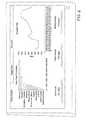
- FIG. 3shows an exemplary relational chart according to embodiments of the invention
- FIGS. 4 a and 4 bshow illustrative circuits according to embodiments of the invention
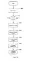
- FIG. 5shows a flow chart illustrating the power monitoring process according to embodiments of the invention
- FIG. 6shows a flow chart illustrating the switching decision process according to some of the various embodiments of the invention
- FIGS. 7-17show nodes according to various embodiments of the present invention.
- FIG. 18shows a remote control for use in the system according to embodiments of the invention.
- FIGS. 19 a - 19 bshow flow charts illustrating the formulation of an intelligent control policy according to embodiments of the invention
- FIG. 20shows a control node according to embodiments of the invention
- FIG. 21shows an illustrative display according to embodiments of the invention.
- Embodiments of the present inventionmay be directed to an energy network for monitoring, controlling, and understanding the energy profile of a home, business, or other structure or power network.
- Other embodimentsmay be directed to an online service allowing users to share experiences and information, as well as compare or compete, in a community-based environment.
- FIG. 1shows a relational chart according to embodiments of the invention.
- a home energy network 10may be composed of a controller 100 and a distributed network of power monitoring and control nodes 101 - 106 .
- the nodesmay communicate with the controller, any optional repeaters, and each other via a network.
- the controller 100may be composed of a single base station with a display, or may be separated into: a base station to manage data storage and communication, and an interface console with display, buttons, LCD touchscreen, or other control elements.
- the controllermay be separated into a separate node control device and a display device.
- the user interface elementsmay be separate from both the node control device and the display device, such as on a computer, a handheld device (e.g., a cell phone, tablet computer, etc), or in any other type of device.
- Control, display, and interface functionsmay also be distributed amongst devices in the home energy network or even outside of the energy network on a public or private network such as the Internet.
- the controllermay be capable of communicating with a server 120 on the Internet 110 .
- Internet 110may also be a public or private network other than the Internet.
- the controller 100may send either raw data gathered from the nodes or processed/aggregated data to the remote server 120 .
- a display unitmay function as the “dashboard” for viewing data visualizations and interacting with the system.
- this display unitcould be a stand-alone controller, a display and input device, or just a display device.
- the display unitmay be wall mounted, handheld, or freestanding.
- the display unitmay contain components such as temperature sensors (thermocouple or thermistors), occupancy sensors, wireless signal detectors, RFID sensors, barcode or magnetic card sensors, biometric sensors, or any other sensor known to one of ordinary skill in the art.
- the displaymay be duplicated on a personal computer, through a website on the Internet, on a node or appliance connected to the network or Internet, on a mobile device connected to the network, or to any other device connected to the Internet.
- the display unitmay also be capable of wireless or wired transmission, utilizing any of the transmission protocols described herein or known to those of skill in the art.
- FIG. 3depicts a relational chart according to embodiments of the invention.
- System 30shows an example home energy network according to an embodiment of the invention.
- nodesmay also be embedded directly within appliances and devices, embedded directly into the wiring system of the home or building itself, or be devices able to connect to the various appliances and devices, as well as the power network in the home or building as more fully described below.
- appliances and devices that may be excluded from automated switchingare shown in italics and parentheses, however the exclusion of devices from the control of the controller 300 is purely optional.
- Groups 310 , 320 , and 330are illustrative groupings of nodes that are individually controllable by controller 300 .
- Media center group 322is illustrative of nested sub-groupings possible by the hierarchical structure of groups according to various aspects of the present invention.
- groupsmay be created through the use of tagging.
- Tagsmay be keywords or terms associated with or assigned to devices, thus describing the device and enabling a keyword-based grouping of the device with other devices.
- Tagsmay be chosen from a predefined list or added manually by a user or by the system itself. Tags may also be added to the predefined list, or to various devices automatically by the user community described herein.
- aspects of the inventioncontemplate devices having multiple assigned tags so that the device may belong to any number of groups at the same time, and be controlled and monitored accordingly.
- Various repeaters 304may be used in embodiments of the present invention in order to extend the reach of controller 300 to distant nodes. Further, according to some embodiments the controller may be separate from a dashboard 302 , as described more fully herein.
- Some embodiments of the inventionmay connect to an Internet 350 , which may consist of any type of public or private network.
- the power monitoring and control nodesmay be packaged in the form of common household electrical fixtures: outlets, switches, dimmers, power strips, thermostats, bulb sockets, and any other form of fixture or power-related device known to those of skill in the art.
- Nodesmay also take the form of more industrial or commercial electrical fixtures known to those in the art.
- Nodesmay be directed to any international standard known to those in the art.
- Nodesmay be packaged as clamp-on current transducers to monitor current in any wire, such as the power cord for an appliance or device.
- Nodesmay also be installed in the circuit breaker box in the form of circuit breakers, clamp-on current transducers on each circuit, or clamp-on current transducers monitoring the main electrical feed in a home or business.
- Nodescan also be embedded in appliances, devices, light fixtures, other data acquisition or monitoring systems, or any other power consuming or providing device known to those of skill in the art.
- a nodemay be composed of an electronic circuit, such as a logging and control circuit, and application-specific packaging.
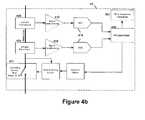
- FIG. 4 ashows an illustrative circuit according to one of the various embodiments.
- FIG. 4 bshows an alternate illustrative circuit according to another of the various embodiments.
- the circuit 40may contain a microprocessor 400 and may be capable of measuring and recording electrical current and voltage; deriving, processing, and storing power data; and communicating power data over the network.
- the circuitmay monitor the current and voltage via a voltage transducer 404 and a current transducer 406 .
- Those measurementsmay then be fed through to signal conditioners 408 and 410 and into an analog-to-digital conversion circuit (ADC) 414 via a multiplexer (MUX) 412 .
- ADCanalog-to-digital conversion circuit
- MUXmultiplexer
- the digitally converted signalmay then be interpreted by microprocessor 400 .
- the circuitmay also be capable of controlling an attached electrical device by switching the power to said device or controlling the amount of power received by the device, and of communicating the switch state or power consumption level over the network. Communication of information to the network may be accomplished through a network transceiver 420 . Nodes embedded in an appliance or other device may be able to control that devices power consumption and switch state, and be able to communicate those variables over the network.
- Nodesmay additionally contain one or more temperature sensors, such as a thermocouple of thermistor, or any of the other types and kinds of sensors mentioned herein. Nodes may also be wired in other various configurations or using other circuitry as will be appreciated by those of skill in the art. According to other aspects of the invention, nodes and other devices in the home energy network may also monitor their own power consumption and report that information to the network and user.
- temperature sensorssuch as a thermocouple of thermistor
- FIG. 5is a flow chart illustrating the power monitoring process according to some of the various embodiments of the invention.
- this methodmay be utilized by the various nodes in order to determine and communicate power information to other devices on the network.
- the nodemay first capture and measure the waveforms of both the voltage, step 510 , and current, step 511 , passing through the node. Those voltage and current data may then be combined into a power factor value in step 512 . After integrating the power values at step 514 , the node may accumulate 516 and filter 518 collected data prior to transmission to the network at step 520 .
- accumulation and filtering stepsare not necessary, and the node may directly send monitored data without any internal processing of that data, these steps may be omitted in some embodiments. In other various embodiments, additional steps may be added, some of which may relate to further preprocessing of data before transmittal.
- switchingmay be accomplished via a switching device 402 .
- This devicemay be a relay, triac, transistor, semiconductor, or other component.
- Switching actionsmay be performed either in response to a command received over the network or via predefined conditions and behaviors stored or written internally on the circuit.
- Switching circuitrymay also be enabled to change the level of power being sent to the device or appliance, beyond mere on and off states, such that any conceivable power level may be set by the switching circuitry.
- the predefined conditionsmay have been stored internally before installation or written to internal storage, after installation, by either a controller or other application connected to the network.
- Predefined conditionsmay include the node sensing a power surge or spike, a new appliance or device being plugged in, an appliance or device entering standby mode, or an indication that the appliance or other power consuming or providing device has been moved.
- eachmay be treated as an individually addressable node on the network, can be controlled individually, can be mapped and identified individually, and can detect whether an individual appliance or device is plugged in, switched on or off, in an active or standby mode, or any other state information, such as a reduced power mode.
- Embodiments of the inventionmay contemplate the various components of the invention being either directly connected as described herein, or indirectly connected through additional components or wiring systems. It should be easily realized to those of ordinary skill in the art that some of these indirect connections may be through other circuits, transistors, capacitors, networks, additional nodes or intervening devices, computers, intelligent switching or connecting systems, power networks or grids, electrical wiring, wireless protocols or technologies, or any other method of causing two components to communicate. As will be appreciated by those of ordinary skill in the art, this indirect connection and communication aspect may be applied to any of the aspects and embodiments of the invention described herein.
- FIG. 6is a flow chart illustrating the switching decision process according to some of the various embodiments of the invention.
- this methodmay be implemented by the various nodes in order to determine when to switch power to or from a connected device, or when to change the level of power going to the device.
- commandsmay be sent to the node in order to instruct the node to switch a power state on or to switch a power state off.
- the nodemay receive these commands and place them in internal readable memory, such as a buffer, register, or other storage medium.
- Some aspectsconsider a timed loop in which the commands are read from storage upon the lapse of a time interval, such as a system clock tick, and then executing the command upon reading, such as in step 610 .
- the nodemay check to see if any commands have been sent to the node, either by checking internal readable memory or by other means. Alternatively, the node may immediately act upon receipt of the commands. If a change state command has been sent to the node, the node may then change the state of the switching circuit at step 612 . After commands are checked and switches are adjusted (if necessary), the system then may measure current and voltage being transmitted through the node at step 614 . This may serve as a check that the proper switching state has been achieved or, in the case that throughput is being regulated at various levels, that the proper level of current or voltage is being controlled by the node.
- the collected datamay then be either stored internally or transmitted to devices connected on the network at step 616 , for either further analysis, local or system-wide diagnostics, or any other purpose disclosed herein.
- the systemmay then have a delay period 618 , either predetermined, programmed, selected, or dependent upon other factors, before checking for commands again.
- Other embodiments and aspects of the inventionmay use a process similar to that in FIG. 6 for controlling the level of voltage or current being passed through the node, or other power level controls described herein.
- nodesmay be configured to communicate stored or real-time power data and internal switching states at regular or irregular intervals, when certain optional conditions are met, or when polled. Polling may be performed by the controller or repeater, a computer connected to the network, a mobile device, a remote control, a computer or server connected to the network through a wide-area network such as the Internet, or any other nodes or network connected device.
- Regular intervalsmay be on the order of less than a second, or one or more seconds, minutes, hours, days, weeks, months, or years.
- Irregular intervalsmay be random or change over time; for example, when a node is reset by a user or system command, or detects a new appliance or device plugged in, or senses activity in a connected appliance or device, the node may initially send a constant stream of data for a short period of time and then send data less often as time passes. The change in interval length may occur in a linear, nonlinear, exponential, stepwise, or arbitrary fashion. Intervals may be synchronous or asynchronous with other nodes. Other aspects contemplate a manual initiation of the polling procedure by a user through the controller, dashboard, a remote device connected to the network through a wide-area network such as the Internet, or any user interface described herein.
- nodesmay communicate power data, switching state, status data, or any other sensor information to controllers, displays, other nodes, or any other device connected to the network, continually, intermittently, or when predefined conditions are met.
- Predefined conditions for the communication of datamay include a user override event, a switch or button activation (on either the node or device connected to the node) by the user, a power surge or spike, an appliance or device being plugged in to an outlet, a light bulb burning out, a certain instantaneous or average power level on an attached appliance or device being reached, a certain quantity of W-hr or kW-hr consumed by an attached appliance or device, or standby or active mode being detected in an attached device.
- Other types of data and predefined conditions available to the systemwill be appreciated by those in the art.
- Portsmay be any type of device, communications bus, network connection, or other device that allows or provides communication from the node to any other component or device, whether in the described invention or beyond.
- Processorsmay consist of circuitry, conventional processors, registers, calculators, algorithms, subroutines, or any other method of analyzing or manipulating data.
- Switchesmay be any of the types of switches described above, or further herein, such as a circuit to enable or disable the flow of power.
- Memory modulesmay consist of any type of memory device, such as random-access memory, read-only memory, flash memory chips, processor registers, caches, hard disks, readable or writable optical or tape storage, capacitors, other circuitry, or any other type of device known to those of skill in the art.
- FIG. 7illustrates an electrical outlet node with an integrated logging and control circuit according to various embodiments of the present invention.
- This nodemay consist primarily of a monitoring and control unit 702 , connected to a printed circuit board 704 and an on/off button 706 .
- the nodepreferably fits in a standard junction box 710 , or alternatively may replace the junction box, and may be connected to the home or office wiring 720 .
- each receptaclemay be individually monitored and/or switched.
- Button 706may allow a user to conduct a temporary override of the node, overriding the energy network system as more fully described below.
- buttons 708 and 709 in the exemplary FIG. 7may provide a button for each of the outlets on a receptacle, such as outlets 708 and 709 in the exemplary FIG. 7 .
- the buttonmay be replaced with a switch, dimmer, or other mechanism for controlling the node.
- Receptaclesindividually or together, may contain a switch or other sensor to detect when an appliance or device is plugged in (as in 730 ), when the device or appliance is drawing power, or when the device or appliance has entered a standby or other mode.
- the receptaclemay be configured to automatically switch off power in the absence of anything plugged in. This aspect of the invention acts as a safety feature to reduce the risk of electrocution inherent in any electrical fixture (e.g., when a child inserts a finger into an outlet).
- the nodemay also contain a location-determining sensor.
- the sensormay be based upon global positioning system (GPS) technology, the triangulation of wireless signals, powerline networking, other network-based location technology, or any other location-based technology, or manually input into the system.
- GPSglobal positioning system
- the nodemay transmit its location along with any information about the controlled device or appliance and monitoring and control data to the network for use by the system.
- the nodesmay interpret or acquire control signals or commands directed to the location the node is presently connected.
- the nodemay also contain appliance or device determining sensors. These sensors may be based upon radio frequency identification (RFID) technology, other electronic signatures or identifications emanating from the device or appliance, a power signature or profile of the appliance or device, or a manual or automatic pairing process between the appliance or device and the node.
- RFIDradio frequency identification
- the nodemay transmit the identity of the connected appliance or device, along with any other information previously described, to the network for use by the system.
- the nodesmay interpret or acquire control signals or commands directed to the type of appliance or device connected, or the specific appliance or device connected.
- FIG. 8illustrates an electrical wall switch node with an integrated logging and control circuit according to various embodiments of the present invention.
- This nodemay consist primarily of a monitoring and control unit 802 , connected to a printed circuit board 804 and an on/off switch lever 806 .
- This nodepreferably fits in a standard junction box 810 , or alternatively replaces the junction box, and is connected to the home or office wiring 820 .
- the junction boxmay contain multiple switch levers.
- the switch lever 806may be replaced with a dimmer switch or other power switching mechanisms known to those in the art.
- the wall switch nodemay additionally contain an internal switch or other sensor to detect when an appliance or device is plugged into an outlet controlled by the wall switch node, when the device or appliance is drawing power from the outlet, or when the device or appliance has entered a standby or other mode.
- the nodemay be configured to automatically switch off power to the outlet controlled by the wall switch node in the absence of anything plugged in.
- the inline outlet nodemay also contain a location-determining sensor.
- the sensormay be based upon global positioning system (GPS) technology, the triangulation of wireless signals, powerline networking, other network-based location technology, or any other location-based technology, or manually input into the system.
- the nodemay transmit its location along with any information about the controlled device or appliance and monitoring and control data to the network for use by the system.
- the nodesmay interpret or acquire control signals or commands directed to the location the node is presently connected.
- the nodemay also contain appliance or device determining sensors. These sensors may be based upon radio frequency identification (RFID) technology, other electronic signatures or identifications emanating from the device or appliance, a power signature or profile of the appliance or device, or a manual or automatic pairing process between the appliance or device and the node.
- RFIDradio frequency identification
- the nodemay transmit the identity of the connected appliance or device, along with any other information previously described, to the network for use by the system.
- the nodesmay interpret or acquire control signals or commands directed to the type of appliance or device connected, or the specific appliance or device connected.
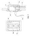
- FIG. 9illustrates an inline outlet node with an embedded logging and control circuit according to various embodiments of the present invention.
- the plug-in node 910may consist primarily of an internal monitoring and control unit and an on/off button 912 .
- the nodemay plug into a standard outlet 920 and provides a receptacle to receive a plug of a device or appliance 930 .
- the inline outlet nodemay have multiple receptacles in which to plug multiple devices or appliances, while the node itself plugs into only one outlet socket.
- the inline outlet nodemay have multiple receptacles in which to plug multiple devices or appliances, while the node itself can plug into multiple outlet sockets.
- the number of receptacles on the nodemay equal the number of outlets the node plugs into, while in other aspects, there may be a disproportionate number of receptacles available and outlets used.
- each receptaclemay be individually monitored and/or switched.
- Button 912may allow a user to conduct a temporary override of the node, overriding the energy network system as more fully described below.
- Other embodiments of the inventionmay provide a button for each of the receptacles available for devices or appliances. In other embodiments, the button may be replaced with a switch, dimmer, or other mechanism for controlling the node.
- Receptaclesindividually or together, may contain a switch or other sensor to detect when an appliance or device is plugged in, when the device or appliance is drawing power, or when the device or appliance has entered a standby or other mode.
- the receptaclemay be configured to automatically switch off power in the absence of anything plugged in.
- the inline outlet nodemay also contain a location-determining sensor.
- the sensormay be based upon global positioning system (GPS) technology, the triangulation of wireless signals, powerline networking, other network-based location technology, or any other location-based technology.
- GPSglobal positioning system
- the nodemay transmit its location along with any information about the controlled device or appliance and monitoring and control data to the network for use by the system.
- the nodesmay interpret or acquire control signals or commands directed to the location the node is presently connected.
- the inline outlet nodemay also contain appliance or device determining sensors. These sensors may be based upon radio frequency identification (RFID) technology, other electronic signatures or identifications emanating from the device or appliance, a power signature or profile of the appliance or device, or a manual or automatic pairing process between the appliance or device and the node.
- RFIDradio frequency identification
- the nodemay transmit the identity of the connected appliance or device, along with any other information previously described, to the network for use by the system.
- the nodesmay interpret or acquire control signals or commands directed to the type of appliance or device connected, or the specific appliance or device connected.
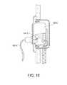
- FIG. 10illustrates a power strip node with an embedded logging and control circuit according to various embodiments of the present invention.
- the power strip node 1010may consist primarily of an internal monitoring and control unit, an on/off button 1012 , and multiple outlet receptacles 1014 - 1016 .
- the nodemay plug into a standard outlet using a fixed cord 1020 and provides the multiple receptacles to receive plugs of devices or appliances 1032 - 1034 .
- the power strip nodemay have a varying number of receptacles in which to plug multiple devices or appliances, such as 2, 4, 6, 8, or 10.
- power strip nodesmay be plugged into other power strip nodes in order to create more available outlet receptacles.
- the first power strip nodemay recognize a subsequent power strip node plugged into a receptacle and pass control and monitoring information and commands through to the subsequent power strip and back to the network.
- each receptaclemay be individually monitored and/or switched.
- Button 1012may allow a user to conduct a temporary override of the node, overriding the energy network system as more fully described below.
- Other embodiments of the inventionmay provide a button for each of the receptacles available for devices or appliances. In other embodiments, the button may be replaced with a switch, dimmer, or other mechanism for controlling the node.
- Receptaclesindividually or together, may contain a switch or other sensor to detect when an appliance or device is plugged in, when the device or appliance is drawing power, or when the device or appliance has entered a standby or other mode.
- the receptaclemay be configured to automatically switch off power in the absence of anything plugged in.
- the nodemay also contain a location-determining sensor.
- the sensormay be based upon global positioning system (GPS) technology, the triangulation of wireless signals, powerline networking, other network-based location technology, or any other location-based technology.
- GPSglobal positioning system
- the nodemay transmit its location along with any information about the controlled device or appliance and monitoring and control data to the network for use by the system.
- the nodesmay interpret or acquire control signals or commands directed to the location the node is presently connected.
- the nodemay also contain appliance or device determining sensors. These sensors may be based upon radio frequency identification (RFID) technology, other electronic signatures or identifications emanating from the device or appliance, a power signature or profile of the appliance or device, or a manual or automatic pairing process between the appliance or device and the node.
- RFIDradio frequency identification
- the nodemay transmit the identity of the connected appliance or device, along with any other information previously described, to the network for use by the system.
- the nodesmay interpret or acquire control signals or commands directed to the type of appliance or device connected, or the specific appliance or device connected.
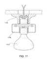
- FIG. 11illustrates a bulb socket node with an embedded logging and control circuit according to various embodiments of the present invention.
- the bulb socket node 1110may consist primarily of an internal monitoring and control unit, an optional on/off button, and a bulb receptacle.
- the nodemay plug into a standard light fixture 1120 and provides a standard bulb receptacle to receive a light bulb 1130 .
- the bulb socket nodemay have a two or more light bulb receptacles in which to plug multiple light bulbs. In those embodiments, each receptacle may be individually monitored and/or switched.
- An optional button, pull-chain, or other switchmay allow a user to conduct a temporary override of the node, overriding the energy network system as more fully described below.
- Other embodiments of the inventionmay provide a button, pull-chain, or other switch for each of the receptacles available for light bulbs.
- Receptaclesindividually or together, may contain a switch or other sensor to detect when a bulb or other device is plugged in, when the bulb or other device is drawing power, or when the bulb or other device has entered a standby or other mode.
- the receptaclemay be configured to automatically switch off power in the absence of anything plugged in.
- the nodemay also be able to monitor, measure, and control the intensity of light emanating from the attached light bulb(s).
- the nodemay also contain a light-sensing sensor.
- the sensormay be based upon photo-multiplier tubes, photo-diodes, photo-transistors, CdS photocells, or other light-sensing devices known to those in the art.
- the nodemay transmit sensed light information along with any information about the controlled bulb or device and monitoring and control data to the network for use by the system.
- the nodemay adjust the intensity of the light emitting from the light bulb based upon data gathered from the light-sensing sensor.
- user settings, the time of day, environmental factors such as daylight hoursare also taken into account by the node and system.
- the nodemay also contain a location-determining sensor.
- the sensormay be based upon global positioning system (GPS) technology, the triangulation of wireless signals, powerline networking, other network-based location technology, or any other location-based technology.
- GPSglobal positioning system
- the nodemay transmit its location along with any information about the controlled bulb or device and monitoring and control data to the network for use by the system.
- the nodesmay interpret or acquire control signals or commands directed to the location the node is presently connected.
- the nodemay also contain bulb or device determining sensors. These sensors may be based upon radio frequency identification (RFID) technology, other electronic signatures or identifications emanating from the device or bulb, a power signature or profile of the bulb or device, or a manual or automatic pairing process between the bulb or device and the node.
- RFIDradio frequency identification
- the nodemay transmit the identity of the connected bulb or device, along with any other information previously described, to the network for use by the system.
- the nodesmay interpret or acquire control signals or commands directed to the type of bulb or device connected, or the specific bulb or device connected.
- FIG. 12illustrates a thermostat node with an embedded logging and control circuit according to various embodiments of the present invention.
- the thermostat nodemay consist primarily of an internal monitoring and control unit 1212 attached to or enclosed in a wall-mounted thermostat 1210 .
- the thermostat nodemay not power the HVAC systems they control, electrical power is not necessarily monitored in this node.
- the thermostat nodemay be paired with another corresponding node (such as a circuit breaker node, a clamp-on current transducer node, or any other hardwired node) in order to monitor and control power going into the HVAC system controlled by the thermostat node.
- the thermostatmay record and transmit its user-defined settings (e.g., temperature set-points) and data on when it calls for heating/cooling from the HVAC system.
- the thermostat's settingsmay be modified remotely by the controller.
- a thermostat nodemay be connected or attached to a water heater. This thermostat may be similar to that in FIG. 12 .
- a water heater thermostat nodemay be able to control the switching of the electronic control portion of a gas-fired water heater, the switching of the heating element of an electric water heater, the switching of an entire electric water heater, or modifying the setpoint for the internal water temperature of a water heater. In the latter event, the water may be maintained at a minimum temperature in order to ensure warm water availability at all times, while only adjusting the temperature to a nominal hot level during typical times of use.
- FIG. 13illustrates a circuit breaker node with an embedded logging and control circuit according to various embodiments of the present invention.
- the circuit breaker nodemay consist primarily of an internal monitoring and control unit 1312 , attached to or embedded in a circuit breaker housing 1310 .
- the nodemay plug into a standard breaker box using a contacts on the housing 1310 .
- a switch or button on the housing 1310may allow a user to conduct a temporary override of the node, overriding the energy network system as more fully described below.
- the internal monitoring and control unit 1312may contain a switch or other sensor to detect when appliances or devices are plugged in to the circuit, when devices or appliances are drawing power from the circuit, or when devices or appliances have entered a standby or other mode on the circuit.
- the circuit breaker nodemay be configured to automatically switch off power to the circuit in the absence of anything plugged in.
- the nodemay also contain a location-determining sensor.
- the sensormay be based upon global positioning system (GPS) technology, the triangulation of wireless signals, powerline networking, other network-based location technology, or any other location-based technology, or manually input into the system.
- GPSglobal positioning system
- the nodemay transmit its location along with any information about the controlled device or appliance and monitoring and control data to the network for use by the system.
- the nodesmay interpret or acquire control signals or commands directed to the location the node is presently connected.
- the nodemay also contain appliance or device determining sensors. These sensors may be based upon radio frequency identification (RFID) technology, other electronic signatures or identifications emanating from the device or appliance, a power signature or profile of the appliance or device, or a manual or automatic pairing process between the appliance or device and the node.
- RFIDradio frequency identification
- the nodemay transmit the identity of the connected appliance or device, along with any other information previously described, to the network for use by the system.
- the nodesmay interpret or acquire control signals or commands directed to the type of appliance or device connected, or the specific appliance or device connected.
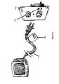
- FIG. 14illustrates a clamp-on current transducer node according to various embodiments of the present invention.
- the clamp-on current transducer node 1410may consist primarily of an internal monitoring and communication unit and an on/off button 1412 .
- the nodemay be clamped on to a power line/wire 1420 .
- the clamp-on current transducer nodemay monitor current in any wire, including the main electrical feed in a home or office, feeds from alternative sources of energy, a single circuit inside or emerging from a breaker box, or any hardwired appliance or device.
- alternative sources of energymay include generators; photovoltaic or other solar power systems; and wind, hydroelectric, and geothermal power systems.
- this nodemay not have switching capability.
- the nodemay be paired with another corresponding node (such as a circuit breaker node or any other control node) in order to control power going through wire 1420 .
- These corresponding nodesmay communicate information with each other, or with a controller or other device on the network, in order to control the power going through wire 1420 .
- the button 1412may act in concert with any corresponding nodes to allow a user to conduct a temporary override of the node, overriding the energy network system as more fully described below.
- the clamp-on current transducer nodemay be powered separately via batteries or power leads.
- the nodemay also contain a location-determining sensor.
- the sensormay be based upon global positioning system (GPS) technology, the triangulation of wireless signals, powerline networking, other network-based location technology, or any other location-based technology.
- GPSglobal positioning system
- the nodemay transmit its location along with any information about the controlled device or appliance and monitoring and control data to the network for use by the system.
- the nodesmay interpret or acquire control signals or commands directed to the location the node is presently connected.
- the nodemay also contain appliance or device determining sensors. These sensors may be based upon radio frequency identification (RFID) technology, other electronic signatures or identifications emanating from the device or appliance, a power signature or profile of the appliance or device, or a manual or automatic pairing process between the appliance or device and the node.
- RFIDradio frequency identification
- the nodemay transmit the identity of any appliance or device powered by wire 1420 , along with any other information previously described, to the network for use by the system.
- the nodesmay interpret or acquire control signals or commands directed to the category of appliance or device connected, such as a consumer electronics device or lighting device, or the specific appliance or device connected, such as the DVD player or microwave.
- FIG. 15illustrates a pass-through node with an embedded logging and communications circuit according to various embodiments of the present invention.
- the pass-through node 1510may consist primarily of an internal monitoring and communication unit 1512 and an optional on/off button.
- the nodemay be positioned between a power plug 1520 and a standard electrical outlet 1530 .
- the pass-through section of the nodeis very thin to minimize the effective amount of length lost by the plug's blades 1522 .
- the appliance or device's power pluginserts normally into a standard receptacle.
- the nodemay contain a monitoring and communication circuit that makes contact with one or more pins or blades, and/or a circuit containing one or more windings of a conductor around one or more pins or blades. These circuits enable the pass-through node to measure the voltage and current running to the appliance or device without connecting measurement equipment in series with the power plug.
- the pass-through nodemay have multiple receptacles in which to plug multiple devices or appliances through.
- each pass-through receptaclemay be individually monitored. In aspects of the invention, this node may not have switching capability.
- the nodemay be paired with another corresponding node (such as a circuit breaker node or any other control node) in order to control the attached appliance or device.
- corresponding nodesmay communicate information with each other, or with a controller or other device on the network, in order to control the attached appliance or device.
- an optional buttonmay act in concert with any corresponding nodes to allow a user to conduct a temporary override of the node, overriding the energy network system as more fully described below.
- the pass-through nodemay be powered separately via batteries or through the connection with the standard outlet and appliance or device's completed circuit.
- buttonsmay be replaced with a switch, dimmer, or other mechanism for controlling the attached appliance or device.
- Receptaclesindividually or together, may contain a switch or other sensor to detect when an appliance or device is plugged in, when the device or appliance is drawing power, or when the device or appliance has entered a standby or other mode.
- the nodemay be configured to automatically switch off power in the absence of anything plugged in, through collaboration with a corresponding control node.
- the pass-through nodemay also contain a location-determining sensor.
- the sensormay be based upon global positioning system (GPS) technology, the triangulation of wireless signals, powerline networking, other network-based location technology, or any other location-based technology.
- GPSglobal positioning system
- the nodemay transmit its location along with any information about the controlled device or appliance and monitoring and control data to the network for use by the system.
- the nodesmay interpret or acquire control signals or commands directed to the location the node is presently connected.
- the pass-through nodemay also contain appliance or device determining sensors. These sensors may be based upon radio frequency identification (RFID) technology, other electronic signatures or identifications emanating from the device or appliance, a power signature or profile of the appliance or device, or a manual or automatic pairing process between the appliance or device and the node.
- RFIDradio frequency identification
- the nodemay transmit the identity of the connected appliance or device, along with any other information previously described, to the network for use by the system.
- the nodesmay interpret or acquire control signals or commands directed to the type of appliance or device connected, or the specific appliance or device connected.
- other node typesmay include nodes that provide an interface with independent data acquisition, monitoring, or control systems, such as those that manage solar power and battery storage systems, nodes that monitor natural gas devices and pipelines entering the home or business, and other nodes embedded within appliances or devices.
- Other types of nodes that may be availableinclude natural gas and water monitoring nodes, that may log the amount of utility brought into the system, the amount of the utility consumed, and how the utility was consumed.
- Still other nodesmay monitor flow, temperature, pressure, or other information regarding utility usage points such as sinks, showers, bathtubs, water heaters, refrigerators, dishwashers, sprinklers, clothes washing machines, outdoor hoses, swimming pools, boilers, stoves, ovens, gas-fired air conditioners and chillers, fireplaces, forced air and radiant heaters, as well as any other device known to those in the art.
- Still other types of nodesmay conduct health and air quality monitoring. Nodes could monitor levels of dust, volatile organic compounds, carbon monoxide, mold, and other allergens or particles known to those in the art and report these levels to the controller. These measurement capabilities could be built into dedicated nodes or other existing node types.
- Some nodesmay also integrate with plug-in electric and hybrid-electric vehicles (cars, scooters, Segways, etc.), or any alternative energy-powered transportation devices known to those in the art.
- the nodescould track charging activity and include the vehicle in analysis of home power usage or travel usage.
- nodesmay communicate with each other, the controller, and other devices listed herein via a low-power wireless, powerline network, or any other network system or technology known to those in the art.
- the network topologymay be star, tree, or mesh.
- Example wireless network standardsinclude ZigBee and Z-Wave. Messages are transmitted in XML, CSV, or other text or binary format. Some nodes may operate only as endpoints, while others may operate as repeaters.
- Various other networksmay be implemented in accordance with embodiments of the invention, including a wired or wireless local area network (LAN) and a wide area network (WAN), wireless personal area network (PAN) and other types of networks.
- LANlocal area network
- WANwide area network
- PANpersonal area network
- computers and nodesWhen used in a LAN networking environment, computers and nodes may be connected to the LAN through a network interface or adapter.
- computers or nodesWhen used in a WAN networking environment, computers or nodes typically include a modem or other communication mechanism. Modems may be internal or external, and may be connected to the system bus via the user-input interface, or other appropriate mechanism.
- Computers or nodesmay be connected over the Internet, an Intranet, Extranet, Ethernet, or any other system that provides communications.
- Some suitable communications protocolsmay include TCP/IP, UDP, or OSI for example.
- communications protocolsmay include Bluetooth, Zigbee, IrDa or other suitable protocol.
- components of the systemmay
- various security mechanisms and measuresmay be taken to provide secure access to these features by authorized users.
- Some aspects of the inventionmay incorporate the use of public and private keys, PIN codes, usernames and passwords, CAPTCHA key-phrases, virtual private networking, secure tunneling technologies, SSH or HTTPS protocols, dedicated lines, other encryption methods, or any of the vast other networking security and encryption features known by those of skill in the art.
- the relationship between nodes and controllers, user interfaces, computers, or other controlling devicesmay be characterized as a that of a client and a server.
- the servermay control, monitor, or update the clients, as well as other activities known to those in the art.
- the benefits and characteristics of a client-server relationshipwill be appreciated by those in the art.
- Other aspectsmay provide for the controllers and remote access devices, such as networked computers, internet websites, remote control devices, or any other device, to be that of a server and a client.
- the community based serversmay also act as a server where the controller may be a client. Other embodiments contemplate the reversal of these relationships.
- the above listed client-server relationshipsmay instead be characterized as a distributed computing network or system.
- all nodes, controllers, remote devices, and serversmay act in concert to effect processing, monitoring, and control required by the system.
- the benefits and characteristics of such a distributed computing networkwill be appreciated by those of skill in the art.
- control software for the home energy networkoperating within either the controller, or installed on a personal computer assigned the role of controller, automates the powering on and off (switching) of the individual nodes in the network.
- control software and controllermay further control the amount of current and voltage being allocated to each of the devices or appliances connected to any or all of the nodes in the network.
- Embodiments and aspects of the inventionthrough the implementation of these switching and control operations, may serve to conserve the electricity used by a customer's home or office while providing the user with as much convenience and control as possible.
- the automated switching behavior of the individual nodesis determined in software with a combination of user-defined inputs and system intelligence.
- User-defined inputsmay include an initial setup and ongoing adjustment(s) of user preferences using either the dashboard controller, personal computer, any device connected to the network (either locally or remotely), or a web interface.
- the types of data inputs provided by a usermay include but are not limited to:
- lifestyle preference characteristics or other datasuch data describing the general habits of users of the system, any comfort preferences of those users, and any desired goals to be reached from the use of the home energy network (such as cost savings, minimization of the environmental impact of energy consumption, or other goals);
- any other type of input typically associated with computer systemssuch as profile information, personal data, display preferences (such as interface skins).
- the home energy networkmay be set up, both initially and subsequently, in multiple different ways.
- an interactive remote controlsuch as the dashboard, a wireless interface, or a software application running on a computer or other device, may activate a “setup mode” on the remote control.
- the usermay then carry the remote control to each node to be configured, press a button or other selection object on the node to initiate a wireless handshake between the node and the remote control, and respond to the remote control's prompts about the location of the node and the appliance or device to be connected to the node.
- the individual nodesmay be plugged into the remote control or the remote control may be plugged into the individual nodes, directly.
- a plug-in configuration toolmay be used.
- the plug-in toolmay be plugged into each node to be configured.
- the plug-in toolmay electronically handshake or otherwise connect with the connected node, and determines the type of node connected and any other node identifying information (such as version number, serial number, other universally or locally unique information, or physical orientation of the node).
- the plug-in toolmay also optionally determine the category of device or appliance connected to the node or any other device or appliance identifying information (such as version number, serial number, or other universally or locally unique information).
- the plug-in toolmay send received configuration information to the controller through any networking technology contained herein.
- the plug-in toolhas a display
- the usercan select an option on the display (e.g., select from a list of rooms or zones that the user previously defined with the dashboard) or enter new information (e.g., with a miniature keyboard).
- the plug-in toolmay have been preconfigured (e.g., the user might use the dashboard to configure the tool to identify all nodes located in a certain room, plug the tool into each node in that room, then return to the dashboard to set up the next room/zone).
- the usermay manually log or configure the nodes attached to the home energy network.
- the nodesmay have letters, numbers, names, or other codes marked on them. These identification codes or markers may be unique to a given installation but not absolutely unique; a certain installation may use a system-wide identifier code. In other aspects, these identification codes are absolutely unique.
- a usermay fill out a form, noting the identification information on each node and where the node is or will be installed. A user may then enter the form information into the dashboard, a computer, a web interface, or other configuration device.
- the nodesmay be mapped prior to installation.
- a usermay begin a guided setup process (e.g., wizard) on a dashboard interface.
- the setup wizardmay prompt the user to select a specific node (based on type or specific node identification information) and decide where it will be installed and, optionally, what that node will be used for (which may be a specific assignment, “open outlet”, or other selection).
- the usermay then install the node.
- the usermay start the procedure over with a new node. In other variations of this procedure, multiple nodes may be simultaneously mapped and installed.
- each nodemay be hooked up to the dashboard, a computer, or other configuration device, whether directly or indirectly (such as through another node, a network, or an attached accessory).
- a usermay press a button on node in order to initiate a pairing and configuration handshake with the configuring device.
- the usermay then declare where the node will be installed and/or what will be connected, and marks the node accordingly (e.g., “living room wall” or “refrigerator”). The user repeats this procedure for all nodes to be installed.
- the nodesmay be configured using a barcode reader.
- the use of the barcode readermay be similar to the plug-in installation tool, but may read barcodes on nodes instead of plugging directly into the nodes.
- the barcodesmay be stickers affixed to nodes or printed directly on the nodes.
- nodesmay be previously configured. This may be the case with appliances that have embedded nodes and with inline nodes, detailed herein.
- RFID based tags or other self-identifying technologiesmay also be preconfigured to work seamlessly with a home energy network.
- the invention's data visualization toolsmay provide the user with graphical and numerical data, reporting the performance of these sources and systems, or calculating the savings in energy and cost if such systems were to be installed.
- the graphical user interfacemay prompt the user with requests for information about the house (i.e., number and type of windows, roofing type, and which direction they face) to make estimates of the heat losses or loads. It may also provide forms to easily input the data such as R- and U-values generated by on-site energy audits to provide a baseline for improvements and provide quantitative tools for evaluating them.
- sensorssuch as temperature, wind, or light detectors may also be integrated to provide a richer set of data for the display and analysis on the dashboard.
- the nodesmay communicate with the user to confine connection or registration on the network, indicate switching and monitoring status, or other node or network states.
- Methods of communicating with the usermay include: flashing multi-colored LEDs, either alone or in an array, affixed on visible parts of the nodes or, alternatively, on parts of the node normally hidden (e.g., between the node and a wall); sounds emanating from the device in the form of beeps, clicks, tones, polyphonic sounds, or recorded or synthesized voices; or richer displays such as LED, OLED, E-Ink, LCD, or other digital display technologies.
- the system or nodesmay communicate automation behaviors the user. This may include the full set of LED, sounds, displays, and other indicators mentioned above (for example, a node may blink or beep when a user override event is about to time-out, or when a node is about to change switch state according to its schedule). This may also include dimming or blinking attached lamps or light fixtures. For example, if the system detects that a room is not occupied, the lights might gradually dim before switching off. This would avoid the sudden switching that occurs with many motion detector-based light switches, and would give the user a chance to react. As another example, when a user puts a home or office into “sleep” mode, the system may dim or blink an attached light fixture to confirm the user's choice.
- appliances and devicesmay be grouped according to function, physical location, or any other useful grouping.
- a usermight create a “media center” group 322 that includes a TV, digital video recorder (DVR), DVD player, video game console, and stereo system, that should generally all be switched on as a single unit when the media center is in use.
- DVRdigital video recorder
- the groupmay be switched off to save power and eliminate “leak” currents.
- groupsmay also contain “excluded devices” as described below.
- these groupings of devicesmay be monitored as an entire entity instead of individually, should such functionality be desired.
- a stereo groupmay have its own monitoring statistics, such a group possibly containing a receiver, CD player, and amplifier.
- the groupingsmay be hierarchical in nature, allowing nested levels of groupings. In those aspects, different levels of groupings would allow broader or narrower, more specific, control of devices at the desire of the user.
- groupsmay be created through the use of tagging. Tags may be keywords or terms associated with or assigned to devices, thus describing the device and enabling a keyword-based grouping of the device with other devices.
- the tagging structure of the systemmay include any tagging elements well known to those in the art, such as those described in “The Hive Mind: Folksonomies and User-Based Tagging,” by Ellyssa Kroski, which is fully incorporated by reference herein.
- Tagsmay be chosen from a predefined list or added manually by a user or by the system itself. Tags may also be added to the predefined list, or to various devices automatically by the user community described herein. Aspects of the invention contemplate devices having multiple assigned tags so that the device may belong to any number of groups at the same time, and be controlled and monitored accordingly.
- a usermay classify certain appliances or devices as desirable for “parental control” and restrict their use by children.
- the systemcould restrict televisions, video game consoles, computers, or other entertainment devices, or any other desired device, from powering on during certain times of the day, or could limit those devices to being used for longer than a specified duration.
- the systemcould require a password to be input into the system, either through a mobile device, a computer, a controller or interface device, or through a keypad connected to or embedded in any node, before providing power to the device subject to parental control.
- parentsmay designate appliances/devices, nodes, or groups (e.g., rooms) as “monitored” and receive notifications about when the monitored items were used and for how long. Notifications may be regular repeating reports or may only occur when time/duration limits were exceeded. For example, if a parent restricts use of a video game console to two hours per day and to times between 4 pm and 11 pm, and the child violates those rules, the parent may be notified.
- embodiments of the systemmay attempt to track the appliance/device/node. For example, if a laptop computer is unplugged from a restricted outlet node, and the system detects that one or more “new” devices has been plugged in to another outlet node (whether in the same room/zone/group or elsewhere), the system may attempt to determine whether the “new” device (or which of several) is the restricted appliance/device. This attempt may include assuming the first “new” device plugged in after the restricted device was unplugged is the restricted device, or may involve inspecting the power profiles of one or more devices and comparing against the historical power profile associated with the restricted device.
- an inline monitoring node, identification node, or other mobile tag or nodemay be attached to the restricted item in a way that makes the node or tag's removal difficult.
- Thismay include mechanically fastening a node in place using a bolt, screw, set screw, lock, or clamp, or may include gluing or bonding a node or tag in place. With the node or tag effectively locked, the restricted item may be moved between outlets without affecting the monitoring or access controls.
- the systemmay configure initial settings based upon a self-diagnostic or assessment of the configuration of the network. There, the system may be able to determine the location and type of various nodes connected to the network, along with the identity of the devices or appliances connected through those nodes, in order to suggest or pre-configure settings, groups, sub-groups, and parental controls for the user.
- certain devicesmay be provided power at all times and may be excluded from automated switching by the system.
- a digital video recorderDVR
- the same rulesmay apply to personal computers, alarm clocks, and certain other appliances and devices. Appliances and devices such as those listed above may be automatically excluded from switching once they are connected to and identified by the system.
- userscan choose (via any previously mentioned or available interface, including a dashboard, a personal computer, or website) to override this behavior to include or exclude any individual appliance or device connected to the network.
- Usersmay also be able to set varying levels of exclusion for various devices. For example, while some devices may be completely excluded from control by the system, such as the DVR described above, other devices may be controlled to an exclusion level (or point) as defined by the user. In this example, the security lighting may be dimmed down to a certain level by the system, but not turned completely off. The same could be considered for computers able to be put in a sleep or hibernation mode, but without being turned off, or other devices as will be appreciated by those of ordinary skill in the art.
- FIG. 16is illustrative of an outlet node 1610 able to detect a plugged in device 1614 via a sensor 1612 in accordance with an embodiment of the invention.
- nodesmay detect appliances or devices through numerous methods, including but not limited to any previously mentioned method or either of the following:
- a switch triggered by the insertion of the plug into the outletmay be triggered by a cover plate that slides or pivots over the opening(s) in the receptacle, or via the blades and/or pins on the plug itself.
- One or more blades and/or pinsmay actuate a mechanical switch or an electrical contact, or may trigger an optical switch.
- An optical switchmay involve one or more blades or pins blocking light traveling between an emitter and a receiver, or may reflect light from an emitter to a receiver.
- the nodemay then send a network message to the controller, or any other device connected to the network, announcing the presence of the new device.
- the new devicemay then be identified and classified in the system. In some embodiments, this identification may be entered manually by the user in response to a prompt or series of prompts from the dashboard. In other embodiments, a variety of methods are available to automatically recognizing certain devices.
- an electronic handshake between the outlet node and the appliance or devicemay be used to recognize specific devices or appliances.
- an electronic handshake between the outlet node and an additional device attached to the appliance or devicesuch as: an inline adapter connected between the node and appliance or device; an electronic tag, such as an RFID tag, attached to the appliance or device and read by the outlet node when the tag is within a certain range may be used to recognize specific devices or appliances.
- FIG. 17is illustrative of a node capable of identifying an appliance through the use of an attached additional device, according to embodiments of the present invention.
- an outlet node 1710contains an RFID reader 1715 . The reader is able to scan an RFID tag 1725 attached to an appliance or device's cord 1720 , in order to identify the appliance or device.
- tagsmay be prepackaged and pre-labeled to correspond with typical household items such as computers, air conditioners, refrigerators, lamps, washing machines, televisions, and the like, and be easily attached as stickers or twist-ties on power cords or A/C adapters.
- the systemmay analyze the power consumption of the appliance or device over time to make an educated guess about its type or may be used to recognize specific devices or appliances.
- the systemmay also learn from analyzing the power signatures and consumption patterns of previously registered devices and appliances in order to better estimate the category or specific identity of newly connected appliances or devices.
- Further embodimentsconsider the system receiving updated heuristics or other identity estimation data from a remote server. In some of those embodiments, the server could create the updates based on information gathered from multiple energy network systems and from third parties, such as vendors of appliances or devices.
- the vendorsmay upload specific energy signature and power consumption information to the server, and through the server to the various energy network systems, in order to identify the specific model of device connected, and consequently the category and other information associated with that specific model of device or appliance.
- Some constituent elements of an energy signature or power consumption profilemay include the amount of power consumed upon startup of the device or appliance, amount of power consumed upon normal or prolonged operation of the device or appliance, resistance of the device or appliance at both startup and during prolonged or normal usage, amount of power or resistance measured from the device or appliance during standby or other reduced power or usage modes, the times of day at which the appliance or device is typically used (e.g., a television or DVD player may be used more frequently in the afternoons or evenings, whereas a coffee maker or espresso machine is more typically used in the mornings), the frequency at which a device or appliance is used, and what other devices are typically used in conjunction with or at the same time as the device or appliance.
- this datacan be used to improve the heuristic analysis for identifying new devices as they are connected to the system. For instance, if the system detects a pattern of high power consumption on a predictable duty cycle, the new appliance might be assumed to contain a compressor. If the appliance is attached to an outlet known to be in a bedroom, the appliance could be reasonably assumed to be a window-mounted air conditioner and not a refrigerator, and if the duty cycle or other characteristics correspond to those of a known make and model, the system could infer this as well.
- a power consumption profilemay be measured by first turning on an appliance or device.
- various characteristics of the devicemay be measured, such as the level of inrush of current, the current levels and durations during a startup sequence, and other current characteristics appreciated by those of skill in the art.
- Various inrush characteristicscould include a high sharp inrush (with a high capacitance but low impedance), a high extended inrush (with a high capacitance and high impedance), a low sharp inrush (with a low capacitance but high impedance), or a low extended inrush (with a low capacitance and low impedance).
- micro-scale power measurementsmay be taken, comprising calculating power factors during various operational modes of the device, calculating sinusoidal or other periodic fluctuations in current and voltage during those operational modes, and determining if the device uses a linear or switched-mode power supply.
- Macro-scale power measurementsmay also be available in the power profiling procedure, wherein the current and voltage amplitudes may be measured, the time cycling or periodic variation is current and voltage amplitudes are determined, any warm-up characteristics are discovered, or any other characteristics are discovered.
- individual nodes and groups of nodesmay switch power on and off, or to varying levels, to minimize or reduce the power consumption of attached appliances and devices, exercise parental controls, enhance safety, or meet other goals of the user, while continuing to provide the ordinary service and convenience to which the user is accustomed.
- Various aspectsmay apply this ability to all types of nodes.
- thermostatsmay be exempted from these switching controls, depending upon the settings of the system.
- Other embodimentsallow other devices to be exempted based upon the requirements and environment in which the system operates. For example, a system in a restaurant may exempt the industrial refrigerator from being switched.
- the switching controlmay extend to the individual receptacle and device level. Power savings may be achieved by switching off appliances and devices when they are not in use.
- Embodiments of the inventioncontemplate switching off both “active” loads like lights and air conditioners and “inactive” loads like electronic devices that “leak” current when off or in standby mode.
- Nodesmay switch power on and off, or to varying levels, in response to commands from the controller.
- the controllermay consult a schedule defined by the user, any predefined or previously configured settings (such as those described above, including automated setup), and may further adjust to or adapt to changing conditions sensed by the system. These conditions may include inputs from other nodes and sensors, such as buttons and switches, occupancy sensors, electrical activity on other nodes, or any other sensors disclosed herein.
- nodesmay also switch themselves off in response to power surges. This may be done automatically without a command from the controller if desired. In some aspects, the node may report the incident to the controller.
- Some embodiments of the present inventioncontemplate direct (and possibly two-way) communication with computers and other electronic devices, allowing the system to regulate power states and/or send commands and messages.
- the controllercould ask a computer, DVR, appliance, etc. to enter sleep mode, or low-power mode, but the device could choose how best to comply with the request, perform a number of actions before complying with the request, or choose to ignore the request.
- the controllercould trigger any possible reduced-power mode of a device or appliance, such that even a slight reduction in power could be realized in that mode. This would also allow the controller to “throttle” the power draw of certain devices, with more options than a simple binary on/off, and would enable power management of devices that are not suitable for physical power switching.
- An illustrative example of this conceptis the shutting off the heating element in an electric water heater (but not the pump).
- Another embodimentcontemplates the control of cooling using thermal masses, possibly in markets where electricity prices differ widely between peak and off-peak rates.
- the controllermay send a message to a chiller, air conditioner, or refrigerator.
- the appliancemay run the compressor to cool a thermal mass (e.g., chilled liquid, ice, or eutectic salts) while electricity is cheap (and cooling demands are probably lower, assuming this is at night).
- a thermal masse.g., chilled liquid, ice, or eutectic salts
- the controllermay send another message to the appliance, which blows air or circulates a fluid across the cold thermal mass, providing a cooling effect without running the compressor.
- the invention's automation capabilitiesmay also be integrated with passive building systems to improve or enhance their performance. Examples of how this may work according to various embodiments include:
- the automation of the pumpsmay incorporate information about the user's schedule and activity gathered by other systems monitored by the invention. For example, water heated during the day by a passive solar system may be held in reserve in an insulated holding tank if it is known that the user will not be home for some time, and pumped only when it is needed.
- the usermay define a schedule profile based on his typical usage pattern.
- a schedule profilemay define the switching, or other power regulating, behavior for individual appliances and devices and groups thereof.
- the media center in the user's living roommight typically be in use on weekdays from 6:00 a.m. to 9:00 a.m., and from 3:00 p.m. to 12:00 a.m. In that example, during the remaining hours—12:00 a.m. to 6:00 a.m. and 9:00 a.m. to 3:00 p.m.—the power to the media center can be switched off, eliminating all power consumption, without inconveniencing the user.
- This switchingmay be accomplished at the wall receptacle, by disabling an entire conventional power strip, or via a group of individual receptacles in a power strip node (as well as using any of the previously mentioned node devices). In the latter case, if a digital video recorder were included in the “media center” group but also specified as excluded from automated switching, the receptacle connected to the DVR would not be switched off.
- a window air conditioner in a room not typically occupied at nightsuch as a home office, and that is controlled via an integrated thermostat (as opposed to a central household thermostat) might be scheduled to turn off at night and turn back on in the morning, restarting early enough to cool the room before it is reoccupied.
- the various contemplated embodimentsdo not require users to conform to a rigid schedule to enjoy the benefits of the system as the system may be designed to be temporarily disabled, at the node/group level or system-wide, to accommodate changing user behavior.
- switching nodesmay be equipped with one or more buttons or other interface elements in order to temporarily cause the entire node or part of the node to toggle or adjust state—in other words, to switch off immediately, or to behave like a normal outlet, or wall switch, or to adjust the flow of power through that outlet.
- power monitoring and communications featurescontinue to operate during a temporary override. This feature is useful when a user wishes to override automated control, such as to activate an appliance or device for immediate use, or to immediately shut down an appliance or device normally scheduled to be on.
- FIG. 18is illustrative of a remote control being used to initiate a temporary override of a node or several nodes.
- the remote controlmay be tethered to the node or operate via the wireless network, like remote control 1810 .
- a remote controlmay be programmed to operate one of several nodes via a selection screen 1820 , or individual nodes like node 1832 .
- a remote controlmay useful for toggling the switch state of nodes that are obscured, blocked, or otherwise hard to reach.
- data gathered by the systemmay also be used by the controller, or other connected device, to improve the switching control schedule or settings without requiring direct input from the user.
- heuristic analysis of usage patternsmay improve the energy efficiency of a specific node.
- the systemcan apply that pattern to the schedule profile.
- their schedule profilecan be adjusted according to the observed usage pattern.
- the systemcan automatically generate one and either activate it or prompt the user to activate it.
- the systemmay detect when an appliance or device is not in use, or in reduced use, and automatically switch off power, or reduce power, to that device or appliance.
- Other aspectsmay contemplate determining ideal use or lack thereof by monitoring related device use, such as the other appliances in the same room or group, or other user power-usage habits. Referring to FIG. 19 a , some embodiments may accomplish this by first recording power consumption data and user override events at step 1900 . The system may then determine if there are any discernible patterns in power consumption over time on the targeted node at step 1910 . Here, the system may attempt to identify “modes,” where instantaneous or time-averaged power consumption is predictable.
- the systemthen separates modes into “standby/passive” and “active” states. Some aspects of the invention may provide for the separation of multiple active states at this step.
- the systemdetermines if the standby mode occurs at predictable time periods. In some aspects, these periods could be times of the day, certain days of the week, or other spans of time.
- the systemdetermines if user temporary override events occur with any predictability at step 1940 .
- the systemmay then calculate optimal modifications to any existing schedules or settings at step 1950 , and either implement those modifications directly or suggest implementation to the user at step 1960 .
- FIG. 19 billustrates another embodiment of the intelligent control policy.
- the systemmay record power consumption data at step 1900 .
- Some of this datamay include the analysis of turn-on characteristics 1902 , micro-scale power measurements 1904 , and macro-scale power measurements 1906 .
- Turn-on characteristicsmay include inrush current levels as further described herein, such as the high sharp inrush, the high extended inrush, the low sharp inrush, or the low extended inrush profiles. These and other inrush characteristics may be analyzed by the system along with a discernable electronic boot sequence, if it occurs, in the connected power-consuming device.
- the boot sequencemay be of a longer duration than the inrush characteristics, may begin after the inrush has completed, may occurs alongside the inrush characteristics, or any combination thereof.
- Micro-scale power measurementsmay be taken, comprising calculating power factors during various operational modes of the device, calculating sinusoidal or other periodic fluctuations in current and voltage during those operational modes, and determining if the device uses a linear or switched-mode power supply. These micro-scale power measurements could help determine if the connected device has an AC or DC power supply, or if the power supply is linear or switched-mode. Macro-scale power measurements may also be available in the power profiling procedure, wherein the current and voltage amplitudes may be measured, the time cycling or periodic variation is current and voltage amplitudes are determined, any warm-up characteristics are discovered, and any other characteristics are discovered. These characteristics may also be utilized in the identification of the category or specific identity of the connected device, as previously described herein.
- the systemmay use the recorded information in order to determine what mode the connected device is operating under, such as an active (on) state or inactive (standby) state. An off state may also exist. Based on this determination, the policy then either moves to step 1921 for active devices, or to step 1925 for inactive devices.
- the systemmay apply heuristics analysis to the recorded data, such as determining what type of power source, boot sequence, or other characteristics the connected device exhibits. Based on these heuristic analyses, the category or specific identity of the connected appliance or device is determined at step 1923 . Step 1924 then sends the device category or identity, as identifying information, to the setup process further detailed herein. The system may then periodically poll the connected device or node to determine if a state change occurs and continually monitor and improve the intelligent control policy.
- step 1932determines if the device is likely to be used within a set amount of time using information already known in the policy at 1931 , such as occupancy of the home or business, the mode or configuration profile currently in effect in the energy network, the time of day, or any other factors involved in the intelligent policy.
- the set amount of timemay be any amount of time, such as a minute, five minute interval, quarter or half-hour intervals, or multiples of hours. If the device is likely to be used, the device is left on in the inactive state at 1933 . If, on the other hand, the device is not likely to be used, step 1934 may switch off power to the device or adjust the device's schedule in the energy network.
- Step 1934may also further reduce the amount of power consumed by the device, or further control the device using any of the methods described herein.
- the connected devicemay be periodically polled at 1942 in order to determine if a state change occurs and continually monitor and improve the intelligent control policy.
- the systemmay also determine optimal modifications to any existing schedules or settings at step 1950 , and either implement those modifications at step 1960 . Implementation may occur as either a direct or automatic adjustment to the schedule at 1962 , or by recommending changes to the user at 1964 .
- the systemmay periodically poll the connected device, directly or through a node, to determine if a state change at the device has occurred. If a device's state has switched, like at step 1944 , the system may again determine the current state of the connected device at 1920 . This way, the system may continue to improve, modify itself, and adapt according to the usage habits recognized by the intelligent control policy.
- the systemmay use an attached battery in order to provide a buffer for balancing electricity generation and storage with the electricity usage determined from the monitoring nodes.
- the automated decoupling of instantaneous generation from instantaneous consumptionwill provide additional benefits to users.
- the energy automation systemmay be able to regulate flexible usage (i.e., electricity draws that can be shifted in time, or that are optional) such that, when taking the base (i.e., fixed) load into account, the overall load stays entirely within available stored power reserves or within a certain excess of stored reserves.
- the dashboardmay provide visualizations of the flow of electricity through a battery system (like a Prius), the grid, other sources, and various loads in the home/office.
- the dashboardmay provide visualizations of the batteries' level of charge over time.
- the systemmay provide visualizations/projections about the past, present, and future balance between battery draw, grid draw, and generation. For example, in the middle of a sunny summer day, a visualization might show electricity inputs from solar panels and the battery system, with the power flowing to a variety of loads.
- the visualizationmay show that the photovoltaic system's output is near its peak and meets the draw of the air conditioning system (and may allow for charging of the batteries).
- Embodiments of the systemalso contemplate the system may deciding to draw from reserves based on factors such as the price of electricity or when service interruptions are imminent. Other consider the system deciding to store energy within the battery system based on factors such as the price of electricity, loads on the power grid, and availability of various modes of generation (i.e., solar, wind, etc.). In other words, if electricity is more expensive during the day, it may make economic sense to charge the batteries from the grid at night.
- Embodiments of the systemmay maintain a minimum battery level for use in emergency situations. In such situations, the system might apply an “emergency” configuration profile, shutting off all appliances and devices (potentially including those normally excluded from switching) not necessary for safety and security.
- diesel and gasoline generatorsmay also be monitored and controlled. If the system determines, by reasons of cost, efficiency, or load, the generator is a preferable source of electricity for the building, the system may automatically switch from other sources of power to the generator.
- the systemmay automatically schedule the appliance, device, or group to switch off when the device is likely to be in standby. If a schedule already exists, the system may modify it. According to some aspects, scheduling may be based on statistical likelihood—for example, switching the device off during the time interval defined by a number of standard deviations of observations where the device was in the standby mode. Some aspects may test predictions by periodically modifying the various device schedules and power/configuration profiles and determining if more or less overrides occur as a result. If less overrides occur, the system may further modify the schedules and profiles. If more overrides occur, the system may revert to a prior schedule or profile.
- the systemmay modify the schedule for an appliance, device, or group to comport with the predicted override. This may be done with the intention of providing greater convenience to the user.
- the schedule adjustmentmay occur automatically or the user may be prompted to approve or modify the modification. Modifications may be determined statistically, as above, or otherwise.
- the systemmay also use prompts to advise users on opportunities to adjust their behavior to better conserve energy.
- embodiments of the inventionmay also automatically switch off, or reduce, power to an appliance, device, or group that has been in standby mode for a certain length of time.
- the node(s)may remain switched off until commanded to switch on (by the controller, based on automatic behavior or user command, or by a user through the temporary override button(s) on the node) or may periodically switch on to check the state of the connected appliance or device. In the latter case, the system may switch the power on and wait long enough to ensure that the appliance or device has reached a steady state.
- a battery chargermay be switched off while unused.
- the usermay push the override button to reactivate the charger.
- the nodeif the node is periodically switched on to check the state of the charger, the charger will begin charging and system will detect that the power consumption is greater than in standby mode, and the node will leave the power switched on. In either case, when the battery is charged and the charger enters standby mode, the node may automatically switch power off.
- aspects of the inventionmay also make use of data gathered outside of the system, including data aggregated by systems of other home energy network users and conditions related to the power grid such as the real-time cost of electricity and the total load on the grid. This information may be used to advise users on the least expensive time to use certain appliances or devices, or to warn users of grid conditions that could lead to power service interruptions.
- appliances and devicescan be grouped by function, physical location, or other useful grouping. Groups may also be nested.
- a home officemay include a “computer” group comprised of a personal computer, a monitor, and several peripheral devices.
- the “computer” groupmay be included within a “desk” group that also includes a desk lamp and stereo system.
- the “home office” groupwould then include the “desk” group (and nested “computer” group) plus all other appliances and devices in the room.
- FIG. 20is illustrative of a control node with a single button or switch 2010 assigned to the task of activating or disabling a zone (which may be duplicated in other locations, with other nodes, to achieve the same purpose).
- the control nodemay be connected to the network similarly to any other node on the network.
- Other embodimentsallow zones to be activated or disabled by being selected from a list of options on a display, such as a dashboard, remote control, computer, mobile device, or other interface.
- a button or switch located on the wallmay send a command to the controller to toggle the state of the entire zone.
- occupancy sensorsincluding but not limited to motion detectors, door position switches, and optical triggers, may also alert the system to the presence of a user in a particular zone. Similarly, if the system detects that a user is interacting with a certain appliance or device, the system may use that information to activate other appliances, devices, groups, or zones.
- Embodiments of the present inventioncontemplate the zone concept being extended to system-wide configuration profiles. Commands in these configuration profiles may trickle down through the hierarchy or tags of groups until it gets to specific devices. Profiles, also called “modes,” might include “sleep,” “housekeeper,” “normal,” “bedtime,” or other modes. One such configuration profile may function as a “sleep button” for an entire home or office. In this way, the entire system may enter its maximum power-saving mode by pressing a single button or switch. The opposite—disabling all power-saving functions on all nodes—may also useful, for example when a contractor or cleaning staff is working in the home or office. According to various aspects, this sleep function may be enabled through any controller, computer, mobile device, web site, or any other device connected to the network.
- Embodiments of the present inventionalso contemplate personalized comfort zones that follow certain individuals. If the HVAC system were so equipped, each room or zone could be maintained at the temperature and/or humidity preferred by each individual. In some aspects, comfort zones may also be extended to lighting. For example, some individuals might prefer overhead lights in certain rooms, while others might prefer task lamps. In some embodiments, the system may follow individuals from zone to zone via biometrics, manual tracking (i.e., people use keypads to indicate when they move to a new zone), or electronic tracking, and control the HVAC/lighting system to follow their preferences. in a way that follows the individuals.
- aspects of the inventionallow users a choice between maintaining optimal comfort (i.e., normal operation) and minimizing energy use in comfort zones and generally throughout the system. For example, a user might select a maximum energy or cost expenditure per day, week, or month, and let the system automatically adjust its settings to compensate. As the primary method, the system will most likely adjust thermostat settings and/or enable/disable climate control subsystems.
- the zone control systemcan be configured to comport with religious requirements.
- the automation featuresmay find use with Jewish users who observe the Sabbath and maintain Kosher households. Respecting the Kosher rules of “direct” and “indirect” action may be achieved by adding time delays and some limited random behaviors to various specialized zones of the system but may still allow for the powering on and off or other modifications to appliances, devices, and heating and cooling systems.
- the local dashboardmay aggregate stored and real-time data to provide a variety of data visualizations to the user via a graphical interface.
- these visualizationsmay include:
- Power generated from sources other than the gridfuel-burning generators, photovoltaic or other solar, hydroelectric, wind, geothermal.
- Usage patterns of individual appliances and devices, of groups of appliances and devices, or of system featuresinclude how often automation features are temporarily disabled using buttons on nodes, individual appliances/devices or groups are turned on and off (for example, how often the lights are turned on/off in the master bedroom), appliances and devices are used or become active based on observation of their power profiles (for example: a thermostat may be monitored for when it calls for heating/cooling from the HVAC system, air conditioners and refrigerators may be monitored for when their compressors and fans switch on, and personal computers may be monitored for when they switch between “on”, “standby/sleep”, and “off”.)
- the dashboard or controllermay monitor and present information regarding the power usage of the home energy network.
- the dashboard or systemmay establish a baseline power consumption before implementation of the home energy network. This can be done either by manually entering utility bills or other consumption information for a period ending prior to the installation of the network, or by the system passively monitoring power usage before implementing scheduling or other control features of the network.
- the systemcould gather historical data from third party systems such as the power company.
- the dashboardcan present a cost-savings or cost-benefit analysis to the user, showing in part the improvements and efficiencies realized by the home energy network.
- the dashboard or controllercould also track data, entered by the user or received over the interne, about travel (auto, air, train, etc.) habits and how they contribute to users' footprints. In this way, the system becomes a sort of hub for the user's carbon footprint and other environmental factors. The system might also record quantity and type of garbage and recycled waste.
- the dashboard or controllermay track non-energy usage activities and properties of the home or business in which the dashboard or controller operates. For example, if a user adds new insulation to a home running the home energy network, that user may be able to input the type, size, location, R-value, brand, and other identifying data, into the dashboard or controller for use in calculation and analysis activities of the dashboard or controller.
- Other aspectscontemplate the addition of carpeting, windows, doors, and other non-energy usage additions to the home. The controller or dashboard may then calculate energy leaks using this information, in the form of wasted energy for heating, cooling, or other activities.
- Portsmay be any type of device, communications bus, network connection, or other device that allows or provides communication from the controller to any other component or device, whether in the described invention or beyond.
- Processorsmay consist of circuitry, conventional processors, registers, calculators, algorithms, subroutines, or any other method of analyzing or manipulating data.
- Switchesmay be any of the types of switches described herein, such as a circuit to enable or disable the flow of power.
- Memory modulesmay consist of any type of memory device, such as random-access memory, read-only memory, flash memory chips, processor registers, caches, hard disks, readable or writable optical or tape storage, capacitors, other circuitry, or any other type of device known to those of skill in the art.
- datacan be displayed in real-time or historically. Historical data may be displayed by hour, day, week, month, year, or any user-defined interval. Intervals may be chosen via selections in the graphical user interface, or input directly.
- FIG. 21is illustrative of a display according to one of the embodiments of the invention.
- Real-time datamay be displayed in the form of a current load 2130 .
- Historical datamay be displayed in the form of a daily average 2140 or monthly average 2150 .
- Historical datamay also be displayed in the form of a bar graph showing power use over time as in graph 2110 .
- Datamay be displayed as numeric text, as graphs and charts, or via custom graphical representations. Data may also be converted from native units in the direct measurements (voltage, current, power, power and factor) to derived units. For instance, power data might be displayed in terms of the quantity of fuel used to generate the energy, or the emissions released while generating the energy.
- custom graphical representationsmay include representations of derived units (piles of coal that increase in size as power in consumed, windmills that spin faster in proportion to rate of consumption) and analogies to other physical systems (pipes, rivers, etc.), or any other graphical representation appreciated by those of skill in the art.
- datamay also be filtered and sorted to display the largest, smallest, and average power draws by group or individual appliance/device, as illustrated in graph 2120 .
- data presented on the local dashboardmay be confined to data gathered by the system on the user's premises.
- other embodimentsmay use other data sources, including data entered manually by the user (for example, to obtain historical data predating the installation of the system, or data gathered by other data acquisition systems not integrated with this system).
- Data received from the internet, such as regional averages gathered from other customers,may also be included.
- embodiments of the inventionmay identify opportunities for users to adjust their behavior to save energy. This may include observations of wasteful or inefficient use of appliances, devices, or groups, and opportunities to change the timing and duration of certain behaviors. These opportunities may be identified based on external data, such as energy prices or observed behaviors of other users.
- the systemmay prompt users to approve or modify suggested automation scheduling changes, or may inform users of changes that were automatically applied.
- the dashboardmay present a visualization of energy consumption, from one or multiple sources of energy, over time.
- the visualizationmay include the price of electricity ($/kWh) over time for each of the various sources of energy, whether the pricing is based on a fixed peak/off-peak schedule, or realtime pricing data gathered over the Internet, cellular networks, or other communication networks.
- the displaymay also include the system's electricity usage (kW) over time, as well as a dollars per time period calculation based upon multiplying the price by usage, which can be done on a system-wide average or individual energy source basis.
- aspects of the inventioncontemplate the visualization of the generation of alternate sources of energy over time (such as a typical solar curve during daylight, with various random dips from clouds or other obstructions and systematic shifts from seasonal or weather based effects).
- the power generated by these alternate, or possibly free, sources of energymay be subtracted from the overall usage of the system in order to visualize the “effective” price of electricity and to show how alternative energy generation plays into the cost of operating a building or other energy network.
- These aspects and embodimentscan present the ability for users to see opportunities to shift their usage patterns throughout the day to better align with the inputs from alternate sources of energy.
- the dashboardmay also offer suggestions for automatically shifting consumption to align with alternate inputs, for example by scheduling a certain appliance or device to run when the wind or solar system is producing excess power, or by adjusting lighting levels based on the intensity of solar power being generated (such as dimming internal lights when solar output is high).
- Portsmay be any type of device, communications bus, network connection, or other device that allows or provides communication from the user interface device to any other component or device, whether in the described invention or beyond.
- Processorsmay consist of circuitry, conventional processors, registers, calculators, algorithms, subroutines, or any other method of analyzing or manipulating data.
- Switchesmay be any of the types of switches described herein, such as a circuit to enable or disable the flow of power.
- Memory modulesmay consist of any type of memory device, such as random-access memory, read-only memory, flash memory chips, processor registers, caches, hard disks, readable or writable optical or tape storage, capacitors, other circuitry, or any other type of device known to those of skill in the art.
- Some example communication optionsinclude:
- SMStext message
- the call centermay automatically identify the user via their telephone number
- SMStext message
- the servermay automatically identify the user via their telephone number
- a mobile devicesuch as a cell phone or PDA
- dedicated remote control deviceequipped with mobile communication capability (such as cellular, WiFi, WiMax).
- Usersmay use mobile communication with the system to monitor or remotely control the system using all or a subset of the functions available via the dashboard or website, or to notify the system of changes in the user's schedule.
- monitoring and remotely controlling the systemmay include switching appliances and devices on and off; adjusting climate control systems; receiving reports on the status and power consumption of appliances and devices, customized for the mobile device; receiving messages from utility companies about the price of electricity, service interruptions, or the condition of or load on the electric grid; or parental controls.
- the usermay decide to return to the home or office early, or may decide to lengthen his time away.
- the systemwould use this information to adjust the schedule profile for a variety of appliances and devices and groups thereof. For example, the system may adjust the thermostat, activate window air conditioners, and adjust lighting in anticipation of the user's return.
- a controllermay use the local home/office network, or any of the other networking technologies mentioned herein, to connect to the Internet. Connection to the local network may be through a network hub/switch/router via wireless (e.g., IEEE 802.11, 802.16, or future standards), ethernet, A/C electrical wiring, or other dedicated wiring. The controller may automatically find an open wireless network. Network configuration settings may be controlled via the local dashboard.
- wirelesse.g., IEEE 802.11, 802.16, or future standards
- ethernete.g., ethernet, A/C electrical wiring, or other dedicated wiring.
- the controllermay automatically find an open wireless network. Network configuration settings may be controlled via the local dashboard.
- the controllersends (“pushes”) recorded data to a server on the Internet. This may occur at automatic intervals or when a user commands a transmission to be made.
- This datamay be raw data, as collected from the nodes, or data that has been processed or filtered into a format readable by the server on the Internet, such as the XML format.
- the controllermay also transmit information about its configuration so that online services can mirror the customized interface that the user is accustomed to.
- the controllermay be capable of responding to incoming communication (“pulls”) from the Internet and communicating the same data as above in that response.
- Incoming messagesmay include requests for updated data, remote control commands, additional data, software upgrades, or messages to the user.
- messages to the usermay include messages from the local utility company. Users who have chosen to receive such messages may, for example, receive a notification of a service interruption, or a request for a particular action (such as a request to reduce consumption based on warnings that the power grid is excessively stressed), or a change in energy pricing.
- the remote access and control methods of the present inventionmay be implemented with any security or encryption methods or technologies known or appreciated by those of skill in the art.
- Some embodiments of the present inventioncontemplate the use of online analytical tools. These tools may be provided via a website hosted on an internet server. One such tool may be the duplication of the data visualization and analysis capabilities of the local dashboard, including the specific configuration and look/feel of the user's own dashboard. Another tool may be comparison of one customer's data to many others via aggregated/mined data such as local (community) averages, regional averages, and national averages.
- the online toolscan be applied to the same metrics and visualizations listed above for the dashboard interface. For example, a customer might compare the power consumption of their television with the national average for televisions or the power consumption of their air conditioner with other customers within a certain radius and with similar homes/offices.
- Some embodimentsallow the user to improve comparisons by defining additional aspects of their system. For example, the user might choose the specific make and model of their television, letting the system know it is a 37-inch LCD. Alternatively, the user might describe their home as a 1000-sq, ft. 2-bedroom apartment in a brick building, or as a 3000-sq. ft. freestanding wood-frame house.
- Embodiments of the inventionprovide online analytical tools that can also be used to identify trends such as changes in average power consumption at regional and national levels, changes in customer behavior at regional and national levels, and typical benefits achieved by users who install energy efficiency enhancing products in their homes/offices.
- the online analytical toolsmay also be used to model or project the impact of certain changes on a user's energy consumption. For example, using data acquired about a customer's air conditioner, such as temperature set point, duty cycle, power consumption, brand, and model, a tool can calculate the potential savings associated with replacing the unit with another specific model.
- a customer's air conditionersuch as temperature set point, duty cycle, power consumption, brand, and model
- Similar calculationsmay be used in combination with aggregated data from other customers to model or project the effects of equipment substitution (replace X appliance with similar, but more efficient, Y), equipment type substitution (replace window air conditioner with central), improvement to a related system (i.e., new windows and projected improvements in A/C usage), changes in habits (e.g., raising or lowering the temperature set point on a thermostat), or scheduling and automation (e.g., shutting down an appliance/device or group).
- equipment substitutionreplace X appliance with similar, but more efficient, Y
- equipment type substitutionreplacement window air conditioner with central
- improvement to a related systemi.e., new windows and projected improvements in A/C usage
- changes in habitse.g., raising or lowering the temperature set point on a thermostat
- scheduling and automatione.g., shutting down an appliance/device or group.
- analytical toolsoffered to users in the context of an online community or forum, may allow users to share data and advice and to participate in motivational tools.
- One such tool contemplated by the various embodimentsincludes hosted user forums to allow for person-to-person communication and posting of data reports for direct comparison to the individual and aggregated data of other users.
- Another embodimentconsists of individual profile pages for users to share customized information about their home energy usage and themselves; including statistics, blog entries, articles, links, and custom applications.
- Yet another aspectincludes software tools and scriptable “widgets” that are generated by both the company and the community of users and shared online. These custom applications can make use of system-generated data or data relevant to the use of the system. They can be embedded in user forums and other pages, embedded in third-party websites (including other social networking sites) or can be installed on the user's personal computer or other web-enabled devices.
- the company-hosted websitemay also provide content to encourage ongoing participation by the users and the community and to motivate individuals to reduce their “energy footprint”.
- Strategies for accomplishing thismay include company-hosted and community-generated online events, such as “an hour without power”, “a day without a/c”, home-improvement challenges, and other events.
- Tools to set, track, and reward goalsmay also be utilized. These goals could be both for the individual and shared with the community, or collective goals that encourage the participation of a group of users.
- Rewards for energy-conservation resultscould include announcements of results to the community or discounts and coupons for sponsored products or service providers.
- Other aspectsconsider the use of challenges and games as motivators. Challenges can be made between individuals and between groups to bring an element of competition and sport to energy usage. Milestones and goals may also be incorporated into the website. These milestones and goals can be for both individuals and groups and represent a variety of metrics.
- the websitemay include both user-generated content (i.e., forums and reviews) and individual system-generated data (i.e., energy usage profiles for certain devices and appliances), as well as content provided by the company (i.e., analysis tools and control interfaces for the clients' systems).
- user-generated contenti.e., forums and reviews
- system-generated datai.e., energy usage profiles for certain devices and appliances
- content provided by the companyi.e., analysis tools and control interfaces for the clients' systems.
- Each of these content typesprovides opportunities to create data valuable to the client, the primary company, and third-party companies.
- Eachmay also be represented with unique webpages where users may spend time online participating in activities relating to their energy usage and power-consuming appliances/devices.
- the user-generated content, system generated data, and the website itselfmay provide a number of business opportunities.
- a usercan perform an in-depth energy audit to compare their recorded power consumption with that of similar users in similar homes.
- the usermight be informed that one or more of their appliances is inefficient and be offered a more efficient substitute from a sponsored vendor: “Based on our analysis of your data, if you replaced your air conditioner with ABC sponsored product, you will save $XYZ per year.”
- data collected from individual userscould be sent verbatim, or could be processed/filtered, or could be aggregated with data from other users, and sold to appliance manufacturers, utility companies, etc. who might want to analyze usage patterns.
- userscan post online product reviews, but unlike traditional “soft” reviews (where the content is typically qualitative), users can also add quantitative data.
- the websitemay allow users to access and post their own data to “prove” the performance of an appliance or device, or to support or verify observations.
- userscould communicate that a particular model of refrigerator is both better looking (qualitative) and more energy efficient than a comparable unit.
- the widgets that all users use to post data in product reviews, articles, and forum postsmay be posted to other websites.
- a usermight embed the widget in a review on Amazon.com, in which case the widget would likely be served directly by the website with a tag like “Powered by EnergyHub” (similar to the way embedded online maps often include tags from Google or Mapquest).
- usersmay be offered contextual advertising (or feature products) that employs the individual user's energy usage data to provide specific product pitches.
- contextual advertisingor feature products
- a useris reading a product description, forum message, or article containing references to a type of appliance or device
- an advertisement for that type of appliance/devicemight be presented along with an estimate or projection of the potential energy savings that the user could realize with the advertised product. (“Install the [sponsored product] and save x % per year”, where x % is calculated by comparing the energy use of the sponsored product with the recorded energy use of the user's current product.)
- energy saving challengescould be offered with rewards by utility companies or other sponsors. For example, if a given consumer can demonstrate a reduction of x % in their energy use as compared to their previous use or the use of another user or group of users, then the user might receive a discount on a future purchase or a rebate on their utility bill.
- a vendormay give customers a discount (up to 100%) on the system hardware in exchange for a portion (up to 100%) of the savings realized using the system over a certain time.
- Other distributors or partnerse.g., a utility company
- usersmay enter detailed information about the appliances and devices connected to their systems, and the configurations of their systems. This may include make and model, physical location, and other details. Many details may need to be entered manually.
- usersmay be offered incentives. These incentives may be online via a website or may be offered through a personal computer or local dashboard. Incentives may be in the form of: entries into contests or games, discounts, credits, or other offers from partner companies (especially utility companies or appliance/device manufacturers).
- the dashboard(or other element of the system) might inform the user that only X % of their home/office is currently being monitored/controlled, and that they're saving Y % as a result.
- the systemmight inform the user that their consumption is higher than comparable other users, and offer a remote energy audit (e.g., on the website) or an on-premises energy audit (probably involving sending a third-party person to do the audit, which could generate a referral fee or an ongoing fee calculated as a percentage of the savings resulting from the audit).
- a remote energy audite.g., on the website
- an on-premises energy auditpossibly involving sending a third-party person to do the audit, which could generate a referral fee or an ongoing fee calculated as a percentage of the savings resulting from the audit.
- users who opt in to receive advertising and product offeringscould have a portion of their utility bill subsidized by the advertiser.
- userscan create personal profiles that include aspects of their personal energy use, including detailed graphs and numerical summaries. Users can also select “preferred products” and post data supporting their preferences. This functions similarly to posting data in product reviews as described above.
- the effectiveness of these online initiativesmay, in part, be determined by the metrics used and how these metrics are presented.
- the entire suite of analytic tools available to the usermay make use of the data in a host of ways, but for the purposes of the community-driven aspects of the system, the simplest-to-read and most fundamental metrics may be preferable. These may include absolute data, such as amount of electricity used and the estimated carbon dioxide that represents, or relative data, like how much improvement has been seen over time for a given user or group.
- the inventionprovides a systemized framework for monitoring and controlling the vast amount of power consuming and providing devices in a business or home.
- the ability to monitor mobile devices as they move around a household or businessallows more precise calculations as to the true power consumption profile of the various devices connected to the monitoring system. Improved power consumption profiles then, in turn, allow users to drastically improve energy consuming behaviors and habits in order gain increased energy efficiency.
- the inventionprovides particular benefits consumers in that it provides a user-centric system for managing, monitoring, and understanding energy usage. This level of user centricity has never before been contemplated.
- the inventionallows users to more efficiently monitor and manage their consumption of energy in homes, businesses, and other power-consuming structures or entities, overall energy awareness amongst consumers will be drastically improved. This may lead to an overall reduction of strains on precious resources in the global landscape.
Landscapes
- Physics & Mathematics (AREA)
- General Physics & Mathematics (AREA)
- Engineering & Computer Science (AREA)
- Power Engineering (AREA)
- Remote Monitoring And Control Of Power-Distribution Networks (AREA)
Abstract
Description
Claims (20)
Priority Applications (2)
| Application Number | Priority Date | Filing Date | Title |
|---|---|---|---|
| US13/557,144US8996188B2 (en) | 2008-02-01 | 2012-07-24 | System and method for home energy monitor and control |
| US14/663,381US10557876B2 (en) | 2008-02-01 | 2015-03-19 | System and method for home energy monitor and control |
Applications Claiming Priority (2)
| Application Number | Priority Date | Filing Date | Title |
|---|---|---|---|
| US12/024,957US8255090B2 (en) | 2008-02-01 | 2008-02-01 | System and method for home energy monitor and control |
| US13/557,144US8996188B2 (en) | 2008-02-01 | 2012-07-24 | System and method for home energy monitor and control |
Related Parent Applications (1)
| Application Number | Title | Priority Date | Filing Date |
|---|---|---|---|
| US12/024,957DivisionUS8255090B2 (en) | 2008-02-01 | 2008-02-01 | System and method for home energy monitor and control |
Related Child Applications (1)
| Application Number | Title | Priority Date | Filing Date |
|---|---|---|---|
| US14/663,381ContinuationUS10557876B2 (en) | 2008-02-01 | 2015-03-19 | System and method for home energy monitor and control |
Publications (2)
| Publication Number | Publication Date |
|---|---|
| US20120316808A1 US20120316808A1 (en) | 2012-12-13 |
| US8996188B2true US8996188B2 (en) | 2015-03-31 |
Family
ID=40913221
Family Applications (3)
| Application Number | Title | Priority Date | Filing Date |
|---|---|---|---|
| US12/024,957Active2030-01-15US8255090B2 (en) | 2008-02-01 | 2008-02-01 | System and method for home energy monitor and control |
| US13/557,144Active2028-03-13US8996188B2 (en) | 2008-02-01 | 2012-07-24 | System and method for home energy monitor and control |
| US14/663,381Active2029-11-01US10557876B2 (en) | 2008-02-01 | 2015-03-19 | System and method for home energy monitor and control |
Family Applications Before (1)
| Application Number | Title | Priority Date | Filing Date |
|---|---|---|---|
| US12/024,957Active2030-01-15US8255090B2 (en) | 2008-02-01 | 2008-02-01 | System and method for home energy monitor and control |
Family Applications After (1)
| Application Number | Title | Priority Date | Filing Date |
|---|---|---|---|
| US14/663,381Active2029-11-01US10557876B2 (en) | 2008-02-01 | 2015-03-19 | System and method for home energy monitor and control |
Country Status (3)
| Country | Link |
|---|---|
| US (3) | US8255090B2 (en) |
| CA (1) | CA2713702C (en) |
| WO (1) | WO2009097400A1 (en) |
Cited By (192)
| Publication number | Priority date | Publication date | Assignee | Title |
|---|---|---|---|---|
| US20130030581A1 (en)* | 2011-07-26 | 2013-01-31 | Gogoro, Inc. | Apparatus, method and article for redistributing power storage devices, such as batteries, between collection, charging and distribution machines |
| US20130304267A1 (en)* | 2012-04-19 | 2013-11-14 | Sangwon Yun | System and method for controlling air conditioner |
| US20140026155A1 (en)* | 2009-06-29 | 2014-01-23 | David Valin | Apparatus for managing, storage, securing, delivering, and tracking energy and communication transactions |
| US20140228993A1 (en)* | 2013-02-14 | 2014-08-14 | Sony Europe Limited | Apparatus, system and method for control of resource consumption and / or production |
| US20150108230A1 (en)* | 2013-10-23 | 2015-04-23 | Burnham Holdings, Inc. | Multiple zone control system and method of operation |
| US9154966B2 (en) | 2013-11-06 | 2015-10-06 | At&T Intellectual Property I, Lp | Surface-wave communications and methods thereof |
| US9209902B2 (en) | 2013-12-10 | 2015-12-08 | At&T Intellectual Property I, L.P. | Quasi-optical coupler |
| US20150372539A1 (en)* | 2013-02-13 | 2015-12-24 | Carbontrack Pty Ltd | System and method for monitoring and control of appliances |
| US20160091872A1 (en)* | 2013-11-15 | 2016-03-31 | Apple Inc. | Modification of automated environment behavior based on user routine |
| US9312919B1 (en) | 2014-10-21 | 2016-04-12 | At&T Intellectual Property I, Lp | Transmission device with impairment compensation and methods for use therewith |
| US9407024B2 (en) | 2014-08-11 | 2016-08-02 | Gogoro Inc. | Multidirectional electrical connector, plug and system |
| US9461706B1 (en) | 2015-07-31 | 2016-10-04 | At&T Intellectual Property I, Lp | Method and apparatus for exchanging communication signals |
| US9490869B1 (en) | 2015-05-14 | 2016-11-08 | At&T Intellectual Property I, L.P. | Transmission medium having multiple cores and methods for use therewith |
| US9503189B2 (en) | 2014-10-10 | 2016-11-22 | At&T Intellectual Property I, L.P. | Method and apparatus for arranging communication sessions in a communication system |
| US9509415B1 (en) | 2015-06-25 | 2016-11-29 | At&T Intellectual Property I, L.P. | Methods and apparatus for inducing a fundamental wave mode on a transmission medium |
| US9520945B2 (en) | 2014-10-21 | 2016-12-13 | At&T Intellectual Property I, L.P. | Apparatus for providing communication services and methods thereof |
| US9525524B2 (en) | 2013-05-31 | 2016-12-20 | At&T Intellectual Property I, L.P. | Remote distributed antenna system |
| US9525210B2 (en) | 2014-10-21 | 2016-12-20 | At&T Intellectual Property I, L.P. | Guided-wave transmission device with non-fundamental mode propagation and methods for use therewith |
| US9531427B2 (en) | 2014-11-20 | 2016-12-27 | At&T Intellectual Property I, L.P. | Transmission device with mode division multiplexing and methods for use therewith |
| US9564947B2 (en) | 2014-10-21 | 2017-02-07 | At&T Intellectual Property I, L.P. | Guided-wave transmission device with diversity and methods for use therewith |
| US9577307B2 (en) | 2014-10-21 | 2017-02-21 | At&T Intellectual Property I, L.P. | Guided-wave transmission device and methods for use therewith |
| US20170063126A1 (en)* | 2015-08-31 | 2017-03-02 | Comcast Cable Communications, Llc | Authentication, authorization, and/or accounting of power-consuming devices |
| US9608692B2 (en) | 2015-06-11 | 2017-03-28 | At&T Intellectual Property I, L.P. | Repeater and methods for use therewith |
| US9608740B2 (en) | 2015-07-15 | 2017-03-28 | At&T Intellectual Property I, L.P. | Method and apparatus for launching a wave mode that mitigates interference |
| US9615269B2 (en) | 2014-10-02 | 2017-04-04 | At&T Intellectual Property I, L.P. | Method and apparatus that provides fault tolerance in a communication network |
| US9628116B2 (en) | 2015-07-14 | 2017-04-18 | At&T Intellectual Property I, L.P. | Apparatus and methods for transmitting wireless signals |
| US9628854B2 (en) | 2014-09-29 | 2017-04-18 | At&T Intellectual Property I, L.P. | Method and apparatus for distributing content in a communication network |
| US9640850B2 (en) | 2015-06-25 | 2017-05-02 | At&T Intellectual Property I, L.P. | Methods and apparatus for inducing a non-fundamental wave mode on a transmission medium |
| US9654173B2 (en) | 2014-11-20 | 2017-05-16 | At&T Intellectual Property I, L.P. | Apparatus for powering a communication device and methods thereof |
| US9653770B2 (en) | 2014-10-21 | 2017-05-16 | At&T Intellectual Property I, L.P. | Guided wave coupler, coupling module and methods for use therewith |
| US9667317B2 (en) | 2015-06-15 | 2017-05-30 | At&T Intellectual Property I, L.P. | Method and apparatus for providing security using network traffic adjustments |
| US9680670B2 (en) | 2014-11-20 | 2017-06-13 | At&T Intellectual Property I, L.P. | Transmission device with channel equalization and control and methods for use therewith |
| US9685992B2 (en) | 2014-10-03 | 2017-06-20 | At&T Intellectual Property I, L.P. | Circuit panel network and methods thereof |
| US9692101B2 (en) | 2014-08-26 | 2017-06-27 | At&T Intellectual Property I, L.P. | Guided wave couplers for coupling electromagnetic waves between a waveguide surface and a surface of a wire |
| US9699785B2 (en) | 2012-12-05 | 2017-07-04 | At&T Intellectual Property I, L.P. | Backhaul link for distributed antenna system |
| US9705571B2 (en) | 2015-09-16 | 2017-07-11 | At&T Intellectual Property I, L.P. | Method and apparatus for use with a radio distributed antenna system |
| US9705561B2 (en) | 2015-04-24 | 2017-07-11 | At&T Intellectual Property I, L.P. | Directional coupling device and methods for use therewith |
| US9722318B2 (en) | 2015-07-14 | 2017-08-01 | At&T Intellectual Property I, L.P. | Method and apparatus for coupling an antenna to a device |
| US9729197B2 (en) | 2015-10-01 | 2017-08-08 | At&T Intellectual Property I, L.P. | Method and apparatus for communicating network management traffic over a network |
| US9735833B2 (en) | 2015-07-31 | 2017-08-15 | At&T Intellectual Property I, L.P. | Method and apparatus for communications management in a neighborhood network |
| US9742462B2 (en) | 2014-12-04 | 2017-08-22 | At&T Intellectual Property I, L.P. | Transmission medium and communication interfaces and methods for use therewith |
| US9749013B2 (en) | 2015-03-17 | 2017-08-29 | At&T Intellectual Property I, L.P. | Method and apparatus for reducing attenuation of electromagnetic waves guided by a transmission medium |
| US9749053B2 (en) | 2015-07-23 | 2017-08-29 | At&T Intellectual Property I, L.P. | Node device, repeater and methods for use therewith |
| US9748626B2 (en) | 2015-05-14 | 2017-08-29 | At&T Intellectual Property I, L.P. | Plurality of cables having different cross-sectional shapes which are bundled together to form a transmission medium |
| US9755697B2 (en) | 2014-09-15 | 2017-09-05 | At&T Intellectual Property I, L.P. | Method and apparatus for sensing a condition in a transmission medium of electromagnetic waves |
| US9762289B2 (en) | 2014-10-14 | 2017-09-12 | At&T Intellectual Property I, L.P. | Method and apparatus for transmitting or receiving signals in a transportation system |
| US9769128B2 (en) | 2015-09-28 | 2017-09-19 | At&T Intellectual Property I, L.P. | Method and apparatus for encryption of communications over a network |
| US9769020B2 (en) | 2014-10-21 | 2017-09-19 | At&T Intellectual Property I, L.P. | Method and apparatus for responding to events affecting communications in a communication network |
| US9780834B2 (en) | 2014-10-21 | 2017-10-03 | At&T Intellectual Property I, L.P. | Method and apparatus for transmitting electromagnetic waves |
| US9793955B2 (en) | 2015-04-24 | 2017-10-17 | At&T Intellectual Property I, Lp | Passive electrical coupling device and methods for use therewith |
| US9793954B2 (en) | 2015-04-28 | 2017-10-17 | At&T Intellectual Property I, L.P. | Magnetic coupling device and methods for use therewith |
| US9793951B2 (en) | 2015-07-15 | 2017-10-17 | At&T Intellectual Property I, L.P. | Method and apparatus for launching a wave mode that mitigates interference |
| US9800327B2 (en) | 2014-11-20 | 2017-10-24 | At&T Intellectual Property I, L.P. | Apparatus for controlling operations of a communication device and methods thereof |
| US9820146B2 (en) | 2015-06-12 | 2017-11-14 | At&T Intellectual Property I, L.P. | Method and apparatus for authentication and identity management of communicating devices |
| US9830753B2 (en) | 2011-07-26 | 2017-11-28 | Gogoro Inc. | Apparatus, method and article for reserving power storage devices at reserving power storage device collection, charging and distribution machines |
| US9836957B2 (en) | 2015-07-14 | 2017-12-05 | At&T Intellectual Property I, L.P. | Method and apparatus for communicating with premises equipment |
| US9838896B1 (en) | 2016-12-09 | 2017-12-05 | At&T Intellectual Property I, L.P. | Method and apparatus for assessing network coverage |
| US9847566B2 (en) | 2015-07-14 | 2017-12-19 | At&T Intellectual Property I, L.P. | Method and apparatus for adjusting a field of a signal to mitigate interference |
| US9847850B2 (en) | 2014-10-14 | 2017-12-19 | At&T Intellectual Property I, L.P. | Method and apparatus for adjusting a mode of communication in a communication network |
| US9853342B2 (en) | 2015-07-14 | 2017-12-26 | At&T Intellectual Property I, L.P. | Dielectric transmission medium connector and methods for use therewith |
| US9860075B1 (en) | 2016-08-26 | 2018-01-02 | At&T Intellectual Property I, L.P. | Method and communication node for broadband distribution |
| US9865911B2 (en) | 2015-06-25 | 2018-01-09 | At&T Intellectual Property I, L.P. | Waveguide system for slot radiating first electromagnetic waves that are combined into a non-fundamental wave mode second electromagnetic wave on a transmission medium |
| US9866309B2 (en) | 2015-06-03 | 2018-01-09 | At&T Intellectual Property I, Lp | Host node device and methods for use therewith |
| US9871282B2 (en) | 2015-05-14 | 2018-01-16 | At&T Intellectual Property I, L.P. | At least one transmission medium having a dielectric surface that is covered at least in part by a second dielectric |
| US9871283B2 (en) | 2015-07-23 | 2018-01-16 | At&T Intellectual Property I, Lp | Transmission medium having a dielectric core comprised of plural members connected by a ball and socket configuration |
| US9876264B2 (en) | 2015-10-02 | 2018-01-23 | At&T Intellectual Property I, Lp | Communication system, guided wave switch and methods for use therewith |
| US9876571B2 (en) | 2015-02-20 | 2018-01-23 | At&T Intellectual Property I, Lp | Guided-wave transmission device with non-fundamental mode propagation and methods for use therewith |
| US9876605B1 (en) | 2016-10-21 | 2018-01-23 | At&T Intellectual Property I, L.P. | Launcher and coupling system to support desired guided wave mode |
| US9882277B2 (en) | 2015-10-02 | 2018-01-30 | At&T Intellectual Property I, Lp | Communication device and antenna assembly with actuated gimbal mount |
| US9882257B2 (en) | 2015-07-14 | 2018-01-30 | At&T Intellectual Property I, L.P. | Method and apparatus for launching a wave mode that mitigates interference |
| US20180041071A1 (en)* | 2007-03-14 | 2018-02-08 | Zonit Structured Solutions, Llc | Premises power usage monitoring system |
| US9893795B1 (en) | 2016-12-07 | 2018-02-13 | At&T Intellectual Property I, Lp | Method and repeater for broadband distribution |
| US9906269B2 (en) | 2014-09-17 | 2018-02-27 | At&T Intellectual Property I, L.P. | Monitoring and mitigating conditions in a communication network |
| US9904535B2 (en) | 2015-09-14 | 2018-02-27 | At&T Intellectual Property I, L.P. | Method and apparatus for distributing software |
| US9911020B1 (en) | 2016-12-08 | 2018-03-06 | At&T Intellectual Property I, L.P. | Method and apparatus for tracking via a radio frequency identification device |
| US9912382B2 (en) | 2015-06-03 | 2018-03-06 | At&T Intellectual Property I, Lp | Network termination and methods for use therewith |
| US9913139B2 (en) | 2015-06-09 | 2018-03-06 | At&T Intellectual Property I, L.P. | Signal fingerprinting for authentication of communicating devices |
| US9912419B1 (en) | 2016-08-24 | 2018-03-06 | At&T Intellectual Property I, L.P. | Method and apparatus for managing a fault in a distributed antenna system |
| US9911252B2 (en) | 2011-07-26 | 2018-03-06 | Gogoro Inc. | Apparatus, method and article for providing to a user device information regarding availability of portable electrical energy storage devices at a portable electrical energy storage device collection, charging and distribution machine |
| US9912027B2 (en) | 2015-07-23 | 2018-03-06 | At&T Intellectual Property I, L.P. | Method and apparatus for exchanging communication signals |
| US9917341B2 (en) | 2015-05-27 | 2018-03-13 | At&T Intellectual Property I, L.P. | Apparatus and method for launching electromagnetic waves and for modifying radial dimensions of the propagating electromagnetic waves |
| US9927517B1 (en) | 2016-12-06 | 2018-03-27 | At&T Intellectual Property I, L.P. | Apparatus and methods for sensing rainfall |
| US9948333B2 (en) | 2015-07-23 | 2018-04-17 | At&T Intellectual Property I, L.P. | Method and apparatus for wireless communications to mitigate interference |
| US9948354B2 (en) | 2015-04-28 | 2018-04-17 | At&T Intellectual Property I, L.P. | Magnetic coupling device with reflective plate and methods for use therewith |
| US9954287B2 (en) | 2014-11-20 | 2018-04-24 | At&T Intellectual Property I, L.P. | Apparatus for converting wireless signals and electromagnetic waves and methods thereof |
| US9967173B2 (en) | 2015-07-31 | 2018-05-08 | At&T Intellectual Property I, L.P. | Method and apparatus for authentication and identity management of communicating devices |
| US9973940B1 (en) | 2017-02-27 | 2018-05-15 | At&T Intellectual Property I, L.P. | Apparatus and methods for dynamic impedance matching of a guided wave launcher |
| US9991580B2 (en) | 2016-10-21 | 2018-06-05 | At&T Intellectual Property I, L.P. | Launcher and coupling system for guided wave mode cancellation |
| US9998870B1 (en) | 2016-12-08 | 2018-06-12 | At&T Intellectual Property I, L.P. | Method and apparatus for proximity sensing |
| US9999038B2 (en) | 2013-05-31 | 2018-06-12 | At&T Intellectual Property I, L.P. | Remote distributed antenna system |
| US9997819B2 (en) | 2015-06-09 | 2018-06-12 | At&T Intellectual Property I, L.P. | Transmission medium and method for facilitating propagation of electromagnetic waves via a core |
| US10009065B2 (en) | 2012-12-05 | 2018-06-26 | At&T Intellectual Property I, L.P. | Backhaul link for distributed antenna system |
| US10009063B2 (en) | 2015-09-16 | 2018-06-26 | At&T Intellectual Property I, L.P. | Method and apparatus for use with a radio distributed antenna system having an out-of-band reference signal |
| US10009901B2 (en) | 2015-09-16 | 2018-06-26 | At&T Intellectual Property I, L.P. | Method, apparatus, and computer-readable storage medium for managing utilization of wireless resources between base stations |
| US10009067B2 (en) | 2014-12-04 | 2018-06-26 | At&T Intellectual Property I, L.P. | Method and apparatus for configuring a communication interface |
| US10020587B2 (en) | 2015-07-31 | 2018-07-10 | At&T Intellectual Property I, L.P. | Radial antenna and methods for use therewith |
| US10020844B2 (en) | 2016-12-06 | 2018-07-10 | T&T Intellectual Property I, L.P. | Method and apparatus for broadcast communication via guided waves |
| US10027397B2 (en) | 2016-12-07 | 2018-07-17 | At&T Intellectual Property I, L.P. | Distributed antenna system and methods for use therewith |
| US10033108B2 (en) | 2015-07-14 | 2018-07-24 | At&T Intellectual Property I, L.P. | Apparatus and methods for generating an electromagnetic wave having a wave mode that mitigates interference |
| US10033107B2 (en) | 2015-07-14 | 2018-07-24 | At&T Intellectual Property I, L.P. | Method and apparatus for coupling an antenna to a device |
| US10044409B2 (en) | 2015-07-14 | 2018-08-07 | At&T Intellectual Property I, L.P. | Transmission medium and methods for use therewith |
| US10040359B2 (en) | 2014-09-04 | 2018-08-07 | Gogoro Inc. | Apparatus, system, and method for vending, charging, and two-way distribution of electrical energy storage devices |
| US10051483B2 (en) | 2015-10-16 | 2018-08-14 | At&T Intellectual Property I, L.P. | Method and apparatus for directing wireless signals |
| US10051629B2 (en) | 2015-09-16 | 2018-08-14 | At&T Intellectual Property I, L.P. | Method and apparatus for use with a radio distributed antenna system having an in-band reference signal |
| US10069535B2 (en) | 2016-12-08 | 2018-09-04 | At&T Intellectual Property I, L.P. | Apparatus and methods for launching electromagnetic waves having a certain electric field structure |
| US10074890B2 (en) | 2015-10-02 | 2018-09-11 | At&T Intellectual Property I, L.P. | Communication device and antenna with integrated light assembly |
| US10079661B2 (en) | 2015-09-16 | 2018-09-18 | At&T Intellectual Property I, L.P. | Method and apparatus for use with a radio distributed antenna system having a clock reference |
| US10090606B2 (en) | 2015-07-15 | 2018-10-02 | At&T Intellectual Property I, L.P. | Antenna system with dielectric array and methods for use therewith |
| US10090594B2 (en) | 2016-11-23 | 2018-10-02 | At&T Intellectual Property I, L.P. | Antenna system having structural configurations for assembly |
| US10103422B2 (en) | 2016-12-08 | 2018-10-16 | At&T Intellectual Property I, L.P. | Method and apparatus for mounting network devices |
| US10103801B2 (en) | 2015-06-03 | 2018-10-16 | At&T Intellectual Property I, L.P. | Host node device and methods for use therewith |
| US10135147B2 (en) | 2016-10-18 | 2018-11-20 | At&T Intellectual Property I, L.P. | Apparatus and methods for launching guided waves via an antenna |
| US10135146B2 (en) | 2016-10-18 | 2018-11-20 | At&T Intellectual Property I, L.P. | Apparatus and methods for launching guided waves via circuits |
| US10136434B2 (en) | 2015-09-16 | 2018-11-20 | At&T Intellectual Property I, L.P. | Method and apparatus for use with a radio distributed antenna system having an ultra-wideband control channel |
| US10135145B2 (en) | 2016-12-06 | 2018-11-20 | At&T Intellectual Property I, L.P. | Apparatus and methods for generating an electromagnetic wave along a transmission medium |
| US10139820B2 (en) | 2016-12-07 | 2018-11-27 | At&T Intellectual Property I, L.P. | Method and apparatus for deploying equipment of a communication system |
| US10142086B2 (en) | 2015-06-11 | 2018-11-27 | At&T Intellectual Property I, L.P. | Repeater and methods for use therewith |
| US10144036B2 (en) | 2015-01-30 | 2018-12-04 | At&T Intellectual Property I, L.P. | Method and apparatus for mitigating interference affecting a propagation of electromagnetic waves guided by a transmission medium |
| US10148016B2 (en) | 2015-07-14 | 2018-12-04 | At&T Intellectual Property I, L.P. | Apparatus and methods for communicating utilizing an antenna array |
| US10154493B2 (en) | 2015-06-03 | 2018-12-11 | At&T Intellectual Property I, L.P. | Network termination and methods for use therewith |
| US10168673B2 (en) | 2016-03-01 | 2019-01-01 | International Business Machines Corporation | Analytic-based energy consumption control |
| US10168695B2 (en) | 2016-12-07 | 2019-01-01 | At&T Intellectual Property I, L.P. | Method and apparatus for controlling an unmanned aircraft |
| US10170840B2 (en) | 2015-07-14 | 2019-01-01 | At&T Intellectual Property I, L.P. | Apparatus and methods for sending or receiving electromagnetic signals |
| US10178445B2 (en) | 2016-11-23 | 2019-01-08 | At&T Intellectual Property I, L.P. | Methods, devices, and systems for load balancing between a plurality of waveguides |
| US10186094B2 (en) | 2011-07-26 | 2019-01-22 | Gogoro Inc. | Apparatus, method and article for providing locations of power storage device collection, charging and distribution machines |
| US10205655B2 (en) | 2015-07-14 | 2019-02-12 | At&T Intellectual Property I, L.P. | Apparatus and methods for communicating utilizing an antenna array and multiple communication paths |
| US10224634B2 (en) | 2016-11-03 | 2019-03-05 | At&T Intellectual Property I, L.P. | Methods and apparatus for adjusting an operational characteristic of an antenna |
| US10225025B2 (en) | 2016-11-03 | 2019-03-05 | At&T Intellectual Property I, L.P. | Method and apparatus for detecting a fault in a communication system |
| US20190079476A1 (en)* | 2014-11-11 | 2019-03-14 | Webee Corporation | Systems and methods for smart spaces |
| US10243270B2 (en) | 2016-12-07 | 2019-03-26 | At&T Intellectual Property I, L.P. | Beam adaptive multi-feed dielectric antenna system and methods for use therewith |
| US10243784B2 (en) | 2014-11-20 | 2019-03-26 | At&T Intellectual Property I, L.P. | System for generating topology information and methods thereof |
| US10264586B2 (en) | 2016-12-09 | 2019-04-16 | At&T Mobility Ii Llc | Cloud-based packet controller and methods for use therewith |
| US10291311B2 (en) | 2016-09-09 | 2019-05-14 | At&T Intellectual Property I, L.P. | Method and apparatus for mitigating a fault in a distributed antenna system |
| US10291334B2 (en) | 2016-11-03 | 2019-05-14 | At&T Intellectual Property I, L.P. | System for detecting a fault in a communication system |
| US10298293B2 (en) | 2017-03-13 | 2019-05-21 | At&T Intellectual Property I, L.P. | Apparatus of communication utilizing wireless network devices |
| US10305190B2 (en) | 2016-12-01 | 2019-05-28 | At&T Intellectual Property I, L.P. | Reflecting dielectric antenna system and methods for use therewith |
| US10312567B2 (en) | 2016-10-26 | 2019-06-04 | At&T Intellectual Property I, L.P. | Launcher with planar strip antenna and methods for use therewith |
| US10320586B2 (en) | 2015-07-14 | 2019-06-11 | At&T Intellectual Property I, L.P. | Apparatus and methods for generating non-interfering electromagnetic waves on an insulated transmission medium |
| US10326689B2 (en) | 2016-12-08 | 2019-06-18 | At&T Intellectual Property I, L.P. | Method and system for providing alternative communication paths |
| US10326494B2 (en) | 2016-12-06 | 2019-06-18 | At&T Intellectual Property I, L.P. | Apparatus for measurement de-embedding and methods for use therewith |
| US10340573B2 (en) | 2016-10-26 | 2019-07-02 | At&T Intellectual Property I, L.P. | Launcher with cylindrical coupling device and methods for use therewith |
| US10340600B2 (en) | 2016-10-18 | 2019-07-02 | At&T Intellectual Property I, L.P. | Apparatus and methods for launching guided waves via plural waveguide systems |
| US10340603B2 (en) | 2016-11-23 | 2019-07-02 | At&T Intellectual Property I, L.P. | Antenna system having shielded structural configurations for assembly |
| US10341142B2 (en) | 2015-07-14 | 2019-07-02 | At&T Intellectual Property I, L.P. | Apparatus and methods for generating non-interfering electromagnetic waves on an uninsulated conductor |
| US10340601B2 (en) | 2016-11-23 | 2019-07-02 | At&T Intellectual Property I, L.P. | Multi-antenna system and methods for use therewith |
| US10340983B2 (en) | 2016-12-09 | 2019-07-02 | At&T Intellectual Property I, L.P. | Method and apparatus for surveying remote sites via guided wave communications |
| US10348391B2 (en) | 2015-06-03 | 2019-07-09 | At&T Intellectual Property I, L.P. | Client node device with frequency conversion and methods for use therewith |
| US10345843B2 (en) | 2011-07-26 | 2019-07-09 | Gogoro Inc. | Apparatus, method and article for redistributing power storage devices, such as batteries, between collection, charging and distribution machines |
| US10355367B2 (en) | 2015-10-16 | 2019-07-16 | At&T Intellectual Property I, L.P. | Antenna structure for exchanging wireless signals |
| US10361489B2 (en) | 2016-12-01 | 2019-07-23 | At&T Intellectual Property I, L.P. | Dielectric dish antenna system and methods for use therewith |
| US10359749B2 (en) | 2016-12-07 | 2019-07-23 | At&T Intellectual Property I, L.P. | Method and apparatus for utilities management via guided wave communication |
| US10374316B2 (en) | 2016-10-21 | 2019-08-06 | At&T Intellectual Property I, L.P. | System and dielectric antenna with non-uniform dielectric |
| US10382976B2 (en) | 2016-12-06 | 2019-08-13 | At&T Intellectual Property I, L.P. | Method and apparatus for managing wireless communications based on communication paths and network device positions |
| US10389037B2 (en) | 2016-12-08 | 2019-08-20 | At&T Intellectual Property I, L.P. | Apparatus and methods for selecting sections of an antenna array and use therewith |
| US10389029B2 (en) | 2016-12-07 | 2019-08-20 | At&T Intellectual Property I, L.P. | Multi-feed dielectric antenna system with core selection and methods for use therewith |
| US10396887B2 (en) | 2015-06-03 | 2019-08-27 | At&T Intellectual Property I, L.P. | Client node device and methods for use therewith |
| US10411356B2 (en) | 2016-12-08 | 2019-09-10 | At&T Intellectual Property I, L.P. | Apparatus and methods for selectively targeting communication devices with an antenna array |
| US10416625B2 (en) | 2013-11-15 | 2019-09-17 | Apple Inc. | Aggregating user routines in an automated environment |
| US10416205B2 (en) | 2013-11-15 | 2019-09-17 | Apple Inc. | Monitoring of resource consumption patterns in an automated environment including detecting variance in resource consumption |
| US10439675B2 (en) | 2016-12-06 | 2019-10-08 | At&T Intellectual Property I, L.P. | Method and apparatus for repeating guided wave communication signals |
| US10446936B2 (en) | 2016-12-07 | 2019-10-15 | At&T Intellectual Property I, L.P. | Multi-feed dielectric antenna system and methods for use therewith |
| US10498044B2 (en) | 2016-11-03 | 2019-12-03 | At&T Intellectual Property I, L.P. | Apparatus for configuring a surface of an antenna |
| US10530505B2 (en) | 2016-12-08 | 2020-01-07 | At&T Intellectual Property I, L.P. | Apparatus and methods for launching electromagnetic waves along a transmission medium |
| US10535928B2 (en) | 2016-11-23 | 2020-01-14 | At&T Intellectual Property I, L.P. | Antenna system and methods for use therewith |
| US10547348B2 (en) | 2016-12-07 | 2020-01-28 | At&T Intellectual Property I, L.P. | Method and apparatus for switching transmission mediums in a communication system |
| US10571873B2 (en) | 2013-11-15 | 2020-02-25 | Apple Inc. | Aggregating automated-environment information across a neighborhood |
| US10601494B2 (en) | 2016-12-08 | 2020-03-24 | At&T Intellectual Property I, L.P. | Dual-band communication device and method for use therewith |
| US10637149B2 (en) | 2016-12-06 | 2020-04-28 | At&T Intellectual Property I, L.P. | Injection molded dielectric antenna and methods for use therewith |
| US10650940B2 (en) | 2015-05-15 | 2020-05-12 | At&T Intellectual Property I, L.P. | Transmission medium having a conductive material and methods for use therewith |
| US10665942B2 (en) | 2015-10-16 | 2020-05-26 | At&T Intellectual Property I, L.P. | Method and apparatus for adjusting wireless communications |
| US10679767B2 (en) | 2015-05-15 | 2020-06-09 | At&T Intellectual Property I, L.P. | Transmission medium having a conductive material and methods for use therewith |
| US10694379B2 (en) | 2016-12-06 | 2020-06-23 | At&T Intellectual Property I, L.P. | Waveguide system with device-based authentication and methods for use therewith |
| US10719122B2 (en) | 2013-11-15 | 2020-07-21 | Apple Inc. | Automated environment providing feedback based on user routine |
| US10727599B2 (en) | 2016-12-06 | 2020-07-28 | At&T Intellectual Property I, L.P. | Launcher with slot antenna and methods for use therewith |
| US10755542B2 (en) | 2016-12-06 | 2020-08-25 | At&T Intellectual Property I, L.P. | Method and apparatus for surveillance via guided wave communication |
| US10777873B2 (en) | 2016-12-08 | 2020-09-15 | At&T Intellectual Property I, L.P. | Method and apparatus for mounting network devices |
| US10784670B2 (en) | 2015-07-23 | 2020-09-22 | At&T Intellectual Property I, L.P. | Antenna support for aligning an antenna |
| US10811767B2 (en) | 2016-10-21 | 2020-10-20 | At&T Intellectual Property I, L.P. | System and dielectric antenna with convex dielectric radome |
| US10819035B2 (en) | 2016-12-06 | 2020-10-27 | At&T Intellectual Property I, L.P. | Launcher with helical antenna and methods for use therewith |
| US10916969B2 (en) | 2016-12-08 | 2021-02-09 | At&T Intellectual Property I, L.P. | Method and apparatus for providing power using an inductive coupling |
| US10938108B2 (en) | 2016-12-08 | 2021-03-02 | At&T Intellectual Property I, L.P. | Frequency selective multi-feed dielectric antenna system and methods for use therewith |
| US10965639B2 (en)* | 2016-03-22 | 2021-03-30 | Lutron Technology Company Llc | Seamless connection to multiple wireless controllers |
| US11032819B2 (en) | 2016-09-15 | 2021-06-08 | At&T Intellectual Property I, L.P. | Method and apparatus for use with a radio distributed antenna system having a control channel reference signal |
| US11075530B2 (en) | 2013-03-15 | 2021-07-27 | Gogoro Inc. | Modular system for collection and distribution of electric storage devices |
| US11222485B2 (en) | 2013-03-12 | 2022-01-11 | Gogoro Inc. | Apparatus, method and article for providing information regarding a vehicle via a mobile device |
| US11316368B2 (en) | 2007-03-14 | 2022-04-26 | Zonit Structured Solutions, Llc | Premises power usage monitoring system |
| US11385603B2 (en) | 2014-09-30 | 2022-07-12 | Apple Inc. | Modification of automated environment behavior based on user routine |
| US11533457B2 (en) | 2019-11-27 | 2022-12-20 | Aob Products Company | Smart home and security system |
| US11592210B2 (en) | 2020-06-08 | 2023-02-28 | Max Moskowitz | System and method for providing heated water to sabbath observers |
| US11879273B2 (en) | 2016-02-16 | 2024-01-23 | Go Lock Technology, Inc. | Portable lock with integrity sensors |
| US12266257B2 (en) | 2019-11-27 | 2025-04-01 | Aob Products Company | Security Enclosure |
| US12431621B2 (en) | 2023-01-26 | 2025-09-30 | Honeywell International Inc. | Compact dual band antenna |
Families Citing this family (764)
| Publication number | Priority date | Publication date | Assignee | Title |
|---|---|---|---|---|
| US8112131B2 (en)* | 1996-02-20 | 2012-02-07 | Chester Holdings LLC | Radiative focal area antenna transmission coupling arrangement |
| US7940716B2 (en) | 2005-07-01 | 2011-05-10 | Terahop Networks, Inc. | Maintaining information facilitating deterministic network routing |
| US7623028B2 (en) | 2004-05-27 | 2009-11-24 | Lawrence Kates | System and method for high-sensitivity sensor |
| US7142107B2 (en) | 2004-05-27 | 2006-11-28 | Lawrence Kates | Wireless sensor unit |
| US7262695B2 (en)* | 2004-12-15 | 2007-08-28 | At&T Intellectual Property, Inc. | Network interface device |
| US8983283B2 (en)* | 2006-01-27 | 2015-03-17 | Emerson Electric Co. | Method and apparatus for operating an electric water heater using adjustable temperature setpoints |
| US9310098B2 (en) | 2006-01-27 | 2016-04-12 | Emerson Electric Co. | Water heater control using external temperature sensor |
| US9151516B2 (en) | 2006-01-27 | 2015-10-06 | Emerson Electric Co. | Smart energy controlled water heater |
| US9188363B2 (en) | 2006-01-27 | 2015-11-17 | Emerson Electric Co. | Smart energy controlled water heater |
| US7784704B2 (en) | 2007-02-09 | 2010-08-31 | Harter Robert J | Self-programmable thermostat |
| KR100843829B1 (en)* | 2007-04-04 | 2008-07-03 | 이근진 | Power outlet power control system and piping valve control system |
| US8344665B2 (en) | 2008-03-27 | 2013-01-01 | Orion Energy Systems, Inc. | System and method for controlling lighting |
| US8406937B2 (en)* | 2008-03-27 | 2013-03-26 | Orion Energy Systems, Inc. | System and method for reducing peak and off-peak electricity demand by monitoring, controlling and metering high intensity fluorescent lighting in a facility |
| US8376600B2 (en) | 2007-06-29 | 2013-02-19 | Orion Energy Systems, Inc. | Lighting device |
| US8450670B2 (en) | 2007-06-29 | 2013-05-28 | Orion Energy Systems, Inc. | Lighting fixture control systems and methods |
| US8884203B2 (en) | 2007-05-03 | 2014-11-11 | Orion Energy Systems, Inc. | Lighting systems and methods for displacing energy consumption using natural lighting fixtures |
| US8866582B2 (en) | 2009-09-04 | 2014-10-21 | Orion Energy Systems, Inc. | Outdoor fluorescent lighting fixtures and related systems and methods |
| US8445826B2 (en) | 2007-06-29 | 2013-05-21 | Orion Energy Systems, Inc. | Outdoor lighting systems and methods for wireless network communications |
| US8586902B2 (en) | 2007-06-29 | 2013-11-19 | Orion Energy Systems, Inc. | Outdoor lighting fixture and camera systems |
| US8729446B2 (en) | 2007-06-29 | 2014-05-20 | Orion Energy Systems, Inc. | Outdoor lighting fixtures for controlling traffic lights |
| US8476565B2 (en) | 2007-06-29 | 2013-07-02 | Orion Energy Systems, Inc. | Outdoor lighting fixtures control systems and methods |
| US20100235008A1 (en)* | 2007-08-28 | 2010-09-16 | Forbes Jr Joseph W | System and method for determining carbon credits utilizing two-way devices that report power usage data |
| BRPI0705569A2 (en)* | 2007-09-11 | 2009-05-05 | Univ Minas Gerais | method for measurement and monitoring |
| SE532268C2 (en)* | 2007-12-04 | 2009-11-24 | Accumulate Ab | Procedure for secure transactions |
| ES2950352T3 (en)* | 2008-02-06 | 2023-10-09 | Mitsubishi Electric Corp | Electrical power measurement system and device control system |
| US8170886B2 (en)* | 2008-03-28 | 2012-05-01 | The Nielsen Company (U.S.), Llc | Systems, methods, and apparatus to generate an energy consumption index |
| US7958229B2 (en)* | 2008-03-31 | 2011-06-07 | Verizon Patent And Licensing Inc. | Method and system for energy efficient routing and network services |
| CN102173368A (en)* | 2008-04-18 | 2011-09-07 | 雷蒙德股份有限公司 | System for evaluating industrial vehicle performance |
| US20120105227A1 (en)* | 2008-04-24 | 2012-05-03 | Rite-Solutions, Inc. | Distributed sensor network using existing infrastructure |
| US8032317B2 (en) | 2008-05-15 | 2011-10-04 | The Nielsen Company (Us), Llc | System and methods for metering and analyzing energy consumption of events within a portable device |
| WO2009151877A2 (en) | 2008-05-16 | 2009-12-17 | Terahop Networks, Inc. | Systems and apparatus for securing a container |
| US8185762B1 (en)* | 2008-05-28 | 2012-05-22 | Google Inc. | Low power display |
| US8264194B1 (en) | 2008-05-28 | 2012-09-11 | Google Inc. | Power control for a low power display |
| US20090302996A1 (en)* | 2008-06-10 | 2009-12-10 | Millennial Net, Inc. | System and method for a management server |
| US20090302994A1 (en)* | 2008-06-10 | 2009-12-10 | Mellennial Net, Inc. | System and method for energy management |
| US9836802B2 (en) | 2008-06-16 | 2017-12-05 | Honeywell International Inc. | System to make consumers aware of electricity usage |
| AU2009268680B2 (en)* | 2008-07-07 | 2014-04-03 | Snap One, Llc | Systems and methods for presenting saving opportunities for electronic devices |
| US8713697B2 (en) | 2008-07-09 | 2014-04-29 | Lennox Manufacturing, Inc. | Apparatus and method for storing event information for an HVAC system |
| ATE524803T1 (en)* | 2008-07-21 | 2011-09-15 | Somfy Sas | METHOD FOR CONTROLLING A GROUP OF WIRELESS CONTROLLED APPLICATIONS |
| US7929294B2 (en)* | 2008-09-11 | 2011-04-19 | Commscope Inc. Of North Carolina | Hybrid cooling system for outdoor electronics enclosure |
| GB0816721D0 (en)* | 2008-09-13 | 2008-10-22 | Daniel Simon R | Systems,devices and methods for electricity provision,usage monitoring,analysis and enabling improvements in efficiency |
| US8433530B2 (en)* | 2008-09-18 | 2013-04-30 | ThinkEco, Inc. | System and method for monitoring and management of utility usage |
| US20100077020A1 (en)* | 2008-09-23 | 2010-03-25 | Nokia Corporation | Method, apparatus and computer program product for providing intelligent updates of emission values |
| US8694409B2 (en)* | 2008-09-29 | 2014-04-08 | Battelle Memorial Institute | Using bi-directional communications in a market-based resource allocation system |
| US20100088131A1 (en)* | 2008-10-07 | 2010-04-08 | Lundberg Steven W | Conservation apparatus, systems, and methods |
| WO2010048036A2 (en)* | 2008-10-22 | 2010-04-29 | Terratrim, Inc. | Systems and methods for managing utility consumption |
| US8527096B2 (en) | 2008-10-24 | 2013-09-03 | Lennox Industries Inc. | Programmable controller and a user interface for same |
| US9651925B2 (en) | 2008-10-27 | 2017-05-16 | Lennox Industries Inc. | System and method for zoning a distributed-architecture heating, ventilation and air conditioning network |
| US8442693B2 (en) | 2008-10-27 | 2013-05-14 | Lennox Industries, Inc. | System and method of use for a user interface dashboard of a heating, ventilation and air conditioning network |
| US8802981B2 (en) | 2008-10-27 | 2014-08-12 | Lennox Industries Inc. | Flush wall mount thermostat and in-set mounting plate for a heating, ventilation and air conditioning system |
| US8892797B2 (en) | 2008-10-27 | 2014-11-18 | Lennox Industries Inc. | Communication protocol system and method for a distributed-architecture heating, ventilation and air conditioning network |
| US8977794B2 (en) | 2008-10-27 | 2015-03-10 | Lennox Industries, Inc. | Communication protocol system and method for a distributed-architecture heating, ventilation and air conditioning network |
| US8855825B2 (en) | 2008-10-27 | 2014-10-07 | Lennox Industries Inc. | Device abstraction system and method for a distributed-architecture heating, ventilation and air conditioning system |
| US8774210B2 (en) | 2008-10-27 | 2014-07-08 | Lennox Industries, Inc. | Communication protocol system and method for a distributed-architecture heating, ventilation and air conditioning network |
| US8694164B2 (en) | 2008-10-27 | 2014-04-08 | Lennox Industries, Inc. | Interactive user guidance interface for a heating, ventilation and air conditioning system |
| US8548630B2 (en) | 2008-10-27 | 2013-10-01 | Lennox Industries, Inc. | Alarm and diagnostics system and method for a distributed-architecture heating, ventilation and air conditioning network |
| US8725298B2 (en) | 2008-10-27 | 2014-05-13 | Lennox Industries, Inc. | Alarm and diagnostics system and method for a distributed architecture heating, ventilation and conditioning network |
| US9325517B2 (en) | 2008-10-27 | 2016-04-26 | Lennox Industries Inc. | Device abstraction system and method for a distributed-architecture heating, ventilation and air conditioning system |
| US8463443B2 (en) | 2008-10-27 | 2013-06-11 | Lennox Industries, Inc. | Memory recovery scheme and data structure in a heating, ventilation and air conditioning network |
| US8295981B2 (en) | 2008-10-27 | 2012-10-23 | Lennox Industries Inc. | Device commissioning in a heating, ventilation and air conditioning network |
| US8798796B2 (en)* | 2008-10-27 | 2014-08-05 | Lennox Industries Inc. | General control techniques in a heating, ventilation and air conditioning network |
| US8655490B2 (en)* | 2008-10-27 | 2014-02-18 | Lennox Industries, Inc. | System and method of use for a user interface dashboard of a heating, ventilation and air conditioning network |
| US8543243B2 (en) | 2008-10-27 | 2013-09-24 | Lennox Industries, Inc. | System and method of use for a user interface dashboard of a heating, ventilation and air conditioning network |
| US8600558B2 (en) | 2008-10-27 | 2013-12-03 | Lennox Industries Inc. | System recovery in a heating, ventilation and air conditioning network |
| US9432208B2 (en) | 2008-10-27 | 2016-08-30 | Lennox Industries Inc. | Device abstraction system and method for a distributed architecture heating, ventilation and air conditioning system |
| US8600559B2 (en) | 2008-10-27 | 2013-12-03 | Lennox Industries Inc. | Method of controlling equipment in a heating, ventilation and air conditioning network |
| US8788100B2 (en) | 2008-10-27 | 2014-07-22 | Lennox Industries Inc. | System and method for zoning a distributed-architecture heating, ventilation and air conditioning network |
| US8655491B2 (en) | 2008-10-27 | 2014-02-18 | Lennox Industries Inc. | Alarm and diagnostics system and method for a distributed architecture heating, ventilation and air conditioning network |
| US8433446B2 (en) | 2008-10-27 | 2013-04-30 | Lennox Industries, Inc. | Alarm and diagnostics system and method for a distributed-architecture heating, ventilation and air conditioning network |
| US9632490B2 (en) | 2008-10-27 | 2017-04-25 | Lennox Industries Inc. | System and method for zoning a distributed architecture heating, ventilation and air conditioning network |
| US8762666B2 (en) | 2008-10-27 | 2014-06-24 | Lennox Industries, Inc. | Backup and restoration of operation control data in a heating, ventilation and air conditioning network |
| US8994539B2 (en) | 2008-10-27 | 2015-03-31 | Lennox Industries, Inc. | Alarm and diagnostics system and method for a distributed-architecture heating, ventilation and air conditioning network |
| US8437878B2 (en) | 2008-10-27 | 2013-05-07 | Lennox Industries Inc. | Alarm and diagnostics system and method for a distributed architecture heating, ventilation and air conditioning network |
| US8463442B2 (en) | 2008-10-27 | 2013-06-11 | Lennox Industries, Inc. | Alarm and diagnostics system and method for a distributed architecture heating, ventilation and air conditioning network |
| US9678486B2 (en) | 2008-10-27 | 2017-06-13 | Lennox Industries Inc. | Device abstraction system and method for a distributed-architecture heating, ventilation and air conditioning system |
| US9268345B2 (en) | 2008-10-27 | 2016-02-23 | Lennox Industries Inc. | System and method of use for a user interface dashboard of a heating, ventilation and air conditioning network |
| US8564400B2 (en) | 2008-10-27 | 2013-10-22 | Lennox Industries, Inc. | Communication protocol system and method for a distributed-architecture heating, ventilation and air conditioning network |
| US8437877B2 (en) | 2008-10-27 | 2013-05-07 | Lennox Industries Inc. | System recovery in a heating, ventilation and air conditioning network |
| US8744629B2 (en)* | 2008-10-27 | 2014-06-03 | Lennox Industries Inc. | System and method of use for a user interface dashboard of a heating, ventilation and air conditioning network |
| US8661165B2 (en) | 2008-10-27 | 2014-02-25 | Lennox Industries, Inc. | Device abstraction system and method for a distributed architecture heating, ventilation and air conditioning system |
| US8560125B2 (en) | 2008-10-27 | 2013-10-15 | Lennox Industries | Communication protocol system and method for a distributed-architecture heating, ventilation and air conditioning network |
| US8452906B2 (en) | 2008-10-27 | 2013-05-28 | Lennox Industries, Inc. | Communication protocol system and method for a distributed-architecture heating, ventilation and air conditioning network |
| US8874815B2 (en) | 2008-10-27 | 2014-10-28 | Lennox Industries, Inc. | Communication protocol system and method for a distributed architecture heating, ventilation and air conditioning network |
| US8452456B2 (en)* | 2008-10-27 | 2013-05-28 | Lennox Industries Inc. | System and method of use for a user interface dashboard of a heating, ventilation and air conditioning network |
| US8615326B2 (en)* | 2008-10-27 | 2013-12-24 | Lennox Industries Inc. | System and method of use for a user interface dashboard of a heating, ventilation and air conditioning network |
| WO2010061524A1 (en)* | 2008-11-28 | 2010-06-03 | パナソニック株式会社 | Power monitoring device, power monitoring method, and device for mounting component |
| US8390473B2 (en)* | 2008-12-19 | 2013-03-05 | Openpeak Inc. | System, method and apparatus for advanced utility control, monitoring and conservation |
| US8090480B2 (en)* | 2009-01-07 | 2012-01-03 | International Business Machines Corporation | Consumer electronic usage monitoring and management |
| CA2749373C (en)* | 2009-01-12 | 2017-04-04 | Battelle Memorial Institute | Nested, hierarchical resource allocation schema for management and control of an electric power grid |
| US9020769B2 (en) | 2009-01-26 | 2015-04-28 | Geneva Cleantech Inc. | Automatic detection of appliances |
| US8674544B2 (en)* | 2009-01-26 | 2014-03-18 | Geneva Cleantech, Inc. | Methods and apparatus for power factor correction and reduction of distortion in and noise in a power supply delivery network |
| EP2389714B1 (en)* | 2009-01-26 | 2019-07-24 | Geneva Cleantech Inc. | Methods and apparatus for power factor correction and reduction of distortion in and noise in a power supply delivery network |
| JP5208785B2 (en)* | 2009-01-28 | 2013-06-12 | 株式会社東芝 | VIDEO DISPLAY DEVICE, VIDEO DISPLAY DEVICE CONTROL METHOD, AND CONTROL PROGRAM |
| US8732501B1 (en)* | 2009-02-09 | 2014-05-20 | Cisco Technology, Inc. | System and method for intelligent energy management in a network environment |
| US8352769B1 (en) | 2009-02-09 | 2013-01-08 | Cisco Technology, Inc. | System and method for querying for energy data in a network environment |
| MX2011008513A (en) | 2009-02-13 | 2011-10-24 | Adc Telecommunications Inc | Aggregation of physical layer information related to a network. |
| US20100214578A1 (en)* | 2009-02-24 | 2010-08-26 | Gas Technology Institute | Method for evaluation of appliance economics and environmental impact |
| US20100217452A1 (en)* | 2009-02-26 | 2010-08-26 | Mccord Alan | Overlay packet data network for managing energy and method for using same |
| US8564403B2 (en)* | 2009-03-18 | 2013-10-22 | Mario Landau-Holdsworth | Method, system, and apparatus for distributing electricity to electric vehicles, monitoring the distribution thereof, and/or controlling the distribution thereof |
| GB0905241D0 (en)* | 2009-03-26 | 2009-05-13 | Hughes Electronics Ltd | Ethernet over power systems |
| US20100256823A1 (en)* | 2009-04-04 | 2010-10-07 | Cisco Technology, Inc. | Mechanism for On-Demand Environmental Services Based on Network Activity |
| JP5099066B2 (en)* | 2009-04-10 | 2012-12-12 | オムロン株式会社 | Energy monitoring apparatus, control method therefor, and energy monitoring program |
| US20100268595A1 (en)* | 2009-04-17 | 2010-10-21 | Nathan Bowman Littrell | Advertising capability for in-home display and smart appliances |
| WO2010123553A1 (en)* | 2009-04-21 | 2010-10-28 | Acp Interactive, Llc | Mobile grid computing |
| US20100305998A1 (en)* | 2009-04-27 | 2010-12-02 | Empowered Solutions, Inc | Evaluating Energy Saving Improvements |
| US8156055B2 (en)* | 2009-05-04 | 2012-04-10 | ThinkEco, Inc. | System and method for utility usage, monitoring and management |
| US9274512B1 (en)* | 2009-05-07 | 2016-03-01 | Brian Zima | System and method for monitoring, controlling, and optimizing the use of utilities |
| US20100138348A1 (en)* | 2009-06-12 | 2010-06-03 | Microsoft Corporation | Providing resource-related information using a standardized format |
| US20100138363A1 (en)* | 2009-06-12 | 2010-06-03 | Microsoft Corporation | Smart grid price response service for dynamically balancing energy supply and demand |
| US8615217B2 (en)* | 2009-06-25 | 2013-12-24 | Tekelec, Inc. | Methods, systems, and computer readable media for detecting and mitigating fraud in a distributed monitoring system that includes fixed-location monitoring devices |
| US8369997B2 (en)* | 2010-04-28 | 2013-02-05 | David Valin | Solar panel wind turbine communication server network apparatus method and mechanism |
| US8775846B2 (en) | 2009-07-10 | 2014-07-08 | Protonex Technology Corporation | Portable power manager having one or more device ports for connecting with external power loads |
| US8509954B2 (en) | 2009-08-21 | 2013-08-13 | Allure Energy, Inc. | Energy management system and method |
| US8428782B2 (en)* | 2009-07-20 | 2013-04-23 | Allure Energy, Inc. | Energy management system and method |
| JP5551388B2 (en)* | 2009-07-21 | 2014-07-16 | トヨタ自動車株式会社 | Power saving system |
| US8975778B2 (en)* | 2009-07-30 | 2015-03-10 | Lutron Electronics Co., Inc. | Load control system providing manual override of an energy savings mode |
| US20110187574A1 (en)* | 2009-08-05 | 2011-08-04 | Tyco Electronics Corporation | Remote controlled power consuming device and module |
| US9209652B2 (en) | 2009-08-21 | 2015-12-08 | Allure Energy, Inc. | Mobile device with scalable map interface for zone based energy management |
| US8498749B2 (en)* | 2009-08-21 | 2013-07-30 | Allure Energy, Inc. | Method for zone based energy management system with scalable map interface |
| US9838255B2 (en)* | 2009-08-21 | 2017-12-05 | Samsung Electronics Co., Ltd. | Mobile demand response energy management system with proximity control |
| GB2486139A (en)* | 2009-08-24 | 2012-06-06 | Hughes Electronics Ltd | Ethernet over power |
| WO2011024366A1 (en)* | 2009-08-28 | 2011-03-03 | パナソニック株式会社 | Utilization-time changing support device, and method therefor |
| US8979622B2 (en) | 2009-08-31 | 2015-03-17 | Daniel P. Casey | Louver system |
| US10132083B1 (en) | 2009-08-31 | 2018-11-20 | Daniel P. Casey | Systems for collecting rainwater and recycling grey water |
| US20110055745A1 (en)* | 2009-09-01 | 2011-03-03 | International Business Machines Corporation | Adoptive monitoring and reporting of resource utilization and efficiency |
| CN101645807B (en)* | 2009-09-04 | 2011-06-08 | 英华达(上海)科技有限公司 | Detecting system and method for network online state |
| US9471045B2 (en) | 2009-09-11 | 2016-10-18 | NetESCO LLC | Controlling building systems |
| US8843416B2 (en)* | 2009-09-11 | 2014-09-23 | NetESCO LLC | Determining energy consumption in a structure |
| US8829720B2 (en)* | 2009-10-05 | 2014-09-09 | Toyota Jidosha Kabushiki Kaisha | Apparatus for selecting specifications of power storage system and method for selecting specifications of power storage system |
| US8138626B2 (en) | 2009-10-25 | 2012-03-20 | Greenwave Reality, Pte Ltd. | Power node for energy management |
| US8306639B2 (en) | 2009-10-25 | 2012-11-06 | Greenwave Reality, Pte, Ltd. | Home automation group selection by color |
| US9075408B2 (en)* | 2009-11-16 | 2015-07-07 | Applied Materials, Inc. | Energy savings and global gas emissions monitoring and display |
| US9740184B2 (en) | 2009-11-16 | 2017-08-22 | Applied Materials, Inc. | Controls interface solution for energy savings |
| US20110125689A1 (en)* | 2009-11-24 | 2011-05-26 | Searete Llc, A Limited Liability Corporation Of The State Of Delaware | System and method for physical attribute status comparison of physical entities including physical entities associated with a social network and selected based on location information |
| US8849462B2 (en)* | 2009-12-02 | 2014-09-30 | Velvetwire Llc | Method and apparatus for automation of a programmable device |
| GB0921107D0 (en)* | 2009-12-02 | 2010-01-20 | Gigle Semiconductor Ltd | Current measuring apparatus |
| US8914133B2 (en)* | 2009-12-17 | 2014-12-16 | Lg Electronics Inc. | Power management system and method of controlling network system |
| US20110154269A1 (en)* | 2009-12-22 | 2011-06-23 | General Electric Company | Home energy management screensaver |
| US20110148883A1 (en)* | 2009-12-22 | 2011-06-23 | Schneider Electric USA, Inc. | Methods and apparatuses for computation and display of equipment operational data |
| US8744787B2 (en)* | 2009-12-24 | 2014-06-03 | Schneider Electric USA, Inc. | Dynamic load estimation of multiple branch circuits |
| US9215193B2 (en)* | 2009-12-28 | 2015-12-15 | Broadcom Corporation | System and method for enhanced energy control policy for unmanaged switch applications |
| JP5387694B2 (en) | 2009-12-28 | 2014-01-15 | トヨタ自動車株式会社 | Residential power storage system |
| US9332322B2 (en)* | 2009-12-29 | 2016-05-03 | The Regents Of The University Of California | Multimodal climate sensor network |
| EP2525471B1 (en)* | 2010-01-14 | 2015-04-29 | LG Electronics Inc. | Auxiliary power supply device of home appliances using smart grid |
| RU2506879C1 (en)* | 2010-01-14 | 2014-02-20 | ЭлДжи ЭЛЕКТРОНИКС ИНК. | Vacuum cleaner using intelligent energy system |
| JP5585097B2 (en)* | 2010-01-25 | 2014-09-10 | ソニー株式会社 | Power management apparatus and electronic device registration method |
| WO2011091444A1 (en)* | 2010-01-25 | 2011-07-28 | Geneva Cleantech Inc. | Automatic detection of appliances |
| EP2354890B1 (en)* | 2010-01-25 | 2014-10-15 | Samsung Electronics Co., Ltd. | Method and apparatus for controlling operations of devices based on information regarding power consumption of the devices |
| KR101696803B1 (en)* | 2010-01-25 | 2017-01-16 | 삼성전자주식회사 | Method and apparatus for controlling operations of devices based on information of power consumption of the devices |
| JP2011159051A (en)* | 2010-01-29 | 2011-08-18 | Sharp Corp | Apparatus and method for managing power, and power management system including the power management apparatus, house including the power management system, program for power management apparatus, and computer readable recording medium |
| US8913009B2 (en) | 2010-02-03 | 2014-12-16 | Nintendo Co., Ltd. | Spatially-correlated multi-display human-machine interface |
| KR101154636B1 (en)* | 2010-02-03 | 2012-06-08 | 닌텐도가부시키가이샤 | Display device, game system, and game method |
| US8996900B2 (en)* | 2010-02-04 | 2015-03-31 | Cisco Technology, Inc. | System and method for managing power consumption in data propagation environments |
| JP5645244B2 (en)* | 2010-02-05 | 2014-12-24 | パナソニックIpマネジメント株式会社 | Energy supply and demand control system |
| JP2011163858A (en)* | 2010-02-08 | 2011-08-25 | Toyota Motor Corp | Energy display system |
| KR101611296B1 (en)* | 2010-02-09 | 2016-04-12 | 엘지전자 주식회사 | Method and apparatus for controlling power using a smart device |
| FR2956224B1 (en)* | 2010-02-09 | 2012-11-02 | Somfy Sas | METHOD FOR OPERATING A DEVICE FOR CONTROLLING DOMOTIC EQUIPMENT |
| JP2011164900A (en)* | 2010-02-09 | 2011-08-25 | Sony Corp | Green power generating device, portable equipment, electric storage apparatus, and method for managing green power information |
| US8620476B2 (en)* | 2010-02-12 | 2013-12-31 | Enphase Energy, Inc. | Method and apparatus for smart climate control |
| US9386905B2 (en)* | 2010-02-17 | 2016-07-12 | Lg Electronics Inc. | Network system |
| WO2011103278A1 (en)* | 2010-02-17 | 2011-08-25 | Lg Electronics Inc. | Network system |
| KR20110099542A (en)* | 2010-03-02 | 2011-09-08 | 삼성전자주식회사 | Demand response system |
| CN102193528B (en)* | 2010-03-05 | 2013-08-14 | 朗德华信(北京)自控技术有限公司 | Cloud computing based energy management control system and method |
| US20110225091A1 (en)* | 2010-03-12 | 2011-09-15 | Franco Plastina | Methods, systems, and computer readable media for transactional fraud detection using wireless communication network mobility management information |
| JP5528318B2 (en)* | 2010-03-23 | 2014-06-25 | パナソニック株式会社 | Display device |
| US8645150B2 (en) | 2010-04-12 | 2014-02-04 | International Business Machines Corporation | Source aware data center power profiles |
| KR101708028B1 (en)* | 2010-04-13 | 2017-02-20 | 삼성전자주식회사 | Method and apparatus of displaying consumption power |
| WO2011138581A2 (en)* | 2010-05-05 | 2011-11-10 | Mark David Crosier | Combined power monitoring, control and networking device |
| US20110276289A1 (en)* | 2010-05-07 | 2011-11-10 | Samsung Electronics Co., Ltd. | Power monitoring apparatus for household appliance |
| EP2561583A4 (en)* | 2010-05-10 | 2016-08-17 | Greenwave Systems Pte Ltd | Power node with network switch |
| US9047071B2 (en)* | 2010-05-21 | 2015-06-02 | Schneider Electric It Corporation | Method and apparatus for controlling distribution of power |
| US8723653B2 (en) | 2010-05-27 | 2014-05-13 | Schneider Electric It Corporation | Asset identification and management method and system |
| US8729826B2 (en) | 2010-06-07 | 2014-05-20 | Greenwave Reality, Pte, Ltd. | Dual-mode dimming of a light |
| WO2011158470A1 (en)* | 2010-06-18 | 2011-12-22 | パナソニック株式会社 | Communication apparatus and communication method |
| WO2011162579A2 (en)* | 2010-06-26 | 2011-12-29 | 엘지전자 주식회사 | Component for network system |
| US9026812B2 (en) | 2010-06-29 | 2015-05-05 | Cisco Technology, Inc. | System and method for providing intelligent power management in a network environment |
| US8509923B2 (en)* | 2010-06-30 | 2013-08-13 | Motorola Solutions, Inc. | Methods for managing power consumption in a sensor network |
| TWI423549B (en)* | 2010-07-02 | 2014-01-11 | Univ Nat Chiao Tung | Power monitoring device for identifying state of electric equipment and power monitoring method thereof |
| US9760140B1 (en) | 2010-07-03 | 2017-09-12 | Best Energy Reduction Technologies, Llc | Method, system and apparatus for monitoring and measuring power usage by a device |
| US20120028488A1 (en)* | 2010-07-03 | 2012-02-02 | Green Power Technologies, Llc | Method And System For Transmitting Data To And From A Television |
| US9331524B1 (en)* | 2010-07-03 | 2016-05-03 | Best Energy Reduction Technologies, Llc | Method, system and apparatus for monitoring and measuring power usage |
| US9007186B1 (en)* | 2010-07-03 | 2015-04-14 | Best Energy Reduction Technologies, Llc | Method and apparatus for controlling power to a device |
| US8965717B2 (en) | 2010-07-16 | 2015-02-24 | Powertech Industrial Co., Ltd. | Carbon emission tracker and tracking system |
| US9667070B2 (en) | 2010-07-16 | 2017-05-30 | Lg Electronics Inc. | Network system |
| WO2012148596A1 (en)* | 2011-04-29 | 2012-11-01 | Electric Transportation Engineering Corporation, D/B/A Ecotality North America | System for measuring electricity and method of providing and using the same |
| WO2012015437A1 (en) | 2010-07-30 | 2012-02-02 | Leviton Manufacturing Co., Inc. | Distributed control system operation and configuration |
| USD638373S1 (en)* | 2010-07-30 | 2011-05-24 | Greenwave Reality, Pte Ltd. | Display module |
| US9606153B2 (en) | 2010-08-04 | 2017-03-28 | Telecom Italia S.P.A. | System and method for the automatic identification of electric devices/appliances |
| JP6243586B2 (en) | 2010-08-06 | 2017-12-06 | 任天堂株式会社 | GAME SYSTEM, GAME DEVICE, GAME PROGRAM, AND GAME PROCESSING METHOD |
| CA2807407A1 (en)* | 2010-08-06 | 2012-02-09 | The Regents Of The University Of California | Systems and methods for analyzing building operations sensor data |
| US20110125337A1 (en)* | 2010-08-30 | 2011-05-26 | Vyacheslav Zavadsky | Household appliance adapted to work with time of use electricity rates |
| JP5840385B2 (en) | 2010-08-30 | 2016-01-06 | 任天堂株式会社 | GAME SYSTEM, GAME DEVICE, GAME PROGRAM, AND GAME PROCESSING METHOD |
| WO2012027844A1 (en) | 2010-08-30 | 2012-03-08 | Socovar S.E.C. | Energy consumption evaluation system having reduced energy consumption |
| DE102010035988A1 (en)* | 2010-09-01 | 2012-03-01 | Qundis Gmbh | Identification unit, consumption value acquisition device and method for recording consumption values |
| WO2012031163A1 (en)* | 2010-09-01 | 2012-03-08 | Eric Douglass Clifton | Resource management and control system |
| KR101161982B1 (en)* | 2010-09-03 | 2012-07-03 | 엘에스산전 주식회사 | Remote electric vehicle management system |
| GB2483304B (en)* | 2010-09-06 | 2013-07-03 | Sony Corp | An apparatus and method for controlling power |
| US9482426B2 (en) | 2010-09-07 | 2016-11-01 | Venmill Industries, Inc. | Illuminable wall socket plates and systems and methods thereof |
| US8560134B1 (en) | 2010-09-10 | 2013-10-15 | Kwangduk Douglas Lee | System and method for electric load recognition from centrally monitored power signal and its application to home energy management |
| US20120065802A1 (en)* | 2010-09-14 | 2012-03-15 | Joulex, Inc. | System and methods for automatic power management of remote electronic devices using a mobile device |
| US9104211B2 (en) | 2010-11-19 | 2015-08-11 | Google Inc. | Temperature controller with model-based time to target calculation and display |
| US8918219B2 (en) | 2010-11-19 | 2014-12-23 | Google Inc. | User friendly interface for control unit |
| US8422889B2 (en) | 2010-09-16 | 2013-04-16 | Greenwave Reality, Pte Ltd. | Noise detector in a light bulb |
| JP5630176B2 (en)* | 2010-09-16 | 2014-11-26 | ソニー株式会社 | Power supply |
| US8738195B2 (en)* | 2010-09-21 | 2014-05-27 | Intel Corporation | Inferencing energy usage from voltage droop |
| CN103181058B (en)* | 2010-09-22 | 2015-11-25 | 皇家飞利浦电子股份有限公司 | Disassembly device for identifying equipment in electrical networks |
| US20120065791A1 (en)* | 2010-09-28 | 2012-03-15 | General Electric Company | Home energy manager for providing energy projections |
| KR101721225B1 (en)* | 2010-09-28 | 2017-03-29 | 삼성전자주식회사 | Method for controlling device, device control apparatus, and computer readable storage medium |
| US20120083934A1 (en)* | 2010-09-30 | 2012-04-05 | Sharp Laboratories Of America, Inc. | Monitoring and controlling energy in an office environment |
| JP2012084441A (en)* | 2010-10-13 | 2012-04-26 | Panasonic Corp | Lighting system |
| EP2628236B1 (en)* | 2010-10-14 | 2016-01-06 | Koninklijke Philips N.V. | Operational state determination apparatus |
| JP5674412B2 (en)* | 2010-10-19 | 2015-02-25 | パナソニックIpマネジメント株式会社 | Device control apparatus and device control method |
| FR2966625B1 (en)* | 2010-10-26 | 2012-12-21 | Somfy Sas | METHOD OF OPERATING A DOMOTIC INSTALLATION |
| KR101364826B1 (en) | 2010-11-01 | 2014-02-20 | 닌텐도가부시키가이샤 | Operating apparatus and operating system |
| US20120109716A1 (en)* | 2010-11-03 | 2012-05-03 | International Business Machines Corporation | Analyzing utility consumption |
| US8589816B2 (en)* | 2010-11-08 | 2013-11-19 | Sony Corporation | CE device for home energy management |
| EP2455718A1 (en)* | 2010-11-18 | 2012-05-23 | Saia-Burgess Controls AG | Energy meter employing electronic-ink based display |
| US9256230B2 (en) | 2010-11-19 | 2016-02-09 | Google Inc. | HVAC schedule establishment in an intelligent, network-connected thermostat |
| US9453655B2 (en) | 2011-10-07 | 2016-09-27 | Google Inc. | Methods and graphical user interfaces for reporting performance information for an HVAC system controlled by a self-programming network-connected thermostat |
| US9448567B2 (en) | 2010-11-19 | 2016-09-20 | Google Inc. | Power management in single circuit HVAC systems and in multiple circuit HVAC systems |
| US9459018B2 (en) | 2010-11-19 | 2016-10-04 | Google Inc. | Systems and methods for energy-efficient control of an energy-consuming system |
| US8788103B2 (en) | 2011-02-24 | 2014-07-22 | Nest Labs, Inc. | Power management in energy buffered building control unit |
| US9075419B2 (en) | 2010-11-19 | 2015-07-07 | Google Inc. | Systems and methods for a graphical user interface of a controller for an energy-consuming system having spatially related discrete display elements |
| US11334034B2 (en) | 2010-11-19 | 2022-05-17 | Google Llc | Energy efficiency promoting schedule learning algorithms for intelligent thermostat |
| US9046898B2 (en) | 2011-02-24 | 2015-06-02 | Google Inc. | Power-preserving communications architecture with long-polling persistent cloud channel for wireless network-connected thermostat |
| US8195313B1 (en) | 2010-11-19 | 2012-06-05 | Nest Labs, Inc. | Thermostat user interface |
| US8850348B2 (en) | 2010-12-31 | 2014-09-30 | Google Inc. | Dynamic device-associated feedback indicative of responsible device usage |
| US9268344B2 (en) | 2010-11-19 | 2016-02-23 | Google Inc. | Installation of thermostat powered by rechargeable battery |
| US10346275B2 (en) | 2010-11-19 | 2019-07-09 | Google Llc | Attributing causation for energy usage and setpoint changes with a network-connected thermostat |
| US9092039B2 (en) | 2010-11-19 | 2015-07-28 | Google Inc. | HVAC controller with user-friendly installation features with wire insertion detection |
| GB2499164B (en)* | 2010-12-02 | 2017-05-31 | Tenrehte Tech Inc | Appliance network connectivity apparatus |
| US8995981B1 (en) | 2010-12-13 | 2015-03-31 | Csr Technology Inc. | Systems and methods for remote control adaptive configuration |
| CN201904797U (en)* | 2010-12-20 | 2011-07-20 | 特通科技有限公司 | Network connector module with switch function |
| WO2012085946A2 (en)* | 2010-12-23 | 2012-06-28 | Logica Private Limited | Universal home access gateway |
| US20120166115A1 (en)* | 2010-12-23 | 2012-06-28 | Nexgrid, Llc | Platform, system and method for energy profiling |
| CN107065961B (en) | 2010-12-31 | 2020-06-16 | 谷歌有限责任公司 | Flexible functional partitioning of intelligent thermostat controlled HVAC systems |
| WO2012092622A2 (en) | 2010-12-31 | 2012-07-05 | Nest Labs, Inc. | Inhibiting deleterious control coupling in an enclosure having multiple hvac regions |
| US9342082B2 (en) | 2010-12-31 | 2016-05-17 | Google Inc. | Methods for encouraging energy-efficient behaviors based on a network connected thermostat-centric energy efficiency platform |
| US9417637B2 (en) | 2010-12-31 | 2016-08-16 | Google Inc. | Background schedule simulations in an intelligent, network-connected thermostat |
| WO2012103138A1 (en)* | 2011-01-24 | 2012-08-02 | Geneva Cleantech Inc. | Automatic detection of appliances |
| CN102651150B (en)* | 2011-02-24 | 2015-07-15 | 胜德国际研发股份有限公司 | Carbon emission tracker, carbon emission tracking system and carbon emission tracking method |
| US10090662B2 (en)* | 2011-01-31 | 2018-10-02 | Electronic Systems Protection, Inc. | Power monitoring and management with remote access |
| WO2012106709A2 (en) | 2011-02-04 | 2012-08-09 | Myenersave, Inc. | Systems and methods for improving the accuracy of appliance level disaggregation in non-intrusive appliance load monitoring techniques |
| US8364326B2 (en)* | 2011-02-22 | 2013-01-29 | Asoka Usa Corporation | Set of sensor units for communication enabled for streaming media delivery with monitoring and control of power usage of connected appliances |
| US20120310800A1 (en)* | 2011-06-03 | 2012-12-06 | Xia Mingyao | Smart-Grid Having PLC Networked Sensors |
| US8644166B2 (en) | 2011-06-03 | 2014-02-04 | Asoka Usa Corporation | Sensor having an integrated Zigbee® device for communication with Zigbee® enabled appliances to control and monitor Zigbee® enabled appliances |
| US20120215644A1 (en)* | 2011-02-22 | 2012-08-23 | Braintexter, Inc. | Water usage analysis for advertising purposes |
| US8755946B2 (en) | 2011-02-22 | 2014-06-17 | Asoka Usa Corporation | Method and apparatus for using PLC-based sensor units for communication and streaming media delivery, and for monitoring and control of power usage of connected appliances |
| US9257842B2 (en)* | 2011-02-22 | 2016-02-09 | Asoka Usa Corporation | Set-top-box having a built-in master node that provides an external interface for communication and control in a power-line-based residential communication system |
| US9736789B2 (en) | 2011-02-22 | 2017-08-15 | Asoka Usa Corporation | Power line communication-based local hotspot with wireless power control capability |
| US8944338B2 (en) | 2011-02-24 | 2015-02-03 | Google Inc. | Thermostat with self-configuring connections to facilitate do-it-yourself installation |
| US20120218087A1 (en)* | 2011-02-28 | 2012-08-30 | General Electric Company | Network end device configuration system |
| US8847784B2 (en)* | 2011-03-09 | 2014-09-30 | General Electric Company | Systems, methods, and apparatuses for determining power usage with a meter |
| FR2972529B1 (en)* | 2011-03-10 | 2013-11-08 | Lyonnaise Eaux France | CONTROL SYSTEM FOR A CONSUMER OF ITS CONSUMPTION IN AT LEAST ONE FLUID AND / OR ENERGY RESOURCE, AND RESTITUTION DEVICE FOR SUCH A SYSTEM |
| JP5808922B2 (en)* | 2011-03-16 | 2015-11-10 | 三菱電機株式会社 | Air conditioner control interface device, air conditioner and air conditioner control system |
| RU2608241C2 (en) | 2011-03-18 | 2017-01-17 | Конинклейке Филипс Н.В. | Communication between client device and wireless peripheral device |
| EP2503295B1 (en)* | 2011-03-25 | 2014-05-14 | Gemalto M2M GmbH | Communication module, point of entry electricity metering device, metering system of a metered user area and method for self organized regulating a power consumption via a point of entry electricity metering device in a metered user area of an electricity grid |
| JP5025807B1 (en)* | 2011-03-25 | 2012-09-12 | 株式会社東芝 | Reserve power calculation device and method, and computer program |
| US9494952B2 (en)* | 2011-03-31 | 2016-11-15 | Trane International Inc. | Systems and methods for controlling multiple HVAC systems |
| US8396686B2 (en)* | 2011-04-13 | 2013-03-12 | Fujitsu Limited | Measure energy consumption and determine energy-consumption patterns for electricity-consuming devices |
| KR101764251B1 (en) | 2011-04-19 | 2017-08-04 | 삼성전자주식회사 | Method for Displaying status of power consumption and portable device thereof |
| WO2012145627A2 (en)* | 2011-04-20 | 2012-10-26 | The Research Foundation Of State University Of New York | Electrical power regulating and monitoring systems and outlet systems therefor |
| US9245297B2 (en) | 2011-04-28 | 2016-01-26 | Battelle Memorial Institute | Forward-looking transactive pricing schemes for use in a market-based resource allocation system |
| US9589297B2 (en) | 2011-04-28 | 2017-03-07 | Battelle Memorial Institute | Preventing conflicts among bid curves used with transactive controllers in a market-based resource allocation system |
| US9348399B2 (en)* | 2011-05-03 | 2016-05-24 | Google Inc. | Heuristics based on backoff for power modes |
| US20120284930A1 (en)* | 2011-05-10 | 2012-11-15 | General Electric Company | Automatic refresh of completed loads in a washer or dryer appliance |
| US8760258B2 (en) | 2011-05-16 | 2014-06-24 | Robert Bosch Gmbh | Energy monitoring and management security system |
| US9300138B2 (en)* | 2011-06-07 | 2016-03-29 | Fujitsu Limited | System and method for managing power consumption |
| CN102820641A (en)* | 2011-06-07 | 2012-12-12 | 硕天科技股份有限公司 | Method for establishing virtual environment sensor on power distribution unit |
| US20120316933A1 (en)* | 2011-06-09 | 2012-12-13 | Massachusetts Institute Of Technology | Method for promoting behavior change through social reward mediation |
| US9172274B2 (en)* | 2011-06-16 | 2015-10-27 | General Electric Company | System, method, and apparatus for operating a power distribution system |
| US20120323385A1 (en)* | 2011-06-17 | 2012-12-20 | Honeywell International Inc. | Providing energy management recommendations with an energy management device |
| FR2976687A1 (en)* | 2011-06-17 | 2012-12-21 | Inst Catholique D Arts Et Metiers Icam | Device for controlling consumption of water from mouth of sanitary water facility such as toilet in house, has digital data processing unit that is allowed to communicate water consumption during prior-use session of active user |
| US20120330472A1 (en)* | 2011-06-21 | 2012-12-27 | General Electric Company | Power consumption prediction systems and methods |
| US8880925B2 (en) | 2011-06-30 | 2014-11-04 | Intel Corporation | Techniques for utilizing energy usage information |
| JP6003016B2 (en)* | 2011-07-15 | 2016-10-05 | ソニー株式会社 | Reduction processing apparatus, reduction processing method, and reduction system |
| US9157764B2 (en) | 2011-07-27 | 2015-10-13 | Honeywell International Inc. | Devices, methods, and systems for occupancy detection |
| KR101276861B1 (en) | 2011-07-27 | 2013-06-18 | 엘지전자 주식회사 | Appliance and online system including the same |
| US9115908B2 (en)* | 2011-07-27 | 2015-08-25 | Honeywell International Inc. | Systems and methods for managing a programmable thermostat |
| KR101276857B1 (en) | 2011-07-27 | 2013-06-18 | 엘지전자 주식회사 | laundry machine and online system including the same |
| US9882361B2 (en) | 2011-08-01 | 2018-01-30 | Snaprays Llc | Active cover plates |
| US10291007B2 (en) | 2012-10-30 | 2019-05-14 | Snaprays Llc | Active cover plates |
| US10381789B2 (en) | 2011-08-01 | 2019-08-13 | Snaprays Llc | Active cover plates |
| US9832841B2 (en) | 2016-01-18 | 2017-11-28 | Snap Rays LLC | Wall-plate-switch system and method |
| US9035181B2 (en) | 2011-08-01 | 2015-05-19 | Snaprays Llc | Modified electrical devices |
| US11664631B2 (en) | 2011-08-01 | 2023-05-30 | Snaprays, Llc | Environment sensing active units |
| USD819426S1 (en) | 2013-10-29 | 2018-06-05 | Snaprays, Llc | Lighted wall plate |
| US11888301B2 (en) | 2011-08-01 | 2024-01-30 | Snaprays, Llc | Active cover plates |
| US11158982B2 (en) | 2011-08-01 | 2021-10-26 | Snaprays Llc | Active cover plates |
| US10381788B2 (en) | 2011-08-01 | 2019-08-13 | Snaprays Llc | Active cover plates |
| US12142880B2 (en) | 2011-08-01 | 2024-11-12 | Snaprays, Llc | Active cover plates |
| US10644461B2 (en) | 2011-08-01 | 2020-05-05 | Snaprays Llc | Modified electrical devices |
| US9899814B2 (en) | 2011-08-01 | 2018-02-20 | Snaprays Llc | Active cover plates |
| US9882318B2 (en) | 2011-08-01 | 2018-01-30 | Snaprays Llc | Active cover plates |
| US9787025B2 (en) | 2011-08-01 | 2017-10-10 | Snaprays, Llc | Active cover plates |
| US9917430B2 (en) | 2011-08-01 | 2018-03-13 | Snap Rays | Active cover plates |
| US10109945B2 (en) | 2017-02-17 | 2018-10-23 | Snaprays, Llc | Active cover plates |
| US9871324B2 (en) | 2011-08-01 | 2018-01-16 | Snap Rays LLC | Active cover plates |
| US12021335B2 (en) | 2017-02-17 | 2024-06-25 | Snaprays, Llc | Active cover plates |
| US8849473B2 (en) | 2011-08-17 | 2014-09-30 | Cisco Technology, Inc. | System and method for notifying and for controlling power demand |
| US20130046410A1 (en)* | 2011-08-18 | 2013-02-21 | Cyber Power Systems Inc. | Method for creating virtual environmental sensor on a power distribution unit |
| KR101819510B1 (en) | 2011-08-22 | 2018-01-17 | 엘지전자 주식회사 | laundry machine and online system including the same |
| EP2751955B1 (en) | 2011-08-30 | 2019-11-13 | Samsung Electronics Co., Ltd. | Resource manager and method for communicating resource management information for smart energy and media resources |
| US8760874B2 (en)* | 2011-09-01 | 2014-06-24 | Daniel P. Casey | Electrical box safety redesign |
| USD882377S1 (en) | 2011-09-06 | 2020-04-28 | Snaprays Llc | Lighted wall plate |
| US9058167B2 (en) | 2011-09-06 | 2015-06-16 | Cisco Technology, Inc. | Power conservation in a distributed digital video recorder/content delivery network system |
| US20130066482A1 (en)* | 2011-09-13 | 2013-03-14 | Samsung Electronics Co., Ltd. | Apparatus and method for executing energy demand response process in an electrical power network |
| KR101958902B1 (en)* | 2011-09-30 | 2019-07-03 | 삼성전자주식회사 | Method for group controlling of electronic devices and electronic device management system therefor |
| JP5899770B2 (en)* | 2011-10-03 | 2016-04-06 | 富士ゼロックス株式会社 | Energy usage management device and program |
| US9335750B2 (en)* | 2011-10-04 | 2016-05-10 | Advanergy, Inc. | Light fixture adapter (LFA) security monitoring |
| US9222693B2 (en) | 2013-04-26 | 2015-12-29 | Google Inc. | Touchscreen device user interface for remote control of a thermostat |
| US8893032B2 (en) | 2012-03-29 | 2014-11-18 | Google Inc. | User interfaces for HVAC schedule display and modification on smartphone or other space-limited touchscreen device |
| WO2013058966A1 (en)* | 2011-10-21 | 2013-04-25 | Nest Labs, Inc. | Intelligent controller providing time to target state |
| CA3044757C (en) | 2011-10-21 | 2021-11-09 | Google Llc | User-friendly, network connected learning thermostat and related systems and methods |
| JP6121431B2 (en) | 2011-10-21 | 2017-04-26 | グーグル インコーポレイテッド | Automatic control schedule acquisition in the intelligent controller |
| CN106440187A (en) | 2011-10-21 | 2017-02-22 | 谷歌公司 | Energy efficiency promoting schedule learning algorithms for intelligent thermostat |
| US9997913B2 (en) | 2011-11-07 | 2018-06-12 | Elwha Llc | Systems and methods for operation of an AC power supply distribution circuit |
| EP2779361B1 (en)* | 2011-11-11 | 2017-10-11 | Sharp Kabushiki Kaisha | Power management device, control method and control program for power management device |
| US20130124627A1 (en)* | 2011-11-11 | 2013-05-16 | Robert William Cathcart | Providing universal social context for concepts in a social networking system |
| US20130127904A1 (en)* | 2011-11-18 | 2013-05-23 | Andrew P. Dove | Automatically Displaying Measurement Data Acquired by a Measurement System on a Mobile Device |
| US20130132745A1 (en) | 2011-11-22 | 2013-05-23 | Cisco Technology Inc. | System and method for network enabled wake for networks |
| US9100683B2 (en) | 2011-11-22 | 2015-08-04 | International Business Machines Corporation | Optimizing video recorder power usage for DVR network |
| JP5537535B2 (en)* | 2011-12-06 | 2014-07-02 | シャープ株式会社 | Power consumption display device and power consumption display method |
| US9038141B2 (en) | 2011-12-07 | 2015-05-19 | Adc Telecommunications, Inc. | Systems and methods for using active optical cable segments |
| US9874885B2 (en) | 2011-12-12 | 2018-01-23 | Honeywell International Inc. | System and method for optimal load and source scheduling in context aware homes |
| US8842563B1 (en)* | 2011-12-22 | 2014-09-23 | Landis + Gyr Technologies, LLC | Communication and processing for power line communication systems |
| US20130173076A1 (en)* | 2012-01-02 | 2013-07-04 | Yang Pan | Power Management System and Method Using Power Limiter |
| US9118182B2 (en)* | 2012-01-04 | 2015-08-25 | General Electric Company | Power curve correlation system |
| US9304500B2 (en)* | 2012-01-06 | 2016-04-05 | Cortland Research Llc | System for building management of electricity via network control of point-of-use devices |
| US9141169B2 (en) | 2012-01-20 | 2015-09-22 | Cisco Technology, Inc. | System and method to conserve power in an access network without loss of service quality |
| US20130186193A1 (en)* | 2012-01-25 | 2013-07-25 | WABCO Freight Car Products | System and Method for Testing Railroad Brake Control Valves |
| MX337947B (en) | 2012-03-12 | 2016-03-29 | Norman R Byrne | Electrical energy management and monitoring system, and method. |
| US10452084B2 (en)* | 2012-03-14 | 2019-10-22 | Ademco Inc. | Operation of building control via remote device |
| US9927819B2 (en) | 2012-03-27 | 2018-03-27 | Honeywell International Inc. | Home energy management devices, systems, and methods |
| CN106288191B (en) | 2012-03-29 | 2020-08-25 | 谷歌有限责任公司 | Processing and reporting usage information for a network-connected thermostat-controlled HVAC system |
| WO2013152791A1 (en)* | 2012-04-12 | 2013-10-17 | Aizo Group Ag | Method for recording power consumption data of a residential unit and method for controlling a residential unit |
| CA2871616C (en) | 2012-04-25 | 2019-10-08 | Bidgely Inc. | Energy disaggregation techniques for low resolution whole-house energy consumption data |
| US8504066B1 (en) | 2012-05-08 | 2013-08-06 | Google Inc. | Reducing power consumption of mobile device through automated environment awareness |
| US20130332001A1 (en)* | 2012-06-08 | 2013-12-12 | Cisco Technology, Inc. | System and method for detecting a power source and metering points of a network device in a network environment |
| CN104662999B (en)* | 2012-06-12 | 2018-09-18 | 赛西蒂系统股份有限公司 | Computing apparatus and methods for use with lighting infrastructure and revenue models |
| US9207698B2 (en) | 2012-06-20 | 2015-12-08 | Causam Energy, Inc. | Method and apparatus for actively managing electric power over an electric power grid |
| US9465398B2 (en) | 2012-06-20 | 2016-10-11 | Causam Energy, Inc. | System and methods for actively managing electric power over an electric power grid |
| US9461471B2 (en) | 2012-06-20 | 2016-10-04 | Causam Energy, Inc | System and methods for actively managing electric power over an electric power grid and providing revenue grade date usable for settlement |
| JP2015531103A (en) | 2012-06-25 | 2015-10-29 | エーデーシー・テレコミュニケーションズ・インコーポレーテッド | Physical layer management for active optical modules |
| US10067547B2 (en) | 2012-06-28 | 2018-09-04 | Intel Corporation | Power management control of remote servers |
| US9454199B2 (en)* | 2012-06-28 | 2016-09-27 | Intel Corporation | Power management control of remote servers |
| US9123082B2 (en)* | 2012-06-30 | 2015-09-01 | At&T Intellectual Property I, L.P. | Providing resource consumption recommendations |
| US20140019319A1 (en)* | 2012-07-10 | 2014-01-16 | Honeywell International Inc. | Floorplan-based residential energy audit and asset tracking |
| US9473361B2 (en) | 2012-07-11 | 2016-10-18 | Commscope Technologies Llc | Physical layer management at a wall plate device |
| US9351571B2 (en) | 2012-07-11 | 2016-05-31 | Manitowoc Foodservice Companies, Llc | Connection assembly for a base and a cabinet assembly of an ice maker |
| US9563215B2 (en) | 2012-07-14 | 2017-02-07 | Causam Energy, Inc. | Method and apparatus for actively managing electric power supply for an electric power grid |
| US9657957B2 (en) | 2012-07-26 | 2017-05-23 | Honeywell International Inc. | HVAC controller having a network-based scheduling feature |
| US9594384B2 (en) | 2012-07-26 | 2017-03-14 | Honeywell International Inc. | Method of associating an HVAC controller with an external web service |
| US9477239B2 (en) | 2012-07-26 | 2016-10-25 | Honeywell International Inc. | HVAC controller with wireless network based occupancy detection and control |
| US9271333B2 (en)* | 2012-07-26 | 2016-02-23 | General Electric Company | Demand side management control system and methods |
| US8983669B2 (en) | 2012-07-31 | 2015-03-17 | Causam Energy, Inc. | System, method, and data packets for messaging for electric power grid elements over a secure internet protocol network |
| US10861112B2 (en) | 2012-07-31 | 2020-12-08 | Causam Energy, Inc. | Systems and methods for advanced energy settlements, network-based messaging, and applications supporting the same on a blockchain platform |
| US9513648B2 (en) | 2012-07-31 | 2016-12-06 | Causam Energy, Inc. | System, method, and apparatus for electric power grid and network management of grid elements |
| US10475138B2 (en) | 2015-09-23 | 2019-11-12 | Causam Energy, Inc. | Systems and methods for advanced energy network |
| US8849715B2 (en) | 2012-10-24 | 2014-09-30 | Causam Energy, Inc. | System, method, and apparatus for settlement for participation in an electric power grid |
| US9247378B2 (en) | 2012-08-07 | 2016-01-26 | Honeywell International Inc. | Method for controlling an HVAC system using a proximity aware mobile device |
| US9411327B2 (en) | 2012-08-27 | 2016-08-09 | Johnson Controls Technology Company | Systems and methods for classifying data in building automation systems |
| US9207270B2 (en)* | 2012-08-31 | 2015-12-08 | Elwha Llc | Method and apparatus for measuring negawatt usage of an appliance |
| WO2014032302A1 (en) | 2012-09-03 | 2014-03-06 | Schneider Electric It Corporation | Method and apparatus for controlling distribution of power |
| KR101797493B1 (en) | 2012-09-06 | 2017-11-15 | 엘지전자 주식회사 | home appliance and online system including the same |
| KR20140032262A (en) | 2012-09-06 | 2014-03-14 | 엘지전자 주식회사 | Home appliance and online system including the same |
| US9722811B2 (en)* | 2012-09-10 | 2017-08-01 | Samsung Electronics Co., Ltd. | System and method of controlling external apparatus connected with device |
| US9432210B2 (en) | 2012-09-12 | 2016-08-30 | Zuli, Inc. | System for monitor and control of equipment |
| US9520252B2 (en) | 2012-09-21 | 2016-12-13 | Google Inc. | Adaptable hazard detector mounting plate |
| US9007222B2 (en) | 2012-09-21 | 2015-04-14 | Google Inc. | Detector unit and sensing chamber therefor |
| US9046414B2 (en) | 2012-09-21 | 2015-06-02 | Google Inc. | Selectable lens button for a hazard detector and method therefor |
| US8994540B2 (en) | 2012-09-21 | 2015-03-31 | Google Inc. | Cover plate for a hazard detector having improved air flow and other characteristics |
| US11113642B2 (en) | 2012-09-27 | 2021-09-07 | Commscope Connectivity Uk Limited | Mobile application for assisting a technician in carrying out an electronic work order |
| US8554376B1 (en) | 2012-09-30 | 2013-10-08 | Nest Labs, Inc | Intelligent controller for an environmental control system |
| US8630741B1 (en) | 2012-09-30 | 2014-01-14 | Nest Labs, Inc. | Automated presence detection and presence-related control within an intelligent controller |
| US20150261644A1 (en)* | 2012-10-15 | 2015-09-17 | The Regents Of The University Of California | Energy Efficiency Application System and Method of its Use for Empowering Consumers to Perform Energy Usage Audit at Home via Energy Data Aggregation of Electronic Appliances and Devices |
| US8676036B1 (en) | 2012-10-26 | 2014-03-18 | International Business Machines Corporation | User data-driven DVR download scheduling system |
| CN102945029B (en)* | 2012-10-31 | 2014-12-10 | 鸿富锦精密工业(深圳)有限公司 | Intelligent gateway, smart home system and intelligent control method for home appliance equipment |
| US8639391B1 (en)* | 2012-11-08 | 2014-01-28 | Green Edge Technologies, Inc. | Systems, devices, and methods for automation and energy management |
| US9348384B2 (en)* | 2012-11-12 | 2016-05-24 | Kevin J. Williams | Distributed energy source system |
| WO2014084832A2 (en)* | 2012-11-29 | 2014-06-05 | United Technologies Corporation | Comfort estimation and incentive design for energy efficiency |
| JP5684774B2 (en)* | 2012-12-10 | 2015-03-18 | 株式会社エナリス | Schedule management system and program |
| US10740775B2 (en) | 2012-12-14 | 2020-08-11 | Battelle Memorial Institute | Transactive control and coordination framework and associated toolkit functions |
| EP2747007A1 (en)* | 2012-12-24 | 2014-06-25 | Apator Rector Spólka z o.o. | The method of determining power of receivers installed at recipients of electric energy |
| CA2838453C (en) | 2012-12-31 | 2022-08-30 | Battelle Memorial Institute | Distributed hierarchical control architecture for integrating smart grid assets during normal and disrupted operations |
| US9021431B2 (en)* | 2013-01-07 | 2015-04-28 | Abb Inc. | System and method for developing, deploying and implementing power system computer applications |
| US9716530B2 (en) | 2013-01-07 | 2017-07-25 | Samsung Electronics Co., Ltd. | Home automation using near field communication |
| EP2946217B1 (en)* | 2013-01-16 | 2022-01-05 | Schneider Electric USA, Inc. | Monitoring load operation |
| US10564618B2 (en)* | 2013-01-17 | 2020-02-18 | Bar-Ore Computers Ltd. | Time controlled switch |
| AU2014207369B2 (en)* | 2013-01-18 | 2017-02-02 | Bidgely Inc. | Applications of non-intrusive load monitoring and solar energy disaggregation |
| US9837817B2 (en) | 2013-02-01 | 2017-12-05 | Telecom Italia S.P.A. | Automatic system for controlling appliances |
| US10116747B2 (en)* | 2013-02-05 | 2018-10-30 | Txu Energy Retail Company Llc | Electricity provider content platform |
| JP5666637B2 (en)* | 2013-02-25 | 2015-02-12 | シャープ株式会社 | Message notification device, control method, and control program |
| DE102013101875A1 (en)* | 2013-02-26 | 2014-08-28 | Miele & Cie. Kg | Control device for use in e.g. front loading washing machine, has multiple loads adapted to centrally record electrical power of household apparatus for predesignated evaluation period as actual value |
| US10063499B2 (en) | 2013-03-07 | 2018-08-28 | Samsung Electronics Co., Ltd. | Non-cloud based communication platform for an environment control system |
| US9599973B2 (en) | 2013-03-14 | 2017-03-21 | International Business Machines Corporation | Interactive energy device for environmental stewardship |
| US9167669B2 (en) | 2013-03-14 | 2015-10-20 | Lutron Electronic Co., Inc. | State change devices for switched electrical receptacles |
| US9343903B2 (en) | 2013-03-14 | 2016-05-17 | Mark Hauenstein | Methods and systems architecture to virtualize energy functions and processes into a cloud based model |
| EP2972902B1 (en) | 2013-03-15 | 2019-10-02 | Hayward Industries, Inc. | Modular pool/spa control system |
| US9595070B2 (en) | 2013-03-15 | 2017-03-14 | Google Inc. | Systems, apparatus and methods for managing demand-response programs and events |
| US9810442B2 (en) | 2013-03-15 | 2017-11-07 | Google Inc. | Controlling an HVAC system in association with a demand-response event with an intelligent network-connected thermostat |
| US9807099B2 (en) | 2013-03-15 | 2017-10-31 | Google Inc. | Utility portals for managing demand-response events |
| US20140316974A1 (en)* | 2013-03-15 | 2014-10-23 | II Woodrow W. Clark | System and Method for Coupling Projected and Actual Energy Cost Savings to Amortized Loans |
| WO2014149154A1 (en)* | 2013-03-15 | 2014-09-25 | Battelle Memorial Institute | Multi-domain situational awareness for infrastructure monitoring |
| US9728964B2 (en) | 2013-03-15 | 2017-08-08 | Vivint, Inc. | Power production monitoring or control |
| TWI495220B (en)* | 2013-03-29 | 2015-08-01 | 鴻海精密工業股份有限公司 | Power supply control device and method for controlling power devices |
| US9509565B2 (en)* | 2013-03-29 | 2016-11-29 | Telefonaktiebolaget L M Ericsson (Publ) | Energy efficiency in software defined networks |
| EP2982030B1 (en) | 2013-04-01 | 2020-11-18 | Galvion Soldier Power, LLC | Power manager |
| US20160049789A1 (en)* | 2013-04-11 | 2016-02-18 | Liricco Technologies Ltd. | Energy management system |
| US10775814B2 (en) | 2013-04-17 | 2020-09-15 | Google Llc | Selective carrying out of scheduled control operations by an intelligent controller |
| US10852025B2 (en) | 2013-04-30 | 2020-12-01 | Ademco Inc. | HVAC controller with fixed segment display having fixed segment icons and animation |
| US9506962B2 (en)* | 2013-05-08 | 2016-11-29 | Litecontrol Corporation | Resource control system with local reallocation |
| TWI505223B (en)* | 2013-05-21 | 2015-10-21 | D Link Corp | A sensing system thatdetect electrical information and displays it graphically and its method |
| US20140351422A1 (en)* | 2013-05-24 | 2014-11-27 | Connectloud, Inc. | Method and Apparatus for Weight Based Performance Optimization for Cloud network |
| US20140365023A1 (en)* | 2013-06-10 | 2014-12-11 | Sap Ag | Systems and Methods for Computer Implemented Energy Management |
| WO2014204222A1 (en)* | 2013-06-18 | 2014-12-24 | 삼성전자 주식회사 | User terminal apparatus and management method of home network thereof |
| US20150022340A1 (en) | 2013-07-16 | 2015-01-22 | Leeo, Inc. | Electronic device with environmental monitoring |
| US9116137B1 (en) | 2014-07-15 | 2015-08-25 | Leeo, Inc. | Selective electrical coupling based on environmental conditions |
| US20160216698A1 (en)* | 2013-07-26 | 2016-07-28 | Empire Technology Development Llc | Control of electric power consumption |
| WO2015020975A1 (en) | 2013-08-05 | 2015-02-12 | Ameer Sami | System and method for automating electrical devices at a building structure |
| US9946235B2 (en)* | 2013-08-06 | 2018-04-17 | Honeywell International Inc. | Scheduling operation of groups of residential devices |
| US9366702B2 (en) | 2013-08-23 | 2016-06-14 | Green Edge Technologies, Inc. | Devices and methods for determining whether an electrical device or component can sustain variations in voltage |
| US20230222404A1 (en)* | 2013-08-27 | 2023-07-13 | Curb, Inc. | Home intelligence gaming system |
| US10318895B1 (en) | 2013-08-27 | 2019-06-11 | Curb, Inc. | System for promoting efficient use of resources |
| US9958924B2 (en) | 2013-08-28 | 2018-05-01 | Cisco Technology, Inc. | Configuration of energy savings |
| US9407510B2 (en) | 2013-09-04 | 2016-08-02 | Commscope Technologies Llc | Physical layer system with support for multiple active work orders and/or multiple active technicians |
| US9600989B2 (en)* | 2013-09-12 | 2017-03-21 | Google Inc. | Detector unit with multiple integrated sensing systems and visually pleasing housing |
| US10949923B1 (en) | 2013-09-16 | 2021-03-16 | Allstate Insurance Company | Home device sensing |
| US9396897B1 (en)* | 2013-09-20 | 2016-07-19 | Omotolani M. Ademola | Timed electrical power strip assembly |
| US20150088272A1 (en)* | 2013-09-23 | 2015-03-26 | Emerson Electric Co. | Energy Management Based on Occupancy and Occupant Activity Level |
| MX355851B (en) | 2013-09-24 | 2018-05-02 | Commscope Technologies Llc | Pluggable active optical module with managed connectivity support and simulated memory table. |
| KR20150053437A (en)* | 2013-11-08 | 2015-05-18 | 한국전자통신연구원 | Apparatus, server and method for managing energy consumption quantity per energy consumer |
| KR20150054123A (en)* | 2013-11-11 | 2015-05-20 | 삼성전자주식회사 | Electronic Device And Method for Detecting External Device Of The Same |
| US9477241B2 (en) | 2013-11-22 | 2016-10-25 | Honeywell International Inc. | HVAC controller with proximity based message latency control |
| US20150148965A1 (en) | 2013-11-22 | 2015-05-28 | Honeywell International Inc. | Method to control a communication rate between a thermostat and a cloud based server |
| JP6350930B2 (en)* | 2013-12-05 | 2018-07-04 | パナソニックIpマネジメント株式会社 | Life service proposal system |
| US10222277B2 (en) | 2013-12-08 | 2019-03-05 | Google Llc | Methods and systems for generating virtual smart-meter data |
| US20150163945A1 (en) | 2013-12-11 | 2015-06-11 | Honeywell International Inc. | Hvac controller with thermistor biased against an outer housing |
| PE20161151A1 (en)* | 2013-12-25 | 2016-11-25 | Tlv Co Ltd | PROCESS SYSTEM MANAGEMENT SYSTEM, SERVER APPARATUS, MANAGEMENT PROGRAM AND MANAGEMENT METHOD |
| US10317923B2 (en)* | 2013-12-26 | 2019-06-11 | Lutron Technology Company Llc | Load-sensing remote control device for use in a load control system |
| US9848479B2 (en) | 2013-12-26 | 2017-12-19 | Lutron Electronics Co., Inc. | Faceplate remote control device for use in a load control system |
| US10806010B2 (en)* | 2013-12-26 | 2020-10-13 | Lutron Technology Company Llc | Control device for use with a three-way lamp socket |
| KR20150077005A (en)* | 2013-12-27 | 2015-07-07 | 삼성전자주식회사 | Electric device and method for controlling target device |
| USD742770S1 (en)* | 2014-01-06 | 2015-11-10 | Greenwave Systems Pte. Ltd. | Enclosure for electronic device |
| CN106464551A (en) | 2014-01-06 | 2017-02-22 | 魅力能源公司 | System, device, and apparatus for coordinating environments using network devices and remote sensory information |
| SG11201605494QA (en) | 2014-01-06 | 2016-08-30 | Allure Energy Inc | System, device, and apparatus for coordinating environments using network devices and remote sensory information |
| US9753517B2 (en)* | 2014-01-21 | 2017-09-05 | Dell Products L.P. | User-personalized wake policy based on learned user behavior |
| US10191782B2 (en) | 2014-01-21 | 2019-01-29 | Dell Products, Lp | System to schedule and perform automated software tasks during unattended system time using predicted knowledge of individual user behavior |
| US9945890B2 (en)* | 2014-01-24 | 2018-04-17 | Panasonic Intellectual Property Corporation Of America | Method for monitoring power and power monitoring apparatus |
| KR102194782B1 (en)* | 2014-01-24 | 2020-12-23 | 삼성전자주식회사 | Apparatus and method for aralm service using user status recognition information in electronics device |
| US11044114B2 (en) | 2014-01-31 | 2021-06-22 | Vivint, Inc. | Rule-based graphical conversational user interface for security and automation system |
| US10564614B2 (en)* | 2014-01-31 | 2020-02-18 | Vivint, Inc. | Progressive profiling in an automation system |
| US10430887B1 (en) | 2014-02-21 | 2019-10-01 | Allstate Insurance Company | Device sensing |
| US10380692B1 (en) | 2014-02-21 | 2019-08-13 | Allstate Insurance Company | Home device sensing |
| US10079751B2 (en)* | 2014-03-12 | 2018-09-18 | Link Advance Co., Ltd. | Flexible network building method for remote-programmable monitoring and controlling system applied to smart home |
| KR102132245B1 (en)* | 2014-03-19 | 2020-07-09 | 삼성전자 주식회사 | Method for automatic mapping between smart plug and electronic device in a home gateway and apparatus thereof |
| US9609462B2 (en) | 2014-03-28 | 2017-03-28 | Google Inc. | Facilitating radio frequency communications among environmental control system components |
| US10401401B2 (en) | 2014-03-31 | 2019-09-03 | Panoramic Power Ltd. | System and methods thereof for monitoring of energy consumption cycles |
| US9918351B2 (en) | 2014-04-01 | 2018-03-13 | Belkin International Inc. | Setup of multiple IOT networks devices |
| US9661058B2 (en)* | 2014-08-10 | 2017-05-23 | Belkin International Inc. | Grouping of network devices |
| EP2930470B1 (en)* | 2014-04-11 | 2017-11-22 | Thomson Licensing | Electrical activity sensor device for detecting electrical activity and electrical activity monitoring apparatus |
| US9092741B1 (en)* | 2014-04-21 | 2015-07-28 | Amber Flux Private Limited | Cognitive platform and method for energy management for enterprises |
| US20150311649A1 (en)* | 2014-04-23 | 2015-10-29 | Red Point Positioning Corporation | Method and system to automatically identify electrical devices |
| US10055793B1 (en) | 2014-04-25 | 2018-08-21 | State Farm Mutual Automobile Insurance Company | Systems and methods for managing insurance for devices located within a property based on insurance-related events |
| US20150333925A1 (en)* | 2014-05-15 | 2015-11-19 | Ross Gregory Murray | Conservosmart |
| US11125454B2 (en) | 2014-05-19 | 2021-09-21 | Lennox Industries Inc. | HVAC controller having multiplexed input signal detection and method of operation thereof |
| US10338545B2 (en)* | 2014-05-19 | 2019-07-02 | Lennox Industries Inc. | HVAC controller having multiplexed input signal detection and method of operation thereof |
| US20170115715A1 (en)* | 2014-05-28 | 2017-04-27 | Emanate Wireless, Inc. | Operating state detection with electrically-powered active rfid tags |
| CN104111641B (en) | 2014-05-30 | 2017-07-28 | 小米科技有限责任公司 | Power consumption statistical method, device and system |
| US9294575B1 (en)* | 2014-06-04 | 2016-03-22 | Grandios Technologies, Inc. | Transmitting appliance-specific content to a user device |
| US9674043B2 (en)* | 2014-07-14 | 2017-06-06 | Schneider Electric It Corporation | Systems and methods for automatically clustering devices |
| US9372477B2 (en) | 2014-07-15 | 2016-06-21 | Leeo, Inc. | Selective electrical coupling based on environmental conditions |
| US9811102B2 (en)* | 2014-07-31 | 2017-11-07 | Antonino Gulli' | System and methods for monitoring and reducing the consumption of electricity with a network of smart sensors |
| US10467249B2 (en)* | 2014-08-07 | 2019-11-05 | Opower, Inc. | Users campaign for peaking energy usage |
| US10531545B2 (en) | 2014-08-11 | 2020-01-07 | RAB Lighting Inc. | Commissioning a configurable user control device for a lighting control system |
| US10039174B2 (en) | 2014-08-11 | 2018-07-31 | RAB Lighting Inc. | Systems and methods for acknowledging broadcast messages in a wireless lighting control network |
| US10085328B2 (en) | 2014-08-11 | 2018-09-25 | RAB Lighting Inc. | Wireless lighting control systems and methods |
| US9883567B2 (en) | 2014-08-11 | 2018-01-30 | RAB Lighting Inc. | Device indication and commissioning for a lighting control system |
| US20160063853A1 (en)* | 2014-08-26 | 2016-03-03 | Tsung-Hsiang Mi | Personalized home situation control system and personalized home situation control method |
| US9092060B1 (en) | 2014-08-27 | 2015-07-28 | Leeo, Inc. | Intuitive thermal user interface |
| US11435772B2 (en) | 2014-09-04 | 2022-09-06 | Bidgely, Inc. | Systems and methods for optimizing energy usage using energy disaggregation data and time of use information |
| US20160071219A1 (en) | 2014-09-08 | 2016-03-10 | Leeo, Inc. | Dynamic insurance based on environmental monitoring |
| KR102320385B1 (en)* | 2014-09-11 | 2021-11-02 | 한국전자통신연구원 | Lower Power STB Structure and Control Technology based on Network Cooperation |
| WO2016040944A1 (en)* | 2014-09-12 | 2016-03-17 | Pruf Energy Solutions, Llc | Systems and methods for managing power grid demand |
| US10495673B2 (en) | 2014-09-15 | 2019-12-03 | Ebay Inc. | Methods, systems and apparatus for power monitoring |
| CN105510671B (en)* | 2014-09-24 | 2020-10-30 | 福禄克公司 | Clamp meter and clamp-shaped probe |
| US10210568B2 (en) | 2014-09-26 | 2019-02-19 | Battelle Memorial Institute | Coordination of thermostatically controlled loads with unknown parameters |
| US10199826B2 (en) | 2014-09-30 | 2019-02-05 | Mosaic Power, LLC | System and method for combining load response and energy storage for grid regulation |
| EP3910515A1 (en) | 2014-10-02 | 2021-11-17 | Trunomi Ltd. | Systems and methods for context-based permissioning of personally identifiable information |
| US10346811B1 (en) | 2014-10-07 | 2019-07-09 | State Farm Mutual Automobile Insurance Company | Systems and methods for responding to a broken circuit |
| CN107148576A (en) | 2014-10-14 | 2017-09-08 | 悠拓绿色家园有限公司 | Smart home system and method |
| US10116560B2 (en) | 2014-10-20 | 2018-10-30 | Causam Energy, Inc. | Systems, methods, and apparatus for communicating messages of distributed private networks over multiple public communication networks |
| US9445451B2 (en) | 2014-10-20 | 2016-09-13 | Leeo, Inc. | Communicating arbitrary attributes using a predefined characteristic |
| US10026304B2 (en) | 2014-10-20 | 2018-07-17 | Leeo, Inc. | Calibrating an environmental monitoring device |
| US10185345B2 (en) | 2015-06-22 | 2019-01-22 | Solarcity Corporation | Systems and methods of home efficiency modeling |
| WO2016077216A1 (en) | 2014-11-11 | 2016-05-19 | Protonex Technology Corporation | Control module for dc power network |
| US20160142009A1 (en)* | 2014-11-14 | 2016-05-19 | Opower, Inc. | Statistical determination of solar system performance |
| WO2016081511A2 (en)* | 2014-11-17 | 2016-05-26 | Curb Inc. | Managing resource consumption with device-specific notifications |
| WO2016078695A1 (en) | 2014-11-18 | 2016-05-26 | Telecom Italia S.P.A. | Automatic system for monitoring electric power consumption |
| US10156185B2 (en)* | 2014-11-24 | 2018-12-18 | Nirvana Energy Systems, Inc. | Secure control system for multistage thermo acoustic micro-CHP generator |
| US10605474B2 (en)* | 2015-07-30 | 2020-03-31 | Encycle Corporation | Smart thermostat orchestration |
| JP6405228B2 (en)* | 2014-12-24 | 2018-10-17 | アズビル株式会社 | Air conditioning control system and method |
| US20180275624A1 (en)* | 2015-01-02 | 2018-09-27 | Xeros Limited | Monitoring System |
| US20160195409A1 (en)* | 2015-01-02 | 2016-07-07 | Xeros Limited | Monitoring system |
| US20160197998A1 (en)* | 2015-01-02 | 2016-07-07 | Xeros Limited | Monitoring system |
| CA2975400A1 (en)* | 2015-01-30 | 2016-08-04 | Embertec Pty Ltd | Sensor hub with power manager |
| US9396633B1 (en) | 2015-06-14 | 2016-07-19 | Google Inc. | Systems, methods, and devices for managing coexistence of multiple transceiver devices by optimizing component layout |
| US9679454B2 (en) | 2015-02-06 | 2017-06-13 | Google Inc. | Systems, methods, and devices for managing coexistence of multiple transceiver devices using control signals |
| US9794522B2 (en) | 2015-02-06 | 2017-10-17 | Google Inc. | Systems, methods, and devices for managing coexistence of multiple transceiver devices by optimizing component layout |
| US20160258640A1 (en)* | 2015-03-04 | 2016-09-08 | Honeywell International Inc. | Wall module with close range communication |
| US9900174B2 (en) | 2015-03-06 | 2018-02-20 | Honeywell International Inc. | Multi-user geofencing for building automation |
| US9967391B2 (en) | 2015-03-25 | 2018-05-08 | Honeywell International Inc. | Geo-fencing in a building automation system |
| US20170108904A1 (en)* | 2015-04-10 | 2017-04-20 | Aict | Location based electric power management method and system thereof |
| US10802469B2 (en) | 2015-04-27 | 2020-10-13 | Ademco Inc. | Geo-fencing with diagnostic feature |
| US10802459B2 (en) | 2015-04-27 | 2020-10-13 | Ademco Inc. | Geo-fencing with advanced intelligent recovery |
| US9609478B2 (en) | 2015-04-27 | 2017-03-28 | Honeywell International Inc. | Geo-fencing with diagnostic feature |
| US10663558B2 (en) | 2015-05-22 | 2020-05-26 | Schneider Electric It Corporation | Systems and methods for detecting physical asset locations |
| US9543998B2 (en) | 2015-06-14 | 2017-01-10 | Google Inc. | Systems, methods, and devices for managing coexistence of multiple transceiver devices using bypass circuitry |
| US20160370818A1 (en)* | 2015-06-18 | 2016-12-22 | Conectric, Llc | Method and system for determining potential for energy usage improvements in built environment |
| WO2017014935A1 (en)* | 2015-07-17 | 2017-01-26 | The Global Lpg Partnership, Inc. | Remotely and automatically monitoring and auditing the usage of unmetered energy sources in end-user app |
| CA2995394C (en)* | 2015-08-12 | 2024-01-16 | Haventec Pty Ltd | System of device authentication |
| FR3041200A1 (en)* | 2015-09-14 | 2017-03-17 | Swg-Ta | SYSTEM FOR CALCULATING AT LEAST ONE PARAMETER RELATING TO ENERGY PERFORMANCE OF A LOCAL AND ASSOCIATED METHOD |
| AU2016324353A1 (en)* | 2015-09-18 | 2018-05-10 | Carbontrack Pty Ltd | Mesh-networked power control devices, systems and methods |
| US10681792B2 (en) | 2015-09-18 | 2020-06-09 | Signify Holding B.V. | Systems and methods for automatic lighting fixture location mapping |
| US10042342B1 (en) | 2015-10-08 | 2018-08-07 | Best Energy Reduction Technologies, Llc | Monitoring and measuring power usage and temperature |
| US9702582B2 (en) | 2015-10-12 | 2017-07-11 | Ikorongo Technology, LLC | Connected thermostat for controlling a climate system based on a desired usage profile in comparison to other connected thermostats controlling other climate systems |
| US10534326B2 (en) | 2015-10-21 | 2020-01-14 | Johnson Controls Technology Company | Building automation system with integrated building information model |
| US10430025B2 (en)* | 2015-10-30 | 2019-10-01 | Bank Of America Corporation | Active selection configuration system with suggested actions |
| US10805775B2 (en) | 2015-11-06 | 2020-10-13 | Jon Castor | Electronic-device detection and activity association |
| US9801013B2 (en) | 2015-11-06 | 2017-10-24 | Leeo, Inc. | Electronic-device association based on location duration |
| US10057110B2 (en) | 2015-11-06 | 2018-08-21 | Honeywell International Inc. | Site management system with dynamic site threat level based on geo-location data |
| US10516965B2 (en) | 2015-11-11 | 2019-12-24 | Ademco Inc. | HVAC control using geofencing |
| US9628951B1 (en) | 2015-11-11 | 2017-04-18 | Honeywell International Inc. | Methods and systems for performing geofencing with reduced power consumption |
| US10848067B2 (en) | 2015-11-20 | 2020-11-24 | Galvion Soldier Power, Llc | Power manager with reconfigurable power converting circuits |
| US11258366B2 (en) | 2015-11-20 | 2022-02-22 | Galvion Soldier Power, Llc | Power manager with reconfigurable power converting circuits |
| US11108230B2 (en) | 2015-11-20 | 2021-08-31 | Galvion Soldier Power, Llc | Power manager with reconfigurable power converting circuits |
| CN105467874A (en)* | 2015-11-30 | 2016-04-06 | 小米科技有限责任公司 | Method and device for identifying categories of electronic devices on intelligent sockets |
| US9958180B2 (en) | 2015-12-07 | 2018-05-01 | Vivint, Inc. | Alarm-clock triggered systems |
| US9860697B2 (en) | 2015-12-09 | 2018-01-02 | Honeywell International Inc. | Methods and systems for automatic adjustment of a geofence size |
| US9560482B1 (en) | 2015-12-09 | 2017-01-31 | Honeywell International Inc. | User or automated selection of enhanced geo-fencing |
| CN112993683A (en) | 2015-12-30 | 2021-06-18 | 豪倍公司 | Power jack with availability notification |
| WO2017116627A1 (en) | 2016-01-03 | 2017-07-06 | Presenso, Ltd. | System and method for unsupervised prediction of machine failures |
| WO2017120579A1 (en) | 2016-01-10 | 2017-07-13 | Presenso, Ltd. | System and method for validating unsupervised machine learning models |
| US11720085B2 (en) | 2016-01-22 | 2023-08-08 | Hayward Industries, Inc. | Systems and methods for providing network connectivity and remote monitoring, optimization, and control of pool/spa equipment |
| US12196437B2 (en) | 2016-01-22 | 2025-01-14 | Tyco Fire & Security Gmbh | Systems and methods for monitoring and controlling an energy plant |
| US11268732B2 (en) | 2016-01-22 | 2022-03-08 | Johnson Controls Technology Company | Building energy management system with energy analytics |
| US11947785B2 (en) | 2016-01-22 | 2024-04-02 | Johnson Controls Technology Company | Building system with a building graph |
| US20170211285A1 (en) | 2016-01-22 | 2017-07-27 | Hayward Industries, Inc. | Systems and Methods for Providing Network Connectivity and Remote Monitoring, Optimization, and Control of Pool/Spa Equipment |
| WO2017139046A1 (en) | 2016-02-09 | 2017-08-17 | Presenso, Ltd. | System and method for unsupervised root cause analysis of machine failures |
| US10605472B2 (en) | 2016-02-19 | 2020-03-31 | Ademco Inc. | Multiple adaptive geo-fences for a building |
| WO2017149367A1 (en)* | 2016-02-29 | 2017-09-08 | Brightgreen Pty Ltd | Multiple input power control system and power outlet device |
| US20190064234A1 (en)* | 2016-03-03 | 2019-02-28 | Ecocentric Group Limited | System and method for assessing electrical energy or power characteristics or features of electrical devices |
| US11768004B2 (en) | 2016-03-31 | 2023-09-26 | Johnson Controls Tyco IP Holdings LLP | HVAC device registration in a distributed building management system |
| US10417451B2 (en) | 2017-09-27 | 2019-09-17 | Johnson Controls Technology Company | Building system with smart entity personal identifying information (PII) masking |
| US11774920B2 (en) | 2016-05-04 | 2023-10-03 | Johnson Controls Technology Company | Building system with user presentation composition based on building context |
| US10505756B2 (en) | 2017-02-10 | 2019-12-10 | Johnson Controls Technology Company | Building management system with space graphs |
| US10198703B2 (en) | 2016-05-10 | 2019-02-05 | Conectric, Llc | Method and system for prioritizing control strategies minimizing real time energy consumption of built environment |
| US10235516B2 (en) | 2016-05-10 | 2019-03-19 | Cisco Technology, Inc. | Method for authenticating a networked endpoint using a physical (power) challenge |
| US10613213B2 (en) | 2016-05-13 | 2020-04-07 | Google Llc | Systems, methods, and devices for utilizing radar with smart devices |
| US10687184B2 (en) | 2016-05-13 | 2020-06-16 | Google Llc | Systems, methods, and devices for utilizing radar-based touch interfaces |
| US20170363666A1 (en)* | 2016-06-16 | 2017-12-21 | Enphase Energy, Inc. | Method and apparatus for energy flow visualization |
| FR3053797A1 (en)* | 2016-07-06 | 2018-01-12 | Abdeljalil Abajjane | DEVICE FOR SUPERVISING A NETWORK OF ELECTRICAL EQUIPMENTS |
| US10488062B2 (en) | 2016-07-22 | 2019-11-26 | Ademco Inc. | Geofence plus schedule for a building controller |
| US10302322B2 (en) | 2016-07-22 | 2019-05-28 | Ademco Inc. | Triage of initial schedule setup for an HVAC controller |
| US10306403B2 (en) | 2016-08-03 | 2019-05-28 | Honeywell International Inc. | Location based dynamic geo-fencing system for security |
| US10546313B2 (en)* | 2016-08-09 | 2020-01-28 | International Business Machines Corporation | Determining sensor placement and a reward sharing mechanism based on shared energy forecasting information |
| US9953474B2 (en) | 2016-09-02 | 2018-04-24 | Honeywell International Inc. | Multi-level security mechanism for accessing a panel |
| US10443894B2 (en) | 2016-09-16 | 2019-10-15 | A. O. Smith Corporation | System and method for control of electric water heater |
| US10790607B2 (en) | 2016-09-26 | 2020-09-29 | Laith A. Naaman | Tamper resistant plug-able socket adapter |
| MX371369B (en) | 2016-10-07 | 2020-01-28 | Norman R Byrne | Electrical power cord with intelligent switching. |
| CN106656689B (en)* | 2016-10-17 | 2018-10-30 | 珠海格力电器股份有限公司 | Terminal-based smart home control method and terminal |
| TWI634510B (en)* | 2016-11-08 | 2018-09-01 | 財團法人工業技術研究院 | Power analysis method for analyzing power consumption of a building |
| KR101934089B1 (en)* | 2016-12-05 | 2019-03-25 | 주식회사 스타코프 | Apparatus and method for analyzing foot print of a plurality of appliances in a circuit non-intrusively and monitoring comsumption of electrical power of the respective appliances by using information on both step-on motif and step-off motif acquired by analyzing power pattern |
| US10470154B2 (en) | 2016-12-12 | 2019-11-05 | Oracle International Corporation | Methods, systems, and computer readable media for validating subscriber location information |
| CN106771574A (en)* | 2016-12-29 | 2017-05-31 | 上海国缆智能电气有限公司 | A kind of single-phase intelligent ammeter and its implementation |
| US10684033B2 (en) | 2017-01-06 | 2020-06-16 | Johnson Controls Technology Company | HVAC system with automated device pairing |
| GB2561809A (en)* | 2017-01-13 | 2018-10-31 | Kohler Mira Ltd | Bathing control security |
| US10237721B2 (en) | 2017-01-17 | 2019-03-19 | Oracle International Corporation | Methods, systems, and computer readable media for validating a redirect address in a diameter message |
| GB2559389B (en)* | 2017-02-03 | 2022-09-14 | Green Running Ltd | A smart plug with current and voltage detection |
| US11900287B2 (en) | 2017-05-25 | 2024-02-13 | Johnson Controls Tyco IP Holdings LLP | Model predictive maintenance system with budgetary constraints |
| US11764991B2 (en) | 2017-02-10 | 2023-09-19 | Johnson Controls Technology Company | Building management system with identity management |
| US11994833B2 (en) | 2017-02-10 | 2024-05-28 | Johnson Controls Technology Company | Building smart entity system with agent based data ingestion and entity creation using time series data |
| US11360447B2 (en) | 2017-02-10 | 2022-06-14 | Johnson Controls Technology Company | Building smart entity system with agent based communication and control |
| US10452043B2 (en) | 2017-02-10 | 2019-10-22 | Johnson Controls Technology Company | Building management system with nested stream generation |
| US10854194B2 (en) | 2017-02-10 | 2020-12-01 | Johnson Controls Technology Company | Building system with digital twin based data ingestion and processing |
| US10417245B2 (en) | 2017-02-10 | 2019-09-17 | Johnson Controls Technology Company | Building management system with eventseries processing |
| US11280509B2 (en) | 2017-07-17 | 2022-03-22 | Johnson Controls Technology Company | Systems and methods for agent based building simulation for optimal control |
| US12184444B2 (en) | 2017-02-10 | 2024-12-31 | Johnson Controls Technology Company | Space graph based dynamic control for buildings |
| US10515098B2 (en) | 2017-02-10 | 2019-12-24 | Johnson Controls Technology Company | Building management smart entity creation and maintenance using time series data |
| US11307538B2 (en) | 2017-02-10 | 2022-04-19 | Johnson Controls Technology Company | Web services platform with cloud-eased feedback control |
| WO2018151699A1 (en)* | 2017-02-14 | 2018-08-23 | AKCess Pro Limited | Expandable sensor and electrical assembly |
| US10373773B2 (en) | 2017-02-17 | 2019-08-06 | Snaprays Llc | Active cover plates |
| US11042144B2 (en) | 2017-03-24 | 2021-06-22 | Johnson Controls Technology Company | Building management system with dynamic channel communication |
| US10317102B2 (en) | 2017-04-18 | 2019-06-11 | Ademco Inc. | Geofencing for thermostatic control |
| US11327737B2 (en) | 2017-04-21 | 2022-05-10 | Johnson Controls Tyco IP Holdings LLP | Building management system with cloud management of gateway configurations |
| JP6966216B2 (en)* | 2017-04-21 | 2021-11-10 | 株式会社日立製作所 | Home judgment system |
| US10788229B2 (en) | 2017-05-10 | 2020-09-29 | Johnson Controls Technology Company | Building management system with a distributed blockchain database |
| JP7184797B2 (en) | 2017-05-25 | 2022-12-06 | ジョンソン コントロールズ テクノロジー カンパニー | Model predictive maintenance system for building equipment |
| US11022947B2 (en) | 2017-06-07 | 2021-06-01 | Johnson Controls Technology Company | Building energy optimization system with economic load demand response (ELDR) optimization and ELDR user interfaces |
| WO2018232147A1 (en) | 2017-06-15 | 2018-12-20 | Johnson Controls Technology Company | Building management system with artificial intelligence for unified agent based control of building subsystems |
| US10212538B2 (en) | 2017-06-28 | 2019-02-19 | Oracle International Corporation | Methods, systems, and computer readable media for validating user equipment (UE) location |
| US11159044B2 (en) | 2017-07-14 | 2021-10-26 | Battelle Memorial Institute | Hierarchal framework for integrating distributed energy resources into distribution systems |
| US11422516B2 (en) | 2017-07-21 | 2022-08-23 | Johnson Controls Tyco IP Holdings LLP | Building management system with dynamic rules with sub-rule reuse and equation driven smart diagnostics |
| US10648692B2 (en) | 2017-07-27 | 2020-05-12 | Johnson Controls Technology Company | Building management system with multi-dimensional analysis of building energy and equipment performance |
| US10616200B2 (en) | 2017-08-01 | 2020-04-07 | Oracle International Corporation | Methods, systems, and computer readable media for mobility management entity (MME) authentication for outbound roaming subscribers using diameter edge agent (DEA) |
| US12052459B2 (en)* | 2017-09-22 | 2024-07-30 | Enseo, Llc | Thermostat with interactive features and system and method for use of same |
| US12339825B2 (en) | 2017-09-27 | 2025-06-24 | Tyco Fire & Security Gmbh | Building risk analysis system with risk cards |
| US11120012B2 (en) | 2017-09-27 | 2021-09-14 | Johnson Controls Tyco IP Holdings LLP | Web services platform with integration and interface of smart entities with enterprise applications |
| US10559180B2 (en) | 2017-09-27 | 2020-02-11 | Johnson Controls Technology Company | Building risk analysis system with dynamic modification of asset-threat weights |
| US10962945B2 (en) | 2017-09-27 | 2021-03-30 | Johnson Controls Technology Company | Building management system with integration of data into smart entities |
| US11314788B2 (en) | 2017-09-27 | 2022-04-26 | Johnson Controls Tyco IP Holdings LLP | Smart entity management for building management systems |
| KR20190038712A (en)* | 2017-09-29 | 2019-04-09 | (주) 코콤 | ENERGY MANAGEMENT IoT AND CLOUD BASED NETWORK RELAY DEVICE OF SAMRT HOME PLATFORM AND METHOD THEREOF |
| US10295983B2 (en)* | 2017-10-05 | 2019-05-21 | International Business Machines Corporation | Process-specific views of large frame pages with variable granularity |
| US11043776B2 (en) | 2017-11-02 | 2021-06-22 | Laith A. Naaman | Safety mechanism for electrical outlets |
| US11281169B2 (en) | 2017-11-15 | 2022-03-22 | Johnson Controls Tyco IP Holdings LLP | Building management system with point virtualization for online meters |
| US10809682B2 (en) | 2017-11-15 | 2020-10-20 | Johnson Controls Technology Company | Building management system with optimized processing of building system data |
| CN107632222A (en)* | 2017-11-17 | 2018-01-26 | 广东电网有限责任公司清远供电局 | A kind of portable load Analysis warning system and method |
| US11127235B2 (en) | 2017-11-22 | 2021-09-21 | Johnson Controls Tyco IP Holdings LLP | Building campus with integrated smart environment |
| US11954713B2 (en) | 2018-03-13 | 2024-04-09 | Johnson Controls Tyco IP Holdings LLP | Variable refrigerant flow system with electricity consumption apportionment |
| WO2019182174A1 (en)* | 2018-03-21 | 2019-09-26 | 누리플렉스 홀딩스 아이엔씨 | Smart meter, system including same, and method for controlling smart meter |
| US10971932B2 (en) | 2018-03-21 | 2021-04-06 | Battelle Memorial Institute | Control approach for power modulation of end-use loads |
| GB2577853B (en) | 2018-06-22 | 2021-03-24 | Moixa Energy Holdings Ltd | Systems for machine learning, optimising and managing local multi-asset flexibility of distributed energy storage resources |
| US10931668B2 (en) | 2018-06-29 | 2021-02-23 | Oracle International Corporation | Methods, systems, and computer readable media for network node validation |
| US11671029B2 (en) | 2018-07-07 | 2023-06-06 | Intelesol, Llc | AC to DC converters |
| US11581725B2 (en) | 2018-07-07 | 2023-02-14 | Intelesol, Llc | Solid-state power interrupters |
| US10306459B1 (en) | 2018-07-13 | 2019-05-28 | Oracle International Corporation | Methods, systems, and computer readable media for validating a visitor location register (VLR) using a signaling system No. 7 (SS7) signal transfer point (STP) |
| US10834045B2 (en) | 2018-08-09 | 2020-11-10 | Oracle International Corporation | Methods, systems, and computer readable media for conducting a time distance security countermeasure for outbound roaming subscribers using diameter edge agent |
| EP3626489A1 (en) | 2018-09-19 | 2020-03-25 | Thermo King Corporation | Methods and systems for energy management of a transport climate control system |
| EP3626490A1 (en) | 2018-09-19 | 2020-03-25 | Thermo King Corporation | Methods and systems for power and load management of a transport climate control system |
| US11273684B2 (en) | 2018-09-29 | 2022-03-15 | Thermo King Corporation | Methods and systems for autonomous climate control optimization of a transport vehicle |
| US11034213B2 (en)* | 2018-09-29 | 2021-06-15 | Thermo King Corporation | Methods and systems for monitoring and displaying energy use and energy cost of a transport vehicle climate control system or a fleet of transport vehicle climate control systems |
| US11349296B2 (en) | 2018-10-01 | 2022-05-31 | Intelesol, Llc | Solid-state circuit interrupters |
| US10908001B2 (en) | 2018-10-10 | 2021-02-02 | Ademco Inc. | Wireless sensor with mounting plate |
| US10895397B2 (en) | 2018-10-10 | 2021-01-19 | Ademco Inc. | Wire detection for an HVAC controller |
| US10907854B2 (en) | 2018-10-10 | 2021-02-02 | Ademco Inc. | Automatic changeover mode in an HVAC controller with reversible deadband enforcement |
| US10816230B2 (en) | 2018-10-10 | 2020-10-27 | Ademco Inc. | Temperature sensing strategy with multiple temperature sensors |
| US10859281B2 (en) | 2018-10-10 | 2020-12-08 | Ademco Inc. | Thermostat assembly with removable trim ring |
| US11067307B2 (en) | 2018-10-10 | 2021-07-20 | Ademco Inc. | Thermostat user interface with smart menu structure |
| US11095469B2 (en) | 2018-10-10 | 2021-08-17 | Ademco Inc. | Wireless occupancy sensor with controllable light indicator |
| US10907852B2 (en) | 2018-10-10 | 2021-02-02 | Ademco Inc. | Remote sensor with improved occupancy sensing |
| US11236923B2 (en) | 2018-10-10 | 2022-02-01 | Ademco Inc. | Thermostat with sensor priority screen |
| DE102018218256B4 (en)* | 2018-10-25 | 2025-03-27 | Volkswagen Aktiengesellschaft | Method for providing a retreat space for temporary recovery of a person, and vehicle for use in the method |
| US11016648B2 (en) | 2018-10-30 | 2021-05-25 | Johnson Controls Technology Company | Systems and methods for entity visualization and management with an entity node editor |
| US10875497B2 (en) | 2018-10-31 | 2020-12-29 | Thermo King Corporation | Drive off protection system and method for preventing drive off |
| US11059352B2 (en) | 2018-10-31 | 2021-07-13 | Thermo King Corporation | Methods and systems for augmenting a vehicle powered transport climate control system |
| US11361392B2 (en) | 2018-11-01 | 2022-06-14 | Battelle Memorial Institute | Flexible allocation of energy storage in power grids |
| US11138485B2 (en) | 2018-11-01 | 2021-10-05 | Emanate Wireless, Inc. | Usage, condition and location tag and system |
| US11451061B2 (en) | 2018-11-02 | 2022-09-20 | Battelle Memorial Institute | Reconfiguration of power grids during abnormal conditions using reclosers and distributed energy resources |
| US11336096B2 (en)* | 2018-11-13 | 2022-05-17 | Amber Solutions, Inc. | Managing power for residential and commercial networks |
| US11927925B2 (en) | 2018-11-19 | 2024-03-12 | Johnson Controls Tyco IP Holdings LLP | Building system with a time correlated reliability data stream |
| DE102019218138A1 (en) | 2018-11-27 | 2020-05-28 | Presenso Ltd. | A proactive and automated system and method thereof for repairing sub-optimal machine operation |
| US10834792B2 (en) | 2018-12-17 | 2020-11-10 | Intelesol, Llc | AC-driven light-emitting diode systems |
| DE102019219727A1 (en) | 2018-12-26 | 2020-07-02 | Presenso Ltd. | System and method for detecting abnormalities in sensor data from industrial machines located in a predetermined environment |
| US11993131B2 (en) | 2018-12-31 | 2024-05-28 | Thermo King Llc | Methods and systems for providing feedback for a transport climate control system |
| US12097751B2 (en) | 2018-12-31 | 2024-09-24 | Thermo King Llc | Methods and systems for providing predictive energy consumption feedback for powering a transport climate control system |
| US11072321B2 (en) | 2018-12-31 | 2021-07-27 | Thermo King Corporation | Systems and methods for smart load shedding of a transport vehicle while in transit |
| US11212172B2 (en)* | 2018-12-31 | 2021-12-28 | Itron, Inc. | Techniques for dynamically modifying operational behavior of network devices in a wireless network |
| WO2020142066A1 (en) | 2018-12-31 | 2020-07-09 | Thermo King Corporation | Methods and systems for providing predictive energy consumption feedback for powering a transport climate control system using external data |
| WO2020142061A1 (en) | 2018-12-31 | 2020-07-09 | Thermo King Corporation | Methods and systems for notifying and mitigating a suboptimal event occurring in a transport climate control system |
| US12367443B2 (en) | 2019-01-14 | 2025-07-22 | Tyco Fire & Security Gmbh | System and method for showing key performance indicators |
| US11769117B2 (en) | 2019-01-18 | 2023-09-26 | Johnson Controls Tyco IP Holdings LLP | Building automation system with fault analysis and component procurement |
| US10788798B2 (en) | 2019-01-28 | 2020-09-29 | Johnson Controls Technology Company | Building management system with hybrid edge-cloud processing |
| US10952063B2 (en) | 2019-04-09 | 2021-03-16 | Oracle International Corporation | Methods, systems, and computer readable media for dynamically learning and using foreign telecommunications network mobility management node information for security screening |
| IL266055B2 (en)* | 2019-04-15 | 2025-03-01 | S B I D Solutions Enterprise And Invest Ltd | Smart electric sockets |
| US11216051B2 (en)* | 2019-04-24 | 2022-01-04 | Qualcomm Incorporated | Smart socket power monitoring and coordination |
| EP3935714A4 (en)* | 2019-04-30 | 2022-11-09 | Hewlett-Packard Development Company, L.P. | Managing aggregated node group power states |
| US11551899B2 (en) | 2019-05-18 | 2023-01-10 | Amber Semiconductor, Inc. | Intelligent circuit breakers with solid-state bidirectional switches |
| US10832509B1 (en) | 2019-05-24 | 2020-11-10 | Ademco Inc. | Systems and methods of a doorbell device initiating a state change of an access control device and/or a control panel responsive to two-factor authentication |
| US10789800B1 (en) | 2019-05-24 | 2020-09-29 | Ademco Inc. | Systems and methods for authorizing transmission of commands and signals to an access control device or a control panel device |
| US20220300664A1 (en)* | 2019-06-04 | 2022-09-22 | Sofia Family Inc. | Device, software, and methods for administrative control of electronic devices |
| US11613023B2 (en) | 2019-06-07 | 2023-03-28 | Noble Plastics, Inc. | Edge device interface system and method for monitoring and modifying control and response signals transmitted to and from injection-molding machines and robots |
| US11424561B2 (en) | 2019-07-03 | 2022-08-23 | Norman R. Byrne | Outlet-level electrical energy management system |
| CN110601224B (en)* | 2019-09-03 | 2023-05-23 | 华南理工大学 | Low-voltage transformer area voltage three-phase imbalance adjustment method based on household temperature control load |
| US11420495B2 (en) | 2019-09-09 | 2022-08-23 | Thermo King Corporation | Interface system for connecting a vehicle and a transport climate control system |
| US11458802B2 (en) | 2019-09-09 | 2022-10-04 | Thermo King Corporation | Optimized power management for a transport climate control energy source |
| US11376922B2 (en) | 2019-09-09 | 2022-07-05 | Thermo King Corporation | Transport climate control system with a self-configuring matrix power converter |
| US11203262B2 (en) | 2019-09-09 | 2021-12-21 | Thermo King Corporation | Transport climate control system with an accessory power distribution unit for managing transport climate control loads |
| US11794551B2 (en) | 2019-09-09 | 2023-10-24 | Thermo King Llc | Optimized power distribution to transport climate control systems amongst one or more electric supply equipment stations |
| EP3789221B1 (en) | 2019-09-09 | 2024-06-26 | Thermo King LLC | Prioritized power delivery for facilitating transport climate control |
| US11214118B2 (en) | 2019-09-09 | 2022-01-04 | Thermo King Corporation | Demand-side power distribution management for a plurality of transport climate control systems |
| US11135894B2 (en) | 2019-09-09 | 2021-10-05 | Thermo King Corporation | System and method for managing power and efficiently sourcing a variable voltage for a transport climate control system |
| US10985511B2 (en) | 2019-09-09 | 2021-04-20 | Thermo King Corporation | Optimized power cord for transferring power to a transport climate control system |
| NL2024015B1 (en)* | 2019-10-14 | 2021-06-17 | Boekit B V | Method, system and computer program for registering usage data of a device and people in a building. |
| US11334035B2 (en)* | 2019-12-04 | 2022-05-17 | Budderfly, Inc. | Machine learning application to predictive energy management |
| US12197299B2 (en) | 2019-12-20 | 2025-01-14 | Tyco Fire & Security Gmbh | Building system with ledger based software gateways |
| US11489431B2 (en) | 2019-12-30 | 2022-11-01 | Thermo King Corporation | Transport climate control system power architecture |
| US20210200713A1 (en) | 2019-12-31 | 2021-07-01 | Johnson Controls Technology Company | Systems and methods for generating a data structure from multiple bim files |
| US12231255B2 (en) | 2019-12-31 | 2025-02-18 | Tyco Fire & Security Gmbh | Building data platform with graph projections |
| US11769066B2 (en) | 2021-11-17 | 2023-09-26 | Johnson Controls Tyco IP Holdings LLP | Building data platform with digital twin triggers and actions |
| US11411925B2 (en) | 2019-12-31 | 2022-08-09 | Oracle International Corporation | Methods, systems, and computer readable media for implementing indirect general packet radio service (GPRS) tunneling protocol (GTP) firewall filtering using diameter agent and signal transfer point (STP) |
| US12021650B2 (en) | 2019-12-31 | 2024-06-25 | Tyco Fire & Security Gmbh | Building data platform with event subscriptions |
| US11894944B2 (en) | 2019-12-31 | 2024-02-06 | Johnson Controls Tyco IP Holdings LLP | Building data platform with an enrichment loop |
| EP4088125A4 (en) | 2020-01-21 | 2024-03-06 | Amber Semiconductor, Inc. | INTELLIGENT CIRCUIT INTERRUPTION |
| US11462902B2 (en) | 2020-01-23 | 2022-10-04 | Electronic Power Design, Inc. | System and method for a photovoltaic system programmable dynamic circuit breaker |
| US12100280B2 (en) | 2020-02-04 | 2024-09-24 | Tyco Fire & Security Gmbh | Systems and methods for software defined fire detection and risk assessment |
| CN111275580A (en)* | 2020-03-17 | 2020-06-12 | 云南电网有限责任公司迪庆供电局 | Power distribution network cable positioning monitoring method |
| US11537386B2 (en) | 2020-04-06 | 2022-12-27 | Johnson Controls Tyco IP Holdings LLP | Building system with dynamic configuration of network resources for 5G networks |
| US20210319408A1 (en)* | 2020-04-09 | 2021-10-14 | Science House LLC | Platform for electronic management of meetings |
| US11874809B2 (en) | 2020-06-08 | 2024-01-16 | Johnson Controls Tyco IP Holdings LLP | Building system with naming schema encoding entity type and entity relationships |
| US11553342B2 (en) | 2020-07-14 | 2023-01-10 | Oracle International Corporation | Methods, systems, and computer readable media for mitigating 5G roaming security attacks using security edge protection proxy (SEPP) |
| EP4197086A4 (en) | 2020-08-11 | 2024-09-04 | Amber Semiconductor, Inc. | INTELLIGENT ENERGY SOURCE MONITORING AND SELECTION CONTROL SYSTEM |
| US11751056B2 (en) | 2020-08-31 | 2023-09-05 | Oracle International Corporation | Methods, systems, and computer readable media for 5G user equipment (UE) historical mobility tracking and security screening using mobility patterns |
| US11825310B2 (en) | 2020-09-25 | 2023-11-21 | Oracle International Corporation | Methods, systems, and computer readable media for mitigating 5G roaming spoofing attacks |
| US11832172B2 (en) | 2020-09-25 | 2023-11-28 | Oracle International Corporation | Methods, systems, and computer readable media for mitigating spoofing attacks on security edge protection proxy (SEPP) inter-public land mobile network (inter-PLMN) forwarding interface |
| US12346381B2 (en) | 2020-09-30 | 2025-07-01 | Tyco Fire & Security Gmbh | Building management system with semantic model integration |
| US11954154B2 (en) | 2020-09-30 | 2024-04-09 | Johnson Controls Tyco IP Holdings LLP | Building management system with semantic model integration |
| US11397773B2 (en) | 2020-09-30 | 2022-07-26 | Johnson Controls Tyco IP Holdings LLP | Building management system with semantic model integration |
| US11622255B2 (en) | 2020-10-21 | 2023-04-04 | Oracle International Corporation | Methods, systems, and computer readable media for validating a session management function (SMF) registration request |
| US12231496B2 (en) | 2020-10-30 | 2025-02-18 | Tyco Fire & Security Gmbh | Building management system with dynamic building model enhanced by digital twins |
| US11528251B2 (en) | 2020-11-06 | 2022-12-13 | Oracle International Corporation | Methods, systems, and computer readable media for ingress message rate limiting |
| US20220144122A1 (en)* | 2020-11-10 | 2022-05-12 | FlexCharging, Inc. | Adaptive polling system and method |
| US11770694B2 (en) | 2020-11-16 | 2023-09-26 | Oracle International Corporation | Methods, systems, and computer readable media for validating location update messages |
| US11818570B2 (en) | 2020-12-15 | 2023-11-14 | Oracle International Corporation | Methods, systems, and computer readable media for message validation in fifth generation (5G) communications networks |
| US11812271B2 (en) | 2020-12-17 | 2023-11-07 | Oracle International Corporation | Methods, systems, and computer readable media for mitigating 5G roaming attacks for internet of things (IoT) devices based on expected user equipment (UE) behavior patterns |
| US12061453B2 (en) | 2020-12-18 | 2024-08-13 | Tyco Fire & Security Gmbh | Building management system performance index |
| US12066216B2 (en)* | 2020-12-21 | 2024-08-20 | Rinnai America Corporation | Water heater building management system gateway |
| US11722002B2 (en) | 2021-02-03 | 2023-08-08 | Honda Motor Co., Ltd. | Management of power supply in enclosed space |
| US12235617B2 (en) | 2021-02-08 | 2025-02-25 | Tyco Fire & Security Gmbh | Site command and control tool with dynamic model viewer |
| US11700510B2 (en) | 2021-02-12 | 2023-07-11 | Oracle International Corporation | Methods, systems, and computer readable media for short message delivery status report validation |
| US11516671B2 (en) | 2021-02-25 | 2022-11-29 | Oracle International Corporation | Methods, systems, and computer readable media for mitigating location tracking and denial of service (DoS) attacks that utilize access and mobility management function (AMF) location service |
| WO2022197964A1 (en) | 2021-03-17 | 2022-09-22 | Johnson Controls Tyco IP Holdings LLP | Systems and methods for determining equipment energy waste |
| US11689912B2 (en) | 2021-05-12 | 2023-06-27 | Oracle International Corporation | Methods, systems, and computer readable media for conducting a velocity check for outbound subscribers roaming to neighboring countries |
| US20240256412A1 (en)* | 2021-05-24 | 2024-08-01 | Hewlett-Packard Development Company, L.P. | Role management of device nodes in an aggregated node system |
| US11899723B2 (en) | 2021-06-22 | 2024-02-13 | Johnson Controls Tyco IP Holdings LLP | Building data platform with context based twin function processing |
| CN113256349A (en)* | 2021-06-25 | 2021-08-13 | 国网江西省电力有限公司供电服务管理中心 | Tag library construction method for providing package of electric power products |
| US11783001B2 (en) | 2021-07-08 | 2023-10-10 | Bank Of America Corporation | System and method for splitting a video stream using breakpoints based on recognizing workflow patterns |
| CN113567722B (en)* | 2021-07-08 | 2023-05-26 | 浙江万胜智能科技股份有限公司 | Power control method and device for electric appliance |
| US12155263B2 (en) | 2021-08-06 | 2024-11-26 | Galvion Ltd. | Helmet-mounted power system |
| US12113525B2 (en) | 2021-09-30 | 2024-10-08 | Amber Semiconductor, Inc. | Intelligent electrical switches |
| US12348028B2 (en) | 2021-10-22 | 2025-07-01 | Amber Semiconductor, Inc. | Multi-output programmable power manager |
| US11796974B2 (en) | 2021-11-16 | 2023-10-24 | Johnson Controls Tyco IP Holdings LLP | Building data platform with schema extensibility for properties and tags of a digital twin |
| US11934966B2 (en) | 2021-11-17 | 2024-03-19 | Johnson Controls Tyco IP Holdings LLP | Building data platform with digital twin inferences |
| US12399467B2 (en) | 2021-11-17 | 2025-08-26 | Tyco Fire & Security Gmbh | Building management systems and methods for tuning fault detection thresholds |
| US11704311B2 (en) | 2021-11-24 | 2023-07-18 | Johnson Controls Tyco IP Holdings LLP | Building data platform with a distributed digital twin |
| US12013673B2 (en) | 2021-11-29 | 2024-06-18 | Tyco Fire & Security Gmbh | Building control system using reinforcement learning |
| US12412003B2 (en) | 2021-11-29 | 2025-09-09 | Tyco Fire & Security Gmbh | Building data platform with digital twin based predictive recommendation visualization |
| US11714930B2 (en) | 2021-11-29 | 2023-08-01 | Johnson Controls Tyco IP Holdings LLP | Building data platform with digital twin based inferences and predictions for a graphical building model |
| US12333657B2 (en) | 2021-12-01 | 2025-06-17 | Tyco Fire & Security Gmbh | Building data platform with augmented reality based digital twins |
| USD1062615S1 (en) | 2021-12-21 | 2025-02-18 | Galvion Soldier Power, Llc | Power pack |
| US11862962B2 (en) | 2021-12-22 | 2024-01-02 | Lunar Energy, Inc. | Smart grid interface relay and breaker |
| AU2022420842B2 (en) | 2021-12-23 | 2025-01-23 | Lunar Energy, Inc. | Load shedding |
| US12372955B2 (en) | 2022-05-05 | 2025-07-29 | Tyco Fire & Security Gmbh | Building data platform with digital twin functionality indicators |
| US12326707B2 (en) | 2022-05-16 | 2025-06-10 | Galvion Ltd. | Method and system of providing a uniform messaging platform in a heterogeneous environment |
| US12061633B2 (en) | 2022-09-08 | 2024-08-13 | Tyco Fire & Security Gmbh | Building system that maps points into a graph schema |
| US12013823B2 (en) | 2022-09-08 | 2024-06-18 | Tyco Fire & Security Gmbh | Gateway system that maps points into a graph schema |
| US20240231349A9 (en)* | 2022-10-20 | 2024-07-11 | Johnson Controls Tyco IP Holdings LLP | Building management system with intelligent fault visualization |
| GB2624301A (en)* | 2022-10-28 | 2024-05-15 | Honeywell Int Inc | System and method for reducing energy consumption of one or more appliances using smart sockets |
| EP4372391A1 (en) | 2022-11-15 | 2024-05-22 | Insta GmbH | Measuring outlet and network of electrical/electronic installation devices |
| DE202022106389U1 (en) | 2022-11-15 | 2023-01-04 | Insta Gmbh | Measuring socket and network of electrical/electronic installation devices |
| DE102022130136A1 (en) | 2022-11-15 | 2024-05-16 | Insta Gmbh | Measuring socket and network of electrical/electronic installation devices |
| IT202200026697A1 (en)* | 2022-12-23 | 2024-06-23 | Nuova Appalti 2000 S R L | REPORTING AND MONITORING SYSTEM FOR CONSUMPTION RELATED TO DOMESTIC UTILITIES |
| DE102023100213A1 (en) | 2023-01-05 | 2024-07-11 | Albrecht Jung Gmbh & Co. Kg | Arrangement with a measuring socket and a battery and method for charging the battery |
| EP4428496A1 (en)* | 2023-03-07 | 2024-09-11 | GIRA GIERSIEPEN GmbH & Co. KG | Method for determining an approximate total energy consumption of a device for building automation and a corresponding evaluation unit |
| MA60145A1 (en)* | 2023-04-12 | 2024-10-31 | Université Internationale de RABAT | An intelligent embedded system for predicting the state of charge of electric vehicle batteries, scheduling charging and integrating them into buildings. |
| FR3148683A1 (en)* | 2023-05-11 | 2024-11-15 | Thevelec | CENTRALIZED CONTROL SYSTEM FOR THE ELECTRICAL POWER SUPPLY OF TERTIARY EQUIPMENT |
| US20240388128A1 (en)* | 2023-05-19 | 2024-11-21 | Sense Labs, Inc. | Power event identification with distributed computing |
| US20250103125A1 (en)* | 2023-09-25 | 2025-03-27 | International Business Machines Corporation | Iot device power draw reduction intelligent power management |
| ES2969486B2 (en)* | 2023-11-02 | 2025-09-15 | Univ Valencia Politecnica | METHOD AND EQUIPMENT FOR MAPPING OPERATING CONDITIONS OF MINI-WIND TURBINES |
| CN117631552B (en)* | 2023-11-30 | 2024-06-18 | 广东爱普电器有限公司 | Kitchen appliance operation intelligent regulation and control system based on data analysis |
| WO2025158181A1 (en)* | 2024-01-28 | 2025-07-31 | AKBARYAN, Roozbeh | Smart energy operator with a system for identifying and monitoring the power consumption of electrical appliances |
| CN118033232B (en)* | 2024-03-05 | 2024-08-13 | 中电装备山东电子有限公司 | Fine intelligent electric energy meter based on adapter plug capable of identifying electric appliance power |
| CN118196958B (en)* | 2024-03-05 | 2024-09-13 | 中电装备山东电子有限公司 | Prepaid ammeter based on intelligent electricity consumption prediction |
| GB2639855A (en)* | 2024-03-25 | 2025-10-08 | Vodafone Group Services Ltd | Device energy management |
| US12282307B1 (en)* | 2024-11-01 | 2025-04-22 | Ross Bros. Construction, LLC | Communication-enabled power management systems |
Citations (69)
| Publication number | Priority date | Publication date | Assignee | Title |
|---|---|---|---|---|
| US4080568A (en) | 1976-06-14 | 1978-03-21 | Roy B. Fitch, Jr. | Energy monitoring device |
| US5101191A (en) | 1987-12-01 | 1992-03-31 | Smart House Limited Partnership | Electrical and communication system capable of providing uninterruptable power in a house |
| US5859847A (en) | 1996-12-20 | 1999-01-12 | Square D Company | Common database system for a communication system |
| US6095867A (en) | 1998-09-21 | 2000-08-01 | Rockwell Technologies, Llc | Method and apparatus for transmitting power and data signals via a network connector system including integral power capacitors |
| US6151640A (en) | 1998-01-23 | 2000-11-21 | Schneider Automation Inc. | Control I/O module having the ability to interchange bus protocols for bus networks independent of the control I/O module |
| US20020022991A1 (en) | 2000-01-07 | 2002-02-21 | Sharood John N. | Building marketing system |
| US20020178387A1 (en) | 2001-05-25 | 2002-11-28 | John Theron | System and method for monitoring and managing power use of networked information devices |
| US6492897B1 (en) | 2000-08-04 | 2002-12-10 | Richard A. Mowery, Jr. | System for coupling wireless signals to and from a power transmission line communication system |
| US20030187520A1 (en) | 2002-02-25 | 2003-10-02 | General Electric Company | Method and apparatus for circuit breaker node software architecture |
| US20030193405A1 (en) | 2002-04-15 | 2003-10-16 | Hunt Power, L.P. | User-installable power consumption monitoring system |
| US6652330B1 (en) | 2002-08-06 | 2003-11-25 | Brunswick Corporation | Storage battery monitoring system with automatic electrical load shedding |
| US20030225483A1 (en) | 2002-05-31 | 2003-12-04 | Matteo Santinato | Electronic system for power consumption management of appliances |
| US20040054789A1 (en) | 2002-09-12 | 2004-03-18 | International Business Machines Corporation | Pervasive home network portal |
| US20040078153A1 (en) | 2000-07-13 | 2004-04-22 | Bartone Erik J. | System and method for monitoring and controlling energy usage |
| US6759946B2 (en) | 2001-12-06 | 2004-07-06 | Mitsubishi Electric Research Laboratories, Inc. | Home appliances network |
| US20040186670A1 (en) | 1994-12-30 | 2004-09-23 | Hart Ronald G. | Phasor transducer apparatus and system for protection, control, and management of electricity distribution systems |
| US6968295B1 (en)* | 2002-12-31 | 2005-11-22 | Ingersoll-Rand Company, Ir Retail Solutions Division | Method of and system for auditing the energy-usage of a facility |
| US7035898B1 (en) | 1997-09-10 | 2006-04-25 | Schneider Automation Inc. | System for programming a factory automation device using a web browser |
| US20060174102A1 (en) | 2005-01-28 | 2006-08-03 | Control4 Corporation | Method and apparatus for device detection and multi-mode security in a control network |
| US7106261B2 (en) | 2004-02-25 | 2006-09-12 | Control4 Corporation | System for remotely controlling an electrical switching device |
| US20060259201A1 (en) | 1992-11-17 | 2006-11-16 | Health Hero Network, Inc. | Home power management system |
| US20070083668A1 (en) | 2005-10-07 | 2007-04-12 | Network Chemistry, Inc. | Method and apparatus for facilitating network expansion |
| US20070123108A1 (en) | 2005-11-11 | 2007-05-31 | Irina Ivanova | Power strip modules and systems |
| US7231280B2 (en) | 2004-12-14 | 2007-06-12 | Costa Enterprises, L.L.C. | Dynamic control system for power sub-network |
| US7231281B2 (en) | 2004-12-14 | 2007-06-12 | Costa Enterprises, L.L.C. | Dynamic control system for power sub-network |
| US20070139220A1 (en) | 2005-12-19 | 2007-06-21 | General Electric Company | Method and system for metering consumption of energy |
| US20070149013A1 (en) | 2005-12-22 | 2007-06-28 | Bryant Eastham | Electrical outlets and plugs with local power enabling and disabling |
| US7256684B1 (en) | 1999-09-27 | 2007-08-14 | Cisco Technology, Inc. | Method and apparatus for remote powering of device connected to network |
| US20070198748A1 (en) | 2006-02-01 | 2007-08-23 | Leviton Manufacturing Co., Inc. | Power line communication hub system and method |
| US7281146B2 (en) | 2004-06-30 | 2007-10-09 | Intel Corporation | Dynamic power requirement budget manager |
| US20070245165A1 (en) | 2000-09-27 | 2007-10-18 | Amphus, Inc. | System and method for activity or event based dynamic energy conserving server reconfiguration |
| US20070271006A1 (en) | 2006-05-18 | 2007-11-22 | Gridpoint, Inc. | Modular energy control system |
| US20070283005A1 (en) | 2006-06-06 | 2007-12-06 | Beliles Robert P | Dynamically responding to non-network events at a network device in a computer network |
| US7327221B1 (en) | 2003-09-30 | 2008-02-05 | Rockwell Automation Technologies, Inc. | Power supply communication system and method |
| US20080081676A1 (en) | 2006-09-29 | 2008-04-03 | Rosemount, Inc. | Power management system for a field device on a wireless network |
| US7383451B2 (en) | 2005-02-18 | 2008-06-03 | Lenovo (Singapore) Pte. Ltd. | Controlling power usage of computing device components in holistic manner |
| US20080133956A1 (en) | 2006-12-01 | 2008-06-05 | Apple Computer, Inc. | Power consumption management for functional preservation in a battery-powered electronic device |
| US20080147465A1 (en)* | 2001-12-28 | 2008-06-19 | Fannie Mae | Measurement and verification protocol for tradable residential emissions reductions |
| US7392661B2 (en)* | 2003-03-21 | 2008-07-01 | Home Comfort Zones, Inc. | Energy usage estimation for climate control system |
| US20080167756A1 (en) | 2007-01-03 | 2008-07-10 | Gridpoint, Inc. | Utility console for controlling energy resources |
| US20080281663A1 (en) | 2007-05-09 | 2008-11-13 | Gridpoint, Inc. | Method and system for scheduling the discharge of distributed power storage devices and for levelizing dispatch participation |
| US7463986B2 (en) | 2002-10-25 | 2008-12-09 | Hudson Bay Wireless Llc | Electrical power metering system |
| US7469190B2 (en) | 2005-07-01 | 2008-12-23 | Square D Company | Automated system approach to analyzing harmonic distortion in an electric power system |
| US20090009287A1 (en) | 2005-07-11 | 2009-01-08 | Paolo Falcioni | Electric appliance monitoring device |
| US20090024545A1 (en) | 2007-07-17 | 2009-01-22 | Gridpoint, Inc. | Method and system for measurement and control of individual circuits |
| US7486782B1 (en) | 1997-09-17 | 2009-02-03 | Roos Charles E | Multifunction data port providing an interface between a digital network and electronics in residential or commercial structures |
| US20090083167A1 (en) | 2007-09-24 | 2009-03-26 | Budderfly Ventures, Llc | Computer based energy management |
| US7561977B2 (en) | 2002-06-13 | 2009-07-14 | Whirlpool Corporation | Total home energy management system |
| US7571063B2 (en)* | 2006-04-28 | 2009-08-04 | Admmicro Properties Llc | Lighting performance power monitoring system and method with optional integrated light control |
| US20090234512A1 (en) | 2007-12-28 | 2009-09-17 | Server Technology, Inc. | Power distribution, management, and monitoring systems and methods |
| US7598844B2 (en) | 2006-01-30 | 2009-10-06 | Current Technologies, Llc | Power line communications module and method |
| US7626493B2 (en) | 2004-12-15 | 2009-12-01 | At&T Intellectual Property I, L. P. | Methods, systems, and products for interfacing with powerline networks |
| US20090315699A1 (en) | 2006-07-03 | 2009-12-24 | Tanla Solutions Limited | Home security system using an ad-hoc wireless mesh and method thereof |
| US7676571B2 (en) | 2005-09-13 | 2010-03-09 | Draeger Medical Systems, Inc. | System for monitoring cable interface connections in a network |
| US7724778B2 (en) | 2005-01-28 | 2010-05-25 | I/O Controls Corporation | Control network with data and power distribution |
| US7729993B2 (en) | 2001-01-17 | 2010-06-01 | Smart Disaster Response Technologies, Inc. | Methods, apparatus, media, and signals for billing utility usage |
| US7761910B2 (en) | 1994-12-30 | 2010-07-20 | Power Measurement Ltd. | System and method for assigning an identity to an intelligent electronic device |
| US7778940B2 (en) | 2001-07-11 | 2010-08-17 | Mazzarella Joseph R | System and method for creating and operating an enhanced distributed energy network or virtual power plant |
| US7818270B2 (en)* | 2005-01-18 | 2010-10-19 | Carey Margaret M | Method and system for tracking and budgeting energy usage |
| US7831844B2 (en) | 2005-12-12 | 2010-11-09 | Linear Technology Corporation | Integrated powered device connector in system for supplying power over communication link |
| US7911326B2 (en) | 2007-01-03 | 2011-03-22 | Marvell World Trade Ltd. | Time updating and load management systems |
| US8027809B2 (en)* | 1992-11-17 | 2011-09-27 | Health Hero Network, Inc. | Home power management system |
| US8170886B2 (en)* | 2008-03-28 | 2012-05-01 | The Nielsen Company (U.S.), Llc | Systems, methods, and apparatus to generate an energy consumption index |
| US20120296799A1 (en)* | 2009-12-10 | 2012-11-22 | Phillip Andrew Ross Playfair | System, method and computer program for energy use management and reduction |
| US20130046895A1 (en) | 2010-01-13 | 2013-02-21 | Malcolm Stuart Metcalfe | Ancillary services network apparatus |
| US8396606B2 (en)* | 2007-08-28 | 2013-03-12 | Consert Inc. | System and method for estimating and providing dispatchable operating reserve energy capacity through use of active load management |
| US8456293B1 (en)* | 2007-10-22 | 2013-06-04 | Alarm.Com Incorporated | Providing electronic content based on sensor data |
| US8600562B2 (en)* | 2003-11-27 | 2013-12-03 | Alertme.Com Ltd | Household energy management sytem |
| US20140129160A1 (en)* | 2012-11-04 | 2014-05-08 | Bao Tran | Systems and methods for reducing energy usage |
Family Cites Families (32)
| Publication number | Priority date | Publication date | Assignee | Title |
|---|---|---|---|---|
| US5689242A (en)* | 1994-07-28 | 1997-11-18 | The General Hospital Corporation | Connecting a portable device to a network |
| US6211627B1 (en)* | 1997-07-29 | 2001-04-03 | Michael Callahan | Lighting systems |
| US6480699B1 (en)* | 1998-08-28 | 2002-11-12 | Woodtoga Holdings Company | Stand-alone device for transmitting a wireless signal containing data from a memory or a sensor |
| US7069345B2 (en)* | 2001-05-09 | 2006-06-27 | Koninklijke Philips Electronics N.V. | Device identification and control in network environment |
| US7039532B2 (en)* | 2001-06-28 | 2006-05-02 | Hunter Robert R | Method and apparatus for reading and controlling utility consumption |
| JP2003037604A (en)* | 2001-07-23 | 2003-02-07 | Matsushita Electric Ind Co Ltd | Device grouping system, receiving device, management device, device grouping method, program, and medium |
| US6993417B2 (en)* | 2001-09-10 | 2006-01-31 | Osann Jr Robert | System for energy sensing analysis and feedback |
| US7206559B2 (en)* | 2001-10-16 | 2007-04-17 | Hewlett-Packard Development Company, L.P. | System and method for a mobile computing device to control appliances |
| EP1330074B1 (en)* | 2002-01-21 | 2005-12-28 | Hewlett-Packard Company | Location device of data network appliance |
| US7167078B2 (en)* | 2004-02-19 | 2007-01-23 | Pourchot Shawn C | Electric, telephone or network access control system and method |
| US20050194456A1 (en) | 2004-03-02 | 2005-09-08 | Tessier Patrick C. | Wireless controller with gateway |
| US9418543B1 (en)* | 2004-06-23 | 2016-08-16 | Wireless Telematics Llc | Wireless electrical apparatus controller and method of use |
| US8421588B1 (en)* | 2004-06-23 | 2013-04-16 | Wireless Telematics Llc | Combination wireless electrical apparatus controller and energy monitoring device and method of use |
| US7667572B2 (en)* | 2004-07-30 | 2010-02-23 | Reva Systems Corporation | RFID tag data acquisition system |
| US20060163349A1 (en)* | 2004-09-30 | 2006-07-27 | W5 Networks, Inc. | Wireless systems suitable for retail automation and promotion |
| DE102004049453A1 (en)* | 2004-10-11 | 2006-04-20 | Infineon Technologies Ag | Nanostructure electrical circuit and method of making a nanostructure contacting |
| TWI420428B (en)* | 2005-06-16 | 2013-12-21 | Koninkl Philips Electronics Nv | A wireless system, an rfid objects, and a method of tracking objects |
| US8543343B2 (en)* | 2005-12-21 | 2013-09-24 | Sterling Planet, Inc. | Method and apparatus for determining energy savings by using a baseline energy use model that incorporates an artificial intelligence algorithm |
| US7519485B2 (en)* | 2005-12-21 | 2009-04-14 | Sterling Planet, Inc. | Method and apparatus for determining energy savings by using a baseline energy use model that incorporates a neural network algorithm |
| US7881889B2 (en)* | 2005-12-21 | 2011-02-01 | Barclay Kenneth B | Method and apparatus for determining energy savings by using a baseline energy use model that incorporates an artificial intelligence algorithm |
| US7657763B2 (en)* | 2005-12-29 | 2010-02-02 | Panasonic Electric Works Co., Ltd. | Systems and methods for selectively controlling electrical outlets using power profiling |
| WO2007101080A2 (en)* | 2006-02-23 | 2007-09-07 | University Of Pittsburgh-Of The Commonwealth System Of Higher Education | Methods and apparatus for switching a transponder to an active state, and asset management systems employing same |
| US8362713B2 (en)* | 2006-03-28 | 2013-01-29 | Wireless Environment, Llc | Wireless lighting devices and grid-shifting applications |
| US20080229226A1 (en)* | 2007-03-09 | 2008-09-18 | Lutron Electronics Co., Inc. | System and method for graphically displaying energy consumption and savings |
| CN101682179B (en)* | 2007-03-14 | 2015-09-16 | 佐尼特结构解决方案有限责任公司 | Nema outlets and the network be associated of intelligence |
| US8176095B2 (en)* | 2007-06-11 | 2012-05-08 | Lucid Design Group, Llc | Collecting, sharing, comparing, and displaying resource usage data |
| WO2009052121A2 (en)* | 2007-10-14 | 2009-04-23 | Gilbert Masters | Electrical energy usage monitoring system |
| US8818397B2 (en)* | 2007-11-01 | 2014-08-26 | On Track Technologies Incorporated | Intelligent heterogeneous, mobile, Ad-Hoc communication network |
| US20110063126A1 (en) | 2008-02-01 | 2011-03-17 | Energyhub | Communications hub for resource consumption management |
| US8024492B2 (en)* | 2008-12-23 | 2011-09-20 | Schneider Electric USA, Inc. | System for managing a power monitoring system containing a multiplicity of intelligent electronic devices |
| US8461725B1 (en)* | 2011-08-09 | 2013-06-11 | Google Inc. | Identification of powered devices for energy saving |
| US10013677B2 (en)* | 2012-02-07 | 2018-07-03 | Whirlpool Corporation | Appliance monitoring systems and methods |
- 2008
- 2008-02-01USUS12/024,957patent/US8255090B2/enactiveActive
- 2009
- 2009-01-29CACA2713702Apatent/CA2713702C/enactiveActive
- 2009-01-29WOPCT/US2009/032389patent/WO2009097400A1/enactiveApplication Filing
- 2012
- 2012-07-24USUS13/557,144patent/US8996188B2/enactiveActive
- 2015
- 2015-03-19USUS14/663,381patent/US10557876B2/enactiveActive
Patent Citations (70)
| Publication number | Priority date | Publication date | Assignee | Title |
|---|---|---|---|---|
| US4080568A (en) | 1976-06-14 | 1978-03-21 | Roy B. Fitch, Jr. | Energy monitoring device |
| US5101191A (en) | 1987-12-01 | 1992-03-31 | Smart House Limited Partnership | Electrical and communication system capable of providing uninterruptable power in a house |
| US8027809B2 (en)* | 1992-11-17 | 2011-09-27 | Health Hero Network, Inc. | Home power management system |
| US20060259201A1 (en) | 1992-11-17 | 2006-11-16 | Health Hero Network, Inc. | Home power management system |
| US20040186670A1 (en) | 1994-12-30 | 2004-09-23 | Hart Ronald G. | Phasor transducer apparatus and system for protection, control, and management of electricity distribution systems |
| US7761910B2 (en) | 1994-12-30 | 2010-07-20 | Power Measurement Ltd. | System and method for assigning an identity to an intelligent electronic device |
| US5859847A (en) | 1996-12-20 | 1999-01-12 | Square D Company | Common database system for a communication system |
| US7035898B1 (en) | 1997-09-10 | 2006-04-25 | Schneider Automation Inc. | System for programming a factory automation device using a web browser |
| US7486782B1 (en) | 1997-09-17 | 2009-02-03 | Roos Charles E | Multifunction data port providing an interface between a digital network and electronics in residential or commercial structures |
| US6151640A (en) | 1998-01-23 | 2000-11-21 | Schneider Automation Inc. | Control I/O module having the ability to interchange bus protocols for bus networks independent of the control I/O module |
| US6095867A (en) | 1998-09-21 | 2000-08-01 | Rockwell Technologies, Llc | Method and apparatus for transmitting power and data signals via a network connector system including integral power capacitors |
| US7256684B1 (en) | 1999-09-27 | 2007-08-14 | Cisco Technology, Inc. | Method and apparatus for remote powering of device connected to network |
| US20020022991A1 (en) | 2000-01-07 | 2002-02-21 | Sharood John N. | Building marketing system |
| US20040078153A1 (en) | 2000-07-13 | 2004-04-22 | Bartone Erik J. | System and method for monitoring and controlling energy usage |
| US6492897B1 (en) | 2000-08-04 | 2002-12-10 | Richard A. Mowery, Jr. | System for coupling wireless signals to and from a power transmission line communication system |
| US20070245165A1 (en) | 2000-09-27 | 2007-10-18 | Amphus, Inc. | System and method for activity or event based dynamic energy conserving server reconfiguration |
| US7729993B2 (en) | 2001-01-17 | 2010-06-01 | Smart Disaster Response Technologies, Inc. | Methods, apparatus, media, and signals for billing utility usage |
| US20020178387A1 (en) | 2001-05-25 | 2002-11-28 | John Theron | System and method for monitoring and managing power use of networked information devices |
| US7778940B2 (en) | 2001-07-11 | 2010-08-17 | Mazzarella Joseph R | System and method for creating and operating an enhanced distributed energy network or virtual power plant |
| US6759946B2 (en) | 2001-12-06 | 2004-07-06 | Mitsubishi Electric Research Laboratories, Inc. | Home appliances network |
| US20080147465A1 (en)* | 2001-12-28 | 2008-06-19 | Fannie Mae | Measurement and verification protocol for tradable residential emissions reductions |
| US20030187520A1 (en) | 2002-02-25 | 2003-10-02 | General Electric Company | Method and apparatus for circuit breaker node software architecture |
| US7049976B2 (en) | 2002-04-15 | 2006-05-23 | Hunt Power, L.P. | User-installable power consumption monitoring system |
| US20030193405A1 (en) | 2002-04-15 | 2003-10-16 | Hunt Power, L.P. | User-installable power consumption monitoring system |
| US20030225483A1 (en) | 2002-05-31 | 2003-12-04 | Matteo Santinato | Electronic system for power consumption management of appliances |
| US7561977B2 (en) | 2002-06-13 | 2009-07-14 | Whirlpool Corporation | Total home energy management system |
| US6652330B1 (en) | 2002-08-06 | 2003-11-25 | Brunswick Corporation | Storage battery monitoring system with automatic electrical load shedding |
| US20040054789A1 (en) | 2002-09-12 | 2004-03-18 | International Business Machines Corporation | Pervasive home network portal |
| US7463986B2 (en) | 2002-10-25 | 2008-12-09 | Hudson Bay Wireless Llc | Electrical power metering system |
| US6968295B1 (en)* | 2002-12-31 | 2005-11-22 | Ingersoll-Rand Company, Ir Retail Solutions Division | Method of and system for auditing the energy-usage of a facility |
| US7392661B2 (en)* | 2003-03-21 | 2008-07-01 | Home Comfort Zones, Inc. | Energy usage estimation for climate control system |
| US7327221B1 (en) | 2003-09-30 | 2008-02-05 | Rockwell Automation Technologies, Inc. | Power supply communication system and method |
| US8600562B2 (en)* | 2003-11-27 | 2013-12-03 | Alertme.Com Ltd | Household energy management sytem |
| US7106261B2 (en) | 2004-02-25 | 2006-09-12 | Control4 Corporation | System for remotely controlling an electrical switching device |
| US7281146B2 (en) | 2004-06-30 | 2007-10-09 | Intel Corporation | Dynamic power requirement budget manager |
| US7231281B2 (en) | 2004-12-14 | 2007-06-12 | Costa Enterprises, L.L.C. | Dynamic control system for power sub-network |
| US7231280B2 (en) | 2004-12-14 | 2007-06-12 | Costa Enterprises, L.L.C. | Dynamic control system for power sub-network |
| US7626493B2 (en) | 2004-12-15 | 2009-12-01 | At&T Intellectual Property I, L. P. | Methods, systems, and products for interfacing with powerline networks |
| US7818270B2 (en)* | 2005-01-18 | 2010-10-19 | Carey Margaret M | Method and system for tracking and budgeting energy usage |
| US20060174102A1 (en) | 2005-01-28 | 2006-08-03 | Control4 Corporation | Method and apparatus for device detection and multi-mode security in a control network |
| US7724778B2 (en) | 2005-01-28 | 2010-05-25 | I/O Controls Corporation | Control network with data and power distribution |
| US7383451B2 (en) | 2005-02-18 | 2008-06-03 | Lenovo (Singapore) Pte. Ltd. | Controlling power usage of computing device components in holistic manner |
| US7469190B2 (en) | 2005-07-01 | 2008-12-23 | Square D Company | Automated system approach to analyzing harmonic distortion in an electric power system |
| US20090009287A1 (en) | 2005-07-11 | 2009-01-08 | Paolo Falcioni | Electric appliance monitoring device |
| US7676571B2 (en) | 2005-09-13 | 2010-03-09 | Draeger Medical Systems, Inc. | System for monitoring cable interface connections in a network |
| US20070083668A1 (en) | 2005-10-07 | 2007-04-12 | Network Chemistry, Inc. | Method and apparatus for facilitating network expansion |
| US20070123108A1 (en) | 2005-11-11 | 2007-05-31 | Irina Ivanova | Power strip modules and systems |
| US7831844B2 (en) | 2005-12-12 | 2010-11-09 | Linear Technology Corporation | Integrated powered device connector in system for supplying power over communication link |
| US20070139220A1 (en) | 2005-12-19 | 2007-06-21 | General Electric Company | Method and system for metering consumption of energy |
| US20070149013A1 (en) | 2005-12-22 | 2007-06-28 | Bryant Eastham | Electrical outlets and plugs with local power enabling and disabling |
| US7598844B2 (en) | 2006-01-30 | 2009-10-06 | Current Technologies, Llc | Power line communications module and method |
| US20070198748A1 (en) | 2006-02-01 | 2007-08-23 | Leviton Manufacturing Co., Inc. | Power line communication hub system and method |
| US7571063B2 (en)* | 2006-04-28 | 2009-08-04 | Admmicro Properties Llc | Lighting performance power monitoring system and method with optional integrated light control |
| US20070271006A1 (en) | 2006-05-18 | 2007-11-22 | Gridpoint, Inc. | Modular energy control system |
| US20070283005A1 (en) | 2006-06-06 | 2007-12-06 | Beliles Robert P | Dynamically responding to non-network events at a network device in a computer network |
| US20090315699A1 (en) | 2006-07-03 | 2009-12-24 | Tanla Solutions Limited | Home security system using an ad-hoc wireless mesh and method thereof |
| US20080081676A1 (en) | 2006-09-29 | 2008-04-03 | Rosemount, Inc. | Power management system for a field device on a wireless network |
| US20080133956A1 (en) | 2006-12-01 | 2008-06-05 | Apple Computer, Inc. | Power consumption management for functional preservation in a battery-powered electronic device |
| US7911326B2 (en) | 2007-01-03 | 2011-03-22 | Marvell World Trade Ltd. | Time updating and load management systems |
| US20080167756A1 (en) | 2007-01-03 | 2008-07-10 | Gridpoint, Inc. | Utility console for controlling energy resources |
| US20080281663A1 (en) | 2007-05-09 | 2008-11-13 | Gridpoint, Inc. | Method and system for scheduling the discharge of distributed power storage devices and for levelizing dispatch participation |
| US20090024545A1 (en) | 2007-07-17 | 2009-01-22 | Gridpoint, Inc. | Method and system for measurement and control of individual circuits |
| US8396606B2 (en)* | 2007-08-28 | 2013-03-12 | Consert Inc. | System and method for estimating and providing dispatchable operating reserve energy capacity through use of active load management |
| US20090083167A1 (en) | 2007-09-24 | 2009-03-26 | Budderfly Ventures, Llc | Computer based energy management |
| US8456293B1 (en)* | 2007-10-22 | 2013-06-04 | Alarm.Com Incorporated | Providing electronic content based on sensor data |
| US20090234512A1 (en) | 2007-12-28 | 2009-09-17 | Server Technology, Inc. | Power distribution, management, and monitoring systems and methods |
| US8170886B2 (en)* | 2008-03-28 | 2012-05-01 | The Nielsen Company (U.S.), Llc | Systems, methods, and apparatus to generate an energy consumption index |
| US20120296799A1 (en)* | 2009-12-10 | 2012-11-22 | Phillip Andrew Ross Playfair | System, method and computer program for energy use management and reduction |
| US20130046895A1 (en) | 2010-01-13 | 2013-02-21 | Malcolm Stuart Metcalfe | Ancillary services network apparatus |
| US20140129160A1 (en)* | 2012-11-04 | 2014-05-08 | Bao Tran | Systems and methods for reducing energy usage |
Non-Patent Citations (38)
| Title |
|---|
| Canadian Office Action dated Jul. 31, 2014 for Canadian Patent Application No. 2,749,659, 3 pages. |
| Canadian Office Action for Canadian Patent Application No. 2,749,628 dated Sep. 25, 2013, 4 Pages. |
| Canadian Office Action for Canadian Patent Application No. 2,749,659 dated Aug. 23, 2013, 3 Pages. |
| Ellyssa Kroski. The Hive mind: Folksonomies and user-based tagging,http://infotangle.blogsome.com/2005/12/07/the-hive-minf-folksonomies-and-user-based-tag . . . pp. 1-17, Feb. 1, 2008. |
| Energy literacy : How can design massively reduce the demand for energy in buildings?, http://www.moreassociates/resarch/energy-literacy, Feb. 7, 2008, pp. 1-5. |
| Energy literacy : How can design massively reduce the demand for energy in buildings?, http://www.moreassociates/resarch/energy—literacy, Feb. 7, 2008, pp. 1-5. |
| Ewgeco Elecricity Water and Gas Monitor Ewgeco the utility monitoring Device, http://ewgeco.com/, pp. 1-2, Feb. 7, 2008. |
| Final Office Action dated Sep. 10, 2013 for U.S. Appl. No. 12/946,028, 14 Pages. |
| Final Office Action dated Sep. 11, 2013 for U.S. Appl. No. 12/946,011, 17 Pages. |
| Information Aesthetics,(free) energy monitoring device, http://infosthetics.com/archieves/2007/04/morepower-energy-monitor-device.html, Feb. 7, 2008 , pp. 1-9. |
| Information Aesthetics,(free) energy monitoring device, http://infosthetics.com/archieves/2007/04/morepower—energy—monitor—device.html, Feb. 7, 2008 , pp. 1-9. |
| International Preliminary Report on Patentability and Written Opinion for International Application No. PCT/US2009/032389, date of mailing Mar. 13, 2009, 9 pages. |
| Michael Graham Richard,EUM-200-Whole House energy, sceince & technology(electronics),http://www.treehugger.com/files/2005/07/eum2000-a-whole.php,Jul. 23, 2005,p. 1 of 3. |
| Michael Graham Richard,EUM-200-Whole House energy, sceince & technology(electronics),http://www.treehugger.com/files/2005/07/eum2000—a—whole.php,Jul. 23, 2005,p. 1 of 3. |
| Monitoring Device Manages Energy, Transmission and Distribution World, Aug. 30, 2006. http://tdworld.com/test-monitor-control/highlights/Rockwell-Powermonitor-1000/, pp. 1-3. |
| Monitoring Device Manages Energy, Transmission and Distribution World, Aug. 30, 2006. http://tdworld.com/test—monitor—control/highlights/Rockwell-Powermonitor-1000/, pp. 1-3. |
| Notification of Transmittal of the International Search Report and the Written Opinion of the International Searching Authority, or the Declaration, including the International Search Report issued Mar. 13, 2009 by the International Searching Authority for PCT/US2009/032389. |
| Office Action dated Feb. 13, 2014 for U.S. Appl. No. 12/946,011, 15 pages. |
| Office Action dated Feb. 14, 2014 for U.S. Appl. No. 12/946,028, 15 Pages. |
| Office Action dated Jul. 2, 2014 for U.S. Appl. No. 12/946,011, 24 pages. |
| Office Action dated May 23, 2013 for U.S. Appl. No. 12/946,011, 22 pages. |
| Office Action dated May 23, 2013 for U.S. Appl. No. 12/946,028, 20 pages. |
| Office Action dated Oct. 16, 2014 in U.S. Appl. No. 12/946,028, 25 pages. |
| Steve Lohr, Digital Tools Help Users Save Energy, study finds,The New york Times,http://www.nytimes.com/2008/01/10/technology/10energy.html?ei=5087&em=&en=daa6b . . . ,pp. 1-3, Jan. 11, 2008. |
| Tendril-Smart Energy for Life; Product; Smart Energy Consumer Products; published online at http://tendrilinc.com/products-secp.php, retrieved Apr. 18, 2008, 2 pages. |
| Tendril—Smart Energy for Life; Product; Smart Energy Consumer Products; published online at http://tendrilinc.com/products—secp.php, retrieved Apr. 18, 2008, 2 pages. |
| Tendril-Smart Energy for Life; Products; published online at http://tendrilinc.com/products.php, retrieved Apr. 18, 2008, 2 pages. |
| Tendril—Smart Energy for Life; Products; published online at http://tendrilinc.com/products.php, retrieved Apr. 18, 2008, 2 pages. |
| Tendril-Smart Energy for Life; Products;Tendril eDisplay. published online at http://tendrilinc.com/products-edisplay.php, retrieved Apr. 18, 2008, 2 pages. |
| Tendril—Smart Energy for Life; Products;Tendril eDisplay. published online at http://tendrilinc.com/products—edisplay.php, retrieved Apr. 18, 2008, 2 pages. |
| Tendril-Smart Energy for Life; Products;Tendril eoutlet. published online at http://tendrilinc.com/products-eoutlet.php, retrieved Apr. 18, 2008, 3 pages. |
| Tendril—Smart Energy for Life; Products;Tendril eoutlet. published online at http://tendrilinc.com/products—eoutlet.php, retrieved Apr. 18, 2008, 3 pages. |
| Tendril-Smart Energy for Life; Products;Tendril ePortal. published online at http://tendrilinc.com/products-eportal.php, retrieved Apr. 18, 2008, 3 pages. |
| Tendril—Smart Energy for Life; Products;Tendril ePortal. published online at http://tendrilinc.com/products—eportal.php, retrieved Apr. 18, 2008, 3 pages. |
| Tendril-Smart Energy for Life; Products;Tendril eStat. published online at http://tendrilinc.com/products-estat.php, retrieved Apr. 18, 2008, 3 pages. |
| Tendril—Smart Energy for Life; Products;Tendril eStat. published online at http://tendrilinc.com/products—estat.php, retrieved Apr. 18, 2008, 3 pages. |
| Tendril-Smart Energy for Life; Products;Tendril zAccess IP. published online at http://tendrilinc.com/products-ip.php, retrieved Apr. 18, 2008, 2 pages. |
| Tendril—Smart Energy for Life; Products;Tendril zAccess IP. published online at http://tendrilinc.com/products—ip.php, retrieved Apr. 18, 2008, 2 pages. |
Cited By (268)
| Publication number | Priority date | Publication date | Assignee | Title |
|---|---|---|---|---|
| US11316368B2 (en) | 2007-03-14 | 2022-04-26 | Zonit Structured Solutions, Llc | Premises power usage monitoring system |
| US20180041071A1 (en)* | 2007-03-14 | 2018-02-08 | Zonit Structured Solutions, Llc | Premises power usage monitoring system |
| US10698469B2 (en)* | 2007-03-14 | 2020-06-30 | Zonit Structured Solutions, Llc | Premises power usage monitoring system |
| US11916377B2 (en) | 2007-03-14 | 2024-02-27 | Zonit Structured Solutions, Llc | Premises power usage monitoring system |
| US20140026155A1 (en)* | 2009-06-29 | 2014-01-23 | David Valin | Apparatus for managing, storage, securing, delivering, and tracking energy and communication transactions |
| US9911252B2 (en) | 2011-07-26 | 2018-03-06 | Gogoro Inc. | Apparatus, method and article for providing to a user device information regarding availability of portable electrical energy storage devices at a portable electrical energy storage device collection, charging and distribution machine |
| US9830753B2 (en) | 2011-07-26 | 2017-11-28 | Gogoro Inc. | Apparatus, method and article for reserving power storage devices at reserving power storage device collection, charging and distribution machines |
| US20130030581A1 (en)* | 2011-07-26 | 2013-01-31 | Gogoro, Inc. | Apparatus, method and article for redistributing power storage devices, such as batteries, between collection, charging and distribution machines |
| US10186094B2 (en) | 2011-07-26 | 2019-01-22 | Gogoro Inc. | Apparatus, method and article for providing locations of power storage device collection, charging and distribution machines |
| US10345843B2 (en) | 2011-07-26 | 2019-07-09 | Gogoro Inc. | Apparatus, method and article for redistributing power storage devices, such as batteries, between collection, charging and distribution machines |
| US9552682B2 (en)* | 2011-07-26 | 2017-01-24 | Gogoro Inc. | Apparatus, method and article for redistributing power storage devices, such as batteries, between collection, charging and distribution machines |
| US10459471B2 (en) | 2011-07-26 | 2019-10-29 | Gorogo Inc. | Apparatus, method and article for collection, charging and distributing power storage devices, such as batteries |
| US10529151B2 (en) | 2011-07-26 | 2020-01-07 | Gogoro Inc. | Apparatus, method and article for reserving power storage devices at reserving power storage device collection, charging and distribution machines |
| US20130304267A1 (en)* | 2012-04-19 | 2013-11-14 | Sangwon Yun | System and method for controlling air conditioner |
| US9389599B2 (en)* | 2012-04-19 | 2016-07-12 | Lg Electronics Inc. | System and method for controlling air conditioner |
| US10009065B2 (en) | 2012-12-05 | 2018-06-26 | At&T Intellectual Property I, L.P. | Backhaul link for distributed antenna system |
| US9699785B2 (en) | 2012-12-05 | 2017-07-04 | At&T Intellectual Property I, L.P. | Backhaul link for distributed antenna system |
| US9788326B2 (en) | 2012-12-05 | 2017-10-10 | At&T Intellectual Property I, L.P. | Backhaul link for distributed antenna system |
| US10194437B2 (en) | 2012-12-05 | 2019-01-29 | At&T Intellectual Property I, L.P. | Backhaul link for distributed antenna system |
| US10700549B2 (en)* | 2013-02-13 | 2020-06-30 | Carbontrack Pty Ltd | System and method for monitoring and control of appliances |
| US20150372539A1 (en)* | 2013-02-13 | 2015-12-24 | Carbontrack Pty Ltd | System and method for monitoring and control of appliances |
| US20140228993A1 (en)* | 2013-02-14 | 2014-08-14 | Sony Europe Limited | Apparatus, system and method for control of resource consumption and / or production |
| US11222485B2 (en) | 2013-03-12 | 2022-01-11 | Gogoro Inc. | Apparatus, method and article for providing information regarding a vehicle via a mobile device |
| US11075530B2 (en) | 2013-03-15 | 2021-07-27 | Gogoro Inc. | Modular system for collection and distribution of electric storage devices |
| US9999038B2 (en) | 2013-05-31 | 2018-06-12 | At&T Intellectual Property I, L.P. | Remote distributed antenna system |
| US9525524B2 (en) | 2013-05-31 | 2016-12-20 | At&T Intellectual Property I, L.P. | Remote distributed antenna system |
| US9930668B2 (en) | 2013-05-31 | 2018-03-27 | At&T Intellectual Property I, L.P. | Remote distributed antenna system |
| US10091787B2 (en) | 2013-05-31 | 2018-10-02 | At&T Intellectual Property I, L.P. | Remote distributed antenna system |
| US10051630B2 (en) | 2013-05-31 | 2018-08-14 | At&T Intellectual Property I, L.P. | Remote distributed antenna system |
| US20150108230A1 (en)* | 2013-10-23 | 2015-04-23 | Burnham Holdings, Inc. | Multiple zone control system and method of operation |
| US9154966B2 (en) | 2013-11-06 | 2015-10-06 | At&T Intellectual Property I, Lp | Surface-wave communications and methods thereof |
| US9674711B2 (en) | 2013-11-06 | 2017-06-06 | At&T Intellectual Property I, L.P. | Surface-wave communications and methods thereof |
| US9467870B2 (en) | 2013-11-06 | 2016-10-11 | At&T Intellectual Property I, L.P. | Surface-wave communications and methods thereof |
| US9661505B2 (en) | 2013-11-06 | 2017-05-23 | At&T Intellectual Property I, L.P. | Surface-wave communications and methods thereof |
| US20160091872A1 (en)* | 2013-11-15 | 2016-03-31 | Apple Inc. | Modification of automated environment behavior based on user routine |
| US10416625B2 (en) | 2013-11-15 | 2019-09-17 | Apple Inc. | Aggregating user routines in an automated environment |
| US10416205B2 (en) | 2013-11-15 | 2019-09-17 | Apple Inc. | Monitoring of resource consumption patterns in an automated environment including detecting variance in resource consumption |
| US10496050B2 (en)* | 2013-11-15 | 2019-12-03 | Apple Inc. | Modification of automated environment behavior based on user routine |
| US10719122B2 (en) | 2013-11-15 | 2020-07-21 | Apple Inc. | Automated environment providing feedback based on user routine |
| US10571873B2 (en) | 2013-11-15 | 2020-02-25 | Apple Inc. | Aggregating automated-environment information across a neighborhood |
| US9794003B2 (en) | 2013-12-10 | 2017-10-17 | At&T Intellectual Property I, L.P. | Quasi-optical coupler |
| US9876584B2 (en) | 2013-12-10 | 2018-01-23 | At&T Intellectual Property I, L.P. | Quasi-optical coupler |
| US9209902B2 (en) | 2013-12-10 | 2015-12-08 | At&T Intellectual Property I, L.P. | Quasi-optical coupler |
| US9479266B2 (en) | 2013-12-10 | 2016-10-25 | At&T Intellectual Property I, L.P. | Quasi-optical coupler |
| US9407024B2 (en) | 2014-08-11 | 2016-08-02 | Gogoro Inc. | Multidirectional electrical connector, plug and system |
| US9692101B2 (en) | 2014-08-26 | 2017-06-27 | At&T Intellectual Property I, L.P. | Guided wave couplers for coupling electromagnetic waves between a waveguide surface and a surface of a wire |
| US10096881B2 (en) | 2014-08-26 | 2018-10-09 | At&T Intellectual Property I, L.P. | Guided wave couplers for coupling electromagnetic waves to an outer surface of a transmission medium |
| US10040359B2 (en) | 2014-09-04 | 2018-08-07 | Gogoro Inc. | Apparatus, system, and method for vending, charging, and two-way distribution of electrical energy storage devices |
| US9768833B2 (en) | 2014-09-15 | 2017-09-19 | At&T Intellectual Property I, L.P. | Method and apparatus for sensing a condition in a transmission medium of electromagnetic waves |
| US9755697B2 (en) | 2014-09-15 | 2017-09-05 | At&T Intellectual Property I, L.P. | Method and apparatus for sensing a condition in a transmission medium of electromagnetic waves |
| US10063280B2 (en) | 2014-09-17 | 2018-08-28 | At&T Intellectual Property I, L.P. | Monitoring and mitigating conditions in a communication network |
| US9906269B2 (en) | 2014-09-17 | 2018-02-27 | At&T Intellectual Property I, L.P. | Monitoring and mitigating conditions in a communication network |
| US9628854B2 (en) | 2014-09-29 | 2017-04-18 | At&T Intellectual Property I, L.P. | Method and apparatus for distributing content in a communication network |
| US11841986B2 (en) | 2014-09-30 | 2023-12-12 | Apple Inc. | Automated environment providing feedback based on user routine |
| US11385603B2 (en) | 2014-09-30 | 2022-07-12 | Apple Inc. | Modification of automated environment behavior based on user routine |
| US9973416B2 (en) | 2014-10-02 | 2018-05-15 | At&T Intellectual Property I, L.P. | Method and apparatus that provides fault tolerance in a communication network |
| US9615269B2 (en) | 2014-10-02 | 2017-04-04 | At&T Intellectual Property I, L.P. | Method and apparatus that provides fault tolerance in a communication network |
| US9998932B2 (en) | 2014-10-02 | 2018-06-12 | At&T Intellectual Property I, L.P. | Method and apparatus that provides fault tolerance in a communication network |
| US9685992B2 (en) | 2014-10-03 | 2017-06-20 | At&T Intellectual Property I, L.P. | Circuit panel network and methods thereof |
| US9503189B2 (en) | 2014-10-10 | 2016-11-22 | At&T Intellectual Property I, L.P. | Method and apparatus for arranging communication sessions in a communication system |
| US9866276B2 (en) | 2014-10-10 | 2018-01-09 | At&T Intellectual Property I, L.P. | Method and apparatus for arranging communication sessions in a communication system |
| US9973299B2 (en) | 2014-10-14 | 2018-05-15 | At&T Intellectual Property I, L.P. | Method and apparatus for adjusting a mode of communication in a communication network |
| US9847850B2 (en) | 2014-10-14 | 2017-12-19 | At&T Intellectual Property I, L.P. | Method and apparatus for adjusting a mode of communication in a communication network |
| US9762289B2 (en) | 2014-10-14 | 2017-09-12 | At&T Intellectual Property I, L.P. | Method and apparatus for transmitting or receiving signals in a transportation system |
| US9564947B2 (en) | 2014-10-21 | 2017-02-07 | At&T Intellectual Property I, L.P. | Guided-wave transmission device with diversity and methods for use therewith |
| US9312919B1 (en) | 2014-10-21 | 2016-04-12 | At&T Intellectual Property I, Lp | Transmission device with impairment compensation and methods for use therewith |
| US9960808B2 (en) | 2014-10-21 | 2018-05-01 | At&T Intellectual Property I, L.P. | Guided-wave transmission device and methods for use therewith |
| US9954286B2 (en) | 2014-10-21 | 2018-04-24 | At&T Intellectual Property I, L.P. | Guided-wave transmission device with non-fundamental mode propagation and methods for use therewith |
| US9948355B2 (en) | 2014-10-21 | 2018-04-17 | At&T Intellectual Property I, L.P. | Apparatus for providing communication services and methods thereof |
| US9520945B2 (en) | 2014-10-21 | 2016-12-13 | At&T Intellectual Property I, L.P. | Apparatus for providing communication services and methods thereof |
| US9912033B2 (en) | 2014-10-21 | 2018-03-06 | At&T Intellectual Property I, Lp | Guided wave coupler, coupling module and methods for use therewith |
| US9525210B2 (en) | 2014-10-21 | 2016-12-20 | At&T Intellectual Property I, L.P. | Guided-wave transmission device with non-fundamental mode propagation and methods for use therewith |
| US9769020B2 (en) | 2014-10-21 | 2017-09-19 | At&T Intellectual Property I, L.P. | Method and apparatus for responding to events affecting communications in a communication network |
| US9596001B2 (en) | 2014-10-21 | 2017-03-14 | At&T Intellectual Property I, L.P. | Apparatus for providing communication services and methods thereof |
| US9627768B2 (en) | 2014-10-21 | 2017-04-18 | At&T Intellectual Property I, L.P. | Guided-wave transmission device with non-fundamental mode propagation and methods for use therewith |
| US9577306B2 (en) | 2014-10-21 | 2017-02-21 | At&T Intellectual Property I, L.P. | Guided-wave transmission device and methods for use therewith |
| US9705610B2 (en) | 2014-10-21 | 2017-07-11 | At&T Intellectual Property I, L.P. | Transmission device with impairment compensation and methods for use therewith |
| US9577307B2 (en) | 2014-10-21 | 2017-02-21 | At&T Intellectual Property I, L.P. | Guided-wave transmission device and methods for use therewith |
| US9653770B2 (en) | 2014-10-21 | 2017-05-16 | At&T Intellectual Property I, L.P. | Guided wave coupler, coupling module and methods for use therewith |
| US9876587B2 (en) | 2014-10-21 | 2018-01-23 | At&T Intellectual Property I, L.P. | Transmission device with impairment compensation and methods for use therewith |
| US9871558B2 (en) | 2014-10-21 | 2018-01-16 | At&T Intellectual Property I, L.P. | Guided-wave transmission device and methods for use therewith |
| US9780834B2 (en) | 2014-10-21 | 2017-10-03 | At&T Intellectual Property I, L.P. | Method and apparatus for transmitting electromagnetic waves |
| US9571209B2 (en) | 2014-10-21 | 2017-02-14 | At&T Intellectual Property I, L.P. | Transmission device with impairment compensation and methods for use therewith |
| US10983488B2 (en)* | 2014-11-11 | 2021-04-20 | Webee Corporation | Systems and methods for smart spaces |
| US12072679B2 (en) | 2014-11-11 | 2024-08-27 | Webee Corporation | Systems and methods for smart spaces |
| US20190079476A1 (en)* | 2014-11-11 | 2019-03-14 | Webee Corporation | Systems and methods for smart spaces |
| US11614721B2 (en) | 2014-11-11 | 2023-03-28 | Webee Corporation | Systems and methods for smart spaces |
| US9654173B2 (en) | 2014-11-20 | 2017-05-16 | At&T Intellectual Property I, L.P. | Apparatus for powering a communication device and methods thereof |
| US9742521B2 (en) | 2014-11-20 | 2017-08-22 | At&T Intellectual Property I, L.P. | Transmission device with mode division multiplexing and methods for use therewith |
| US9531427B2 (en) | 2014-11-20 | 2016-12-27 | At&T Intellectual Property I, L.P. | Transmission device with mode division multiplexing and methods for use therewith |
| US9680670B2 (en) | 2014-11-20 | 2017-06-13 | At&T Intellectual Property I, L.P. | Transmission device with channel equalization and control and methods for use therewith |
| US9544006B2 (en) | 2014-11-20 | 2017-01-10 | At&T Intellectual Property I, L.P. | Transmission device with mode division multiplexing and methods for use therewith |
| US9749083B2 (en) | 2014-11-20 | 2017-08-29 | At&T Intellectual Property I, L.P. | Transmission device with mode division multiplexing and methods for use therewith |
| US10243784B2 (en) | 2014-11-20 | 2019-03-26 | At&T Intellectual Property I, L.P. | System for generating topology information and methods thereof |
| US9800327B2 (en) | 2014-11-20 | 2017-10-24 | At&T Intellectual Property I, L.P. | Apparatus for controlling operations of a communication device and methods thereof |
| US9954287B2 (en) | 2014-11-20 | 2018-04-24 | At&T Intellectual Property I, L.P. | Apparatus for converting wireless signals and electromagnetic waves and methods thereof |
| US9712350B2 (en) | 2014-11-20 | 2017-07-18 | At&T Intellectual Property I, L.P. | Transmission device with channel equalization and control and methods for use therewith |
| US10009067B2 (en) | 2014-12-04 | 2018-06-26 | At&T Intellectual Property I, L.P. | Method and apparatus for configuring a communication interface |
| US9742462B2 (en) | 2014-12-04 | 2017-08-22 | At&T Intellectual Property I, L.P. | Transmission medium and communication interfaces and methods for use therewith |
| US10144036B2 (en) | 2015-01-30 | 2018-12-04 | At&T Intellectual Property I, L.P. | Method and apparatus for mitigating interference affecting a propagation of electromagnetic waves guided by a transmission medium |
| US9876570B2 (en) | 2015-02-20 | 2018-01-23 | At&T Intellectual Property I, Lp | Guided-wave transmission device with non-fundamental mode propagation and methods for use therewith |
| US9876571B2 (en) | 2015-02-20 | 2018-01-23 | At&T Intellectual Property I, Lp | Guided-wave transmission device with non-fundamental mode propagation and methods for use therewith |
| US9749013B2 (en) | 2015-03-17 | 2017-08-29 | At&T Intellectual Property I, L.P. | Method and apparatus for reducing attenuation of electromagnetic waves guided by a transmission medium |
| US10224981B2 (en) | 2015-04-24 | 2019-03-05 | At&T Intellectual Property I, Lp | Passive electrical coupling device and methods for use therewith |
| US9705561B2 (en) | 2015-04-24 | 2017-07-11 | At&T Intellectual Property I, L.P. | Directional coupling device and methods for use therewith |
| US9831912B2 (en) | 2015-04-24 | 2017-11-28 | At&T Intellectual Property I, Lp | Directional coupling device and methods for use therewith |
| US9793955B2 (en) | 2015-04-24 | 2017-10-17 | At&T Intellectual Property I, Lp | Passive electrical coupling device and methods for use therewith |
| US9948354B2 (en) | 2015-04-28 | 2018-04-17 | At&T Intellectual Property I, L.P. | Magnetic coupling device with reflective plate and methods for use therewith |
| US9793954B2 (en) | 2015-04-28 | 2017-10-17 | At&T Intellectual Property I, L.P. | Magnetic coupling device and methods for use therewith |
| US9490869B1 (en) | 2015-05-14 | 2016-11-08 | At&T Intellectual Property I, L.P. | Transmission medium having multiple cores and methods for use therewith |
| US9887447B2 (en) | 2015-05-14 | 2018-02-06 | At&T Intellectual Property I, L.P. | Transmission medium having multiple cores and methods for use therewith |
| US9748626B2 (en) | 2015-05-14 | 2017-08-29 | At&T Intellectual Property I, L.P. | Plurality of cables having different cross-sectional shapes which are bundled together to form a transmission medium |
| US9871282B2 (en) | 2015-05-14 | 2018-01-16 | At&T Intellectual Property I, L.P. | At least one transmission medium having a dielectric surface that is covered at least in part by a second dielectric |
| US10679767B2 (en) | 2015-05-15 | 2020-06-09 | At&T Intellectual Property I, L.P. | Transmission medium having a conductive material and methods for use therewith |
| US10650940B2 (en) | 2015-05-15 | 2020-05-12 | At&T Intellectual Property I, L.P. | Transmission medium having a conductive material and methods for use therewith |
| US9917341B2 (en) | 2015-05-27 | 2018-03-13 | At&T Intellectual Property I, L.P. | Apparatus and method for launching electromagnetic waves and for modifying radial dimensions of the propagating electromagnetic waves |
| US9912382B2 (en) | 2015-06-03 | 2018-03-06 | At&T Intellectual Property I, Lp | Network termination and methods for use therewith |
| US10103801B2 (en) | 2015-06-03 | 2018-10-16 | At&T Intellectual Property I, L.P. | Host node device and methods for use therewith |
| US10050697B2 (en) | 2015-06-03 | 2018-08-14 | At&T Intellectual Property I, L.P. | Host node device and methods for use therewith |
| US10348391B2 (en) | 2015-06-03 | 2019-07-09 | At&T Intellectual Property I, L.P. | Client node device with frequency conversion and methods for use therewith |
| US9935703B2 (en) | 2015-06-03 | 2018-04-03 | At&T Intellectual Property I, L.P. | Host node device and methods for use therewith |
| US9866309B2 (en) | 2015-06-03 | 2018-01-09 | At&T Intellectual Property I, Lp | Host node device and methods for use therewith |
| US10797781B2 (en) | 2015-06-03 | 2020-10-06 | At&T Intellectual Property I, L.P. | Client node device and methods for use therewith |
| US10812174B2 (en) | 2015-06-03 | 2020-10-20 | At&T Intellectual Property I, L.P. | Client node device and methods for use therewith |
| US10154493B2 (en) | 2015-06-03 | 2018-12-11 | At&T Intellectual Property I, L.P. | Network termination and methods for use therewith |
| US9967002B2 (en) | 2015-06-03 | 2018-05-08 | At&T Intellectual I, Lp | Network termination and methods for use therewith |
| US9912381B2 (en) | 2015-06-03 | 2018-03-06 | At&T Intellectual Property I, Lp | Network termination and methods for use therewith |
| US10396887B2 (en) | 2015-06-03 | 2019-08-27 | At&T Intellectual Property I, L.P. | Client node device and methods for use therewith |
| US9997819B2 (en) | 2015-06-09 | 2018-06-12 | At&T Intellectual Property I, L.P. | Transmission medium and method for facilitating propagation of electromagnetic waves via a core |
| US9913139B2 (en) | 2015-06-09 | 2018-03-06 | At&T Intellectual Property I, L.P. | Signal fingerprinting for authentication of communicating devices |
| US9608692B2 (en) | 2015-06-11 | 2017-03-28 | At&T Intellectual Property I, L.P. | Repeater and methods for use therewith |
| US10142010B2 (en) | 2015-06-11 | 2018-11-27 | At&T Intellectual Property I, L.P. | Repeater and methods for use therewith |
| US10142086B2 (en) | 2015-06-11 | 2018-11-27 | At&T Intellectual Property I, L.P. | Repeater and methods for use therewith |
| US10027398B2 (en) | 2015-06-11 | 2018-07-17 | At&T Intellectual Property I, Lp | Repeater and methods for use therewith |
| US9820146B2 (en) | 2015-06-12 | 2017-11-14 | At&T Intellectual Property I, L.P. | Method and apparatus for authentication and identity management of communicating devices |
| US9667317B2 (en) | 2015-06-15 | 2017-05-30 | At&T Intellectual Property I, L.P. | Method and apparatus for providing security using network traffic adjustments |
| US10090601B2 (en) | 2015-06-25 | 2018-10-02 | At&T Intellectual Property I, L.P. | Waveguide system and methods for inducing a non-fundamental wave mode on a transmission medium |
| US10069185B2 (en) | 2015-06-25 | 2018-09-04 | At&T Intellectual Property I, L.P. | Methods and apparatus for inducing a non-fundamental wave mode on a transmission medium |
| US9787412B2 (en) | 2015-06-25 | 2017-10-10 | At&T Intellectual Property I, L.P. | Methods and apparatus for inducing a fundamental wave mode on a transmission medium |
| US9509415B1 (en) | 2015-06-25 | 2016-11-29 | At&T Intellectual Property I, L.P. | Methods and apparatus for inducing a fundamental wave mode on a transmission medium |
| US9865911B2 (en) | 2015-06-25 | 2018-01-09 | At&T Intellectual Property I, L.P. | Waveguide system for slot radiating first electromagnetic waves that are combined into a non-fundamental wave mode second electromagnetic wave on a transmission medium |
| US9882657B2 (en) | 2015-06-25 | 2018-01-30 | At&T Intellectual Property I, L.P. | Methods and apparatus for inducing a fundamental wave mode on a transmission medium |
| US9640850B2 (en) | 2015-06-25 | 2017-05-02 | At&T Intellectual Property I, L.P. | Methods and apparatus for inducing a non-fundamental wave mode on a transmission medium |
| US10033107B2 (en) | 2015-07-14 | 2018-07-24 | At&T Intellectual Property I, L.P. | Method and apparatus for coupling an antenna to a device |
| US10341142B2 (en) | 2015-07-14 | 2019-07-02 | At&T Intellectual Property I, L.P. | Apparatus and methods for generating non-interfering electromagnetic waves on an uninsulated conductor |
| US10044409B2 (en) | 2015-07-14 | 2018-08-07 | At&T Intellectual Property I, L.P. | Transmission medium and methods for use therewith |
| US9722318B2 (en) | 2015-07-14 | 2017-08-01 | At&T Intellectual Property I, L.P. | Method and apparatus for coupling an antenna to a device |
| US10033108B2 (en) | 2015-07-14 | 2018-07-24 | At&T Intellectual Property I, L.P. | Apparatus and methods for generating an electromagnetic wave having a wave mode that mitigates interference |
| US10170840B2 (en) | 2015-07-14 | 2019-01-01 | At&T Intellectual Property I, L.P. | Apparatus and methods for sending or receiving electromagnetic signals |
| US9947982B2 (en) | 2015-07-14 | 2018-04-17 | At&T Intellectual Property I, Lp | Dielectric transmission medium connector and methods for use therewith |
| US9882257B2 (en) | 2015-07-14 | 2018-01-30 | At&T Intellectual Property I, L.P. | Method and apparatus for launching a wave mode that mitigates interference |
| US10320586B2 (en) | 2015-07-14 | 2019-06-11 | At&T Intellectual Property I, L.P. | Apparatus and methods for generating non-interfering electromagnetic waves on an insulated transmission medium |
| US10148016B2 (en) | 2015-07-14 | 2018-12-04 | At&T Intellectual Property I, L.P. | Apparatus and methods for communicating utilizing an antenna array |
| US9836957B2 (en) | 2015-07-14 | 2017-12-05 | At&T Intellectual Property I, L.P. | Method and apparatus for communicating with premises equipment |
| US9929755B2 (en) | 2015-07-14 | 2018-03-27 | At&T Intellectual Property I, L.P. | Method and apparatus for coupling an antenna to a device |
| US9853342B2 (en) | 2015-07-14 | 2017-12-26 | At&T Intellectual Property I, L.P. | Dielectric transmission medium connector and methods for use therewith |
| US9628116B2 (en) | 2015-07-14 | 2017-04-18 | At&T Intellectual Property I, L.P. | Apparatus and methods for transmitting wireless signals |
| US9847566B2 (en) | 2015-07-14 | 2017-12-19 | At&T Intellectual Property I, L.P. | Method and apparatus for adjusting a field of a signal to mitigate interference |
| US10205655B2 (en) | 2015-07-14 | 2019-02-12 | At&T Intellectual Property I, L.P. | Apparatus and methods for communicating utilizing an antenna array and multiple communication paths |
| US10090606B2 (en) | 2015-07-15 | 2018-10-02 | At&T Intellectual Property I, L.P. | Antenna system with dielectric array and methods for use therewith |
| US9793951B2 (en) | 2015-07-15 | 2017-10-17 | At&T Intellectual Property I, L.P. | Method and apparatus for launching a wave mode that mitigates interference |
| US9608740B2 (en) | 2015-07-15 | 2017-03-28 | At&T Intellectual Property I, L.P. | Method and apparatus for launching a wave mode that mitigates interference |
| US9871283B2 (en) | 2015-07-23 | 2018-01-16 | At&T Intellectual Property I, Lp | Transmission medium having a dielectric core comprised of plural members connected by a ball and socket configuration |
| US9948333B2 (en) | 2015-07-23 | 2018-04-17 | At&T Intellectual Property I, L.P. | Method and apparatus for wireless communications to mitigate interference |
| US10074886B2 (en) | 2015-07-23 | 2018-09-11 | At&T Intellectual Property I, L.P. | Dielectric transmission medium comprising a plurality of rigid dielectric members coupled together in a ball and socket configuration |
| US9912027B2 (en) | 2015-07-23 | 2018-03-06 | At&T Intellectual Property I, L.P. | Method and apparatus for exchanging communication signals |
| US10784670B2 (en) | 2015-07-23 | 2020-09-22 | At&T Intellectual Property I, L.P. | Antenna support for aligning an antenna |
| US9749053B2 (en) | 2015-07-23 | 2017-08-29 | At&T Intellectual Property I, L.P. | Node device, repeater and methods for use therewith |
| US9806818B2 (en) | 2015-07-23 | 2017-10-31 | At&T Intellectual Property I, Lp | Node device, repeater and methods for use therewith |
| US10020587B2 (en) | 2015-07-31 | 2018-07-10 | At&T Intellectual Property I, L.P. | Radial antenna and methods for use therewith |
| US9967173B2 (en) | 2015-07-31 | 2018-05-08 | At&T Intellectual Property I, L.P. | Method and apparatus for authentication and identity management of communicating devices |
| US9838078B2 (en) | 2015-07-31 | 2017-12-05 | At&T Intellectual Property I, L.P. | Method and apparatus for exchanging communication signals |
| US9735833B2 (en) | 2015-07-31 | 2017-08-15 | At&T Intellectual Property I, L.P. | Method and apparatus for communications management in a neighborhood network |
| US10516441B2 (en) | 2015-07-31 | 2019-12-24 | At&T Intellectual Property I, L.P. | Method and apparatus for communications management in a neighborhood network |
| US10270490B2 (en) | 2015-07-31 | 2019-04-23 | At&T Intellectual Property I, L.P. | Method and apparatus for communications management in a neighborhood network |
| US9461706B1 (en) | 2015-07-31 | 2016-10-04 | At&T Intellectual Property I, Lp | Method and apparatus for exchanging communication signals |
| US9960809B2 (en) | 2015-07-31 | 2018-05-01 | At&T Intellectual Property I, L.P. | Method and apparatus for communications management in a neighborhood network |
| US10338113B2 (en) | 2015-08-31 | 2019-07-02 | Comcast Cable Communications, Llc | Authentication, authorization, and/or accounting of power-consuming devices |
| US20170063126A1 (en)* | 2015-08-31 | 2017-03-02 | Comcast Cable Communications, Llc | Authentication, authorization, and/or accounting of power-consuming devices |
| US9804210B2 (en)* | 2015-08-31 | 2017-10-31 | Comcast Cable Communications, Llc | Authentication, authorization, and/or accounting of power-consuming devices |
| US10859613B2 (en) | 2015-08-31 | 2020-12-08 | Comcast Cable Communications, Llc | Authentication, authorization, and/or accounting of power-consuming devices |
| US9904535B2 (en) | 2015-09-14 | 2018-02-27 | At&T Intellectual Property I, L.P. | Method and apparatus for distributing software |
| US10079661B2 (en) | 2015-09-16 | 2018-09-18 | At&T Intellectual Property I, L.P. | Method and apparatus for use with a radio distributed antenna system having a clock reference |
| US10225842B2 (en) | 2015-09-16 | 2019-03-05 | At&T Intellectual Property I, L.P. | Method, device and storage medium for communications using a modulated signal and a reference signal |
| US9705571B2 (en) | 2015-09-16 | 2017-07-11 | At&T Intellectual Property I, L.P. | Method and apparatus for use with a radio distributed antenna system |
| US10009063B2 (en) | 2015-09-16 | 2018-06-26 | At&T Intellectual Property I, L.P. | Method and apparatus for use with a radio distributed antenna system having an out-of-band reference signal |
| US10009901B2 (en) | 2015-09-16 | 2018-06-26 | At&T Intellectual Property I, L.P. | Method, apparatus, and computer-readable storage medium for managing utilization of wireless resources between base stations |
| US10349418B2 (en) | 2015-09-16 | 2019-07-09 | At&T Intellectual Property I, L.P. | Method and apparatus for managing utilization of wireless resources via use of a reference signal to reduce distortion |
| US10051629B2 (en) | 2015-09-16 | 2018-08-14 | At&T Intellectual Property I, L.P. | Method and apparatus for use with a radio distributed antenna system having an in-band reference signal |
| US10136434B2 (en) | 2015-09-16 | 2018-11-20 | At&T Intellectual Property I, L.P. | Method and apparatus for use with a radio distributed antenna system having an ultra-wideband control channel |
| US9769128B2 (en) | 2015-09-28 | 2017-09-19 | At&T Intellectual Property I, L.P. | Method and apparatus for encryption of communications over a network |
| US9729197B2 (en) | 2015-10-01 | 2017-08-08 | At&T Intellectual Property I, L.P. | Method and apparatus for communicating network management traffic over a network |
| US10074890B2 (en) | 2015-10-02 | 2018-09-11 | At&T Intellectual Property I, L.P. | Communication device and antenna with integrated light assembly |
| US9882277B2 (en) | 2015-10-02 | 2018-01-30 | At&T Intellectual Property I, Lp | Communication device and antenna assembly with actuated gimbal mount |
| US9876264B2 (en) | 2015-10-02 | 2018-01-23 | At&T Intellectual Property I, Lp | Communication system, guided wave switch and methods for use therewith |
| US10665942B2 (en) | 2015-10-16 | 2020-05-26 | At&T Intellectual Property I, L.P. | Method and apparatus for adjusting wireless communications |
| US10355367B2 (en) | 2015-10-16 | 2019-07-16 | At&T Intellectual Property I, L.P. | Antenna structure for exchanging wireless signals |
| US10051483B2 (en) | 2015-10-16 | 2018-08-14 | At&T Intellectual Property I, L.P. | Method and apparatus for directing wireless signals |
| US11879273B2 (en) | 2016-02-16 | 2024-01-23 | Go Lock Technology, Inc. | Portable lock with integrity sensors |
| US10168673B2 (en) | 2016-03-01 | 2019-01-01 | International Business Machines Corporation | Analytic-based energy consumption control |
| US10965639B2 (en)* | 2016-03-22 | 2021-03-30 | Lutron Technology Company Llc | Seamless connection to multiple wireless controllers |
| US11811727B2 (en) | 2016-03-22 | 2023-11-07 | Lutron Technology Company Llc | Seamless connection to multiple wireless controllers |
| US12192169B2 (en) | 2016-03-22 | 2025-01-07 | Lutron Technology Company Llc | Seamless connection to multiple wireless controllers |
| US9912419B1 (en) | 2016-08-24 | 2018-03-06 | At&T Intellectual Property I, L.P. | Method and apparatus for managing a fault in a distributed antenna system |
| US9860075B1 (en) | 2016-08-26 | 2018-01-02 | At&T Intellectual Property I, L.P. | Method and communication node for broadband distribution |
| US10291311B2 (en) | 2016-09-09 | 2019-05-14 | At&T Intellectual Property I, L.P. | Method and apparatus for mitigating a fault in a distributed antenna system |
| US11032819B2 (en) | 2016-09-15 | 2021-06-08 | At&T Intellectual Property I, L.P. | Method and apparatus for use with a radio distributed antenna system having a control channel reference signal |
| US10135146B2 (en) | 2016-10-18 | 2018-11-20 | At&T Intellectual Property I, L.P. | Apparatus and methods for launching guided waves via circuits |
| US10340600B2 (en) | 2016-10-18 | 2019-07-02 | At&T Intellectual Property I, L.P. | Apparatus and methods for launching guided waves via plural waveguide systems |
| US10135147B2 (en) | 2016-10-18 | 2018-11-20 | At&T Intellectual Property I, L.P. | Apparatus and methods for launching guided waves via an antenna |
| US9991580B2 (en) | 2016-10-21 | 2018-06-05 | At&T Intellectual Property I, L.P. | Launcher and coupling system for guided wave mode cancellation |
| US9876605B1 (en) | 2016-10-21 | 2018-01-23 | At&T Intellectual Property I, L.P. | Launcher and coupling system to support desired guided wave mode |
| US10811767B2 (en) | 2016-10-21 | 2020-10-20 | At&T Intellectual Property I, L.P. | System and dielectric antenna with convex dielectric radome |
| US10374316B2 (en) | 2016-10-21 | 2019-08-06 | At&T Intellectual Property I, L.P. | System and dielectric antenna with non-uniform dielectric |
| US10312567B2 (en) | 2016-10-26 | 2019-06-04 | At&T Intellectual Property I, L.P. | Launcher with planar strip antenna and methods for use therewith |
| US10340573B2 (en) | 2016-10-26 | 2019-07-02 | At&T Intellectual Property I, L.P. | Launcher with cylindrical coupling device and methods for use therewith |
| US10291334B2 (en) | 2016-11-03 | 2019-05-14 | At&T Intellectual Property I, L.P. | System for detecting a fault in a communication system |
| US10224634B2 (en) | 2016-11-03 | 2019-03-05 | At&T Intellectual Property I, L.P. | Methods and apparatus for adjusting an operational characteristic of an antenna |
| US10225025B2 (en) | 2016-11-03 | 2019-03-05 | At&T Intellectual Property I, L.P. | Method and apparatus for detecting a fault in a communication system |
| US10498044B2 (en) | 2016-11-03 | 2019-12-03 | At&T Intellectual Property I, L.P. | Apparatus for configuring a surface of an antenna |
| US10178445B2 (en) | 2016-11-23 | 2019-01-08 | At&T Intellectual Property I, L.P. | Methods, devices, and systems for load balancing between a plurality of waveguides |
| US10535928B2 (en) | 2016-11-23 | 2020-01-14 | At&T Intellectual Property I, L.P. | Antenna system and methods for use therewith |
| US10090594B2 (en) | 2016-11-23 | 2018-10-02 | At&T Intellectual Property I, L.P. | Antenna system having structural configurations for assembly |
| US10340601B2 (en) | 2016-11-23 | 2019-07-02 | At&T Intellectual Property I, L.P. | Multi-antenna system and methods for use therewith |
| US10340603B2 (en) | 2016-11-23 | 2019-07-02 | At&T Intellectual Property I, L.P. | Antenna system having shielded structural configurations for assembly |
| US10361489B2 (en) | 2016-12-01 | 2019-07-23 | At&T Intellectual Property I, L.P. | Dielectric dish antenna system and methods for use therewith |
| US10305190B2 (en) | 2016-12-01 | 2019-05-28 | At&T Intellectual Property I, L.P. | Reflecting dielectric antenna system and methods for use therewith |
| US9927517B1 (en) | 2016-12-06 | 2018-03-27 | At&T Intellectual Property I, L.P. | Apparatus and methods for sensing rainfall |
| US10727599B2 (en) | 2016-12-06 | 2020-07-28 | At&T Intellectual Property I, L.P. | Launcher with slot antenna and methods for use therewith |
| US10135145B2 (en) | 2016-12-06 | 2018-11-20 | At&T Intellectual Property I, L.P. | Apparatus and methods for generating an electromagnetic wave along a transmission medium |
| US10819035B2 (en) | 2016-12-06 | 2020-10-27 | At&T Intellectual Property I, L.P. | Launcher with helical antenna and methods for use therewith |
| US10637149B2 (en) | 2016-12-06 | 2020-04-28 | At&T Intellectual Property I, L.P. | Injection molded dielectric antenna and methods for use therewith |
| US10020844B2 (en) | 2016-12-06 | 2018-07-10 | T&T Intellectual Property I, L.P. | Method and apparatus for broadcast communication via guided waves |
| US10326494B2 (en) | 2016-12-06 | 2019-06-18 | At&T Intellectual Property I, L.P. | Apparatus for measurement de-embedding and methods for use therewith |
| US10439675B2 (en) | 2016-12-06 | 2019-10-08 | At&T Intellectual Property I, L.P. | Method and apparatus for repeating guided wave communication signals |
| US10694379B2 (en) | 2016-12-06 | 2020-06-23 | At&T Intellectual Property I, L.P. | Waveguide system with device-based authentication and methods for use therewith |
| US10755542B2 (en) | 2016-12-06 | 2020-08-25 | At&T Intellectual Property I, L.P. | Method and apparatus for surveillance via guided wave communication |
| US10382976B2 (en) | 2016-12-06 | 2019-08-13 | At&T Intellectual Property I, L.P. | Method and apparatus for managing wireless communications based on communication paths and network device positions |
| US10547348B2 (en) | 2016-12-07 | 2020-01-28 | At&T Intellectual Property I, L.P. | Method and apparatus for switching transmission mediums in a communication system |
| US10389029B2 (en) | 2016-12-07 | 2019-08-20 | At&T Intellectual Property I, L.P. | Multi-feed dielectric antenna system with core selection and methods for use therewith |
| US10243270B2 (en) | 2016-12-07 | 2019-03-26 | At&T Intellectual Property I, L.P. | Beam adaptive multi-feed dielectric antenna system and methods for use therewith |
| US10359749B2 (en) | 2016-12-07 | 2019-07-23 | At&T Intellectual Property I, L.P. | Method and apparatus for utilities management via guided wave communication |
| US9893795B1 (en) | 2016-12-07 | 2018-02-13 | At&T Intellectual Property I, Lp | Method and repeater for broadband distribution |
| US10027397B2 (en) | 2016-12-07 | 2018-07-17 | At&T Intellectual Property I, L.P. | Distributed antenna system and methods for use therewith |
| US10168695B2 (en) | 2016-12-07 | 2019-01-01 | At&T Intellectual Property I, L.P. | Method and apparatus for controlling an unmanned aircraft |
| US10446936B2 (en) | 2016-12-07 | 2019-10-15 | At&T Intellectual Property I, L.P. | Multi-feed dielectric antenna system and methods for use therewith |
| US10139820B2 (en) | 2016-12-07 | 2018-11-27 | At&T Intellectual Property I, L.P. | Method and apparatus for deploying equipment of a communication system |
| US10777873B2 (en) | 2016-12-08 | 2020-09-15 | At&T Intellectual Property I, L.P. | Method and apparatus for mounting network devices |
| US10916969B2 (en) | 2016-12-08 | 2021-02-09 | At&T Intellectual Property I, L.P. | Method and apparatus for providing power using an inductive coupling |
| US10938108B2 (en) | 2016-12-08 | 2021-03-02 | At&T Intellectual Property I, L.P. | Frequency selective multi-feed dielectric antenna system and methods for use therewith |
| US10530505B2 (en) | 2016-12-08 | 2020-01-07 | At&T Intellectual Property I, L.P. | Apparatus and methods for launching electromagnetic waves along a transmission medium |
| US10601494B2 (en) | 2016-12-08 | 2020-03-24 | At&T Intellectual Property I, L.P. | Dual-band communication device and method for use therewith |
| US10411356B2 (en) | 2016-12-08 | 2019-09-10 | At&T Intellectual Property I, L.P. | Apparatus and methods for selectively targeting communication devices with an antenna array |
| US9998870B1 (en) | 2016-12-08 | 2018-06-12 | At&T Intellectual Property I, L.P. | Method and apparatus for proximity sensing |
| US9911020B1 (en) | 2016-12-08 | 2018-03-06 | At&T Intellectual Property I, L.P. | Method and apparatus for tracking via a radio frequency identification device |
| US10103422B2 (en) | 2016-12-08 | 2018-10-16 | At&T Intellectual Property I, L.P. | Method and apparatus for mounting network devices |
| US10389037B2 (en) | 2016-12-08 | 2019-08-20 | At&T Intellectual Property I, L.P. | Apparatus and methods for selecting sections of an antenna array and use therewith |
| US10326689B2 (en) | 2016-12-08 | 2019-06-18 | At&T Intellectual Property I, L.P. | Method and system for providing alternative communication paths |
| US10069535B2 (en) | 2016-12-08 | 2018-09-04 | At&T Intellectual Property I, L.P. | Apparatus and methods for launching electromagnetic waves having a certain electric field structure |
| US10340983B2 (en) | 2016-12-09 | 2019-07-02 | At&T Intellectual Property I, L.P. | Method and apparatus for surveying remote sites via guided wave communications |
| US10264586B2 (en) | 2016-12-09 | 2019-04-16 | At&T Mobility Ii Llc | Cloud-based packet controller and methods for use therewith |
| US9838896B1 (en) | 2016-12-09 | 2017-12-05 | At&T Intellectual Property I, L.P. | Method and apparatus for assessing network coverage |
| US9973940B1 (en) | 2017-02-27 | 2018-05-15 | At&T Intellectual Property I, L.P. | Apparatus and methods for dynamic impedance matching of a guided wave launcher |
| US10298293B2 (en) | 2017-03-13 | 2019-05-21 | At&T Intellectual Property I, L.P. | Apparatus of communication utilizing wireless network devices |
| US11533457B2 (en) | 2019-11-27 | 2022-12-20 | Aob Products Company | Smart home and security system |
| US12266257B2 (en) | 2019-11-27 | 2025-04-01 | Aob Products Company | Security Enclosure |
| US11592210B2 (en) | 2020-06-08 | 2023-02-28 | Max Moskowitz | System and method for providing heated water to sabbath observers |
| US12431621B2 (en) | 2023-01-26 | 2025-09-30 | Honeywell International Inc. | Compact dual band antenna |
Also Published As
| Publication number | Publication date |
|---|---|
| WO2009097400A1 (en) | 2009-08-06 |
| CA2713702A1 (en) | 2009-08-06 |
| CA2713702C (en) | 2018-03-13 |
| US8255090B2 (en) | 2012-08-28 |
| US20120316808A1 (en) | 2012-12-13 |
| US20090195349A1 (en) | 2009-08-06 |
| US20150185261A1 (en) | 2015-07-02 |
| US10557876B2 (en) | 2020-02-11 |
Similar Documents
| Publication | Publication Date | Title |
|---|---|---|
| US10557876B2 (en) | System and method for home energy monitor and control | |
| US11391600B2 (en) | Interfacing to resource consumption management devices | |
| CA2722785C (en) | System and method to monitor and manage performance of appliances | |
| US8406933B2 (en) | Systems and methods for estimating the effects of a request to change power usage | |
| CN102498448B (en) | Energy management systems and methods | |
| US9146548B2 (en) | System and method for energy consumption management | |
| US8554384B2 (en) | Systems and methods for presenting saving opportunities for electronic devices | |
| US8447541B2 (en) | Energy usage monitoring with remote display and automatic detection of appliance including graphical user interface | |
| US20110063126A1 (en) | Communications hub for resource consumption management | |
| TWI467878B (en) | Power monitoring and control system | |
| US20130079931A1 (en) | Method and system to monitor and control energy | |
| US20140128001A1 (en) | Proximity control using bluetooth connection | |
| US20110246898A1 (en) | Mobile energy management system | |
| CN110018699A (en) | HVAC system is controlled during demand response event | |
| CA2749659C (en) | Communications hub for resource consumption management | |
| Ford et al. | Energy transitions: Home energy management systems (HEMS) | |
| Iwayemi et al. | Energy management for intelligent buildings | |
| CA2749628C (en) | Interfacing to resource consumption management devices | |
| CA2796891A1 (en) | Power consumer side control system, method & apparatus | |
| Goetzler et al. | Smart Technologies and Connected Products: Early Adopter Toys or Gateways to Energy Savings? | |
| PH12015000340A1 (en) | A system for and method of providing energy consumption related information based on monitored energy data |
Legal Events
| Date | Code | Title | Description |
|---|---|---|---|
| AS | Assignment | Owner name:ENERGYHUB, NEW YORK Free format text:ASSIGNMENT OF ASSIGNORS INTEREST;ASSIGNORS:FRADER-THOMPSON, SETH;VON MUEHLEN, STEPHAN;KENNEDY, THOMAS;REEL/FRAME:028628/0431 Effective date:20080201 | |
| AS | Assignment | Owner name:SILICON VALLEY BANK, CALIFORNIA Free format text:SECURITY INTEREST;ASSIGNORS:ALARM.COM INCORPORATED;ENERGYHUB, INC.;REEL/FRAME:032860/0969 Effective date:20140508 | |
| AS | Assignment | Owner name:ALARM.COM INCORPORATED, VIRGINIA Free format text:TERMINATION AND RELEASE OF SECURITY INTEREST IN PATENTS;ASSIGNOR:SILICON VALLEY BANK;REEL/FRAME:033673/0347 Effective date:20140829 Owner name:ENERGYHUB, INC., NEW YORK Free format text:TERMINATION AND RELEASE OF SECURITY INTEREST IN PATENTS;ASSIGNOR:SILICON VALLEY BANK;REEL/FRAME:033673/0347 Effective date:20140829 | |
| AS | Assignment | Owner name:SILICON VALLEY BANK, CALIFORNIA Free format text:PATENT SECURITY AGREEMENT;ASSIGNORS:ALARM.COM INCORPORATED;ENERGYHUB, INC.;REEL/FRAME:033681/0164 Effective date:20140829 | |
| STCF | Information on status: patent grant | Free format text:PATENTED CASE | |
| AS | Assignment | Owner name:SILICON VALLEY BANK, AS ADMINISTRATIVE AGENT, CALIFORNIA Free format text:SUPPLEMENT TO PATENT SECURITY AGREEMENT;ASSIGNOR:ALARM.COM INCORPORATED;REEL/FRAME:039656/0134 Effective date:20160810 Owner name:SILICON VALLEY BANK, AS ADMINISTRATIVE AGENT, CALI Free format text:SUPPLEMENT TO PATENT SECURITY AGREEMENT;ASSIGNOR:ALARM.COM INCORPORATED;REEL/FRAME:039656/0134 Effective date:20160810 | |
| AS | Assignment | Owner name:SILICON VALLEY BANK, CALIFORNIA Free format text:SECURITY INTEREST;ASSIGNORS:ALARM.COM, INCORPORATED;ENERGYHUB, INC.;ICN ACQUISITION, LLC;REEL/FRAME:044167/0235 Effective date:20171006 | |
| MAFP | Maintenance fee payment | Free format text:PAYMENT OF MAINTENANCE FEE, 4TH YR, SMALL ENTITY (ORIGINAL EVENT CODE: M2551); ENTITY STATUS OF PATENT OWNER: SMALL ENTITY Year of fee payment:4 | |
| FEPP | Fee payment procedure | Free format text:ENTITY STATUS SET TO UNDISCOUNTED (ORIGINAL EVENT CODE: BIG.); ENTITY STATUS OF PATENT OWNER: LARGE ENTITY | |
| AS | Assignment | Owner name:ALARM.COM INCORPORATED, VIRGINIA Free format text:RELEASE BY SECURED PARTY;ASSIGNOR:SILICON VALLEY BANK;REEL/FRAME:055069/0001 Effective date:20210120 Owner name:ICN ACQUISITION, LLC, VIRGINIA Free format text:RELEASE BY SECURED PARTY;ASSIGNOR:SILICON VALLEY BANK;REEL/FRAME:055069/0001 Effective date:20210120 Owner name:ENERGYHUB, INC., VIRGINIA Free format text:RELEASE BY SECURED PARTY;ASSIGNOR:SILICON VALLEY BANK;REEL/FRAME:055069/0001 Effective date:20210120 | |
| MAFP | Maintenance fee payment | Free format text:PAYMENT OF MAINTENANCE FEE, 8TH YEAR, LARGE ENTITY (ORIGINAL EVENT CODE: M1552); ENTITY STATUS OF PATENT OWNER: LARGE ENTITY Year of fee payment:8 |