US8996133B2 - Methods and apparatus for lead placement on a surface of the heart - Google Patents
Methods and apparatus for lead placement on a surface of the heartDownload PDFInfo
- Publication number
- US8996133B2 US8996133B2US11/742,165US74216507AUS8996133B2US 8996133 B2US8996133 B2US 8996133B2US 74216507 AUS74216507 AUS 74216507AUS 8996133 B2US8996133 B2US 8996133B2
- Authority
- US
- United States
- Prior art keywords
- distal end
- end portion
- lead
- distal
- steering member
- Prior art date
- Legal status (The legal status is an assumption and is not a legal conclusion. Google has not performed a legal analysis and makes no representation as to the accuracy of the status listed.)
- Expired - Fee Related, expires
Links
Images


Classifications
- A—HUMAN NECESSITIES
- A61—MEDICAL OR VETERINARY SCIENCE; HYGIENE
- A61N—ELECTROTHERAPY; MAGNETOTHERAPY; RADIATION THERAPY; ULTRASOUND THERAPY
- A61N1/00—Electrotherapy; Circuits therefor
- A61N1/02—Details
- A61N1/04—Electrodes
- A61N1/05—Electrodes for implantation or insertion into the body, e.g. heart electrode
- A61N1/0587—Epicardial electrode systems; Endocardial electrodes piercing the pericardium
- A—HUMAN NECESSITIES
- A61—MEDICAL OR VETERINARY SCIENCE; HYGIENE
- A61N—ELECTROTHERAPY; MAGNETOTHERAPY; RADIATION THERAPY; ULTRASOUND THERAPY
- A61N1/00—Electrotherapy; Circuits therefor
- A61N1/02—Details
- A61N1/04—Electrodes
- A61N1/05—Electrodes for implantation or insertion into the body, e.g. heart electrode
- A61N1/056—Transvascular endocardial electrode systems
- A61N1/057—Anchoring means; Means for fixing the head inside the heart
- A61N2001/0578—Anchoring means; Means for fixing the head inside the heart having means for removal or extraction
Definitions
- This inventionrelates to methods and apparatus for lead placement and other related procedures on or in connection with the heart.
- Leadsare conductive devices or electrodes for temporary or permanent contact or implantation on a heart surface.
- Leadsare well known in the art and commonly have an elongated shape and include a distal end, typically with an electrode alone or in combination with a retention member, such as spiral or barbed, located thereon for attachment to the desired heart surface.
- Leadscarry electrical signals to and from the heart for a variety of purposes.
- One purpose, among many, of lead implantationis to allow pacing of the heart so as to restore the normal sequence of mechanical contractions to the heart.
- leadsmay be placed on a surface of the heart in conjunction with a biventricular pacemaker, which generates a pacing signal. A proximal end of the lead is connected to the pacemaker while the distal end of the lead is attached to the desired heart location to carry the electrical signal to the heart.
- Temporary leadsmay also be used to monitor heart performance, to “map” the heart to identify conductive pathways, to identify sources of aberrant electrical pulses and to carry out various other diagnostic and/or therapeutic procedures.
- a myriad of lead implantation sites relative to treatment of the human heartare also possible.
- Leadsmay be placed on an outer (epicardial) surface of the heart, implanted within the heart on an interior (endocardial) heart surface, or placed within the coronary sinus.
- the human heartis generally situated in a multi-layer membrane or heart sac, commonly known as the pericardium.
- the space between the pericardium and the outer or epicardial surface of the heartis commonly called the pericardial space.
- leadsmay be technically possible to place leads on the outer surface of the pericardium, it is preferred to place leads within the pericardial space so as to improve the conductivity of the electrical path between the lead and the selected heart tissue.
- Sub-xyphoid access to the heart surfaceshas been previously proposed by one of the inventors here in U.S. patent application Ser. No. 09/315,601 filed May 20, 1999 and is incorporated by reference herein.
- One potential difficulty which needs to be overcome when using the sub-xyphoid route for lead placementis the need for a substantial distal portion of the lead to be orthogonally disposed relative to the selected lead placement site in order to adequately attach the lead on the heart surface.
- the incident angle of approach of the lead placement apparatusshould be disposed at a nearly perpendicular angle relative to the heart surface in order to position the distal outlet in a desired direction for lead placement.
- Another drawback of current lead placement apparatus and methodsis that they do not typically incorporate the ability to navigate over the surfaces of the heart for optimal lead placement.
- Placement of an epicardial lead onto a coronary arterymay occlude the artery resulting in infarction of the myocardium perfused by that artery. So, it would be desirable to provide a lead placement apparatus which has the ability to sense when the lead placement apparatus is unduly close to a coronary artery.
- Another object of the present inventionis to provide for an apparatus and method for lead placement, which apparatus has a geometry specifically suited for lead placement.
- a further object of the present inventionis to provide a lead placement apparatus which facilitates lead removal.
- a yet further object of the present inventionis to provide a minimally invasive lead placement apparatus having a distal end portion which has an acute angle relative to the longitudinal axis for lead placement.
- the apparatusincludes an elongated body or sheath having a proximal end portion, a distal end portion, and defines a passageway having a proximal inlet and a distal outlet for receiving a lead or conductive member.
- the distal outletis generally located adjacent the distal end portion of the body.
- the present inventionis particularly well suited for providing a method and apparatus for placing a lead on a surface of the heart, where a substantial length of the body is adapted for insertion between a pericardium and an epicardial surface and the body is adapted for directional control by the user to position the distal outlet at a desired location between the pericardium and the epicardial surface.
- At least a portion of the elongated bodyalso may have a non-circular shape which is adapted to retain the body at a selected angular orientation between the pericardium and the epicardial surface.
- the non-circular shapemay be comprised of convex, concave and planar surfaces, as will be described below.
- the bodymay further include a plurality of lumens or passageways for receiving, connecting to, or accommodating a variety of elements such as, for example, a vacuum, an inflation source, an irrigation source, a guide wire, an endoscope, a fiberoptic viewing device, temporary pacing electrodes, a Doppler sensor, a steering member, an expandible member, a flexible or malleable shape-retaining wire, or other like elements for facilitating lead placement in addition to other purposes which will be apparent to one skilled in the art. It is submitted that there are numerous combinations of all or some of these elements and that the combinations shown and described are by way of example and are not intended to limit the scope of the claimed invention.
- elementssuch as, for example, a vacuum, an inflation source, an irrigation source, a guide wire, an endoscope, a fiberoptic viewing device, temporary pacing electrodes, a Doppler sensor, a steering member, an expandible member, a flexible or malleable shape-retaining wire, or other like elements for facilitating lead placement in addition to other
- One way to move the distal end portion of the bodyis accomplished by employing at least one steering member extending through the elongated body having a distal and proximal end.
- the steering membermoves when force is applied to the proximal end of the steering member.
- the forcemay be tensile, compressive or torsional, or a combination thereof.
- a steering collarcan be positioned on the body spaced from the distal end portion to control one or more of the steering members.
- the steering collaris movable to supply tensile, compressive or torsional movement to the steering members. Movement of the steering members allows movement of the distal end portion of the body in at least one plane although movement in more than one plane is also possible.
- a vacuum lumenmay extend through the body between the proximal end portion, which is connected to a vacuum source, and the distal end portion which defines a distal opening of the vacuum lumen so as to create a suction force at the distal outlet and maintain the distal outlet biased against the selected lead placement site. Biasing of the distal outlet against the selected site can also be performed by selective expansion of the expandible member which is carried by the body and disposed in proximity to the distal outlet.
- One or more expandible memberscan be utilized and are adapted to expand after insertion of the body into the pericardial space and, by way of example but not limitation, the expandible member may include a balloon and inflation lumen, which fluidly communicates between the balloon and an inflation source, an expandible cage-like member or members, or the like.
- the expandible membersmay be mounted at the distal end in an eccentric or concentric fashion.
- the bodymay include at least one flexible or malleable wire which preferably, but not exclusively, extends through at least a portion of the body extending from the distal end portion and the flexible wire is well suited to retain a desired shape corresponding to the surface of the selected lead placement site so as to orient the distal end portion of the body for lead placement. Any of the aforementioned ways, either by themselves or in any combination thereof, as well as others may be employed to position the distal outlet against the selected lead placement site.
- the present inventionalso provides a method and apparatus having a body including at least one temporary pacing electrode disposed in proximity to the distal end portion for contact with the surface of the heart.
- the temporary pacing electrodemay be used in connection with placing a lead on a surface of a human heart and/or allow for the conductive pathways of the heart to be mapped for a variety of purposes.
- a conductorextends through the elongated body from the electrode to the proximal end portion of the body for attachment to an electric pacing signal source.
- the temporary pacing electrodeis adapted to pace the heart by contact with selected one of a pericardial and epicardial surface.
- the temporary pacing electrodemay be fixed at the distal end or removably inserted through the body.
- the body of the lead placement apparatusdefines a passageway which includes at least one outlet adapted to receive an elongated guide wire and a lead.
- the passagewayhas a lead outlet which is sufficiently sized to allow passage of the lead for attachment to the surface of the heart.
- the lead outlettapers to a guide wire outlet which is distally located on the body in relation to the lead outlet.
- the guide wire outletis sufficiently sized and oriented to allow passage of the guide wire forward of the distal end of the body and to deflect the lead to exit at an angle relative to the longitudinal axis of the body for engagement with heart tissue.
- the present inventionalso discloses a lead placement apparatus and method for sensing the presence of a coronary artery so as to avoid placement of the lead into a coronary artery.
- the bodyincludes a Doppler sensor disposed in proximity to the distal outlet and the Doppler sensor is in communication with an operator-readable output device to indicate the presence of a coronary artery in proximity to the distal outlet.
- the present inventionfurther provides an improved epicardial lead construction for ease of placement on an epicardial surface of the heart.
- FIG. 1is a side view of a first embodiment of a lead placement apparatus of the present invention.
- FIG. 2is a side view of a second embodiment of a lead placement apparatus of the present invention.
- FIG. 3is a sectional view of a distal end portion of the lead placement apparatus.
- FIG. 4is a bottom view of the distal end portion of the lead placement apparatus.
- FIGS. 4A-4Care sectional views of the distal end portion along the lines indicated in FIG. 4 and illustrating the non-circular cross-sectional shape of at least a portion of the body.
- FIG. 5Ais a sectional view of the distal end portion, similar to FIG. 4C , including a single steering member.
- FIG. 5Bis a sectional view of the distal end portion, similar to FIG. 4C , including a dedicated guide wire lumen.
- FIG. 5Cis a sectional view of the distal end portion, similar to FIG. 4C , including a flexible element and having an alternate non-circular cross-sectional shape.
- FIG. 5Dis a sectional view of the distal end portion, similar to FIG. 4C , including an inflation lumen and having another non-circular cross-sectional shape.
- FIG. 5Eis a sectional view of the distal end portion, similar to 4 C, including an endoscope lumen and a fluid delivery lumen and illustrating yet another non-circular cross-sectional shape.
- FIG. 6Ais a sectional view, similar to FIG. 3 , showing a third embodiment of a lead placement apparatus having a monopolar temporary pacing electrode.
- FIG. 6Bis a bottom view of the embodiment shown in FIG. 6A .
- FIG. 6Cis a sectional view along line 6 C- 6 C in FIG. 6B .
- FIG. 7is a side view of a fourth embodiment of the lead placement apparatus having an expandible member.
- FIG. 7Ais a sectional view along line 7 A- 7 A in FIG. 7 .
- FIG. 8is a perspective view of the distal end portion of a fifth embodiment of a lead placement apparatus having an expandible member shown in an unexpanded condition.
- FIG. 9is a side elevation view, illustrating the lead placement apparatus of FIG. 8 between the pericardium and epicardial surface of a heart with the expandible member shown in an expanded condition.
- FIG. 10is a perspective view of an alternate expandible member which extends fully circumferentially relative to the lead placement apparatus.
- FIG. 11is a perspective view, similar to FIG. 8 , showing another type of an expandible member.
- FIG. 12is a side elevation view, similar to FIG. 9 , showing the expandible member of FIG. 11 in situ between the pericardium and epicardial surface of a heart.
- FIG. 13is a perspective view showing a further expandible member which extends fully circumferentially relative to the lead placement apparatus.
- FIG. 14is an anterior plan view of a patient's chest showing an incision via the sub-xyphoid region.
- FIGS. 14A-14Dare sectional elevation views of a patient's chest showing access to the pericardial space via a sub-xyphoid approach.
- FIG. 15is a longitudinal cross-section of the distal end portion of the lead placement apparatus taken along line 15 - 15 of FIG. 17 , showing insertion of a guide wire into the pericardial space.
- FIG. 16is a longitudinal section taken along line 1616 of FIG. 17 which shows insertion of a lead into the pericardial space.
- FIG. 17is a transverse sectional view of the lead placement apparatus of FIGS. 15 and 16 .
- FIG. 18is an anterior plan view of the patient's heart which shows implantation of a lead and connection of the lead to a pacer signal source.
- FIG. 19is a perspective view of a sixth embodiment of the lead placement apparatus showing a portion of the apparatus being normally curved relative to the longitudinal axis.
- FIG. 20is a perspective view of a seventh embodiment of the lead placement apparatus showing a normally straight portion of the apparatus being curved relative to the longitudinal axis as the result of a curved insertion sleeve.
- FIG. 21is a perspective view of the lead placement apparatus showing movement between a normally curved position and a straight position by applying force to a steering wire.
- FIG. 22is a perspective view of the lead placement apparatus showing movement between a normally straight position and a curved position by applying force to a steering wire.
- FIG. 23is a perspective view of an eighth embodiment of the lead placement apparatus.
- FIG. 23Ais a perspective view of an alternate temporary pacing electrode for insertion into the apparatus shown in FIG. 23 .
- FIG. 23Bis a perspective view of a lead for insertion into the apparatus shown in FIG. 23 .
- FIG. 24is a perspective view of a ninth embodiment of the lead placement apparatus having a flexible or malleable element.
- FIG. 25is an enlarged transverse sectional view of a tenth embodiment of the lead placement apparatus which is adapted to allow removal of a lead in a direction transverse to the longitudinal axis of the apparatus.
- FIG. 26is a longitudinal sectional view of the apparatus of FIG. 25 including a lead.
- FIG. 27is a side view of an eleventh embodiment of the lead placement apparatus which allows lead removal in a transverse direction to the longitudinal axis of the apparatus.
- FIG. 28is an end vie w of the embodiment shown in FIG. 27 .
- FIG. 29is a side view of a twelfth embodiment of the lead placement apparatus which allows removal of the lead in a transverse direction to the longitudinal axis of the apparatus.
- FIG. 30is a sectional view along line 30 - 30 of FIG. 29 .
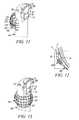
- FIG. 31is a perspective view of a thirteenth embodiment of the lead placement apparatus which allows removal of the lead in a transverse direction to the longitudinal axis of the apparatus.
- FIGS. 32A-32Bare end views of the embodiment shown in FIG. 31 showing closed and open positions, respectively.
- FIG. 33is a perspective view of a fourteenth embodiment of the lead placement apparatus which allows removal of the lead in a transverse direction to the longitudinal axis of the apparatus.
- FIG. 34is a sectional view along line 34 - 34 in FIG. 33 .
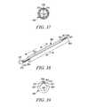
- FIG. 35is a longitudinal sectional view of a fifteenth embodiment of the lead placement apparatus which allows removal of the lead in a transverse direction to the longitudinal axis of the apparatus.
- FIG. 36is a side view of the embodiment shown in FIG. 35 showing removal of a longitudinally disposed portion of the apparatus.
- FIG. 37is a partial transverse sectional view of the embodiment shown in FIGS. 35-36 .
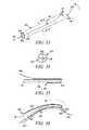
- FIG. 38is a perspective view of a sixteenth embodiment of the lead placement apparatus which allows removal of the lead in a transverse direction to the longitudinal axis of the apparatus.
- FIG. 39is a section view along line 39 - 39 of FIG. 38 .
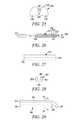
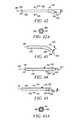
- FIG. 40is a side view of a seventeenth embodiment of the lead placement apparatus which allows removal of the lead in a transverse direction to the longitudinal axis of the apparatus.
- FIG. 40Ais a sectional view along line 40 A- 40 A of FIG. 40 .
- FIG. 41is a side view of the apparatus of FIG. 40 in an open position.
- FIG. 41Ais a sectional view of along line 41 A- 41 A of FIG. 41 .
- FIG. 42is a side view of an epicardial lead having an angled distal end portion.
- FIG. 42Ais a sectional view along line 42 A- 42 A of FIG. 42 .
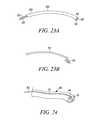
- FIG. 43is a side view of another epicardial lead having a curved distal end portion.
- FIGS. 44-45are side views of an epicardial lead having a distal end portion which is adapted to move between straight and angled positions, respectively.
- FIG. 45Ais a sectional view along line 45 A- 45 A of FIG. 45 .
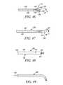
- FIGS. 46-47are side views of other epicardial leads having an angled distal end portion.
- FIG. 48is a side view of another epicardial lead having a distal end portion which is adapted to move between straight and angled positions.
- FIG. 49is a side view of an epicardial lead including a steering member.
- FIG. 50is a side view of an epicardial lead having an alternate distal section.
- FIG. 51is a side elevation view of a prior art epicardial lead placing the lead on a surface of the heart.
- FIG. 52is a side elevation view of the epicardial lead of the present invention placing the lead on a surface of the heart.
- FIG. 53a side view of a further embodiment of a lead placement apparatus of the present invention with portions of the apparatus shown in section.
- FIG. 54is a plan view of the lead placement apparatus of FIG. 53 .
- FIG. 55is a sectional view along line 55 - 55 of FIG. 53 .
- FIG. 56is an enlarged partial longitudinal sectional view of the lead placement apparatus of FIG. 53 with the distal end portion shown in a deflected configuration.
- FIG. 57is a side view of a still further embodiment of a lead placement apparatus having an expandible member with the distal end portion shown in section.
- FIG. 58is an enlarged partial longitudinal sectional view of the distal end portion of the lead placement apparatus in FIG. 57 .
- FIG. 59is a partial longitudinal sectional view of the lead placement apparatus in FIG. 57 showing the expandible member in an enlarged configuration.
- FIG. 60is a side view of the lead placement apparatus in FIG. 53 with portions of the apparatus shown in section showing insertion of a guiding or trocar device.
- FIG. 60Ais a cross sectional view along line 60 A- 60 A in FIG. 60 .
- FIG. 61is a side view of the lead placement apparatus, similar to FIG. 60 , showing insertion of a Doppler sensor.
- FIG. 62is a side view of the lead placement apparatus, similar to FIG. 60 , showing insertion of a lead.
- the present inventionprovides methods and apparatus for placing a lead on a surface of a human heart.
- a human heartmay also include the pericardium and the endocardial surface in addition to the epicardial surface.
- the manner in which the lead is placed on the heart surfacemay also vary.
- the leadmay be implanted or embedded into the surface using a retention member or fastener which penetrates beneath the surface. Different types of retention members may be utilized and it is not intended for the present invention to be limited only to those retention members shown in the drawings since it is realized that many variations may be used to effectuate lead retention without departing from the present invention.
- the leadmay be placed on the heart surface for either temporary or permanent use, as needed.
- a first embodiment of a lead placement apparatus 10 of the present inventionincludes an elongated body 12 and defines a longitudinal axis 13 .
- the body 12includes a proximal end portion generally at 14 and a distal end portion generally at 16 .
- the body 12defines a lead receiving passageway 18 which extends between a proximal inlet 20 and distal outlet 22 .
- the lead receiving passageway 18is adapted and suitable to receive a lead for attachment to the surface of the heart.
- the leadis shown, by way of example, in FIG. 16 which will be described below.
- a handle 24may be provided at the proximal end portion 14 of the body 12 .
- a preferred approachutilizes a sub-xyphoid approach to place the lead on a heart surface.
- Other approachesmay be utilized without departing from the scope of the claimed invention, such as, for example, intercostal, intravenous and other minimally invasive approaches as well as more invasive approaches, such as open chest procedures.
- the elongated body 12preferably has sufficient length so as to allow insertion of at least the distal end portion 16 of the body from a sub-xyphoid transcutaneous access opening to the area between the pericardium and the epicardial surface and into a space which is commonly referred to either as the pericardial space.
- the length of the bodywill depend on which medical approach is used to gain access to the heart surface. Importantly, the length of the body should be such that the handle 24 remains outside of the patient while the medical procedure is performed so as to allow greater control over the lead placement apparatus.
- the length L of the body 14 between the proximal inlet and the distal outlet 22has a length and a range of 10 cm to 40 cm, preferably 20 cm to 30 cm where a sub-xyphoid approach is used, so that the proximal inlet 20 is located outside of the patient.
- the proximal inlet 20is disposed at generally the proximal end portion 14 of the body 12 , although it is spaced from the proximal tip end of the handle.
- the length L of the body 12allows extension of the distal end portion 16 into the pericardial space while, at the same time, allowing the proximal inlet 20 to extend outside into the pericardial space and, preferably, outside of the incision access location into patient's body. In this way, the proximal inlet 20 is accessible to allow insertion of the lead therein. It is also possible to position the proximal inlet at other longitudinal positions along the body 12 as is indicated in FIG.
- the apparatus 26similarly has a length which is sized to allow insertion of the distal end portion 16 into the pericardial space and access to the handle 24 and proximal inlet 20 from the outside of the incision access location.
- the elongated body 12may have in certain, but not all embodiments of the present invention, a non-circular shape, so described because it has a cross-section which is non-circular as best seen in FIGS. 4 and 5 .
- the non-circular shapemay appear in a myriad of different forms, some of which will be shown and described below, but other non-circular shapes are also possible without departing from the present invention.
- the non-circular shapeis associated with at least a portion of the body, preferably, the portion of the body which is inserted into the pericardial space.
- the non-circular shapeextends along the body 12 between the proximal inlet 20 and the distal outlet 22 in FIG.
- the portion of the body 12 which contacts the heart surfacesuch as the distal end portion 16 has a non-circular shape.
- the non-circular shape of the body 12is generally constant along the body except near the distal end portion 16 where the body gradually tapers.
- the non-circular shapeincludes an upper surface 32 which is convex and a lower surface 34 which is planar. So the cross-sectional shape of the non-circular portion 30 in FIG. 4C has a “D” configuration. It is contemplated that the lower surface 34 faces the heart surface in which lead placement is desired and the upper surface 32 generally faces away from the desired lead placement site, although other orientations are also possible. As shown in FIGS. 3 and 4B the distal outlet 22 may be defined in the lower surface 34 near the distal end portion 16 of the body. So when the distal outlet 22 is placed adjacent the desire lead placement site, the lead can be advanced from the outlet opening in the lower surface 34 and directed at the heart tissue. It is realized that other locations of the distal outlet are possible without departing from the present invention.
- the portion of the body with the non-circular shapepreferably has a width, generally indicated at W, which is greater than its thickness, generally indicated at T.
- Wwidth
- Tthickness
- the width of the body 12is oriented in a generally parallel relationship to the heart surfaces.
- the lower surface 34is disposed adjacent the epicardial surface and at least a portion of the upper surface 32 is disposed adjacent the pericardium.
- the thickness of the body 12is oriented in a generally perpendicular relationship with the heart surfaces, so the non-circular shape of the body attributes a slim profile when inserted into the pericardial space.
- the working space existing within the pericardial spaceis more efficiently utilized, and displacement between the epicardial surface and pericardium is minimized when the body is inserted into the pericardial space. It can further be said that the non-circular shape of the body tends to retain the body at a selected angular orientation between the pericardium and the epicardial surface and prevents unplanned rotation of the body about its own axis. This assists in orienting the distal outlet in the desired direction so that it is pointed toward the heart surface.
- FIGS. 5A-5Eillustrate variations in the body 12 and like parts will be indicated with like numbers followed by a letter designation of A-E, as appropriate, which corresponds to the appropriate figure.
- FIGS. 5A and 5Bshow bodies, 12 A and 12 B, respectively, which are shaped similarly to the non-circular shaped body 12 in FIG. 4C , except that the internal arrangement of lumen is varied, as will be described later.
- FIG. 5Cillustrates an alternate non-circular shape of a body 12 C having an upper surface 32 C and a lower surface 34 C which are both convex so as to generally define an oval or eccentric shape.
- FIG. 5Dillustrates another alternate non-circular shape of the body 12 D having an upper surface 32 D which is convex and a lower surface 34 D which is concave.
- FIG. 5Eillustrates a body 12 E having an elongated oval shape where the upper and lower surfaces define substantially planar top and bottom portions which are joined by curved edge portions. The major axis of the oval is oriented along the width and the minor axis is oriented along the thickness.
- the upper surface 32will be in contact with the pericardium and the lower surface 34 which includes the distal outlet of the lead receiving passageway will generally be in contact with the epicardial surface.
- the non-circular portiongenerally has a width which is greater than its thickness and provides a relatively slim profile, insertion of the body into the pericardial space is facilitated.
- the distal outlet 22 of the lead receiving passageway 18is preferably located in the lower surface 34 , which faces the epicardial surface.
- the distal end portion 16 of the body 12 illustrated theregradually narrows from a more proximal portion of the body.
- the body 12narrows from the view shown in FIG. 4C to the successive view 4 B and then 4 A as the body extends to the distal end portion 16 .
- the bodymay retain a non-circular shape.
- FIGS. 4A and 4Balso generally retain the relative proportions of the body where the width which is greater than the thickness.
- FIGS. 3-4Balso illustrate a guide wire outlet 36 which is formed in the lower surface 34 of the body at the distal end portion 16 .
- the guide wire outlet 36is formed distally relative to the lead outlet or distal outlet 22 and, as shown in FIGS. 3 and 4 , the guide wire outlet 36 is in communication with the distal outlet 22 , and connects to the lead receiving passageway 18 .
- a guide wire 38is received by the lead receiving passageway 18 and is inserted from a more proximal portion of the body 12 , such as from either of the proximal inlets 20 and 28 in FIGS. 1 and 2 , respectively.
- the guide wire 38has a proximal end 40 and a distal end 42 which extends forwardly, or distally, through the guide wire outlet 36 .
- the guide wire outlet 36is generally defined as a channel extending longitudinally from the distal outlet 22 in the forward direction, similar to the entrance to an igloo.
- the guide wire outlet 36is sufficiently sized and oriented to allow passage of the guide wire but prevent passage of the lead.
- the guide wire outlet 36is sized smaller than the lead outlet and longitudinally oriented in order to avoid extension of the lead beyond the distal end portion 16 of the body.
- the distal end 42 of the guide wireextends forwardly of the distal end portion 16 so as to guide the apparatus 10 to the selected lead placement site.
- the guide wirealso may bisect the tissue so as to provide a clear working space for lead placement.
- the guide wiremay be removed from the body and successively thicker guide wires may be inserted.
- the lead receiving passageway 18may be sized so that it is adapted to receive the guide wire and the lead during use or, alternatively, the guide wire may be removed from passageway 18 prior to lead insertion. After proper placement of the distal end is confirmed, the lead may be inserted. When the distal tip of the lead engages the end of the body, the curved inner surface deflects the lead downwardly through the distal outlet 22 .
- FIGS. 4 and 4Calso illustrate steering members 52 disposed within the body 12 .
- the steering wires 52have a distal end 54 and a proximal end 56 .
- the distal end 54 of the steering membersis located at a position at or near the distal end portion 16 of the body and extends in a proximal direction towards the proximal end portion 14 of the body.
- the proximal end 56 of the steering membersmay extend from the proximal end portion 14 of the body 12 in a similar manner as described relative to the vacuum lumen 44 or it may extend to any of several intermediate positions of the body.
- the steering wires 52may be operatively connected to a steering collar 58 , as shown in FIGS. 1 and 2 , which is disposed at a more proximal portion of the body 12 adjacent the handle 24 and accessible to the doctor.
- the steering members 52are made of a suitable material having an elongated shape such as wire, fiber, filament, surgical tape or the like although other materials and forms are possible without departing from the present invention.
- the steering membermay include one or more separate members as shown in FIGS. 4 and 4C , which illustrates two steering members. By pulling on one member and pushing (or at least not pulling) the other, the distal end portion can be deflected in the desired direction. By reversing this action, the tip may be deflected in the opposite direction.
- the body 12and in particular, the handle 24 or steering collar 58 may include, various control elements such as levers, buttons, switches or the like to vary the application of force, the degree of curvature, and the direction of movement.
- the applied forcemay be tensile, compressive or rotational or any combination thereof.
- Tension and compressionmay be applied directly or indirectly to the steering member by pulling or pushing the steering member at any position along its length whereas rotation occurs by directly or indirectly twisting the steering member.
- the steering membersmay be used in combination with the vacuum lumen discussed above or, alternatively, in lieu of the vacuum lumen so as to orient the distal outlet in the desired direction for lead placement.
- the steering membersare each positioned on one side of the body and extend longitudinally relative to the body. So that within a first plane, tensile force applied to the proximal end 56 of the left steering member 52 in FIG. 4C will move the distal end portion 16 to the left. Similarly, tensile force applied to the proximal end of the right steering member in FIG. 4C will move the distal end portion to the right.
- FIGS. 5A and 5Billustrate alternate bodies 12 A and 12 B, respectively, each having a single steering member 52 A and 52 B, respectively.
- the steering member 52 Ais disposed in an upper left position.
- the steering member 52 Bis disposed in a lower right position. So, force applied either directly or indirectly to either steering member will cause deflection of the distal end portion 16 .
- a body 60includes a steering member 52 which extends through the body to the distal end portion 16 .
- the body 60generally defines a longitudinal axis 62 and at least the distal end portion 16 of the body is curved relative to the axis when normally positioned and not acted upon by any force.
- the bodymay be curved, for example, to an angle between 10 degrees and 80 degrees relative to the longitudinal axis 62 and preferably between approximately 30 and 60 degrees.
- the normal or at rest position of the bodyis illustrated in solid lines and dashed lines represent a position of the body after force has been applied either directly or indirectly to the steering member.
- the force, indicated at 64may be tensile, compressive or rotational or a combination thereof.
- the distal end portion 16moves to a less curved position as indicated by dashed lines.
- FIG. 22An alternate body 66 is illustrated in FIG. 22 , which likewise has a steering member 52 extending to the distal end portion 16 .
- the distal end portion 16is normally positioned in alignment with the longitudinal access 62 and force applied to the steering member 52 moves the distal end portion 16 of the body from the normally aligned straight position to a curved position relative to the longitudinal axis.
- any type of forcemay be used to move the distal end portion of the body in one or more planes so that the distal end portion of the body may be curved relative to the longitudinal axis in one or more planes in the range approximately of 10 degrees to 80 degrees.
- FIGS. 19 and 20show a least a portion of a body which is curved relative to a longitudinal axis 200 .
- a body 202 having a distal end portion 204is normally curved relative to the longitudinal axis 200 at the distal end portion.
- the bodyis made of a flexible or deformable material such as a polymer or plastic or may be made of a rigid material which is adapted to articulate.
- a distal outlet 206is defined in the distal end portion for extension of the lead therethrough.
- the body 202is slidably received in an elongated sleeve 208 .
- the sleeve 208has a rigid or semi-rigid, cylindrical shape and defines an inner lumen 210 which is sized sufficiently large to receive the body 202 for slidable movement.
- the sleeve diameteris slightly larger than the diameter of the body and preferably sized so as to fit snugly over the body and prevent incidental moving of the sleeve during insertion of the body into the pericardial space, although it is preferred that there be clearance between the proximal end of the sleeve and the proximal end of the body so as to permit axial movement of the sleeve on the body.
- the sleevepreferably has sufficient length so that during insertion of the sleeve and body into the pericardial space the sleeve extends from the distal end 206 of the body to a more proximal portion of the body which is located outside of the pericardial space for accessibility by the operator.
- the sleeve 208has a linear configuration so that when the sleeve is moved in a position where the sleeve 208 is positioned around the distal end 204 of the body, the body is temporarily deformed from its normally curved position to a straight configuration, which may be desired during introduction of the body initially into the patient's chest.
- the sleeve 208may be moved or retracted proximally relative to the distal end 204 so as to allow the portion of the body 202 which extends distally on the sleeve to resume its normally curved configuration, which may be at any angle between 10 degrees and 80 degrees relative to the longitudinal axis. Selective retraction of the sleeve may permit greater or lesser curvature of the body—depending on the length of the body that extends beyond the distal end of the sleeve.
- FIG. 20illustrates an alternative sleeve 212 having a curved portion relative to the longitudinal axis 200 .
- An inner bore 214sized to receive a body 216 .
- a distal end 218 of the sleeveis curved relative to the longitudinal axis 200 .
- the sleeve in FIG. 20maintains the body 216 in a curved orientation relative to the longitudinal axis where the body, instead of being normally curved, may be normally straight.
- the distal end of the bodywill maintain an orientation in the direction pointed by the distal end of the sleeve, or in other words, which is in coaxial alignment with the distal end 218 of the sleeve.
- the angle of curvature of the sleevemay be between 10 degrees and 80 degrees, for example.
- FIGS. 1-5Eillustrate a plurality of lumens or passageways defined by the body 12 and these lumens or passageways are adapted to receive or accommodate a myriad of elements. These lumens or passageways may have a variety of different orientations although they generally extend between a distal end or opening and a proximal end or opening.
- FIGS. 5A-5Eillustrate, in cross sectional views, various positions and combinations and orientations of the passageways within the lead placement apparatus, and are intended to be exemplary and not exclusive.
- the body 12defines a vacuum lumen 44 , which extends between a proximal opening 46 and a distal opening 48 .
- the proximal opening 46is located at the proximal end portion 14 of the body.
- FIG. 1illustrates the proximal opening 46 in the form of a rearwardly extending tube for attachment to a suction port of a vacuum source 50 .
- the distal opening 48 of the vacuum lumen 44is formed as an annulus or C-shaped configuration partially around the distal outlet 22 . This annulus provides a suction force at the distal outlet so as to help hold the distal outlet against the heart surface.
- FIGS. 5A-5CAlternate positions of the vacuum lumen 44 in the body are shown in FIGS. 5A-5C , as indicated by corresponding numbers 44 A- 44 C.
- FIGS. 5B-5Ebriefly illustrate other devices which may be introduced through the body and the associated lumen.
- the bodymay include passageways, such as a guide wire lumen 68 ( FIG. 5B ), a lumen for an elongated flexible or malleable element 70 ( FIG. 5C ), an inflation lumen 74 ( FIG. 5D ), an endoscope lumen 76 ( FIG. 5E ), a fluid delivery lumen 78 ( FIG. 5E ), and a lumen for a Doppler sensor 80 ( FIG. 5E ).
- a guide wire lumen 68FIG. 5B
- a lumen for an elongated flexible or malleable element 70FIG. 5C
- an inflation lumen 74FIG. 5D
- an endoscope lumen 76FIG. 5E
- a fluid delivery lumen 78FIG. 5E
- a Doppler sensor 80FIG. 5E
- FIG. 5Billustrates a dedicated guide wire lumen 68 which extends between a guide wire inlet and a guide wire outlet.
- the guide wire inletcan be located on a proximal portion of the body 12 B.
- the guide wire inletmay be positioned on the body as previously described relative to the proximal inlet 20 in FIGS. 1 and 2 .
- the guide wire outlet of the dedicated guide wire lumen 68is preferably disposed generally in proximity to the distal outlet 22 although the exact location may vary.
- the dedicated guide wire outletmay be positioned in the lower surface 34 adjacent the distal outlet or positioned, similar to the guide wire outlet 36 in FIGS. 3 and 4 (except that the guide wire would be dedicated or separate from the lead receiving passageway 18 ).
- Other locations for the dedicated guide wire outletare, of course, possible without departing from the present invention. Additional views of the dedicated guide wire lumen of the present invention are provided by FIGS. 15-17 in accordance with an alternate body design.
- a dedicated guide wire lumen 172is defined within the body 162 and receives a guide wire 190 so as to facilitate identification of a selected lead placement site. Use of the guide wire will be more particularly described relative to FIGS. 15-17 below.
- FIG. 5Cillustrates the flexible or malleable element 70 in cross section which will be described in conjunction with FIG. 24 .
- the flexible element 70includes a proximal end 82 and distal end 84 , which is generally coextensive with the distal end portion 16 of the body 86 .
- the element 70is disposed within the body and suitable for manual forming into a desired shape, such as a shape which corresponds to a surface of the heart so as facilitate placement of the body 22 adjacent a heart surface. Both the element and the body are sufficiently flexible so as to allow the surgeon to change the curvature of the body.
- the flexible element 70may be in the form of one or more malleable wires or other like shape-retaining material.
- the flexible elementhas been formed with several curvatures along it length and the distal end portion 16 is curved relative to the longitudinal axis 13 of the body.
- the flexible elementhas the added characteristic that it is malleable, and retains the desired shape once it is positioned. Retention of the desired shape is generally maintained until repositioned by the user. It is also possible that the shape could be retained by various locking mechanisms utilized on or within the body.
- FIG. 5Dshows the body 5 D of a lead placement apparatus which includes the inflation lumen 74 .
- the inflation lumengenerally extends between distal and proximal openings. This feature will be described further in relation to FIGS. 7-8 .
- each of the endoscope lumen 76 and the fluid delivery lumen 78similarly extend between distal and proximal openings.
- the endoscope lumenwill be described further in FIGS. 8-10 .
- Relative to the fluid delivery lumen 78it permits an introduction of fluid to the heart surface at the selected lead placement site.
- the fluid delivery lumenmay be connected in fluid communication with a fluid source at a proximal end of the lead placement apparatus.
- a distal opening of the fluid delivery lumen 78is preferably disposed adjacent the distal outlet.
- the body 12may further include at least one temporary pacing electrode 72 .
- the temporary pacing electrodeis shown in relation to a non-circular body, it is not intended to limit the temporary pacing electrode as such, and the temporary pacing electrode may be used in any of the illustrated body configurations or others not shown.
- one temporary pacing electrode 72is positioned proximally relative to the distal outlet 22 and another temporary pacing electrode 72 is positioned distally relative to the distal outlet at the distal end portion 16 of the body 12 .
- the distal temporary pacing electrodeflanks the guide wire outlet 36 .
- the temporary pacing electrodesare preferably disposed in proximity to the distal outlet 22 for contact with the surface of the heart when the body 12 is placed, for example, within the pericardial space, although other locations may also be suitable.
- a conductor 88extends from each temporary pacing electrode 72 to a more proximal portion of the body 12 .
- the conductors 88may extend to the proximal end portion 14 of the body for connection to an electrical pacing signal source, generally indicated at 90 in FIG. 1 .
- an electrical pacing signal sourcegenerally indicated at 90 in FIG. 1 .
- the conductorsare shown as positioned within the body, it is also possible that the conductors may extend outside at least a portion of the body.
- the temporary pacing electrodemay theoretically be adapted to pace the heart by contact with either one of the epicardial surface or the pericardium, although it is preferred that the temporary pacing electrode pace the heart by contact with the epicardial surface and the use of the temporary pacing electrodes will be described relative to contact with the epicardial surface.
- FIGS. 5A-5Eillustrate the conductors, corresponding to reference numerals 88 A- 88 E, respectively, extending through the body, as previously described.
- the conductorsgenerally extend parallel to the longitudinal axis of the body and, eventually, are connected to the pacing signal source. Variations are possible as to the location of the temporary pacing electrode along the body and within any of the various body shapes without departing from this aspect of the present invention. These alternate positions include but are not limited to the upper surface of the body.
- FIGS. 6A-6Cillustrate an alternate embodiment which includes a body, generally indicated at 92 , having an upper surface 91 and a lower surface 93 .
- a monopolar temporary pacing electrode 94is located at the lower surface 93 of the body 92 (and could be located in the upper surface if desired).
- the body 92also includes a vacuum lumen 95 , a lead receiving passageway 97 with a distal outlet 99 and a Doppler sensor 80 .
- the vacuum lumen 95has a distal opening 96 , which is rearwardly positioned relative to the distal outlet 22 .
- the monopolar temporary pacing electrode 94has a conductor 98 which extends along the body to a proximal portion of the body 92 .
- the monopolar temporary pacing electrode 94is located adjacent the distal outlet 22 so as to allow for pacing of the heart at a location closely adjacent to the outlet 99 to reflect the electrophysiological consequences of lead placement at that location prior to actual attachment of the lead. As discussed above in relation to FIG. 1 , the monopolar temporary pacing electrode is connected via the conductor 98 to a suitable pacing signal source typically outside the patient's body.
- FIGS. 23-23Banother variation of the temporary pacing electrode is shown in the form of a removable conductive probe.
- a body 100has a lead receiving passageway 102 extending between a distal end portion 103 and a proximal end portion 104 . At the distal end portion 103 , the lead receiving passageway 102 terminates in a distal outlet 105 .
- the lead receiving passageway 102 of the body 100may receive a removable elongated probe 106 having a proximal end 108 and a distal end 110 .
- Temporary pacing electrodes 112may be located on the distal end 110 of the elongated probe 106 .
- Conductors 113extend through the probe between the proximal and distal ends 108 and 110 for connection to a pacing signal source at the proximal end portion 104 of the body 100 .
- the elongated probe 106 with the temporary pacing electrodes 112is inserted into the proximal inlet of the lead receiving passageway 102 and extended along the passageway to the distal end portion 103 and through the distal outlet 105 .
- Contact between the conductive electrode(s) and the heart surfaceallows pacing of the heart.
- the probe 106may be removed from the passageway 102 so as to allow insertion of a lead 114 shown in FIG. 23B through the passageway 102 .
- the distal end 116 of the leadwill be attached to the selected lead placement site which was determined by the temporary pacing electrodes to be the suitable lead placement site.
- the temporary pacing electrodehas been particularly described and shown for used in connection with lead placement, it is contemplated that one or more temporary pacing electrodes may be used for a variety of other medical procedures including but limited to other procedures associated with the heart.
- the temporary pacing electrodemay be used to repeatedly temporarily pace the heart at a plurality of locations as necessary so as to map or analyze the conductive pathways of the heart tissue.
- the temporary pacing electrodemay be disposed on any of the previously described apparatus of the present invention or as a separate conductive probe as described above. Other variations and uses of the temporary pacing electrodes are also possible without departing from this aspect of the present invention.
- the Doppler sensor 80is preferably disposed adjacent to the distal outlet 99 for the purpose of identifying whether the lead placement outlet is too close to a coronary artery.
- a conductive element 118having a distal end 117 and a proximal end 119 is in communication with the Doppler sensor 80 at its distal end 117 .
- the conductive element 118extends to a more proximal portion of the body for communication with an operator-readable output device, which is shown generally at 120 in FIG. 7 .
- the Doppler element 80is positioned in the lower surface 93 of the body 92 adjacent the distal outlet 99 . When the distal end portion 16 of the body 92 is put into contact with a heart surface, use of the Doppler sensor allows for detection of a coronary artery in proximity to the distal outlet 99 .
- a Doppler sensor 80The structure and function of a Doppler sensor 80 is apparent to one skilled in the art and is described in U.S. Pat. No. 4,887,606 to Yock, et al., which is incorporated herein by reference. Variations in the positioning of the Doppler sensor are possible although positions adjacent the distal outlet 99 are preferred in order to more accurately determine the proximity of the coronary to the distal outlet before attachment of the lead. It is also possible to configure the Doppler sensor 80 at the end of a removable elongated probe, similar to the removable probe previously described relative to FIGS. 23-23B , so as to allow the Doppler sensor to be removably inserted into the lead receiving passageway prior to insertion of the lead.
- a body, generally indicated at 122is similar in some respects to the body of FIGS. 1-4C with like parts shown with like number.
- the body 122 of FIGS. 7 and 7Ais different in that it includes the inflation lumen 74 , previously described, and an expandible member 124 .
- the expandible member 124is shown as a balloon although other forms are also possible, some of which will be described below.
- the expandible member 124is disposed in proximity to the distal outlet 22 .
- the balloon 124is positioned on the upper surface 32 of the body opposite the distal outlet 22 .
- the balloonextends along the upper surface 32 of the body from the very end of the distal end portion 16 to a more proximal location along the body. It can be seen that the body, when it is inserted into a patient adjacent a cardiac surface and the balloon 124 is expanded by utilizing an inflation source, the balloon tends to bias the body 122 so that the lower surface 34 or distal outlet 22 is oriented and held adjacent the selected heart surface.
- the inflation lumen 74as shown in cross section in FIG.
- a proximal opening 126 of the inflation lumen 74is connected to an inflation source, indicated at 128 .
- the inflation sourceis typically filled with a fluid, preferably liquid, although a variety of liquids or gases may be used as will be apparent to one skilled in the art.
- FIG. 7Athe cross-sectional configuration of the body is shown as non-circular although the invention is not limited to a non-circular cross-sectional body shape and other shapes are also possible.
- the particular body shown in FIGS. 7 and 7Afurther includes temporary pacing electrodes connected to corresponding conductors 88 , a Doppler sensor 80 , and a vacuum lumen 44 to assist in positioning the body against the epicardial surface—although both an inflation device and a vacuum feature may not be required on the same device.
- FIGS. 8-9illustrate another variation of the balloon-type expandible member with like parts shown with like number.
- a body 130extending between a distal end portion 16 and a proximal end portion (not shown) includes an upper surface 32 and a lower surface 34 along its length.
- a distal outlet 22is located in the lower surface 34 and a portion of the lower surface adjacent the distal outlet 22 has a flattened shape.
- the expandible member 132is located along the upper surface 32 and is spaced slightly from the distal end portion 16 of the body, although it could be directly opposite the outlet 22 .
- FIG. 8illustrates the unexpanded position of the balloon in solid lines, and the expanded position of the balloon as dotted lines. In the unexpanded position the balloon rests substantially against the upper surface 32 of the body to provide a generally smooth body surface and a small body profile. In the expanded position, the balloon is spaced from the upper surface of the body.
- FIG. 9shows the expanded position of the balloon when the body 130 has been inserted into the pericardial space S.
- the body 130has sufficient length so as to allow insertion of the distal end portion into the pericardial space.
- the lower surface 34 of the body 130 in the vicinity of the distal outlet 22is oriented towards the epicardial surface E.
- the expandible member 132is inflated from its non-expanded to expanded position as fluid flows through the inflation lumen 74 and fills the balloon.
- the expanded balloonpushes against the pericardium P, thus biasing the lower surface 34 of the body 130 into contact with the epicardial surface E, the distal outlet 22 of the body being oriented in the desired direction for lead placement.
- the bodyfurther includes a dedicated guide wire lumen 68 , temporary pacing electrodes 72 , and the endoscope lumen 76 , all of which may be used to facilitate lead placement.
- the endoscope lumen 76extends through the body 130 .
- a distal opening 136 of the endoscope lumenis located adjacent the distal outlet 22 of the lead receiving passageway 18 .
- a proximal opening 137 of the endoscope lumenis disposed on a more proximal location of the body 130 .
- An endoscope or fiber optic viewing device 138which has a proximal and distal ends 140 and 142 is connected to a suitable output viewing device, such as a video monitor or the like and inserted into the proximal opening 137 of the endoscope lumen, by way of a suitable electrical or fiber optic connection.
- the distal end 142 of the endoscopeis advanced to the distal opening 136 and allows for viewing of the selected lead placement site.
- FIG. 10illustrates another body 144 which is similar to the body 130 of FIGS. 8 and 9 with like parts being shown with like number, except that a balloon-type expandible member 146 extends completely around the body.
- the expandible member 146is spaced a small distance from the distal outlet 22 and is circumferentially disposed on the body. As the expandible member 146 is inflated to its expanded position, shown in dotted lines in FIG. 10 , it expands outwardly relative to the body in a radial direction.
- FIGS. 11-12illustrate a body 148 which is similar to the one shown in FIG. 8 , with like parts being shown with like numbers, except the body in FIGS. 11-12 has another type of expandible member, generally indicated at 150 , which is comprised of a plurality of biasing members 152 which are longitudinally and laterally disposed relative to the body.
- the biasing members 152are disposed substantially aligned with the upper surface 32 in an unexpanded condition.
- the biasing members 152In an expanded position shown in FIGS. 11-12 , the biasing members 152 form a cage-like structure.
- the expanded biasing memberspush against the pericardium P in order to bias the lower surface 34 in the vicinity of the distal outlet 22 in contact with the epicardial surface E.
- the biasing membersare actuated to their expanded position using a spring, release wire, or other like methods.
- the biasing membersmay be normally biased to their expanded position and held in an unexpanded position during insertion by a suitable insertion sleeve, trocar or like device. Alternately, the biasing members may be moved to the expanded position using a mechanical linkage, pull wire or the like, which is actuated from a more proximal portion of the body 150 .
- FIG. 13illustrates an alternate body 154 similar to the one shown in FIGS. 11-12 except that an expandible member 156 is disposed circumferentially on the distal end portion of the body and spaced a small distance from the distal outlet 22 .
- the expandible memberis comprised of biasing members 157 which are longitudinally and laterally disposed relative to the longitudinal axis of the body.
- expandible membersare possible in addition to the expandible members shown in FIGS. 7-13 without departing from this aspect of the present invention including but not limited to an elastomeric membrane. Also, more than one expandible member may be positioned on the body, and if needed, and these may be positioned at different locations along the body.
- FIGS. 14-18illustrate the method of placing a lead on a heart surface.
- FIG. 14shows a patient's chest cavity, including a rib cage RC, a right lung RL, a left lung LL, a xyphoid XP, a heart HT, surrounded by a pericardium P, and percutaneous incision 158 .
- FIG. 14shows a lead placement apparatus, generally indicated at 160 , which includes a body, generally indicated at 162 .
- the body 162may have a non-circular shape, such as a convex upper surface 164 and a convex lower surface 166 , and defines a lead receiving passageway 168 terminating in a distal outlet 170 .
- the body 162may have a plurality of lumens or passageways to carry out a variety of functions during the lead placement procedure.
- these lumen or passagewaysmay include a guide wire lumen 172 terminating at a guide wire outlet 174 , temporary pacing electrodes 176 disposed adjacent the distal outlet 170 and connected by way of conductors 178 through the body to a pacing signal source, an endoscope lumen 180 , and a steering member 182 .
- the incision 158 through the patient's skinis made in the vicinity of the xyphoid XP. Then the guiding or trocar apparatus 160 is inserted through the percutaneous incision 158 to the pericardium P. Access to the pericardial space S as defined between the pericardium P and the epicardial surface E is made using an appropriate dilator device, indicated generally at 184 , which slices, punctures or otherwise gains access to the pericardial space through the pericardium.
- dilator deviceindicated generally at 184 , which slices, punctures or otherwise gains access to the pericardial space through the pericardium.
- the incision 158is approximately 3 mm to 5 mm in length and is made in the area of the xyphoid and the costal cartilage CC.
- a devicesuch as a needle, or the like, may then be advanced through the incision 158 toward the heart.
- a viewing devicemay be used to aid the advancement of the needle.
- Accesscan be made into the pericardium employing known techniques, which by way of example but not limitation these techniques can include a fluoroscopic contrast injection.
- a thin guide wire, indicated generally at 186such as, for example, a 0.018 inch thickness guide wire is then advanced under fluoroscopic guidance into the pericardial space.
- Successively thicker guide wirescan be inserted and removed sequentially into the pericardial space in order to sufficiently widen the incision for entry of the body 162 .
- the sizes of these guide wireswill vary. Examples of successively larger guide wires can range approximately between 0.018-0.05 inch and preferred sizes include 0.035 or 0.038 inch.
- An introduction sheath, or dilator, indicated generally at 188may be introduced over the guide wire into the pericardial space.
- FIGS. 14A-14Dsequentially illustrate the introduction of the needle 184 , the guide wire 186 , the dilator 188 , and insertion of the lead placement apparatus 160 through the dilator 188 .
- FIGS. 15 and 16illustrate insertion of the body 162 into the pericardial space S between the pericardium P and the epicardial surface E.
- the bodyis inserted into the pericardial space S a distance of approximately between 20 cm and 30 cm. If the body has a non-circular cross-sectional shape, such shape may extend along all or a portion of the body which is inserted into the pericardial space.
- the distal outlet 170is defined in the lower surface 166 of the body 162 so that when the body is inserted into the pericardial space the distal outlet 170 is oriented adjacent the epicardial surface E for lead placement.
- a guide wire 189 having a distal end 190 and a proximal end 191is inserted into the guide wire lumen 172 and extends forwardly of the guide wire outlet 174 .
- the guide wire 189may be used to assist in locating the desired lead placement site such as for example bisecting tissue to create a clear path for lead placement.
- the body 162is moved within the pericardial space until the distal outlet 170 is positioned at a selected lead placement site. Movement of the distal outlet 170 may be effectuated by the steering wire 182 where force is applied to the steering member at the proximal end portion of the body.
- An endoscope or other viewing devicemay be inserted into the endoscope lumen 180 so as to allow viewing of the epicardial surface as well as the selected lead placement site.
- the heartPrior to lead placement the heart is preferably paced utilizing at least one temporary pacing electrode 176 positioned adjacent the distal outlet 170 .
- Pacing of the heartis performed by placing the electrodes 176 in contact with the surface of the heart at a selected location so as to determine whether the selection location is suitable for lead placement. Electrical impulses are supplied to the heart through the temporary pacing electrodes and the effect of the such impulses are transmitted to external viewing devices so as to determine the optimal lead placement site.
- the temporary pacing electrodemay be used in connection with a variety of other diagnostic and/or therapeutic medical procedures such as, for example, for mapping and analyzing the conductive pathways of the heart.
- the temporary pacing electrodemay be inserted into the pericardial space either as part of any of the previously described apparatus or a separate pacing apparatus.
- the temporary pacing electrodemay be used repeatedly or sequentially at various locations so as to map and/or analyze the various conductive pathways of the patient's heart.
- FIG. 16illustrates a lead 192 having a distal end 194 and a more proximal end 196 .
- the leadis inserted into the lead receiving passageway 168 .
- the distal end 194 of the lead 192is advanced through the distal outlet 170 for attachment or engagement to the epicardial surface E.
- the lead 192engages either the epicardial surface E or the endocardial surface, located beneath the epicardial surface or both.
- the distal end 194 of the leadpreferably has an anchor that secures it to the heart surface.
- the anchormay take any of several well known forms, such as barb or a curved and pointed end which may be in the form of a screw or helix so as to facilitate attachment. Other shapes will be apparent so as to secure the lead to the heart and different shapes may be appropriate depending on the degree of lead permanence required.
- the steps of lead placementmay be repeated so as to engage a plurality of leads with a surface of the heart.
- FIG. 18shows the patient's chest after lead placement has occurred.
- the lead placement apparatusis withdrawn from the patient's chest.
- a portable pacer source 198may implanted into the subclavicular space, preferably the left subclavicular space, so as to provide an electrical pacing signal to the lead 192 by way of a connection between the proximal end 196 of the lead and the pacer source 198 .
- the methodhas been shown by way of example but not limitation using the above steps. It is realized however that other variations for performing the method of lead implantation are also possible and may be utilized in place of or in addition to the steps of the method already described. For example, the method may be performed utilizing a body having a vacuum lumen describe above relative to FIGS. 3-4C or FIGS. 6A-6C . A vacuum source provides suction to hold the distal outlet against the surface of the heart.
- the method of lead placement utilizing the temporary pacing electrodesis not limited to a body having a non-circular shape.
- a method of lead placementincludes providing a body having the Doppler sensor 80 , as shown and described relative to FIGS. 6A-6C , or a separate Doppler sensor. After the body is introduced into the pericardial space, the Doppler sensor is placed in contact with the epicardial surface at a selected location. As discussed relative to FIGS. 6A-6C , the Doppler sensor is located in the lower surface of the body although other positions are possible. Once in contact with the heart surface, the Doppler sensor is activated to detect whether the sensor or distal outlet 22 is in proximity to a coronary artery of the heart. The information is transmitted along the conductive element to the Doppler output device where it is read by the operator.
- the bodyis moved to another lead placement site. Successive detecting is performed so as to avoid placement of the lead in proximity to a coronary artery. If no coronary artery is detected unduly close to the distal outlet, the lead is advanced from the distal outlet and engaged with one or both of the epicardial and endocardial surfaces of the heart in a similar manner as shown in FIG. 16 . Thereafter, the lead placement apparatus may be withdrawn.
- the methodmay be performed where at least a portion of the body has a non-circular shape
- the method of lead placement which includes the Doppler sensoris not limited to a body having a non-circular shape.
- the expandible memberis deployed from an unexpanded position to an expanded position, such as by an inflation source or movement of biasing members.
- the expandible memberis carried by the body and disposed in the vicinity of the distal outlet so as to hold or bias the distal outlet against the selected lead placement site.
- the steering members, vacuum lumen and expandible memberany one or a combination thereof may be utilized so as to orient the distal outlet against a selected lead placement site.
- the method of lead placementfurther may include the introduction of a fluid to the heart surface, in which event the body has a fluid delivery lumen as described in relation to FIG. 5E .
- FIGS. 25-41Aare directed to a body construction and lead arrangement which facilitate removal of the lead from the lead placement apparatus and, in particular, in which the lead is removed from the lead placement apparatus in a direction which is transverse to the longitudinal axis of the body. Transverse lead removal as described below may be incorporated into any one or more previously described aspects of the invention.
- FIGS. 25 and 26illustrate a body 230 having a distal end portion 232 and a proximal end portion 234 .
- the bodyis shown having a non-circular shape in the transverse direction along at least a portion of the body, other shapes may also be employed.
- the bodyin FIG. 25 , includes a longitudinally extending seam or thin wall portion 236 , a lead receiving passageway 238 and passageways 240 .
- the thin wall portion 236is so called because it is thinner relative to the remaining portions of the body and it is adjacent to or forms a portion of the inner surface of the lead receiving passageway.
- the thin wall portion 236extends from a distal end portion 232 of the body to a more proximal portion of the body, and may extend to the proximal end portion 234 of the body or any intermediate body position.
- the thin wall portion 236preferably extends at least along the portion of the body which is inserted into the pericardial space of a patient.
- the length of the thin wall portion 236may range approximately between 10 cm and 40 cm, preferably 20 cm to 30 cm.
- a lead 240 having a distal end 244 and a more proximal end 246is shown inserted into the lead receiving passageway 232 during the lead placement procedure.
- the lead 242is removed from the body by separating the body along the thin wall portion 236 .
- the thin wall portionmay be thin enough or may even be perforated along its length so as to facilitate separation. Such separation may be initiated at the distal end portion 232 of the body or along a more proximal portion and then separation extends axially in an “unzipping” manner, from the initial separation site.
- FIG. 26shows separation of the thin wall portion extending from the distal end portion 232 and extending proximally to create a longitudinally disposed opening along the body. Thereafter, the lead 242 may be removed from the body in a transverse direction to longitudinal axis 250 of the body.
- the bodyis shown-having a plurality of passageways 240 which may incorporate any combination of features previously described to facilitate lead placement, these passageway are not intended to limit the present invention.
- FIGS. 27 and 28illustrate an alternative body, generally indicated at 252 , having a distal end portion 254 and a proximal end portion 256 and defining a longitudinally disposed channel, generally indicated at 258 , which extends in a proximal direction from the distal end portion 254 .
- the channelis approximately C-shaped or U-shaped, and has a bottom wall 257 and side walls 259 .
- the channelhas a top opening 261 to allow for lead removal.
- the channel 258is adapted to receive a lead which is removed through the top opening 261 in a direction which is transverse to the longitudinal direction of the body.
- the channel 258may extend along the entire length of the body or any portion of the body.
- the width of the top opening 261 in the channelis preferably smaller than the diameter of the lead 242 , to normally retain the lead within the channel.
- the bodyis preferably made of resilient polymeric material so that the side walls 259 flex outwardly to allow the top opening 261 to widen for removal of the lead.
- FIGS. 29 and 30illustrate lead removal in accordance with another aspect of the invention.
- a bodygenerally indicated at 260 , has a distal end portion 262 and a proximal end portion 264 and defines a channel 266 which is similar to the channel described in previous FIGS. 27 and 28 having a bottom wall, sides walls and an top opening except that the body 260 in FIGS. 29 and 30 includes an elongated C-shaped portion 268 which is received within the channel 266 .
- the C-shaped portion 268has a distal end 270 and a proximal end 272 and, when assembled with the channel, captures the lead between them.
- the C-shaped portion 268is located within the channel 266 , and has an outer convex surface 274 that cooperates with the inner concave surface of the channel 266 and is sized slightly smaller than the channel 266 so as to be received therein.
- the assembly of the C-shaped portion 268 and the channel 266defines a lead receiving passageway 278 for insertion of the lead.
- the body 260may have a non-circular shape in the transverse direction although other shapes are possible.
- a plurality of passageways 280also may be defined within the body and utilized to incorporate the features previously described.
- the C-shaped portion 268may be slidably or rotatably received within the channel 266 .
- the leadmay be released in two different ways. First, the C-shaped portion 268 may be rotated within channel 266 until the gaps or slots are aligned, allowing the lead to be removed from the body. Alternatively, the C-shaped portion 268 and channel 266 may be peeled apart, revealing the lead located therebetween.
- FIGS. 40-41Aemploy a similar arrangement, and generally illustrate rotational movement of a longitudinally disposed portion relative to the remainder of the body.
- a bodygenerally indicated at 282 , defines a lead receiving passageway 284 and has a circular shape in the transverse direction.
- the bodyis comprised of inner and outer longitudinally disposed portions 286 and 287 , respectively, which are concentrically positioned relative to one another and together define the lead receiving passageway 284 which receives a lead 288 .
- At least one of the longitudinally disposed portionsis rotated relative to the other.
- Each inner and outer portion 286 and 287has an opening 289 and 291 , respectively, which extends longitudinally along each portion.
- each openingmay vary in size and may vary relative to one another, the size of each opening is larger than the thickness of the lead so as to allow for lead removal transverse to the longitudinal axis of the body when the openings are aligned.
- the outer longitudinally disposed portion 287extends between a distal end portion 290 and a proximal end portion 292 and defines a longitudinal axis 294 .
- the inner longitudinally disposed portion 286is received within the lead receiving passageway 284 and extends between a distal end 296 and a proximal end 298 .
- at least one of the inner and outer portionsmay be curved at an acute angle relative to a longitudinal axis 294 of the body although other angles of curvature between 10 degrees and 80 degrees are possible.
- one of the inner and outer shaftmay be curved and the other may be straight in a similar manner as described relative to FIGS. 19-20 .
- the longitudinal position of inner and outer portions 286 and 297may be fixed relative to one another or capable of relatively slidable movement.
- FIGS. 40 and 40Aillustrate a first position of the body 282 where the openings 289 and 291 are circumferentially non-aligned relative to one another.
- the lead 288is inserted into the passageway 284 and a distal end 300 of the lead may be advanced past the distal ends 290 and 296 of both longitudinally-disposed portions. Removal of the lead may be achieved by rotating at least one of the inner and outer portions 286 and 287 relative to one another to a second or opened position, as shown in FIGS. 41 and 41A , in which the openings 289 and 291 are in circumferential alignment with one another.
- FIGS. 40A and 41Aillustrate rotational movement of the outer longitudinally disposed portion 287 relative to the inner longitudinally disposed portion 286 in the direction indicated by the arrow in FIG. 40A . Removal of the lead is illustrated by the arrow in FIG. 41 .
- FIGS. 31-32Bthey illustrate another lead placement apparatus having a body, generally indicated at 302 , which defines a longitudinal axis 304 and a lead receiving passageway 306 , and includes distal and proximal end portions 308 and 310 , respectively, and a longitudinally disposed seam indicated generally at 312 .
- the body 306is designed to separate along the longitudinally disposed seam 312 for lead removal in a transverse direction.
- the seam 312is defined by interlocking longitudinal edges of the body.
- One of the longitudinal edgesincludes a projection 314 and the other longitudinal end includes a recess 316 so that when the body defines a closed position as shown in FIG. 32A the projection 314 is seated within the recess 316 .
- the bodyis made of any suitable material or combination of materials which imparts flexibility characteristics. Examples of materials include, but are not limited to, polymeric material, common in medical devices.
- the materialmay have shape retention characteristics such as by thermoforming or the like, so that the body normally defines a closed position (as seen in FIG. 32A but without the need for interlocking features), but spreads apart easily as seen in FIG. 32B .
- a malleable metal stripmay be disposed within the body of FIG. 32A and surrounded by a non-metal material which maintains a normally closed position. Force applied to the metal strip may separate the projection 314 from the recess 316 .
- shape of the body 306is shown as circular, other shapes, such as the non-circular shapes described above, are also possible without departing from this aspect of the present invention.
- an alternate bodyindicated generally at 320 having distal and proximal end portions 322 and 324 , respectively, and including a seam indicated generally at 326 , which is similar to the body in FIGS. 31-32B , except that the seam is closed by overlapping longitudinal edges 328 and 330 , respectively, along of the body 320 .
- the seam 326is axially spaced from a longitudinal axis of the body 332 .
- a lead 338 received within the passageway 334may be removed in a transverse direction, by temporarily spreading the overlapping edges to form a longitudinal gap through which the lead maybe withdrawn as indicated in FIG. 33 .
- FIGS. 35-37illustrate a yet further embodiment of the lead placement apparatus which allows for removal of the lead in a transverse direction.
- a bodygenerally indicated at 340 , includes distal and proximal end portions 342 and 344 , respectively, and defines a lead receiving passageway 346 extending between the distal and proximal end portions for receiving a lead 348 .
- the bodyincludes a longitudinally disposed weakened portion 350 which is bounded between two thin walled portions or other lines of weakness 352 .
- a separate filament or wireis connected to the distal end of the weakened portion 350 , or an extension of the portion 350 extends in a proximal direction terminating at a tab 354 which is disposed in a more proximal portion of the body.
- removal of the lead 148 from the body 340may be achieved by pulling proximally on the tab 354 (or pulling on the wire or filament), as indicated by the arrow, causing separation along the thin walled portions 352 , thus opening the passageway 346 so as to allow removal of the lead in a transverse direction.
- an alternate bodyis shown similar to the body shown in FIGS. 35-37 , except that the body 360 includes a longitudinally disposed slide 362 which is slidably moveable relative to the remaining portion of the body in order to allow lead removal in a transverse direction.
- the body 360includes distal and proximal end portions 364 and 366 , respectively and defines a passageway 368 for receiving a lead.
- the bodymay have a circular or other shape and include a longitudinal opening between two longitudinally disposed edges 367 extending around the circumference of the body. The opening is defined along the body between the distal and proximal end portions 364 and 366 .
- Each longitudinal edge 367may include a projection 369 which also extends along the body and into side slots or recesses 373 of the slide member 362 .
- the opening defined between the longitudinal edges 369is unobstructed and permits lead removal in a direction which is transverse relative to the body.
- FIGS. 42 and 42Aillustrate an epicardial lead, generally indicated at 380 , which is comprised of an elongated outer sheath 382 and an inner member 384 .
- the outer sheath 382is made of an insulated material whereas the inner member is conductive.
- the sheath 382includes a distal end portion 386 and a proximal end portion 388 and defines a longitudinal axis 390 therebetween.
- the outer sheath 382is hollow and is preferably, but not exclusively, cylindrical in cross-sectional shape.
- a passageway 392is defined by an inner surface of the outer sheath 382 for receiving the inner member 384 .
- the distal end 386 of the sheath 382is fixed at an acute angle A relative to the longitudinal axis 390 .
- the angle Ais approximately 20 degrees relative to the longitudinal axis. It is realized that other acute angles may be utilized, such as between 10 degrees and 80 degrees, although the preferred range of the angle is between approximately 30 degrees to 60 degrees for directing a contact member toward the surface or the heart.
- the length of the angled portion of the sheath itselfmay measure approximately 10 mm to 20 mm.
- the inner member 384has a distal section 394 and a proximal section 396 .
- the inner member 384is elongated relative to the longitudinal axis 390 and generally defines a cylindrical cross-sectional shape.
- the inner member 384defines a contact anchor, which may be in the form of a nonlinear shape, preferably but not exclusively in the form of a helical or screw-like shape, so as to facilitate attachment of the inner member 384 to the epicardial surface of the heart.
- FIG. 42Ashows the inner member 384 as having a solid cylindrical cross-section, although other configurations and shapes are also possible without departing from the present invention.
- the inner memberis preferably made of a flexible or malleable material and comprises one or more conductive elements or wires which may be connected to a pacing signal source at the proximal section 396 .
- the sheath 382 and the inner member 384are capable of movement relative to one another so as to implant the inner conductive member on the epicardial surface of the heart.
- the inner member 384is moved so as to move the distal section 394 of the inner member distally of the distal end portion 386 of the outer sheath 382 .
- Any relative movementmay be utilized, such as rotational, translational or a combination thereof.
- the epicardial leadcan be configured to allow movement of the inner member in a direction which is transverse to the longitudinal axis 390 in accordance with previously described aspects of the invention.
- distal section 394 of the inner memberWhen lead implantation is desired, relative movement between the inner member and the outer sheath causes the distal section 394 of the inner member to be moved through the fixed angle A at the distal end portion 386 . As the distal section 394 passes through the distal end portion 386 , it assumes the angled position relative to the longitudinal axis 390 . Continued relative movement moves the distal section 394 beyond of the distal end portion 386 for contact with the heart of a patient and, in particular, the epicardial surface.
- the distal section 394allows for attachment of the inner member to the epicardial surface of the heart in any conventional manner, without the need for attachment from an orthogonal direction as found in prior art leads.
- the helical shape of the distal sectionmay be implanted or embedded into the epicardial surface of the heart by simple rotational movement of the inner conductive member.
- FIG. 52generally illustrates attachment of the inner member 384 of the epicardial lead 380 to the epicardial surface E of the heart where the distal section is disposed at an acute angle l, which ranges approximately between 10 degrees and 80 degrees, preferably between 30 degrees and 60 degrees.
- FIG. 51shows an epicardial lead, generally indicated at 398 , found within the prior art.
- the epicardial leadrequires the distal end to be disposed at a right angle R 1 so that the distal end is perpendicular to the epicardial surface and thus the epicardial lead forms a 90 degree bend relative to radius indicated at R 2 .
- FIG. 43illustrates an epicardial lead 400 similar to the one shown in FIGS. 42 and 42A , with like parts being shown with like number, except that an outer sheath 382 of the lead 400 has a distal end portion 386 which is fixed into a curved shape relative to the longitudinal axis.
- the angle, indicated at B, defined by the distal end portion 386is preferably in the range approximately between 10 degrees and 80 degrees, preferably 30 degrees and 60 degrees.
- the length of the curved portion of the sheathmeasures approximately 10 mm to 20 mm.
- FIGS. 44-45Aillustrate an epicardial lead, generally at 402 , which is comprised of an elongated, hollow outer insulated sheath 404 and an inner conductive member 406 .
- the sheath 404includes distal and proximal end portions 408 and 410 , respectively.
- the inner member 406includes distal and proximal sections 412 and 414 , respectively.
- the outer sheath 404defines a passageway 411 for receiving the inner member 406 and a longitudinal axis 416 . As previously described, the outer sheath 404 and the inner member 406 are movable relative to one another.
- the sheathAdjacent the distal end portion 408 of the outer sheath 404 , the sheath includes a collar 418 having a sloped proximal edge 419 . As shown in FIG. 44 , the proximal edge slopes downwardly in a distal direction to define a gap with the remaining portion of the sheath. Along an upper surface of the sheath, the proximal edge of the collar is pivotally connected at a hinge 420 to the remaining portion of the sheath 404 .
- the distal end portion 408 of the sheath 404is adapted to move between at least two positions.
- a first positionis illustrated in FIG. 44 .
- the distal end portion 408is positioned so that the passageway 411 for receiving the inner member 406 is in alignment with the longitudinal axis 416 .
- the sloped proximal edge 419is spaced from the remaining portion of the sheath.
- a second positionis illustrated in FIG. 45 where the distal end portion 408 is disposed at an angle, indicated at C, relative to the longitudinal axis 416 so that the passageway is disposed at the angle C relative to the longitudinal axis.
- Movement of the distal end portionis preferably controlled by a pre-set thermo-formed position of the distal end, or by a biasing member such as a spring or the like.
- the distal end portionis preferably biased such that the normal position of the spring results in the second position of the distal end portion shown in FIG. 45 .
- control structuresmay be carried at the proximal end portion 410 for controlling the angular position of the distal end portion.
- Other control membersmay be used to vary the angular orientation of the distal end portion 408 apart from the angular positions shown and described above without departing from this aspect of the present invention.
- an epicardial leadgenerally at 422 , includes an outer sheath 424 and an inner member 426 .
- a distal end portion 428 of the outer sheathcarries a sensor 430 such as, for example, a pacing electrode, Doppler sensor, fiber optic viewing device or endoscope which is connected to viewing means at a more proximal portion of the epicardial lead 422 .
- the distal end portion 428further defines a lumen 432 extending into the sheath in a proximal direction.
- the lumen 432is disposed at an acute angle relative to the longitudinal axis of the body and receives the sensor 430 therein.
- a spring or other biasing member 434is disposed within the lumen so as to normally bias the sensor 430 in an extended position, illustrated in FIG. 46 . Extension and retraction of the sensor may also be controlled at a more proximal portion of the epicardial lead.
- a distal section 436 of the inner member 426is preformed at an angle D relative to the longitudinal axis while the sheath 426 is aligned relative to a longitudinal axis 437 . So when the distal section 436 extends distally of the sheath 424 , the distal section will form the acute angle D relative to the longitudinal axis.
- the distal sectionis made of any suitable material which allows it to resume a normally curved position relative to the longitudinal axis of the lead.
- FIG. 47illustrates another epicardial lead, generally at 438 , having an outer sheath 440 and an inner member 442 .
- a distal end portion 444 of the sheath 440is curved at an acute angle, indicated at E, relative to the longitudinal axis 445 of the lead.
- the distal end portion 444includes a transverse opening 446 relative to the longitudinal axis 445 .
- a distal section 448 of the inner member 442is moved through the sheath 440 and extends through the transverse opening 446 .
- the transverse opening 446has a convex inner surface, so that when the distal section 448 of the inner member 442 is advanced, the distal section engages the convex inner surface of the opening 446 so as to be disposed at the angle E relative to the longitudinal axis.
- an epicardial leadgenerally at 450 , which generally includes an outer sheath 451 and an inner member 453 , includes a steering member 452 , such as a pull wire, having a distal end 454 and a proximal end 456 .
- the distal end 454 of the steering memberis connected in the vicinity of a distal end portion 458 of the sheath 451 . So the distal end portion 458 is moved upon application of force to the steering member at the proximal end 456 .
- Tensile compressive or rotational forcemay be applied to the steering members so as to move the distal end portion in a desired direction for lead placement.
- an alternate epicardial leadgenerally at 60 , utilizes a malleable elongated wire 462 which may be shaped to retain a desired angular orientation for lead placement.
- the wire 462is similar to that previously described in relation to FIG. 24 .
- Other featuresmay also be utilized to facilitate lead placement in accordance with previously discussed features.
- FIG. 50shows an epicardial lead 464 having a distal section, generally at 466 , with an alternate shape.
- the distal section 466has a nonlinear portion 468 as well as a linear portion 470 .
- the linear portionis distally located relative to the nonlinear portion and is used like a guide wire which may be used to dissect cardiac tissue and facilitate lead placement. Many other shapes and orientations are possible are possible without departing from this aspect of the present invention.
- FIGS. 53-62illustrate additional variations in the lead placement apparatus and method of the present invention.
- a lead placement apparatus generally indicated at 468includes an elongated body generally at 470 .
- the body 470defines a longitudinal axis and generally includes a proximal end portion 472 and a distal end portion 474 .
- the bodyis illustrated having a circular cross sectional shape although other shapes are also possible.
- a lead receiving passageway 476is defined within the body extending between a proximal inlet 478 and a distal outlet 480 .
- the passageway 476generally is shown as a centrally located lumen within the body although other positions are possible.
- One or more steering members 482are disposed within the body and are adapted to deflect the distal end portion 474 of the body from, for example, a straight configuration shown in FIG. 54 to a curved configuration shown in FIG. 56 , when force is applied to at least one of the steering members in the direction indicated by the arrow.
- the body 470also may include at least one temporary pacing electrode 484 and associated conductive element(s) 486 which connect to a pacing signal source at a distal end 488 , preferably outside of the patient's body.
- the bodyis suitably flexible so as to allow deflection of the distal end portion 474 upon application of force to the steering members.
- the bodyalso has sufficient stiffness so as to allow for rotational movement of the body during the lead placement procedure.
- the bodycan be rotated up to 360 degrees relative to its longitudinal axis. It is also possible that a portion of the body may be rotated relative to the remaining portion of the body, for example, the portion of the body extending into the pericardial space may be adapted for rotation up to 360 relative to the handle or proximal end portion 472 of the body. Because the tip is deflectable in at least one plane and the body has torsional rigidity that allows it to be rotated, the tip can, in effect, be deflected up to 360 degrees.
- FIGS. 57-59illustrate an alternate lead placement apparatus 490 which is similar to the apparatus 468 in FIGS. 53-56 , with like parts being shown with like number, except that the apparatus of FIGS. 57-59 includes an annular expandible member 492 , preferably a balloon type expandible member, which is carried by the body 470 .
- an inflation lumen 494is disposed within the body 470 and is in fluid communication with an inflation source generally at the proximal end portion 472 of the body.
- FIG. 59illustrates selective expansion of the balloon.
- a guiding or trocar device 496is illustrated and insertably received within the lead receiving passageway 476 .
- the lead receiving passagewayis suitably sized for temporarily receiving devices in addition to a lead during the lead placement procedure. These devices are preferably, but not necessarily, removed from the lead receiving passageway prior to insertion of the lead.
- a guide wire 498is insertably received within the trocar device 496 and can be advanced beyond the distal end portion 474 of the body 470 so as to help locate the selected lead placement site.
- a Doppler sensor 500is generally disposed in proximity to the distal outlet 480 and is connected through a conductor 501 to an operator readable output device 503 .
- the Doppler sensor 500may be configured as part of a sensing device which is inserted into the lead receiving passageway 476 and advanced through the body 470 to the distal outlet 480 for sensing the proximity of the distal outlet to a coronary artery.
- the Doppler sensorcan be mounted to the distal end portion 474 of the body in proximity to the distal outlet 480 .
- FIGS. 60-62also illustrate a method which utilizes the lead placement apparatus of FIGS. 53-56 .
- the trocar 496 and guide wire 498are inserted into the lead receiving passageway 476 and through the body 470 so as to facilitate introduction of the body into the pericardial space.
- a distal portion of the guide wire 498may extend beyond the distal end portion 474 of the body 470 .
- the guide wire 498may assist in piercing the pericardium or, alternatively, piercing of the pericardium may be performed separately by another appropriate instrument, for example, a needle or other like devices.
- the guide wire and/or the trocar 496may be inserted into the pericardial space to dilate the initial incision and widen the incision so as to allow insertion of the distal end portion 474 of the body 470 into the pericardial space.
- the guide wire and trocarare removed from the lead receiving passageway 476 and, if necessary, additional guide wires, dilators or other introduction sleeves of larger diameter may be inserted into the lead receiving passageway 476 so as to suitably widen the incision for introducing the body 470 into the pericardial space.
- the distal outlet 480may be oriented in the desired direction for lead placement using the steering members 482 . At least a portion of the body may also be rotated in 360 degrees.
- the temporary pacing electrodes 484may be placed in contact with successive locations of the epicardial surface of the heart for pacing of the heart.
- FIG. 61illustrates insertion of the Doppler sensor 500 into the lead receiving passageway 476 .
- the Doppler sensor 500 and its associated sensing deviceare inserted into the body to detect whether the selected lead placement site is in proximity to a coronary artery. If a coronary artery is detected, then the distal end portion is moved so as to avoid placement of the lead on a coronary artery. For example, the distal end portion 474 may be deflected using the steering members or it may be rotated, as necessary.
- the Doppler sensoris preferably removed prior to lead placement.
- a lead 504is inserted into the lead placement device 468 at the proximal inlet 478 and advanced to the distal outlet 480 .
- the leadis engaged with the selected lead placement site.
- a suitable retention membermay be disposed at the distal end of the lead for attachment to the epicardial or endocardial surface of the heart.
- the lead placement apparatusmay be utilized to perform the method in a similar manner as described relative to the lead placement apparatus of FIGS. 53-56 .
- the expandible membercan be enlarged after the distal end portion of the apparatus has been inserted into the pericardial space so as to enlarge the existing working and viewing space at the distal end portion of the body.
Landscapes
- Health & Medical Sciences (AREA)
- Heart & Thoracic Surgery (AREA)
- Cardiology (AREA)
- Engineering & Computer Science (AREA)
- Biomedical Technology (AREA)
- Nuclear Medicine, Radiotherapy & Molecular Imaging (AREA)
- Radiology & Medical Imaging (AREA)
- Life Sciences & Earth Sciences (AREA)
- Animal Behavior & Ethology (AREA)
- General Health & Medical Sciences (AREA)
- Public Health (AREA)
- Veterinary Medicine (AREA)
- Electrotherapy Devices (AREA)
- Surgical Instruments (AREA)
- Measurement Of The Respiration, Hearing Ability, Form, And Blood Characteristics Of Living Organisms (AREA)
Abstract
Description
Claims (18)
Priority Applications (2)
| Application Number | Priority Date | Filing Date | Title |
|---|---|---|---|
| US11/742,165US8996133B2 (en) | 2002-05-10 | 2007-04-30 | Methods and apparatus for lead placement on a surface of the heart |
| US13/271,908US9604053B2 (en) | 2002-05-10 | 2011-10-12 | Methods and apparatus for lead placement on a surface of the heart |
Applications Claiming Priority (2)
| Application Number | Priority Date | Filing Date | Title |
|---|---|---|---|
| US10/144,205US7610104B2 (en) | 2002-05-10 | 2002-05-10 | Methods and apparatus for lead placement on a surface of the heart |
| US11/742,165US8996133B2 (en) | 2002-05-10 | 2007-04-30 | Methods and apparatus for lead placement on a surface of the heart |
Related Parent Applications (1)
| Application Number | Title | Priority Date | Filing Date |
|---|---|---|---|
| US10/144,205DivisionUS7610104B2 (en) | 2002-05-10 | 2002-05-10 | Methods and apparatus for lead placement on a surface of the heart |
Related Child Applications (1)
| Application Number | Title | Priority Date | Filing Date |
|---|---|---|---|
| US13/271,908ContinuationUS9604053B2 (en) | 2002-05-10 | 2011-10-12 | Methods and apparatus for lead placement on a surface of the heart |
Publications (2)
| Publication Number | Publication Date |
|---|---|
| US20070203554A1 US20070203554A1 (en) | 2007-08-30 |
| US8996133B2true US8996133B2 (en) | 2015-03-31 |
Family
ID=29400281
Family Applications (5)
| Application Number | Title | Priority Date | Filing Date |
|---|---|---|---|
| US10/144,205Expired - LifetimeUS7610104B2 (en) | 2002-05-10 | 2002-05-10 | Methods and apparatus for lead placement on a surface of the heart |
| US11/687,334AbandonedUS20070156217A1 (en) | 2002-05-10 | 2007-03-16 | Apparatus for lead placement on a surface of the heart |
| US11/687,320AbandonedUS20070156220A1 (en) | 2002-05-10 | 2007-03-16 | Methods for lead placement on a surface of the heart |
| US11/742,165Expired - Fee RelatedUS8996133B2 (en) | 2002-05-10 | 2007-04-30 | Methods and apparatus for lead placement on a surface of the heart |
| US13/271,908Expired - Fee RelatedUS9604053B2 (en) | 2002-05-10 | 2011-10-12 | Methods and apparatus for lead placement on a surface of the heart |
Family Applications Before (3)
| Application Number | Title | Priority Date | Filing Date |
|---|---|---|---|
| US10/144,205Expired - LifetimeUS7610104B2 (en) | 2002-05-10 | 2002-05-10 | Methods and apparatus for lead placement on a surface of the heart |
| US11/687,334AbandonedUS20070156217A1 (en) | 2002-05-10 | 2007-03-16 | Apparatus for lead placement on a surface of the heart |
| US11/687,320AbandonedUS20070156220A1 (en) | 2002-05-10 | 2007-03-16 | Methods for lead placement on a surface of the heart |
Family Applications After (1)
| Application Number | Title | Priority Date | Filing Date |
|---|---|---|---|
| US13/271,908Expired - Fee RelatedUS9604053B2 (en) | 2002-05-10 | 2011-10-12 | Methods and apparatus for lead placement on a surface of the heart |
Country Status (3)
| Country | Link |
|---|---|
| US (5) | US7610104B2 (en) |
| AU (1) | AU2003272197A1 (en) |
| WO (1) | WO2004002288A2 (en) |
Cited By (8)
| Publication number | Priority date | Publication date | Assignee | Title |
|---|---|---|---|---|
| US9486281B2 (en) | 2010-04-13 | 2016-11-08 | Sentreheart, Inc. | Methods and devices for accessing and delivering devices to a heart |
| US9936956B2 (en) | 2015-03-24 | 2018-04-10 | Sentreheart, Inc. | Devices and methods for left atrial appendage closure |
| US10130369B2 (en) | 2015-03-24 | 2018-11-20 | Sentreheart, Inc. | Tissue ligation devices and methods therefor |
| US10258408B2 (en) | 2013-10-31 | 2019-04-16 | Sentreheart, Inc. | Devices and methods for left atrial appendage closure |
| US10631840B2 (en) | 2015-11-25 | 2020-04-28 | Talon Medical, LLC | Tissue engagement devices, systems, and methods |
| US10959752B2 (en) | 2014-02-28 | 2021-03-30 | Sentreheart Llc | Pericardial access devices and methods |
| US11224435B2 (en) | 2016-09-23 | 2022-01-18 | Sentreheart Llc | Devices and Methods for left atrial appendage closure |
| US11844526B2 (en) | 2018-03-27 | 2023-12-19 | Atricure, Inc. | Devices and methods for left atrial appendage closure |
Families Citing this family (198)
| Publication number | Priority date | Publication date | Assignee | Title |
|---|---|---|---|---|
| US6488689B1 (en) | 1999-05-20 | 2002-12-03 | Aaron V. Kaplan | Methods and apparatus for transpericardial left atrial appendage closure |
| US6505075B1 (en)* | 1999-05-29 | 2003-01-07 | Richard L. Weiner | Peripheral nerve stimulation method |
| US7398781B1 (en) | 1999-08-10 | 2008-07-15 | Maquet Cardiovascular, Llc | Method for subxiphoid endoscopic access |
| US7526342B2 (en) | 1999-08-10 | 2009-04-28 | Maquet Cardiovascular Llc | Apparatus for endoscopic cardiac mapping and lead placement |
| US7597698B2 (en) | 1999-08-10 | 2009-10-06 | Maquet Cardiovascular Llc | Apparatus and method for endoscopic encirclement of pulmonary veins for epicardial ablation |
| US7288096B2 (en)* | 2003-01-17 | 2007-10-30 | Origin Medsystems, Inc. | Apparatus for placement of cardiac defibrillator and pacer |
| US7264587B2 (en) | 1999-08-10 | 2007-09-04 | Origin Medsystems, Inc. | Endoscopic subxiphoid surgical procedures |
| US20050102003A1 (en)* | 2000-05-03 | 2005-05-12 | Grabek James R. | Perficardial pacing lead placement device and method |
| HK1056125A1 (en)* | 2000-07-15 | 2004-02-06 | Glaxo Group Limited | Medicament dispenser |
| US7146225B2 (en)* | 2002-10-30 | 2006-12-05 | Medtronic, Inc. | Methods and apparatus for accessing and stabilizing an area of the heart |
| DE10105592A1 (en) | 2001-02-06 | 2002-08-08 | Achim Goepferich | Placeholder for drug release in the frontal sinus |
| US20030160800A1 (en)* | 2002-02-22 | 2003-08-28 | Agfa-Gevaert | Multiscale gradation processing method |
| US7191015B2 (en)* | 2002-04-11 | 2007-03-13 | Medtronic Vascular, Inc. | Devices and methods for transluminal or transthoracic interstitial electrode placement |
| US7610104B2 (en) | 2002-05-10 | 2009-10-27 | Cerebral Vascular Applications, Inc. | Methods and apparatus for lead placement on a surface of the heart |
| US8956280B2 (en) | 2002-05-30 | 2015-02-17 | Intuitive Surgical Operations, Inc. | Apparatus and methods for placing leads using direct visualization |
| US8317816B2 (en) | 2002-09-30 | 2012-11-27 | Acclarent, Inc. | Balloon catheters and methods for treating paranasal sinuses |
| US20050080470A1 (en)* | 2003-10-09 | 2005-04-14 | Randy Westlund | Intramyocardial lead implantation system and method |
| US7846168B2 (en) | 2003-10-09 | 2010-12-07 | Sentreheart, Inc. | Apparatus and method for the ligation of tissue |
| US7369901B1 (en) | 2004-02-11 | 2008-05-06 | Pacesetter, Inc. | Myocardial lead and lead system |
| US7186214B2 (en)* | 2004-02-12 | 2007-03-06 | Medtronic, Inc. | Instruments and methods for accessing an anatomic space |
| US8932276B1 (en) | 2004-04-21 | 2015-01-13 | Acclarent, Inc. | Shapeable guide catheters and related methods |
| US7559925B2 (en) | 2006-09-15 | 2009-07-14 | Acclarent Inc. | Methods and devices for facilitating visualization in a surgical environment |
| US20190314620A1 (en) | 2004-04-21 | 2019-10-17 | Acclarent, Inc. | Apparatus and methods for dilating and modifying ostia of paranasal sinuses and other intranasal or paranasal structures |
| US9351750B2 (en) | 2004-04-21 | 2016-05-31 | Acclarent, Inc. | Devices and methods for treating maxillary sinus disease |
| US20070208252A1 (en) | 2004-04-21 | 2007-09-06 | Acclarent, Inc. | Systems and methods for performing image guided procedures within the ear, nose, throat and paranasal sinuses |
| US9399121B2 (en) | 2004-04-21 | 2016-07-26 | Acclarent, Inc. | Systems and methods for transnasal dilation of passageways in the ear, nose or throat |
| US10188413B1 (en) | 2004-04-21 | 2019-01-29 | Acclarent, Inc. | Deflectable guide catheters and related methods |
| US9089258B2 (en)* | 2004-04-21 | 2015-07-28 | Acclarent, Inc. | Endoscopic methods and devices for transnasal procedures |
| US7654997B2 (en) | 2004-04-21 | 2010-02-02 | Acclarent, Inc. | Devices, systems and methods for diagnosing and treating sinusitus and other disorders of the ears, nose and/or throat |
| US20060063973A1 (en) | 2004-04-21 | 2006-03-23 | Acclarent, Inc. | Methods and apparatus for treating disorders of the ear, nose and throat |
| US8747389B2 (en) | 2004-04-21 | 2014-06-10 | Acclarent, Inc. | Systems for treating disorders of the ear, nose and throat |
| US8864787B2 (en) | 2004-04-21 | 2014-10-21 | Acclarent, Inc. | Ethmoidotomy system and implantable spacer devices having therapeutic substance delivery capability for treatment of paranasal sinusitis |
| US8764729B2 (en) | 2004-04-21 | 2014-07-01 | Acclarent, Inc. | Frontal sinus spacer |
| US7803150B2 (en) | 2004-04-21 | 2010-09-28 | Acclarent, Inc. | Devices, systems and methods useable for treating sinusitis |
| US20060004323A1 (en) | 2004-04-21 | 2006-01-05 | Exploramed Nc1, Inc. | Apparatus and methods for dilating and modifying ostia of paranasal sinuses and other intranasal or paranasal structures |
| US9554691B2 (en) | 2004-04-21 | 2017-01-31 | Acclarent, Inc. | Endoscopic methods and devices for transnasal procedures |
| US7419497B2 (en) | 2004-04-21 | 2008-09-02 | Acclarent, Inc. | Methods for treating ethmoid disease |
| US8702626B1 (en) | 2004-04-21 | 2014-04-22 | Acclarent, Inc. | Guidewires for performing image guided procedures |
| US9101384B2 (en) | 2004-04-21 | 2015-08-11 | Acclarent, Inc. | Devices, systems and methods for diagnosing and treating sinusitis and other disorders of the ears, Nose and/or throat |
| US8894614B2 (en) | 2004-04-21 | 2014-11-25 | Acclarent, Inc. | Devices, systems and methods useable for treating frontal sinusitis |
| US7462175B2 (en) | 2004-04-21 | 2008-12-09 | Acclarent, Inc. | Devices, systems and methods for treating disorders of the ear, nose and throat |
| US20070167682A1 (en) | 2004-04-21 | 2007-07-19 | Acclarent, Inc. | Endoscopic methods and devices for transnasal procedures |
| US20060106442A1 (en)* | 2004-05-19 | 2006-05-18 | The Board Of Trustees Of The Leland Stanford Junior University | Devices and methods for treating cardiac pathologies |
| US7221982B2 (en)* | 2004-07-12 | 2007-05-22 | Cardiac Pacemakers, Inc. | Apparatus and method of coating implantable leads |
| US20060247750A1 (en)* | 2005-04-28 | 2006-11-02 | Seifert Kevin R | Guide catheters for accessing cardiac sites |
| US8951225B2 (en) | 2005-06-10 | 2015-02-10 | Acclarent, Inc. | Catheters with non-removable guide members useable for treatment of sinusitis |
| US20070010793A1 (en)* | 2005-06-23 | 2007-01-11 | Cardiac Pacemakers, Inc. | Method and system for accessing a pericardial space |
| US20080152165A1 (en)* | 2005-07-01 | 2008-06-26 | Luca Zacchi | Ad-hoc proximity multi-speaker entertainment |
| US7844348B2 (en)* | 2005-08-09 | 2010-11-30 | Greatbatch Ltd. | Fiber optic assisted medical lead |
| US8114113B2 (en) | 2005-09-23 | 2012-02-14 | Acclarent, Inc. | Multi-conduit balloon catheter |
| US7328071B1 (en) | 2005-10-12 | 2008-02-05 | Pacesetter, Inc. | Lead placement device |
| US8090451B2 (en)* | 2006-03-30 | 2012-01-03 | Medtronic Inc. | Transvenous active fixation lead system |
| US7899555B2 (en)* | 2006-04-11 | 2011-03-01 | Pacesetter, Inc. | Intrapericardial lead |
| US8244379B2 (en) | 2006-04-26 | 2012-08-14 | Medtronic, Inc. | Pericardium fixation concepts of epicardium pacing leads and tools |
| US7729783B2 (en)* | 2006-04-26 | 2010-06-01 | Medtronic, Inc. | Apparatus and methods for vacuum- and mechanically-assisted fixation of medical electrical leads |
| US20100217367A1 (en)* | 2006-06-23 | 2010-08-26 | Amir Belson | Transesophageal implantation of cardiac electrodes and delivery of cardiac therapies |
| US9023075B2 (en)* | 2006-06-30 | 2015-05-05 | Cvdevices, Llc | Devices, systems, and methods for lead delivery |
| US8036757B2 (en)* | 2006-09-10 | 2011-10-11 | Seth Worley | Pacing lead and method for pacing in the pericardial space |
| US9820688B2 (en) | 2006-09-15 | 2017-11-21 | Acclarent, Inc. | Sinus illumination lightwire device |
| US9993639B2 (en)* | 2006-10-31 | 2018-06-12 | Medtronic, Inc. | Implantable medical elongated member including a tissue receiving fixation cavity |
| US8012143B1 (en) | 2006-12-12 | 2011-09-06 | Pacesetter, Inc. | Intrapericardial delivery tools and methods |
| US8439687B1 (en) | 2006-12-29 | 2013-05-14 | Acclarent, Inc. | Apparatus and method for simulated insertion and positioning of guidewares and other interventional devices |
| SI2142107T1 (en) | 2007-03-30 | 2013-05-31 | Sentreheart, Inc. | Devices and systems for closing the left atrial appendage |
| JP5174891B2 (en)* | 2007-04-27 | 2013-04-03 | シーヴィ デヴァイシズ,エルエルシー | Devices, systems, and methods for accessing the epicardial surface of the heart |
| US8118757B2 (en) | 2007-04-30 | 2012-02-21 | Acclarent, Inc. | Methods and devices for ostium measurement |
| US8485199B2 (en) | 2007-05-08 | 2013-07-16 | Acclarent, Inc. | Methods and devices for protecting nasal turbinate during surgery |
| US7881810B1 (en) | 2007-05-24 | 2011-02-01 | Pacesetter, Inc. | Cardiac access methods and apparatus |
| DE102007032202B4 (en)* | 2007-07-11 | 2010-11-25 | Schölly Fiberoptic GmbH | endoscope |
| US8086324B1 (en) | 2007-09-27 | 2011-12-27 | Pacesetter, Inc. | Intrapericardial lead with distal region configured to optimize lead extraction |
| US10206821B2 (en) | 2007-12-20 | 2019-02-19 | Acclarent, Inc. | Eustachian tube dilation balloon with ventilation path |
| US8998892B2 (en)* | 2007-12-21 | 2015-04-07 | Atricure, Inc. | Ablation device with cooled electrodes and methods of use |
| US8182432B2 (en) | 2008-03-10 | 2012-05-22 | Acclarent, Inc. | Corewire design and construction for medical devices |
| US8874237B2 (en) | 2008-04-16 | 2014-10-28 | Medtronic, Inc. | Delivery catheter including side port and electrodes |
| RU2500337C2 (en) | 2008-07-30 | 2013-12-10 | Аккларент, Инк. | Device and methods of identifying orifice of paranasal sinus |
| BRPI0919195A2 (en)* | 2008-09-18 | 2019-09-24 | Acclarent Inc | Methods and Apparatus for the Treatment of Ear, Nose, and Throat Disorders |
| US20100076535A1 (en) | 2008-09-25 | 2010-03-25 | Boston Scientific Neuromodulation Corporation | Leads with non-circular-shaped distal ends for brain stimulation systems and methods of making and using |
| US9468364B2 (en) | 2008-11-14 | 2016-10-18 | Intuitive Surgical Operations, Inc. | Intravascular catheter with hood and image processing systems |
| US7978742B1 (en) | 2010-03-24 | 2011-07-12 | Corning Incorporated | Methods for operating diode lasers |
| US8435290B2 (en) | 2009-03-31 | 2013-05-07 | Acclarent, Inc. | System and method for treatment of non-ventilating middle ear by providing a gas pathway through the nasopharynx |
| AU2010232589B2 (en) | 2009-04-01 | 2014-11-27 | Atricure, Inc. | Tissue ligation devices and controls therefor |
| US8372055B2 (en)* | 2009-10-27 | 2013-02-12 | Medtronic, Inc. | Method of using a deflectable subselecting catheter |
| US8524302B2 (en) | 2009-11-02 | 2013-09-03 | Pepsico | Natural flavour enhancers and methods for making same |
| US8295944B2 (en) | 2009-11-30 | 2012-10-23 | Boston Scientific Neuromodulation Corporation | Electrode array with electrodes having cutout portions and methods of making the same |
| US8391985B2 (en) | 2009-11-30 | 2013-03-05 | Boston Scientific Neuromodulation Corporation | Electrode array having concentric windowed cylinder electrodes and methods of making the same |
| JP2011147758A (en)* | 2010-01-22 | 2011-08-04 | Olympus Corp | Treatment instrument |
| EP2528517B1 (en)* | 2010-01-27 | 2018-04-18 | Merit Medical Systems, Inc. | Shapeable retrieval device |
| US8346373B2 (en) | 2010-08-03 | 2013-01-01 | Medtronic, Inc. | Method and apparatus for delivering a lead to a heart |
| US9155492B2 (en) | 2010-09-24 | 2015-10-13 | Acclarent, Inc. | Sinus illumination lightwire device |
| US9872981B2 (en) | 2010-09-28 | 2018-01-23 | Biotrace Medical, Inc. | Device and method for positioning an electrode in a body cavity |
| JP2013537835A (en)* | 2010-09-28 | 2013-10-07 | ザ ボード オブ トラスティーズ オブ ザ リーランド スタンフォード ジュニア ユニバーシティ | Devices and methods for positioning electrodes in tissue |
| USD665076S1 (en)* | 2010-11-15 | 2012-08-07 | Karl Storz Gmbh & Co. Kg | Changing rod |
| ES2671928T3 (en) | 2011-06-08 | 2018-06-11 | Sentreheart, Inc. | Tissue ligation devices and tension devices for them |
| WO2013136312A2 (en)* | 2012-03-15 | 2013-09-19 | Krishnan Subramaniam Chitoor | Mechanism, system, method for in vivo lead fixation |
| US9883908B2 (en) | 2012-05-02 | 2018-02-06 | The Charlotte-Mecklenburg Hospital Authority | Devices, systems, and methods for treating cardiac arrhythmias |
| US9402531B2 (en)* | 2012-07-05 | 2016-08-02 | Pavilion Medical Innovations, Llc | Endoscopic cannulas and methods of using the same |
| BR112015019887A2 (en) | 2013-03-12 | 2017-07-18 | Sentreheart Inc | device for closing a target tissue |
| US9629684B2 (en) | 2013-03-15 | 2017-04-25 | Acclarent, Inc. | Apparatus and method for treatment of ethmoid sinusitis |
| US9433437B2 (en) | 2013-03-15 | 2016-09-06 | Acclarent, Inc. | Apparatus and method for treatment of ethmoid sinusitis |
| AU2014268717A1 (en) | 2013-05-24 | 2015-12-03 | Bioventrix, Inc. | Cardiac tissue penetrating devices, methods, and systems for treatment of congestive heart failure and other conditions |
| CA2922126A1 (en) | 2013-08-30 | 2015-03-05 | Bioventrix, Inc. | Cardiac tissue anchoring devices, methods, and systems for treatment of congestive heart failure and other conditions |
| US9242098B2 (en) | 2013-10-30 | 2016-01-26 | The Charlotte-Mecklenburg Hospital Authority | Devices, systems, and methods for treating cardiac arrhythmias |
| AU2015204693B2 (en) | 2014-01-10 | 2017-03-23 | Cardiac Pacemakers, Inc. | Methods and systems for improved communication between medical devices |
| WO2015106015A1 (en) | 2014-01-10 | 2015-07-16 | Cardiac Pacemakers, Inc. | Systems and methods for detecting cardiac arrhythmias |
| WO2015143327A1 (en) | 2014-03-21 | 2015-09-24 | Mayo Foundation For Medical Education And Research | Multi-electrode epicardial pacing |
| US9511219B1 (en)* | 2014-03-24 | 2016-12-06 | Subhajit Datta | Dual vacuum device for medical fixture placement including for thoracoscopic left ventricular lead placement |
| EP3139994B1 (en) | 2014-05-09 | 2024-05-22 | Merit Medical Systems, Inc. | Device for positioning an electrode in a body cavity |
| DE102014107087A1 (en)* | 2014-05-20 | 2015-11-26 | Bowa-Electronic Gmbh & Co. Kg | Sondenapplikator |
| CN107073275B (en) | 2014-08-28 | 2020-09-01 | 心脏起搏器股份公司 | Medical device with triggered blanking period |
| WO2016073509A1 (en)* | 2014-11-04 | 2016-05-12 | Cardiac Pacemakers, Inc. | Implantable medical devices and methods for making and delivering implantable medical devices |
| EP3253449B1 (en) | 2015-02-06 | 2018-12-12 | Cardiac Pacemakers, Inc. | Systems for safe delivery of electrical stimulation therapy |
| AU2016215606B2 (en) | 2015-02-06 | 2018-05-31 | Cardiac Pacemakers, Inc. | Systems and methods for treating cardiac arrhythmias |
| US10046167B2 (en) | 2015-02-09 | 2018-08-14 | Cardiac Pacemakers, Inc. | Implantable medical device with radiopaque ID tag |
| CN107530002B (en) | 2015-03-04 | 2021-04-30 | 心脏起搏器股份公司 | System and method for treating cardiac arrhythmias |
| US10050700B2 (en) | 2015-03-18 | 2018-08-14 | Cardiac Pacemakers, Inc. | Communications in a medical device system with temporal optimization |
| EP3270768B1 (en) | 2015-03-18 | 2023-12-13 | Cardiac Pacemakers, Inc. | Communications in a medical device system with link quality assessment |
| US10195421B2 (en) | 2015-08-12 | 2019-02-05 | Medtronic, Inc. | Epicardial defibrilation lead with side helix fixation and placement thereof |
| CN108136186B (en) | 2015-08-20 | 2021-09-17 | 心脏起搏器股份公司 | System and method for communication between medical devices |
| CN108136187B (en) | 2015-08-20 | 2021-06-29 | 心脏起搏器股份公司 | System and method for communication between medical devices |
| US9968787B2 (en) | 2015-08-27 | 2018-05-15 | Cardiac Pacemakers, Inc. | Spatial configuration of a motion sensor in an implantable medical device |
| US9956414B2 (en) | 2015-08-27 | 2018-05-01 | Cardiac Pacemakers, Inc. | Temporal configuration of a motion sensor in an implantable medical device |
| US10137305B2 (en) | 2015-08-28 | 2018-11-27 | Cardiac Pacemakers, Inc. | Systems and methods for behaviorally responsive signal detection and therapy delivery |
| WO2017040115A1 (en) | 2015-08-28 | 2017-03-09 | Cardiac Pacemakers, Inc. | System for detecting tamponade |
| US10226631B2 (en) | 2015-08-28 | 2019-03-12 | Cardiac Pacemakers, Inc. | Systems and methods for infarct detection |
| WO2017044389A1 (en) | 2015-09-11 | 2017-03-16 | Cardiac Pacemakers, Inc. | Arrhythmia detection and confirmation |
| WO2017062806A1 (en) | 2015-10-08 | 2017-04-13 | Cardiac Pacemakers, Inc. | Devices and methods for adjusting pacing rates in an implantable medical device |
| EP3389775B1 (en) | 2015-12-17 | 2019-09-25 | Cardiac Pacemakers, Inc. | Conducted communication in a medical device system |
| US10905886B2 (en) | 2015-12-28 | 2021-02-02 | Cardiac Pacemakers, Inc. | Implantable medical device for deployment across the atrioventricular septum |
| WO2017127548A1 (en) | 2016-01-19 | 2017-07-27 | Cardiac Pacemakers, Inc. | Devices for wirelessly recharging a rechargeable battery of an implantable medical device |
| CN109069840B (en) | 2016-02-04 | 2022-03-15 | 心脏起搏器股份公司 | Delivery system with force sensor for leadless cardiac devices |
| EP4331509A3 (en) | 2016-02-26 | 2024-05-15 | AtriCure, Inc. | Devices for left atrial appendage closure |
| EP3892324B1 (en) | 2016-03-18 | 2023-05-24 | Teleflex Life Sciences Limited | Pacing guidewire |
| EP3436142B1 (en) | 2016-03-31 | 2025-04-30 | Cardiac Pacemakers, Inc. | Implantable medical device with rechargeable battery |
| US10328272B2 (en) | 2016-05-10 | 2019-06-25 | Cardiac Pacemakers, Inc. | Retrievability for implantable medical devices |
| US10668294B2 (en) | 2016-05-10 | 2020-06-02 | Cardiac Pacemakers, Inc. | Leadless cardiac pacemaker configured for over the wire delivery |
| EP3474945B1 (en) | 2016-06-27 | 2022-12-28 | Cardiac Pacemakers, Inc. | Cardiac therapy system using subcutaneously sensed p-waves for resynchronization pacing management |
| US11207527B2 (en) | 2016-07-06 | 2021-12-28 | Cardiac Pacemakers, Inc. | Method and system for determining an atrial contraction timing fiducial in a leadless cardiac pacemaker system |
| WO2018009392A1 (en) | 2016-07-07 | 2018-01-11 | Cardiac Pacemakers, Inc. | Leadless pacemaker using pressure measurements for pacing capture verification |
| EP3487579B1 (en) | 2016-07-20 | 2020-11-25 | Cardiac Pacemakers, Inc. | System for utilizing an atrial contraction timing fiducial in a leadless cardiac pacemaker system |
| WO2018035343A1 (en) | 2016-08-19 | 2018-02-22 | Cardiac Pacemakers, Inc. | Trans septal implantable medical device |
| EP3503970B1 (en) | 2016-08-24 | 2023-01-04 | Cardiac Pacemakers, Inc. | Cardiac resynchronization using fusion promotion for timing management |
| EP3503799B1 (en) | 2016-08-24 | 2021-06-30 | Cardiac Pacemakers, Inc. | Integrated multi-device cardiac resynchronization therapy using p-wave to pace timing |
| US10994145B2 (en) | 2016-09-21 | 2021-05-04 | Cardiac Pacemakers, Inc. | Implantable cardiac monitor |
| US10758737B2 (en) | 2016-09-21 | 2020-09-01 | Cardiac Pacemakers, Inc. | Using sensor data from an intracardially implanted medical device to influence operation of an extracardially implantable cardioverter |
| CN109803720B (en) | 2016-09-21 | 2023-08-15 | 心脏起搏器股份公司 | Leadless stimulation device having a housing containing its internal components and functioning as a terminal for a battery case and an internal battery |
| US10238865B2 (en) | 2016-10-06 | 2019-03-26 | Medtronic, Inc. | Electrode fixation in interventional medical systems |
| WO2018081275A1 (en) | 2016-10-27 | 2018-05-03 | Cardiac Pacemakers, Inc. | Multi-device cardiac resynchronization therapy with timing enhancements |
| US10328257B2 (en) | 2016-10-27 | 2019-06-25 | Medtronic, Inc. | Electrode fixation in interventional medical systems |
| CN109922860B (en) | 2016-10-27 | 2023-07-04 | 心脏起搏器股份公司 | Implantable medical device delivery system with integrated sensor |
| US10561330B2 (en) | 2016-10-27 | 2020-02-18 | Cardiac Pacemakers, Inc. | Implantable medical device having a sense channel with performance adjustment |
| US10434314B2 (en) | 2016-10-27 | 2019-10-08 | Cardiac Pacemakers, Inc. | Use of a separate device in managing the pace pulse energy of a cardiac pacemaker |
| US10413733B2 (en) | 2016-10-27 | 2019-09-17 | Cardiac Pacemakers, Inc. | Implantable medical device with gyroscope |
| EP3532161B1 (en) | 2016-10-27 | 2023-08-30 | Cardiac Pacemakers, Inc. | Implantable medical device with pressure sensor |
| EP3532157B1 (en) | 2016-10-31 | 2020-08-26 | Cardiac Pacemakers, Inc. | Systems for activity level pacing |
| US10434317B2 (en) | 2016-10-31 | 2019-10-08 | Cardiac Pacemakers, Inc. | Systems and methods for activity level pacing |
| WO2018089311A1 (en) | 2016-11-08 | 2018-05-17 | Cardiac Pacemakers, Inc | Implantable medical device for atrial deployment |
| WO2018089308A1 (en) | 2016-11-09 | 2018-05-17 | Cardiac Pacemakers, Inc. | Systems, devices, and methods for setting cardiac pacing pulse parameters for a cardiac pacing device |
| US10881869B2 (en) | 2016-11-21 | 2021-01-05 | Cardiac Pacemakers, Inc. | Wireless re-charge of an implantable medical device |
| WO2018093605A1 (en) | 2016-11-21 | 2018-05-24 | Cardiac Pacemakers, Inc. | Leadless cardiac pacemaker providing cardiac resynchronization therapy |
| US11147979B2 (en) | 2016-11-21 | 2021-10-19 | Cardiac Pacemakers, Inc. | Implantable medical device with a magnetically permeable housing and an inductive coil disposed about the housing |
| US10639486B2 (en) | 2016-11-21 | 2020-05-05 | Cardiac Pacemakers, Inc. | Implantable medical device with recharge coil |
| CN109963618B (en) | 2016-11-21 | 2023-07-04 | 心脏起搏器股份公司 | Leadless cardiac pacemaker with multi-mode communication |
| US11207532B2 (en) | 2017-01-04 | 2021-12-28 | Cardiac Pacemakers, Inc. | Dynamic sensing updates using postural input in a multiple device cardiac rhythm management system |
| CN110198759B (en) | 2017-01-26 | 2023-08-11 | 心脏起搏器股份公司 | Leadless implantable device with removable fasteners |
| US10029107B1 (en) | 2017-01-26 | 2018-07-24 | Cardiac Pacemakers, Inc. | Leadless device with overmolded components |
| JP7000438B2 (en) | 2017-01-26 | 2022-01-19 | カーディアック ペースメイカーズ, インコーポレイテッド | Human device communication with redundant message transmission |
| CN110740779B (en) | 2017-04-03 | 2024-03-08 | 心脏起搏器股份公司 | Cardiac pacemaker with pacing pulse energy modulation based on sensed heart rate |
| US10905872B2 (en) | 2017-04-03 | 2021-02-02 | Cardiac Pacemakers, Inc. | Implantable medical device with a movable electrode biased toward an extended position |
| US11267481B2 (en) | 2017-07-14 | 2022-03-08 | Ccc Intelligent Solutions Inc. | Driver assist design analysis system |
| US10730526B2 (en) | 2017-07-14 | 2020-08-04 | Ccc Information Services Inc. | Driver assist design analysis system |
| US10918875B2 (en) | 2017-08-18 | 2021-02-16 | Cardiac Pacemakers, Inc. | Implantable medical device with a flux concentrator and a receiving coil disposed about the flux concentrator |
| CN111032148B (en) | 2017-08-18 | 2024-04-02 | 心脏起搏器股份公司 | Implantable medical device with pressure sensor |
| US11865334B2 (en)* | 2017-08-21 | 2024-01-09 | MRM MedTech, LLC | Lead with integrated feature including a low friction component to facilitate extraction and associated methods of extraction |
| US10933247B2 (en)* | 2017-08-21 | 2021-03-02 | MRM MedTech, LLC | Lead with integrated features to facilitate extraction and associated methods of extraction |
| US11235163B2 (en) | 2017-09-20 | 2022-02-01 | Cardiac Pacemakers, Inc. | Implantable medical device with multiple modes of operation |
| US10750936B2 (en)* | 2017-11-02 | 2020-08-25 | Olympus Corporation | Pericardial-cavity observing method |
| US11185703B2 (en) | 2017-11-07 | 2021-11-30 | Cardiac Pacemakers, Inc. | Leadless cardiac pacemaker for bundle of his pacing |
| EP3717059B1 (en) | 2017-12-01 | 2024-11-20 | Cardiac Pacemakers, Inc. | Systems for detecting atrial contraction timing fiducials within a search window from a ventricularly implanted leadless cardiac pacemaker |
| CN111417433B (en) | 2017-12-01 | 2024-04-30 | 心脏起搏器股份公司 | Method and system for detecting atrial contraction timing reference during ventricular filling from a ventricularly implanted leadless cardiac pacemaker |
| WO2019108830A1 (en) | 2017-12-01 | 2019-06-06 | Cardiac Pacemakers, Inc. | Leadless cardiac pacemaker with reversionary behavior |
| WO2019108482A1 (en) | 2017-12-01 | 2019-06-06 | Cardiac Pacemakers, Inc. | Methods and systems for detecting atrial contraction timing fiducials and determining a cardiac interval from a ventricularly implanted leadless cardiac pacemaker |
| US11529523B2 (en) | 2018-01-04 | 2022-12-20 | Cardiac Pacemakers, Inc. | Handheld bridge device for providing a communication bridge between an implanted medical device and a smartphone |
| WO2019136148A1 (en) | 2018-01-04 | 2019-07-11 | Cardiac Pacemakers, Inc. | Dual chamber pacing without beat-to-beat communication |
| CN111886046B (en) | 2018-03-23 | 2025-05-27 | 美敦力公司 | AV-synchronized VFA cardiac therapy |
| JP2021518192A (en) | 2018-03-23 | 2021-08-02 | メドトロニック,インコーポレイテッド | VfA cardiac resynchronization therapy |
| EP3768160B1 (en) | 2018-03-23 | 2023-06-07 | Medtronic, Inc. | Vfa cardiac therapy for tachycardia |
| US11235161B2 (en) | 2018-09-26 | 2022-02-01 | Medtronic, Inc. | Capture in ventricle-from-atrium cardiac therapy |
| US11951313B2 (en) | 2018-11-17 | 2024-04-09 | Medtronic, Inc. | VFA delivery systems and methods |
| US12296177B2 (en) | 2018-12-21 | 2025-05-13 | Medtronic, Inc. | Delivery systems and methods for left ventricular pacing |
| US11679265B2 (en) | 2019-02-14 | 2023-06-20 | Medtronic, Inc. | Lead-in-lead systems and methods for cardiac therapy |
| US11272956B2 (en) | 2019-03-17 | 2022-03-15 | Ripple, LLC | Systems and methods for implanting electrode leads |
| US11697025B2 (en) | 2019-03-29 | 2023-07-11 | Medtronic, Inc. | Cardiac conduction system capture |
| US11213676B2 (en) | 2019-04-01 | 2022-01-04 | Medtronic, Inc. | Delivery systems for VfA cardiac therapy |
| US11712188B2 (en) | 2019-05-07 | 2023-08-01 | Medtronic, Inc. | Posterior left bundle branch engagement |
| US11305127B2 (en) | 2019-08-26 | 2022-04-19 | Medtronic Inc. | VfA delivery and implant region detection |
| US11813466B2 (en) | 2020-01-27 | 2023-11-14 | Medtronic, Inc. | Atrioventricular nodal stimulation |
| US11911168B2 (en) | 2020-04-03 | 2024-02-27 | Medtronic, Inc. | Cardiac conduction system therapy benefit determination |
| US11813464B2 (en) | 2020-07-31 | 2023-11-14 | Medtronic, Inc. | Cardiac conduction system evaluation |
| US20250152917A1 (en)* | 2023-11-14 | 2025-05-15 | Neuravi Limited | Catheter with enhanced navigability to avoid ophthalmic artery |
Citations (102)
| Publication number | Priority date | Publication date | Assignee | Title |
|---|---|---|---|---|
| US3496932A (en) | 1967-12-22 | 1970-02-24 | Gen Motors Corp | Method and apparatus for substernal cardiac massage |
| US3703169A (en) | 1969-12-27 | 1972-11-21 | Olympus Optical Co | Endoscope |
| US3896793A (en) | 1973-06-19 | 1975-07-29 | Olympus Optical Co | Endoscope with view field altering means |
| US4030509A (en) | 1975-09-30 | 1977-06-21 | Mieczyslaw Mirowski | Implantable electrodes for accomplishing ventricular defibrillation and pacing and method of electrode implantation and utilization |
| US4181123A (en) | 1977-12-28 | 1980-01-01 | The University Of Virginia Alumni Patents Foundation | Apparatus for cardiac surgery and treatment of cardiovascular disease |
| US4257278A (en) | 1979-08-24 | 1981-03-24 | General Electric Company | Quantitative volume blood flow measurement by an ultrasound imaging system featuring a Doppler modality |
| US4280510A (en) | 1979-02-08 | 1981-07-28 | Medtronic, Inc. | Sutureless myocardial lead introducer |
| US4319562A (en) | 1977-12-28 | 1982-03-16 | The University Of Virginia Alumni Patents Foundation | Method and apparatus for permanent epicardial pacing or drainage of pericardial fluid and pericardial biopsy |
| US4424818A (en) | 1982-02-18 | 1984-01-10 | Medtronic, Inc. | Electrical lead and insertion tool |
| US4662377A (en) | 1985-11-07 | 1987-05-05 | Mieczyslaw Mirowski | Cardioverting method and apparatus utilizing catheter and patch electrodes |
| US4706655A (en) | 1986-08-26 | 1987-11-17 | Welch Allyn, Inc. | Shield for endoscope elevator cable seal |
| US4759348A (en) | 1981-09-28 | 1988-07-26 | Cawood Charles David | Endoscope assembly and surgical instrument for use therewith |
| US4765341A (en) | 1981-06-22 | 1988-08-23 | Mieczyslaw Mirowski | Cardiac electrode with attachment fin |
| US4817608A (en) | 1987-05-29 | 1989-04-04 | Mieczyslaw Mirowski | Cardioverting transvenous catheter/patch electrode system and method for its use |
| US4841949A (en) | 1986-12-10 | 1989-06-27 | Olympus Optical Co., Ltd. | Endoscope with a device for raising a medical instrument |
| US4887606A (en) | 1986-09-18 | 1989-12-19 | Yock Paul G | Apparatus for use in cannulation of blood vessels |
| US4944753A (en) | 1988-09-26 | 1990-07-31 | Burgess Frank M | Method for producing retro-sternal space |
| US4991578A (en) | 1989-04-04 | 1991-02-12 | Siemens-Pacesetter, Inc. | Method and system for implanting self-anchoring epicardial defibrillation electrodes |
| US4991603A (en) | 1989-10-30 | 1991-02-12 | Siemens-Pacesetter, Inc. | Transvenously placed defibrillation leads via an inferior vena cava access site and method of use |
| US4998975A (en) | 1989-10-30 | 1991-03-12 | Siemens-Pacesetter, Inc. | Travenously placed defibrillation leads |
| US5033477A (en) | 1987-11-13 | 1991-07-23 | Thomas J. Fogarty | Method and apparatus for providing intrapericardial access and inserting intrapericardial electrodes |
| US5106580A (en) | 1991-02-14 | 1992-04-21 | Metal Samples Company, Inc. | Probe insertion and retraction tool |
| US5213570A (en) | 1990-12-14 | 1993-05-25 | Mallinckrodt Medical, Inc. | System and method for oxygenation of the pericardium |
| US5243977A (en) | 1991-06-26 | 1993-09-14 | Trabucco Hector O | Pacemaker |
| US5269326A (en) | 1991-10-24 | 1993-12-14 | Georgetown University | Method for transvenously accessing the pericardial space via the right auricle for medical procedures |
| US5306234A (en) | 1993-03-23 | 1994-04-26 | Johnson W Dudley | Method for closing an atrial appendage |
| US5336252A (en) | 1992-06-22 | 1994-08-09 | Cohen Donald M | System and method for implanting cardiac electrical leads |
| US5336231A (en) | 1992-05-01 | 1994-08-09 | Adair Edwin Lloyd | Parallel channel fixation, repair and ligation suture device |
| US5385156A (en) | 1993-08-27 | 1995-01-31 | Rose Health Care Systems | Diagnostic and treatment method for cardiac rupture and apparatus for performing the same |
| US5423821A (en) | 1994-01-18 | 1995-06-13 | Pasque; Michael K. | Sternal closure device |
| US5433730A (en) | 1989-05-03 | 1995-07-18 | Intermedics, Inc. | Conductive pouch electrode for defibrillation |
| US5498228A (en) | 1994-08-08 | 1996-03-12 | John W. Royalty | Electromagnetic bi-ventricular assist device |
| US5520701A (en) | 1993-06-16 | 1996-05-28 | Lerch; Karl-Dieter | Set for the treatment of vascular deformations |
| US5582580A (en) | 1992-07-30 | 1996-12-10 | Temple University - Of The Commonwealth System Of Higher Education | Direct manual cardiac compression device |
| US5634895A (en) | 1994-06-23 | 1997-06-03 | Cormedics Corp. | Apparatus and method for transpericardial delivery of fluid |
| US5676162A (en) | 1992-08-06 | 1997-10-14 | Electric Boat Corporation | Reciprocating pump and linear motor arrangement |
| US5678547A (en) | 1988-12-22 | 1997-10-21 | Biofield Corp. | Method and apparatus for screening or sensing bodily conditions using DC biopotentials |
| US5683445A (en) | 1996-04-29 | 1997-11-04 | Swoyer; John M. | Medical electrical lead |
| US5682906A (en) | 1993-02-22 | 1997-11-04 | Heartport, Inc. | Methods of performing intracardiac procedures on an arrested heart |
| US5707336A (en) | 1995-01-09 | 1998-01-13 | Cardassist Incorporated | Ventricular assist device |
| US5716392A (en) | 1996-01-05 | 1998-02-10 | Medtronic, Inc. | Minimally invasive medical electrical lead |
| WO1998005289A1 (en) | 1996-08-01 | 1998-02-12 | Fogarty Thomas J | Minimally invasive direct cardiac massage device and method |
| US5725521A (en) | 1996-03-29 | 1998-03-10 | Eclipse Surgical Technologies, Inc. | Depth stop apparatus and method for laser-assisted transmyocardial revascularization and other surgical applications |
| US5752526A (en) | 1996-02-19 | 1998-05-19 | The Cleveland Clinic Foundation | Minimally invasive cardiac surgery procedure |
| US5766189A (en) | 1996-02-29 | 1998-06-16 | Olympus Optical Co., Ltd. | Clip device |
| US5797946A (en) | 1995-07-13 | 1998-08-25 | Origin Medsystems, Inc. | Method for arterial harvest and anastomosis for coronary bypass grafting |
| US5797870A (en) | 1995-06-07 | 1998-08-25 | Indiana University Foundation | Pericardial delivery of therapeutic and diagnostic agents |
| US5799661A (en) | 1993-02-22 | 1998-09-01 | Heartport, Inc. | Devices and methods for port-access multivessel coronary artery bypass surgery |
| US5800414A (en) | 1996-10-18 | 1998-09-01 | Synthelabo | Catheter with flexible and elongate body |
| US5823955A (en)* | 1995-11-20 | 1998-10-20 | Medtronic Cardiorhythm | Atrioventricular valve tissue ablation catheter and method |
| US5823946A (en) | 1994-07-22 | 1998-10-20 | Origin Medsystems, Inc. | Method for creating a mediastinal working space |
| US5827216A (en) | 1995-06-07 | 1998-10-27 | Cormedics Corp. | Method and apparatus for accessing the pericardial space |
| US5840059A (en) | 1995-06-07 | 1998-11-24 | Cardiogenesis Corporation | Therapeutic and diagnostic agent delivery |
| US5865791A (en) | 1995-06-07 | 1999-02-02 | E.P. Technologies Inc. | Atrial appendage stasis reduction procedure and devices |
| US5871531A (en) | 1997-09-25 | 1999-02-16 | Medtronic, Inc. | Medical electrical lead having tapered spiral fixation |
| US5882299A (en) | 1997-01-31 | 1999-03-16 | Minnesota Scientific, Inc. | Device and procedure for minimally invasive coronary anastomosis |
| US5895298A (en) | 1997-05-29 | 1999-04-20 | Biofield Corp. | DC biopotential electrode connector and connector condition sensor |
| US5897586A (en) | 1997-08-15 | 1999-04-27 | Regents Of The University Of Minnesota | Implantable defibrillator lead |
| US5900433A (en) | 1995-06-23 | 1999-05-04 | Cormedics Corp. | Vascular treatment method and apparatus |
| US5910124A (en) | 1994-01-10 | 1999-06-08 | Cardiassist Incorporated | Ventricular assist device and method |
| US5931787A (en) | 1997-02-11 | 1999-08-03 | Tetrad Corporation | Sheath and methods of ultrasonic guidance for biopsy and catheter insertion |
| USRE36269E (en) | 1993-01-21 | 1999-08-17 | Minnesota Mining And Manufacturing Company | Saw blade retention system |
| US5947953A (en) | 1997-08-06 | 1999-09-07 | Hemocleanse, Inc. | Splittable multiple catheter assembly and methods of inserting the same |
| US5961440A (en) | 1997-01-02 | 1999-10-05 | Myocor, Inc. | Heart wall tension reduction apparatus and method |
| US5964699A (en) | 1998-01-23 | 1999-10-12 | Rultract, Inc. | Surgical support apparatus with a Z-shape rake plate |
| US5968010A (en) | 1997-04-30 | 1999-10-19 | Beth Israel Deaconess Medical Center, Inc. | Method for transvenously accessing the pericardial space via the right atrium |
| US5984866A (en) | 1998-01-23 | 1999-11-16 | Rultract, Inc. | Surgical support apparatus with splined coupling, cross bar support and head-to-toe extension for surgical retractor apparatus |
| US5991668A (en) | 1997-09-25 | 1999-11-23 | Medtronic, Inc. | Medical electrical lead |
| US6006122A (en) | 1997-09-25 | 1999-12-21 | Medtronic, Inc. | Medical electrical lead |
| US6015382A (en) | 1997-10-16 | 2000-01-18 | General Surgical Innovations, Inc. | Inflatable manipulator for organ positioning during surgery and method of use |
| US6081738A (en) | 1998-01-15 | 2000-06-27 | Lumend, Inc. | Method and apparatus for the guided bypass of coronary occlusions |
| US6083153A (en) | 1998-01-23 | 2000-07-04 | Rultract, Inc. | Xiphoid retraction system and method of performing reoperative midsternotomy |
| US6090042A (en) | 1998-01-23 | 2000-07-18 | Rullo; Janice Lee | Surgical support apparatus with adjustable rake and adjustable cable lifting disk |
| US6095968A (en) | 1998-04-10 | 2000-08-01 | Cardio Technologies, Inc. | Reinforcement device |
| US6110170A (en) | 1996-03-20 | 2000-08-29 | Cardiothoracic Systems, Inc. | Surgical instrument for facilitating the detachment of an artery and the like |
| US6120431A (en) | 1997-03-14 | 2000-09-19 | Allegheny-Singer Research Institute | Method for assisting stystolic and diastolic cardiac function |
| US6148230A (en) | 1998-01-30 | 2000-11-14 | Uab Research Foundation | Method for the monitoring and treatment of spontaneous cardiac arrhythmias |
| US6149595A (en) | 1998-07-02 | 2000-11-21 | Seitz; Walter S. | Noninvasive apparatus and method for the determination of cardiac valve function |
| US6155968A (en) | 1998-07-23 | 2000-12-05 | Wilk; Peter J. | Method and device for improving cardiac function |
| US6167889B1 (en) | 1995-04-10 | 2001-01-02 | Cardiothoracic Systems, Inc. | Method for coronary artery bypass |
| US6199556B1 (en) | 1998-05-01 | 2001-03-13 | Cardiothoracic Systems, Inc. | Xyphoid access for cardiac surgical procedures |
| US6200303B1 (en) | 1997-04-30 | 2001-03-13 | Beth Israel Deaconess Medical Center, Inc. | Method and kit for transvenously accessing the pericardial space via the right atrium |
| US6206004B1 (en) | 1996-12-06 | 2001-03-27 | Comedicus Incorporated | Treatment method via the pericardial space |
| US6221007B1 (en) | 1996-05-03 | 2001-04-24 | Philip S. Green | System and method for endoscopic imaging and endosurgery |
| US6224584B1 (en) | 1997-01-14 | 2001-05-01 | Eclipse Surgical Technologies, Inc. | Therapeutic and diagnostic agent delivery |
| US6237605B1 (en) | 1996-10-22 | 2001-05-29 | Epicor, Inc. | Methods of epicardial ablation |
| US6258021B1 (en) | 1993-06-17 | 2001-07-10 | Peter J. Wilk | Intrapericardial assist method |
| US6266550B1 (en) | 1998-01-16 | 2001-07-24 | Lumend, Inc. | Catheter apparatus for treating arterial occlusions |
| US6283127B1 (en) | 1992-12-03 | 2001-09-04 | Wesley D. Sterman | Devices and methods for intracardiac procedures |
| US6293906B1 (en) | 2000-01-14 | 2001-09-25 | Acorn Cardiovascular, Inc. | Delivery of cardiac constraint jacket |
| US6296630B1 (en) | 1998-04-08 | 2001-10-02 | Biocardia, Inc. | Device and method to slow or stop the heart temporarily |
| US6312404B1 (en) | 1996-09-13 | 2001-11-06 | Boston Scientific Corporation | Single operator exchange billiary catheter |
| US6311692B1 (en) | 1996-10-22 | 2001-11-06 | Epicor, Inc. | Apparatus and method for diagnosis and therapy of electrophysiological disease |
| US6311693B1 (en) | 1993-02-22 | 2001-11-06 | Wesley D. Sterman | Method and systems for performing thoracoscopic cardiac bypass and other procedures |
| US6319201B1 (en) | 1997-10-15 | 2001-11-20 | Peter J. Wilk | Imaging device and associated method |
| US6333347B1 (en) | 1999-01-29 | 2001-12-25 | Angiotech Pharmaceuticals & Advanced Research Tech | Intrapericardial delivery of anti-microtubule agents |
| US6352503B1 (en) | 1998-07-17 | 2002-03-05 | Olympus Optical Co., Ltd. | Endoscopic surgery apparatus |
| US20020087208A1 (en)* | 1997-12-03 | 2002-07-04 | Scimed Life Systems, Inc. | Devices and methods for creating lesions in endocardial and surrounding tissue to isolate focal arrhythmia substrates |
| US6423051B1 (en) | 1999-09-16 | 2002-07-23 | Aaron V. Kaplan | Methods and apparatus for pericardial access |
| US20020099390A1 (en) | 1999-05-20 | 2002-07-25 | Kaplan Aaron V. | Methods and apparatus for transpericardial left atrial appendage closure |
| US20030212446A1 (en) | 2002-05-10 | 2003-11-13 | Kaplan Aaron V. | Methods and apparatus for lead placement on a surface of the heart |
| US7004173B2 (en) | 2000-12-05 | 2006-02-28 | Lumend, Inc. | Catheter system for vascular re-entry from a sub-intimal space |
Family Cites Families (10)
| Publication number | Priority date | Publication date | Assignee | Title |
|---|---|---|---|---|
| US431562A (en)* | 1890-07-08 | Tag-holder | ||
| US5385938B1 (en)* | 1986-12-23 | 1997-07-15 | Tristrata Inc | Method of using glycolic acid for treating wrinkles |
| CA2118886C (en)* | 1993-05-07 | 1998-12-08 | Dennis Vigil | Method and apparatus for dilatation of a stenotic vessel |
| GB9504870D0 (en)* | 1995-03-10 | 1995-04-26 | Sandoz Ltd | Improvements in or relating to organic compounds |
| CA2242356C (en)* | 1996-01-08 | 2005-08-23 | Biosense, Inc. | Methods and apparatus for myocardial revascularization |
| US5792946A (en)* | 1996-04-02 | 1998-08-11 | Chastonay; Herman A. | Pendulum length balancing of golf clubs including graphite shafted golf clubs |
| US5965699A (en)* | 1996-11-06 | 1999-10-12 | The United States Of America As Represented By The Secretary Of The Army | Assay for the proteolytic activity of serotype a from clostridium botulinum |
| US6158317A (en)* | 1998-10-15 | 2000-12-12 | Uniloy Milacron Inc. | Post molding inner diameter neck trimming apparatus |
| US6224574B1 (en)* | 1999-10-18 | 2001-05-01 | Hassan Al-Labban | Combined scalpel and syringe device |
| US6531410B2 (en)* | 2001-02-27 | 2003-03-11 | International Business Machines Corporation | Intrinsic dual gate oxide MOSFET using a damascene gate process |
- 2002
- 2002-05-10USUS10/144,205patent/US7610104B2/ennot_activeExpired - Lifetime
- 2003
- 2003-05-09WOPCT/US2003/014435patent/WO2004002288A2/ennot_activeApplication Discontinuation
- 2003-05-09AUAU2003272197Apatent/AU2003272197A1/ennot_activeAbandoned
- 2007
- 2007-03-16USUS11/687,334patent/US20070156217A1/ennot_activeAbandoned
- 2007-03-16USUS11/687,320patent/US20070156220A1/ennot_activeAbandoned
- 2007-04-30USUS11/742,165patent/US8996133B2/ennot_activeExpired - Fee Related
- 2011
- 2011-10-12USUS13/271,908patent/US9604053B2/ennot_activeExpired - Fee Related
Patent Citations (126)
| Publication number | Priority date | Publication date | Assignee | Title |
|---|---|---|---|---|
| US3496932A (en) | 1967-12-22 | 1970-02-24 | Gen Motors Corp | Method and apparatus for substernal cardiac massage |
| US3703169A (en) | 1969-12-27 | 1972-11-21 | Olympus Optical Co | Endoscope |
| US3896793A (en) | 1973-06-19 | 1975-07-29 | Olympus Optical Co | Endoscope with view field altering means |
| US4030509A (en) | 1975-09-30 | 1977-06-21 | Mieczyslaw Mirowski | Implantable electrodes for accomplishing ventricular defibrillation and pacing and method of electrode implantation and utilization |
| US4319562A (en) | 1977-12-28 | 1982-03-16 | The University Of Virginia Alumni Patents Foundation | Method and apparatus for permanent epicardial pacing or drainage of pericardial fluid and pericardial biopsy |
| US4181123A (en) | 1977-12-28 | 1980-01-01 | The University Of Virginia Alumni Patents Foundation | Apparatus for cardiac surgery and treatment of cardiovascular disease |
| US4280510A (en) | 1979-02-08 | 1981-07-28 | Medtronic, Inc. | Sutureless myocardial lead introducer |
| US4257278A (en) | 1979-08-24 | 1981-03-24 | General Electric Company | Quantitative volume blood flow measurement by an ultrasound imaging system featuring a Doppler modality |
| US4765341A (en) | 1981-06-22 | 1988-08-23 | Mieczyslaw Mirowski | Cardiac electrode with attachment fin |
| US4759348A (en) | 1981-09-28 | 1988-07-26 | Cawood Charles David | Endoscope assembly and surgical instrument for use therewith |
| US4424818A (en) | 1982-02-18 | 1984-01-10 | Medtronic, Inc. | Electrical lead and insertion tool |
| US4662377A (en) | 1985-11-07 | 1987-05-05 | Mieczyslaw Mirowski | Cardioverting method and apparatus utilizing catheter and patch electrodes |
| US4706655A (en) | 1986-08-26 | 1987-11-17 | Welch Allyn, Inc. | Shield for endoscope elevator cable seal |
| US4887606A (en) | 1986-09-18 | 1989-12-19 | Yock Paul G | Apparatus for use in cannulation of blood vessels |
| US4841949A (en) | 1986-12-10 | 1989-06-27 | Olympus Optical Co., Ltd. | Endoscope with a device for raising a medical instrument |
| US4817608A (en) | 1987-05-29 | 1989-04-04 | Mieczyslaw Mirowski | Cardioverting transvenous catheter/patch electrode system and method for its use |
| US5033477A (en) | 1987-11-13 | 1991-07-23 | Thomas J. Fogarty | Method and apparatus for providing intrapericardial access and inserting intrapericardial electrodes |
| US4944753A (en) | 1988-09-26 | 1990-07-31 | Burgess Frank M | Method for producing retro-sternal space |
| US5678547A (en) | 1988-12-22 | 1997-10-21 | Biofield Corp. | Method and apparatus for screening or sensing bodily conditions using DC biopotentials |
| US4991578A (en) | 1989-04-04 | 1991-02-12 | Siemens-Pacesetter, Inc. | Method and system for implanting self-anchoring epicardial defibrillation electrodes |
| US5433730A (en) | 1989-05-03 | 1995-07-18 | Intermedics, Inc. | Conductive pouch electrode for defibrillation |
| US4991603A (en) | 1989-10-30 | 1991-02-12 | Siemens-Pacesetter, Inc. | Transvenously placed defibrillation leads via an inferior vena cava access site and method of use |
| US4998975A (en) | 1989-10-30 | 1991-03-12 | Siemens-Pacesetter, Inc. | Travenously placed defibrillation leads |
| US5213570A (en) | 1990-12-14 | 1993-05-25 | Mallinckrodt Medical, Inc. | System and method for oxygenation of the pericardium |
| US5106580A (en) | 1991-02-14 | 1992-04-21 | Metal Samples Company, Inc. | Probe insertion and retraction tool |
| US5941819A (en) | 1991-05-29 | 1999-08-24 | Origin Medsystems, Inc. | Apparatus for creating a mediastinal working space |
| US5243977A (en) | 1991-06-26 | 1993-09-14 | Trabucco Hector O | Pacemaker |
| US5269326A (en) | 1991-10-24 | 1993-12-14 | Georgetown University | Method for transvenously accessing the pericardial space via the right auricle for medical procedures |
| US5336231A (en) | 1992-05-01 | 1994-08-09 | Adair Edwin Lloyd | Parallel channel fixation, repair and ligation suture device |
| US5336252A (en) | 1992-06-22 | 1994-08-09 | Cohen Donald M | System and method for implanting cardiac electrical leads |
| US5582580A (en) | 1992-07-30 | 1996-12-10 | Temple University - Of The Commonwealth System Of Higher Education | Direct manual cardiac compression device |
| US5702430A (en) | 1992-08-06 | 1997-12-30 | Electric Boat Corporation | Surgically implantable power supply |
| US5879375A (en) | 1992-08-06 | 1999-03-09 | Electric Boat Corporation | Implantable device monitoring arrangement and method |
| US5676162A (en) | 1992-08-06 | 1997-10-14 | Electric Boat Corporation | Reciprocating pump and linear motor arrangement |
| US5676651A (en) | 1992-08-06 | 1997-10-14 | Electric Boat Corporation | Surgically implantable pump arrangement and method for pumping body fluids |
| US5693091A (en) | 1992-08-06 | 1997-12-02 | Electric Boat Corporation | Artificial heart and method of maintaining blood flow |
| US6283127B1 (en) | 1992-12-03 | 2001-09-04 | Wesley D. Sterman | Devices and methods for intracardiac procedures |
| USRE36269E (en) | 1993-01-21 | 1999-08-17 | Minnesota Mining And Manufacturing Company | Saw blade retention system |
| US5728151A (en) | 1993-02-22 | 1998-03-17 | Heartport, Inc. | Intercostal access devices for less-invasive cardiovascular surgery |
| US6311693B1 (en) | 1993-02-22 | 2001-11-06 | Wesley D. Sterman | Method and systems for performing thoracoscopic cardiac bypass and other procedures |
| US5682906A (en) | 1993-02-22 | 1997-11-04 | Heartport, Inc. | Methods of performing intracardiac procedures on an arrested heart |
| US5799661A (en) | 1993-02-22 | 1998-09-01 | Heartport, Inc. | Devices and methods for port-access multivessel coronary artery bypass surgery |
| US5306234A (en) | 1993-03-23 | 1994-04-26 | Johnson W Dudley | Method for closing an atrial appendage |
| US5520701A (en) | 1993-06-16 | 1996-05-28 | Lerch; Karl-Dieter | Set for the treatment of vascular deformations |
| US6258021B1 (en) | 1993-06-17 | 2001-07-10 | Peter J. Wilk | Intrapericardial assist method |
| US5385156A (en) | 1993-08-27 | 1995-01-31 | Rose Health Care Systems | Diagnostic and treatment method for cardiac rupture and apparatus for performing the same |
| US5910124A (en) | 1994-01-10 | 1999-06-08 | Cardiassist Incorporated | Ventricular assist device and method |
| US5423821A (en) | 1994-01-18 | 1995-06-13 | Pasque; Michael K. | Sternal closure device |
| US5634895A (en) | 1994-06-23 | 1997-06-03 | Cormedics Corp. | Apparatus and method for transpericardial delivery of fluid |
| US5681278A (en) | 1994-06-23 | 1997-10-28 | Cormedics Corp. | Coronary vasculature treatment method |
| US5823946A (en) | 1994-07-22 | 1998-10-20 | Origin Medsystems, Inc. | Method for creating a mediastinal working space |
| US5498228A (en) | 1994-08-08 | 1996-03-12 | John W. Royalty | Electromagnetic bi-ventricular assist device |
| US5707336A (en) | 1995-01-09 | 1998-01-13 | Cardassist Incorporated | Ventricular assist device |
| US6167889B1 (en) | 1995-04-10 | 2001-01-02 | Cardiothoracic Systems, Inc. | Method for coronary artery bypass |
| US5997525A (en) | 1995-06-07 | 1999-12-07 | Cardiogenesis Corporation | Therapeutic and diagnostic agent delivery |
| US5984917A (en) | 1995-06-07 | 1999-11-16 | Ep Technologies, Inc. | Device and method for remote insertion of a closed loop |
| US5827216A (en) | 1995-06-07 | 1998-10-27 | Cormedics Corp. | Method and apparatus for accessing the pericardial space |
| US5840059A (en) | 1995-06-07 | 1998-11-24 | Cardiogenesis Corporation | Therapeutic and diagnostic agent delivery |
| US5865791A (en) | 1995-06-07 | 1999-02-02 | E.P. Technologies Inc. | Atrial appendage stasis reduction procedure and devices |
| US5797870A (en) | 1995-06-07 | 1998-08-25 | Indiana University Foundation | Pericardial delivery of therapeutic and diagnostic agents |
| US6162195A (en) | 1995-06-07 | 2000-12-19 | Cormedics Corp. | Method and apparatus for accessing the pericardial space |
| US5900433A (en) | 1995-06-23 | 1999-05-04 | Cormedics Corp. | Vascular treatment method and apparatus |
| US5797946A (en) | 1995-07-13 | 1998-08-25 | Origin Medsystems, Inc. | Method for arterial harvest and anastomosis for coronary bypass grafting |
| US5823955A (en)* | 1995-11-20 | 1998-10-20 | Medtronic Cardiorhythm | Atrioventricular valve tissue ablation catheter and method |
| US5716392A (en) | 1996-01-05 | 1998-02-10 | Medtronic, Inc. | Minimally invasive medical electrical lead |
| US5752526A (en) | 1996-02-19 | 1998-05-19 | The Cleveland Clinic Foundation | Minimally invasive cardiac surgery procedure |
| US5766189A (en) | 1996-02-29 | 1998-06-16 | Olympus Optical Co., Ltd. | Clip device |
| US6110170A (en) | 1996-03-20 | 2000-08-29 | Cardiothoracic Systems, Inc. | Surgical instrument for facilitating the detachment of an artery and the like |
| US5725521A (en) | 1996-03-29 | 1998-03-10 | Eclipse Surgical Technologies, Inc. | Depth stop apparatus and method for laser-assisted transmyocardial revascularization and other surgical applications |
| US5683445A (en) | 1996-04-29 | 1997-11-04 | Swoyer; John M. | Medical electrical lead |
| US6221007B1 (en) | 1996-05-03 | 2001-04-24 | Philip S. Green | System and method for endoscopic imaging and endosurgery |
| WO1998005289A1 (en) | 1996-08-01 | 1998-02-12 | Fogarty Thomas J | Minimally invasive direct cardiac massage device and method |
| US6059750A (en) | 1996-08-01 | 2000-05-09 | Thomas J. Fogarty | Minimally invasive direct cardiac massage device and method |
| US6312404B1 (en) | 1996-09-13 | 2001-11-06 | Boston Scientific Corporation | Single operator exchange billiary catheter |
| US5800414A (en) | 1996-10-18 | 1998-09-01 | Synthelabo | Catheter with flexible and elongate body |
| US6314962B1 (en) | 1996-10-22 | 2001-11-13 | Epicor, Inc. | Method of ablating tissue around the pulmonary veins |
| US6314963B1 (en) | 1996-10-22 | 2001-11-13 | Epicor, Inc. | Method of ablating tissue from an epicardial location |
| US6237605B1 (en) | 1996-10-22 | 2001-05-29 | Epicor, Inc. | Methods of epicardial ablation |
| US6311692B1 (en) | 1996-10-22 | 2001-11-06 | Epicor, Inc. | Apparatus and method for diagnosis and therapy of electrophysiological disease |
| US6206004B1 (en) | 1996-12-06 | 2001-03-27 | Comedicus Incorporated | Treatment method via the pericardial space |
| US5961440A (en) | 1997-01-02 | 1999-10-05 | Myocor, Inc. | Heart wall tension reduction apparatus and method |
| US6224584B1 (en) | 1997-01-14 | 2001-05-01 | Eclipse Surgical Technologies, Inc. | Therapeutic and diagnostic agent delivery |
| US5882299A (en) | 1997-01-31 | 1999-03-16 | Minnesota Scientific, Inc. | Device and procedure for minimally invasive coronary anastomosis |
| US5931787A (en) | 1997-02-11 | 1999-08-03 | Tetrad Corporation | Sheath and methods of ultrasonic guidance for biopsy and catheter insertion |
| US6120431A (en) | 1997-03-14 | 2000-09-19 | Allegheny-Singer Research Institute | Method for assisting stystolic and diastolic cardiac function |
| US6200303B1 (en) | 1997-04-30 | 2001-03-13 | Beth Israel Deaconess Medical Center, Inc. | Method and kit for transvenously accessing the pericardial space via the right atrium |
| US5968010A (en) | 1997-04-30 | 1999-10-19 | Beth Israel Deaconess Medical Center, Inc. | Method for transvenously accessing the pericardial space via the right atrium |
| US5895298A (en) | 1997-05-29 | 1999-04-20 | Biofield Corp. | DC biopotential electrode connector and connector condition sensor |
| US5947953A (en) | 1997-08-06 | 1999-09-07 | Hemocleanse, Inc. | Splittable multiple catheter assembly and methods of inserting the same |
| US5897586A (en) | 1997-08-15 | 1999-04-27 | Regents Of The University Of Minnesota | Implantable defibrillator lead |
| US6006122A (en) | 1997-09-25 | 1999-12-21 | Medtronic, Inc. | Medical electrical lead |
| US5871531A (en) | 1997-09-25 | 1999-02-16 | Medtronic, Inc. | Medical electrical lead having tapered spiral fixation |
| US5991668A (en) | 1997-09-25 | 1999-11-23 | Medtronic, Inc. | Medical electrical lead |
| US6319201B1 (en) | 1997-10-15 | 2001-11-20 | Peter J. Wilk | Imaging device and associated method |
| US6015382A (en) | 1997-10-16 | 2000-01-18 | General Surgical Innovations, Inc. | Inflatable manipulator for organ positioning during surgery and method of use |
| US6917834B2 (en) | 1997-12-03 | 2005-07-12 | Boston Scientific Scimed, Inc. | Devices and methods for creating lesions in endocardial and surrounding tissue to isolate focal arrhythmia substrates |
| US20020087208A1 (en)* | 1997-12-03 | 2002-07-04 | Scimed Life Systems, Inc. | Devices and methods for creating lesions in endocardial and surrounding tissue to isolate focal arrhythmia substrates |
| US6157852A (en) | 1998-01-15 | 2000-12-05 | Lumend, Inc. | Catheter apparatus for treating arterial occlusions |
| US6081738A (en) | 1998-01-15 | 2000-06-27 | Lumend, Inc. | Method and apparatus for the guided bypass of coronary occlusions |
| US6241667B1 (en) | 1998-01-15 | 2001-06-05 | Lumend, Inc. | Catheter apparatus for guided transvascular treatment of arterial occlusions |
| US6266550B1 (en) | 1998-01-16 | 2001-07-24 | Lumend, Inc. | Catheter apparatus for treating arterial occlusions |
| US6090042A (en) | 1998-01-23 | 2000-07-18 | Rullo; Janice Lee | Surgical support apparatus with adjustable rake and adjustable cable lifting disk |
| US5964699A (en) | 1998-01-23 | 1999-10-12 | Rultract, Inc. | Surgical support apparatus with a Z-shape rake plate |
| US5984866A (en) | 1998-01-23 | 1999-11-16 | Rultract, Inc. | Surgical support apparatus with splined coupling, cross bar support and head-to-toe extension for surgical retractor apparatus |
| US6083153A (en) | 1998-01-23 | 2000-07-04 | Rultract, Inc. | Xiphoid retraction system and method of performing reoperative midsternotomy |
| US6148230A (en) | 1998-01-30 | 2000-11-14 | Uab Research Foundation | Method for the monitoring and treatment of spontaneous cardiac arrhythmias |
| US6296630B1 (en) | 1998-04-08 | 2001-10-02 | Biocardia, Inc. | Device and method to slow or stop the heart temporarily |
| US6095968A (en) | 1998-04-10 | 2000-08-01 | Cardio Technologies, Inc. | Reinforcement device |
| US6199556B1 (en) | 1998-05-01 | 2001-03-13 | Cardiothoracic Systems, Inc. | Xyphoid access for cardiac surgical procedures |
| US6149595A (en) | 1998-07-02 | 2000-11-21 | Seitz; Walter S. | Noninvasive apparatus and method for the determination of cardiac valve function |
| US6352503B1 (en) | 1998-07-17 | 2002-03-05 | Olympus Optical Co., Ltd. | Endoscopic surgery apparatus |
| US6155968A (en) | 1998-07-23 | 2000-12-05 | Wilk; Peter J. | Method and device for improving cardiac function |
| US6333347B1 (en) | 1999-01-29 | 2001-12-25 | Angiotech Pharmaceuticals & Advanced Research Tech | Intrapericardial delivery of anti-microtubule agents |
| US20020099390A1 (en) | 1999-05-20 | 2002-07-25 | Kaplan Aaron V. | Methods and apparatus for transpericardial left atrial appendage closure |
| US20020103492A1 (en) | 1999-05-20 | 2002-08-01 | Kaplan Aaron V. | Methods and apparatus for transpericardial left atrial appendage closure |
| US20020111637A1 (en) | 1999-05-20 | 2002-08-15 | Kaplan Aaron V. | Methods and apparatus for transpericardial left atrial appendage closure |
| US6488689B1 (en) | 1999-05-20 | 2002-12-03 | Aaron V. Kaplan | Methods and apparatus for transpericardial left atrial appendage closure |
| US7226458B2 (en) | 1999-05-20 | 2007-06-05 | Aaron V. Kaplan | Methods and apparatus for transpericardial left atrial appendage closure |
| US7318829B2 (en) | 1999-05-20 | 2008-01-15 | Aaron V. Kaplan | Methods and apparatus for transpericardial left atrial appendage closure |
| US6423051B1 (en) | 1999-09-16 | 2002-07-23 | Aaron V. Kaplan | Methods and apparatus for pericardial access |
| US6293906B1 (en) | 2000-01-14 | 2001-09-25 | Acorn Cardiovascular, Inc. | Delivery of cardiac constraint jacket |
| US7004173B2 (en) | 2000-12-05 | 2006-02-28 | Lumend, Inc. | Catheter system for vascular re-entry from a sub-intimal space |
| US20070156220A1 (en) | 2002-05-10 | 2007-07-05 | Cardiac Pacemakers, Inc. | Methods for lead placement on a surface of the heart |
| US20070156217A1 (en) | 2002-05-10 | 2007-07-05 | Cardiac Pacemakers, Inc. | Apparatus for lead placement on a surface of the heart |
| US20030212446A1 (en) | 2002-05-10 | 2003-11-13 | Kaplan Aaron V. | Methods and apparatus for lead placement on a surface of the heart |
| US7610104B2 (en) | 2002-05-10 | 2009-10-27 | Cerebral Vascular Applications, Inc. | Methods and apparatus for lead placement on a surface of the heart |
Non-Patent Citations (12)
| Title |
|---|
| Final Office Action mailed on Apr. 14, 2010, for U.S. Appl. No. 11/687,334, filed Mar. 16, 2007, 10 pages. |
| Final Office Action mailed on May 7, 2010, for U.S. Appl. No. 11/687,320, filed Mar. 16, 2007, 8 pages. |
| Final Office Action mailed on Nov. 13, 2007, for U.S. Appl. No. 10/144,205, filed May 10, 2002, 12 pages. |
| Final Office Action mailed on Nov. 13, 2008, for U.S. Appl. No. 10/144,205, filed May 10, 2002, 17 pages. |
| Final Office Action mailed on Nov. 29, 2006, for U.S. Appl. No. 10/144,205, filed May 10, 2002, 12 pages. |
| International Search Report of International Application No. PCT/US03/14435, filed May 9, 2003, mailed Jan. 19, 2005. |
| Non-Final Office Action mailed Mar. 16, 2006, for U.S. Appl. No. 10/144,205, filed May 10, 2002, 10 pages. |
| Non-Final Office Action mailed on Apr. 11, 2008, for U.S. Appl. No. 10/144,205, filed May 10, 2002, 12 pages. |
| Non-Final Office Action mailed on Apr. 2, 2009, for U.S. Appl. No. 11/687,334, filed Mar. 16, 2007, 10 pages. |
| Non-Final Office Action mailed on May 8, 2007, for U.S. Appl. No. 10/144,205, filed May 10, 2002, 12 pages. |
| Non-Final Office Action mailed on Sep. 23, 2009, for U.S. Appl. No. 11/687,320, filed Mar. 16, 2007, 7 pages. |
| Notice of Allowance mailed on Jun. 15, 2009, for U.S. Appl. No. 10/144,205, filed May 10, 2002, 10 pages. |
Cited By (14)
| Publication number | Priority date | Publication date | Assignee | Title |
|---|---|---|---|---|
| US9486281B2 (en) | 2010-04-13 | 2016-11-08 | Sentreheart, Inc. | Methods and devices for accessing and delivering devices to a heart |
| US10405919B2 (en) | 2010-04-13 | 2019-09-10 | Sentreheart, Inc. | Methods and devices for treating atrial fibrillation |
| US11844566B2 (en) | 2013-10-31 | 2023-12-19 | Atricure, Inc. | Devices and methods for left atrial appendage closure |
| US10258408B2 (en) | 2013-10-31 | 2019-04-16 | Sentreheart, Inc. | Devices and methods for left atrial appendage closure |
| US10799288B2 (en) | 2013-10-31 | 2020-10-13 | Sentreheart Llc | Devices and methods for left atrial appendage closure |
| US10959752B2 (en) | 2014-02-28 | 2021-03-30 | Sentreheart Llc | Pericardial access devices and methods |
| US10716571B2 (en) | 2015-03-24 | 2020-07-21 | Sentreheart Llc | Devices and methods for left atrial appendage closure |
| US10130369B2 (en) | 2015-03-24 | 2018-11-20 | Sentreheart, Inc. | Tissue ligation devices and methods therefor |
| US10959734B2 (en) | 2015-03-24 | 2021-03-30 | Sentreheart Llc | Tissue ligation devices and methods therefor |
| US9936956B2 (en) | 2015-03-24 | 2018-04-10 | Sentreheart, Inc. | Devices and methods for left atrial appendage closure |
| US10631840B2 (en) | 2015-11-25 | 2020-04-28 | Talon Medical, LLC | Tissue engagement devices, systems, and methods |
| US11627951B2 (en) | 2015-11-25 | 2023-04-18 | Circa Scientific, Inc. | Tissue engagement devices, systems, and methods |
| US11224435B2 (en) | 2016-09-23 | 2022-01-18 | Sentreheart Llc | Devices and Methods for left atrial appendage closure |
| US11844526B2 (en) | 2018-03-27 | 2023-12-19 | Atricure, Inc. | Devices and methods for left atrial appendage closure |
Also Published As
| Publication number | Publication date |
|---|---|
| AU2003272197A1 (en) | 2004-01-19 |
| AU2003272197A8 (en) | 2004-01-19 |
| US20070156217A1 (en) | 2007-07-05 |
| US20030212446A1 (en) | 2003-11-13 |
| US20120089215A1 (en) | 2012-04-12 |
| US7610104B2 (en) | 2009-10-27 |
| US20070203554A1 (en) | 2007-08-30 |
| WO2004002288A2 (en) | 2004-01-08 |
| US9604053B2 (en) | 2017-03-28 |
| WO2004002288A3 (en) | 2005-03-17 |
| US20070156220A1 (en) | 2007-07-05 |
Similar Documents
| Publication | Publication Date | Title |
|---|---|---|
| US8996133B2 (en) | Methods and apparatus for lead placement on a surface of the heart | |
| US12076555B2 (en) | Device and method for positioning an electrode in a body cavity | |
| US7899550B1 (en) | Apparatus and method for transseptal fixation | |
| US6613062B1 (en) | Method and apparatus for providing intra-pericardial access | |
| US7526342B2 (en) | Apparatus for endoscopic cardiac mapping and lead placement | |
| US7186214B2 (en) | Instruments and methods for accessing an anatomic space | |
| US6733500B2 (en) | Method and system for delivering a medical electrical lead within a venous system | |
| US7801622B2 (en) | Medical electrical lead and delivery system | |
| US8147424B2 (en) | Devices, systems, and methods for obtaining biopsy tissue samples | |
| US7398781B1 (en) | Method for subxiphoid endoscopic access | |
| US6836687B2 (en) | Method and system for delivery of a medical electrical lead within a venous system | |
| US5330496A (en) | Vascular catheter assembly for tissue penetration and for cardiac stimulation and methods thereof | |
| CN110072474B (en) | Devices for forming channels in tissue and associated interventional medical systems | |
| WO2004028613A2 (en) | Method and apparatus for providing intra-pericardial access | |
| US20040102804A1 (en) | Apparatus and methods for endoscopic surgical procedures | |
| JP2000308684A (en) | Multi-directional operation type catheter, and control handle | |
| JP2004160219A (en) | Catheter having plural operable tip end part | |
| JP2000312720A (en) | Multi-directionally operated catheter and control handle | |
| WO2004064647A1 (en) | Methods and apparatus for accessing and stabilizing an area of the heart | |
| CN108136178A (en) | For medical electrical lead to be delivered to the insertion type medical system of external membrane of heart implantation position | |
| US20070239247A1 (en) | Medical electrical lead and delivery system | |
| EP1689486A2 (en) | Apparatus and method for endoscopic cardiac mapping and lead placement | |
| JP2004008264A (en) | Catheter for injection of liquid medicine | |
| US20090299445A1 (en) | Sensor-assisted catheter-based procedures | |
| EP3471607B1 (en) | Dual vacuum device for medical fixture placement including thoracoscopic left ventricular lead placement |
Legal Events
| Date | Code | Title | Description |
|---|---|---|---|
| AS | Assignment | Owner name:CEREBRAL VASCULAR APPLICATIONS, INC., GEORGIA Free format text:ASSIGNMENT OF ASSIGNORS INTEREST;ASSIGNORS:KAPLAN, AARON V.;HAHNEN, KEVIN F.;REEL/FRAME:020361/0170;SIGNING DATES FROM 20020712 TO 20020719 Owner name:CEREBRAL VASCULAR APPLICATIONS, INC., GEORGIA Free format text:ASSIGNMENT OF ASSIGNORS INTEREST;ASSIGNORS:KAPLAN, AARON V.;HAHNEN, KEVIN F.;SIGNING DATES FROM 20020712 TO 20020719;REEL/FRAME:020361/0170 | |
| AS | Assignment | Owner name:SENTREHEART, INC., CALIFORNIA Free format text:ASSIGNMENT OF ASSIGNORS INTEREST;ASSIGNORS:KAPLAN, AARON V., DR.;CEREBRAL VASCULAR APPLICATIONS, INC.;SIGNING DATES FROM 20110607 TO 20110620;REEL/FRAME:026496/0700 | |
| FEPP | Fee payment procedure | Free format text:PAYOR NUMBER ASSIGNED (ORIGINAL EVENT CODE: ASPN); ENTITY STATUS OF PATENT OWNER: LARGE ENTITY | |
| STCF | Information on status: patent grant | Free format text:PATENTED CASE | |
| MAFP | Maintenance fee payment | Free format text:PAYMENT OF MAINTENANCE FEE, 4TH YEAR, LARGE ENTITY (ORIGINAL EVENT CODE: M1551); ENTITY STATUS OF PATENT OWNER: LARGE ENTITY Year of fee payment:4 | |
| AS | Assignment | Owner name:SENTREHEART LLC, CALIFORNIA Free format text:MERGER AND CHANGE OF NAME;ASSIGNORS:SENTREHEART, INC.;SECOND STETSON MERGER SUB, LLC;REEL/FRAME:050374/0687 Effective date:20190813 | |
| AS | Assignment | Owner name:SILICON VALLEY BANK, COLORADO Free format text:SECURITY INTEREST;ASSIGNOR:SENTREHEART, LLC;REEL/FRAME:050575/0223 Effective date:20190927 | |
| AS | Assignment | Owner name:SILICON VALLEY BANK, COLORADO Free format text:CORRECTIVE ASSIGNMENT TO CORRECT THE ASSIGNOR NAME PREVIOUSLY RECORDED AT REEL: 050575 FRAME: 0223. ASSIGNOR(S) HEREBY CONFIRMS THE ASSIGNMENT;ASSIGNOR:SENTREHEART LLC;REEL/FRAME:050759/0322 Effective date:20190927 | |
| FEPP | Fee payment procedure | Free format text:MAINTENANCE FEE REMINDER MAILED (ORIGINAL EVENT CODE: REM.); ENTITY STATUS OF PATENT OWNER: LARGE ENTITY | |
| LAPS | Lapse for failure to pay maintenance fees | Free format text:PATENT EXPIRED FOR FAILURE TO PAY MAINTENANCE FEES (ORIGINAL EVENT CODE: EXP.); ENTITY STATUS OF PATENT OWNER: LARGE ENTITY | |
| STCH | Information on status: patent discontinuation | Free format text:PATENT EXPIRED DUE TO NONPAYMENT OF MAINTENANCE FEES UNDER 37 CFR 1.362 | |
| FP | Lapsed due to failure to pay maintenance fee | Effective date:20230331 | |
| AS | Assignment | Owner name:SENTREHEART LLC, OHIO Free format text:RELEASE BY SECURED PARTY;ASSIGNOR:SILICON VALLEY BANK, A DIVISION OF FIRST-CITIZENS BANK & TRUST COMPANY;REEL/FRAME:066256/0797 Effective date:20240105 Owner name:NCONTACT SURGICAL, LLC, OHIO Free format text:RELEASE BY SECURED PARTY;ASSIGNOR:SILICON VALLEY BANK, A DIVISION OF FIRST-CITIZENS BANK & TRUST COMPANY;REEL/FRAME:066256/0797 Effective date:20240105 Owner name:ENDOSCOPIC TECHNOLOGIES, LLC, OHIO Free format text:RELEASE BY SECURED PARTY;ASSIGNOR:SILICON VALLEY BANK, A DIVISION OF FIRST-CITIZENS BANK & TRUST COMPANY;REEL/FRAME:066256/0797 Effective date:20240105 Owner name:ATRICURE, LLC, OHIO Free format text:RELEASE BY SECURED PARTY;ASSIGNOR:SILICON VALLEY BANK, A DIVISION OF FIRST-CITIZENS BANK & TRUST COMPANY;REEL/FRAME:066256/0797 Effective date:20240105 Owner name:ATRICURE, INC., OHIO Free format text:RELEASE BY SECURED PARTY;ASSIGNOR:SILICON VALLEY BANK, A DIVISION OF FIRST-CITIZENS BANK & TRUST COMPANY;REEL/FRAME:066256/0797 Effective date:20240105 |