US8995785B2 - Light-field processing and analysis, camera control, and user interfaces and interaction on light-field capture devices - Google Patents
Light-field processing and analysis, camera control, and user interfaces and interaction on light-field capture devicesDownload PDFInfo
- Publication number
- US8995785B2 US8995785B2US13/774,986US201313774986AUS8995785B2US 8995785 B2US8995785 B2US 8995785B2US 201313774986 AUS201313774986 AUS 201313774986AUS 8995785 B2US8995785 B2US 8995785B2
- Authority
- US
- United States
- Prior art keywords
- light
- field
- field data
- scene
- indication
- Prior art date
- Legal status (The legal status is an assumption and is not a legal conclusion. Google has not performed a legal analysis and makes no representation as to the accuracy of the status listed.)
- Active, expires
Links
Images


Classifications
- H04N5/23293—
- H—ELECTRICITY
- H04—ELECTRIC COMMUNICATION TECHNIQUE
- H04N—PICTORIAL COMMUNICATION, e.g. TELEVISION
- H04N23/00—Cameras or camera modules comprising electronic image sensors; Control thereof
- H04N23/60—Control of cameras or camera modules
- H04N23/61—Control of cameras or camera modules based on recognised objects
- H—ELECTRICITY
- H04—ELECTRIC COMMUNICATION TECHNIQUE
- H04N—PICTORIAL COMMUNICATION, e.g. TELEVISION
- H04N23/00—Cameras or camera modules comprising electronic image sensors; Control thereof
- H04N23/60—Control of cameras or camera modules
- H04N23/63—Control of cameras or camera modules by using electronic viewfinders
- H04N23/633—Control of cameras or camera modules by using electronic viewfinders for displaying additional information relating to control or operation of the camera
- H04N23/635—Region indicators; Field of view indicators
- H—ELECTRICITY
- H04—ELECTRIC COMMUNICATION TECHNIQUE
- H04N—PICTORIAL COMMUNICATION, e.g. TELEVISION
- H04N23/00—Cameras or camera modules comprising electronic image sensors; Control thereof
- H04N23/60—Control of cameras or camera modules
- H04N23/67—Focus control based on electronic image sensor signals
- H04N23/676—Bracketing for image capture at varying focusing conditions
- H—ELECTRICITY
- H04—ELECTRIC COMMUNICATION TECHNIQUE
- H04N—PICTORIAL COMMUNICATION, e.g. TELEVISION
- H04N23/00—Cameras or camera modules comprising electronic image sensors; Control thereof
- H04N23/95—Computational photography systems, e.g. light-field imaging systems
- H04N23/958—Computational photography systems, e.g. light-field imaging systems for extended depth of field imaging
- H04N23/959—Computational photography systems, e.g. light-field imaging systems for extended depth of field imaging by adjusting depth of field during image capture, e.g. maximising or setting range based on scene characteristics
- H04N5/23212—
Definitions
- the present inventionrelates to systems and methods for capturing, processing, and displaying light-field image data.
- Light-field capture devicesare defined herein as any devices that are capable of capturing light-field data, optionally processing light-field data, optionally accepting and acting upon user input, and optionally displaying or otherwise outputting images and/or other types of data.
- Light-field capture devicesmay capture light-field data using any suitable method for doing so.
- a microlens array on top of an image sensore.g., a CCD or CMOS sensor
- an image sensore.g., a CCD or CMOS sensor
- Other examplesinclude the use of a plurality of independently controlled cameras, each with its own lens and sensor, an array of cameras that image onto a single shared sensor, a plenoptic lens, and/or any combination of these.
- Light-field datamay be represented or encoded in any of a number of different ways, including (but not limited to) as a 4D image, as a 2D array of 2D disk images such as described in Ng et al., as a 2D array of 2D images of a scene taken from different perspectives such as would be captured by an array of cameras (and which are known as “sub-aperture” images in Ng et al.), and as any combination of these.
- light-field data captured by a light-field capture devicemay be processed to produce a 2D image that is suitable for display or output.
- Such light-field processingcan include (but is not limited to) generating refocused images, generating perspective views of a scene, generating depth maps of a scene, generating all-in-focus or extended depth of field (EDOF) images, generating parallax-shifted or perspective views of a scene, generating stereo image pairs, and/or any combination of these.
- EEOFextended depth of field
- generated 2D imagesmay be modified or annotated based on the results of analysis of the light-field data performed by algorithms that process the captured light-field data.
- Data captured by light-field capture devicescontains information from which scene depths may be inferred or measured, and the range of depths captured in a scene is related to the set of possible 2D images which may be rendered from (or projected from) the captured light-field data.
- the “amount of refocusing”, the “3D-ness”, and the range of perspective/parallax shifting that is possible from a captured set of light-field datais, in general, proportional to the dioptric range of scene depths that were captured.
- a standard 2D preview image of a scenedoes not generally communicate to the user the extent to which the range of depths captured is suitable for generating compelling output images with large amounts of refocusing, 3D, parallax/perspective shifting, or any other effects that may be generated from captured light-field data.
- some features or capabilities that are commonplace in conventional camerasmay not be generally available in light-field capture devices unless the captured light-field data is suitably processed.
- One example of such a featureis the ability to record 2D video streams on the device.
- Another exampleis the ability of the device to host applications that are able to access the camera system and which expect 2D image data to be produced by it (for example, photo and camera apps on mobile devices such as native iOS and Android camera apps, as well as third-party mobile apps such as Instagram).
- photo and camera apps on mobile devicessuch as native iOS and Android camera apps, as well as third-party mobile apps such as Instagram.
- such applicationsmay not run properly on a light-field capture device, particularly if the capture device does not properly process the captured light-field data to make it available as a conventional 2D image stream for such applications.
- the system and method of the present inventionimplement various types of light-field processing and analysis, camera control, and user interfaces and interaction on light-field capture devices.
- the present inventionrelates to methods, systems, architectures, algorithms, designs, and user interfaces for capturing, processing, analyzing, displaying, annotating, modifying, and/or interacting with light-field data on a light-field capture device, and may be characterized as including one or more of the following components or aspects, either singly or in any suitable combination:
- Some aspects of various embodiments of the invention described hereinrelate to light-field processing, analysis, and display of the real-time live-view stream of a light-field capture device to output images, numeric data, labels, and any other data on the light-field capture device's display (such as its LCD screen) that communicate such information to the user.
- FIG. 1Adepicts an example of an architecture for implementing the present invention in a light-field capture device, according to one embodiment.
- FIG. 1Bdepicts an example of an architecture for a light-field capture device for implementing the present invention according to one embodiment.
- FIGS. 2A through 2Ddepict examples of architectures of light-field sensors according to various embodiments.
- FIG. 2Edepicts an example of an overall architecture of a light-field capture device wherein optics and microlens array are shown as separate components from light-field sensor(s), according to one embodiment.
- FIG. 3Adepicts an example of a 2D image capture device in which acquired 2D sensor images are processed by a 2D image pipeline and passed to application software running on the device, according to one embodiment.
- FIG. 3Bdepicts a light-field capture device using both 2D image processing and light-field processing to generate 2D output images from acquired light-field data, and to present such images in a format compatible with application software, according to one embodiment.
- FIG. 4depicts an example of an architecture for generating and recording a plurality of 2D video streams from light-field data on a light-field capture device, according to one embodiment.
- FIGS. 5A and 5Bdepict an example of the relationship between the position of the focal plane (as determined by the focus position of the main lens) and the refocusable range of the captured light-field data, according to one embodiment.
- FIG. 6is a flow diagram depicting a method for automatically moving a lens to a focus position for capturing a particular refocus range, according to one embodiment.
- FIG. 7is a flow diagram depicting a method for automatically adjusting zoom position to provide a desired refocusable range, according to one embodiment.
- FIG. 8Ais a flow diagram depicting a method for using light-field data for real-time focusing, according to one embodiment.
- FIG. 8Bis a flow diagram depicting a method for successively reducing focus range based on analysis of light-field data, according to one embodiment.
- FIG. 8Cis a flow diagram depicting a method for analyzing a region of a frame for automatic focusing, according to one embodiment.
- FIGS. 9A through 9Care screen shots depicting examples of a user interface for providing information and feedback to aid a user in capturing light-field images.
- a data acquisition devicecan be any device or system for acquiring, recording, measuring, estimating, determining and/or computing data representative of a scene, including but not limited to two-dimensional image data, three-dimensional image data, and/or light-field data.
- a data acquisition devicemay include optics, sensors, and image processing electronics for acquiring data representative of a scene, using techniques that are well known in the art.
- One skilled in the artwill recognize that many types of data acquisition devices can be used in connection with the present invention, and that the invention is not limited to cameras.
- the system and method described hereincan be implemented in connection with light-field images captured by light-field capture devices including but not limited to those described in Ng et al., Light-field photography with a hand-held plenoptic capture device, Technical Report CSTR 2005-02, Stanford Computer Science.
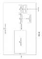
- FIG. 1Athere is shown a block diagram depicting an architecture for implementing the present invention in a light-field capture device 809 .
- Examples of light-field capture devices 809include (but are not limited to) light-field still and video cameras.
- FIG. 1Ais merely exemplary, and that other architectures are possible for light-field capture device 809 .
- One skilled in the artwill further recognize that several of the components shown in the configuration of FIG. 1A are optional, and may be omitted or reconfigured.
- device 809may be a light-field camera that includes light field sensor(s) 803 capable of detecting light.
- Light-field data from sensor(s) 803are processed by processing circuitry 804 , and presented as output on output device(s) 812 .
- the output presented on device(s) 812can be 2D projections of light-field data, as generated by processing circuitry 804 .
- device 809also includes input device(s) 811 such as, for example, a touchscreen, buttons, keyboard, pointing device, and/or any combination thereof.
- input device(s) 811such as, for example, a touchscreen, buttons, keyboard, pointing device, and/or any combination thereof.
- a userinteracts with user interface 805 via input device(s) 811 to control the operation of processing circuitry 804 , for example to cause processing circuitry 804 to generate refocused 2D image data from light-field data at different focus depths.
- user interface 805can also allow the user to provide input for controlling any suitable aspects of the operation of camera 800 for capturing, acquiring, storing, and/or processing image data.
- Light-field sensor(s) 303can include physical and/or electronic components for capturing light-field data describing a scene.
- FIGS. 2A through 2Ddepict examples of architectures of light-field sensors 303 according to various embodiments.
- FIG. 2Adepicts an example wherein sensor 803 includes microlens array 802 and digital image sensor 806 .
- FIG. 2Bdepicts another example wherein sensor 803 includes optics 801 , as well as microlens array 802 and digital image sensor 806 .
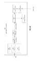
- Optics 801may include, for example, aperture 812 for allowing a selectable amount of light into device 809 , and main lens 813 for focusing light toward microlens array 802 .
- microlens array 802may be disposed and/or incorporated in the optical path of device 809 (between main lens 813 and digital image sensor 806 ) so as to facilitate acquisition, capture, sampling of, recording, and/or obtaining light-field image data via digital image sensor 806 .
- FIG. 1Bthere is shown an example of an architecture for a light-field capture device 809 for implementing the present invention according to one embodiment.
- the Figureis not shown to scale.
- FIG. 1Bshows, in conceptual form, the relationship between aperture 812 , main lens 813 , microlens array 802 , and digital image sensor 806 , as such components interact to capture light-field data for subject 901 .
- device 809may include memory (not shown) for storing image data, such as output by light-field sensor(s) 803 .
- memorycan include external and/or internal memory.
- memorycan be provided at a separate device and/or location from device 809 .
- captured light-field datais provided to processing circuitry 804 .
- Such circuitry 804may be disposed in or integrated into light-field capture device 809 , as shown in FIG. 1A , or it may be in a separate component external to light-field capture device 809 . Such separate component may be local or remote with respect to light-field image capture device 809 .
- Any suitable wired or wireless protocolcan be used for transmitting light-field data to circuitry 804 ; for example device 809 can transmit light-field data and/or other data via the Internet, a cellular data network, a WiFi network, a BlueTooth communication protocol, and/or any other suitable means.
- FIGS. 2C and 2Dalternative embodiments are shown, depicting light-field sensors 803 constructed with arrays of lenses 201 and lens 201 /sensor 806 pairs, respectively.
- FIG. 2Ethere is shown an example of an overall architecture of a light-field capture device 809 wherein optics 801 and microlens array 802 are shown as separate components from light-field sensor(s) 803 , according to one embodiment.
- a usercan capture and view images using light-field capture device 809 as follows.
- a live-view modeis activated, wherein image data captured by sensor(s) 803 and processed by processing circuitry 804 are provided to a display screen or other output device 812 at a video rate (such as, for example, 30 frames per second). Processing can thus occur at a rate compatible with the refresh rate of output device 812 , so as to produce and display a stream of screen-resolution images.
- the usermay press a shutter button to cause device 809 to capture a still image, and the data representing the still image may be separately processed, transferred, and/or stored for later review.
- the contents of the still imagetypically reflect the scene as it was previewed for the user on output device 812 in the displayed real-time live-view stream.
- a variation of thisis device 809 in which pressing the shutter button causes images that have already been read out from sensor 803 and displayed in the live-view stream to be stored; such a device 809 maintains a buffer of recent frames, which are stored when the shutter button is pressed.
- Videocan also be captured.
- the usermay start and stop device 809 as desired, and can cause device 809 to generate an output video file from the read out sensor images.
- Images that have been captured and storedmay be later interacted with and/or viewed, either on-camera (in a so-called “playback” mode), or off-camera, for example on a computing device and/or on the web.
- methods, systems, algorithms, designs, and user interfaces of the present inventioncommunicate to the user of light-field capture device 809 information about the scene during live-view to aid the user in capturing light-field images that provide improved capability to generate 2D images with increased refocusing ability, increased parallax and perspective shifting ability, increased stereo disparity, and/or more dramatic post-capture effects, and/or any suitable combination thereof.
- this techniqueinvolves providing feedback to the user while he or she is capturing light-field images.
- FIGS. 9A through 9Cthere are shown screen shots depicting examples of a user interface for providing information and feedback to aid a user in capturing light-field images.
- FIG. 9Adepicts an example in which the user can change modes from a live view 911 of scene 913 to a playback or still picture mode 912 .
- playback or still picture mode 912information about scene 913 is presented as an overlay on scene 913 itself.
- such informationis presented as indicators 914 of different areas or features of scene 913 that have differing depths.
- Such indicatorscan be color coded and/or otherwise visually distinguished from one another, for example to denote different depths.
- numeric indicators 915can also be displayed, to indicate relative depth of the different areas or features of scene 913 .
- the informationis presented for those features of scene 913 that are at a depth within the refocusable range of the image being captured.
- FIG. 9Bdepicts an example in which information about scene 913 is presented during live view 911 .
- informationis presented as indicators 914 (as well as numeric indicators 915 ) of different areas or features of scene 913 that have differing depths.
- the informationis presented for a subregion 916 of scene 913 , for example that area located near the center of the frame.
- subregion 916is denoted, for example by shading.
- FIG. 9Cdepicts an example in which a matrix-grid analysis is performed to determine depth information for various locations 922 within scene 913 .
- the usercan press a shutter button halfway down to cause information about to be presented scene 913 is presented, as shown in live view 921 as an overlay on scene 913 itself.
- informationis presented as indicators 914 (as well as numeric indicators 915 ) of different areas or features of scene 913 that have differing depths.
- the informationis presented for those locations 922 where some element of the scene is at a depth within the refocusable range of the image being captured.
- the present inventionalso relates to methods, systems, algorithms, designs, and user interfaces for controlling the optics of a light-field capture device to aid the user in successfully composing and capturing light-field data of a scene such that the light-field data may be used to generate 2D output images that encompass the scene objects of interest.
- a set of generated 2D refocused imagescan be generated that contains 2D refocused images where the subject(s) of interest in the scene are sharp and appear “in focus”.
- the system and method of the present inventionprocess captured live-view light-field data to produce 2D live-view image streams.
- These image streamscan be displayed or output, for example on output device(s) 812 such as one or more screens on light-field capture device 809 ; alternatively, the image streams can be transferred and/or output over one or more external interfaces (such as, for example, transmission over HDMI to another display device).
- Light-field data streams acquired by light-field sensor 803may be processed in any of a number of different ways in order to generate 2D images.
- Various embodiments of the present inventionsinclude methods, systems, and algorithms for processing data acquired at a video-rate (such as 30 frames per second) from light-field sensor 803 to generate one or more video-rate 2D image streams for display on light-field capture device 809 itself (such as on one or more LCD screens or other output device(s) 812 ) and/or outputting over external interfaces (such as HDMI ports).
- the 2D image streammay be used as a live-view image stream on the device's LCD screen, so that the 2D image stream displayed is generated in real-time from the light-field data being acquired.
- Each 2D image in the generated image stream(s)may feature one or more of the following aspects:
- different 2D images in the generated image stream(s)may feature different aspects to one another. Specific techniques for generating 2D images having the above-listed characteristics are described in the above-cited related U.S. Patent Applications.
- the decisions as to what processing to apply to the light-field data stream to produce the 2D output image stream(s)are made automatically (and transparently to the user), as described in more detail herein. In at least one other embodiment, these decisions are made in conjunction with user input or direction. Exemplary embodiments of methods for making these decisions under the guidance or direction of the user include (but are not limited to) the following:
- the processing used to generate each image in the output 2D image streammay change over time, including on a per-frame basis.
- the processingis gradually changed over time so that the 2D image stream appears to animate smoothly as different effects are rendered, without noticeable discontinuities in the characteristics of the image stream. Examples of such animations include (but are not limited to) the following:
- the parameters chosen for the generated 2D image stream animationsmay be chosen to be external, such that the resultant animations reflect the maximum capabilities of the acquired light-field data.
- the animationmay refocus between the closest and furthest scene depths which can be sharply brought into focus, or may shift the perspective center between the leftmost and rightmost virtual aperture positions.
- Such animations of the live-view image streamcan convey information to the user about the capabilities of the light-field data being captured.
- any of a plurality of methodscan be used for generating 2D output images from light-field data, including images featuring the effects enumerated herein, and any such method or combination of methods may be employed in conjunction with the techniques of the present invention to generate a 2D live-view image stream from captured live-view light-field data.
- the system and method of the present inventioninclude mechanisms for analyzing captured live-view light-field data, and then in real time communicating information about the light-field data characteristics and the scene being imaged to the user of light-field capture device 809 .
- Light-field dataprovides the capability for the determination of the depths of scene objects.
- depth analysisis performed on the captured live-view light-field data stream, at live-view/video rates; this depth information is then used to aid the user in composing and capturing light-field data.
- the live-view 2D image stream that is displayed on output device(s) 812can be modified to incorporate depth cues. This can be done, for example, by any of the following techniques:
- Modifications to the live-view 2D image streamcan be animated over time. For example, a particular depth slice can be highlighted in each 2D image frame (as described above); the depth which is highlighted can be changed on each subsequent frame. In general, any modifications that can be applied to a single frame may be animated over a series of frames by varying one or more parameters.
- text, graphics, icons, figures, and/or any other annotations or indicatorsare drawn on top of or alongside the live-view 2D image stream display, so as to communicate information about the scene or about the light-field data characteristics. Examples include:
- only portions of the light fielddisplay the visual cues described above. This allows for implementation on a device having limited processing power, where it might be unfeasible to process full-resolution images at video frame-rates.
- the portion of the image to be processed in this mannermay be automatically determined by the camera or selected by the user.
- non-visual cuescan be used to communicate depth and/or scene information to the user. For example a sound can be played, or device 809 can vibrate, based on the refocusable range of the captured light-field data.
- the visual cuesare shown when the user depresses a two-stage shutter button half-way; the live view is then altered as described above. Fully depressing the shutter button then captures and stores the light-field data.
- Other methods of toggling the visual cues on or offcan be used, including those methods that incorporate other sensors on device 809 , such as accelerometers, microphones, and/or other buttons.
- any of the above techniquescan be performed on a captured light-field picture or video stream.
- such techniquescan be performed in a manner that displays more processing-intensive light field quality metrics that cannot be computed in real-time.
- the techniques described hereinare applied to a display being presented on other devices than device 809 , such as computers, tablets, or phones that receive image data from device 809 .
- Light-field datacan be used to generate multiple different perspective views of the same scene (as described in Ng et al.); other methods may be known in the art for calculating depth information from perspective views of a scene. Any such method may be employed in conjunction with the present invention to use depth information to communicate scene information and/or light-field data characteristics to the user.
- depth informationis computed for every point in the scene; in another embodiment, it may only be computed within certain regions and/or for certain scene features.
- the capabilities of the captured light-field data with respect to the set of 2D images of the scene that may be generated from itmay be dependent in part upon the positions and/or configurations of the moving optical elements.
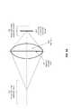
- FIGS. 5A and 5Bthere is shown an example of the relationship between the position of focal plane 504 (as determined by the focus position of main lens 813 ) and the refocusable range of the captured light-field data, according to one embodiment.
- Refocusable rangerefers to the range of scene depths which may be made to appear sharp and “in focus” in generated refocused 2D images for a particular device having particular parameters. This example may be applicable to an architecture such as that depicted in FIG. 2B , wherein the focus of main lens 813 may be varied.
- FIGS. 5A and 5Billustrate the relationship between refocusable range within the world 502 and refocusable range within the camera 503 .
- any of a number of methods and systemscan be implemented for controlling the position and/or configuration of movable optical elements in light-field capture device 809 .
- any or all of the following mechanismscan be used, singly or in any suitable combination:
- any of the following mechanismscan be used:
- depth information for a particular scene subject or locationmay be computed from light-field data using the method described herein.
- the system of the present inventionautomatically determines an appropriate lens focus position for capturing light-field data that can be used to generate 2D images spanning (or attempting to span) that refocusable range. If the desired refocusable range exceeds the range that is possible to capture given the particular light-field capture device being used, then in one embodiment, a range is chosen that is somewhat centered within the desired range.
- the desired real-world refocus rangeis determined 601 , either automatically based on depth positions of objects in the scene, or based on user input or device settings, or by some other mechanism.
- corresponding in-camera displacementsare determined 602 . This can be expressed, for example, as millimeter displacements of light-field sensor's 806 position within the camera.
- a thin lens equationmay be employed to determine the corresponding range limits as in-camera displacements. For example, if the distances from the object to the lens and from the lens to the image are S 1 and S 2 respectively, for a lens of negligible thickness, in air, the distances are related by the following thin lens equation:
- the systemdetermines 603 the average of the near and far sensor displacements to determine 606 the desired focal plane that will center the refocusable range of the captured light-field data on the center of the desired refocusable range.
- the appropriate focus position of the lensis determined 604 , and the lens is automatically moved 605 to the determined focus position.
- zoom positioncan be automatically adjusted to optimize the refocusable range.
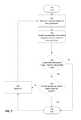
- FIG. 7there is shown a flow diagram depicting a method for automatically adjusting zoom position to perform such optimization.
- the systemdetermined 701 the current zoom position and the focus position of the camera. From this information, it determines 702 the expected refocusable range of captured light-field data at that (zoom, focus) position pair. The system then determines 703 whether this refocusable range is less than the desired refocusable range. If not, the method ends 799 .
- step 703the system zooms out the lens, if possible. This is done by determining 704 whether the zoom position is already at the widest angle supported by lens 813 . If not, a zoom-out operation is performed 705 , and the system repeats steps 701 through 704 . Zooming out 705 causes lens 813 to have a wider angle (shorter focal length), making it possible that the expected refocusable range is now within the desired range. If not, the steps can be repeated until either the expected refocusable range of the light-field data matches or exceeds the desired refocusable range, or the zoom position is at the widest angle supported by lens 813 .
- the cameracan automatically perform a zoom-in operation to increase the focal length and thereby decrease the range of the in-camera displacements needed to cover the real-world refocus range.
- Such automatic zoomingis optional, and can be subject to user settings or approval.
- face detection and analysis of light-field datamay be performed by first generating a 2D image from the light-field data, for example an all-in-focus or extended depth of field (EDOF) image. Any known method(s) can then be used for face detection and analysis of the 2D image.
- the 2D imagecan be generated using techniques described above and in the above-cited related patent applications.
- the depth of the face or other objectmay be determined using any suitable method for determining scene or object depth in light-field data, for example using techniques described above and in the above-cited related patent applications.
- the system and method of the present inventioncan use techniques that do not require any light-field-specific computations. Such embodiments may be useful on light-field capture devices which do not feature the capability to perform light-field processing in real-time at video rates on the captured live-view light-field data.
- FIG. 8Athere is shown a flow diagram depicting an example of a method for using light-field processing in such a manner, specifically to use light-field data for real-time focusing.
- the usermay provide input 852 indicating a location of a subject of interest within the framed scene.
- the usermay touch the screen or otherwise indicate to the camera the location of the subject of interest.
- the cameramay then physically adjust 853 its optical focus so that the subject selected by the user is in optical focus on image sensor 806 .
- the cameramay provide output to communicate to the user that such focusing is taking place, and/or can provide additional output when the focusing operation is complete; such output can be visual (for example via the camera's display and/or LED indicators), auditory (for example by beeps), and/or haptic.
- the usercan interrupt and/or cancel such automatic focusing at any time by pressing the shutter button; this causes the camera to take a picture with the optical focus in whatever state it was when the shutter button was pressed.
- the cameraautomatically adjusts 855 zoom and/or focus settings to keep the same subject in focus despite the changing focal length. This may be accomplished, for example, by determining the current image plane distance from the focus group position in lens 813 , and the current focal length from the zoom group position in lens 813 . From those two values, an object plane distance in the world can be computed. When a new zoom position is set, a new image plane distance can be computed based on the object plane distance and new focal length. The new image plane distance may be converted to a focus group position and a new optical focus may be set to keep the subject in focus.
- FIG. 8Bthere is shown a flow diagram depicting a method for automatic optical focusing 853 by successively reducing focus range based on analysis of light-field data, according to one embodiment.
- An initial focus range for a focus sweepis established 860 ; for example, this initial focus range can be the entire usable focus range of lens 813 .
- the camerathen sweeps 861 through the focus range, for example by moving the focus motor of lens 813 , possibly in fixed amounts, through the focus range.
- Live view framesare read 862 during the sweep; for example, after each step, a live view frame is read out and a region surrounding the specified subject of interest is analyzed 863 . Based on this analysis 863 , the focus range is reduced 864 to more closely specify a range surrounding optimal focus.
- Steps 861 through 864can be performed one or more times, each time reducing the total optical focus range swept as well as the degree to which optical focus is changed per live view frame analyzed.
- the start and stop positions of each sweepdepend on the results of the previous sweep. The number of sweeps may be determined by optimizing for the minimum time required to achieve a desired precision.
- the systemdetermines 866 if the focus range is sufficiently small; if not, it reduces 867 the focus range and repeats steps 861 to 864 .
- FIG. 8Cthere is shown a flow diagram depicting a method for performing analysis step 863 for automatic focusing, according to one embodiment.
- the image datais down-sampled 870 to increase the signal-to-noise ratio.
- the imageis then filtered 871 using a high-pass filter.
- a numeric scoreis generated 872 from the results of the high-pass filter; this score represents how much in-focus information is contained in the region surrounding the subject.
- the focus position corresponding to best optical focusis then determined, for example by interpolating 873 from focus positions corresponding to peak scoring frames based on their scores.
- down-sampling 870 and filtering 871may be performed on one or more color channels of the live-view image, for example the green channel.
- a convolution box filtermay first be applied to the analysis region, and the result may be sub-sampled to produce a smaller single-channel version of the analysis region.
- f ( x,y )
- p(x,y)is the pixel value at coordinates x and y
- sis the filter “step”
- f(x,y)is the resulting filtered pixel value.
- the numeric focus scoremay be generated by computing:
- the sweepcan be interrupted early based on detection that the local numerical derivative of focus scores exceeds a certain threshold.
- appssoftware applications
- appsinclude native iOS and Android camera applications, in addition to third-party applications including Instagram, Hipstamatic, and many others.
- Devices that run such applicationsinclude, for example, Apple's iPhone and iPad, and Google's Android devices,
- light-field capture devicesrecord light-field data rather than standard 2D data.
- a mobile devicewhich is also a light-field capture device may be able to run applications that are compatible with a standard 2D camera, but are not able to operate with light-field data.
- the system of the present inventionprocesses acquired light-field data to generate 2D images for use with apps. Such processing may be performed using techniques described above and in the above-cited related patent applications.
- the system and method of the present inventioninclude functionality for enabling photographic and imaging software that runs on devices with standard 2D cameras to also transparently run on light-field capture devices.
- such embodimentscan integrate the processing of light-field data into the camera software of mobile devices in such a way that the standard interfaces and APIs exposed to applications running on the device operate in the manner expected for a device with only standard 2D cameras.
- FIG. 3Athere is shown an example of a 2D image capture device 300 in which acquired 2D sensor images 301 are processed by 2D image pipeline 302 and passed to application software 303 running on device 300 , according to one embodiment.
- Application software 303may perform any desired operations 304 on the 2D images, including for example, further processing, displaying, sharing, transferring, posting, and/or storing the images.
- FIG. 3Bthere is shown an example 3B of a light-field capture device 809 using both 2D image processing and light-field processing to generate 2D output images from acquired light-field data, and to present such images in a format compatible with application software, according to one embodiment.
- the same 2D camera application software 303runs on device 809 .
- the image datais light-field data 311 .
- device 809makes decisions 312 as to which 2D images should be generated from captured light-field data 311 . Such decisions can be made based on any suitable factors.
- Light-field processing 313is performed in connection with 2d image processing pipeline 302 to generate 2D output images from the acquired light-field data and present them in a format that is readable by application software 303 .
- Application software 303may perform any desired operations 304 on the 2D images, including for example, further processing, displaying, sharing, transferring, posting, and/or storing the images. Both live-view/video and still captures are supported by this technique.
- directionsmay be provided to light-field data processing 313 to specify which 2D images to generate from light-field data 311 .
- Such directionsmay be based on user input and/or on automated analysis.
- the system and method of the present inventioncan generate and record a plurality of 2D video streams from light-field data on a light-field capture device.
- FIG. 4there is shown an example of an architecture for generating and recording a plurality of 2D video streams in this manner.
- processing circuitry 804operates on light-field data received from light-field sensor(s) 803 , to generate any suitable number of 2D video stream(s) 402 .
- User inputprovided via any suitable user input device(s) 811 such as a touchscreen, buttons, and/or the like, can be used to control or affect the operation of processing circuitry 804 .
- user preferences 401may also be used, as specified by the user in a preferences screen, or as provided based on defaults.
- processing circuitry 804can use any suitable method of generating 2D images from light-field data, including (but not limited to) those described above and in related cross-referenced applications. These techniques generate a live-view 2D output image stream, and can therefore be employed for generating and recording one or more 2D video stream(s) 402 , where each generated stream may be generated using different methods and/or parameters.
- the decision about what processing to apply to the captured light-field data to produce each output 2D imagemay be made automatically (for example based on user preferences 401 and/or other factors) and/or may be made according to directions given by the user and detected at user input device 811 .
- user preferences 401may include any settings or preferences that may be set prior to video recording and that may specify, for example, the number of output 2D video streams 402 along with the methods used to generate them.
- the usermay specify that one output stream 402 should be refocused such that infinity is made sharply in focus, a second output video stream is all-in-focus, and a third output video stream is all-in-focus and also in stereo 3D for viewing on a 3D TV or similar 3D display.
- any suitable user inputcan be provided to user input device 811 .
- the user inputmay specify the number of output 2D video streams along with the methods used to generate them. For example, the user may touch the screen at a plurality of locations to specify objects that should be tracked, and a separate 2D video stream may be generated and recorded for each tracked object in which it appears sharp and in focus.
- the light-field data itselfmay or may not be recorded in addition to the generated 2D video streams 402 .
- the present inventioncan be implemented as a system or a method for performing the above-described techniques, either singly or in any combination.
- the present inventioncan be implemented as a computer program product comprising a nontransitory computer-readable storage medium and computer program code, encoded on the medium, for causing a processor in a computing device or other electronic device to perform the above-described techniques.
- Certain aspects of the present inventioninclude process steps and instructions described herein in the form of an algorithm. It should be noted that the process steps and instructions of the present invention can be embodied in software, firmware and/or hardware, and when embodied in software, can be downloaded to reside on and be operated from different platforms used by a variety of operating systems.
- the present inventionalso relates to an apparatus for performing the operations herein.
- This apparatusmay be specially constructed for the required purposes, or it may comprise a general-purpose computing device selectively activated or reconfigured by a computer program stored in the computing device.
- a computer programmay be stored in a computer readable storage medium, such as, but is not limited to, any type of disk including floppy disks, optical disks, CD-ROMs, magnetic-optical disks, read-only memories (ROMs), random access memories (RAMs), EPROMs, EEPROMs, flash memory, solid state drives, magnetic or optical cards, application specific integrated circuits (ASICs), or any type of media suitable for storing electronic instructions, and each coupled to a computer system bus.
- the computing devices referred to hereinmay include a single processor or may be architectures employing multiple processor designs for increased computing capability.
- the present inventioncan be implemented as software, hardware, and/or other elements for controlling a computer system, computing device, or other electronic device, or any combination or plurality thereof.
- an electronic devicecan include, for example, a processor, an input device (such as a keyboard, mouse, touchpad, trackpad, joystick, trackball, microphone, and/or any combination thereof), an output device (such as a screen, speaker, and/or the like), memory, long-term storage (such as magnetic storage, optical storage, and/or the like), and/or network connectivity, according to techniques that are well known in the art.
- Such an electronic devicemay be portable or nonportable.
- Examples of electronic devices that may be used for implementing the inventioninclude: a mobile phone, personal digital assistant, smartphone, kiosk, server computer, enterprise computing device, desktop computer, laptop computer, tablet computer, consumer electronic device, television, set-top box, or the like.
- An electronic device for implementing the present inventionmay use any operating system such as, for example: Linux; Microsoft Windows, available from Microsoft Corporation of Redmond, Wash.; Mac OS X, available from Apple Inc. of Cupertino, Calif.; iOS, available from Apple Inc. of Cupertino, Calif.; and/or any other operating system that is adapted for use on the device.
Landscapes
- Engineering & Computer Science (AREA)
- Multimedia (AREA)
- Signal Processing (AREA)
- Computing Systems (AREA)
- Theoretical Computer Science (AREA)
- Studio Devices (AREA)
Abstract
Description
- Communicating to the user of the light-field capture device information about the scene during live-view to aid him or her in capturing light-field images that provide improved capability to generate 2D images with increased refocusing ability, increased parallax and perspective shifting ability, increased stereo disparity, and/or more dramatic post-capture effects.
- Control of camera optical elements (for example in camera lenses with moving zoom or focus motors) during live-view and capture to facilitate the user's ease of composition and capture of light-field data for a scene, so that the resultant light-field data can be used to generate a set of 2D output images that encompass the scene objects of interest.
- Presenting a standard 2D camera interface to software running on the light-field capture device to enable such software to function normally without needing to be modified to handle the fact that the device is actually capturing light-field data.
- Generating a plurality of 2D video streams that are derived from the stream of light-field data that is produced by the light-field capture device, where the 2D video streams are interoperable with standard video players and are generated automatically and/or under the user's guidance or direction to provide certain effects such as refocusing, parallax or perspective shifting, all-in-focus, depth-based processing, and/or any other effect that can be generated by processing light-field data.
- live-view capture: the acquisition of data from one or more sensors at real-time, video, and/or live-view rates, which may occur on a continuous basis and which does not result in the acquired data being stored for later review.
- still capture: the acquisition of data as a result of user input, such as for example pressing a shutter button, where the acquired data is transferred or stored for later review.
- video capture: the continuous acquisition of data that is transferred or stored as a video stream for later review, where the video capture occurs over some specific time interval for example as demarked by the user pressing the shutter button to start and stop the capture activity.
- capture: can refer to either or both of still capture or video capture.
- pre-capture processing or live-view processing: operations that are performed in real-time on acquired live-view data.
- post-capture processing: operations that are performed on stored or transferred acquired data, rather than on the real-time live-view acquired data.
- captured live-view data: data that is acquired during live-view operation and which may be processed and/or displayed as part of the real-time live-view mode of operation.
- captured data: data that is acquired as part of a still or video capture operation and which may be transferred or stored for later review.
- image: a two-dimensional array of pixel values, or pixels, each specifying a color.
- light-field image: an image that contains a representation of light field data captured at the sensor.
- microlens: a small lens, typically one in an array of similar microlenses.
- refocusable range: the range of scene depths which may be made to appear sharp and “in focus” in generated refocused 2D images for a particular device having particular parameters.
- Processing light-field data read from sensor(s)803 at video rates to display to the user a live-view image stream of processed 2D images, where the method for generating the 2D images is chosen to aid the user in composing a light-field capture of a scene and may be user-specified, automatically determined, or a combination of these.
- Analyzing light-field data read from the light-field capture device's sensor(s) at video rates to convey to the user information about the scene being imaged and about the characteristics of the light-field data being captured, where such information may be communicated to the user by any suitable means supported by the device.
- Analyzing the light field at non-video frame rates at the request of
sensor 803. For example, in at least one embodiment, if the shutter button is held halfway down, the last frame shown is analyzed and light-field characteristics are displayed. Such information may include directions as to how to improve these characteristics; the information may be communicated by any suitable means supported bydevice 809. - Analyzing captured light fields and displaying light-field characteristics in playback mode. For example,
device 809 can be configured to display light-field characteristics for captured light-field data after capture has occurred. In at least one embodiment, this playback mode can take place on a device other than light-field capture device 809. For example, the image data can be transferred to a computer, tablet, or phone, and the light-field characteristics can be displayed while image data is being played back on that device. - Controlling light-field capture device's809 optical elements to aid the user in the composition and capture of light-field data.
- The 2D image may be refocused to a particular scene depth, and the scene depth to which it is refocused may be the same as or different from the scene depth which is optically in focus.
- The 2D image may be refocused to an arbitrary focus surface, for example to simulate a tilt/shift lens.
- The 2D image may be generated from a particular perspective view or parallax shift.
- The 2D image may be all-in-focus or have extended depth of field (EDOF).
- The 2D image may be stereo or otherwise rendered for 3D display/viewing, with a zero-parallax plane as one of the parameters of this rendering mode.
- The 2D image may have been filtered or modified according to the depths of objects in the scene; exemplary embodiments of such filtering or modification are described below.
- The 2D image may be generated from the acquired light-field data using any other method for producing a 2D image.
- The 2D image may contain a plurality of image regions, each of which may feature one or more of these aspects.
- The user may indicate his or her subject or region of interest by providing input via input device(s)811; this may include, for example, touching the screen or performing any other action(s) detectable by input device(s)811. Input device(s)811 may be of any suitable type, so as to enable techniques such as eye-tracking, stylus gesture input, voice commands, and/or the like. The light-field data is refocused to generate a 2D image stream that gives the appearance of bringing the corresponding subject or region (as designated by the user input) into focus.
- The user may specify via touchscreen or other input that the light-field data should be refocused to a particular depth, for example the closest or furthest distance that can be brought sharply into focus, so as to generate a 2D image stream that gives the appearance of bringing that subject or region into focus.
- In at least one embodiment, light-
field capture device 809 includes an accelerometer or other movement-sensing component. The user may move, shake, or tilt light-field capture device 809 to cause it to generate a 2D image stream featuring perspective or parallax shifts or any other suitable effect(s).
- Gradually changing the depth of the refocus operation, so that the 2D image stream appears to change its focus over time; this effect can give the appearance of physically changing the focus on a conventional 2D camera.
- Gradually changing the perspective view or parallax shift over time so that the 2D image stream appears to change its viewpoint of the scene.
- Overlaying a depth map on top of the live-
view 2D image stream. The depth map may be semi-transparent and blended with the live-view images, or it may be opaque and replace them entirely - Filtering the live-
view 2D image stream such that each pixel is processed based on its depth and/or on the depth of its local region to change the brightness or color of the pixel in a depth-dependent manner. For example:- The intensity and/or color of pixels can be changed depending on whether the corresponding scene locations are within or not within the light-field data's refocusable range. For example, scene locations outside the range may be “grayed out”.
- The intensity or color of pixels corresponding to a particular scene depth can be changed. For example, colors can be changed for pixels corresponding to a scene depth which is currently being displayed as sharply in focus, or any other scene depth. These can be, presented, for example, as depth slices, isocontours, isosurfaces, or the like.
- The intensity and/or color of pixels can be changed as a function of their depth relative to the scene depth which is currently being displayed as sharply in focus. For example, those pixels having a depth that is closer to the currently-sharp depth can be shown at a different intensity and/or color than those having depth that is farther away from the currently-sharp depth.
- Highlighting objects in the scene, adding a halo around/behind foreground objects, and the like.
- Overlaying a depth map on top of the live-
- Labeling certain scene features with a numeric score or a text or graphic label, to indicate their relative depth in the scene. Any suitable label can be presented, so as to describe or indicate whether a given scene object is within the refocusable range of the light-field data.
- Presenting a “depth histogram” that classifies pixels in the scene according to their depths.
- Presenting a graph showing the output image resolution as a function of relative depth, with objects in the scene being indicated as marks on this graph.
- Tracking a feature or object within the scene, and continuously updating a label indicating its scene depth.
- Coupling face detection with depth analysis, for example by drawing rectangles around identified faces, and color-coding the rectangle according to scene depth.
- Refocusable-to-infinity tracking: For any zoom position of
device 809, the focus position of the optics can be set such that the captured light-field data permits refocusing out to optical infinity. By positioning refocusable range502 such that a point within its refocusable range reaches optical infinity, light-field data captured at this lens configuration will be refocusable from infinity down to a minimum close distance. In one embodiment, optical infinity is set to the furthest point in refocusable range502 in order to maximize the total depth ofrefocusable range 502. In another embodiment, optical infinity is set to a specific location withinrefocusable range 502. - Macro mode: For any zoom position of
device 809, the focus position can be set to the furthest position such that a desired minimum close distance, for example the front surface ofmain lens 813, is within the refocusing range of the light-field data. - Tap-to-select-subject: The user may touch the screen during live-view to indicate a subject of interest, and the camera adjusts the focus position of
lens 813 such that the specified subject is within the refocusable range of the captured light-field data. The refocusable range may be chosen (by choosing the focus position) in one of several ways (which may be selected via user preferences, or automatically by the camera), including for example:- Positioning the specified subject at the near or far extreme of the refocusable range.
- Positioning the specified subject close to the middle of the refocusable range.
- Subject tracking: Given an identified subject of interest (e.g. by the user tapping the screen), subsequent zoom position changes may be made by the user while keeping the desired subject within the refocusable range, and in particular, while keeping the same subject in focus throughout the zoom position changes, by changing the focus position appropriately in tandem with changes to the zoom position.
- Multi-subject bracketing: The user may identify a plurality of scene subjects, for example by touching the screen in multiple locations, and the camera automatically adjusts the movable optical elements in order to ensure that all desired subjects are within the refocusable range of captured light-field data. Such adjustments may include:
- Changing the focus position to best bracket all selected scene subjects within the refocusable range.
- Changing both the zoom and focus positions to best attempt to bracket all selected scene subjects within the refocusable range. Note that by changing the zoom position, the field of view and depth of field of the scene are changed, and the camera may employ heuristics to choose the best zoom and focus positions such as the following:
- Zoom in as far as possible such that (1) all specified subjects of interest are within the field of view and (2) the focus position may be set such that all subjects of interest are within the refocusable range.
- Zoom out only to the extent needed to allow the focus position to be set such that all specified subjects of interest are within the refocusable range.
- Automatic scene bracketing: The camera analyzes the scene and automatically determines which focus position would result in the contents of the entire scene, or the contents of selected regions of the scene (e.g. a center rectangle), being best bracketed by the refocusable range of captured light-field data.
- Automatic face bracketing: The camera analyzes the scene and detect human faces, and then automatically chooses the zoom and/or focus position such that one or more faces are placed within the refocusable range of the light-field data. The choice of which faces to bracket may be made in any of a number of ways, including (but not limited to) the following:
- Bracket faces of people that are friends or acquaintances of the user.
- Bracket faces that are in the foreground, where the foreground may be defined as scene depths that are not close to optical infinity.
- Bracket faces that are near the center of the image.
- Bracket faces that are large or prominently featured in the scene.
- Balancing live-view optical focusing and software refocusing: The subject of the scene that appears in focus in a live-view image stream is a product of two variables: which scene depth is optically in focus when capturing the light-field data, and which scene depth is subsequently refocused to by using the light-field data. The user may interact with the camera, for example by tapping the screen, to specify what subject should be in focus in the live-view image stream, and the camera may control the optical focus position and the refocusing depth as coupled variables to keep the subject visually in focus on the screen. Given this coupling, the camera may employ the following (or any other) strategies to control the focus position of the captured light-field data:
- Optically focus the camera such that the visually in-focus subject is at the near or far extreme of the refocusing range.
- Optically focus the camera such that the visually in-focus subject is somewhat close to the center of the refocusing range.
- Refocusable-to-infinity tracking: For any zoom position of
- Specification of the subject is interpreted as a one-time specification of a camera-relative depth value. Subsequent changes to the camera's position, orientation, focus, or zoom have no effect on the retained depth value. In this embodiment, “tracking the subject” means making adjustments that are consistent with the retained depth value. For example, when the camera changes the lens' focus position to “track a subject” and to keep it appearing sharp and in focus on the display as the user is changing the zoom position, in this embodiment, the camera acts to keep the specified or determined depth in focus.
- Specification of the subject is interpreted as a one-time specification of a spatial coordinate either in the camera's field of view or on the camera's screen. Analyses performed over time on live-view frames are performed by the camera at this spatial coordinate, regardless of whether the contents of the scene are changing. In the case of the coordinate referring to a position in the camera's field of view, as the camera changes its zoom position and hence changes the imaged field of view, the coordinate is updated accordingly.
- The “subject” is interpreted by the camera as an object in the scene, for example any scene feature such as a human face, and the camera tracks the subject even as it moves within the scene, rather than just using its scene depth at the time that the subject was specified or determined.
Implementation of Subject Depth Determination from Light-Field Data
f(x,y)=|2p(x,y)−p(x,y−s)−p(x,y+s)|+|2p(x,y)−p(x−s,y)−p(x+s,y)| (Eq. 2)
where p(x,y) is the pixel value at coordinates x and y, s is the filter “step”, and f(x,y) is the resulting filtered pixel value. The numeric focus score may be generated by computing:
Claims (54)
Priority Applications (2)
| Application Number | Priority Date | Filing Date | Title |
|---|---|---|---|
| US13/774,986US8995785B2 (en) | 2012-02-28 | 2013-02-22 | Light-field processing and analysis, camera control, and user interfaces and interaction on light-field capture devices |
| US13/867,333US9456141B2 (en) | 2013-02-22 | 2013-04-22 | Light-field based autofocus |
Applications Claiming Priority (6)
| Application Number | Priority Date | Filing Date | Title |
|---|---|---|---|
| US201261604175P | 2012-02-28 | 2012-02-28 | |
| US201261604195P | 2012-02-28 | 2012-02-28 | |
| US201261604155P | 2012-02-28 | 2012-02-28 | |
| US201261655790P | 2012-06-05 | 2012-06-05 | |
| US13/688,026US8811769B1 (en) | 2012-02-28 | 2012-11-28 | Extended depth of field and variable center of perspective in light-field processing |
| US13/774,986US8995785B2 (en) | 2012-02-28 | 2013-02-22 | Light-field processing and analysis, camera control, and user interfaces and interaction on light-field capture devices |
Related Parent Applications (1)
| Application Number | Title | Priority Date | Filing Date |
|---|---|---|---|
| US13/688,026Continuation-In-PartUS8811769B1 (en) | 2012-02-28 | 2012-11-28 | Extended depth of field and variable center of perspective in light-field processing |
Related Child Applications (1)
| Application Number | Title | Priority Date | Filing Date |
|---|---|---|---|
| US13/867,333Continuation-In-PartUS9456141B2 (en) | 2013-02-22 | 2013-04-22 | Light-field based autofocus |
Publications (2)
| Publication Number | Publication Date |
|---|---|
| US20130222633A1 US20130222633A1 (en) | 2013-08-29 |
| US8995785B2true US8995785B2 (en) | 2015-03-31 |
Family
ID=49002480
Family Applications (1)
| Application Number | Title | Priority Date | Filing Date |
|---|---|---|---|
| US13/774,986Active2033-02-16US8995785B2 (en) | 2012-02-28 | 2013-02-22 | Light-field processing and analysis, camera control, and user interfaces and interaction on light-field capture devices |
Country Status (1)
| Country | Link |
|---|---|
| US (1) | US8995785B2 (en) |
Cited By (36)
| Publication number | Priority date | Publication date | Assignee | Title |
|---|---|---|---|---|
| US20140071305A1 (en)* | 2012-09-12 | 2014-03-13 | Canon Kabushiki Kaisha | Image pickup apparatus, image pickup system, image processing device, and method of controlling image pickup apparatus |
| US20140176592A1 (en)* | 2011-02-15 | 2014-06-26 | Lytro, Inc. | Configuring two-dimensional image processing based on light-field parameters |
| US20150358529A1 (en)* | 2014-06-04 | 2015-12-10 | Canon Kabushiki Kaisha | Image processing device, its control method, and storage medium |
| US20170078578A1 (en)* | 2015-09-10 | 2017-03-16 | Canon Kabushiki Kaisha | Image capture apparatus and method of controlling the same |
| WO2017063556A1 (en)* | 2015-10-12 | 2017-04-20 | 得能创科有限公司 | Method and system for automatically realizing lamp control scenario |
| US9639945B2 (en) | 2015-08-27 | 2017-05-02 | Lytro, Inc. | Depth-based application of image effects |
| US9858649B2 (en) | 2015-09-30 | 2018-01-02 | Lytro, Inc. | Depth-based image blurring |
| US10205896B2 (en) | 2015-07-24 | 2019-02-12 | Google Llc | Automatic lens flare detection and correction for light-field images |
| US10275898B1 (en) | 2015-04-15 | 2019-04-30 | Google Llc | Wedge-based light-field video capture |
| US10275892B2 (en) | 2016-06-09 | 2019-04-30 | Google Llc | Multi-view scene segmentation and propagation |
| US10298834B2 (en) | 2006-12-01 | 2019-05-21 | Google Llc | Video refocusing |
| US10334151B2 (en) | 2013-04-22 | 2019-06-25 | Google Llc | Phase detection autofocus using subaperture images |
| US10341632B2 (en) | 2015-04-15 | 2019-07-02 | Google Llc. | Spatial random access enabled video system with a three-dimensional viewing volume |
| US10354399B2 (en) | 2017-05-25 | 2019-07-16 | Google Llc | Multi-view back-projection to a light-field |
| US10412373B2 (en) | 2015-04-15 | 2019-09-10 | Google Llc | Image capture for virtual reality displays |
| US10419737B2 (en) | 2015-04-15 | 2019-09-17 | Google Llc | Data structures and delivery methods for expediting virtual reality playback |
| US10440407B2 (en) | 2017-05-09 | 2019-10-08 | Google Llc | Adaptive control for immersive experience delivery |
| US10444931B2 (en) | 2017-05-09 | 2019-10-15 | Google Llc | Vantage generation and interactive playback |
| US10469873B2 (en) | 2015-04-15 | 2019-11-05 | Google Llc | Encoding and decoding virtual reality video |
| US10474227B2 (en) | 2017-05-09 | 2019-11-12 | Google Llc | Generation of virtual reality with 6 degrees of freedom from limited viewer data |
| US10540818B2 (en) | 2015-04-15 | 2020-01-21 | Google Llc | Stereo image generation and interactive playback |
| US10546424B2 (en) | 2015-04-15 | 2020-01-28 | Google Llc | Layered content delivery for virtual and augmented reality experiences |
| US10545215B2 (en) | 2017-09-13 | 2020-01-28 | Google Llc | 4D camera tracking and optical stabilization |
| US10567464B2 (en) | 2015-04-15 | 2020-02-18 | Google Llc | Video compression with adaptive view-dependent lighting removal |
| US10565734B2 (en) | 2015-04-15 | 2020-02-18 | Google Llc | Video capture, processing, calibration, computational fiber artifact removal, and light-field pipeline |
| US10594945B2 (en) | 2017-04-03 | 2020-03-17 | Google Llc | Generating dolly zoom effect using light field image data |
| US10679361B2 (en) | 2016-12-05 | 2020-06-09 | Google Llc | Multi-view rotoscope contour propagation |
| US10965862B2 (en) | 2018-01-18 | 2021-03-30 | Google Llc | Multi-camera navigation interface |
| US11074444B2 (en) | 2017-04-21 | 2021-07-27 | Advanced New Technologies Co., Ltd. | Method and apparatus for use in previewing during iris recognition process |
| US11202052B2 (en)* | 2017-06-12 | 2021-12-14 | Interdigital Ce Patent Holdings, Sas | Method for displaying, on a 2D display device, a content derived from light field data |
| US20220086321A1 (en)* | 2020-09-15 | 2022-03-17 | Micron Technology, Inc. | Reduced diffraction micro lens imaging |
| US11328446B2 (en) | 2015-04-15 | 2022-05-10 | Google Llc | Combining light-field data with active depth data for depth map generation |
| US11388388B2 (en)* | 2020-12-01 | 2022-07-12 | Looking Glass Factory, Inc. | System and method for processing three dimensional images |
| US11415935B2 (en) | 2020-06-23 | 2022-08-16 | Looking Glass Factory, Inc. | System and method for holographic communication |
| US11589034B2 (en) | 2017-06-12 | 2023-02-21 | Interdigital Madison Patent Holdings, Sas | Method and apparatus for providing information to a user observing a multi view content |
| US11754975B2 (en) | 2020-05-21 | 2023-09-12 | Looking Glass Factory, Inc. | System and method for holographic image display |
Families Citing this family (66)
| Publication number | Priority date | Publication date | Assignee | Title |
|---|---|---|---|---|
| US10086265B2 (en)* | 2008-07-11 | 2018-10-02 | Disney Enterprises, Inc. | Video teleconference object enable system |
| JP5968107B2 (en)* | 2011-09-01 | 2016-08-10 | キヤノン株式会社 | Image processing method, image processing apparatus, and program |
| US9165401B1 (en) | 2011-10-24 | 2015-10-20 | Disney Enterprises, Inc. | Multi-perspective stereoscopy from light fields |
| US9113043B1 (en)* | 2011-10-24 | 2015-08-18 | Disney Enterprises, Inc. | Multi-perspective stereoscopy from light fields |
| US8948545B2 (en)* | 2012-02-28 | 2015-02-03 | Lytro, Inc. | Compensating for sensor saturation and microlens modulation during light-field image processing |
| US8995785B2 (en)* | 2012-02-28 | 2015-03-31 | Lytro, Inc. | Light-field processing and analysis, camera control, and user interfaces and interaction on light-field capture devices |
| JP5938281B2 (en)* | 2012-06-25 | 2016-06-22 | キヤノン株式会社 | Imaging apparatus, control method therefor, and program |
| US9124762B2 (en) | 2012-12-20 | 2015-09-01 | Microsoft Technology Licensing, Llc | Privacy camera |
| JP2014157425A (en)* | 2013-02-14 | 2014-08-28 | Canon Inc | Imaging device and control method thereof |
| JP6335434B2 (en)* | 2013-04-19 | 2018-05-30 | キヤノン株式会社 | Imaging apparatus, control method thereof, and program |
| WO2014209279A1 (en)* | 2013-06-25 | 2014-12-31 | Intel Corporation | Management and access of media with media capture device operator perception data |
| JP6061816B2 (en)* | 2013-08-22 | 2017-01-18 | キヤノン株式会社 | IMAGING DEVICE, IMAGING DEVICE CONTROL METHOD, PROGRAM, AND STORAGE MEDIUM |
| US9292906B1 (en)* | 2013-09-06 | 2016-03-22 | Google Inc. | Two-dimensional image processing based on third dimension data |
| US20150104101A1 (en)* | 2013-10-14 | 2015-04-16 | Apple Inc. | Method and ui for z depth image segmentation |
| JP6262984B2 (en)* | 2013-10-18 | 2018-01-17 | キヤノン株式会社 | Image processing apparatus, imaging apparatus, control method, and program |
| US8760500B1 (en) | 2013-10-23 | 2014-06-24 | Google Inc. | Depth map generation |
| EP2887642A3 (en) | 2013-12-23 | 2015-07-01 | Nokia Corporation | Method, apparatus and computer program product for image refocusing for light-field images |
| US10244223B2 (en) | 2014-01-10 | 2019-03-26 | Ostendo Technologies, Inc. | Methods for full parallax compressed light field 3D imaging systems |
| KR102326275B1 (en)* | 2014-02-25 | 2021-11-16 | 삼성전자주식회사 | Image displaying method and apparatus |
| WO2015137635A1 (en)* | 2014-03-13 | 2015-09-17 | Samsung Electronics Co., Ltd. | Image pickup apparatus and method for generating image having depth information |
| KR102257620B1 (en)* | 2014-03-20 | 2021-05-28 | 엘지전자 주식회사 | Display device and method for controlling the same |
| KR102271853B1 (en)* | 2014-03-21 | 2021-07-01 | 삼성전자주식회사 | Electronic apparatus, image processing method, and computer-readable recording medium |
| JP6341736B2 (en) | 2014-04-16 | 2018-06-13 | キヤノン株式会社 | Imaging apparatus, control method, program, storage medium |
| KR20170031700A (en)* | 2014-07-15 | 2017-03-21 | 오스텐도 테크놀로지스 인코포레이티드 | Preprocessor for full parallax light field compression |
| US9646365B1 (en) | 2014-08-12 | 2017-05-09 | Amazon Technologies, Inc. | Variable temporal aperture |
| US9787899B1 (en) | 2014-08-12 | 2017-10-10 | Amazon Technologies, Inc. | Multiple captures with a variable aperture |
| US9749532B1 (en) | 2014-08-12 | 2017-08-29 | Amazon Technologies, Inc. | Pixel readout of a charge coupled device having a variable aperture |
| GB2544946B (en) | 2014-08-31 | 2021-03-10 | Berestka John | Systems and methods for analyzing the eye |
| US9967451B2 (en)* | 2014-09-30 | 2018-05-08 | Canon Kabushiki Kaisha | Imaging apparatus and imaging method that determine whether an object exists in a refocusable range on the basis of distance information and pupil division of photoelectric converters |
| EP3059949A1 (en) | 2015-02-23 | 2016-08-24 | Thomson Licensing | Method and apparatus for generating lens-related metadata |
| EP4386659A1 (en) | 2015-03-10 | 2024-06-19 | Canon Kabushiki Kaisha | Image processing method, image processing device, and image pickup apparatus |
| US11240421B2 (en) | 2015-04-10 | 2022-02-01 | Qualcomm Incorporated | Methods and apparatus for defocus reduction using laser autofocus |
| US9693038B2 (en)* | 2015-04-21 | 2017-06-27 | Hand Held Products, Inc. | Systems and methods for imaging |
| JP7036599B2 (en) | 2015-04-23 | 2022-03-15 | オステンド・テクノロジーズ・インコーポレーテッド | A method of synthesizing a light field with compressed omnidirectional parallax using depth information |
| KR20170139560A (en) | 2015-04-23 | 2017-12-19 | 오스텐도 테크놀로지스 인코포레이티드 | METHODS AND APPARATUS FOR Fully Differential Optical Field Display Systems |
| EP3089449B1 (en) | 2015-04-30 | 2020-03-04 | InterDigital CE Patent Holdings | Method for obtaining light-field data using a non-light-field imaging device, corresponding device, computer program product and non-transitory computer-readable carrier medium |
| JP6509031B2 (en)* | 2015-05-14 | 2019-05-08 | キヤノン株式会社 | Image processing apparatus, image processing method and imaging apparatus |
| JP2016219991A (en)* | 2015-05-19 | 2016-12-22 | キヤノン株式会社 | Image processor and control method thereof and program |
| WO2016191035A1 (en) | 2015-05-26 | 2016-12-01 | Lytro, Inc. | Capturing light-field images with uneven and/or incomplete angular sampling |
| EP3099055A1 (en) | 2015-05-29 | 2016-11-30 | Thomson Licensing | Method and apparatus for displaying a light field based image on a user's device, and corresponding computer program product |
| EP3099054A1 (en) | 2015-05-29 | 2016-11-30 | Thomson Licensing | Method and apparatus for determining a focal stack of images from light field data associated with a scene, and corresponding computer program product |
| EP3099078A1 (en) | 2015-05-29 | 2016-11-30 | Thomson Licensing | Method for collecting information on users of 4d light field data, corresponding apparatuses and computer programs |
| EP3104604A1 (en) | 2015-06-08 | 2016-12-14 | Thomson Licensing | Light field imaging device |
| EP3104593A1 (en) | 2015-06-08 | 2016-12-14 | Thomson Licensing | Light field imaging device |
| US20170054897A1 (en)* | 2015-08-21 | 2017-02-23 | Samsung Electronics Co., Ltd. | Method of automatically focusing on region of interest by an electronic device |
| EP3139614A1 (en) | 2015-09-07 | 2017-03-08 | Thomson Licensing | Method and device for encoding and decoding a light field based image, and corresponding computer program product |
| EP3142365A1 (en) | 2015-09-14 | 2017-03-15 | Thomson Licensing | Method and apparatus for encoding and decoding a light field based image, and corresponding computer program product |
| EP3142366A1 (en) | 2015-09-14 | 2017-03-15 | Thomson Licensing | Method and apparatus for encoding and decoding a light field based image, and corresponding computer program product |
| EP3144889A1 (en) | 2015-09-17 | 2017-03-22 | Thomson Licensing | Method and system for calibrating an image acquisition device and corresponding computer program product |
| EP3147860A1 (en) | 2015-09-28 | 2017-03-29 | Thomson Licensing | Method and apparatus for reducing the coding artefact of a light field based image, and corresponding computer program product |
| US10448030B2 (en) | 2015-11-16 | 2019-10-15 | Ostendo Technologies, Inc. | Content adaptive light field compression |
| EP3171598A1 (en) | 2015-11-19 | 2017-05-24 | Thomson Licensing | Methods and devices for encoding and decoding a matrix of views obtained from light-field data, corresponding computer program and non-transitory program storage device |
| EP3624050B1 (en) | 2015-12-16 | 2021-11-24 | InterDigital CE Patent Holdings | Method and module for refocusing at least one plenoptic video |
| EP3182372B1 (en) | 2015-12-18 | 2019-07-31 | InterDigital CE Patent Holdings | Method and system for estimating the position of a projection of a chief ray on a sensor of a light-field acquisition device |
| EP3185560A1 (en) | 2015-12-23 | 2017-06-28 | Thomson Licensing | System and method for encoding and decoding information representative of a bokeh model to be applied to an all-in-focus light-field content |
| JP6700813B2 (en)* | 2016-01-29 | 2020-05-27 | キヤノン株式会社 | Image processing device, imaging device, image processing method, and program |
| EP3203742A1 (en) | 2016-02-02 | 2017-08-09 | Thomson Licensing | System and method for encoding and decoding information representative of a focalization distance associated to an image belonging to a focal stack representative of a light field content |
| WO2017143427A1 (en)* | 2016-02-25 | 2017-08-31 | Synaptive Medical (Barbados) Inc. | System and method for scope based depth map acquisition |
| US10453431B2 (en) | 2016-04-28 | 2019-10-22 | Ostendo Technologies, Inc. | Integrated near-far light field display systems |
| EP3288253A1 (en) | 2016-08-25 | 2018-02-28 | Thomson Licensing | Method and apparatus for generating data representative of a bokeh associated to light-field data |
| EP3293959A1 (en) | 2016-09-07 | 2018-03-14 | Thomson Licensing | Plenoptic imaging device equipped with an enhanced optical system |
| EP3331236A1 (en) | 2016-11-30 | 2018-06-06 | Thomson Licensing | Method for rendering a final image from initial images acquired by a camera array, corresponding device, computer program product and computer-readable carrier medium |
| EP3462410A1 (en) | 2017-09-29 | 2019-04-03 | Thomson Licensing | A user interface for manipulating light-field images |
| EP3477595A1 (en) | 2017-10-31 | 2019-05-01 | Thomson Licensing | Method and apparatus for selecting a surface in a light field, and corresponding computer program product |
| CN110764859B (en)* | 2019-10-21 | 2023-06-02 | 三星电子(中国)研发中心 | A method for automatically adjusting and optimizing the display of the visible area of the screen |
| CN116805354B (en)* | 2023-08-23 | 2023-12-29 | 中国林业科学研究院森林生态环境与自然保护研究所(国家林业和草原局世界自然遗产保护研究中心) | Rare bird three-dimensional model reconstruction method and device based on nerve radiation field |
Citations (78)
| Publication number | Priority date | Publication date | Assignee | Title |
|---|---|---|---|---|
| US725567A (en) | 1902-09-25 | 1903-04-14 | Frederic E Ives | Parallax stereogram and process of making same. |
| US4383170A (en) | 1979-11-19 | 1983-05-10 | Tokyo Shibaura Denki Kabushiki Kaisha | Image input device |
| US4661986A (en) | 1983-06-27 | 1987-04-28 | Rca Corporation | Depth-of-focus imaging process method |
| US4694185A (en) | 1986-04-18 | 1987-09-15 | Eastman Kodak Company | Light sensing devices with lenticular pixels |
| US4920419A (en) | 1988-05-31 | 1990-04-24 | Eastman Kodak Company | Zoom lens focus control device for film video player |
| US5076687A (en) | 1990-08-28 | 1991-12-31 | Massachusetts Institute Of Technology | Optical ranging apparatus |
| US5282045A (en) | 1990-04-27 | 1994-01-25 | Hitachi, Ltd. | Depth-of-field control apparatus and image pickup apparatus having the same therein |
| DE19624421A1 (en) | 1995-06-30 | 1997-01-02 | Zeiss Carl Fa | Wave front deformation from object spatially resolved measurement arrangement |
| US5610390A (en) | 1994-10-03 | 1997-03-11 | Fuji Photo Optical Co., Ltd. | Solid-state image pickup device having microlenses each with displaced optical axis |
| US5748371A (en) | 1995-02-03 | 1998-05-05 | The Regents Of The University Of Colorado | Extended depth of field optical systems |
| US5757423A (en) | 1993-10-22 | 1998-05-26 | Canon Kabushiki Kaisha | Image taking apparatus |
| US5949433A (en) | 1996-04-11 | 1999-09-07 | Discreet Logic, Inc. | Processing image data |
| US6023523A (en) | 1996-02-16 | 2000-02-08 | Microsoft Corporation | Method and system for digital plenoptic imaging |
| US6028606A (en) | 1996-08-02 | 2000-02-22 | The Board Of Trustees Of The Leland Stanford Junior University | Camera simulation system |
| US6097394A (en) | 1997-04-28 | 2000-08-01 | Board Of Trustees, Leland Stanford, Jr. University | Method and system for light field rendering |
| US6201899B1 (en) | 1998-10-09 | 2001-03-13 | Sarnoff Corporation | Method and apparatus for extended depth of field imaging |
| US6320979B1 (en) | 1998-10-06 | 2001-11-20 | Canon Kabushiki Kaisha | Depth of field enhancement |
| US20020159030A1 (en) | 2000-05-08 | 2002-10-31 | Frey Rudolph W. | Apparatus and method for objective measurement of optical systems using wavefront analysis |
| US6483535B1 (en) | 1999-12-23 | 2002-11-19 | Welch Allyn, Inc. | Wide angle lens system for electronic imagers having long exit pupil distances |
| US20030103670A1 (en) | 2001-11-30 | 2003-06-05 | Bernhard Schoelkopf | Interactive images |
| US6577342B1 (en) | 1998-09-25 | 2003-06-10 | Intel Corporation | Image sensor with microlens material structure |
| US20030117511A1 (en) | 2001-12-21 | 2003-06-26 | Eastman Kodak Company | Method and camera system for blurring portions of a verification image to show out of focus areas in a captured archival image |
| WO2003052465A2 (en) | 2001-12-18 | 2003-06-26 | University Of Rochester | Multifocal aspheric lens obtaining extended field depth |
| US6597859B1 (en) | 1999-12-16 | 2003-07-22 | Intel Corporation | Method and apparatus for abstracting video data |
| US20030156077A1 (en) | 2000-05-19 | 2003-08-21 | Tibor Balogh | Method and apparatus for displaying 3d images |
| US6674430B1 (en)* | 1998-07-16 | 2004-01-06 | The Research Foundation Of State University Of New York | Apparatus and method for real-time volume processing and universal 3D rendering |
| US20040114176A1 (en) | 2002-12-17 | 2004-06-17 | International Business Machines Corporation | Editing and browsing images for virtual cameras |
| US20040257360A1 (en) | 2001-10-22 | 2004-12-23 | Frank Sieckmann | Method and device for producing light-microscopy, three-dimensional images |
| US6842297B2 (en) | 2001-08-31 | 2005-01-11 | Cdm Optics, Inc. | Wavefront coding optics |
| US20050080602A1 (en) | 2003-10-10 | 2005-04-14 | Microsoft Corporation | Systems and methods for all-frequency relighting using spherical harmonics and point light distributions |
| US6900841B1 (en) | 1999-01-11 | 2005-05-31 | Olympus Optical Co., Ltd. | Image processing system capable of applying good texture such as blur |
| WO2006039486A2 (en) | 2004-10-01 | 2006-04-13 | The Board Of Trustees Of The Leland Stanford Junior University | Imaging arrangements and methods therefor |
| US7034866B1 (en) | 2000-11-22 | 2006-04-25 | Koninklijke Philips Electronics N.V. | Combined display-camera for an image processing system |
| US20060130017A1 (en) | 2002-06-17 | 2006-06-15 | Microsoft Corporation | Combined image views and methods of creating images |
| WO2006129677A1 (en) | 2005-05-30 | 2006-12-07 | Nikon Corporation | Image formation state detection device |
| US20070071316A1 (en) | 2005-09-27 | 2007-03-29 | Fuji Photo Film Co., Ltd. | Image correcting method and image correcting system |
| WO2007092581A2 (en) | 2006-02-07 | 2007-08-16 | The Board Of Trustees Of The Leland Stanford Junior University | Correction of optical aberrations |
| US20070230944A1 (en) | 2006-04-04 | 2007-10-04 | Georgiev Todor G | Plenoptic camera |
| US20080007626A1 (en) | 2006-07-07 | 2008-01-10 | Sony Ericsson Mobile Communications Ab | Active autofocus window |
| US20080018668A1 (en) | 2004-07-23 | 2008-01-24 | Masaki Yamauchi | Image Processing Device and Image Processing Method |
| US7336430B2 (en) | 2004-09-03 | 2008-02-26 | Micron Technology, Inc. | Extended depth of field using a multi-focal length lens with a controlled range of spherical aberration and a centrally obscured aperture |
| US20080131019A1 (en) | 2006-12-01 | 2008-06-05 | Yi-Ren Ng | Interactive Refocusing of Electronic Images |
| US20080152215A1 (en) | 2006-12-26 | 2008-06-26 | Kenichi Horie | Coding method, electronic camera, recording medium storing coded program, and decoding method |
| US20080180792A1 (en) | 2007-01-25 | 2008-07-31 | Georgiev Todor G | Light Field Microscope With Lenslet Array |
| US20080187305A1 (en) | 2007-02-06 | 2008-08-07 | Ramesh Raskar | 4D light field cameras |
| US20080193026A1 (en) | 2007-02-09 | 2008-08-14 | Kenichi Horie | Decoding method, decoding apparatus, storage medium in which decoding program is stored, and electronic camera |
| US20080226274A1 (en) | 2005-11-03 | 2008-09-18 | Spielberg Anthony C | Systems For Improved Autofocus in Digital Imaging Systems |
| US20080266655A1 (en) | 2005-10-07 | 2008-10-30 | Levoy Marc S | Microscopy Arrangements and Approaches |
| US20080309813A1 (en) | 2007-06-18 | 2008-12-18 | Sony Corporation | Imaging device and method |
| US20090027542A1 (en) | 2007-07-13 | 2009-01-29 | Sony Corporation | Image pickup apparatus |
| US20090041448A1 (en) | 2007-08-06 | 2009-02-12 | Georgiev Todor G | Method and Apparatus for Radiance Capture by Multiplexing in the Frequency Domain |
| US20090102956A1 (en) | 2007-10-18 | 2009-04-23 | Georgiev Todor G | Fast Computational Camera Based On Two Arrays of Lenses |
| US20090128658A1 (en) | 2007-11-12 | 2009-05-21 | Sony Corporation | Image pickup apparatus |
| US20090140131A1 (en) | 2005-06-23 | 2009-06-04 | Nikon Corporation | Image input apparatus, photodetection apparatus, and image synthesis method |
| US20090185801A1 (en) | 2008-01-23 | 2009-07-23 | Georgiev Todor G | Methods and Apparatus for Full-Resolution Light-Field Capture and Rendering |
| US20090190024A1 (en) | 2008-01-28 | 2009-07-30 | Sony Corporation | Image pickup apparatus |
| US20090190022A1 (en) | 2008-01-28 | 2009-07-30 | Sony Corporation | Image pickup apparatus |
| US20090268970A1 (en) | 2008-04-29 | 2009-10-29 | Sevket Derin Babacan | Method and Apparatus for Block-Based Compression of Light-field Images |
| US20090273843A1 (en) | 2008-05-01 | 2009-11-05 | Ramesh Raskar | Apparatus and Method for Reducing Glare in Images |
| US7623726B1 (en) | 2005-11-30 | 2009-11-24 | Adobe Systems, Incorporated | Method and apparatus for using a virtual camera to dynamically refocus a digital image |
| US20090295829A1 (en) | 2008-01-23 | 2009-12-03 | Georgiev Todor G | Methods and Apparatus for Full-Resolution Light-Field Capture and Rendering |
| US20100128145A1 (en) | 2008-11-25 | 2010-05-27 | Colvin Pitts | System of and Method for Video Refocusing |
| US20100141802A1 (en) | 2008-12-08 | 2010-06-10 | Timothy Knight | Light Field Data Acquisition Devices, and Methods of Using and Manufacturing Same |
| US20100277629A1 (en) | 2009-05-01 | 2010-11-04 | Samsung Electronics Co., Ltd. | Photo detecting device and image pickup device and method thereon |
| US7945653B2 (en) | 2006-10-11 | 2011-05-17 | Facebook, Inc. | Tagging digital media |
| US7949252B1 (en) | 2008-12-11 | 2011-05-24 | Adobe Systems Incorporated | Plenoptic camera with large depth of field |
| US20110129165A1 (en) | 2009-11-27 | 2011-06-02 | Samsung Electronics Co., Ltd. | Image processing apparatus and method |
| US20110234841A1 (en) | 2009-04-18 | 2011-09-29 | Lytro, Inc. | Storage and Transmission of Pictures Including Multiple Frames |
| US20120050562A1 (en) | 2009-04-22 | 2012-03-01 | Raytrix Gmbh | Digital imaging system, plenoptic optical device and image data processing method |
| US8155478B2 (en) | 2006-10-26 | 2012-04-10 | Broadcom Corporation | Image creation with software controllable depth of field |
| US20120249550A1 (en) | 2009-04-18 | 2012-10-04 | Lytro, Inc. | Selective Transmission of Image Data Based on Device Attributes |
| US8290358B1 (en) | 2007-06-25 | 2012-10-16 | Adobe Systems Incorporated | Methods and apparatus for light-field imaging |
| US20130033636A1 (en) | 2011-08-01 | 2013-02-07 | Lytro, Inc. | Optical assembly including plenoptic microlens array |
| US20130113981A1 (en) | 2006-12-01 | 2013-05-09 | Lytro, Inc. | Light field camera image, file and configuration data, and methods of using, storing and communicating same |
| US20130222633A1 (en)* | 2012-02-28 | 2013-08-29 | Lytro, Inc. | Light-field processing and analysis, camera control, and user interfaces and interaction on light-field capture devices |
| US20140146201A1 (en)* | 2012-05-09 | 2014-05-29 | Lytro, Inc. | Optimization of optical systems for improved light field capture and manipulation |
| US8749620B1 (en)* | 2010-02-20 | 2014-06-10 | Lytro, Inc. | 3D light field cameras, images and files, and methods of using, operating, processing and viewing same |
| US8754829B2 (en)* | 2012-08-04 | 2014-06-17 | Paul Lapstun | Scanning light field camera and display |
- 2013
- 2013-02-22USUS13/774,986patent/US8995785B2/enactiveActive
Patent Citations (94)
| Publication number | Priority date | Publication date | Assignee | Title |
|---|---|---|---|---|
| US725567A (en) | 1902-09-25 | 1903-04-14 | Frederic E Ives | Parallax stereogram and process of making same. |
| US4383170A (en) | 1979-11-19 | 1983-05-10 | Tokyo Shibaura Denki Kabushiki Kaisha | Image input device |
| US4661986A (en) | 1983-06-27 | 1987-04-28 | Rca Corporation | Depth-of-focus imaging process method |
| US4694185A (en) | 1986-04-18 | 1987-09-15 | Eastman Kodak Company | Light sensing devices with lenticular pixels |
| US4920419A (en) | 1988-05-31 | 1990-04-24 | Eastman Kodak Company | Zoom lens focus control device for film video player |
| US5282045A (en) | 1990-04-27 | 1994-01-25 | Hitachi, Ltd. | Depth-of-field control apparatus and image pickup apparatus having the same therein |
| US5076687A (en) | 1990-08-28 | 1991-12-31 | Massachusetts Institute Of Technology | Optical ranging apparatus |
| US5757423A (en) | 1993-10-22 | 1998-05-26 | Canon Kabushiki Kaisha | Image taking apparatus |
| US5610390A (en) | 1994-10-03 | 1997-03-11 | Fuji Photo Optical Co., Ltd. | Solid-state image pickup device having microlenses each with displaced optical axis |
| US5748371A (en) | 1995-02-03 | 1998-05-05 | The Regents Of The University Of Colorado | Extended depth of field optical systems |
| DE19624421A1 (en) | 1995-06-30 | 1997-01-02 | Zeiss Carl Fa | Wave front deformation from object spatially resolved measurement arrangement |
| US6023523A (en) | 1996-02-16 | 2000-02-08 | Microsoft Corporation | Method and system for digital plenoptic imaging |
| US5949433A (en) | 1996-04-11 | 1999-09-07 | Discreet Logic, Inc. | Processing image data |
| US6028606A (en) | 1996-08-02 | 2000-02-22 | The Board Of Trustees Of The Leland Stanford Junior University | Camera simulation system |
| US6097394A (en) | 1997-04-28 | 2000-08-01 | Board Of Trustees, Leland Stanford, Jr. University | Method and system for light field rendering |
| US6674430B1 (en)* | 1998-07-16 | 2004-01-06 | The Research Foundation Of State University Of New York | Apparatus and method for real-time volume processing and universal 3D rendering |
| US6577342B1 (en) | 1998-09-25 | 2003-06-10 | Intel Corporation | Image sensor with microlens material structure |
| US6320979B1 (en) | 1998-10-06 | 2001-11-20 | Canon Kabushiki Kaisha | Depth of field enhancement |
| US6201899B1 (en) | 1998-10-09 | 2001-03-13 | Sarnoff Corporation | Method and apparatus for extended depth of field imaging |
| US6900841B1 (en) | 1999-01-11 | 2005-05-31 | Olympus Optical Co., Ltd. | Image processing system capable of applying good texture such as blur |
| US6597859B1 (en) | 1999-12-16 | 2003-07-22 | Intel Corporation | Method and apparatus for abstracting video data |
| US6483535B1 (en) | 1999-12-23 | 2002-11-19 | Welch Allyn, Inc. | Wide angle lens system for electronic imagers having long exit pupil distances |
| US20020159030A1 (en) | 2000-05-08 | 2002-10-31 | Frey Rudolph W. | Apparatus and method for objective measurement of optical systems using wavefront analysis |
| US20030156077A1 (en) | 2000-05-19 | 2003-08-21 | Tibor Balogh | Method and apparatus for displaying 3d images |
| US7034866B1 (en) | 2000-11-22 | 2006-04-25 | Koninklijke Philips Electronics N.V. | Combined display-camera for an image processing system |
| US6842297B2 (en) | 2001-08-31 | 2005-01-11 | Cdm Optics, Inc. | Wavefront coding optics |
| US20040257360A1 (en) | 2001-10-22 | 2004-12-23 | Frank Sieckmann | Method and device for producing light-microscopy, three-dimensional images |
| US20030103670A1 (en) | 2001-11-30 | 2003-06-05 | Bernhard Schoelkopf | Interactive images |
| US6927922B2 (en) | 2001-12-18 | 2005-08-09 | The University Of Rochester | Imaging using a multifocal aspheric lens to obtain extended depth of field |
| WO2003052465A2 (en) | 2001-12-18 | 2003-06-26 | University Of Rochester | Multifocal aspheric lens obtaining extended field depth |
| US20030117511A1 (en) | 2001-12-21 | 2003-06-26 | Eastman Kodak Company | Method and camera system for blurring portions of a verification image to show out of focus areas in a captured archival image |
| US20060130017A1 (en) | 2002-06-17 | 2006-06-15 | Microsoft Corporation | Combined image views and methods of creating images |
| US20040114176A1 (en) | 2002-12-17 | 2004-06-17 | International Business Machines Corporation | Editing and browsing images for virtual cameras |
| US20050080602A1 (en) | 2003-10-10 | 2005-04-14 | Microsoft Corporation | Systems and methods for all-frequency relighting using spherical harmonics and point light distributions |
| US20080018668A1 (en) | 2004-07-23 | 2008-01-24 | Masaki Yamauchi | Image Processing Device and Image Processing Method |
| US7336430B2 (en) | 2004-09-03 | 2008-02-26 | Micron Technology, Inc. | Extended depth of field using a multi-focal length lens with a controlled range of spherical aberration and a centrally obscured aperture |
| US20070252074A1 (en) | 2004-10-01 | 2007-11-01 | The Board Of Trustees Of The Leland Stanford Junio | Imaging Arrangements and Methods Therefor |
| US7936392B2 (en) | 2004-10-01 | 2011-05-03 | The Board Of Trustees Of The Leland Stanford Junior University | Imaging arrangements and methods therefor |
| WO2006039486A2 (en) | 2004-10-01 | 2006-04-13 | The Board Of Trustees Of The Leland Stanford Junior University | Imaging arrangements and methods therefor |
| WO2006129677A1 (en) | 2005-05-30 | 2006-12-07 | Nikon Corporation | Image formation state detection device |
| US20080277566A1 (en) | 2005-05-30 | 2008-11-13 | Ken Utagawa | Image Forming State Detection Device |
| US20090140131A1 (en) | 2005-06-23 | 2009-06-04 | Nikon Corporation | Image input apparatus, photodetection apparatus, and image synthesis method |
| US20070071316A1 (en) | 2005-09-27 | 2007-03-29 | Fuji Photo Film Co., Ltd. | Image correcting method and image correcting system |
| US7723662B2 (en) | 2005-10-07 | 2010-05-25 | The Board Of Trustees Of The Leland Stanford Junior University | Microscopy arrangements and approaches |
| US20080266655A1 (en) | 2005-10-07 | 2008-10-30 | Levoy Marc S | Microscopy Arrangements and Approaches |
| US20080226274A1 (en) | 2005-11-03 | 2008-09-18 | Spielberg Anthony C | Systems For Improved Autofocus in Digital Imaging Systems |
| US7623726B1 (en) | 2005-11-30 | 2009-11-24 | Adobe Systems, Incorporated | Method and apparatus for using a virtual camera to dynamically refocus a digital image |
| US20100026852A1 (en) | 2006-02-07 | 2010-02-04 | Yi-Ren Ng | Variable imaging arrangements and methods therefor |
| US20090128669A1 (en) | 2006-02-07 | 2009-05-21 | Yi-Ren Ng | Correction of optical aberrations |
| WO2007092581A2 (en) | 2006-02-07 | 2007-08-16 | The Board Of Trustees Of The Leland Stanford Junior University | Correction of optical aberrations |
| WO2007092545A2 (en) | 2006-02-07 | 2007-08-16 | The Board Of Trustees Of The Leland Stanford Junior University | Variable imaging arrangements and methods therefor |
| US20070230944A1 (en) | 2006-04-04 | 2007-10-04 | Georgiev Todor G | Plenoptic camera |
| US7620309B2 (en) | 2006-04-04 | 2009-11-17 | Adobe Systems, Incorporated | Plenoptic camera |
| US20080007626A1 (en) | 2006-07-07 | 2008-01-10 | Sony Ericsson Mobile Communications Ab | Active autofocus window |
| US7945653B2 (en) | 2006-10-11 | 2011-05-17 | Facebook, Inc. | Tagging digital media |
| US8155478B2 (en) | 2006-10-26 | 2012-04-10 | Broadcom Corporation | Image creation with software controllable depth of field |
| US20080131019A1 (en) | 2006-12-01 | 2008-06-05 | Yi-Ren Ng | Interactive Refocusing of Electronic Images |
| US20130113981A1 (en) | 2006-12-01 | 2013-05-09 | Lytro, Inc. | Light field camera image, file and configuration data, and methods of using, storing and communicating same |
| US20080152215A1 (en) | 2006-12-26 | 2008-06-26 | Kenichi Horie | Coding method, electronic camera, recording medium storing coded program, and decoding method |
| US20080180792A1 (en) | 2007-01-25 | 2008-07-31 | Georgiev Todor G | Light Field Microscope With Lenslet Array |
| US20080187305A1 (en) | 2007-02-06 | 2008-08-07 | Ramesh Raskar | 4D light field cameras |
| US20080193026A1 (en) | 2007-02-09 | 2008-08-14 | Kenichi Horie | Decoding method, decoding apparatus, storage medium in which decoding program is stored, and electronic camera |
| US20080309813A1 (en) | 2007-06-18 | 2008-12-18 | Sony Corporation | Imaging device and method |
| US8290358B1 (en) | 2007-06-25 | 2012-10-16 | Adobe Systems Incorporated | Methods and apparatus for light-field imaging |
| US20090027542A1 (en) | 2007-07-13 | 2009-01-29 | Sony Corporation | Image pickup apparatus |
| US20090041381A1 (en) | 2007-08-06 | 2009-02-12 | Georgiev Todor G | Method and Apparatus for Radiance Processing by Demultiplexing in the Frequency Domain |
| US20090041448A1 (en) | 2007-08-06 | 2009-02-12 | Georgiev Todor G | Method and Apparatus for Radiance Capture by Multiplexing in the Frequency Domain |
| US20090102956A1 (en) | 2007-10-18 | 2009-04-23 | Georgiev Todor G | Fast Computational Camera Based On Two Arrays of Lenses |
| US20090128658A1 (en) | 2007-11-12 | 2009-05-21 | Sony Corporation | Image pickup apparatus |
| US20090295829A1 (en) | 2008-01-23 | 2009-12-03 | Georgiev Todor G | Methods and Apparatus for Full-Resolution Light-Field Capture and Rendering |
| US20090185801A1 (en) | 2008-01-23 | 2009-07-23 | Georgiev Todor G | Methods and Apparatus for Full-Resolution Light-Field Capture and Rendering |
| US20090190024A1 (en) | 2008-01-28 | 2009-07-30 | Sony Corporation | Image pickup apparatus |
| US20090190022A1 (en) | 2008-01-28 | 2009-07-30 | Sony Corporation | Image pickup apparatus |
| US20090268970A1 (en) | 2008-04-29 | 2009-10-29 | Sevket Derin Babacan | Method and Apparatus for Block-Based Compression of Light-field Images |
| US8155456B2 (en)* | 2008-04-29 | 2012-04-10 | Adobe Systems Incorporated | Method and apparatus for block-based compression of light-field images |
| US20090273843A1 (en) | 2008-05-01 | 2009-11-05 | Ramesh Raskar | Apparatus and Method for Reducing Glare in Images |
| US8446516B2 (en) | 2008-11-25 | 2013-05-21 | Lytro, Inc. | Generating and outputting video data from refocusable light field video data |
| US20100129048A1 (en) | 2008-11-25 | 2010-05-27 | Colvin Pitts | System and Method for Acquiring, Editing, Generating and Outputting Video Data |
| US8279325B2 (en) | 2008-11-25 | 2012-10-02 | Lytro, Inc. | System and method for acquiring, editing, generating and outputting video data |
| US20100128145A1 (en) | 2008-11-25 | 2010-05-27 | Colvin Pitts | System of and Method for Video Refocusing |
| US8289440B2 (en) | 2008-12-08 | 2012-10-16 | Lytro, Inc. | Light field data acquisition devices, and methods of using and manufacturing same |
| US20120327222A1 (en) | 2008-12-08 | 2012-12-27 | Lytro, Inc. | Light Field Data Acquisition |
| US20100141802A1 (en) | 2008-12-08 | 2010-06-10 | Timothy Knight | Light Field Data Acquisition Devices, and Methods of Using and Manufacturing Same |
| US7949252B1 (en) | 2008-12-11 | 2011-05-24 | Adobe Systems Incorporated | Plenoptic camera with large depth of field |
| US20110234841A1 (en) | 2009-04-18 | 2011-09-29 | Lytro, Inc. | Storage and Transmission of Pictures Including Multiple Frames |
| US20120249550A1 (en) | 2009-04-18 | 2012-10-04 | Lytro, Inc. | Selective Transmission of Image Data Based on Device Attributes |
| US20120050562A1 (en) | 2009-04-22 | 2012-03-01 | Raytrix Gmbh | Digital imaging system, plenoptic optical device and image data processing method |
| US20100277629A1 (en) | 2009-05-01 | 2010-11-04 | Samsung Electronics Co., Ltd. | Photo detecting device and image pickup device and method thereon |
| US20110129165A1 (en) | 2009-11-27 | 2011-06-02 | Samsung Electronics Co., Ltd. | Image processing apparatus and method |
| US8749620B1 (en)* | 2010-02-20 | 2014-06-10 | Lytro, Inc. | 3D light field cameras, images and files, and methods of using, operating, processing and viewing same |
| US20130033636A1 (en) | 2011-08-01 | 2013-02-07 | Lytro, Inc. | Optical assembly including plenoptic microlens array |
| US20130222633A1 (en)* | 2012-02-28 | 2013-08-29 | Lytro, Inc. | Light-field processing and analysis, camera control, and user interfaces and interaction on light-field capture devices |
| US20140146201A1 (en)* | 2012-05-09 | 2014-05-29 | Lytro, Inc. | Optimization of optical systems for improved light field capture and manipulation |
| US8754829B2 (en)* | 2012-08-04 | 2014-06-17 | Paul Lapstun | Scanning light field camera and display |
Non-Patent Citations (100)
| Title |
|---|
| Adelson et al., "Single Lens Stereo with a Plenoptic Camera" IEEE Translation on Pattern Analysis and Machine Intelligence, Feb. 1992. vol. 14, No. 2, pp. 99-106. |
| Adelson, E. H., and Bergen, J. R. 1991. The plenoptic function and the elements of early vision. In Computational Models of Visual Processing, edited by Michael S. Landy and J. Anthony Movshon. Cambridge, Mass.: mit Press. |
| Adobe Systems Incorporated, "XMP Specification", Sep. 2005. |
| Adobe, "Photoshop CS6 / in depth: Digital Negative (DNG)", http://www.adobe.com/products/photoshop/extend.displayTab2html. Retrieved Jan. 2013. |
| Agarwala, A., et al., "Interactive Digital Photomontage," ACM Transactions on Graphics, Proceedings of SIGGRAPH 2004, vol. 32, No. 3, 2004. |
| Apple, "Apple iPad: Photo Features on the iPad". Retrieved Jan. 2013. |
| Autofocus systems and methods (http://en.wikipedia.org/wiki/Autofocus). Retrieved Jan. 2013. |
| Belhumeur, Peter et al., "The Bas-Relief Ambiguity", International Journal of Computer Vision, 1997, pp. 1060-1066. |
| Belhumeur, Peter et al., "The Bas-Relief Ambiguity", International Journal of Computer Vision, 1999, pp. pp. 33-44, revised version. |
| Bolles, R., et al., "Epipolar-Plane Image Analysis: An Approach to Determining Structure from Motion", International Journal of Computer Vision, 1, 7-55 (1987). |
| Canon Speedlite wireless flash system: see, for example, User manual for Model 550EX. Sep. 1998. |
| Chen, W., et al., "Light field mapping: Efficient representation and hardware rendering of surface light fields". ACM Transactions on Graphics 21, 3, 447-456, 2002. |
| Compression standard JPEG XR: http://en.wikipedia.org/wiki/JPEG-XR. Retrieved Jan. 2013. |
| Daly, D., "Microlens Array". Retrieved Jan. 2013. |
| Data overlay techniques for real-time visual feed. For example, heads-up displays (http://en.wikipedia.org/wiki/Head-up-display). Retrieved Jan. 2013. |
| Debevec et al., "A Lighting Reproduction Approach to Live-Action Compositing", Proceedings SIGGRAPH 2002. |
| Debevec, P., et al., "Acquiring the reflectance field of a human face", SIGGRAPH 2000. |
| Debevec, P., et al., "Recovering high dynamic range radiance maps from photographs", SIGGRAPH 1997, 369-378. |
| Design of the xBox menu. Retrieved Jan. 2013. |
| Dorsey, J., et al., "Design and simulation of opera lighting and projection effects", In Computer Graphics (Proceedings of SIGGRAPH 91), vol. 25, 41-50. |
| Dorsey, J., et al., "Interactive design of complex time dependent lighting", IEEE Computer Graphics and Applications 15, 2 (Mar. 1995), 26-36. |
| Dowski et al., "Wavefront coding: a modern method of achieving high performance and/or low cost imaging systems" SPIE Proceedings, vol. 3779, Jul. 1999, pp. 137-145. |
| Eisemann, Elmar et al., "Flash Photography Enhancement via Intrinsic Relighting", SIGGRAPH 2004. |
| Exchangeable image file format: http://en.wikipedia.org/wiki/Exchangeable-image-file-format. Retrieved Jan. 2013. |
| Extensible Metadata Platform: http://en.wikipedia.org/wiki/Extensible-Metadata-Platform. Retrieved Jan. 2013. |
| Fattal, Raanan et al., "Multiscale Shape and Detail Enhancement from Multi-light Image Collections", SIGGRAPH 2007. |
| Fitzpatrick, Brad, "Camlistore", Feb. 1, 2011. |
| Georgiev, T., et al., "Spatio-Angular Resolution Tradeoff in Integral Photography," Proceedings of Eurographics Symposium on Rendering, 2006. |
| Georgiev, T., et al., "Unified Frequency Domain Analysis of Lightfield Cameras" (2008). |
| Georgiev, T., et al., Plenoptic Camera 2.0 (2008). |
| Girod, B., "Mobile Visual Search", IEEE Signal Processing Magazine, Jul. 2011. |
| Gortler et al., "The lumigraph" SIGGRAPH 96, pp. 43-54. |
| Haeberli, "A Multifocus Method for Controlling Depth of Field" GRAPHICA Obscura, 1994, pp. 1-3. |
| Hirigoyen, F., et al., "1.1 um Backside Imager vs. Frontside Image: an optics-dedicated FDTD approach", IEEE 2009 International Image Sensor Workshop. |
| Isaksen, A., et al., "Dynamically Reparameterized Light Fields," SIGGRAPH 2000, pp. 297-306. |
| Ives, H., "Optical properties of a Lippman lenticulated sheet," J. Opt. Soc. Am. 21, 171 (1931). |
| Ives, Herbert, "Parallax Panoramagrams Made with a Large Diameter Lens", 1930. |
| Jackson et al., "Selection of a Convolution Function for Fourier Inversion Using Gridding" IEEE Transactions on Medical Imaging, Sep. 1991, vol. 10, No. 3, pp. 473-478. |
| Jin-Xang Chai et al., "Plenoptic Sampling", ACM SIGGRAPH 2000, Annual Conference Series, 2000, pp. 307-318. |
| Kautz, J., et al., "Fast arbitrary BRDF shading for low-frequency lighting using spherical harmonics", in Eurographics Rendering Workshop 2002, 291-296. |
| Key framing for video animation (http://en.wikipedia.org/wiki/Key-frame). Retrieved Jan. 2013. |
| Kopf, J., et al., Deep Photo: Model-Based Photograph Enhancement and Viewing, SIGGRAPH Asia 2008. |
| Lazy loading of image data (http://en.wikipedia.org/wiki/Lazy-loading). Retrieved Jan. 2013. |
| Lehtinen, J., et al., "Matrix radiance transfer", in Symposium on Interactive 3D graphics, 59-64, 2003. |
| Lesser, Michael, "Back-Side Illumination", 2009. |
| Levoy et al.,"Light Field Rendering" SIGGRAPH 96 Proceeding, 1996. pp. 31-42. |
| Levoy, "Light Fields and Computational Imaging" IEEE Computer Society, Aug. 2006, pp. 46-55. |
| Levoy, M., et al., "Light Field Microscopy," ACM Transactions on Graphics, vol. 25, No. 3, Proceedings SIGGRAPH 2006. |
| Levoy, Marc, "Autofocus: Phase Detection", http://graphics.stanford.edu/courses/cs178/applets/autofocusPD.html, pp. 1-3, 2010. |
| Liang, Chia-Kai, et al., "Programmable Aperture Photography: Multiplexed Light Field Acquisition", ACM SIGGRAPH 2008. |
| Lippmann, "Reversible Prints", Communication at the French Society of Physics, Journal of Physics, Mar. 20, 1908, pp. 821-825. |
| Lumsdaine et al., "Full Resolution Lightfield Rendering" Adobe Technical Report Jan. 2008, pp. 1-12. |
| Mallat, Stephane, "A Wavelet Tour of Signal Processing", Academic Press 1998. |
| Malzbender, et al., "Polynomial Texture Maps", Proceedings SIGGRAPH 2001. |
| Masselus, Vincent et al., "Relighting with 4D Incident Light Fields", SIGGRAPH 2003. |
| Methods of Variable Bitrate Encoding (http://en.wikipedia.org/wiki/Variable-bitrate#Methods-of VBR-encoding). Retrieved Jan. 2013. |
| Naemura et al., "3-D Computer Graphics based on Integral Photography" Optics Express, Feb. 12, 2001. vol. 8, No. 2, pp. 255-262. |
| Nakamura, J., "Image Sensors and Signal Processing for Digital Still Cameras" (Optical Science and Engineering), 2005. |
| Nayar, Shree, et al., "Shape from Focus", IEEE Transactions on Pattern Analysis and Machine Intelligence, vol. 16, No. 8, pp. 824-831, Aug. 1994. |
| Ng, R., "Digital Light Field Photography," Dissertation, Department of Computer Science, Stanford University, Jun. 2006. |
| Ng, R., et al. "Light Field Photography with a Hand-held Plenoptic Camera," Stanford Technical Report, CSTR 2005-2, 2005. |
| Ng, R., et al., "All-Frequency Shadows Using Non-linear Wavelet Lighting Approximation. ACM Transactions on Graphics" (Proceedings of SIGGRAPH 2003). |
| Ng, R., et al., "Triple Product Wavelet Integrals for All-Frequency Relighting", ACM Transactions on Graphics (Proceedings of SIGGRAPH 2004). |
| Ng., R., "Fourier Slice Photography," ACM Transactions on Graphics, Proceedings of SIGGRAPH 2005, vol. 24, No. 3, 2005, pp. 735-744. |
| Nimeroff, J., et al., "Efficient rerendering of naturally illuminated environments", in Fifth Eurographics Workshop on Rendering, 359-373, 1994. |
| Nokia, "City Lens", May 2012. |
| Ogden, J., "Pyramid-Based Computer Graphics", 1985. |
| Okano et al., "Three-dimensional video system based on integral photograohy" Optical Engineering, Jun. 1999, vol. 38, No. 6, pp. 1072-1077. |
| Pain, B., "Back-Side Illumination Technology for SOI-CMOS Image Sensors", 2009. |
| Petschnigg, George et al., "Digital Photography with Flash and No-Flash Image Pairs", SIGGRAPH 2004. |
| Portable Network Graphics format: http://en.wikipedia.org/wiki/Portable-Network-Graphics. Retrieved Jan. 2013. |
| PrimeSense, "The Primesense 3D Awareness Sensor", 2007. |
| Ramamoorthi, R., et al., "An efficient representation for irradiance environment maps", in Proceedings of SIGGRAPH 2001, 497-500. |
| Ramamoorthi, R., et al., "Frequency space environment map rendering", ACM Transactions on Graphics SIGGRAPH 2002 proceedings) 21, 3, 517-526. |
| Raskar, Ramesh et al., "Non-photorealistic Camera: Depth Edge Detection and Stylized Rendering using Multi-Flash Imaging", SIGGRAPH 2004. |
| Shreiner, OpenGL Programming Guide, 7th edition, Chapter 8, 2010. |
| SimpleViewer, "Tiltview", http://www.simpleviewer.net/tiltviewer. Retrieved Jan. 2013. |
| Sloan, P., et al., "Precomputed radiance transfer for real-time rendering in dynamic, low-frequency lighting environments", ACM Transactions on Graphics 21, 3, 527-536, 2002. |
| Snavely, Noah, et al., "Photo tourism: Exploring photo collections in 3D", ACM Transactions on Graphics (SIGGRAPH Proceedings), 2006. |
| Sokolov, "Autostereoscopy and Integral Photography by Professor Lippmann's Method", 1911, pp. 23-29. |
| Sony Corporation, "Interchangeable Lens Digital Camera Handbook", 2011. |
| Story, D., "The Future of Photography", Optics Electronics, Oct. 2008. |
| Sun, Jian, et al., "Stereo Matching Using Belief Propagation", 2002. |
| Tagging photos on Flickr, Facebook and other online photo sharing sites (see, for example, http://support.gnip.com/customer/portal/articles/809309-flickr-geo-photos-tag-search). Retrieved Jan. 2013. |
| Takahashi, Keita, et al., "All in-focus View Synthesis from Under-Sampled Light Fields", ICAT 2003, Tokyo, Japan. |
| Tanida et al., "Thin observation module by bound optics (TOMBO): concept and experimental verification" Applied Optics 40, 11 (Apr. 10, 2001), pp. 1806-1813. |
| TechCrunch, "Cooliris". Retrieved Jan. 2013. |
| Teo, P., et al., "Efficient linear rerendering for interactive lighting design", Tech. Rep. STAN-CS-TN-97-60, 1997, Stanford University. |
| Vaish et al., "Using plane + parallax for calibrating dense camera arrays", In Proceedings CVPR 2004, pp. 2-9. |
| Vaish, V., et al., "Synthetic Aperture Focusing Using a Shear-Warp Factorization of the Viewing Transform," Workshop on Advanced 3D Imaging for Safety and Security (in conjunction with CVPR 2005), 2005. |
| Wenger, et al, "Performance Relighting and Reflectance Transformation with Time-Multiplexed Illumination", Institute for Creative Technologies, SIGGRAPH 2005. |
| Wetzstein, Gordon, et al., "Sensor Saturation in Fourier Multiplexed Imaging", IEEE Conference on Computer Vision and Pattern Recognition (2010). |
| Wilburn et al., "High Performance Imaging using Large Camera Arrays", ACM Transactions on Graphics (TOG), vol. 24, Issue 3 (Jul. 2005), Proceedings of ACM SIGGRAPH 2005, pp. 765-776. |
| Wilburn, Bennett, et al., "High Speed Video Using a Dense Camera Array", 2004. |
| Wilburn, Bennett, et al., "The Light Field Video Camera", Proceedings of Media Processors 2002. |
| Williams, L., "Pyramidal Parametrics", Computer Graphics (1983). |
| Winnemöller, H., et al., "Light Waving: Estimating Light Positions From Photographs Alone", Eurographics 2005. |
| Wuu, S., et al., "Back-Side Illumination Technology using Bulk-si Substrate for Advanced CMOS Image Sensors", 2009 International Image Sensor Workshop, Bergen, Norway. |
| Wuu, S., et al., "BSI Technology with Bulk Si Wafer", 2009 International Image Sensor Workshop, Bergen, Norway. |
| Zoberbier, M., et al., "Wafer Level Cameras", 2009 International Image Sensor Workshop, Bergen, Norway. |
Cited By (43)
| Publication number | Priority date | Publication date | Assignee | Title |
|---|---|---|---|---|
| US10298834B2 (en) | 2006-12-01 | 2019-05-21 | Google Llc | Video refocusing |
| US20140176592A1 (en)* | 2011-02-15 | 2014-06-26 | Lytro, Inc. | Configuring two-dimensional image processing based on light-field parameters |
| US10552947B2 (en) | 2012-06-26 | 2020-02-04 | Google Llc | Depth-based image blurring |
| US20140071305A1 (en)* | 2012-09-12 | 2014-03-13 | Canon Kabushiki Kaisha | Image pickup apparatus, image pickup system, image processing device, and method of controlling image pickup apparatus |
| US9681042B2 (en)* | 2012-09-12 | 2017-06-13 | Canon Kabushiki Kaisha | Image pickup apparatus, image pickup system, image processing device, and method of controlling image pickup apparatus |
| US10334151B2 (en) | 2013-04-22 | 2019-06-25 | Google Llc | Phase detection autofocus using subaperture images |
| US9936121B2 (en)* | 2014-06-04 | 2018-04-03 | Canon Kabushiki Kaisha | Image processing device, control method of an image processing device, and storage medium that stores a program to execute a control method of an image processing device |
| US20150358529A1 (en)* | 2014-06-04 | 2015-12-10 | Canon Kabushiki Kaisha | Image processing device, its control method, and storage medium |
| US10419737B2 (en) | 2015-04-15 | 2019-09-17 | Google Llc | Data structures and delivery methods for expediting virtual reality playback |
| US10469873B2 (en) | 2015-04-15 | 2019-11-05 | Google Llc | Encoding and decoding virtual reality video |
| US10275898B1 (en) | 2015-04-15 | 2019-04-30 | Google Llc | Wedge-based light-field video capture |
| US10546424B2 (en) | 2015-04-15 | 2020-01-28 | Google Llc | Layered content delivery for virtual and augmented reality experiences |
| US10540818B2 (en) | 2015-04-15 | 2020-01-21 | Google Llc | Stereo image generation and interactive playback |
| US10567464B2 (en) | 2015-04-15 | 2020-02-18 | Google Llc | Video compression with adaptive view-dependent lighting removal |
| US10565734B2 (en) | 2015-04-15 | 2020-02-18 | Google Llc | Video capture, processing, calibration, computational fiber artifact removal, and light-field pipeline |
| US10341632B2 (en) | 2015-04-15 | 2019-07-02 | Google Llc. | Spatial random access enabled video system with a three-dimensional viewing volume |
| US11328446B2 (en) | 2015-04-15 | 2022-05-10 | Google Llc | Combining light-field data with active depth data for depth map generation |
| US10412373B2 (en) | 2015-04-15 | 2019-09-10 | Google Llc | Image capture for virtual reality displays |
| US10205896B2 (en) | 2015-07-24 | 2019-02-12 | Google Llc | Automatic lens flare detection and correction for light-field images |
| US9639945B2 (en) | 2015-08-27 | 2017-05-02 | Lytro, Inc. | Depth-based application of image effects |
| US20170078578A1 (en)* | 2015-09-10 | 2017-03-16 | Canon Kabushiki Kaisha | Image capture apparatus and method of controlling the same |
| US10291854B2 (en)* | 2015-09-10 | 2019-05-14 | Canon Kabushiki Kaisha | Image capture apparatus and method of controlling the same |
| US9858649B2 (en) | 2015-09-30 | 2018-01-02 | Lytro, Inc. | Depth-based image blurring |
| WO2017063556A1 (en)* | 2015-10-12 | 2017-04-20 | 得能创科有限公司 | Method and system for automatically realizing lamp control scenario |
| US10275892B2 (en) | 2016-06-09 | 2019-04-30 | Google Llc | Multi-view scene segmentation and propagation |
| US10679361B2 (en) | 2016-12-05 | 2020-06-09 | Google Llc | Multi-view rotoscope contour propagation |
| US10594945B2 (en) | 2017-04-03 | 2020-03-17 | Google Llc | Generating dolly zoom effect using light field image data |
| US11074444B2 (en) | 2017-04-21 | 2021-07-27 | Advanced New Technologies Co., Ltd. | Method and apparatus for use in previewing during iris recognition process |
| US10444931B2 (en) | 2017-05-09 | 2019-10-15 | Google Llc | Vantage generation and interactive playback |
| US10474227B2 (en) | 2017-05-09 | 2019-11-12 | Google Llc | Generation of virtual reality with 6 degrees of freedom from limited viewer data |
| US10440407B2 (en) | 2017-05-09 | 2019-10-08 | Google Llc | Adaptive control for immersive experience delivery |
| US10354399B2 (en) | 2017-05-25 | 2019-07-16 | Google Llc | Multi-view back-projection to a light-field |
| US11589034B2 (en) | 2017-06-12 | 2023-02-21 | Interdigital Madison Patent Holdings, Sas | Method and apparatus for providing information to a user observing a multi view content |
| US11202052B2 (en)* | 2017-06-12 | 2021-12-14 | Interdigital Ce Patent Holdings, Sas | Method for displaying, on a 2D display device, a content derived from light field data |
| US10545215B2 (en) | 2017-09-13 | 2020-01-28 | Google Llc | 4D camera tracking and optical stabilization |
| US10965862B2 (en) | 2018-01-18 | 2021-03-30 | Google Llc | Multi-camera navigation interface |
| US12204281B2 (en) | 2020-05-21 | 2025-01-21 | Looking Glass Factory, Inc. | System and method for holographic image display |
| US11754975B2 (en) | 2020-05-21 | 2023-09-12 | Looking Glass Factory, Inc. | System and method for holographic image display |
| US11415935B2 (en) | 2020-06-23 | 2022-08-16 | Looking Glass Factory, Inc. | System and method for holographic communication |
| US20220086321A1 (en)* | 2020-09-15 | 2022-03-17 | Micron Technology, Inc. | Reduced diffraction micro lens imaging |
| US20220303524A1 (en)* | 2020-12-01 | 2022-09-22 | Looking Glass Factory, Inc. | System and method for processing three dimensional images |
| US11849102B2 (en)* | 2020-12-01 | 2023-12-19 | Looking Glass Factory, Inc. | System and method for processing three dimensional images |
| US11388388B2 (en)* | 2020-12-01 | 2022-07-12 | Looking Glass Factory, Inc. | System and method for processing three dimensional images |
Also Published As
| Publication number | Publication date |
|---|---|
| US20130222633A1 (en) | 2013-08-29 |
Similar Documents
| Publication | Publication Date | Title |
|---|---|---|
| US8995785B2 (en) | Light-field processing and analysis, camera control, and user interfaces and interaction on light-field capture devices | |
| US9456141B2 (en) | Light-field based autofocus | |
| US9503629B2 (en) | Image processing apparatus, image processing method, and computer-readable device having instructions for generating focused image | |
| US10984550B2 (en) | Image processing device, image processing method, recording medium storing image processing program and image pickup apparatus | |
| US12256159B2 (en) | Techniques for capturing video in landscape mode by a handheld device | |
| US20150365600A1 (en) | Composing real-time processed video content with a mobile device | |
| JP2018510324A (en) | Method and apparatus for multi-technology depth map acquisition and fusion | |
| CN113424515B (en) | Information processing device, information processing method and program | |
| JP6202910B2 (en) | Video processing apparatus, control method therefor, and program | |
| US20060203109A1 (en) | Moving image generating apparatus, moving image generating method, and program | |
| EP3316568B1 (en) | Digital photographing device and operation method therefor | |
| TWI524258B (en) | Electronic book display adjustment system and method | |
| KR102128955B1 (en) | Method for generating a spin image and apparatus thereof | |
| US11496670B2 (en) | Electronic device with display screen capable of reliable detection of a user selected displayed eye region in a scene to be captured, and region selection method | |
| US20170111574A1 (en) | Imaging apparatus and imaging method | |
| JP2013058861A (en) | Image processor, and method and program for controlling image processor | |
| US20190335103A1 (en) | Display device and program | |
| JP6261205B2 (en) | Image processing device | |
| JP6700813B2 (en) | Image processing device, imaging device, image processing method, and program | |
| CN106922181B (en) | Direction-aware autofocus | |
| JP2014017665A (en) | Display control unit, control method for display control unit, program, and recording medium | |
| CN107852457B (en) | Viewfinder device and method of operating the same | |
| EP4503590A1 (en) | Shooting method, apparatus, electronic device and medium | |
| CN114025100A (en) | Shooting method, shooting device, electronic equipment and readable storage medium | |
| CN118102085A (en) | Control method, device and electronic equipment |
Legal Events
| Date | Code | Title | Description |
|---|---|---|---|
| AS | Assignment | Owner name:LYTRO, INC., CALIFORNIA Free format text:ASSIGNMENT OF ASSIGNORS INTEREST;ASSIGNORS:KNIGHT, TIMOTHY;PITTS, COLVIN;NG, YI-REN;AND OTHERS;REEL/FRAME:030266/0822 Effective date:20130402 | |
| AS | Assignment | Owner name:TRIPLEPOINT CAPITAL LLC, CALIFORNIA Free format text:SECURITY AGREEMENT;ASSIGNOR:LYTRO, INC.;REEL/FRAME:030623/0434 Effective date:20130613 | |
| STCF | Information on status: patent grant | Free format text:PATENTED CASE | |
| AS | Assignment | Owner name:TRIPLEPOINT CAPITAL LLC (GRANTEE), CALIFORNIA Free format text:SECURITY INTEREST;ASSIGNOR:LYTRO, INC. (GRANTOR);REEL/FRAME:036167/0081 Effective date:20150407 | |
| MAFP | Maintenance fee payment | Free format text:PAYMENT OF MAINTENANCE FEE, 4TH YR, SMALL ENTITY (ORIGINAL EVENT CODE: M2551); ENTITY STATUS OF PATENT OWNER: SMALL ENTITY Year of fee payment:4 | |
| FEPP | Fee payment procedure | Free format text:ENTITY STATUS SET TO UNDISCOUNTED (ORIGINAL EVENT CODE: BIG.); ENTITY STATUS OF PATENT OWNER: LARGE ENTITY | |
| AS | Assignment | Owner name:GOOGLE LLC, CALIFORNIA Free format text:ASSIGNMENT OF ASSIGNORS INTEREST;ASSIGNOR:LYTRO, INC.;REEL/FRAME:050009/0829 Effective date:20180325 | |
| MAFP | Maintenance fee payment | Free format text:PAYMENT OF MAINTENANCE FEE, 8TH YEAR, LARGE ENTITY (ORIGINAL EVENT CODE: M1552); ENTITY STATUS OF PATENT OWNER: LARGE ENTITY Year of fee payment:8 |