US8995757B1 - Automated roof identification systems and methods - Google Patents
Automated roof identification systems and methodsDownload PDFInfo
- Publication number
- US8995757B1 US8995757B1US14/328,266US201414328266AUS8995757B1US 8995757 B1US8995757 B1US 8995757B1US 201414328266 AUS201414328266 AUS 201414328266AUS 8995757 B1US8995757 B1US 8995757B1
- Authority
- US
- United States
- Prior art keywords
- image
- roof
- feature
- target image
- building
- Prior art date
- Legal status (The legal status is an assumption and is not a legal conclusion. Google has not performed a legal analysis and makes no representation as to the accuracy of the status listed.)
- Active
Links
Images


Classifications
- G06K9/6256—
- G—PHYSICS
- G06—COMPUTING OR CALCULATING; COUNTING
- G06V—IMAGE OR VIDEO RECOGNITION OR UNDERSTANDING
- G06V30/00—Character recognition; Recognising digital ink; Document-oriented image-based pattern recognition
- G06V30/10—Character recognition
- G06V30/19—Recognition using electronic means
- G06V30/191—Design or setup of recognition systems or techniques; Extraction of features in feature space; Clustering techniques; Blind source separation
- G06V30/19173—Classification techniques
- G—PHYSICS
- G06—COMPUTING OR CALCULATING; COUNTING
- G06F—ELECTRIC DIGITAL DATA PROCESSING
- G06F18/00—Pattern recognition
- G06F18/20—Analysing
- G06F18/24—Classification techniques
- G06F18/241—Classification techniques relating to the classification model, e.g. parametric or non-parametric approaches
- G06F18/2413—Classification techniques relating to the classification model, e.g. parametric or non-parametric approaches based on distances to training or reference patterns
- G06F18/24133—Distances to prototypes
- G—PHYSICS
- G06—COMPUTING OR CALCULATING; COUNTING
- G06V—IMAGE OR VIDEO RECOGNITION OR UNDERSTANDING
- G06V10/00—Arrangements for image or video recognition or understanding
- G06V10/20—Image preprocessing
- G06V10/34—Smoothing or thinning of the pattern; Morphological operations; Skeletonisation
- G—PHYSICS
- G06—COMPUTING OR CALCULATING; COUNTING
- G06V—IMAGE OR VIDEO RECOGNITION OR UNDERSTANDING
- G06V10/00—Arrangements for image or video recognition or understanding
- G06V10/70—Arrangements for image or video recognition or understanding using pattern recognition or machine learning
- G06V10/74—Image or video pattern matching; Proximity measures in feature spaces
- G06V10/75—Organisation of the matching processes, e.g. simultaneous or sequential comparisons of image or video features; Coarse-fine approaches, e.g. multi-scale approaches; using context analysis; Selection of dictionaries
- G06V10/751—Comparing pixel values or logical combinations thereof, or feature values having positional relevance, e.g. template matching
- G06V10/7515—Shifting the patterns to accommodate for positional errors
- G—PHYSICS
- G06—COMPUTING OR CALCULATING; COUNTING
- G06V—IMAGE OR VIDEO RECOGNITION OR UNDERSTANDING
- G06V20/00—Scenes; Scene-specific elements
- G06V20/10—Terrestrial scenes
- G06V20/176—Urban or other man-made structures
Definitions
- This inventionrelates to automated systems and methods for estimating construction projects, and more particularly, to such systems and methods for automatically identifying a roof in an image of a building having a roof.
- Homeownerstypically ask several roofing contractors to provide written estimates to repair or replace a roof on a house.
- the homeownerswould make an appointment with each roofing contractor to visit the house to determine the style of roof, take measurements, and to inspect the area around the house for access and cleanup.
- the roofing contractorthen prepares a written estimate and then timely delivers it to the homeowner. After receiving several estimates from different rooting contractors, the homeowner then selects one.
- One factoris the size of the roof contractor's company and the location of the roofing jobs currently underway.
- Most roof contractorsprovide roofing services and estimates to building owners over a large geographical area. Larger roof contractor companies hire one or more trained individuals who travel throughout the entire area providing written estimates. With smaller roofing contractors, the owner or a key trained person is appointed to provide estimates. With both types of companies, roofing estimates are normally scheduled for buildings located in the same area on a particular day. If an estimate is needed suddenly at a distant location, the time for travel and the cost of commuting can be prohibitive. If the roofing contractor is a small company, the removal of the owner or key person on a current job site can be time prohibitive.
- Other factors that may impact the roofing contractor's ability to provide a written estimateinclude weather, traffic, and the like.
- a method of automatically detecting a roof in an image of a building having a roofincludes receiving an indication of a target image; computing statistical measures for sections of the target image; inputting to an artificial intelligence system the computed statistical measures, the artificial intelligence system trained to indicate whether a roof is shown in a section of an image; receiving from the artificial intelligence system indications of whether a roof is shown in the sections of the target image; determining, based on the indications of whether a roof is shown in the sections of the target image, a likely outline of the roof in the target image; and storing the determined likely outline of the roof.
- a method for automatically detecting a roof in an image of a building having a roofincludes training an artificial intelligence (“AI”) system with a second image of a building having a roof, the training based on statistical measures computed for sections of the second image, the training resulting in the AI system being configured to indicate whether a roof is shown in a section of an image.
- the methodincludes providing to the AI system statistical measures computed for sections of the first image.
- the methodalso includes receiving from the AI system indications of whether a roof is shown in the sections of the first image.
- the methodfurther includes determining, based on the indications of whether a roof is shown in the sections of the first image, a likely outline of the roof in the first image.
- a method for automatically detecting a roof in an image of a building having a roofincludes inputting to the associative network statistical measures computed for sections of the first image. The method also includes receiving from the associative network indications of whether a roof is shown in the sections of the first image. The method further includes determining, based on the indications of whether a roof is shown in the sections of the first image, a likely outline of the roof in the first image. The method also includes training an associative network with one or more other images of a building having a roof, the training based on statistical measures computed for sections of the second image, the training resulting in the associative network being configured to indicate whether a roof is shown in a section of an image.
- FIG. 1is a block diagram illustrating example functional elements of one embodiment of a roof estimation system.
- FIGS. 2A-2Tillustrate aspects of automated roof detection performed by example embodiments.
- FIGS. 3A-3Killustrate aspects of automated image registration performed by example embodiments.
- FIG. 4is an example block diagram of a computing system for practicing embodiments of a roof estimation system.
- FIG. 5is an example flow diagram of roof detection routine provided by an example embodiment.
- FIG. 6is an example flow diagram of another roof detection routine provided by an example embodiment.
- FIG. 7is an example flow diagram of a further roof detection routine provided by an example embodiment.
- Embodiments described hereinprovide enhanced computer- and network-based methods, techniques, and systems for estimating construction projects based on one or more images of a structure.
- Example embodimentsprovide a Roof Estimation System (“RES”) that is operable to provide a roof estimate report for a specified building, based on one or more aerial images of the building.
- RESRoof Estimation System
- a customer of the roof estimation systemspecifies the building by providing an address of the building.
- the roof estimation systemobtains one or more aerial images showing at least portions of the roof of the building.
- the roof estimation systemgenerates a model of the roof of the building, which is then utilized to determine roof measurement information.
- the roof measurement informationmay include measurements such as lengths of the edges of sections of the roof, pitches of sections of the roof, areas of sections of the roof, etc.
- the model of the roof and/or the roof measurement informationis then used to generate a roof estimate report.
- the roof estimate reportincludes one or more line drawings of the roof of the building, which are annotated with information about the roof, such as lengths of the edges of sections of the roof, pitches of sections of the roof, areas of sections of the roof, etc.
- some or all of the functions of the roof estimation systemare performed automatically. For example, one embodiment performs automated roof detection, such as by using computer processing to identify a roof in an image of a building having a roof. In another embodiment, the outline shape of the roof is determined by computer analysis of a photograph of the building. Another embodiment performs computer driven image registration, such as by correlating multiple images showing different viewpoints of a building. At least some embodiments include an artificial intelligence (“AI”) system that is configured to perform various roof estimation functions automatically.
- AIartificial intelligence
- FIG. 1provides an overview of the operation of an example roof estimation system.
- FIGS. 2A-2Tprovide details related to automated roof detection.
- FIGS. 3A-3Kprovide details related to automated image registration.
- FIGS. 4-7provide details related to roof estimation system implementation techniques.
- FIG. 1is a block diagram illustrating example functional elements of one embodiment of a roof estimation system.
- FIG. 1shows an example Roof Estimation System 100 comprising an image acquisition engine 101 , a roof modeling engine 102 , a report generation engine 103 , a user interface engine 104 , image data 105 , model data 106 , and report data 107 .
- the Roof Estimation System 100is communicatively coupled to an image source 110 , a customer 115 , and optionally an operator 120 .
- the Roof Estimation System 100 and its componentsmay be implemented as part of a computing system, as will be further described with reference to FIG. 4 .
- the Roof Estimation System 100is configured to generate a roof estimate report 132 for a specified building, based on aerial images 131 of the building received from the image source 110 .
- the image source 110may be any provider of images of the building for which a roof estimate is being generated.
- the image source 110includes a computing system that provides access to a repository of aerial images of one or more buildings.
- the aerial images 131may include images obtained via manned or unmanned aircraft (e.g., airplane, helicopter, blimp, drone, etc.), satellite, etc.
- the aerial images 131may include images obtain via one or more ground-based platforms, such as a vehicle-mounted camera that obtains street-level images of buildings, a nearby building, a hilltop, etc.
- a vehicle-mounted cameramay be mounted in an elevated position, such as a boom.
- the image acquisition engine 101obtains one or more aerial images of the specified building by, for example, providing an indicator of the location of the specified building (e.g., street address, GPS coordinates, lot number, etc.) to the image source 110 .
- the image source 110provides to the image acquisition engine 101 the one or more aerial images of the building.
- the image acquisition engine 101then stores the received aerial images as image data 105 , for further processing by other components of the Roof Estimation System 100 .
- Obtaining aerial images of a specified buildingmay include various forms of geo-coding, performed by the image acquisition engine 101 and/or the image source 110 .
- the image sourcegeo-codes a provided street address into latitude and longitude coordinates, which are then used to look up (e.g., query a database) aerial images of the provided street address.
- the roof modeling engine 102generates a model of the roof of the specified building.
- the roof modeling engine 102generates a three-dimensional (“3D”) model, although in other embodiments, a two-dimensional (e.g., top-down roof plan) may be generated instead or in addition.
- Generating a model of the roofmay generally include image calibration, in which the distance between two pixels on a given image is converted into a physical length. Image calibration may be performed automatically, such as based on meta-information provided along with the aerial images 131 .
- the roof modeling engine 102includes an artificial intelligence (“AI”) system that performs automated roof detection by a computer system identifying building roofs or other man-made or natural features located in images.
- AIartificial intelligence
- the AI systemmay include one or more statistical models or other data structures/arrangements that are used to assist the AI system in making decisions related to automated roof detection.
- the statistical modelsinclude a variety of associative networks, including associative neural networks, Bayesian networks, and the like. Additional details regarding automated roof detection are provided with reference to FIGS. 2A-2T , below.
- the AI systemis configured to perform automatic image registration, namely a computer program that receives multiple images of the same building and correlate features from at least two of the aerial images of the building. Correlating the two or more aerial images results in the construction of a 3D volume that is consistent with the viewpoints provided by the individual images. Additional details regarding automatic image registration are provided with reference to FIGS. 3A-3K , below.
- the generated modeltypically includes a plurality of planar roof sections that each correspond to one of the planar sections of the roof of the building.
- Each of the planar roof sections in the modelhas a number of associated dimensions and/or attributes, among them slope, area, and length of each edge of the roof section.
- Other informationmay include any information relevant to a roof builder or other entity having an interest in construction of, or installation upon, the roof.
- the other informationmay include identification of valleys, ridges, rakes, eaves, or hip ridges of the roof and/or its sections; roof and/or roof section perimeter dimensions and/or outlines; measurements of step heights between different roof levels (e.g., terraces); bearing and/or orientation of each roof section; light exposure and/or shadowing patterns due to chimneys, other structures, trees, latitude, and the like; roofing material; and the like.
- the report generation engine 103generates a final roof estimate report based on a model stored as model data 106 , and then stores the generated report as report data 107 .
- a reporttypically includes one or more plan (top-down) views of the model, annotated with numerical values for the slope, area, and/or lengths of the edges of at least some of the plurality of planar roof sections of the model of the roof.
- the reportmay also include information about total area of the roof, identification and measurement of ridges and/or valleys of the roof, and/or different elevation views rendered from the 3D model (top, side, front, etc).
- generating a reportincludes determining a cost estimate, based on specified costs, such as those of materials, labor, transportation, etc.
- a databasemay contain or the customer 115 may provide indications of material and labor costs to the Roof Estimation System 100 .
- the report generation engine 103generates a roof estimate report that includes a cost estimate, based on the costs provided by the customer 115 and the attributes of the particular roof, such as area, pitch, etc.
- the generated reportis then provided to a customer.
- the generated reportcan be represented, for example, as an electronic file (e.g., a .pdf file) or a paper document.
- roof estimate report 132is transmitted to the customer 115 .
- the customer 115may be or include any human, organization, or computing system that is the recipient of the roof estimate report 132 .
- the customer 115may be a property owner, a property manager, a roof construction/repair company, a general contractor, an insurance company, a solar power panel installer, a climate control (e.g., heating, ventilation, and/or air conditioning) system installer, a roof gutter installer, an awning installer, etc.
- Reportsmay be transmitted electronically, such as via a network (e.g., as an email, Web page, Web service, remote procedure call, etc.) or by some shipping mechanism, such as the postal service, a courier service, etc.
- one or more of the models stored as model data 106are provided directly to the customer or other computing system, without first being transformed into a report.
- a model and/or roof measurement information based thereonmay be exported and/or transmitted as a data file, in any suitable format, that may be consumed or otherwise utilized by some other computing system, such as a computer-aided design (“CAD”) tool, a drawing program, a labor and material estimation software, a project management/estimation software, etc.
- CADcomputer-aided design
- the Roof Estimation System 100may be operated by various types of entities.
- the Roof Estimation System 100is operated by a roof estimation service that provides roof estimate reports to customers, such as roofing contractors, in exchange for payment.
- the Roof Estimation System 100is operated by a roof construction/repair company, to generate roof estimate reports that are used internally and/or provided to customers, such as property owners.
- the Roof Estimation System 100may be operated in various ways. In one embodiment, the Roof Estimation System 100 executes as a desktop computer application that is operated by the operator 120 . In another embodiment, the Roof Estimation System 100 executes as a network-accessible service, such as by a Web server, that may be operated remotely by the operator 120 and/or the customer 115 .
- the goal of automated roof detectionis to identify a region of interest in an image (photograph).
- the region of interestis a roof.
- the described techniquesmay be similarly applied to identifying other man-made or naturally occurring features, including patches of concrete, turf, water, road, clusters of trees, and the like.
- the described techniquescan be used in conjunction with non-overhead images, such as oblique and/or street level images.
- Typical images acquired by the roof estimation systemare not in ideal condition for image processing.
- the acquired imagesare often not the original, “cleanest” photographs—the images may contain numerous artifacts due to various processing steps such as ortho-rectification, resampling, and compression.
- the described automated roof detection techniquesdo not make assumptions about any of the above factors.
- the described techniquesidentify features such as building roofs across images that vary widely in quality in all of the aforementioned parameters.
- some other techniquesrely on a larger kernel (e.g., processing region) to average out statistical variations across a group of pixels. These techniques can suffer in at least two ways. First, a larger kernel size blurs important boundary lines and may completely average out important features of the roof. This leads to ambiguities in roof boundaries that translate in to unacceptable error margins, particularly for purposes of generating an accurate roof estimate report that can be used by a contractor or other entity to provide an accurate estimate. Second, these techniques often depend on knowledge of the image or the environment in order to determine whether an image measurement is a member of the desired group or feature (e.g., roof or non-roof). This usually manifests itself in as a set of static or dynamic thresholds that aggregate the desired portions of the image into a region of interest. These thresholds and the rules that are required to set dynamic thresholds will not be consistent between images.
- a larger kernele.g., processing region
- Still other techniquesmay purely rely on artificial intelligence algorithms to identify regions of interest after learning what to look for. Again, the nature of these methods may result in probabilistic boundaries that yield unacceptable margins of error.
- the described techniquesyield improved results because they do not make membership decisions based on directly measured properties of individual pixels or a kernel of pixels within an image.
- the described techniquestrain an AI system on a set of direct image measurement results that have been clustered into groups of similarity identified in an n-dimensional space. The membership for a particular unknown section or point in an image is determined by comparing the statistical “fingerprint” produced by the AI system outputs against the “fingerprint” of training samples from within the tagged region of interest.
- automated roof detection for a target imageis performed in two steps.
- the systemtrains a statistical model to indicate whether a specified section of an image is likely showing a roof.
- this trainingis performed based on multiple historical images for which the roof and non-roof areas are known.
- this trainingis based on an operator-specified region of interest in the target image itself.
- the systemdetermines a likely outline of a roof in the target image, based on whether sections of the target image are showing the roof, as determined by the trained statistical model.
- FIGS. 2A-2Dillustrate data sources and process sampling employed in a first embodiment trained on multiple historical images.
- historical dataincluding multiple images having known roof areas are used.
- the roof areasmay be known in various ways, such as via previous human and/or machine analysis.
- FIGS. 2A and 2Billustrate example historical data.
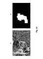
- FIG. 2Aillustrates an example image 200 and a corresponding mask 202 .
- FIG. 2Billustrates another example image 204 and a corresponding mask 206 .
- the masks 202 and 206indicate (in white) which sections of the image are roof areas and indicate (in black) which sections of the image are non-roof areas.
- FIGS. 2C and 2Dillustrate sampling techniques used during the determination of image measures.
- each of the historical imagesis processed by determining, for each pixel in the image, one or more measures within a moving (N ⁇ M) sampling window about the pixel.
- N ⁇ Mmoving
- FIG. 2Cillustrates an image 210 overlaid with yellow and black rectangles, each of the yellow rectangles representing that some part of the enclosed section is a non-roof area of the image 210 , and each of the black rectangles representing that the entire section is a roof area of the image 210 .
- the transition zones between yellow and black rectanglestherefore, identify roof boundaries.
- FIGS. 2Dillustrates various other example images overlaid with rectangles indicating roof and non-roof areas.
- the roof and non-roof areasare determined with respect to roof masks, such as those described with reference to FIGS. 2A and 2B , above.
- the systemrecords the determined measures in association with whether the pixel was located in a roof or non-roof area, as determined, for example, with reference to the identified roof and non-roof areas of FIGS. 2C and 2D .
- FIG. 2Eillustrates data sources and process sampling employed in a second embodiment trained on data from the target image.
- the second embodimentis not trained on multiple historical images. Instead, the second embodiment is trained on an operator-specified region of interest within the target image.
- FIG. 2Eillustrates an image 220 and circles 224 and 226 .
- the circles 224 and 226are direct-manipulation controls that can be adjusted (e.g., dragged, sized) by an operator (user) to specify a region of interest.
- the operatorhas specified two regions of the roof by way of circles 224 and 226 .
- a lesser or greater number of and shapes of portions of the roofmay be specified as regions of interest.
- the region of interestneed not be limited to a roof. For example, by selecting a portion of the driveway, the operator can cause the system to automatically determine the likely outline of the driveway, for use in generating a paving estimate report or other purpose.
- FIG. 2Fillustrates example image measures (features) used during training.
- the image measurescan be broadly classified into localized measures and neighborhood measures.
- Localized measuresdescribe image textural characteristics at a particular processing point (e.g., a pixel at the center of one of the N ⁇ M sampling windows described above).
- Example localized measuresmay include surface fractal analysis, wavelet coefficients, and topological contour complexity variation (TCCV).
- Neighborhood measuresinclude ranging related neighborhood measures that describe the organization of structure surrounding a particular processing point.
- Example neighborhood measuresinclude radial complexity and radial organization variation.
- FIG. 2Fdepicts neural networks 230 a - 230 e that are trained based on image measures or separable descriptor groups derived from image measures determined as described above for either the first or second embodiment.
- Each of the neural networks 230 a - 230 eis a full associative n-connected back-propagation neural network.
- Neural networks 230 a - 230 eare respectively trained either on direct measures (such as a surface fractal analysis measure, a wavelet coefficient measure, a topological contour complexity variation (TCCV) measure, a radial complexity measure, and a radial organization variation measure) or on separable descriptor groups (clusters) derived from statistical analysis of the aforementioned measures, as described with respect to FIGS. 2G-2L , below.
- direct measuressuch as a surface fractal analysis measure, a wavelet coefficient measure, a topological contour complexity variation (TCCV) measure, a radial complexity measure, and a radial organization variation measure
- clustersseparable descriptor groups
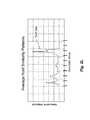
- FIG. 2Sis a graph of the learning curve exhibited by an example neural network used in the first embodiment.
- the graphplots training iteration (x-axis) against normalized error (y-axis).
- FIGS. 2G-2Iillustrate the process of determining group descriptor patterns that are used to identify roof or non-roof areas of an image.
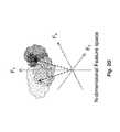
- Group descriptor patternsare determined in the following manner. First, image measures are taken for training data (either historical images or from the operator-specified region of interest). Those image measures can be represented as a “cloud” in an n-dimensional feature space, as shown in FIG. 2G , where the value of each pixel (or other processing unit) is a vector comprising the values determined for each of the measures calculated for that pixel.
- a feature transformationis performed, wherein image measures are statistically analyzed using clustering techniques to group the data into separable descriptor groups (clusters), as shown in FIG. 2H .
- the number of descriptor groupsis not necessarily the same as the number of measures. For example, if five measures are used (as shown in FIG. 2F ), a smaller number (e.g., three) descriptor groups may be determined.
- the descriptor groupstogether form a new feature vector that includes any error and uncertainty (e.g., due to changing image quality) of the measurements folded into a space describing the average statistical value at a roof (or non-roof) point.
- each descriptor groupis compared to each other descriptor group, using a statistical model such as an associative neural network, to create a group descriptor pattern of inter-relational characteristics.
- group descriptor patternsserve as the basis for identifying image features, such as roofs, non-roofs, vegetation, cement patios not covered, decks, or the like.
- a deckwhich is adjacent a home and not covered by a roof, can also be identified as not part of the roof.
- FIGS. 2J-2Lillustrate generation of average group descriptor patterns from multiple group descriptor patterns.
- An average group descriptor patterncan serve as a fingerprint that can be associated with particular features in the image, such as roofs, non-roofs, vegetation, pavement, decks, or the like.
- FIGS. 2J and 2Killustrate the generation of average group descriptor patterns in the first embodiment. In the first embodiment, average group descriptor patterns are generated as follows.
- FIG. 2Jshows example roof like and non-roof like patterns in the first embodiment.
- FIG. 2Kshows another example of roof like (in red) and non-roof like (in blue) patterns in a graph of descriptor group versus associative amplitude.
- the examples of FIGS. 2J and 2Kshow that particular descriptor groups are more highly associated with roofs (or non-roofs) than other descriptor groups.
- average group descriptor patternsare generated as follows. For all the points under the operator specified regions of interest (typically a portion of the roof) in the target image, measures within the regions of interest are analyzed and an average group descriptor pattern is generated and cross correlated using an associative neural network, creating a single roof like pattern template that may be used to determine which regions of an image are likely to be roof areas.
- the trained neural networksdescribe the average descriptor pattern for a roof of the type specified within the operator specified regions of interest in the target image.
- FIGS. 2M-2Pillustrate roof detection in a first embodiment trained on historical data.
- a roof in a target imageis detected based on the above-described training as follows. For every point across the target image, the probability of a point being on the roof is is generated by comparing the measured descriptor group pattern at each point to the average trained/learned pattern for the historical response. This probability intensity value is weighted by assessing how much it is similar to a roof and how much it is similar to the learned non-roof pattern.
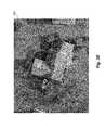
- Image 250 of FIG. 2Mrepresents (in terms of brightness) the likelihood that a point of image 200 ( FIG. 2A ) is on the roof.
- the image itselfis very fuzzy, but one factor in this step is the brightness of the respective pixel, not the sharpness of a boundary for a group of pixels
- the target imageis segmented using a watershed technique that separates the target image into segments based on boundary gradient amplitudes.
- the segmentsare determined based on contrast differences within the target image.
- Image 252 of FIG. 2Mrepresents the watershed segmentation performed upon image 200 ( FIG. 2A ).
- each watershed segmentis overlaid on top of the probability mapping and the total average probability that the segment is roof like is computed. If the calculated probability passes acceptable amplitude criteria, the watershed segment is defined as being part of the roof.
- Image 260 of FIG. 2Nshows the watershed segments overlaid on top of the probability mapping shown in image 250 ( FIG. 2M ).
- Image 262 of FIG. 2Nshows the determined roof segments overlaid on top of the original target image 200 .
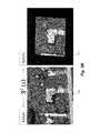
- FIG. 2Oshows another view of automatic roof detection performed by the first embodiment.
- FIG. 2Oshows a side-by-side view of a mask 270 and image 272 .
- Mask 270represents the automatically detected roof.
- Image 272depicts the mask 270 representing the automatically detected roof overlaid on top of image 200 .
- FIG. 2Pshows another view of automatic roof detection performed by the first embodiment.
- FIG. 2Pshows a mask 280 generated from the result of a probability mapping performed with reference to a trained AI system.
- FIG. 2Pfurther shows an image 282 comprising the original image 200 overlaid with the watershed segmentation (red lines) and filled with white according to whether the segments sufficiently intersect the mask 280 .
- FIG. 2Palso shows a mask 284 detailing the watershed segments bounded by the roof mask 280 .
- the mask 284can serve as a wire frame representation of the detected roof.
- FIG. 2Tshows another view of automatic roof detection performed by the first embodiment.
- FIG. 2Tshows a side-by-side view of the roof selected with the assistance of an associative neural network (left) and the original image (right).
- FIGS. 2Q-2Rillustrate roof detection in a second embodiment trained on data from the target image.
- a roof in a target imageis detected based on the above-described training as follows.
- the target imageis segmented using a modified Edison (edge detection and image segmentation) mean shift based/synergistic segmentation procedure to break an image into regions based on textural content, similarity, size and local association.
- FIG. 2Qshows an image 290 representing pre-segmentation of the target image 220 ( FIG. 2E ).
- Image 292 of FIG. 2Rrepresents the similarity probability of the segments shown in image 290 , with the green-colored segments being highly similar to the regions of interest, and the red-colored segments being dissimilar to the regions of interest.
- Image 294 of FIG. 2Rrepresents the end result of automatic roof detection performed by the second embodiment.
- the color blueindicates detected roof segments
- the color greenindicates non-roof segments.
- embodimentsneed not use the specific segmentation techniques described above.
- the first embodimentcould instead use the Edison-style segmentation described with respect to the second embodiment.
- Other segmentation, edge-, or region-detection techniquesmay be similarly employed.
- the region of interestneed not be on the target image itself. Instead, the region of interest could be on another image that is similar in some way to the target image.
- multiple target imagesare automatically grouped based on image characteristics (e.g., average contrast, brightness, color-histogram, or the like). Then, for each of these groups, an exemplar image is selected (e.g., by random, by the operator, or the like) and used by the operator to specify a region of interest to use for training purposes.
- the AI systemis trained on the region of interest from the exemplar image. Then, for each of the images in the group, a roof is detected based on the trained AI system.
- the AI systemwill be automatically configured to identify image areas that are similar to the specified region. For example, by specifying an area of lawn as a region of interest, sections of lawn could be detected for purposes of estimating a quantity of sod required to cover a particular property.
- such techniquescan be used to automatically measure ground coverage over urban or suburban areas, so as to track the growth or decline of vegetation (e.g., tree) coverage, non-permeable surface (e.g., pavement) coverage, and the like.
- the goal of computer driven image registrationis to correlate information contained in multiple viewpoints of a structure. This correlation results in the construction of a 3D volume consistent with the viewpoints provided by the individual images.
- the computer programsthus provide an automated image registration, namely, without the use of human skill and judgment to create the results.
- FIG. 3Adepicts a virtual volume resulting from automated image registration applied to a set of 2D photographs (images) of the same object.
- the imagesinclude an overhead view and one or more perspective views.
- Automated image registrationincludes minimizing an error (cost) function associated with a projection of one image into a second image. Reduction of this error function establishes the change in the observer's viewpoint around a virtual 3D space that produced the two viewpoints seen in the images.
- the processdetermines transform parameters using non-linear least-squares optimization.
- the processuses the sum of squared differences (SSD) as the objective criterion that defines similarity measure between 2 images, normalized 0-1.0, as defined in the following:
- the processuses a model defined as:
- ⁇ 2 (a)⁇ [I 1 (u i ) ⁇ I 2 ′ (u i )] 2
- Tbeing a geometric transform applied on an overhead image I 2 to map its [x,y] coordinate system to the [u,v] coordinate system of a prospective N,S,E,W I 1 view.
- FIG. 3Bshows example images 310 and 312 . Images 310 and 312 are taken from different orientations. The automated registration process seeks to map (project) image 310 onto 312 .
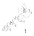
- FIG. 3Cillustrates an iterative approach to mapping one image 320 onto another image 322 , and determining the change in the associated error function, represented as image 324 .
- FIG. 3Dillustrates the seven degrees of freedom that are iterated over when searching for a reduced or minimal value of the error function.
- the seven degrees of freedominclude translation in three dimensions (Tx, Ty, Tz), rotation (Rx, Ry, and Rz), and scale (Sc).
- FIGS. 3E and 3Fillustrate a process for iterating over the seven degrees of freedom.
- FIG. 3Gshows a graph 350 and images 352 and 354 .
- the graph 350depicts a three dimensional slice of the seven dimensional (7D) error function space depicting the minima in the error functions. The values have been inverted to show the minima as a peak rather than a valley.
- Images 352 and 354are each an overhead image (red channel) with an oblique image (blue channel) overlaid. Image 352 represents the initial conditions. Image 354 represents an improved fit resulting from a reduction of the SSD error function.
- FIG. 3Hdepicts the convergence of the SSD function by way of a reduction of the error function.
- FIG. 3Iincludes an image 360 that represents example initial conditions.
- image 360represents an overhead image (red channel) with a mapped oblique image (blue channel) overlaid.
- FIG. 3Jillustrates results of the automated registration process after a coarse a sampling of the 7D error function space to determine a reduced value or an approximate minimum of the SSD function.
- image 362represents an overhead image (red channel) with a mapped oblique image (blue channel) overlaid.
- Graph 363represents the coarse sampling of the 7D error function space, with an approximate minimum shown (again using inverted values).
- FIG. 3Killustrates results after finer sampling of the 7D error function space to determine a minima or a reduced value of the SSD function.
- a surfacewas fit to the SSD function surface to determine a better estimate of the reduced value or minima.
- a finer sampling of the 7D error function space in the vicinity of the approximate minima discussed in FIG. 3Jcould be made to directly compute a more accurate location of the minima.
- Image 364represents an overhead image (red channel) with a mapped oblique image (blue channel) overlaid.
- Graph 365represents the coarse sampling of the 7D error function space, with an approximate minimum shown (again using inverted values).
- FIG. 4is an example block diagram of a computing system for practicing embodiments of a roof estimation system.
- FIG. 4shows a computing system 400 that may be utilized to implement the Roof Estimation System (“RES”) 100 .
- RESRoof Estimation System
- One or more general purpose or special purpose computing systemsmay be used to implement the Roof Estimation System 100 .
- the computing system 400may comprise one or more distinct computing systems present at distributed locations.
- each block shownmay represent one or more such blocks as appropriate to a specific embodiment or may be combined with other blocks.
- the various blocks of the Roof Estimation System 100may physically reside on one or more machines, which use standard inter-process communication mechanisms (e.g., TCP/IP) to communicate with each other.
- the Roof Estimation System 100may be implemented in software, hardware, firmware, or in some combination to achieve the capabilities described herein.
- computing system 400comprises a computer memory (“memory”) 401 , a display 402 , one or more Central Processing Units (“CPU”) 403 , Input/Output devices 404 (e.g., keyboard, mouse, joystick, track pad, CRT or LCD display, and the like), other computer-readable media 405 , and network connections 406 .
- the Roof Estimation System 100is shown residing in memory 401 . In other embodiments, some portion of the contents, some of, or all of the components of the Roof Estimation System 100 may be stored on and/or transmitted over the other computer-readable media 405 .
- the components of the Roof Estimation System 100preferably execute on one or more CPUs 403 and generate roof estimate reports, as described herein.
- Other code or programs 440e.g., a Web server, a database management system, and the like
- data repositoriessuch as data repository 420
- Other code or programs 440also reside in the memory 401 , and preferably execute on one or more CPUs 403 . Not all of the components in FIG. 4 are required for each implementation. For example, some embodiments embedded in other software do not provide means for user input, for display, for a customer computing system, or other components.
- the Roof Estimation System 100includes an image acquisition engine 101 , a roof modeling engine 102 , a report generation engine 103 , an interface engine 414 , and a roof estimation system data repository 416 . Other and/or different modules may be implemented.
- the Roof Estimation System 100interacts via a communication system 450 with an image source computing system 465 , an operator computing system 475 , and/or a customer computing system 470 .
- Communication system 450may utilize one or more protocols to communicate via one or more physical networks, including local area networks, wireless networks, dedicated lines, internets, the Internet, and the like.
- the image acquisition engine 101performs at least some of the functions described with respect to FIG. 1 , above.
- the image acquisition engine 101interacts with the image source computing system 465 to obtain one or more images of a building, and stores those images in the Roof Estimation System data repository 416 for processing by other components of the Roof Estimation System 100 .
- the image acquisition engine 101may perform one or more pre-processing techniques used for automatic roof detections, such as watershed or Edison-style segmentation of images.
- the roof modeling engine 102performs at least some of the functions described with reference to FIG. 1 , above.
- the roof modeling engine 102generates a model based on one or more images of a building that are obtained from the Roof Estimation System data repository 416 or directly from the image source computing system 465 .
- model generationmay be performed semi-automatically, based on at least some inputs received from the operator computing system 475 .
- the roof modeling engine 102can automatically detect a roof in a target image of a building, based on an AI system trained on historical image data and/or a region of interest specified in the target image.
- the AI systemmay be implemented as part of the roof modeling engine 102 or some module.
- the AI systemmay also include one or more decision-support modules, such as associative neural networks, Bayesian networks, Hidden Markov Models, and the like.
- the roof modeling engine 102may also be configured to automatically register images. These automated and semi-automated techniques are further described with respect to FIGS. 2 and 3 , above. After the roof modeling engine 102 generates a model, it stores the generated model in the Roof Estimation System data repository 416 for further processing by other components of the Roof Estimation System 100 .
- the report generation engine 103performs at least some of the functions described with reference to FIG. 1 , above.
- the report generation engine 103generates roof reports based on models stored in the Roof Estimation System data repository 416 .
- Generating a roof reportmay include preparing one or more views of a given 3D model of a roof, annotating those views with indications of various characteristics of the model, such as dimensions of sections or other features (e.g., ridges, valleys, etc.) of the roof, slopes of sections of the roof, areas of sections of the roof, etc.
- the report generation engine 103facilitates transmission of roof measurement information that may or may not be incorporated into a roof estimate report.
- the roof generation engine 103may transmit roof measurement information based on, or derived from, models stored in the Roof Estimation System data repository 416 .
- roof measurement informationmay be provided to, for example, third-party systems that generate roof estimate reports based on the provided information.
- the interface engine 414provides a view and a controller that facilitate user interaction with the Roof Estimation System 100 and its various components.
- the interface engine 414may implement a user interface engine 104 described with reference to FIG. 1 .
- the user interface engine 104may provide an interactive graphical user interface that can be used by a human user operating the operator computing system 475 to interact with, for example, the roof modeling engine 102 , to perform functions such as specifying regions of interest for automated roof detection.
- access to the functionality of the interface engine 414is provided via a Web server, possibly executing as one of the other programs 440 .
- the interface engine 414provides programmatic access to one or more functions of the Roof Estimation System 100 .
- the interface engine 414provides a programmatic interface (e.g., as a Web service, static or dynamic library, etc.) to one or more roof estimation functions of the Roof Estimation System 100 that may be invoked by one of the other programs 440 or some other module.
- the interface engine 414facilitates the development of third-party software, such as user interfaces, plug-ins, adapters (e.g., for integrating functions of the Roof Estimation System 100 into desktop applications, Web-based applications, embedded applications, etc.), and the like.
- the interface engine 414may be in at least some embodiments invoked or otherwise accessed via remote entities, such as the operator computing system 475 , the image source computing system 465 , and/or the customer computing system 470 , to access various roof estimation functionality of the Roof Estimation System 100 .
- the Roof Estimation System data repository 416stores information related the roof estimation functions performed by the Roof Estimation System 100 . Such information may include image data 105 , model data 106 , and/or report data 107 described with reference to FIG. 1 . Furthermore, the data repository 416 may include information related to automatic roof detection and/or image registration. Such information includes historical image data, representations of trained AI system, and the like. In addition, the Roof Estimation System data repository 416 may include information about customers, operators, or other individuals or entities associated with the Roof Estimation System 100 .
- components/modules of the Roof Estimation System 100are implemented using standard programming techniques.
- the Roof Estimation System 100may be implemented as a “native” executable running on the CPU 403 , along with one or more static or dynamic libraries.
- the Roof Estimation System 100is implemented as instructions processed by a virtual machine that executes as one of the other programs 440 .
- a range of programming languages known in the artmay be employed for implementing such example embodiments, including representative implementations of various programming language paradigms, including but not limited to, object-oriented (e.g., Java, C++, C#, Matlab, Visual Basic.NET, Smalltalk, and the like), functional (e.g., ML, Lisp, Scheme, and the like), procedural (e.g., C, Pascal, Ada, Modula, and the like), scripting (e.g., Perl, Ruby, Python, JavaScript, VBScript, and the like), declarative (e.g., SQL, Prolog, and the like).
- object-orientede.g., Java, C++, C#, Matlab, Visual Basic.NET, Smalltalk, and the like
- functionale.g., ML, Lisp, Scheme, and the like
- procedurale.g., C, Pascal, Ada, Modula, and the like
- scriptinge.g., Perl, Ruby, Python, JavaScript,
- the embodiments described abovemay also use well-known synchronous or asynchronous client-server computing techniques.
- the various componentsmay be implemented using more monolithic programming techniques as well, for example, as an executable running on a single CPU computer system, or alternatively decomposed using a variety of structuring techniques known in the art, including but not limited to, multiprogramming, multithreading, client-server, or peer-to-peer, running on one or more computer systems each having one or more CPUs.
- Some embodimentsexecute concurrently and asynchronously, and communicate using message passing techniques.
- Equivalent synchronous embodimentsare also supported by an Roof Estimation System implementation.
- other functionscould be implemented and/or performed by each component/module, and in different orders, and by different components/modules, yet still achieve the functions of the RES.
- programming interfaces to the data stored as part of the Roof Estimation System 100can be available by standard mechanisms such as through C, C++, C#, and Java APIs; libraries for accessing files, databases, or other data repositories; through scripting languages such as XML; or through Web servers, FTP servers, or other types of servers providing access to stored data.
- the Roof Estimation System data repository 416may be implemented as one or more database systems, file systems, memory buffers, or any other technique for storing such information, or any combination of the above, including implementations using distributed computing techniques.
- the example Roof Estimation System 100can be implemented in a distributed environment comprising multiple, even heterogeneous, computer systems and networks.
- the image acquisition engine 101 , the roof modeling engine 102 , the report generation engine 103 , the interface engine 414 , and the data repository 416are all located in physically different computer systems.
- various modules of the Roof Estimation System 100are hosted each on a separate server machine and are remotely located from the tables which are stored in the data repository 416 .
- one or more of the modulesmay themselves be distributed, pooled or otherwise grouped, such as for load balancing, reliability or security reasons. Different configurations and locations of programs and data are contemplated for use with techniques of described herein.
- a variety of distributed computing techniquesare appropriate for implementing the components of the illustrated embodiments in a distributed manner including but not limited to TCP/IP sockets, RPC, RMI, HTTP, Web Services (XML-RPC, JAX-RPC, SOAP, and the like).
- some or all of the components of the Roof Estimation Systemare implemented or provided in other manners, such as at least partially in firmware and/or hardware, including, but not limited to one or more application-specific integrated circuits (ASICs), standard integrated circuits, controllers (e.g., by executing appropriate instructions, and including microcontrollers and/or embedded controllers), field-programmable gate arrays (FPGAs), complex programmable logic devices (CPLDs), and the like
- ASICsapplication-specific integrated circuits
- controllerse.g., by executing appropriate instructions, and including microcontrollers and/or embedded controllers
- FPGAsfield-programmable gate arrays
- CPLDscomplex programmable logic devices
- Some or all of the system components and/or data structuresmay also be stored (e.g., as software instructions or structured data) on a computer-readable medium, such as a hard disk, a memory, a network, or a portable media article to be read by an appropriate drive or via an appropriate connection.
- the system components and data structuresmay also be stored as data signals (e.g., by being encoded as part of a carrier wave or included as part of an analog or digital propagated signal) on a variety of computer-readable transmission mediums, which are then transmitted, including across wireless-based and wired/cable-based mediums, and may take a variety of forms (e.g., as part of a single or multiplexed analog signal, or as multiple discrete digital packets or frames).
- Such computer program productsmay also take other forms in other embodiments. Accordingly, embodiments of this disclosure may be practiced with other computer system configurations.
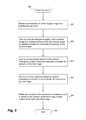
- FIG. 5is an example flow diagram of roof detection routine provided by an example embodiment.
- the illustrated routine 500may be provided by, for example, execution of the roof estimation system 100 described with respect to FIG. 4 .
- the illustrated routine 500detects a roof in an image of a building.
- the routinebegins in step 501 , where it receives an indication of a first (target) image of a building having a roof.
- the target imageis the image in which a roof is to be detected.
- the routinetrains an artificial intelligence system with a second image of a building having a roof, the training based on statistical measures computed for sections of the second image.
- Image sectionsmay be individual pixels or regions of pixels.
- the training results in the artificial intelligence systembeing configured to indicate whether a roof is shown in a section of an image.
- training the artificial intelligence systemincludes training an associative network using historical image data that includes both multiple images and indications of which sections of the multiple images are roof areas.
- the first and second imagesare the same image
- training the artificial intelligence systemincludes training an associative network upon an operator-specified region of interest.
- multiple associative networksmay be trained against various statistical measures.
- different types of associative networksmay be utilized, including neural networks, Bayesian networks, and the like.
- step 502is performed previously and is not part of the inventive method of identifying a roof.
- An associative network, artificial intelligence system and/or data arrangement, or other computer systemis separately created and the training is completed thereon prior to the execution of the process 500 .
- the step 502therefore does not form part of the invention and is not one of the invention steps in this embodiment. Rather, the image is received at 501 and, having been input to the associative network at 503 , the network performs the statistical analysis and outputs in 504 indications of the roof and an outline of the roof. Thus, this method of the invention does not include 502 .
- step 503the routine inputs to an associative network of the artificial intelligence system statistical measures computed for sections of the first image.
- Example statistical measuresare described with respect to FIG. 2F , above.
- the routinereceives from the artificial intelligence system indications of whether a roof is shown the sections of the first image.
- These indicationsmay be likelihoods (probabilities) or some other measure, such as a degree of association of features measured in each image section with roof or non-roof areas of the training data.
- the routinedetermines, based on the indications of whether a roof is shown in the sections of the first image, a likely outline of the roof in the first image. Determining the roof outline may be performed in various ways. In one embodiment, the routine determines watershed segments for the first image, based on boundary gradient amplitudes. Then, for each watershed segment, the routine determines, based on the output of the associative network within the artificial intelligence system, a likelihood that the watershed segment includes a roof. The routine then uses the determined likelihoods to decide whether to retain or discard watershed segments as part of the detected roof.
- determining the roof outlineincludes determining Edison segments of the first image, such that the pixels of each of the Edison segments have similar textural content. Then, for each of the Edison segments, the routine determines, based on the output of the associative network within the artificial intelligence system, whether the Edison segment is similar to an operator-specified region of interest, and if so, includes the Edison segment in the outline of the detected roof.
- the routineends.
- the routinereturns to one of the above steps to perform additional processing, such as to detect building roofs in other images.
- additional processingsuch as to detect building roofs in other images.
- Other functionsmay also be performed.
- the routine 500may generate a roof estimate report based at least in part on the determined likely outline of the roof in the target image.
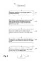
- FIG. 6is an example flow diagram of another roof detection routine provided by an example embodiment.
- the illustrated routine 600may be provided by, for example, execution of the roof estimation system 100 described with respect to FIG. 4 .
- the illustrated routine 600detects a roof in an image of a building.
- the routinebegins in step 601 , where it receives an indication of a first (target) image of a building having a roof.
- the routinetrains multiple neural networks with historical image data, the training based on statistical measures computed for sections of images included in the historical image data. The training results in the multiple neural networks being configured to discriminate between roof and non-roof sections of an image.
- the routineinputs to the multiple neural networks statistical measures computed for sections of the target image. Step 602 can be omitted and the inventive steps carried out going from 601 to 603 .
- the routinereceives from the multiple neural networks indications of whether a roof is shown in the sections of the target image.
- the routinedetermines, based on the indications of whether a roof is shown in the sections of the target image, a likely outline of the roof in the target image. After step 605 , the routine ends.
- routine 600returns to one of the above steps to perform additional processing, such as to detect building roofs in other images. Other functions may also be performed. For example, after step 605 , the routine 600 may store the determined likely outline of the roof, such that the outline can be used to generate a roof estimate report or the like.
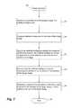
- FIG. 7is an example flow diagram of a further roof detection routine provided by an example embodiment.
- the illustrated routine 700may be provided by, for example, execution of the roof estimation system 100 described with respect to FIG. 4 .
- the illustrated routine 700detects a roof in an image of a building.
- the routinebegins in step 701 , where it receives an indication of a first (target) image of a building having a roof.
- the routinecomputes statistical measures for sections of the target image.
- the routineinputs to an artificial intelligence system the computed statistical measures, the associative network configured to indicate whether a roof is shown in a section of an image.
- the routinereceives from the artificial intelligence system indications of whether a roof is shown in the sections of the target image.
- the routinedetermines, based on the indications of whether a roof is shown in the sections of the target image, a likely outline of the roof in the target image. After step 705 , the routine ends. In other embodiments, the routine returns to one of the above steps to perform additional processing, such as to detect building roofs in other images.
- the methods, systems, and techniques for generating and providing roof estimate reports discussed hereinare applicable to other architectures other than the illustrated architecture or a particular roof estimation system implementation.
- the methods and systems discussed hereinare applicable to differing network protocols, communication media (optical, wireless, cable, etc.) and devices (such as wireless handsets, electronic organizers, personal digital assistants, portable email machines, game machines, pagers, navigation devices such as GPS receivers, etc.).
- the methods and systems discussed hereinmay be utilized by and/or applied to other contexts or purposes, such as by or for solar panel installers, roof gutter installers, awning companies, HVAC contractors, general contractors, and/or insurance companies.
Landscapes
- Engineering & Computer Science (AREA)
- Theoretical Computer Science (AREA)
- Physics & Mathematics (AREA)
- General Physics & Mathematics (AREA)
- Multimedia (AREA)
- Computer Vision & Pattern Recognition (AREA)
- Artificial Intelligence (AREA)
- Evolutionary Computation (AREA)
- Computing Systems (AREA)
- Health & Medical Sciences (AREA)
- Data Mining & Analysis (AREA)
- Databases & Information Systems (AREA)
- General Health & Medical Sciences (AREA)
- Medical Informatics (AREA)
- Software Systems (AREA)
- Bioinformatics & Cheminformatics (AREA)
- Bioinformatics & Computational Biology (AREA)
- Evolutionary Biology (AREA)
- Life Sciences & Earth Sciences (AREA)
- General Engineering & Computer Science (AREA)
- Image Analysis (AREA)
Abstract
Description
- =Σ[I1(ui)−TA{I2(xi)}]2
Claims (20)
Priority Applications (1)
| Application Number | Priority Date | Filing Date | Title |
|---|---|---|---|
| US14/328,266US8995757B1 (en) | 2008-10-31 | 2014-07-10 | Automated roof identification systems and methods |
Applications Claiming Priority (4)
| Application Number | Priority Date | Filing Date | Title |
|---|---|---|---|
| US19789508P | 2008-10-31 | 2008-10-31 | |
| US12/590,131US8731234B1 (en) | 2008-10-31 | 2009-11-02 | Automated roof identification systems and methods |
| US14/086,885US9070018B1 (en) | 2008-10-31 | 2013-11-21 | Automated roof identification systems and methods |
| US14/328,266US8995757B1 (en) | 2008-10-31 | 2014-07-10 | Automated roof identification systems and methods |
Related Parent Applications (1)
| Application Number | Title | Priority Date | Filing Date |
|---|---|---|---|
| US14/086,885ContinuationUS9070018B1 (en) | 2008-10-31 | 2013-11-21 | Automated roof identification systems and methods |
Publications (1)
| Publication Number | Publication Date |
|---|---|
| US8995757B1true US8995757B1 (en) | 2015-03-31 |
Family
ID=52707931
Family Applications (3)
| Application Number | Title | Priority Date | Filing Date |
|---|---|---|---|
| US12/590,131Active2032-11-20US8731234B1 (en) | 2008-10-31 | 2009-11-02 | Automated roof identification systems and methods |
| US14/086,885Active2030-02-13US9070018B1 (en) | 2008-10-31 | 2013-11-21 | Automated roof identification systems and methods |
| US14/328,266ActiveUS8995757B1 (en) | 2008-10-31 | 2014-07-10 | Automated roof identification systems and methods |
Family Applications Before (2)
| Application Number | Title | Priority Date | Filing Date |
|---|---|---|---|
| US12/590,131Active2032-11-20US8731234B1 (en) | 2008-10-31 | 2009-11-02 | Automated roof identification systems and methods |
| US14/086,885Active2030-02-13US9070018B1 (en) | 2008-10-31 | 2013-11-21 | Automated roof identification systems and methods |
Country Status (1)
| Country | Link |
|---|---|
| US (3) | US8731234B1 (en) |
Cited By (26)
| Publication number | Priority date | Publication date | Assignee | Title |
|---|---|---|---|---|
| US20150302529A1 (en)* | 2014-04-18 | 2015-10-22 | Marshall & Swift/Boeckh, LLC | Roof condition evaluation and risk scoring system and method |
| US9501700B2 (en) | 2012-02-15 | 2016-11-22 | Xactware Solutions, Inc. | System and method for construction estimation using aerial images |
| US9679227B2 (en) | 2013-08-02 | 2017-06-13 | Xactware Solutions, Inc. | System and method for detecting features in aerial images using disparity mapping and segmentation techniques |
| US9846915B2 (en) | 2016-03-17 | 2017-12-19 | Conduent Business Services, Llc | Image capture system for property damage assessment |
| US9870609B2 (en) | 2016-06-03 | 2018-01-16 | Conduent Business Services, Llc | System and method for assessing usability of captured images |
| US9886774B2 (en) | 2014-10-22 | 2018-02-06 | Pointivo, Inc. | Photogrammetric methods and devices related thereto |
| US10511676B2 (en) | 2016-03-17 | 2019-12-17 | Conduent Business Services, Llc | Image analysis system for property damage assessment and verification |
| US10529029B2 (en) | 2016-09-23 | 2020-01-07 | Aon Benfield Inc. | Platform, systems, and methods for identifying property characteristics and property feature maintenance through aerial imagery analysis |
| US10650285B1 (en) | 2016-09-23 | 2020-05-12 | Aon Benfield Inc. | Platform, systems, and methods for identifying property characteristics and property feature conditions through aerial imagery analysis |
| US11055786B2 (en) | 2016-06-03 | 2021-07-06 | Conduent Business Services, Llc | Image segmentation system for verification of property roof damage |
| US11094113B2 (en) | 2019-12-04 | 2021-08-17 | Geomni, Inc. | Systems and methods for modeling structures using point clouds derived from stereoscopic image pairs |
| US11120505B2 (en) | 2016-06-03 | 2021-09-14 | Conduent Business Services, Llc | Image analysis system for verification of property roof damage |
| US11151378B2 (en) | 2015-08-31 | 2021-10-19 | Cape Analytics, Inc. | Systems and methods for analyzing remote sensing imagery |
| US11200353B2 (en) | 2018-12-21 | 2021-12-14 | Geospan Corporation | Geographic information system for creating 3D structure models using perspective view drafting |
| US11222426B2 (en) | 2020-06-02 | 2022-01-11 | Cape Analytics, Inc. | Method for property feature segmentation |
| US11232150B2 (en) | 2020-04-10 | 2022-01-25 | Cape Analytics, Inc. | System and method for geocoding |
| US20220028016A1 (en)* | 2014-04-10 | 2022-01-27 | Vivint Solar, Inc. | Photovoltaic system installation |
| US11367265B2 (en) | 2020-10-15 | 2022-06-21 | Cape Analytics, Inc. | Method and system for automated debris detection |
| US11397867B2 (en) | 2019-09-23 | 2022-07-26 | Stephen C. Martin | Architectural database tag assembly and method for installing architectural database tag assembly |
| US20230296365A1 (en)* | 2022-03-15 | 2023-09-21 | Metal-Era, Llc | System of measuring objects in an environment |
| US11861843B2 (en) | 2022-01-19 | 2024-01-02 | Cape Analytics, Inc. | System and method for object analysis |
| US11875413B2 (en) | 2021-07-06 | 2024-01-16 | Cape Analytics, Inc. | System and method for property condition analysis |
| US11967097B2 (en) | 2021-12-16 | 2024-04-23 | Cape Analytics, Inc. | System and method for change analysis |
| US12050994B2 (en) | 2018-11-14 | 2024-07-30 | Cape Analytics, Inc. | Systems, methods, and computer readable media for predictive analytics and change detection from remotely sensed imagery |
| US12229845B2 (en) | 2022-06-13 | 2025-02-18 | Cape Analytics, Inc. | System and method for property group analysis |
| US12333788B2 (en) | 2022-01-24 | 2025-06-17 | Cape Analytics, Inc. | System and method for subjective property parameter determination |
Families Citing this family (41)
| Publication number | Priority date | Publication date | Assignee | Title |
|---|---|---|---|---|
| US8977520B2 (en)* | 2010-10-21 | 2015-03-10 | Pictometry International Corp. | Computer system for automatically classifying roof elements |
| CA2841423A1 (en)* | 2011-06-12 | 2012-12-20 | James G. BIGGAR | Energy systems |
| US9002719B2 (en) | 2012-10-08 | 2015-04-07 | State Farm Mutual Automobile Insurance Company | Device and method for building claim assessment |
| US10332138B1 (en)* | 2013-02-05 | 2019-06-25 | Zillow, Inc. | Estimating the cost of residential remodeling projects |
| US8818572B1 (en) | 2013-03-15 | 2014-08-26 | State Farm Mutual Automobile Insurance Company | System and method for controlling a remote aerial device for up-close inspection |
| US8872818B2 (en) | 2013-03-15 | 2014-10-28 | State Farm Mutual Automobile Insurance Company | Methods and systems for capturing the condition of a physical structure |
| US9082015B2 (en)* | 2013-03-15 | 2015-07-14 | State Farm Mutual Automobile Insurance Company | Automatic building assessment |
| US9286539B2 (en)* | 2014-02-11 | 2016-03-15 | Google Inc. | Constructing contours from imagery |
| US9846921B2 (en)* | 2014-09-29 | 2017-12-19 | The Boeing Company | Dynamic image masking system and method |
| US11093982B1 (en) | 2014-10-02 | 2021-08-17 | Zillow, Inc. | Determine regional rate of return on home improvements |
| US11634214B1 (en) | 2015-01-23 | 2023-04-25 | Liberty Mutual Insurance Company | Drones with sensors used in insurance applications |
| US11266056B2 (en)* | 2015-10-23 | 2022-03-08 | Deere & Company | System and method for residue detection and implement control |
| US10521865B1 (en) | 2015-12-11 | 2019-12-31 | State Farm Mutual Automobile Insurance Company | Structural characteristic extraction and insurance quote generation using 3D images |
| US10217207B2 (en) | 2016-01-20 | 2019-02-26 | Ez3D, Llc | System and method for structural inspection and construction estimation using an unmanned aerial vehicle |
| WO2017132636A1 (en)* | 2016-01-29 | 2017-08-03 | Pointivo, Inc. | Systems and methods for extracting information about objects from scene information |
| WO2017142788A1 (en)* | 2016-02-15 | 2017-08-24 | Pictometry International Corp. | Automated system and methodology for feature extraction |
| US11481968B2 (en)* | 2016-02-29 | 2022-10-25 | Accurence, Inc. | Systems and methods for improving property inspection efficiency |
| US10176527B1 (en) | 2016-04-27 | 2019-01-08 | State Farm Mutual Automobile Insurance Company | Providing shade for optical detection of structural features |
| US10867328B2 (en) | 2016-05-03 | 2020-12-15 | Yembo, Inc. | Systems and methods for providing AI-based cost estimates for services |
| CA3020714A1 (en) | 2016-05-03 | 2017-11-09 | Zachary Rattner | Systems and methods for providing ai-based cost estimates for services |
| US10032310B2 (en) | 2016-08-22 | 2018-07-24 | Pointivo, Inc. | Methods and systems for wireframes of a structure or element of interest and wireframes generated therefrom |
| US10127670B2 (en) | 2016-09-27 | 2018-11-13 | Xactware Solutions, Inc. | Computer vision systems and methods for detecting and modeling features of structures in images |
| US11043026B1 (en) | 2017-01-28 | 2021-06-22 | Pointivo, Inc. | Systems and methods for processing 2D/3D data for structures of interest in a scene and wireframes generated therefrom |
| US11481993B2 (en)* | 2017-09-11 | 2022-10-25 | Hover Inc. | Trained machine learning model for estimating structure feature measurements |
| US10861247B2 (en) | 2017-09-21 | 2020-12-08 | Nearmap Us, Inc. | Roof report generation |
| US10872534B2 (en)* | 2017-11-01 | 2020-12-22 | Kespry, Inc. | Aerial vehicle inspection path planning |
| CN108229364B (en)* | 2017-12-28 | 2022-02-25 | 百度在线网络技术(北京)有限公司 | Building contour generation method and device, computer equipment and storage medium |
| CA3030513A1 (en) | 2018-01-19 | 2019-07-19 | Sofdesk Inc. | Automated roof surface measurement from combined aerial lidar data and imagery |
| US10445401B2 (en) | 2018-02-08 | 2019-10-15 | Deep Labs Inc. | Systems and methods for converting discrete wavelets to tensor fields and using neural networks to process tensor fields |
| US11106911B1 (en)* | 2018-06-13 | 2021-08-31 | Pointivo, Inc. | Image acquisition planning systems and methods used to generate information for structures of interest |
| US10909757B2 (en) | 2018-06-15 | 2021-02-02 | Geomni, Inc. | Computer vision systems and methods for modeling roofs of structures using two-dimensional and partial three-dimensional data |
| US11308714B1 (en)* | 2018-08-23 | 2022-04-19 | Athenium Llc | Artificial intelligence system for identifying and assessing attributes of a property shown in aerial imagery |
| US11222464B2 (en) | 2019-08-22 | 2022-01-11 | The Travelers Indemnity Company | Intelligent imagery |
| CN110633553B (en)* | 2019-10-09 | 2023-07-18 | 郑豪 | Automatic generation method and system for residential floor plan |
| US11189032B2 (en) | 2020-04-01 | 2021-11-30 | Here Global B.V. | Method and apparatus for extracting a satellite image-based building footprint |
| WO2021226724A1 (en)* | 2020-05-14 | 2021-11-18 | Del Sol Arianna | System and computer-implemented method to analyze, predict or automate financial and operative management or any activities relating to buildings based on data about the same buildings |
| US20220092227A1 (en)* | 2020-09-22 | 2022-03-24 | Zillow, Inc. | Automated Identification And Use Of Building Floor Plan Information |
| CN112149585B (en)* | 2020-09-27 | 2024-12-10 | 上海商汤智能科技有限公司 | Image processing method, device, equipment and storage medium |
| US20230153931A1 (en)* | 2021-11-18 | 2023-05-18 | Cape Analytics, Inc. | System and method for property score determination |
| US11625511B1 (en) | 2021-11-19 | 2023-04-11 | Bmic Llc | Methods for designing, manufacturing, installing, and/or maintenance of roofing accessories and systems of use thereof |
| US12367696B2 (en)* | 2022-12-15 | 2025-07-22 | Idemia Public Security France | Systems and methods for document authentication |
Citations (81)
| Publication number | Priority date | Publication date | Assignee | Title |
|---|---|---|---|---|
| US5247356A (en) | 1992-02-14 | 1993-09-21 | Ciampa John A | Method and apparatus for mapping and measuring land |
| CA2191954A1 (en) | 1994-06-03 | 1995-12-14 | Wolfram Kirchner | Method for the collection, analysis, measurement and storage of geographical data |
| US5633995A (en) | 1991-06-19 | 1997-05-27 | Martin Marietta Corporation | Camera system and methods for extracting 3D model of viewed object |
| US5936628A (en)* | 1991-08-06 | 1999-08-10 | Canon Kabushiki Kaisha | Three-dimensional model processing method, and apparatus therefor |
| WO2000029806A2 (en) | 1998-11-06 | 2000-05-25 | Friedhelm Gante | Method for measuring the surfaces of a house roof |
| DE19857667A1 (en) | 1998-12-15 | 2000-08-17 | Aerowest Photogrammetrie H Ben | Process for creating a three-dimensional object description |
| US6323885B1 (en) | 1998-09-18 | 2001-11-27 | Steven Paul Wiese | Real estate value map computer system |
| US6333749B1 (en) | 1998-04-17 | 2001-12-25 | Adobe Systems, Inc. | Method and apparatus for image assisted modeling of three-dimensional scenes |
| US6385541B1 (en) | 2000-02-29 | 2002-05-07 | Brad Wayne Blumberg | Global positioning-based real estate database access device and method |
| US6396491B2 (en) | 1998-08-20 | 2002-05-28 | Fujitsu Limited | Method and apparatus for reproducing a shape and a pattern in a three-dimensional scene |
| US6446053B1 (en) | 1999-08-06 | 2002-09-03 | Michael Elliott | Computer-implemented method and system for producing a proposal for a construction project |
| US20020154174A1 (en) | 2001-04-23 | 2002-10-24 | Redlich Arthur Norman | Method and system for providing a service in a photorealistic, 3-D environment |
| US6496184B1 (en)* | 1998-11-30 | 2002-12-17 | William T. Freeman | Method for inferring scenes from test images and training data using probability propagation in a markov network |
| US20030028393A1 (en) | 2001-06-18 | 2003-02-06 | Coulston Robert Michael | Method and computer program for estimating project costs and time factors and facilitating management of remodeling and construction projects |
| US20030147553A1 (en)* | 2002-02-07 | 2003-08-07 | Liang-Chien Chen | Semi-automatic reconstruction method of 3-D building models using building outline segments |
| US20030171957A1 (en) | 2002-03-11 | 2003-09-11 | Watrous Leslie P. | Process for inspecting and certifying roofs for structures and repairing leaking roofs during the certification period |
| US20030174892A1 (en)* | 2002-01-09 | 2003-09-18 | Xiang Gao | Automatic design of morphological algorithms for machine vision |
| US6636803B1 (en) | 2001-11-30 | 2003-10-21 | Corus Home Realty | Real-estate information search and retrieval system |
| US20030233310A1 (en) | 2002-06-17 | 2003-12-18 | Boris Stavrovski | Method and system for implementing a business transaction over the internet with use and consecutive transformation of information from publicly available databases, actual preferences of potential customers and statistical models of the market situation |
| US6836270B2 (en) | 2001-07-10 | 2004-12-28 | Geojet Information Solutions, Inc. | 3-D map data visualization |
| US6873718B2 (en)* | 2001-10-12 | 2005-03-29 | Siemens Corporate Research, Inc. | System and method for 3D statistical shape model for the left ventricle of the heart |
| US20050129306A1 (en)* | 2003-12-12 | 2005-06-16 | Xianglin Wang | Method and apparatus for image deinterlacing using neural networks |
| US6980690B1 (en) | 2000-01-20 | 2005-12-27 | Canon Kabushiki Kaisha | Image processing apparatus |
| WO2005124276A2 (en) | 2004-06-15 | 2005-12-29 | Heins Burkhard | Method for the measurement of objects with the aid of a camera, and calibration means |
| US20050288959A1 (en) | 2004-06-16 | 2005-12-29 | David Eraker | Map-based search for real estate service providers |
| US7003400B2 (en) | 2003-10-22 | 2006-02-21 | Bryant Consultants, Inc. | Apparatus and method for displaying subsurface anomalies and surface features |
| US7006977B1 (en) | 2000-02-03 | 2006-02-28 | Cory Attra | System for automating and improving home design and construction |
| US7020326B1 (en)* | 1998-11-13 | 2006-03-28 | Hsu Shin-Yi | System for guiding users to formulate and use object extraction rules |
| US20060072802A1 (en)* | 2004-09-29 | 2006-04-06 | Higgs Brent E | Analysis of multidimensional data |
| WO2006040775A2 (en) | 2004-10-15 | 2006-04-20 | Ofek Aerial Photography International Ltd. | Computational solution of and building of three dimensional virtual models from aerial photographs |
| US20060137736A1 (en) | 2004-12-28 | 2006-06-29 | Sharp Kabushiki Kaisha | Support system and program for installing photovoltaic power generator |
| WO2006090132A2 (en) | 2005-02-28 | 2006-08-31 | Spelthorne Borough Council | Method of assessing energy efficiency of buildings |
| US20060200311A1 (en) | 2005-03-03 | 2006-09-07 | Arutunian Ethan B | Enhanced imagery, such as for lead generation for service providers who provide services associated with real estate |
| US7106893B2 (en)* | 1998-05-04 | 2006-09-12 | The Johns Hopkins University | Method and apparatus for segmenting small structures in images |
| US20060232605A1 (en) | 1999-11-02 | 2006-10-19 | Matsushita Electric Works, Ltd. | Housing-related commodity sales support system, housing-related commodity sales support method, housing-related commodity sales support program, and computer-readable storage medium storing such program |
| US20060265287A1 (en) | 2003-04-22 | 2006-11-23 | Sharp Kabushiki Kaisha | Solar cell ordering system |
| US20060262112A1 (en) | 2005-05-23 | 2006-11-23 | Carnegie Mellon University | System and method for three-dimensional shape generation from partial and incomplete views, and interactive design system using same |
| US7142693B2 (en)* | 2001-07-11 | 2006-11-28 | Shofner Engineering Associates, Inc. | Method of grading sample |
| US20070058850A1 (en)* | 2002-12-10 | 2007-03-15 | Hui Luo | Method for automatic construction of 2d statistical shape model for the lung regions |
| US20070179757A1 (en) | 2006-01-13 | 2007-08-02 | Chief Architect, Inc. | Architectural structure design methods, architectural structure design apparatuses and articles of manufacture |
| US7305983B1 (en) | 2003-07-08 | 2007-12-11 | University Of Hawai'i | Assessment of solar energy potential on existing buildings in a region |
| US20070291994A1 (en)* | 2002-05-03 | 2007-12-20 | Imagetree Corp. | Remote sensing and probabilistic sampling based forest inventory method |
| US7324666B2 (en) | 2002-11-15 | 2008-01-29 | Whitegold Solutions, Inc. | Methods for assigning geocodes to street addressable entities |
| US7327880B2 (en) | 2004-03-12 | 2008-02-05 | Siemens Medical Solutions Usa, Inc. | Local watershed operators for image segmentation |
| US7333963B2 (en)* | 2004-10-07 | 2008-02-19 | Bernard Widrow | Cognitive memory and auto-associative neural network based search engine for computer and network located images and photographs |
| US7343268B2 (en) | 2001-06-20 | 2008-03-11 | Zenrin Co., Ltd. | Three-dimensional electronic map data creation method |
| US7373303B2 (en) | 2001-12-10 | 2008-05-13 | E2Value, Inc. | Methods and systems for estimating building reconstruction costs |
| US7424133B2 (en) | 2002-11-08 | 2008-09-09 | Pictometry International Corporation | Method and apparatus for capturing, geolocating and measuring oblique images |
| US20080221843A1 (en) | 2005-09-01 | 2008-09-11 | Victor Shenkar | System and Method for Cost-Effective, High-Fidelity 3D-Modeling of Large-Scale Urban Environments |
| US20090010546A1 (en)* | 2005-12-30 | 2009-01-08 | Telecom Italia S P.A. | Edge-Guided Morphological Closing in Segmentation of Video Sequences |
| US20090016603A1 (en)* | 2005-12-30 | 2009-01-15 | Telecom Italia S.P.A. | Contour Finding in Segmentation of Video Sequences |
| US7487114B2 (en) | 2000-10-23 | 2009-02-03 | Costar Group, Inc. | System and method for associating aerial images, map features, and information |
| US7500391B2 (en) | 2006-04-27 | 2009-03-10 | Ecometriks, Llc | System and method for identifying the solar potential of rooftops |
| US7509241B2 (en) | 2001-07-06 | 2009-03-24 | Sarnoff Corporation | Method and apparatus for automatically generating a site model |
| US7519206B2 (en) | 2000-11-22 | 2009-04-14 | Siemens Medical Solutions Usa, Inc. | Detection of features in images |
| US7583275B2 (en) | 2002-10-15 | 2009-09-01 | University Of Southern California | Modeling and video projection for augmented virtual environments |
| US20090248417A1 (en)* | 2008-04-01 | 2009-10-01 | Kabushiki Kaisha Toshiba | Speech processing apparatus, method, and computer program product |
| US20100110074A1 (en)* | 2008-10-31 | 2010-05-06 | Eagle View Technologies, Inc. | Pitch determination systems and methods for aerial roof estimation |
| AU2008230031B2 (en) | 2008-04-17 | 2010-06-10 | Eagle View Technologies, Inc. | Aerial roof estimation systems and methods |
| US7752018B2 (en) | 2006-07-20 | 2010-07-06 | Harris Corporation | Geospatial modeling system providing building roof type identification features and related methods |
| EP2251833A2 (en) | 2009-05-15 | 2010-11-17 | Eagle View Technologies, Inc. | Pitch determination systems and methods for aerial roof estimation |
| US7844499B2 (en) | 2005-12-23 | 2010-11-30 | Sharp Electronics Corporation | Integrated solar agent business model |
| US7873238B2 (en) | 2006-08-30 | 2011-01-18 | Pictometry International Corporation | Mosaic oblique images and methods of making and using same |
| US20110033110A1 (en)* | 2008-04-23 | 2011-02-10 | Pasco Corporation | Building roof outline recognizing device, building roof outline recognizing method, and building roof outline recognizing program |
| US20110096083A1 (en) | 2009-10-26 | 2011-04-28 | Stephen Schultz | Method for the automatic material classification and texture simulation for 3d models |
| US7991226B2 (en) | 2007-10-12 | 2011-08-02 | Pictometry International Corporation | System and process for color-balancing a series of oblique images |
| WO2011094760A2 (en) | 2010-02-01 | 2011-08-04 | Eagle View Technologies | Geometric correction of rough wireframe models derived from photographs |
| US7995862B2 (en) | 2004-01-16 | 2011-08-09 | Microsoft Corporation | System, computer program and method for 3D object measurement, modeling and mapping from single imagery |
| US8051089B2 (en) | 2003-04-30 | 2011-11-01 | Hewlett-Packard Development Company, L.P. | Systems and methods for location-based real estate service |
| US8131514B2 (en) | 2005-10-11 | 2012-03-06 | France Telecom | Methods, devices and programs for transmitting roof and building structure of a 3D representation of a building roof based on said structure |
| US8145578B2 (en) | 2007-04-17 | 2012-03-27 | Eagel View Technologies, Inc. | Aerial roof estimation system and method |
| US8209152B2 (en) | 2008-10-31 | 2012-06-26 | Eagleview Technologies, Inc. | Concurrent display systems and methods for aerial roof estimation |
| US8385672B2 (en) | 2007-05-01 | 2013-02-26 | Pictometry International Corp. | System for detecting image abnormalities |
| US8401222B2 (en) | 2009-05-22 | 2013-03-19 | Pictometry International Corp. | System and process for roof measurement using aerial imagery |
| US8417061B2 (en) | 2008-02-01 | 2013-04-09 | Sungevity Inc. | Methods and systems for provisioning energy systems |
| US20130216089A1 (en) | 2010-04-22 | 2013-08-22 | The University Of North Carolina At Charlotte | Method and System for Remotely Inspecting Bridges and Other Structures |
| US8520079B2 (en) | 2007-02-15 | 2013-08-27 | Pictometry International Corp. | Event multiplexer for managing the capture of images |
| US8531472B2 (en) | 2007-12-03 | 2013-09-10 | Pictometry International Corp. | Systems and methods for rapid three-dimensional modeling with real façade texture |
| US8588547B2 (en) | 2008-08-05 | 2013-11-19 | Pictometry International Corp. | Cut-line steering methods for forming a mosaic image of a geographical area |
| US8593518B2 (en) | 2007-02-01 | 2013-11-26 | Pictometry International Corp. | Computer system for continuous oblique panning |
| US20140099029A1 (en)* | 2012-10-05 | 2014-04-10 | Carnegie Mellon University | Face Age-Estimation and Methods, Systems, and Software Therefor |
- 2009
- 2009-11-02USUS12/590,131patent/US8731234B1/enactiveActive
- 2013
- 2013-11-21USUS14/086,885patent/US9070018B1/enactiveActive
- 2014
- 2014-07-10USUS14/328,266patent/US8995757B1/enactiveActive
Patent Citations (96)
| Publication number | Priority date | Publication date | Assignee | Title |
|---|---|---|---|---|
| US5633995A (en) | 1991-06-19 | 1997-05-27 | Martin Marietta Corporation | Camera system and methods for extracting 3D model of viewed object |
| US5936628A (en)* | 1991-08-06 | 1999-08-10 | Canon Kabushiki Kaisha | Three-dimensional model processing method, and apparatus therefor |
| US5247356A (en) | 1992-02-14 | 1993-09-21 | Ciampa John A | Method and apparatus for mapping and measuring land |
| CA2191954A1 (en) | 1994-06-03 | 1995-12-14 | Wolfram Kirchner | Method for the collection, analysis, measurement and storage of geographical data |
| US6333749B1 (en) | 1998-04-17 | 2001-12-25 | Adobe Systems, Inc. | Method and apparatus for image assisted modeling of three-dimensional scenes |
| US7106893B2 (en)* | 1998-05-04 | 2006-09-12 | The Johns Hopkins University | Method and apparatus for segmenting small structures in images |
| US6396491B2 (en) | 1998-08-20 | 2002-05-28 | Fujitsu Limited | Method and apparatus for reproducing a shape and a pattern in a three-dimensional scene |
| US6323885B1 (en) | 1998-09-18 | 2001-11-27 | Steven Paul Wiese | Real estate value map computer system |
| WO2000029806A2 (en) | 1998-11-06 | 2000-05-25 | Friedhelm Gante | Method for measuring the surfaces of a house roof |
| US7020326B1 (en)* | 1998-11-13 | 2006-03-28 | Hsu Shin-Yi | System for guiding users to formulate and use object extraction rules |
| US6496184B1 (en)* | 1998-11-30 | 2002-12-17 | William T. Freeman | Method for inferring scenes from test images and training data using probability propagation in a markov network |
| DE19857667A1 (en) | 1998-12-15 | 2000-08-17 | Aerowest Photogrammetrie H Ben | Process for creating a three-dimensional object description |
| EP1010966B1 (en) | 1998-12-15 | 2002-10-23 | Aerowest GmbH | Method for generating a three dimensional object description |
| US6446053B1 (en) | 1999-08-06 | 2002-09-03 | Michael Elliott | Computer-implemented method and system for producing a proposal for a construction project |
| US20060232605A1 (en) | 1999-11-02 | 2006-10-19 | Matsushita Electric Works, Ltd. | Housing-related commodity sales support system, housing-related commodity sales support method, housing-related commodity sales support program, and computer-readable storage medium storing such program |
| US6980690B1 (en) | 2000-01-20 | 2005-12-27 | Canon Kabushiki Kaisha | Image processing apparatus |
| US7006977B1 (en) | 2000-02-03 | 2006-02-28 | Cory Attra | System for automating and improving home design and construction |
| US6385541B1 (en) | 2000-02-29 | 2002-05-07 | Brad Wayne Blumberg | Global positioning-based real estate database access device and method |
| US7487114B2 (en) | 2000-10-23 | 2009-02-03 | Costar Group, Inc. | System and method for associating aerial images, map features, and information |
| US7519206B2 (en) | 2000-11-22 | 2009-04-14 | Siemens Medical Solutions Usa, Inc. | Detection of features in images |
| US20020154174A1 (en) | 2001-04-23 | 2002-10-24 | Redlich Arthur Norman | Method and system for providing a service in a photorealistic, 3-D environment |
| US20030028393A1 (en) | 2001-06-18 | 2003-02-06 | Coulston Robert Michael | Method and computer program for estimating project costs and time factors and facilitating management of remodeling and construction projects |
| US7343268B2 (en) | 2001-06-20 | 2008-03-11 | Zenrin Co., Ltd. | Three-dimensional electronic map data creation method |
| US7509241B2 (en) | 2001-07-06 | 2009-03-24 | Sarnoff Corporation | Method and apparatus for automatically generating a site model |
| US6836270B2 (en) | 2001-07-10 | 2004-12-28 | Geojet Information Solutions, Inc. | 3-D map data visualization |
| US7142693B2 (en)* | 2001-07-11 | 2006-11-28 | Shofner Engineering Associates, Inc. | Method of grading sample |
| US6873718B2 (en)* | 2001-10-12 | 2005-03-29 | Siemens Corporate Research, Inc. | System and method for 3D statistical shape model for the left ventricle of the heart |
| US6636803B1 (en) | 2001-11-30 | 2003-10-21 | Corus Home Realty | Real-estate information search and retrieval system |
| US7373303B2 (en) | 2001-12-10 | 2008-05-13 | E2Value, Inc. | Methods and systems for estimating building reconstruction costs |
| US20030174892A1 (en)* | 2002-01-09 | 2003-09-18 | Xiang Gao | Automatic design of morphological algorithms for machine vision |
| US20030147553A1 (en)* | 2002-02-07 | 2003-08-07 | Liang-Chien Chen | Semi-automatic reconstruction method of 3-D building models using building outline segments |
| US7133551B2 (en) | 2002-02-07 | 2006-11-07 | National Central University | Semi-automatic reconstruction method of 3-D building models using building outline segments |
| US20030171957A1 (en) | 2002-03-11 | 2003-09-11 | Watrous Leslie P. | Process for inspecting and certifying roofs for structures and repairing leaking roofs during the certification period |
| US20070291994A1 (en)* | 2002-05-03 | 2007-12-20 | Imagetree Corp. | Remote sensing and probabilistic sampling based forest inventory method |
| US20030233310A1 (en) | 2002-06-17 | 2003-12-18 | Boris Stavrovski | Method and system for implementing a business transaction over the internet with use and consecutive transformation of information from publicly available databases, actual preferences of potential customers and statistical models of the market situation |
| US7583275B2 (en) | 2002-10-15 | 2009-09-01 | University Of Southern California | Modeling and video projection for augmented virtual environments |
| US7995799B2 (en) | 2002-11-08 | 2011-08-09 | Pictometry International Corporation | Method and apparatus for capturing geolocating and measuring oblique images |
| US7424133B2 (en) | 2002-11-08 | 2008-09-09 | Pictometry International Corporation | Method and apparatus for capturing, geolocating and measuring oblique images |
| US8068643B2 (en) | 2002-11-08 | 2011-11-29 | Pictometry International Corp. | Method and apparatus for capturing, geolocating and measuring oblique images |
| US8233666B2 (en) | 2002-11-08 | 2012-07-31 | Pictometry International Corp. | Method and apparatus for capturing, geolocating and measuring oblique images |
| US7787659B2 (en) | 2002-11-08 | 2010-08-31 | Pictometry International Corp. | Method and apparatus for capturing, geolocating and measuring oblique images |
| US7324666B2 (en) | 2002-11-15 | 2008-01-29 | Whitegold Solutions, Inc. | Methods for assigning geocodes to street addressable entities |
| US20070058850A1 (en)* | 2002-12-10 | 2007-03-15 | Hui Luo | Method for automatic construction of 2d statistical shape model for the lung regions |
| US20060265287A1 (en) | 2003-04-22 | 2006-11-23 | Sharp Kabushiki Kaisha | Solar cell ordering system |
| US8051089B2 (en) | 2003-04-30 | 2011-11-01 | Hewlett-Packard Development Company, L.P. | Systems and methods for location-based real estate service |
| US7305983B1 (en) | 2003-07-08 | 2007-12-11 | University Of Hawai'i | Assessment of solar energy potential on existing buildings in a region |
| US7003400B2 (en) | 2003-10-22 | 2006-02-21 | Bryant Consultants, Inc. | Apparatus and method for displaying subsurface anomalies and surface features |
| US20050129306A1 (en)* | 2003-12-12 | 2005-06-16 | Xianglin Wang | Method and apparatus for image deinterlacing using neural networks |
| US7995862B2 (en) | 2004-01-16 | 2011-08-09 | Microsoft Corporation | System, computer program and method for 3D object measurement, modeling and mapping from single imagery |
| US7327880B2 (en) | 2004-03-12 | 2008-02-05 | Siemens Medical Solutions Usa, Inc. | Local watershed operators for image segmentation |
| WO2005124276A2 (en) | 2004-06-15 | 2005-12-29 | Heins Burkhard | Method for the measurement of objects with the aid of a camera, and calibration means |
| US20050288959A1 (en) | 2004-06-16 | 2005-12-29 | David Eraker | Map-based search for real estate service providers |
| US20060072802A1 (en)* | 2004-09-29 | 2006-04-06 | Higgs Brent E | Analysis of multidimensional data |
| US8064670B2 (en) | 2004-09-29 | 2011-11-22 | Northrop Grumman Systems Corporation | Analysis of multidimensional data |
| US7333963B2 (en)* | 2004-10-07 | 2008-02-19 | Bernard Widrow | Cognitive memory and auto-associative neural network based search engine for computer and network located images and photographs |
| WO2006040775A2 (en) | 2004-10-15 | 2006-04-20 | Ofek Aerial Photography International Ltd. | Computational solution of and building of three dimensional virtual models from aerial photographs |
| US20060137736A1 (en) | 2004-12-28 | 2006-06-29 | Sharp Kabushiki Kaisha | Support system and program for installing photovoltaic power generator |
| WO2006090132A2 (en) | 2005-02-28 | 2006-08-31 | Spelthorne Borough Council | Method of assessing energy efficiency of buildings |
| US20060200311A1 (en) | 2005-03-03 | 2006-09-07 | Arutunian Ethan B | Enhanced imagery, such as for lead generation for service providers who provide services associated with real estate |
| US20060262112A1 (en) | 2005-05-23 | 2006-11-23 | Carnegie Mellon University | System and method for three-dimensional shape generation from partial and incomplete views, and interactive design system using same |
| US20080221843A1 (en) | 2005-09-01 | 2008-09-11 | Victor Shenkar | System and Method for Cost-Effective, High-Fidelity 3D-Modeling of Large-Scale Urban Environments |
| US8131514B2 (en) | 2005-10-11 | 2012-03-06 | France Telecom | Methods, devices and programs for transmitting roof and building structure of a 3D representation of a building roof based on said structure |
| US7844499B2 (en) | 2005-12-23 | 2010-11-30 | Sharp Electronics Corporation | Integrated solar agent business model |
| US20090016603A1 (en)* | 2005-12-30 | 2009-01-15 | Telecom Italia S.P.A. | Contour Finding in Segmentation of Video Sequences |
| US8126268B2 (en) | 2005-12-30 | 2012-02-28 | Telecom Italia S.P.A. | Edge-guided morphological closing in segmentation of video sequences |
| US8077969B2 (en) | 2005-12-30 | 2011-12-13 | Telecom Italia S.P.A. | Contour finding in segmentation of video sequences |
| US20090010546A1 (en)* | 2005-12-30 | 2009-01-08 | Telecom Italia S P.A. | Edge-Guided Morphological Closing in Segmentation of Video Sequences |
| US20070179757A1 (en) | 2006-01-13 | 2007-08-02 | Chief Architect, Inc. | Architectural structure design methods, architectural structure design apparatuses and articles of manufacture |
| US7500391B2 (en) | 2006-04-27 | 2009-03-10 | Ecometriks, Llc | System and method for identifying the solar potential of rooftops |
| US7752018B2 (en) | 2006-07-20 | 2010-07-06 | Harris Corporation | Geospatial modeling system providing building roof type identification features and related methods |
| US7873238B2 (en) | 2006-08-30 | 2011-01-18 | Pictometry International Corporation | Mosaic oblique images and methods of making and using same |
| US8081841B2 (en) | 2006-08-30 | 2011-12-20 | Pictometry International Corp. | Mosaic oblique images and methods of making and using same |
| US8593518B2 (en) | 2007-02-01 | 2013-11-26 | Pictometry International Corp. | Computer system for continuous oblique panning |
| US8520079B2 (en) | 2007-02-15 | 2013-08-27 | Pictometry International Corp. | Event multiplexer for managing the capture of images |
| US8145578B2 (en) | 2007-04-17 | 2012-03-27 | Eagel View Technologies, Inc. | Aerial roof estimation system and method |
| US8078436B2 (en) | 2007-04-17 | 2011-12-13 | Eagle View Technologies, Inc. | Aerial roof estimation systems and methods |
| US8385672B2 (en) | 2007-05-01 | 2013-02-26 | Pictometry International Corp. | System for detecting image abnormalities |
| US7991226B2 (en) | 2007-10-12 | 2011-08-02 | Pictometry International Corporation | System and process for color-balancing a series of oblique images |
| US8531472B2 (en) | 2007-12-03 | 2013-09-10 | Pictometry International Corp. | Systems and methods for rapid three-dimensional modeling with real façade texture |
| US8417061B2 (en) | 2008-02-01 | 2013-04-09 | Sungevity Inc. | Methods and systems for provisioning energy systems |
| US20090248417A1 (en)* | 2008-04-01 | 2009-10-01 | Kabushiki Kaisha Toshiba | Speech processing apparatus, method, and computer program product |
| US8407053B2 (en) | 2008-04-01 | 2013-03-26 | Kabushiki Kaisha Toshiba | Speech processing apparatus, method, and computer program product for synthesizing speech |
| AU2008230031B2 (en) | 2008-04-17 | 2010-06-10 | Eagle View Technologies, Inc. | Aerial roof estimation systems and methods |
| US20110033110A1 (en)* | 2008-04-23 | 2011-02-10 | Pasco Corporation | Building roof outline recognizing device, building roof outline recognizing method, and building roof outline recognizing program |
| US8538151B2 (en) | 2008-04-23 | 2013-09-17 | Pasco Corporation | Building roof outline recognizing device, building roof outline recognizing method, and building roof outline recognizing program |
| US8588547B2 (en) | 2008-08-05 | 2013-11-19 | Pictometry International Corp. | Cut-line steering methods for forming a mosaic image of a geographical area |
| US8209152B2 (en) | 2008-10-31 | 2012-06-26 | Eagleview Technologies, Inc. | Concurrent display systems and methods for aerial roof estimation |
| US8170840B2 (en) | 2008-10-31 | 2012-05-01 | Eagle View Technologies, Inc. | Pitch determination systems and methods for aerial roof estimation |
| US20100110074A1 (en)* | 2008-10-31 | 2010-05-06 | Eagle View Technologies, Inc. | Pitch determination systems and methods for aerial roof estimation |
| EP2251833A2 (en) | 2009-05-15 | 2010-11-17 | Eagle View Technologies, Inc. | Pitch determination systems and methods for aerial roof estimation |
| US8401222B2 (en) | 2009-05-22 | 2013-03-19 | Pictometry International Corp. | System and process for roof measurement using aerial imagery |
| US20110096083A1 (en) | 2009-10-26 | 2011-04-28 | Stephen Schultz | Method for the automatic material classification and texture simulation for 3d models |
| US20110187713A1 (en) | 2010-02-01 | 2011-08-04 | Eagle View Technologies, Inc. | Geometric correction of rough wireframe models derived from photographs |
| WO2011094760A2 (en) | 2010-02-01 | 2011-08-04 | Eagle View Technologies | Geometric correction of rough wireframe models derived from photographs |
| US20130216089A1 (en) | 2010-04-22 | 2013-08-22 | The University Of North Carolina At Charlotte | Method and System for Remotely Inspecting Bridges and Other Structures |
| US20140099029A1 (en)* | 2012-10-05 | 2014-04-10 | Carnegie Mellon University | Face Age-Estimation and Methods, Systems, and Software Therefor |
Non-Patent Citations (54)
| Title |
|---|
| "AeroDach® Online Roof Evaluation Standard Delivery Format and 3D Data File," Document Version 01.00. 2002 with alleged publication in 2002, 21 pages. |
| Australian Office Action for Australian Application No. 2010201839, dated Apr. 14, 2011, 2 pages. |
| Autodesk, "Autodesk ImageModeler-Features," retrieved on Sep. 30, 2008, from http :///usa.autodesk.com/adsk/servlet/index?siteID=123112&id=115639 . . . ,1 page. |
| Automatic House Reconstruction, retrieved on Sep. 29, 2008, from http://www.vision.ee.ethz.ch/projects/Amobe-I/recons.html, 7 pages. |
| Baillard et al., "Automatic reconstruction of piecewise planar models from multiple views," CVPR99, vol. 2, 1999, pp. 559-565, 7 pages. |
| Bignone et al., "Automatic Extraction of Generic House Roofs from High Resolution Aerial Imagery," Proc. ECCV, 1996, 12 pages. |
| Canadian Office Action, for Canadian Application No. 2,641,373, dated Jan. 9, 2012, 4 pages. |
| Chevrier et al., "Interactive 3D reconstruction for urban areas-An image based tool," CAAD Futures, 2001, 13 pages. |
| Ciarcia et al., "Automated Roof Identification Systems and Methods," Office Action mailed Jan. 9, 2013, for U.S. Appl. No. 12/590,131, 14 pages. |
| Ciarcia et al., "Automated Roof Identification Systems and Methods," U.S. Appl. No. 12/590,131, filed Nov. 2, 2009, 74 pages. |
| Ciarcia et al., "Automated Roof Identification Systems and Methods," U.S. Appl. No. 12/590,131, Notice of Allowance, mailed Aug. 26, 2013, 9 pages. |
| Debevec et al., "Modeling and Rendering Architecture from Photographs: A hybrid geometry-and image-based approach," SIGGRAPH conference proceedings, retrieved from www.cs.berkeley.edu/~malik/papers/debevecTM96.pdf., 1996, 10 pages. |
| Debevec et al., "Modeling and Rendering Architecture from Photographs: A hybrid geometry—and image-based approach," SIGGRAPH conference proceedings, retrieved from www.cs.berkeley.edu/˜malik/papers/debevecTM96.pdf., 1996, 10 pages. |
| Delaney, "Searching for Clients From Above-More Small Businesspeople Use Aerial Mapping Services to Scout Potential Customers," The Wall Street Journal, Jul. 31, 2007, retrieved on Feb. 25, 2010, from http://online.wsj.com/public/article/SB118584306224482891.html?mod=yahoo-free, 3 pages. |
| Faugeras et al., "3-D reconstruction of Urban Scenes from Sequences of Images," Institut National De Recherche En Informatique Et En Automatique, No. 2572, Jun. 1995, 27 pages. |
| Gülch et al., "On the Performance of Semi-Automatic Building Extraction," In the International Archives of Photogrammetry and Remote Sensing, vol. 23, 8 pages, 1998. |
| Henricsson et al., "3-D Building Reconstruction with ARUBA: A Qualitative and Quantitative Evaluation," Institute of Geodesy and Photogrammerty, Swiss Federal Institute of Technology, 2001, 13 pages. |
| International Search Report for International Application No. PCT/US11/23408, mailed Aug. 11, 2011, 2 pages. |
| Lueders, "Infringement Allegations by EagleView Technologies," Feb. 10, 2009, 3 pages. |
| Mann, "Roof with a view," Contract Journal 431(6552):29, Nov. 23, 2005, 2 pages. |
| Miller et al., "Miller's Guide to Framing and Roofing," McGraw Hill, New York, pp. 131-136 and 162-163, 2005, 9 pages. |
| Noronha et al., "Detection and Modeling of Buildings from Multiple Aerial Images," IEEE Transactions on Pattern Analysis and Machine Intelligence 23(5):501-518, 2001, 32 pages. |
| Noronha et al., "Detection and Modeling of Buildings from Multiple Aerial Images," Institute for Robotics and Intelligent Systems, University of Southern California, Nov. 27, 2001, 32 pages. |
| Pershing et al., "Aerial Roof Estimation System and Method," Notice of Allowance mailed Feb. 3, 2012, for U.S. Appl. No. 12/148,439, 35 pages. |
| Pershing et al., "Aerial Roof Estimation System and Method," Office Action mailed Apr. 25, 2011, for U.S. Appl. No. 12/148,439, 52 pages. |
| Pershing et al., "Aerial Roof Estimation System and Method," Office Action mailed Aug. 16, 2010, for U.S. Appl. No. 12/148,439, 47 pages. |
| Pershing et al., "Aerial Roof Estimation System and Method," Office Action mailed Aug. 25, 2011, for U.S. Appl. No. 12/148,439, 77 pages. |
| Pershing et al., "Aerial Roof Estimation Systems and Methods," Notice of Allowance mailed Oct. 14, 2011, for U.S. Appl. No. 12/253,092, 30 pages. |
| Pershing et al., "Aerial Roof Estimation Systems and Methods," Office Action mailed May 10, 2011, for U.S. Appl. No. 12/253,092, 26 pages. |
| Pershing, "Concurrent Display Systems ANF Methods for Aerial Roof Estimation," Notice of Allowance mailed Feb. 16, 2012, for U.S. Appl. No. 12/467,250, 19 pages. |
| Pershing, "Concurrent Display Systems ANF Methods for Aerial Roof Estimation," Office Action mailed Sep. 7, 2011, for U.S. Appl. No. 12/467,250, 14 pages. |
| Pershing, "Pitch Determination Systems and Methods for Aerial Roof Estimation," Notice of Allowance mailed Feb. 16, 2012, for U.S. Appl. No. 12/467,244, 20 pages. |
| Pershing, "Pitch Determination Systems and Methods for Aerial Roof Estimation," Office Action mailed Aug. 26, 2011, for U.S. Appl. No. 12/467,244, 17 pages. |
| PhotoModeler, "Measuring & Modeling the Real World," retrieved Sep. 30, 2008, from http://www.photomodeler.com/products/photomodeler.htm, 2 pages. |
| Pictometry Online, "Government," Oct. 7, 2008, retrieved Aug. 10, 2011, from http://web.archive.org/web/20081007111115/http:/www.pictometry.com/government/prod . . . , 3 pages. |
| Pictometry, "Electronics Field Study(TM) Getting Started Guide," Version 2.7, Jul. 2007, 15 pages. |
| Pictometry, "Electronics Field Study™ Getting Started Guide," Version 2.7, Jul. 2007, 15 pages. |
| Pictometry, "FAQs," Sep. 22, 2008, retrieved on Aug. 10, 2011, from http ://www.web.archive.org/web/20080922013233/http://www.pictometry.com/about-us/faqs.sht . . . , 3 pages. |
| Pictometry.com, "Frequently Asked Questions," retrieved on Apr. 9, 2011, from http://replay.waybackmachine.org/20050801231818/http:///www.pictometry.com/faq.asp, 10 pages. |
| Pictometry.com, "Frequently Asked Questions," retrieved on Feb. 10, 2012, from http://replay.waybackmachine.org/20050801231818/http:///www.pictometry.com/faq.asp, 6 pages. |
| Pictometry.com, "Pictometry Announces Software and Web-based Solution for Engineers, Architects, and Planners," Press Release, Jan. 22, 2004, 3 pages. |
| Poullis et al., "Photogrammetric Modeling and Image-Based Rendering for Rapid Virtual Environment Creation," http://handle.dtic.mil/100.2/ADA433420, 1998, 7 pages. |
| Precigeo.com, "Welcome to precigeo(TM)," "Welcome to precigeoRoof," "Why precigeoRoof," "How precigeoRoof Works," "How precigeoRoof Can Help Me," all retrieved on Feb. 26, 2010, from http://web.archive.org/, pp. 1-5; "Why precigeoRisk Works," and "Welcome to precigeoRisk," retrieved on Aug. 14, 2010, from http://web.archive.org, pp. 6-11, 11 pages total. |
| Precigeo.com, "Welcome to precigeo™," "Welcome to precigeoRoof," "Why precigeoRoof," "How precigeoRoof Works," "How precigeoRoof Can Help Me," all retrieved on Feb. 26, 2010, from http://web.archive.org/, pp. 1-5; "Why precigeoRisk Works," and "Welcome to precigeoRisk," retrieved on Aug. 14, 2010, from http://web.archive.org, pp. 6-11, 11 pages total. |
| Scholze et al., "A Probabilistic Approach to building Roof Reconstruction Using Semantic Labeling," Pattern Recognition 2449/2002, Springer Berlin/Heidelberg, 2002, 8 pages. |
| Schutzberg et al., "Microsoft's MSN Virtual Earth: The Map is the Search Platform," Directions Magazine, retrieved Feb. 6, 2009, from http://www.directionsmag.com/article.php?article-id=873&try=1, 10 pages. |
| Transcriptions of points of potential interest in the attached YouTube video titled: "Pictometry Online Demo," retrieved Feb. 25, 2010. |
| U.S. Appl. No. 60/425,275, filed Nov. 8, 2002, 32 pages. |
| Written Opinion for International Application No. PCT/US11/23408, mailed Aug. 11, 2011, 5 pages. |
| www.archive.org Web site showing alleged archive of German Aerowest Web Site http://aerowest.de/ from Feb. 6, 2006 (retrieved Sep. 20, 2012) and translated to English, 61 pages. |
| www.archive.org, Web site showing alleged archive of German AeroDach Web Site http://www.areodach.de from Jun. 13, 2004 (retrieved Sep. 20, 2012) and translations to English, 21 pages. |
| YouTube, "Pictometry Online Demo," DVD, Feb. 25, 2010. |
| YouTube, "Pictometry Online Demo," retrieved on Feb. 6, 2006, from http://www.youtube.com/watch?v=jURSKo0OD0, 1 page. |
| Ziegler et al., "3D Reconstruction Using Labeled Image Regions," Mitsubishi Research Laboratories, http://www.merl.com, Jun. 2003, 14 pages. |
Cited By (51)
| Publication number | Priority date | Publication date | Assignee | Title |
|---|---|---|---|---|
| US10503842B2 (en) | 2012-02-15 | 2019-12-10 | Xactware Solutions, Inc. | System and method for construction estimation using aerial images |
| US9501700B2 (en) | 2012-02-15 | 2016-11-22 | Xactware Solutions, Inc. | System and method for construction estimation using aerial images |
| US12265758B2 (en) | 2012-02-15 | 2025-04-01 | Xactware Solutions, Inc. | System and method for construction estimation using aerial images |
| US11727163B2 (en) | 2012-02-15 | 2023-08-15 | Xactware Solutions, Inc. | System and method for construction estimation using aerial images |
| US11210433B2 (en) | 2012-02-15 | 2021-12-28 | Xactware Solutions, Inc. | System and method for construction estimation using aerial images |
| US10540577B2 (en) | 2013-08-02 | 2020-01-21 | Xactware Solutions, Inc. | System and method for detecting features in aerial images using disparity mapping and segmentation techniques |
| US11144795B2 (en) | 2013-08-02 | 2021-10-12 | Xactware Solutions, Inc. | System and method for detecting features in aerial images using disparity mapping and segmentation techniques |
| US9679227B2 (en) | 2013-08-02 | 2017-06-13 | Xactware Solutions, Inc. | System and method for detecting features in aerial images using disparity mapping and segmentation techniques |
| US12270648B2 (en) | 2013-08-02 | 2025-04-08 | Xactware Solutions, Inc. | System and method for detecting features in aerial images using disparity mapping and segmentation techniques |
| US10896353B2 (en) | 2013-08-02 | 2021-01-19 | Xactware Solutions, Inc. | System and method for detecting features in aerial images using disparity mapping and segmentation techniques |
| US20220028016A1 (en)* | 2014-04-10 | 2022-01-27 | Vivint Solar, Inc. | Photovoltaic system installation |
| US20150302529A1 (en)* | 2014-04-18 | 2015-10-22 | Marshall & Swift/Boeckh, LLC | Roof condition evaluation and risk scoring system and method |
| US9886774B2 (en) | 2014-10-22 | 2018-02-06 | Pointivo, Inc. | Photogrammetric methods and devices related thereto |
| US12243301B2 (en) | 2015-08-31 | 2025-03-04 | Cape Analytics, Inc. | Systems and methods for analyzing remote sensing imagery |
| US12293579B2 (en) | 2015-08-31 | 2025-05-06 | Cape Analytics, Inc. | Systems and methods for analyzing remote sensing imagery |
| US11151378B2 (en) | 2015-08-31 | 2021-10-19 | Cape Analytics, Inc. | Systems and methods for analyzing remote sensing imagery |
| US11568639B2 (en) | 2015-08-31 | 2023-01-31 | Cape Analytics, Inc. | Systems and methods for analyzing remote sensing imagery |
| US10511676B2 (en) | 2016-03-17 | 2019-12-17 | Conduent Business Services, Llc | Image analysis system for property damage assessment and verification |
| US9846915B2 (en) | 2016-03-17 | 2017-12-19 | Conduent Business Services, Llc | Image capture system for property damage assessment |
| US11055786B2 (en) | 2016-06-03 | 2021-07-06 | Conduent Business Services, Llc | Image segmentation system for verification of property roof damage |
| US10607330B2 (en) | 2016-06-03 | 2020-03-31 | Conduent Business Services, Llc | System and method for assessing usability of captured images |
| US11120505B2 (en) | 2016-06-03 | 2021-09-14 | Conduent Business Services, Llc | Image analysis system for verification of property roof damage |
| US9870609B2 (en) | 2016-06-03 | 2018-01-16 | Conduent Business Services, Llc | System and method for assessing usability of captured images |
| US11347976B2 (en) | 2016-09-23 | 2022-05-31 | Aon Benfield Inc. | Platform, systems, and methods for identifying characteristics and conditions of property features through imagery analysis |
| US11853889B2 (en) | 2016-09-23 | 2023-12-26 | Aon Benfield Inc. | Platform, systems, and methods for identifying characteristics and conditions of property features through imagery analysis |
| US10529029B2 (en) | 2016-09-23 | 2020-01-07 | Aon Benfield Inc. | Platform, systems, and methods for identifying property characteristics and property feature maintenance through aerial imagery analysis |
| US10650285B1 (en) | 2016-09-23 | 2020-05-12 | Aon Benfield Inc. | Platform, systems, and methods for identifying property characteristics and property feature conditions through aerial imagery analysis |
| US11551040B2 (en) | 2016-09-23 | 2023-01-10 | Aon Benfield Inc. | Platform, systems, and methods for identifying characteristics and conditions of property features through imagery analysis |
| US12205031B2 (en) | 2016-09-23 | 2025-01-21 | Aon Re, Inc. | Platform, systems, and methods for identifying characteristics and conditions of property features through imagery analysis |
| US11687768B2 (en) | 2016-09-23 | 2023-06-27 | Aon Benfield, Inc. | Platform, systems, and methods for identifying characteristics and conditions of property features through imagery analysis |
| US11195058B2 (en) | 2016-09-23 | 2021-12-07 | Aon Benfield Inc. | Platform, systems, and methods for identifying property characteristics and property feature conditions through aerial imagery analysis |
| US11030491B2 (en) | 2016-09-23 | 2021-06-08 | Aon Benfield Inc. | Platform, systems, and methods for identifying property characteristics and property feature conditions through imagery analysis |
| US12050994B2 (en) | 2018-11-14 | 2024-07-30 | Cape Analytics, Inc. | Systems, methods, and computer readable media for predictive analytics and change detection from remotely sensed imagery |
| US11200353B2 (en) | 2018-12-21 | 2021-12-14 | Geospan Corporation | Geographic information system for creating 3D structure models using perspective view drafting |
| US11397867B2 (en) | 2019-09-23 | 2022-07-26 | Stephen C. Martin | Architectural database tag assembly and method for installing architectural database tag assembly |
| US11094113B2 (en) | 2019-12-04 | 2021-08-17 | Geomni, Inc. | Systems and methods for modeling structures using point clouds derived from stereoscopic image pairs |
| US11915368B2 (en) | 2019-12-04 | 2024-02-27 | Insurance Services Office, Inc. | Systems and methods for modeling structures using point clouds derived from stereoscopic image pairs |
| US11232150B2 (en) | 2020-04-10 | 2022-01-25 | Cape Analytics, Inc. | System and method for geocoding |
| US11640667B2 (en) | 2020-06-02 | 2023-05-02 | Cape Analytics, Inc. | Method for property feature segmentation |
| US11222426B2 (en) | 2020-06-02 | 2022-01-11 | Cape Analytics, Inc. | Method for property feature segmentation |
| US12272109B2 (en) | 2020-10-15 | 2025-04-08 | Cape Analytics, Inc. | Method and system for automated debris detection |
| US11367265B2 (en) | 2020-10-15 | 2022-06-21 | Cape Analytics, Inc. | Method and system for automated debris detection |
| US12136127B2 (en) | 2021-07-06 | 2024-11-05 | Cape Analytics, Inc. | System and method for property condition analysis |
| US11875413B2 (en) | 2021-07-06 | 2024-01-16 | Cape Analytics, Inc. | System and method for property condition analysis |
| US11967097B2 (en) | 2021-12-16 | 2024-04-23 | Cape Analytics, Inc. | System and method for change analysis |
| US12100159B2 (en) | 2022-01-19 | 2024-09-24 | Cape Analytics, Inc. | System and method for object analysis |
| US11861843B2 (en) | 2022-01-19 | 2024-01-02 | Cape Analytics, Inc. | System and method for object analysis |
| US12333788B2 (en) | 2022-01-24 | 2025-06-17 | Cape Analytics, Inc. | System and method for subjective property parameter determination |
| US20230296365A1 (en)* | 2022-03-15 | 2023-09-21 | Metal-Era, Llc | System of measuring objects in an environment |
| US12429322B2 (en) | 2022-03-15 | 2025-09-30 | Carlisle Construction Materials, LLC | Locating, measuring, and error-checking system |
| US12229845B2 (en) | 2022-06-13 | 2025-02-18 | Cape Analytics, Inc. | System and method for property group analysis |
Also Published As
| Publication number | Publication date |
|---|---|
| US8731234B1 (en) | 2014-05-20 |
| US9070018B1 (en) | 2015-06-30 |
Similar Documents
| Publication | Publication Date | Title |
|---|---|---|
| US8995757B1 (en) | Automated roof identification systems and methods | |
| US11557092B2 (en) | Methods and systems for wireframes of a structure or element of interest and wireframes generated therefrom | |
| US20250137782A1 (en) | Methods and apparatus for automatically defining computer-aided design files using machine learning, image analytics, and/or computer vision | |
| Park et al. | Creating 3D city models with building footprints and LIDAR point cloud classification: A machine learning approach | |
| US11514644B2 (en) | Automated roof surface measurement from combined aerial LiDAR data and imagery | |
| Puissant et al. | The utility of texture analysis to improve per‐pixel classification for high to very high spatial resolution imagery | |
| CN107735794B (en) | Condition detection using image processing | |
| Metternicht | Change detection assessment using fuzzy sets and remotely sensed data: an application of topographic map revision | |
| RU2669656C2 (en) | Condition detection with use of image processing | |
| Hu | Automated extraction of digital terrain models, roads and buildings using airborne LiDAR data | |
| Vosselman et al. | The utilisation of airborne laser scanning for mapping | |
| Matikainen et al. | Automatic detection of buildings from laser scanner data for map updating | |
| Matikainen et al. | Automatic detection of changes from laser scanner and aerial image data for updating building maps | |
| AU2014295972A1 (en) | System and method for detecting features in aerial images using disparity mapping and segmentation techniques | |
| US20230070615A1 (en) | Systems and methods for automated structure modeling from digital imagery | |
| Fathi et al. | A videogrammetric as-built data collection method for digital fabrication of sheet metal roof panels | |
| CN112668461A (en) | Intelligent supervision system with wild animal identification function | |
| Truax | Comparing spectral and object based approaches for classification and transportation feature extraction from high resolution multispectral imagery | |
| Meivel et al. | Remote sensing analysis of the lidar drone mapping system for detecting damages to buildings, roads, and bridges using the faster cnn method | |
| Kothencz et al. | Urban vegetation extraction from VHR (tri-) stereo imagery–a comparative study in two central European cities | |
| Camacho et al. | Semi-automatic generation of an lod1 and lod2 3d city model of Tanauan city, batangas using openstreetmap and taal open lidar data in qgis | |
| US11651511B2 (en) | Computer vision systems and methods for determining roof shapes from imagery using segmentation networks | |
| Lohani et al. | Effect of data density, scan angle, and flying height on the accuracy of building extraction using LiDAR data | |
| CN114359630A (en) | Green, blue and gray infrastructure classification method, apparatus, system and medium | |
| Haverkamp et al. | Complementary methods for extracting road centerlines from IKONOS imagery |
Legal Events
| Date | Code | Title | Description |
|---|---|---|---|
| AS | Assignment | Owner name:EAGLE VIEW TECHNOLOGIES, INC., WASHINGTON Free format text:ASSIGNMENT OF ASSIGNORS INTEREST;ASSIGNORS:CIARCIA, CHRISTOPHER ALBERT;PERSHING, CHRIS;REEL/FRAME:034443/0792 Effective date:20100311 | |
| STCF | Information on status: patent grant | Free format text:PATENTED CASE | |
| AS | Assignment | Owner name:MORGAN STANLEY SENIOR FUNDING, INC., NEW YORK Free format text:SECOND LIEN PATENT SECURITY AGREEMENT;ASSIGNORS:PICTOMETRY INTERNATIONAL CORP.;EAGLE VIEW TECHNOLOGIES, INC.;REEL/FRAME:036130/0873 Effective date:20150715 Owner name:MORGAN STANLEY SENIOR FUNDING, INC., NEW YORK Free format text:FIRST LIEN PATENT SECURITY AGREEMENT;ASSIGNORS:PICTOMETRY INTERNATIONAL CORP.;EAGLE VIEW TECHNOLOGIES, INC.;REEL/FRAME:036130/0899 Effective date:20150715 | |
| AS | Assignment | Owner name:PICTOMETRY INTERNATIONAL CORP., NEW YORK Free format text:RELEASE OF SECOND LIEN SECURITY INTEREST;ASSIGNOR:MORGAN STANLEY SENIOR FUNDING, INC.;REEL/FRAME:043955/0128 Effective date:20170921 Owner name:OMNIEARTH, INC., VIRGINIA Free format text:RELEASE OF SECOND LIEN SECURITY INTEREST;ASSIGNOR:MORGAN STANLEY SENIOR FUNDING, INC.;REEL/FRAME:043955/0128 Effective date:20170921 Owner name:EAGLE VIEW TECHNOLOGIES, INC., WASHINGTON Free format text:RELEASE OF SECOND LIEN SECURITY INTEREST;ASSIGNOR:MORGAN STANLEY SENIOR FUNDING, INC.;REEL/FRAME:043955/0128 Effective date:20170921 | |
| FEPP | Fee payment procedure | Free format text:ENTITY STATUS SET TO UNDISCOUNTED (ORIGINAL EVENT CODE: BIG.) | |
| MAFP | Maintenance fee payment | Free format text:PAYMENT OF MAINTENANCE FEE, 4TH YR, SMALL ENTITY (ORIGINAL EVENT CODE: M2551) Year of fee payment:4 | |
| AS | Assignment | Owner name:HPS INVESTMENT PARTNERS, LLC,, NEW YORK Free format text:SECOND LIEN PATENT SECURITY AGREEMENT;ASSIGNOR:EAGLE VIEW TECHNOLOGIES, INC.;REEL/FRAME:046824/0184 Effective date:20180814 | |
| AS | Assignment | Owner name:MORGAN STANLEY SENIOR FUNDING, INC., AS COLLATERAL AGENT, NEW YORK Free format text:FIRST LIEN PATENT SECURITY AGREEMENT;ASSIGNOR:EAGLE VIEW TECHNOLOGIES, INC.;REEL/FRAME:046919/0116 Effective date:20180814 Owner name:MORGAN STANLEY SENIOR FUNDING, INC., AS COLLATERAL Free format text:FIRST LIEN PATENT SECURITY AGREEMENT;ASSIGNOR:EAGLE VIEW TECHNOLOGIES, INC.;REEL/FRAME:046919/0116 Effective date:20180814 | |
| AS | Assignment | Owner name:PICTOMETRY INTERNATIONAL CORP., NEW YORK Free format text:RELEASE OF FIRST LIEN SECURITY INTEREST IN PATENTS;ASSIGNOR:MORGAN STANLEY SENIOR FUNDING, INC., AS COLLATERAL AGENT;REEL/FRAME:046970/0875 Effective date:20180814 Owner name:OMNIEARTH, INC., VIRGINIA Free format text:RELEASE OF FIRST LIEN SECURITY INTEREST IN PATENTS;ASSIGNOR:MORGAN STANLEY SENIOR FUNDING, INC., AS COLLATERAL AGENT;REEL/FRAME:046970/0875 Effective date:20180814 Owner name:EAGLE VIEW TECHNOLOGIES, INC., WASHINGTON Free format text:RELEASE OF FIRST LIEN SECURITY INTEREST IN PATENTS;ASSIGNOR:MORGAN STANLEY SENIOR FUNDING, INC., AS COLLATERAL AGENT;REEL/FRAME:046970/0875 Effective date:20180814 | |
| MAFP | Maintenance fee payment | Free format text:PAYMENT OF MAINTENANCE FEE UNDER 1.28(C) (ORIGINAL EVENT CODE: M1559); ENTITY STATUS OF PATENT OWNER: LARGE ENTITY | |
| FEPP | Fee payment procedure | Free format text:PETITION RELATED TO MAINTENANCE FEES GRANTED (ORIGINAL EVENT CODE: PTGR); ENTITY STATUS OF PATENT OWNER: LARGE ENTITY | |
| MAFP | Maintenance fee payment | Free format text:PAYMENT OF MAINTENANCE FEE, 8TH YEAR, LARGE ENTITY (ORIGINAL EVENT CODE: M1552); ENTITY STATUS OF PATENT OWNER: LARGE ENTITY Year of fee payment:8 | |
| AS | Assignment | Owner name:MORGAN STANLEY SENIOR FUNDING, INC., MARYLAND Free format text:FIRST LIEN SECURITY AGREEMENT;ASSIGNORS:EAGLE VIEW TECHNOLOGIES, INC.;PICTOMETRY INTERNATIONAL CORP.;REEL/FRAME:070671/0078 Effective date:20250327 | |
| AS | Assignment | Owner name:OMNIEARTH, INC., VIRGINIA Free format text:RELEASE OF FIRST LIEN SECURITY INTEREST IN PATENTS;ASSIGNOR:MORGAN STANLEY SENIOR FUNDING, INC.;REEL/FRAME:070786/0022 Effective date:20250407 Owner name:EAGLE VIEW TECHNOLOGIES, INC., WASHINGTON Free format text:RELEASE OF FIRST LIEN SECURITY INTEREST IN PATENTS;ASSIGNOR:MORGAN STANLEY SENIOR FUNDING, INC.;REEL/FRAME:070786/0022 Effective date:20250407 Owner name:PICTOMETRY INTERNATIONAL CORP., NEW YORK Free format text:RELEASE OF FIRST LIEN SECURITY INTEREST IN PATENTS;ASSIGNOR:MORGAN STANLEY SENIOR FUNDING, INC.;REEL/FRAME:070786/0022 Effective date:20250407 | |
| AS | Assignment | Owner name:EAGLE VIEW TECHNOLOGIES, INC., NEW YORK Free format text:RELEASE BY SECURED PARTY;ASSIGNOR:HPS INVESTMENT PARTNERS, LLC;REEL/FRAME:070828/0576 Effective date:20250411 |