US8995502B1 - Transceiver with spectral analysis - Google Patents
Transceiver with spectral analysisDownload PDFInfo
- Publication number
- US8995502B1 US8995502B1US11/688,742US68874207AUS8995502B1US 8995502 B1US8995502 B1US 8995502B1US 68874207 AUS68874207 AUS 68874207AUS 8995502 B1US8995502 B1US 8995502B1
- Authority
- US
- United States
- Prior art keywords
- signal
- spectral
- transceiver
- transmitter
- power
- Prior art date
- Legal status (The legal status is an assumption and is not a legal conclusion. Google has not performed a legal analysis and makes no representation as to the accuracy of the status listed.)
- Expired - Fee Related, expires
Links
Images


Classifications
- H—ELECTRICITY
- H04—ELECTRIC COMMUNICATION TECHNIQUE
- H04B—TRANSMISSION
- H04B1/00—Details of transmission systems, not covered by a single one of groups H04B3/00 - H04B13/00; Details of transmission systems not characterised by the medium used for transmission
- H04B1/38—Transceivers, i.e. devices in which transmitter and receiver form a structural unit and in which at least one part is used for functions of transmitting and receiving
- H—ELECTRICITY
- H04—ELECTRIC COMMUNICATION TECHNIQUE
- H04L—TRANSMISSION OF DIGITAL INFORMATION, e.g. TELEGRAPHIC COMMUNICATION
- H04L25/00—Baseband systems
Definitions
- Transceiverssuch as transceivers in cellular base stations and other devices that transmit electromagnetic signals contain transmitters that amplify and transmit input signals. Amplification on an input signal is performed with a power amplifier. Power amplifiers are generally non-linear for different frequency signals. In other words, they may amplify signals at different frequencies or amplitudes with different gain. To help solve this problem, the input signal may be pre-distorted if the non-linear gain of the power amplifier is known. This helps ensure that that the output of the power amplifier is generally linear. Te effectively provide transmit signal predistortion, the output signal of a transmitter power amplifier may be fed back to the transceiver using a feedback or observation receiver. Besides feedback receivers, the transceiver may comprise main signal receivers connected to antennas. Any of the receivers may be subjected to unwanted interferences or performance degradations due to internal or external hardware impacting factors.
- the gain of the power amplifiermay vary further under different operating conditions, such as different temperatures.
- the pre-distorted input signalmay not be able to account for changing performance of the power amplifier.
- the power amplifiermay be inefficient and may also be over specified to ensure sufficient broadcasting power to obtain desired coverage.
- some of the following receiver parameterscan adversely affect the transceiver usage: Noise-floor, spurious emissions, selectivity, or nonlinearity.
- the main receiversmay also impair the network-level performance of a given transceiver being a part of a cellular base station in terms of cell-radius (sensitivity) and/or link capacity due to increased receiver noise-floor or interference at the receiver input.
- FIG. 1is a block diagram of a transceiver system with a spectrum analyzer according to an example embodiment.
- FIG. 2is a detailed block diagram of a transceiver system with a spectrum analyzer according to an example embodiment.
- FIG. 3is a block diagram of a transmitter section portion of a transceiver system according to an example embodiment.
- FIG. 4is a detailed block diagram of a main receiver section of a transceiver system according to an example embodiment.
- FIG. 5is a block diagram of a digital spectrum analyzer for a transceiver system according to an example embodiment.
- FIG. 6is a block diagram of a spectrum analyzer channel for a transceiver system according to an example embodiment.
- the functions or algorithms described hereinare implemented in software or a combination of software and human implemented procedures in one embodiment.
- the softwaremay consist of computer executable instructions stored on computer readable media such as memory or other type of storage devices.
- computer readable mediais also used to represent any means by which the computer readable instructions may be received by the computer, such as by different forms of wireless transmissions.
- moduleswhich are software, hardware, firmware or any combination thereof. Multiple functions are performed in one or more modules as desired, and the embodiments described are merely examples.
- the softwaremay be executed on a digital signal processor, FPGA, ASIC, microprocessor, or other type of processor operating on a computer system, such as a personal computer, server or other computer system.
- the digital spectrum analyzerprovides a spectral analysis of signals within a system, which in one embodiment are used to improve transceiver efficiency and avoid over-specification.
- a digital spectrum analyzercan be used to improve performance and increase efficiency of a signal transceiver system 100 as shown in FIG. 1 .
- System 100is shown in simplified block diagram form.
- a digital input signal of signals to be transmittedis provided to a waveform conditioning module 115 .
- the waveform conditioning module 115pre-distorts the input signal and provides it to a transmitter 120 .
- the pre-distortionis performed to at least partially account for non-linearity of the transmitter, such as a power amplifier.
- the signal provided to the transmitter 120is predistorted to help ensure that an output signal 125 provided by the transmitter 120 is closer to that desired for a given input signal given an imperfect transmitter.
- the output signalis received by a feedback receiver 130 , and provided to a spectrum analyzer 135 .
- Spectrum analyzer 135also receives the input signal 110 in one embodiment, and compares the two signals to generate information about the spectral power of the two signals.
- the informationis provided to a controller 140 , which may be coupled to the waveform conditioning module 115 for further predistortion of the input signal, and may also be coupled to the transmitter to provide gain control and/or power supply voltage control to ensure that signals are properly amplified by the transmitter.
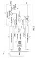
- an intelligent controller 205may be used in conjunction with a digital spectrum analyzer 210 to increase transmitter 215 efficiency and reduce unwanted spectral emissions by adjusting certain controls within digital signal generation and conditioning circuitry 220 that receives an input signal from a modem 222 .
- spectral analysis measurementscan be used to adjust controls in peak-envelope reduction and digital pre-distortion functional blocks within the transmit waveform conditioner 220 .
- the digital spectrum analyzercan also be used with an optional analog power detector 230 to provide accurate measurements of absolute and relative spectral emissions at the output 235 . These measurements can be used by the intelligent controller 205 to increase transmitter 215 efficiency by reducing the power supply voltage to a power amplifier 240 until spectral emissions reach a maximum limit. Over-specification of the power amplifier (due to output power detector inaccuracy and erring on the side of higher power) can also be avoided by measuring spectral emissions and reducing transmitter gain only if spectral emissions are above maximum limits.
- the digital spectrum analyzer 210can be used on signals within a receive waveform conditioner 255 to measure the performance of the analog hardware indicated by broken line 250 .
- the spectrum analyzer 210can be used to measure: (1) noise-floor, (2) spurious emissions, (3) selectivity, and (4) nonlinearity of the analog receiver.
- the spectrum analyzercan be used to perform network-level performance measurements of the receive communication link such as: (1) estimation of sensitivity and capacity limits due to receiver noise-floor, and (2) detection of interferers at the receiver input.
- Transmit waveform conditioner 220contains blocks which perform per-carrier, composite (multi-carrier), and pre-distortion digital signal processing as shown in FIG. 3 .
- Per-carrier signal processing blocks 310 , 315 and 320may perform functions such as rate-changing, filtering, gain control, and frequency translation. While only three such per-carrier signal processing blocks are shown, there may be many more if more than three carriers are present.
- a composite signal processing block 325may perform functions such as rate-changing, peak-power reduction, filtering, and gain control.
- a digital pre-distortion block 330contains algorithms for performing the inverse of the power amplifier nonlinear distortion characteristic. To improve transmitter performance and efficiency, the digital spectrum analyzer 210 can perform real-time spectral measurements on any digital waveform signal in the transmit waveform conditioner including the following:
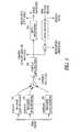
- the receive waveform conditioner 255contains blocks which perform impairment compensation 410 , composite (mulit-carrier) 415 , and per-carrier digital signal processing 420 , 425 , 430 as shown in FIG. 4 . While only three such per-carrier digital signal processing blocks are shown, there may be many more if more than three carriers are present.
- the impairment compensation signal processing block 410may compensate for analog receiver impairments such as IQ imbalance, DC offset, and nonlinearity.
- the composite signal processing block 415may perform functions such as filtering, rate-changing, and gain control.
- the per-carrier signal processing block 420 , 425 , 430may perform functions such as frequency translation, filtering, rate-changing and gain control.
- the digital spectrum analyzer 210can perform real-time spectral measurements on any digital waveform signal in the receive waveform conditioner including the following:
- the intelligent controller 205improves transmitter performance and efficiency by performing measurements using the spectrum analyzer 210 and making appropriate adjustments to controls in the transmit waveform conditioner 220 and analog transmitter 215 .
- the controller 205can have multiple and concurrent modes of operation for improving specific measures of performance.
- a power supply unit (PSU) control algorithmcan be used to reduce the average power consumption of the power amplifier 240 while guaranteeing compliance to conducted spurious emissions requirements. This algorithm would continuously repeat the following procedure:
- the Frequency Offset(s) and the two thresholds (Upper and Lower), which provide hysteresis,are determined by the relevant regulatory and air interface standards for the transmitter 215 .
- the over-specification of the power amplifier 240 due to output power detector 230 inaccuracycan be avoided by having the controller 205 reduce the transmitter gain when spectral emissions are above maximum limits and the PSU is at maximum voltage. This algorithm would continuously repeat the following procedure:
- a digital devicesuch as an FPGA, ASIC, or microprocessor can be used to implement the digital spectrum analyzer 210 in one embodiment.
- a digital spectrum analyzer 210can be constructed using several spectrum analysis channels 510 , 515 , 520 , three of which are shown in FIG. 5 .
- the multiple spectrum analysis channels 510 , 515 , 520can be used to monitor spectral emissions at several frequency offsets simultaneously, which is beneficial for transmitters that must adhere to spectral emissions limits at several different frequencies as prescribed by relevant regulatory standards.
- a spectrum analyzer channelsuch as channel 510 may be implemented as a mixer-based, flexible spectrum analyzer as shown in FIG. 6 .
- This architecturerepresents the digital-equivalent of a heterodyne-based spectrum analyzer which is often implemented in analog hardware in modern test equipment.
- the digital implementation of the analog spectrum analyzer architectureis found to be optimal for laying the foundations of an adaptive digital system for transceiver monitoring and control.
- An input multiplexer 610allows various signals 615 from within the digital device to be measured.
- a multiplier-based mixer 620 with a reset-able and programmable numerically controlled oscillator (NCO) 625is used to provide a frequency offset to the input digital signal 615 .
- NCOnumerically controlled oscillator
- a resolution bandwidth filter stage 630is used to limit spectral bandwidth of a subsequent power measurement.
- the resolution bandwidth filter 630can be made programmable so that different spectral bandwidths can be configured for a specific measurement.
- the resolution bandwidth filterdoes not have stringent phase response requirements therefore it can be implemented using an efficient digital structure (such as for example an infinite impulse response (IIR) filter).
- a variable gain device 635may be used to scale the digital signal to an appropriate level based on the dynamic range of a digital power detector 640 .
- the digital power detector 640is used to calculate the instantaneous power of the signal envelope, and an output filter 645 is used to perform power-averaging before a spectral power reading 650 is made available to various control or monitoring devices in the system.
- the flexibility of spectrum analyzer configurationie.
- input signal, frequency offset, resolution bandwidth, detector signal levelallows one instance of the spectrum analyzer channel to be shared, in a time-multiplexed manner, amongst various monitoring functions in the system.
- This implementation of a spectrum analyzermay be implemented with much less digital logic than more well-known FFT based methods.
- Various embodiments of the transceiver systemmay enable fast and effective transmit signal optimization. Optimization of peak-envelope reduction algorithms by real-time measurement of transmit signal spectrum, and optimization of pre-distortion algorithms by real-time measurement of transmit signal spectrum may be performed.
- Real-time transmitter control for increased transmitter efficiencymay be obtained due to lower power supply consumption by real-time measurement of transmit signal spectrum. This may eliminate the need for over-specification of power amplifier by real-time measurement of transmit signal spectrum. Continuous improvement of receiver performance and monitoring during operation may be obtained by measuring receiver noise-floor. Spurious signals from receiver hardware as well as interferers in receiver input spectrum, receiver selectivity and receiver linearity may be enabled.
- Flexible spectrum analyzer configurationis provided by a programmable input signal, frequency offset, resolution bandwidth, and dynamic range.
- one structuremay be shared amongst various optimization targets.
- Efficient spectrum analyzer implementationmay include measurement of spectral power at one frequency offset and efficient digital logic implementation.
- Use of envelope power detection and relaxed phase response requirements of the resolution bandwidth filtermay also provide resource-efficient realizations such as infinite-impulse response (IIR) filters.
- IIRinfinite-impulse response
- one structuremay provide spectral analysis with increasingly narrower resolution bandwidth for the same amount of computational complexity, while preserving optimization methods that may be implemented.
- Over-specification of power amplifiermay be avoided by measuring output spectral characteristics. Varying power supply voltage and/or amplifier gain enables the output frequency characteristic to be within an acceptable margin of a desired frequency mask.
- the optimization methodsmay be applied to improve the performance, efficiency and size of signal transceivers in different fields such as, but not limited to, RF transmission, Hi-Fi audio, Hi-Fi video, optical transmission and, generally, in systems where high-quality of electrical/electro-mechanical/electro-optical/electro-magnetic signal transmission and reception has to be achieved.
- the system 100may reduce transceiver inefficiency and over-specification by employing spectral analysis of signals within a system composed of a signal transmitter and receiver.
- the cost of transmittersmay be reduced by digital waveform conditioning algorithms. These algorithms are enhanced by spectral analysis of internal digital waveforms and the transmitted output spectrum.
- Operating voltage and output power of the transmitter power amplifiermay be optimized using spectral measurements of the output transmit signal using a feedback (or observation) receiver.
- the digital spectrum analyzercan be used to detect unwanted interferers and measure performance of the receiver analog hardware.
- a resource-efficient digital spectrum analyzer architecturewhich need not involve computationally expensive approaches such as fast Fourier transforms (also known as FFT), and an intelligent resource-managing controller paired with it.
- the controller intelligencemay be provided by a finite state machine responsible for specifying the generic spectrum analyzer (SA) configuration for a given transceiver application.
- SAgeneric spectrum analyzer
- general purpose computers or programmable logic arrays or other devices capable of performing the functions describedmay be used.
Landscapes
- Engineering & Computer Science (AREA)
- Computer Networks & Wireless Communication (AREA)
- Signal Processing (AREA)
- Transmitters (AREA)
Abstract
Description
- Composite Signal Processing Input
- Composite Signal Processing Output
- Predistortion Input
- Predistortion Output
- Feedback Signal
- Predistortion Error Signal
- Impairment Compensation Input
- Impairment Compensation Output
- Composite Signal Processing Output
- Per-Carrier Signal Processing Outputs
- 1. Obtain spectral measurement at Frequency Offset(s)
- 2. If (spectral measurement<Lower Threshold) then decrease PSU voltage
- 3. If (spectral measurement>Upper Threshold) then increase PSU voltage
- 1. Obtain spectral measurement at Frequency Offset(s)
- 2. If PSU voltage at maximum then
- if (spectral measurement>Threshold) then
- decrease transmitter gain
- if (spectral measurement>Threshold) then
Claims (12)
Priority Applications (1)
| Application Number | Priority Date | Filing Date | Title |
|---|---|---|---|
| US11/688,742US8995502B1 (en) | 2006-04-04 | 2007-03-20 | Transceiver with spectral analysis |
Applications Claiming Priority (2)
| Application Number | Priority Date | Filing Date | Title |
|---|---|---|---|
| US78896906P | 2006-04-04 | 2006-04-04 | |
| US11/688,742US8995502B1 (en) | 2006-04-04 | 2007-03-20 | Transceiver with spectral analysis |
Publications (1)
| Publication Number | Publication Date |
|---|---|
| US8995502B1true US8995502B1 (en) | 2015-03-31 |
Family
ID=52707911
Family Applications (1)
| Application Number | Title | Priority Date | Filing Date |
|---|---|---|---|
| US11/688,742Expired - Fee RelatedUS8995502B1 (en) | 2006-04-04 | 2007-03-20 | Transceiver with spectral analysis |
Country Status (1)
| Country | Link |
|---|---|
| US (1) | US8995502B1 (en) |
Cited By (16)
| Publication number | Priority date | Publication date | Assignee | Title |
|---|---|---|---|---|
| US20140118065A1 (en)* | 2012-10-30 | 2014-05-01 | Eta Devices, Inc. | Linearization Circuits And Methods For Multilevel Power Amplifier Systems |
| US20140363033A1 (en)* | 2013-06-11 | 2014-12-11 | DSP Group | Equalization and power control of bone conduction elements |
| US20140370883A1 (en)* | 2011-08-17 | 2014-12-18 | Luke Cirillo | Method and a device for the automatic allocation of a signal to a measurement application |
| US20150023237A1 (en)* | 2009-04-23 | 2015-01-22 | Maxlinear, Inc. | Channel-sensitive power control |
| US9166536B2 (en) | 2012-10-30 | 2015-10-20 | Eta Devices, Inc. | Transmitter architecture and related methods |
| CN105354268A (en)* | 2015-10-27 | 2016-02-24 | 国网山东省电力公司济南供电公司 | Meter reading data management system |
| US9531291B2 (en) | 2012-06-25 | 2016-12-27 | Eta Devices, Inc. | Transmission-line resistance compression networks and related techniques |
| US9537456B2 (en) | 2012-10-30 | 2017-01-03 | Eta Devices, Inc. | Asymmetric multilevel backoff amplifier with radio-frequency splitter |
| US20170062186A1 (en)* | 2015-08-27 | 2017-03-02 | Mks Instruments, Inc. | Feedback Control By RF Waveform Tailoring for Ion Energy Distribution |
| US9768731B2 (en) | 2014-07-23 | 2017-09-19 | Eta Devices, Inc. | Linearity and noise improvement for multilevel power amplifier systems using multi-pulse drain transitions |
| US9912387B2 (en)* | 2014-12-30 | 2018-03-06 | Solid, Inc. | Distributed antenna system including crest factor reduction module disposed at optimum position |
| US9979421B2 (en) | 2015-03-02 | 2018-05-22 | Eta Devices, Inc. | Digital pre-distortion (DPD) training and calibration system and related techniques |
| US10693527B2 (en) | 2014-12-30 | 2020-06-23 | Solid, Inc. | Distributed antenna system including crest factor reduction module disposed at optimum position |
| US10897733B2 (en)* | 2016-09-28 | 2021-01-19 | Apple Inc. | Apparatuses and methods for measuring neighboring inter-frequency or inter-rat cells |
| CN114422043A (en)* | 2022-03-28 | 2022-04-29 | 成都嘉纳海威科技有限责任公司 | Reliability test device and method |
| US20230063376A1 (en)* | 2021-08-25 | 2023-03-02 | Samsung Electronics Co., Ltd. | Communication device and operating method thereof |
Citations (31)
| Publication number | Priority date | Publication date | Assignee | Title |
|---|---|---|---|---|
| US4577334A (en) | 1984-01-13 | 1986-03-18 | Ncr Corporation | Digital data receiver including timing adjustment circuit |
| US4717894A (en) | 1986-10-23 | 1988-01-05 | Hewlett-Packard Company | Calibration of vector modulators using a scalar detector |
| US5049832A (en) | 1990-04-20 | 1991-09-17 | Simon Fraser University | Amplifier linearization by adaptive predistortion |
| US5113414A (en) | 1989-10-06 | 1992-05-12 | U.S. Philips Corporation | Predistortion arrangement for a digital transmission system |
| US5119399A (en) | 1990-09-28 | 1992-06-02 | Hewlett-Packard Co. | Quadrature measurement and calibration of a vector modulator |
| US5371481A (en) | 1993-03-24 | 1994-12-06 | Nokia Mobile Phones Ltd. | Tuning techniques for I/Q channel signals in microwave digital transmission systems |
| US5524285A (en) | 1993-11-02 | 1996-06-04 | Wray; Anthony J. | Radio transmitter with power amplifier and linearization |
| US5613226A (en) | 1993-11-30 | 1997-03-18 | Nec Corporation | Linear transmitter for use in combination with radio communication systems |
| US5732333A (en) | 1996-02-14 | 1998-03-24 | Glenayre Electronics, Inc. | Linear transmitter using predistortion |
| US5740520A (en) | 1996-04-03 | 1998-04-14 | State Of Israel | Channel correction transceiver |
| US5786728A (en) | 1995-06-30 | 1998-07-28 | Nokia Mobile Phones, Ltd. | Cuber based predistortion circuit and mobile station using the same |
| US5990738A (en) | 1998-06-19 | 1999-11-23 | Datum Telegraphic Inc. | Compensation system and methods for a linear power amplifier |
| US6133789A (en) | 1997-12-10 | 2000-10-17 | Nortel Networks Corporation | Method and system for robustly linearizing a radio frequency power amplifier using vector feedback |
| US6147553A (en) | 1998-03-06 | 2000-11-14 | Fujant, Inc. | Amplification using amplitude reconstruction of amplitude and/or angle modulated carrier |
| US6169463B1 (en) | 1999-03-24 | 2001-01-02 | Philips Electronic North America Corp. | Quadrature modulator with set-and-forget carrier leakage compensation |
| US6194964B1 (en) | 1998-07-07 | 2001-02-27 | Samsung Electronics Co., Ltd. | Predistorter having an automatic gain control circuit and method therefor |
| US6208698B1 (en) | 1996-10-24 | 2001-03-27 | Alcatel | Quadrature modulator imbalance estimator and modulator stage using it |
| US20010007435A1 (en)* | 1999-12-28 | 2001-07-12 | Fujitsu Limited | Distortion compensating apparatus |
| US6266517B1 (en) | 1999-12-30 | 2001-07-24 | Motorola, Inc. | Method and apparatus for correcting distortion in a transmitter |
| US6275685B1 (en)* | 1998-12-10 | 2001-08-14 | Nortel Networks Limited | Linear amplifier arrangement |
| US20010022532A1 (en) | 1999-12-21 | 2001-09-20 | Dolman Graham Ainsley | Phase and amplitude detector and method of determining errors |
| US6298096B1 (en) | 1998-11-19 | 2001-10-02 | Titan Corporation | Method and apparatus for determination of predistortion parameters for a quadrature modulator |
| US20020181611A1 (en) | 2001-06-01 | 2002-12-05 | Lg Electronics Inc. | Analog quadrature modulator (AQM) error compensating apparatus and method |
| US6600792B2 (en)* | 1998-06-26 | 2003-07-29 | Qualcomm Incorporated | Predistortion technique for high power amplifiers |
| US20030146791A1 (en) | 2002-02-06 | 2003-08-07 | Shvarts Emanuil Y. | Variable output power supply |
| US20050017801A1 (en)* | 2003-07-23 | 2005-01-27 | Andrew Corporation | Elimination of peak clipping and improved efficiency for RF power amplifiers with a predistorter |
| US20050025265A1 (en)* | 2003-07-31 | 2005-02-03 | D'amico Thomas V. | Method and apparatus for reducing interference within a communication system |
| US20050180527A1 (en)* | 2004-01-29 | 2005-08-18 | Ntt Docomo, Inc. | Digital predistorter using power series model |
| US7085315B1 (en)* | 2002-04-15 | 2006-08-01 | Vixs, Inc. | Digital demodulation utilizing frequency equalization |
| US7085330B1 (en) | 2002-02-15 | 2006-08-01 | Marvell International Ltd. | Method and apparatus for amplifier linearization using adaptive predistortion |
| US20060209984A1 (en)* | 2004-12-17 | 2006-09-21 | Andrew Corporation | Transmitter with an envelope tracking power amplifier utilizing digital predistortion of the signal envelope |
- 2007
- 2007-03-20USUS11/688,742patent/US8995502B1/ennot_activeExpired - Fee Related
Patent Citations (31)
| Publication number | Priority date | Publication date | Assignee | Title |
|---|---|---|---|---|
| US4577334A (en) | 1984-01-13 | 1986-03-18 | Ncr Corporation | Digital data receiver including timing adjustment circuit |
| US4717894A (en) | 1986-10-23 | 1988-01-05 | Hewlett-Packard Company | Calibration of vector modulators using a scalar detector |
| US5113414A (en) | 1989-10-06 | 1992-05-12 | U.S. Philips Corporation | Predistortion arrangement for a digital transmission system |
| US5049832A (en) | 1990-04-20 | 1991-09-17 | Simon Fraser University | Amplifier linearization by adaptive predistortion |
| US5119399A (en) | 1990-09-28 | 1992-06-02 | Hewlett-Packard Co. | Quadrature measurement and calibration of a vector modulator |
| US5371481A (en) | 1993-03-24 | 1994-12-06 | Nokia Mobile Phones Ltd. | Tuning techniques for I/Q channel signals in microwave digital transmission systems |
| US5524285A (en) | 1993-11-02 | 1996-06-04 | Wray; Anthony J. | Radio transmitter with power amplifier and linearization |
| US5613226A (en) | 1993-11-30 | 1997-03-18 | Nec Corporation | Linear transmitter for use in combination with radio communication systems |
| US5786728A (en) | 1995-06-30 | 1998-07-28 | Nokia Mobile Phones, Ltd. | Cuber based predistortion circuit and mobile station using the same |
| US5732333A (en) | 1996-02-14 | 1998-03-24 | Glenayre Electronics, Inc. | Linear transmitter using predistortion |
| US5740520A (en) | 1996-04-03 | 1998-04-14 | State Of Israel | Channel correction transceiver |
| US6208698B1 (en) | 1996-10-24 | 2001-03-27 | Alcatel | Quadrature modulator imbalance estimator and modulator stage using it |
| US6133789A (en) | 1997-12-10 | 2000-10-17 | Nortel Networks Corporation | Method and system for robustly linearizing a radio frequency power amplifier using vector feedback |
| US6147553A (en) | 1998-03-06 | 2000-11-14 | Fujant, Inc. | Amplification using amplitude reconstruction of amplitude and/or angle modulated carrier |
| US5990738A (en) | 1998-06-19 | 1999-11-23 | Datum Telegraphic Inc. | Compensation system and methods for a linear power amplifier |
| US6600792B2 (en)* | 1998-06-26 | 2003-07-29 | Qualcomm Incorporated | Predistortion technique for high power amplifiers |
| US6194964B1 (en) | 1998-07-07 | 2001-02-27 | Samsung Electronics Co., Ltd. | Predistorter having an automatic gain control circuit and method therefor |
| US6298096B1 (en) | 1998-11-19 | 2001-10-02 | Titan Corporation | Method and apparatus for determination of predistortion parameters for a quadrature modulator |
| US6275685B1 (en)* | 1998-12-10 | 2001-08-14 | Nortel Networks Limited | Linear amplifier arrangement |
| US6169463B1 (en) | 1999-03-24 | 2001-01-02 | Philips Electronic North America Corp. | Quadrature modulator with set-and-forget carrier leakage compensation |
| US20010022532A1 (en) | 1999-12-21 | 2001-09-20 | Dolman Graham Ainsley | Phase and amplitude detector and method of determining errors |
| US20010007435A1 (en)* | 1999-12-28 | 2001-07-12 | Fujitsu Limited | Distortion compensating apparatus |
| US6266517B1 (en) | 1999-12-30 | 2001-07-24 | Motorola, Inc. | Method and apparatus for correcting distortion in a transmitter |
| US20020181611A1 (en) | 2001-06-01 | 2002-12-05 | Lg Electronics Inc. | Analog quadrature modulator (AQM) error compensating apparatus and method |
| US20030146791A1 (en) | 2002-02-06 | 2003-08-07 | Shvarts Emanuil Y. | Variable output power supply |
| US7085330B1 (en) | 2002-02-15 | 2006-08-01 | Marvell International Ltd. | Method and apparatus for amplifier linearization using adaptive predistortion |
| US7085315B1 (en)* | 2002-04-15 | 2006-08-01 | Vixs, Inc. | Digital demodulation utilizing frequency equalization |
| US20050017801A1 (en)* | 2003-07-23 | 2005-01-27 | Andrew Corporation | Elimination of peak clipping and improved efficiency for RF power amplifiers with a predistorter |
| US20050025265A1 (en)* | 2003-07-31 | 2005-02-03 | D'amico Thomas V. | Method and apparatus for reducing interference within a communication system |
| US20050180527A1 (en)* | 2004-01-29 | 2005-08-18 | Ntt Docomo, Inc. | Digital predistorter using power series model |
| US20060209984A1 (en)* | 2004-12-17 | 2006-09-21 | Andrew Corporation | Transmitter with an envelope tracking power amplifier utilizing digital predistortion of the signal envelope |
Non-Patent Citations (4)
| Title |
|---|
| Faulkner, M. , et al., "Amplifier Linearisation Using RF Feedback and Feedforward Techniques", Proceedings of the IEEE Vehicular Technology Conference, Chicago, IL,(Jul. 25, 1995),525-529. |
| Jones, A. E., et al., "Phase error correcting vector modulator for personal communications network(PCN) transceivers", Electronics Letters, 27(14), (Jul. 4, 1991),1230-1231. |
| Lohtia, A. , et al., "Power Amplifier Linearization Using Cubic Spline Interpolation", IEEE Vehicular Technology Conference, (May 18-20, 1993),676-679. |
| Sano, A. , et al., "Identification of Hammerstein-Wiener System with Application to Compensation for Nonlinear Distortion", SICE 2002; Proceedings of the 41st SICE Annual Conference; vol. 3, (Aug. 5-7, 2002),1521-1526. |
Cited By (32)
| Publication number | Priority date | Publication date | Assignee | Title |
|---|---|---|---|---|
| US9609599B2 (en)* | 2009-04-23 | 2017-03-28 | Maxlinear, Inc. | Channel-sensitive power control |
| US20150023237A1 (en)* | 2009-04-23 | 2015-01-22 | Maxlinear, Inc. | Channel-sensitive power control |
| US9363698B2 (en)* | 2011-08-17 | 2016-06-07 | Rohde & Schwarz Gmbh & Co. Kg | Method and a device for the automatic allocation of a signal to a measurement application |
| US20140370883A1 (en)* | 2011-08-17 | 2014-12-18 | Luke Cirillo | Method and a device for the automatic allocation of a signal to a measurement application |
| US9531291B2 (en) | 2012-06-25 | 2016-12-27 | Eta Devices, Inc. | Transmission-line resistance compression networks and related techniques |
| US9166536B2 (en) | 2012-10-30 | 2015-10-20 | Eta Devices, Inc. | Transmitter architecture and related methods |
| US10038461B2 (en) | 2012-10-30 | 2018-07-31 | Eta Devices, Inc. | RF amplifier having a transition shaping filter |
| US9209758B2 (en) | 2012-10-30 | 2015-12-08 | Eta Devices, Inc. | RF amplifier having discrete supply voltages |
| US20140118065A1 (en)* | 2012-10-30 | 2014-05-01 | Eta Devices, Inc. | Linearization Circuits And Methods For Multilevel Power Amplifier Systems |
| US20190074797A1 (en)* | 2012-10-30 | 2019-03-07 | Eta Devices, Inc. | Linearization Circuits And Methods For Multilevel Power Amplifier Systems |
| US9490752B2 (en) | 2012-10-30 | 2016-11-08 | Eta Devices, Inc. | RF amplifier having a transition shaping filter |
| US9160287B2 (en)* | 2012-10-30 | 2015-10-13 | Eta Devices, Inc. | Linearization circuits and methods for multilevel power amplifier systems |
| US9537456B2 (en) | 2012-10-30 | 2017-01-03 | Eta Devices, Inc. | Asymmetric multilevel backoff amplifier with radio-frequency splitter |
| US10658981B2 (en)* | 2012-10-30 | 2020-05-19 | Eta Devices, Inc. | Linearization circuits and methods for multilevel power amplifier systems |
| US9172336B2 (en) | 2012-10-30 | 2015-10-27 | Ela Devices, Inc. | Method and apparatus for multilevel power amplification |
| US10164577B2 (en) | 2012-10-30 | 2018-12-25 | Eta Devices, Inc. | Linearization circuits and methods for multilevel power amplifier systems |
| US9768732B2 (en) | 2012-10-30 | 2017-09-19 | Eta Devices, Inc. | Asymmetric multilevel backoff amplifier with radio-frequency splitter |
| US9596534B2 (en)* | 2013-06-11 | 2017-03-14 | Dsp Group Ltd. | Equalization and power control of bone conduction elements |
| US20140363033A1 (en)* | 2013-06-11 | 2014-12-11 | DSP Group | Equalization and power control of bone conduction elements |
| US9768731B2 (en) | 2014-07-23 | 2017-09-19 | Eta Devices, Inc. | Linearity and noise improvement for multilevel power amplifier systems using multi-pulse drain transitions |
| US9912387B2 (en)* | 2014-12-30 | 2018-03-06 | Solid, Inc. | Distributed antenna system including crest factor reduction module disposed at optimum position |
| US10693527B2 (en) | 2014-12-30 | 2020-06-23 | Solid, Inc. | Distributed antenna system including crest factor reduction module disposed at optimum position |
| US9979421B2 (en) | 2015-03-02 | 2018-05-22 | Eta Devices, Inc. | Digital pre-distortion (DPD) training and calibration system and related techniques |
| US10395895B2 (en)* | 2015-08-27 | 2019-08-27 | Mks Instruments, Inc. | Feedback control by RF waveform tailoring for ion energy distribution |
| US20170062186A1 (en)* | 2015-08-27 | 2017-03-02 | Mks Instruments, Inc. | Feedback Control By RF Waveform Tailoring for Ion Energy Distribution |
| US10692698B2 (en) | 2015-08-27 | 2020-06-23 | Mks Instruments, Inc. | Feedback control by RF waveform tailoring for ion energy distribution |
| CN105354268B (en)* | 2015-10-27 | 2018-12-28 | 国网山东省电力公司济南供电公司 | A kind of meter reading data management system |
| CN105354268A (en)* | 2015-10-27 | 2016-02-24 | 国网山东省电力公司济南供电公司 | Meter reading data management system |
| US10897733B2 (en)* | 2016-09-28 | 2021-01-19 | Apple Inc. | Apparatuses and methods for measuring neighboring inter-frequency or inter-rat cells |
| US20230063376A1 (en)* | 2021-08-25 | 2023-03-02 | Samsung Electronics Co., Ltd. | Communication device and operating method thereof |
| US11863226B2 (en)* | 2021-08-25 | 2024-01-02 | Samsung Electronics Co., Ltd. | Communication device and operating method thereof |
| CN114422043A (en)* | 2022-03-28 | 2022-04-29 | 成都嘉纳海威科技有限责任公司 | Reliability test device and method |
Similar Documents
| Publication | Publication Date | Title |
|---|---|---|
| US8995502B1 (en) | Transceiver with spectral analysis | |
| US7415250B2 (en) | Distortion compensating amplifier | |
| US8218677B2 (en) | Transmitter characterization for digital pre-distortion using offset preamble subcarriers | |
| US8705595B2 (en) | Digital output power measurement in radio communication systems | |
| US9998241B2 (en) | Envelope tracking (ET) closed-loop on-the-fly calibration | |
| EP3032738B1 (en) | Method and apparatus for correcting inconvenient power amplifier load characteristics in an envelope tracking based system | |
| JP4855267B2 (en) | Signal extraction circuit and distortion compensation amplifier having the same | |
| EP2575310B1 (en) | Method and device for digital baseband predistortion | |
| US9344041B2 (en) | Polar amplification transmitter distortion reduction | |
| CN105027429A (en) | Et system with adjustment for noise | |
| WO2008019285A2 (en) | Low distortion radio frequency (rf) limiter | |
| WO2004112235A2 (en) | Method and system for transmitting signals with reduced spurious emissions | |
| CN102340283A (en) | Method and device for envelope tracking | |
| EP2779555B1 (en) | Method and apparatus for adjusting predistortion coefficients | |
| JP5345268B2 (en) | Apparatus and method for generating an amplified signal using multiple amplitudes across a spectrum | |
| US9668208B2 (en) | Operating point setting of an amplifier | |
| JP2013541294A (en) | Control method, wireless communication system and power detection method | |
| WO2013028395A1 (en) | Apparatus and method for operating a transmitter | |
| US7593699B2 (en) | Distortion/efficiency adaptation in a variable-data-rate radio transmitter | |
| US20080317165A1 (en) | Systems and methods of calibrating a transmitter | |
| US9496838B2 (en) | Envelope tracking amplifier for a transmitter having a voltage mapping linearly related to the square of the amplitude of the baseband signal | |
| WO2021174463A1 (en) | Digital predistortion device and transmitter | |
| CN107276701B (en) | Method and device for detecting sub-carrier power and radio remote unit | |
| CN202737812U (en) | Power amplifying device applied to long-term evolution (LTE) system | |
| US8989250B1 (en) | Method and apparatus for equalizing distortion in a digital pre-distortion observation path |
Legal Events
| Date | Code | Title | Description |
|---|---|---|---|
| AS | Assignment | Owner name:NORTEL NETWORKS LIMITED, CANADA Free format text:ASSIGNMENT OF ASSIGNORS INTEREST;ASSIGNORS:LAI, STEPHEN;RASHEV, PETER ZAHARIEV;REEL/FRAME:019038/0249 Effective date:20070320 | |
| AS | Assignment | Owner name:ROCKSTAR BIDCO, LP, NEW YORK Free format text:ASSIGNMENT OF ASSIGNORS INTEREST;ASSIGNOR:NORTEL NETWORKS LIMITED;REEL/FRAME:027143/0717 Effective date:20110729 | |
| AS | Assignment | Owner name:APPLE INC., CALIFORNIA Free format text:ASSIGNMENT OF ASSIGNORS INTEREST;ASSIGNOR:ROCKSTAR BIDCO, LP;REEL/FRAME:028605/0188 Effective date:20120511 | |
| FEPP | Fee payment procedure | Free format text:PAYOR NUMBER ASSIGNED (ORIGINAL EVENT CODE: ASPN); ENTITY STATUS OF PATENT OWNER: LARGE ENTITY | |
| STCF | Information on status: patent grant | Free format text:PATENTED CASE | |
| MAFP | Maintenance fee payment | Free format text:PAYMENT OF MAINTENANCE FEE, 4TH YEAR, LARGE ENTITY (ORIGINAL EVENT CODE: M1551); ENTITY STATUS OF PATENT OWNER: LARGE ENTITY Year of fee payment:4 | |
| FEPP | Fee payment procedure | Free format text:MAINTENANCE FEE REMINDER MAILED (ORIGINAL EVENT CODE: REM.); ENTITY STATUS OF PATENT OWNER: LARGE ENTITY | |
| LAPS | Lapse for failure to pay maintenance fees | Free format text:PATENT EXPIRED FOR FAILURE TO PAY MAINTENANCE FEES (ORIGINAL EVENT CODE: EXP.); ENTITY STATUS OF PATENT OWNER: LARGE ENTITY | |
| STCH | Information on status: patent discontinuation | Free format text:PATENT EXPIRED DUE TO NONPAYMENT OF MAINTENANCE FEES UNDER 37 CFR 1.362 | |
| FP | Lapsed due to failure to pay maintenance fee | Effective date:20230331 |