US8995137B2 - Modular mass storage system and method therefor - Google Patents
Modular mass storage system and method thereforDownload PDFInfo
- Publication number
- US8995137B2 US8995137B2US13/866,098US201313866098AUS8995137B2US 8995137 B2US8995137 B2US 8995137B2US 201313866098 AUS201313866098 AUS 201313866098AUS 8995137 B2US8995137 B2US 8995137B2
- Authority
- US
- United States
- Prior art keywords
- mass storage
- circuit board
- printed circuit
- storage system
- connectors
- Prior art date
- Legal status (The legal status is an assumption and is not a legal conclusion. Google has not performed a legal analysis and makes no representation as to the accuracy of the status listed.)
- Active, expires
Links
Images

Classifications
- G—PHYSICS
- G06—COMPUTING OR CALCULATING; COUNTING
- G06F—ELECTRIC DIGITAL DATA PROCESSING
- G06F13/00—Interconnection of, or transfer of information or other signals between, memories, input/output devices or central processing units
- G06F13/38—Information transfer, e.g. on bus
- G06F13/40—Bus structure
- G06F13/4063—Device-to-bus coupling
- G06F13/4068—Electrical coupling
- G06F13/4081—Live connection to bus, e.g. hot-plugging
- G—PHYSICS
- G06—COMPUTING OR CALCULATING; COUNTING
- G06F—ELECTRIC DIGITAL DATA PROCESSING
- G06F3/00—Input arrangements for transferring data to be processed into a form capable of being handled by the computer; Output arrangements for transferring data from processing unit to output unit, e.g. interface arrangements
- G06F3/06—Digital input from, or digital output to, record carriers, e.g. RAID, emulated record carriers or networked record carriers
- G06F3/0601—Interfaces specially adapted for storage systems
- G06F3/0602—Interfaces specially adapted for storage systems specifically adapted to achieve a particular effect
- G06F3/0626—Reducing size or complexity of storage systems
- G—PHYSICS
- G06—COMPUTING OR CALCULATING; COUNTING
- G06F—ELECTRIC DIGITAL DATA PROCESSING
- G06F3/00—Input arrangements for transferring data to be processed into a form capable of being handled by the computer; Output arrangements for transferring data from processing unit to output unit, e.g. interface arrangements
- G06F3/06—Digital input from, or digital output to, record carriers, e.g. RAID, emulated record carriers or networked record carriers
- G06F3/0601—Interfaces specially adapted for storage systems
- G06F3/0628—Interfaces specially adapted for storage systems making use of a particular technique
- G06F3/0655—Vertical data movement, i.e. input-output transfer; data movement between one or more hosts and one or more storage devices
- G06F3/0658—Controller construction arrangements
- G—PHYSICS
- G06—COMPUTING OR CALCULATING; COUNTING
- G06F—ELECTRIC DIGITAL DATA PROCESSING
- G06F3/00—Input arrangements for transferring data to be processed into a form capable of being handled by the computer; Output arrangements for transferring data from processing unit to output unit, e.g. interface arrangements
- G06F3/06—Digital input from, or digital output to, record carriers, e.g. RAID, emulated record carriers or networked record carriers
- G06F3/0601—Interfaces specially adapted for storage systems
- G06F3/0668—Interfaces specially adapted for storage systems adopting a particular infrastructure
- G06F3/0671—In-line storage system
- G06F3/0683—Plurality of storage devices
Definitions
- the present inventiongenerally relates to computer memory systems, and more particularly to a modular mass storage system that enables storage devices to be installed and removed from a computer without the use of cables through which the storage devices receive power and exchange data with the motherboard of a computer system.
- HDDsrotatable media-based hard disk drives
- the 3.5-inch HDDsare still the predominant non-volatile storage device in desktop computers, where they are typically mounted in drive bays.
- the more common HDDis the 2.5-inch drives in a slim form factor mounted in a specialized compartment in the notebook chassis.
- the weight of an HDDplays an important factor with respect to the mounting of an HDD in a computer, since certain prerequisites must be met for the mounting fixture. Moreover there are also some orientational factors that must be taken into consideration, for example, drives mounted at an angle appear to have higher wear on their bearings than do drives oriented so that their spindle axes are vertical during normal operation of the computer. Finally and significantly, the mass of the actuator is often sufficient to cause some degree of movement of the entire drive.
- HDDsare often mounted in specialized drive bays within the chassis, often with the use of rubber grommets to dampen vibrations and shock between the HDDs and the chassis. Power and data connections are made through cables to the motherboard or any add-on host-bus controller, as well as the power supply unit (PSU) of the computer.
- PSUpower supply unit
- SSDssolid state drives
- Redundant arrays of independent diskswhich encompass computer data storage schemes that divide and replicate data among multiple HDDs, utilize a dedicated controller, such as an ISA (industry standard architecture) bus or a PCI (peripheral component interconnect) or PCI express (PCIe) expansion card.
- ISAindustry standard architecture
- PCIperipheral component interconnect
- PCIePCI express
- RAID controllersprovide a software-based RAID logic, which is sufficient for RAID Levels 0 and 1 (striping and mirroring, respectively) or a software-based RAID Level 5 configuration with distributed parity in which the central processing unit (CPU) handles the parity calculations.
- CPUcentral processing unit
- HBAhost bus adapter
- DMAdirect memory access
- the present inventionprovides a modular mass storage system and method that enables cableless mounting of ATA and/or similar high speed interface-based mass storage devices in a computer system.
- the modular mass storage systemincludes a printed circuit board, a system expansion slot interface on the printed circuit board and comprising power and data pins, a host bus controller on the printed circuit board and electrically connected to the system expansion slot interface, docking connectors connected with the host bus controller to receive power and exchange data therewith and adapted to electrically couple with industry-standard non-volatile memory devices without cabling therebetween, and means on the printed circuit board for securing the memory devices thereto once coupled to the docking connectors.
- the methodinvolves installing a mass storage system on a computer system.
- the mass storage systemcomprises a printed circuit board, a system expansion slot interface on the printed circuit board and comprising power and data pins, a host bus controller on the printed circuit board and electrically connected to the system expansion slot interface, docking connectors connected with the host bus controller to receive power and exchange data therewith and adapted to electrically couple with industry-standard non-volatile memory devices without cabling therebetween.
- Industry-standard non-volatile memory devicesare then installed in the mass storage system by removably coupling the memory devices to the docking connectors and removably securing the memory devices to the printed circuit board.
- the inventionfeatures means for mechanically and electrically integrating compliant mass storage devices as daughter devices or modules on a parent expansion card.
- a technical effect of this inventionis the elimination of cabling as a result of direct mounting of individual drives on a RAID adapter.
- the inventionpromotes a compact design of an entire mass storage device, as well as a modular design capable of using off-the-shelf drives to allow for customized configuration.
- the failed devicecan be replaced inexpensively without losing the entire mass storage device. If redundancy is used, an entire array of mass storage devices can be rebuilt on the fly without data loss.
- a direct PCl/PCIe interfacecan be used to allow for high data transfer rates. From an economics standpoint, an additional advantage is the ability to use multiple vendor standard devices, eliminating concerns associated with single-source solutions such as the Fusion-io card.
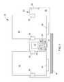
- FIG. 1is a schematic overview of a modular mass storage system for computer systems according to an embodiment of the present invention, wherein the system is configured as a host bus adapted that includes multiple mass storage devices (drives) removable engaged with docking connectors.
- drivesmass storage devices
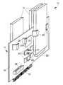
- FIG. 2is a perspective view of the modular mass storage system of FIG. 1 , with one of the drives removed to illustrate the mounting and interface to the drives.
- the present inventionprovides a compact, fully-integrated, modular mass storage system 10 for computer systems.
- the mass storage system 10is generally configured as a host bus adapter (HBA) comprising an expansion card 12 , represented in FIGS. 1 and 2 as a PCI express (PCIe) expansion card, on which an array of data (mass) storage devices 14 associated with the host bus adapter are individually removably mounted.
- HBAhost bus adapter
- PCIePCI express
- the electronics of the host bus adapterserve to connect the storage devices 14 to a computer (not shown) or other host system.
- the storage devices 14may be ATA and/or similar high speed interface-based mass storage devices having commonly-utilized mass memory drive configurations, including but not limited to IDE (integrated drive electronics) mode, advanced host computer interface (MCI), and RAID Levels 0, 1, 10 and 5.
- IDEintegrated drive electronics
- MCIadvanced host computer interface
- the expansion card 12 in FIGS. 1 and 2comprises a printed circuit board 16 on which are the electronics of the host bus adapter are mounted, which in FIG. 1 includes a RAID controller 18 along with auxiliary electronics such as a data cache 20 of integrated circuit memory devices such as SDRAM (synchronous dynamic random access memory), SRAM (static random access memory) or pipeline burst SRAM chips for data buffering, and a voltage regulator module represented as including a MOSFET 22 and capacitors 24 .
- auxiliary electronicssuch as a data cache 20 of integrated circuit memory devices such as SDRAM (synchronous dynamic random access memory), SRAM (static random access memory) or pipeline burst SRAM chips for data buffering, and a voltage regulator module represented as including a MOSFET 22 and capacitors 24 .
- a MOSFET 22 and capacitors 24a voltage regulator module represented as including a MOSFET 22 and capacitors 24 .
- parity calculationscan be carried out in software using the central processor on the computer system motherboard (not shown) or a dedicated parity processor (not shown) on the card
- the storage devices 14have male connectors (not shown) by which they are directly plugged into female docking connectors 28 on the card 12 .
- the connectors 28preferably provide both power and data connections for the storage devices 14 , similar to SATA drives.
- the data cache 20is used to buffer writes and/or prefetch reads from the array of storage devices 14 .
- a system expansion slot interface 30 in the form of a PCIe edge connectorprovides an interface with an expansion slot of the motherboard for supplying power to the card 12 and exchanging data between the card 12 and motherboard.
- An auxiliary power connector 32is also shown by which additional power can be supplied to the card 12 , if so desired. Electrical connections (not shown) on the card 12 can be achieved in accordance with conventional industry practices.
- FIG. 2represents a perspective view of the system 10 of FIG. 1 , with one of the storage devices 14 removed to illustrate the mounting and interface of the storage devices 14 with the docking connectors 28 and retention brackets 26 .
- both sides of the card 12can carry storage devices 14 , as well as their connectors 28 .
- the retention brackets 26provide the mechanical stability required for the storage devices 14 on the card 12 , and serve as mechanical fixtures that help to align each individual device 14 as it is inserted into its docking connector 28 .
- the brackets 26are preferably somewhat pliable and configured to allow the storage devices 14 to slide between distal arms 26 A ( FIG. 2 ) of the brackets 26 in a direction parallel to the surface of the printed circuit board 16 while applying sufficient force normal to the board surface to secure the storage devices 14 against the board surface.
- the number of docking connectors 28can vary, depending on the length of the card 12 . In the embodiment of FIGS. 1 and 2 , four docking connectors 28 are shown though it should be understood that any number of connectors 28 could be provided, including a single connector. Because of the bandwidth requirements of the card 12 and its storage devices 14 , the expansion slot interface 30 will typically use eight lanes for signaling, though a single lane, four lanes or sixteen lanes are also possible.
- the docking connectors 28 and expansion slot interface 30provide for cableless mounting and interfacing of the multiple mass storage devices 14 . Because it is advantageous to keep the amount of external cabling at a minimum, the power connections of the expansion slot interface 30 preferably use the full length of the interface 30 , even if the data connections only use a fraction of the lanes available.
- the optional auxiliary power connector 32 on the card 12can be used to supply auxiliary power from the system's motherboard to the card 12 independent of power supplied to the card 12 by the interface 30 .
- the mass storage system 10can be installed on a motherboard of a computer before and after installing and securing the storage devices 14 on the card 12 . It can also be seen that one or more of the storage devices 14 can be removed from the mass storage system 10 by simply uncoupling the device 14 from its corresponding docking connector 28 .
- USB (Universal Serial Bus) flash (thumb) drivesmay be mounted in one or more of the docking connectors 28 of the expansion card 12 in a manner similar to what is shown in FIGS. 1 and 2 and described above. This configuration may become more attractive with the emergence of the USB Revision 3.0 “Superspeed” standard (USB 3.0).
- HDMIhigh-definition multimedia interface
- IEEE 1394 interfacee.g., Apple's FIREWIRE
- SO-DIMMssmall outline dual in-line memory modules
Landscapes
- Engineering & Computer Science (AREA)
- Theoretical Computer Science (AREA)
- General Engineering & Computer Science (AREA)
- Physics & Mathematics (AREA)
- General Physics & Mathematics (AREA)
- Human Computer Interaction (AREA)
- Computer Hardware Design (AREA)
- Power Sources (AREA)
Abstract
Description
Claims (12)
Priority Applications (1)
| Application Number | Priority Date | Filing Date | Title |
|---|---|---|---|
| US13/866,098US8995137B2 (en) | 2009-03-23 | 2013-04-19 | Modular mass storage system and method therefor |
Applications Claiming Priority (3)
| Application Number | Priority Date | Filing Date | Title |
|---|---|---|---|
| US16248809P | 2009-03-23 | 2009-03-23 | |
| US12/713,349US8446729B2 (en) | 2009-03-23 | 2010-02-26 | Modular mass storage system and method therefor |
| US13/866,098US8995137B2 (en) | 2009-03-23 | 2013-04-19 | Modular mass storage system and method therefor |
Related Parent Applications (1)
| Application Number | Title | Priority Date | Filing Date |
|---|---|---|---|
| US12/713,349DivisionUS8446729B2 (en) | 2009-03-23 | 2010-02-26 | Modular mass storage system and method therefor |
Publications (2)
| Publication Number | Publication Date |
|---|---|
| US20130232298A1 US20130232298A1 (en) | 2013-09-05 |
| US8995137B2true US8995137B2 (en) | 2015-03-31 |
Family
ID=42738606
Family Applications (2)
| Application Number | Title | Priority Date | Filing Date |
|---|---|---|---|
| US12/713,349Active2031-12-25US8446729B2 (en) | 2009-03-23 | 2010-02-26 | Modular mass storage system and method therefor |
| US13/866,098Active2030-10-01US8995137B2 (en) | 2009-03-23 | 2013-04-19 | Modular mass storage system and method therefor |
Family Applications Before (1)
| Application Number | Title | Priority Date | Filing Date |
|---|---|---|---|
| US12/713,349Active2031-12-25US8446729B2 (en) | 2009-03-23 | 2010-02-26 | Modular mass storage system and method therefor |
Country Status (1)
| Country | Link |
|---|---|
| US (2) | US8446729B2 (en) |
Families Citing this family (48)
| Publication number | Priority date | Publication date | Assignee | Title |
|---|---|---|---|---|
| AU2003285949A1 (en) | 2002-10-22 | 2004-05-13 | Isys Technologies | Non-peripherals processing control module having improved heat dissipating properties |
| BR0315613A (en) | 2002-10-22 | 2005-08-23 | Jason A Sullivan | Systems and methods for providing a dynamically modular processing unit |
| BR0315624A (en) | 2002-10-22 | 2005-08-23 | Jason A Sullivan | Rugged Customizable Computer Processing System |
| US8310836B2 (en)* | 2009-05-21 | 2012-11-13 | Ocz Technology Group, Inc. | Mass storage device for a computer system and method therefor |
| US8554975B2 (en)* | 2009-06-23 | 2013-10-08 | Celestica International Inc. | Mass storage device and mass storage assembly |
| US9311018B2 (en)* | 2010-05-11 | 2016-04-12 | Taejin Info Tech Co., Ltd. | Hybrid storage system for a multi-level RAID architecture |
| JP4806084B1 (en)* | 2010-05-28 | 2011-11-02 | 株式会社東芝 | Information processing device |
| JP5685848B2 (en)* | 2010-07-27 | 2015-03-18 | 富士通株式会社 | Computer, program, and computer control method |
| US8693208B2 (en)* | 2010-08-06 | 2014-04-08 | Ocz Technology Group, Inc. | PCIe bus extension system, method and interfaces therefor |
| US9229816B2 (en)* | 2011-03-14 | 2016-01-05 | Taejin Info Tech Co., Ltd. | Hybrid system architecture for random access memory |
| CN102831919A (en)* | 2011-06-15 | 2012-12-19 | 鸿富锦精密工业(深圳)有限公司 | Solid state disk and mainboard for supporting same |
| CN102890534A (en)* | 2011-07-22 | 2013-01-23 | 鸿富锦精密工业(深圳)有限公司 | Mainboard with solid-state disk |
| CN102929331A (en)* | 2011-08-08 | 2013-02-13 | 鸿富锦精密工业(深圳)有限公司 | Expansion device for solid state drives and mainboard supporting expansion device |
| CN102955497A (en)* | 2011-08-18 | 2013-03-06 | 鸿富锦精密工业(深圳)有限公司 | Mainboard provided with solid-state drive |
| CN102999097A (en)* | 2011-09-15 | 2013-03-27 | 鸿富锦精密工业(深圳)有限公司 | Expansion card and mainboard supporting expansion card |
| US20130170129A1 (en)* | 2011-11-10 | 2013-07-04 | Jason A. Sullivan | Systems and methods for providing a dynamic electronic storage unit |
| CN103163974A (en)* | 2011-12-09 | 2013-06-19 | 鸿富锦精密工业(深圳)有限公司 | SSD combination |
| CN103163987A (en)* | 2011-12-15 | 2013-06-19 | 鸿富锦精密工业(深圳)有限公司 | Solid state drive combination |
| CN103186178A (en)* | 2011-12-29 | 2013-07-03 | 鸿富锦精密工业(深圳)有限公司 | Main board |
| KR20130097481A (en)* | 2012-02-24 | 2013-09-03 | 삼성전자주식회사 | Printed circuit board(pcb), and memory module comprising the same pcb |
| CN103365348A (en)* | 2012-04-06 | 2013-10-23 | 鸿富锦精密工业(深圳)有限公司 | Main board provided with electronic hard disk |
| CN103377167A (en)* | 2012-04-26 | 2013-10-30 | 鸿富锦精密工业(深圳)有限公司 | Data transmission device and SATA (Serial Advanced Technology Attachment) device module thereof |
| US9141152B2 (en)* | 2012-05-04 | 2015-09-22 | Hewlett-Packard Devlopment Company, L.P. | Interface card mount |
| USD709894S1 (en)* | 2012-09-22 | 2014-07-29 | Apple Inc. | Electronic device |
| US8753138B2 (en) | 2012-10-09 | 2014-06-17 | International Business Machines Corporation | Memory module connector with auxiliary power |
| US8856417B2 (en)* | 2012-10-09 | 2014-10-07 | International Business Machines Corporation | Memory module connector with auxiliary power cable |
| US9116679B2 (en) | 2013-03-14 | 2015-08-25 | Western Digital Technologies, Inc. | Storage device powered by a communications interface |
| US9330029B1 (en)* | 2013-06-28 | 2016-05-03 | Emc Corporation | Multiple connector IO board for receiving multiple I/O stream |
| US9585290B2 (en) | 2013-07-15 | 2017-02-28 | Skyera, Llc | High capacity storage unit |
| US9600038B2 (en)* | 2013-11-21 | 2017-03-21 | Skyera, Llc | Systems and methods for securing high density SSDs |
| US9304557B2 (en) | 2013-11-21 | 2016-04-05 | Skyera, Llc | Systems and methods for packaging high density SSDS |
| WO2016085493A1 (en) | 2014-11-26 | 2016-06-02 | Hewlett Packard Enterprise Development Lp | Storage drive carrier module |
| CN105742906A (en)* | 2014-12-12 | 2016-07-06 | 鸿富锦精密工业(武汉)有限公司 | Router |
| CN204257864U (en) | 2014-12-25 | 2015-04-08 | 纬创资通(中山)有限公司 | Interface card stuck-module |
| TWI566099B (en)* | 2014-12-30 | 2017-01-11 | 鴻海精密工業股份有限公司 | Electronic device with integrating function and multiple device integrating control method |
| WO2016122505A1 (en)* | 2015-01-29 | 2016-08-04 | Hewlett-Packard Development Company, L.P. | Memory card expansion |
| US10185374B2 (en)* | 2015-01-30 | 2019-01-22 | Hewlett Packard Enterprise Development Lp | Storage drive riser |
| US20160259754A1 (en) | 2015-03-02 | 2016-09-08 | Samsung Electronics Co., Ltd. | Hard disk drive form factor solid state drive multi-card adapter |
| TWI536179B (en)* | 2015-07-02 | 2016-06-01 | 緯創資通股份有限公司 | Connecting circuitry and computing system haveing the same |
| KR20170009652A (en)* | 2015-07-17 | 2017-01-25 | 삼성전자주식회사 | Wiring board and memory system including the same |
| US10714148B2 (en)* | 2015-12-30 | 2020-07-14 | Shenzhen Longsys Electronics Co., Ltd. | SSD storage module, SSD component, and SSD |
| CA169446S (en)* | 2016-01-22 | 2017-02-21 | Shenzhen Longsys Electronics Co Ltd | Ssd storage module |
| US9899358B2 (en)* | 2016-05-24 | 2018-02-20 | Intel Corporation | Module stacking mechanism with integrated ground |
| CN108256615B (en)* | 2016-12-28 | 2021-03-02 | 上海宝存信息科技有限公司 | Storage device |
| KR102219897B1 (en)* | 2017-12-28 | 2021-02-24 | 주식회사 펜터다임 | An input-output terminal disconnected industrial computer main-board in non-cable type and an industrial computer using the same |
| US11818842B1 (en)* | 2020-03-06 | 2023-11-14 | Amazon Technologies, Inc. | Configurable circuit board for abstracting third-party controls |
| US11600306B2 (en)* | 2020-11-24 | 2023-03-07 | Msg Entertainment Group, Llc | Enclosure for coupling storage device to a computer |
| US12355170B2 (en)* | 2022-12-14 | 2025-07-08 | Hewlett Packard Enterprise Development Lp | Modular riser card for an electronic device |
Citations (5)
| Publication number | Priority date | Publication date | Assignee | Title |
|---|---|---|---|---|
| US5748912A (en)* | 1995-06-13 | 1998-05-05 | Advanced Micro Devices, Inc. | User-removable central processing unit card for an electrical device |
| US5793998A (en)* | 1996-04-17 | 1998-08-11 | Digital Equipment Corporation | Method and apparatus for interconnection of multiple modules |
| US20080082731A1 (en)* | 2006-09-28 | 2008-04-03 | Vijay Karamcheti | Main memory in a system with a memory controller configured to control access to non-volatile memory, and related technologies |
| US20080082734A1 (en)* | 2006-09-28 | 2008-04-03 | Vijay Karamcheti | Methods for main memory in a system with a memory controller configured to control access to non-volatile memory, and related technologies |
| US8107256B1 (en)* | 2007-10-26 | 2012-01-31 | Solace Systems, Inc. | Serviceable networking appliance chassis |
Family Cites Families (5)
| Publication number | Priority date | Publication date | Assignee | Title |
|---|---|---|---|---|
| US7367503B2 (en)* | 2002-11-13 | 2008-05-06 | Sandisk Corporation | Universal non-volatile memory card used with various different standard cards containing a memory controller |
| US7152801B2 (en)* | 2004-04-16 | 2006-12-26 | Sandisk Corporation | Memory cards having two standard sets of contacts |
| JP5097216B2 (en)* | 2007-12-10 | 2012-12-12 | ルネサスエレクトロニクス株式会社 | SIM adapter |
| US8725946B2 (en)* | 2009-03-23 | 2014-05-13 | Ocz Storage Solutions, Inc. | Mass storage system and method of using hard disk, solid-state media, PCIe edge connector, and raid controller |
| US8310836B2 (en)* | 2009-05-21 | 2012-11-13 | Ocz Technology Group, Inc. | Mass storage device for a computer system and method therefor |
- 2010
- 2010-02-26USUS12/713,349patent/US8446729B2/enactiveActive
- 2013
- 2013-04-19USUS13/866,098patent/US8995137B2/enactiveActive
Patent Citations (6)
| Publication number | Priority date | Publication date | Assignee | Title |
|---|---|---|---|---|
| US5748912A (en)* | 1995-06-13 | 1998-05-05 | Advanced Micro Devices, Inc. | User-removable central processing unit card for an electrical device |
| US6003100A (en)* | 1995-06-13 | 1999-12-14 | Advanced Micro Devices, Inc. | User-removable central processing unit card for an electrical device |
| US5793998A (en)* | 1996-04-17 | 1998-08-11 | Digital Equipment Corporation | Method and apparatus for interconnection of multiple modules |
| US20080082731A1 (en)* | 2006-09-28 | 2008-04-03 | Vijay Karamcheti | Main memory in a system with a memory controller configured to control access to non-volatile memory, and related technologies |
| US20080082734A1 (en)* | 2006-09-28 | 2008-04-03 | Vijay Karamcheti | Methods for main memory in a system with a memory controller configured to control access to non-volatile memory, and related technologies |
| US8107256B1 (en)* | 2007-10-26 | 2012-01-31 | Solace Systems, Inc. | Serviceable networking appliance chassis |
Also Published As
| Publication number | Publication date |
|---|---|
| US20130232298A1 (en) | 2013-09-05 |
| US20100241799A1 (en) | 2010-09-23 |
| US8446729B2 (en) | 2013-05-21 |
Similar Documents
| Publication | Publication Date | Title |
|---|---|---|
| US8995137B2 (en) | Modular mass storage system and method therefor | |
| US9009959B2 (en) | Method of assembling mass storage device for a computer system | |
| US12086089B2 (en) | Processor-endpoint isolation in communication switch coupled computing system | |
| TWI683610B (en) | Modular carrier form factors for computing platforms | |
| US20100049914A1 (en) | RAID Enhanced solid state drive | |
| US20080165490A1 (en) | Technique to support multiple forms of sas dasd | |
| US8947816B1 (en) | Data storage assembly for archive cold storage | |
| TW202008105A (en) | Peripheral storage card with offset slot alignment | |
| TW201308098A (en) | Solid state drive expand device and motherboard for supporting the solid state drive expand device | |
| CN207232846U (en) | A kind of server architecture for supporting a variety of hard disk collocation | |
| CN107220196A (en) | A kind of built-in high-end storage card for supporting Tri Mode | |
| US8456830B2 (en) | Motherboard and server using the same | |
| CN204203855U (en) | Novel external SAS12G RAID storage card | |
| US20090284902A1 (en) | Storage devices including different sets of contacts | |
| TW201433924A (en) | Storage expansion system | |
| CN107577419A (en) | A kind of external high-end storage card | |
| US11263508B2 (en) | Modular NGSFF module to meet different density and length requirements | |
| US20120268888A1 (en) | Hard disk drive connector | |
| US20120262874A1 (en) | Motherboard and server using the same | |
| WO2015164794A1 (en) | Power handling in a scalable storage system | |
| CN104679172A (en) | Motherboard for supporting hybrid-type storage device | |
| KR20090029934A (en) | Motherboard with SSD Disk Controller | |
| CN204203856U (en) | Novel built-in SAS12G RAID storage card | |
| CN111665913A (en) | M.2 connector, M.2 module assembly and system disk | |
| CN100541387C (en) | A Server System Based on Opteron Processor |
Legal Events
| Date | Code | Title | Description |
|---|---|---|---|
| AS | Assignment | Owner name:OCZ TECHNOLOGY GROUP INC., CALIFORNIA Free format text:ASSIGNMENT OF ASSIGNORS INTEREST;ASSIGNOR:SCHUETTE, FRANZ MICHAEL;REEL/FRAME:030644/0006 Effective date:20100317 | |
| AS | Assignment | Owner name:OCZ STORAGE SOLUTIONS, INC., CALIFORNIA Free format text:CHANGE OF NAME;ASSIGNOR:TAEC ACQUISITION CORP.;REEL/FRAME:032365/0945 Effective date:20140214 Owner name:TAEC ACQUISITION CORP., CALIFORNIA Free format text:ASSIGNMENT OF ASSIGNORS INTEREST;ASSIGNOR:OCZ TECHNOLOGY GROUP, INC.;REEL/FRAME:032365/0920 Effective date:20130121 | |
| AS | Assignment | Owner name:TAEC ACQUISITION CORP., CALIFORNIA Free format text:CORRECTIVE ASSIGNMENT TO CORRECT THE EXECUTION DATE AND ATTACH A CORRECTED ASSIGNMENT DOCUMENT PREVIOUSLY RECORDED ON REEL 032365 FRAME 0920. ASSIGNOR(S) HEREBY CONFIRMS THE THE CORRECT EXECUTION DATE IS JANUARY 21, 2014;ASSIGNOR:OCZ TECHNOLOGY GROUP, INC.;REEL/FRAME:032461/0486 Effective date:20140121 | |
| STCF | Information on status: patent grant | Free format text:PATENTED CASE | |
| AS | Assignment | Owner name:TOSHIBA CORPORATION, JAPAN Free format text:ASSIGNMENT OF ASSIGNORS INTEREST;ASSIGNOR:OCZ STORAGE SOLUTIONS, INC.;REEL/FRAME:038434/0371 Effective date:20160330 | |
| AS | Assignment | Owner name:TOSHIBA MEMORY CORPORATION, JAPAN Free format text:ASSIGNMENT OF ASSIGNORS INTEREST;ASSIGNOR:TOSHIBA CORPORATION;REEL/FRAME:043620/0430 Effective date:20170706 | |
| MAFP | Maintenance fee payment | Free format text:PAYMENT OF MAINTENANCE FEE, 4TH YEAR, LARGE ENTITY (ORIGINAL EVENT CODE: M1551); ENTITY STATUS OF PATENT OWNER: LARGE ENTITY Year of fee payment:4 | |
| AS | Assignment | Owner name:K.K. PANGEA, JAPAN Free format text:MERGER;ASSIGNOR:TOSHIBA MEMORY CORPORATION;REEL/FRAME:055659/0471 Effective date:20180801 Owner name:TOSHIBA MEMORY CORPORATION, JAPAN Free format text:CHANGE OF NAME AND ADDRESS;ASSIGNOR:K.K. PANGEA;REEL/FRAME:055669/0401 Effective date:20180801 Owner name:KIOXIA CORPORATION, JAPAN Free format text:CHANGE OF NAME AND ADDRESS;ASSIGNOR:TOSHIBA MEMORY CORPORATION;REEL/FRAME:055669/0001 Effective date:20191001 | |
| MAFP | Maintenance fee payment | Free format text:PAYMENT OF MAINTENANCE FEE, 8TH YEAR, LARGE ENTITY (ORIGINAL EVENT CODE: M1552); ENTITY STATUS OF PATENT OWNER: LARGE ENTITY Year of fee payment:8 |