US8994697B2 - Method for determining touch point displacement and associated apparatus - Google Patents
Method for determining touch point displacement and associated apparatusDownload PDFInfo
- Publication number
- US8994697B2 US8994697B2US12/844,049US84404910AUS8994697B2US 8994697 B2US8994697 B2US 8994697B2US 84404910 AUS84404910 AUS 84404910AUS 8994697 B2US8994697 B2US 8994697B2
- Authority
- US
- United States
- Prior art keywords
- displacement
- touch point
- predetermined value
- touch
- movement
- Prior art date
- Legal status (The legal status is an assumption and is not a legal conclusion. Google has not performed a legal analysis and makes no representation as to the accuracy of the status listed.)
- Expired - Fee Related, expires
Links
Images


Classifications
- G—PHYSICS
- G06—COMPUTING OR CALCULATING; COUNTING
- G06F—ELECTRIC DIGITAL DATA PROCESSING
- G06F3/00—Input arrangements for transferring data to be processed into a form capable of being handled by the computer; Output arrangements for transferring data from processing unit to output unit, e.g. interface arrangements
- G06F3/01—Input arrangements or combined input and output arrangements for interaction between user and computer
- G06F3/03—Arrangements for converting the position or the displacement of a member into a coded form
- G06F3/041—Digitisers, e.g. for touch screens or touch pads, characterised by the transducing means
- G06F3/0416—Control or interface arrangements specially adapted for digitisers
- G06F3/0418—Control or interface arrangements specially adapted for digitisers for error correction or compensation, e.g. based on parallax, calibration or alignment
- G—PHYSICS
- G06—COMPUTING OR CALCULATING; COUNTING
- G06F—ELECTRIC DIGITAL DATA PROCESSING
- G06F3/00—Input arrangements for transferring data to be processed into a form capable of being handled by the computer; Output arrangements for transferring data from processing unit to output unit, e.g. interface arrangements
- G06F3/01—Input arrangements or combined input and output arrangements for interaction between user and computer
- G06F3/048—Interaction techniques based on graphical user interfaces [GUI]
- G06F3/0487—Interaction techniques based on graphical user interfaces [GUI] using specific features provided by the input device, e.g. functions controlled by the rotation of a mouse with dual sensing arrangements, or of the nature of the input device, e.g. tap gestures based on pressure sensed by a digitiser
- G06F3/0488—Interaction techniques based on graphical user interfaces [GUI] using specific features provided by the input device, e.g. functions controlled by the rotation of a mouse with dual sensing arrangements, or of the nature of the input device, e.g. tap gestures based on pressure sensed by a digitiser using a touch-screen or digitiser, e.g. input of commands through traced gestures
- G06F3/04883—Interaction techniques based on graphical user interfaces [GUI] using specific features provided by the input device, e.g. functions controlled by the rotation of a mouse with dual sensing arrangements, or of the nature of the input device, e.g. tap gestures based on pressure sensed by a digitiser using a touch-screen or digitiser, e.g. input of commands through traced gestures for inputting data by handwriting, e.g. gesture or text
Definitions
- the present inventionrelates to a method for determining a displacement of a touch point and an associated apparatus, and more particularly, to a method for determining a displacement of a touch point and an associated apparatus capable of determining whether the displacement corresponds to a valid touch point movement according to an upper limit and a lower limit of a valid interval via two predetermined values.
- a touch panelan input apparatus that allows a finger to move on a smooth panel to control a cursor
- PDAspersonal digital assistants
- the touch panel serving as an input apparatusis also becoming more popular.
- an electric signalis generated from sensing pressure on the touch panel touched by a finger or a conductivity change caused by a finger touch.
- a touch point sensed on the touch panel and a displacement of the touch pointare influenced by a touch strength, a touched area, a hand tremor or a sensitivity of the touch panel.
- EMIelectromagnetic interferences
- a misjudgment on the displacement of the touch pointmay also be concluded by the touch panel. For example, a part of certain sensors of the touch panel may be mistakenly determined as being touched since a voltage of those sensors is increased due to mobile phone electromagnetic waves, thus leading to a misjudgment concluded by the touch panel.
- a method for determining a touch point movement and an associated apparatus capable of reducing noise that interferes with determination of a displacement of a touch pointare keys for increasing efficiency of applications of a touch panel.
- one object of the present inventionis to provide a novel method for determining a displacement of a touch point and an associated apparatus.
- two predetermined valuesare defined to limit a touch point displacement of a touch point when a touch panel is under normal operations, and it is determined whether the detected touch point movement is valid or is a misjudgment according to the predetermined values.
- a method for determining a displacement of a touch point, applied to a touch panelcomprises obtaining the displacement according to a movement of the touch point on the touch panel; checking whether the displacement is within a predetermined range; and determining that the movement is valid when the displacement is within the predetermined range.
- an apparatus for determining a displacement of a touch pointcomprises a detecting module, for detecting the displacement of a movement of the touch point on a touch panel; a checking module, for checking whether the displacement is within a predetermined range; and a determining module, for determining that the movement is valid when the check result indicates that the displacement is within the predetermined range.
- the displacement of the touch pointis within a valid movement interval.
- the displacement of the touch pointis not within the valid movement interval, it is determined that the displacement of the touch point movement is a misjudgment caused by noise interference and is thus discarded; when the displacement of the touch point is within the valid movement interval, it is determined that the touch point movement is valid. Accordingly, noise that interferes with determination of a displacement of a touch point is reduced to significantly increase an accuracy of information of the displacement of the touch point.
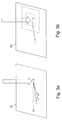
- FIG. 1is a schematic diagram of a practical application of a touch panel.
- FIG. 2is a schematic diagram of a touch panel implementing a method for determining a displacement of a touch point in accordance with an embodiment of the present invention.
- FIG. 3 ais a schematic diagram of a method for determining a displacement of a touch point according to the present invention when a plurality of touch points are simultaneously detected on a touch panel.
- FIG. 3 bis a schematic diagram of a plurality of reference displacements equivalent to an average displacement on a touch panel implementing a method for determining a displacement of a touch point according to the present invention.
- FIG. 4is a flow chart of a method for determining a displacement of a touch point in accordance with an embodiment of the present invention.
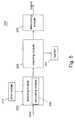
- FIG. 5is a block chart of an apparatus for determining a displacement of a touch point in accordance with an embodiment of the present invention.
- a touch panelIn common applications of a touch panel, it is first determined whether a touch is recognized as a touch point. Since the touch panel continuously scans sensors of the touch panel to detect which sensor is being touched (e.g., when a voltage of the sensor sensing the touch increases). With a scan frequency of the touch panel being tens of times per second, under normal operating conditions, the touch sensed by the sensor at the touched position is detected by several consecutive scans within a period during which the touch panel is pressed. More specifically, the touch is determined as a touch point only when the sensor corresponding to the touch point senses the touch for a predetermined period during scanning or by a predetermined number of times of scans. On the contrary, when the sensor on the touch panel only senses the touch in certain scans with the touched time not exceeding the predetermined period, the touch panel does not regard the position sensed by the sensor as a touch point.
- FIG. 1shows a schematic diagram of a practical application of a touch panel 10 .
- the touch panel 10detects a corresponding touch point according to an electric signal change corresponding to the touch.
- a movement path ABcorresponding to the touch points A and B is generated.
- a corresponding electric signal generated by the touch panel 10is transmitted to a system that performs an operation corresponding to the movement of the finger of the user or the touch pen, e.g., the operation is to move a cursor on a screen.
- Errorsmay occur in the determination of a touch point movement due to a touch strength, a hand tremor, a sensitivity of the touch panel 10 or circuit surges caused by EMI.
- a touch point movement between two touch pointsis limited by a physical limitation of a motion of a human finger. Therefore, a displacement valid interval is defined in a reasonable range to determine whether the touch point movement is valid when the touch panel 10 is under normal operations.
- FIG. 2shows a schematic diagram of a touch panel implementing a method for determining a touch point displacement in accordance with an embodiment of the present invention.
- a touch point Ais generated by a user touching a touch panel 20 .
- the usermoves the touch point towards a direction of the arrow in FIG. 2 to generate a displacement corresponding to the movement of the touch point.
- the touch pointis moved to a position C, D or E shown in FIG. 2 to generate a displacement AC, AD or AE.
- two limit rangesare determined by a first predetermined value and a second predetermined value, e.g., a lower limit range 30 is determined according to the first predetermined value and an upper limit range 40 is determined according to the second predetermined value.
- a predetermined range from the lower limit range 30 to the upper limit range 40is a valid interval.
- the touch point displacementis within the predetermined range (i.e., the displacement is greater than the first predetermined value and is smaller than the second predetermined value, e.g., the displacement AD in FIG. 2 )
- the touch point displacementis not within the predetermined range (i.e., the displacement is smaller than the first predetermined value or is greater than the second predetermined value, e.g., the displacement AC or AE in FIG. 2 )
- the displacement of the touch pointis discarded and the system does not perform any operation.
- the first predetermined value and the second predetermined valueare determined according to possible valid movements generated by using the touch panel under normal operations, and are varied according to factors such as a size or sensitivity of the touch panel.
- the first predetermined value and the second predetermined valuemay be defined by a designer before leaving the factory, user-defined, or defined according to usage habits of the user by implementing an auto-learning mechanism designed by software.
- the situation that the displacement of a touch point is smaller than the first predetermined valueis caused by manual operations such as a hand tremor; the situation that the touch point movement is greater than the second predetermined value (e.g. the displacement AE in FIG. 2 ) is generated due to a system misjudge caused by EMI.
- the method for determining a displacement of a touch point and an associated apparatus according to the present inventionare especially effective in preventing system misjudges caused by EMI.
- the first predetermined value and the second predetermined valueare standardized to be applied to touch panels of all types of specifications.
- the displacementis accordingly adjusted to be compared with the first predetermined value and the second predetermined value to determine whether the movement is valid. For example, suppose a diagonal distance of the touch panel is specified as 1 and the first and second predetermined values are specified as numbers between 0 to 1.
- the first predetermined value, the second predetermined value and the displacementare restored with respect to an actual diagonal distance of the touch panel when such specification is applied to touch panels of different sizes.
- the diagonal distance of the touch panel used in the normalizing calculationis discussed for illustration purposes, and a length or a width of the touch panel may also be applied to the normalizing calculation.
- the normalizing calculationis not the only calculation approach, but other calculation approaches may also be adopted according to actual requirements.
- the calculation approaches with respect to the first predetermined value and the second predetermined valueneed not be identical to that with respect to the displacement.
- two coordinate axis directions of 2D coordinatesare analyzed, e.g., the displacement of a touch point can be divided into two components in the two coordinate axis directions, and the two components are then analyzed, e.g., a first predetermined value and a second predetermined value are defined in a first coordinate axis direction.
- the component of the displacement in the first coordinate axis directionis compared with the first predetermined value and the second predetermined value
- the component of the displacement in a second coordinate axis directionis compared with a third predetermined value and a fourth predetermined value, so as to generate two comparison results.
- the displacementscorrespond to valid touch point movements in the two coordinate axis directions. More specifically, when the component of the displacement is greater than the first predetermined value and is smaller than the second predetermined value, it is determined that the movement is valid in the first coordinate axis direction; and when the component of the displacement is greater than the third predetermined value and is smaller than the fourth predetermined value, it is determined that the movement is valid in the second coordinate axis direction.
- a time intervalcan be defined, with a touch point detected by the touch panel at a start point of the time interval being regarded as a first touch point, and a touch point detected by the touch panel at an end point of the time interval being regarded as a second touch point.
- a displacementis a distance from the first touch point to the second touch point.
- a point A of the arrowrepresents a position of a touch point detected by a touch panel 20 at a start point of a time interval.
- touch signalsare detected in different areas on the touch panel 20 supposing the touch panel 20 is interfered with by noise.
- FIG. 4shows a flow chart of a method for determining a displacement of a touch point in accordance with an embodiment of the present invention.
- touch pointsare considered as being already formed, i.e., the step of determining whether a touch is valid is omitted. The method is described below.
- Step 100a touch point on the touch panel is detected.
- Step 110it is determined whether the touch is valid. When the answer of Step 110 is positive, Step 115 is performed; otherwise, Step 160 is performed.
- Step 115a position of the touch detected on the touch panel is recorded as a start touch point.
- Step 120it is determined whether another valid touch is detected on the touch panel. When the answer of Step 120 is positive, Step 125 is performed; otherwise, Step 160 is performed.
- Step 125it is determined whether a plurality of touch points are simultaneously detected on the touch panel.
- Step 145is performed; otherwise, Step 130 in which a displacement is obtained by calculating a displacement between two touch points is performed.
- Step 135the displacement is compared with a first predetermined value and a second predetermined value.
- Step 155is performed; when the displacement is smaller than the first predetermined value and is greater than the second predetermined value, Step 140 is performed.
- Step 140it is determined that the movement is invalid, and the displacement is discarded and the flow returns to Step 120 .
- Step 145a plurality of reference displacements between the start touch point and the plurality of touch points are calculated, and the flow continues to Step 150 .
- Step 150the plurality of reference displacements are averaged to obtain a displacement, and the flow returns to Step 135 .
- Step 155the movement is valid, and the system is informed to perform an operation corresponding to the movement.
- Step 160the flow ends.
- an apparatus for determining a touch point displacementis capable of reducing noises that interferer with the determination of the touch point displacement.
- FIG. 5shows a block diagram of an apparatus for determining a displacement of a touch point in accordance with an embodiment of the present invention.
- An apparatus 200 for determining a displacement of a touch pointcomprises a time module 210 , a detecting module 220 , a checking module 240 , a determining module 250 , and a register 260 .
- the detecting module 220comprises a calculating module 230 .
- touch pointsare considered as being already formed, i.e., the step of determining whether a touch is valid is omitted.
- a sensor of the touch panelfirst senses a touch point being generated and an area of the touch point, and transmits the sensed result to the detecting module 220 .
- the time module 210generates a time signal, e.g., a clock signal, and the detecting module 220 determines a time interval according to the time signal.
- the detecting module 220detects a start position of a touch point on the touch panel, and detects an end position of the touch point on the touch panel at the end point of the time interval to generate a displacement.
- the calculating module 230 of the detecting moduleWhen positions of a plurality of touch points are detected on the touch panel at the end point of the time interval, the calculating module 230 of the detecting module performs a mathematic calculation on the plurality of positions, e.g., an average calculation, to obtain the displacement. In another embodiment, the calculating module 230 of the detecting module 220 can perform another mathematic calculation, e.g., a normalizing calculation, to obtain a displacement. After that, the checking module 240 compares the displacement with a first predetermined value and a second predetermined value stored in the register 260 to check whether the displacement is within a predetermined range, so as to generate a check result to be transmitted to the determining module 250 .
- a mathematic calculationon the plurality of positions
- the calculating module 230 of the detecting module 220can perform another mathematic calculation, e.g., a normalizing calculation, to obtain a displacement.
- the checking module 240compares the displacement with a first
- the determining module 250determines that the movement is valid and transmits a signal to the system; when the check result indicates that the displacement is smaller than the first predetermined value or is greater than the second predetermined value, the determining module 250 determines that the movement is not valid and discards the displacement.
- the apparatus for determining a touch point displacement according to the present inventionmay be realized by a hardware structure, e.g., physical electronic circuits.
- functions of the modulesmay be realized by software or firmware approaches, and other approaches apparent to a person having ordinary skills in the art shall not be described for brevity.
Landscapes
- Engineering & Computer Science (AREA)
- General Engineering & Computer Science (AREA)
- Theoretical Computer Science (AREA)
- Human Computer Interaction (AREA)
- Physics & Mathematics (AREA)
- General Physics & Mathematics (AREA)
- Position Input By Displaying (AREA)
- User Interface Of Digital Computer (AREA)
Abstract
Description
Claims (14)
Applications Claiming Priority (3)
| Application Number | Priority Date | Filing Date | Title |
|---|---|---|---|
| TW098125778 | 2009-07-31 | ||
| TW98125778A | 2009-07-31 | ||
| TW098125778ATWI484380B (en) | 2009-07-31 | 2009-07-31 | Determinative method and device of touch point movement |
Publications (2)
| Publication Number | Publication Date |
|---|---|
| US20110025628A1 US20110025628A1 (en) | 2011-02-03 |
| US8994697B2true US8994697B2 (en) | 2015-03-31 |
Family
ID=43526532
Family Applications (1)
| Application Number | Title | Priority Date | Filing Date |
|---|---|---|---|
| US12/844,049Expired - Fee RelatedUS8994697B2 (en) | 2009-07-31 | 2010-07-27 | Method for determining touch point displacement and associated apparatus |
Country Status (2)
| Country | Link |
|---|---|
| US (1) | US8994697B2 (en) |
| TW (1) | TWI484380B (en) |
Cited By (9)
| Publication number | Priority date | Publication date | Assignee | Title |
|---|---|---|---|---|
| US20120304131A1 (en)* | 2011-05-27 | 2012-11-29 | Jennifer Nan | Edge gesture |
| US9229918B2 (en) | 2010-12-23 | 2016-01-05 | Microsoft Technology Licensing, Llc | Presenting an application change through a tile |
| US9329774B2 (en) | 2011-05-27 | 2016-05-03 | Microsoft Technology Licensing, Llc | Switching back to a previously-interacted-with application |
| US9535597B2 (en) | 2011-05-27 | 2017-01-03 | Microsoft Technology Licensing, Llc | Managing an immersive interface in a multi-application immersive environment |
| US9658766B2 (en) | 2011-05-27 | 2017-05-23 | Microsoft Technology Licensing, Llc | Edge gesture |
| US10254955B2 (en) | 2011-09-10 | 2019-04-09 | Microsoft Technology Licensing, Llc | Progressively indicating new content in an application-selectable user interface |
| US10303325B2 (en) | 2011-05-27 | 2019-05-28 | Microsoft Technology Licensing, Llc | Multi-application environment |
| US10579250B2 (en) | 2011-09-01 | 2020-03-03 | Microsoft Technology Licensing, Llc | Arranging tiles |
| US10969944B2 (en) | 2010-12-23 | 2021-04-06 | Microsoft Technology Licensing, Llc | Application reporting in an application-selectable user interface |
Families Citing this family (16)
| Publication number | Priority date | Publication date | Assignee | Title |
|---|---|---|---|---|
| US8810529B2 (en)* | 2011-02-11 | 2014-08-19 | Blackberry Limited | Electronic device and method of controlling same |
| CN102650912A (en)* | 2011-02-23 | 2012-08-29 | 安国国际科技股份有限公司 | Signal processing method and system of touch panel |
| RU2472207C1 (en)* | 2011-08-04 | 2013-01-10 | Павел Алексеевич Манахов | Method of inputting data using touch-sensitive surface, for example, touchpad or touch screen |
| US8803825B2 (en)* | 2011-09-27 | 2014-08-12 | Carefusion 303, Inc. | System and method for filtering touch screen inputs |
| JP6103807B2 (en)* | 2012-01-10 | 2017-03-29 | キヤノン株式会社 | Display control apparatus, control method thereof, and program |
| JP5958059B2 (en)* | 2012-05-09 | 2016-07-27 | コニカミノルタ株式会社 | Flick operation accepting device, flick operation accepting method, and flick operation accepting program |
| KR20130138880A (en)* | 2012-06-11 | 2013-12-20 | 삼성전자주식회사 | Method and apparatus for controlling a input in a terminal equipment having a touch input device |
| TWI480786B (en)* | 2012-06-26 | 2015-04-11 | Himax Tech Ltd | Touch device and touch point detecting method thereof |
| US9262010B2 (en) | 2012-09-05 | 2016-02-16 | Synaptics Incorporated | Systems and methods for reducing effects of interference in input devices |
| CN102890586B (en)* | 2012-10-08 | 2016-09-07 | 广东欧珀移动通信有限公司 | A kind of touch-screen anti-interference method and terminal device thereof |
| US20150338960A1 (en)* | 2013-01-09 | 2015-11-26 | Sharp Kabushiki Kaisha | Touch panel system |
| JP2014174801A (en)* | 2013-03-11 | 2014-09-22 | Sony Corp | Information processing apparatus, information processing method and program |
| US8922516B2 (en)* | 2013-03-27 | 2014-12-30 | Tianjin Funayuanchuang Technology Co., Ltd. | Touch panel and multi-points detecting method |
| JP6369805B2 (en)* | 2013-12-24 | 2018-08-08 | Tianma Japan株式会社 | Touch sensor device, electronic device, and touch gesture detection program |
| CN105320316B (en)* | 2014-06-17 | 2020-12-11 | 中兴通讯股份有限公司 | Method and device for removing jitter of touch screen and terminal |
| TWI800307B (en)* | 2022-03-17 | 2023-04-21 | 元太科技工業股份有限公司 | Inspection tool and inspection method for a touch plate |
Citations (42)
| Publication number | Priority date | Publication date | Assignee | Title |
|---|---|---|---|---|
| US5543591A (en) | 1992-06-08 | 1996-08-06 | Synaptics, Incorporated | Object position detector with edge motion feature and gesture recognition |
| US5825352A (en) | 1996-01-04 | 1998-10-20 | Logitech, Inc. | Multiple fingers contact sensing method for emulating mouse buttons and mouse operations on a touch sensor pad |
| US5880411A (en) | 1992-06-08 | 1999-03-09 | Synaptics, Incorporated | Object position detector with edge motion feature and gesture recognition |
| US5943052A (en) | 1997-08-12 | 1999-08-24 | Synaptics, Incorporated | Method and apparatus for scroll bar control |
| US6366866B1 (en)* | 1998-01-27 | 2002-04-02 | Sanyo Electric Co., Ltd. | Coordinates detecting apparatus for independently correcting coordinates |
| US20040196269A1 (en)* | 2000-09-29 | 2004-10-07 | Dotson Gary Dan | Low power dissipation touch plane interface circuit |
| US20050162404A1 (en) | 2004-01-08 | 2005-07-28 | Yen-Chang Chiu | Apparatus with one or more capacitive touchpads as interface |
| US20050179672A1 (en) | 2004-02-17 | 2005-08-18 | Yen-Chang Chiu | Simplified capacitive touchpad and method thereof |
| US20050259086A1 (en) | 2004-05-20 | 2005-11-24 | Yen-Chang Chiu | Capacitive touchpad integrated with a graphical input function |
| US20060026536A1 (en) | 2004-07-30 | 2006-02-02 | Apple Computer, Inc. | Gestures for touch sensitive input devices |
| US20060022956A1 (en) | 2003-09-02 | 2006-02-02 | Apple Computer, Inc. | Touch-sensitive electronic apparatus for media applications, and methods therefor |
| US20060033722A1 (en) | 2004-08-13 | 2006-02-16 | Yen-Chang Chiu | Structure and mechanism for power-saving of a capacitive touchpad |
| US20060038796A1 (en)* | 2001-08-29 | 2006-02-23 | Microsoft Corporation | Enhanced scrolling |
| US20060066590A1 (en)* | 2004-09-29 | 2006-03-30 | Masanori Ozawa | Input device |
| US20060125801A1 (en) | 2004-12-14 | 2006-06-15 | Chao-Hui Hsu | Capacitive touchpad having dual traces coupled with uneven spaced interlaced sensors |
| US20060232563A1 (en) | 2005-04-19 | 2006-10-19 | Jia-Yih Lii | Touch-sense apparatus available for one-dimensional and two-dimensional modes and control method therefor |
| US20060232559A1 (en) | 2005-04-19 | 2006-10-19 | Yung-Lieh Chien | Capacitive touchpad with physical key function |
| US20060279550A1 (en) | 2005-06-13 | 2006-12-14 | Jia-Yih Lii | Integrally formed touchpad module |
| US20060279551A1 (en) | 2005-06-08 | 2006-12-14 | Jia-Yih Lii | Method for object detection on a capacitive touchpad |
| US20070008295A1 (en) | 2005-07-08 | 2007-01-11 | Yung-Lieh Chien | Method for gesture detection on a touchpad |
| US20070013670A1 (en) | 2005-07-12 | 2007-01-18 | Yung-Lieh Chien | Method for gesture detection on a touchpad |
| US20070013669A1 (en) | 2005-07-12 | 2007-01-18 | Yung-Lieh Chien | Method for gesture detection on a touchpad |
| US20070046648A1 (en) | 2005-08-31 | 2007-03-01 | Wen-Kai Lee | Touch sensor having compensated base capacitance |
| US20070070049A1 (en) | 2005-09-23 | 2007-03-29 | Wen-Kai Lee | Base capacitance compensation for a touchpad sensor |
| US20070070044A1 (en) | 2005-09-23 | 2007-03-29 | Elan Microelectronics Corp. | Key touchpad module |
| US20070075984A1 (en) | 2005-10-04 | 2007-04-05 | Yen-Chang Chiu | Method and device for scroll bar control on a touchpad having programmed sections |
| US20070075983A1 (en) | 2005-10-04 | 2007-04-05 | Yen-Chang Chiu | Method for gesture detection on a touchpad |
| US20070080953A1 (en) | 2005-10-07 | 2007-04-12 | Jia-Yih Lii | Method for window movement control on a touchpad having a touch-sense defined speed |
| US20070091077A1 (en) | 2005-10-25 | 2007-04-26 | Jia-Yih Lii | Method for gesture detection on a capacitive touchpad |
| US20070091075A1 (en) | 2005-10-25 | 2007-04-26 | Jia-Yih Lii | Method for window operation on a touchpad using a touch defined original point |
| US20070126708A1 (en) | 2005-12-05 | 2007-06-07 | Tso-Chieh Yang | Method for gesture detection on a touch control bar with button and scroll bar functions |
| US20070132741A1 (en) | 2005-12-14 | 2007-06-14 | Yen-Chang Chiu | Movement detection method for multiple objects on a capacitive touchpad |
| US20070165005A1 (en) | 2005-06-08 | 2007-07-19 | Jia-Yih Lii | Method for multiple objects detection on a capacitive touchpad |
| US20070185631A1 (en) | 2006-02-09 | 2007-08-09 | Elan Microelectronics Corp. | Multi-functional touchpad controller for automobile |
| US7274353B2 (en) | 2003-04-02 | 2007-09-25 | Elan Microelectronics Corporation | Capacitive touchpad integrated with key and handwriting functions |
| US20080106524A1 (en) | 2004-07-05 | 2008-05-08 | Yen-Chang Chiu | Method for scroll bar control on a touchpad |
| US20080150715A1 (en) | 2006-12-21 | 2008-06-26 | Elan Microelectronics Corporation | Operation control methods and systems |
| CN101295220A (en) | 2004-01-07 | 2008-10-29 | 仁宝电脑工业股份有限公司 | Signal processing method of resistance type touch control panel |
| CN101398739A (en) | 2007-09-25 | 2009-04-01 | 博思天地(北京)科技有限公司 | Page browsing method, device based on touch screen and mobile communication terminal thereof |
| US20090217211A1 (en)* | 2008-02-27 | 2009-08-27 | Gesturetek, Inc. | Enhanced input using recognized gestures |
| US20100020029A1 (en)* | 2008-07-28 | 2010-01-28 | Samsung Electronics Co., Ltd. | Touch screen display device and driving method of the same |
| US20120044150A1 (en)* | 2009-04-24 | 2012-02-23 | Cypress Semiconductor Corporation | Touch Identification for Multi-Touch Technology |
- 2009
- 2009-07-31TWTW098125778Apatent/TWI484380B/ennot_activeIP Right Cessation
- 2010
- 2010-07-27USUS12/844,049patent/US8994697B2/ennot_activeExpired - Fee Related
Patent Citations (45)
| Publication number | Priority date | Publication date | Assignee | Title |
|---|---|---|---|---|
| US5880411A (en) | 1992-06-08 | 1999-03-09 | Synaptics, Incorporated | Object position detector with edge motion feature and gesture recognition |
| US6380931B1 (en) | 1992-06-08 | 2002-04-30 | Synaptics Incorporated | Object position detector with edge motion feature and gesture recognition |
| US5543591A (en) | 1992-06-08 | 1996-08-06 | Synaptics, Incorporated | Object position detector with edge motion feature and gesture recognition |
| US5825352A (en) | 1996-01-04 | 1998-10-20 | Logitech, Inc. | Multiple fingers contact sensing method for emulating mouse buttons and mouse operations on a touch sensor pad |
| US5943052A (en) | 1997-08-12 | 1999-08-24 | Synaptics, Incorporated | Method and apparatus for scroll bar control |
| US6366866B1 (en)* | 1998-01-27 | 2002-04-02 | Sanyo Electric Co., Ltd. | Coordinates detecting apparatus for independently correcting coordinates |
| US20040196269A1 (en)* | 2000-09-29 | 2004-10-07 | Dotson Gary Dan | Low power dissipation touch plane interface circuit |
| US20060038796A1 (en)* | 2001-08-29 | 2006-02-23 | Microsoft Corporation | Enhanced scrolling |
| US7274353B2 (en) | 2003-04-02 | 2007-09-25 | Elan Microelectronics Corporation | Capacitive touchpad integrated with key and handwriting functions |
| US20060022956A1 (en) | 2003-09-02 | 2006-02-02 | Apple Computer, Inc. | Touch-sensitive electronic apparatus for media applications, and methods therefor |
| CN101295220A (en) | 2004-01-07 | 2008-10-29 | 仁宝电脑工业股份有限公司 | Signal processing method of resistance type touch control panel |
| US20050162404A1 (en) | 2004-01-08 | 2005-07-28 | Yen-Chang Chiu | Apparatus with one or more capacitive touchpads as interface |
| US20050179672A1 (en) | 2004-02-17 | 2005-08-18 | Yen-Chang Chiu | Simplified capacitive touchpad and method thereof |
| US20050259086A1 (en) | 2004-05-20 | 2005-11-24 | Yen-Chang Chiu | Capacitive touchpad integrated with a graphical input function |
| US20080106524A1 (en) | 2004-07-05 | 2008-05-08 | Yen-Chang Chiu | Method for scroll bar control on a touchpad |
| US20060026535A1 (en) | 2004-07-30 | 2006-02-02 | Apple Computer Inc. | Mode-based graphical user interfaces for touch sensitive input devices |
| US20060026521A1 (en) | 2004-07-30 | 2006-02-02 | Apple Computer, Inc. | Gestures for touch sensitive input devices |
| US20060026536A1 (en) | 2004-07-30 | 2006-02-02 | Apple Computer, Inc. | Gestures for touch sensitive input devices |
| US20060033722A1 (en) | 2004-08-13 | 2006-02-16 | Yen-Chang Chiu | Structure and mechanism for power-saving of a capacitive touchpad |
| US20060066590A1 (en)* | 2004-09-29 | 2006-03-30 | Masanori Ozawa | Input device |
| US20060125801A1 (en) | 2004-12-14 | 2006-06-15 | Chao-Hui Hsu | Capacitive touchpad having dual traces coupled with uneven spaced interlaced sensors |
| US20060232559A1 (en) | 2005-04-19 | 2006-10-19 | Yung-Lieh Chien | Capacitive touchpad with physical key function |
| US20060232563A1 (en) | 2005-04-19 | 2006-10-19 | Jia-Yih Lii | Touch-sense apparatus available for one-dimensional and two-dimensional modes and control method therefor |
| US20060279551A1 (en) | 2005-06-08 | 2006-12-14 | Jia-Yih Lii | Method for object detection on a capacitive touchpad |
| US20070165005A1 (en) | 2005-06-08 | 2007-07-19 | Jia-Yih Lii | Method for multiple objects detection on a capacitive touchpad |
| US20060279550A1 (en) | 2005-06-13 | 2006-12-14 | Jia-Yih Lii | Integrally formed touchpad module |
| US20070008295A1 (en) | 2005-07-08 | 2007-01-11 | Yung-Lieh Chien | Method for gesture detection on a touchpad |
| US20070013670A1 (en) | 2005-07-12 | 2007-01-18 | Yung-Lieh Chien | Method for gesture detection on a touchpad |
| US20070013669A1 (en) | 2005-07-12 | 2007-01-18 | Yung-Lieh Chien | Method for gesture detection on a touchpad |
| US20070046648A1 (en) | 2005-08-31 | 2007-03-01 | Wen-Kai Lee | Touch sensor having compensated base capacitance |
| US20070070049A1 (en) | 2005-09-23 | 2007-03-29 | Wen-Kai Lee | Base capacitance compensation for a touchpad sensor |
| US20070070044A1 (en) | 2005-09-23 | 2007-03-29 | Elan Microelectronics Corp. | Key touchpad module |
| US20070075984A1 (en) | 2005-10-04 | 2007-04-05 | Yen-Chang Chiu | Method and device for scroll bar control on a touchpad having programmed sections |
| US20070075983A1 (en) | 2005-10-04 | 2007-04-05 | Yen-Chang Chiu | Method for gesture detection on a touchpad |
| US20070080953A1 (en) | 2005-10-07 | 2007-04-12 | Jia-Yih Lii | Method for window movement control on a touchpad having a touch-sense defined speed |
| US20070091077A1 (en) | 2005-10-25 | 2007-04-26 | Jia-Yih Lii | Method for gesture detection on a capacitive touchpad |
| US20070091075A1 (en) | 2005-10-25 | 2007-04-26 | Jia-Yih Lii | Method for window operation on a touchpad using a touch defined original point |
| US20070126708A1 (en) | 2005-12-05 | 2007-06-07 | Tso-Chieh Yang | Method for gesture detection on a touch control bar with button and scroll bar functions |
| US20070132741A1 (en) | 2005-12-14 | 2007-06-14 | Yen-Chang Chiu | Movement detection method for multiple objects on a capacitive touchpad |
| US20070185631A1 (en) | 2006-02-09 | 2007-08-09 | Elan Microelectronics Corp. | Multi-functional touchpad controller for automobile |
| US20080150715A1 (en) | 2006-12-21 | 2008-06-26 | Elan Microelectronics Corporation | Operation control methods and systems |
| CN101398739A (en) | 2007-09-25 | 2009-04-01 | 博思天地(北京)科技有限公司 | Page browsing method, device based on touch screen and mobile communication terminal thereof |
| US20090217211A1 (en)* | 2008-02-27 | 2009-08-27 | Gesturetek, Inc. | Enhanced input using recognized gestures |
| US20100020029A1 (en)* | 2008-07-28 | 2010-01-28 | Samsung Electronics Co., Ltd. | Touch screen display device and driving method of the same |
| US20120044150A1 (en)* | 2009-04-24 | 2012-02-23 | Cypress Semiconductor Corporation | Touch Identification for Multi-Touch Technology |
Cited By (11)
| Publication number | Priority date | Publication date | Assignee | Title |
|---|---|---|---|---|
| US9229918B2 (en) | 2010-12-23 | 2016-01-05 | Microsoft Technology Licensing, Llc | Presenting an application change through a tile |
| US10969944B2 (en) | 2010-12-23 | 2021-04-06 | Microsoft Technology Licensing, Llc | Application reporting in an application-selectable user interface |
| US11126333B2 (en) | 2010-12-23 | 2021-09-21 | Microsoft Technology Licensing, Llc | Application reporting in an application-selectable user interface |
| US20120304131A1 (en)* | 2011-05-27 | 2012-11-29 | Jennifer Nan | Edge gesture |
| US9329774B2 (en) | 2011-05-27 | 2016-05-03 | Microsoft Technology Licensing, Llc | Switching back to a previously-interacted-with application |
| US9535597B2 (en) | 2011-05-27 | 2017-01-03 | Microsoft Technology Licensing, Llc | Managing an immersive interface in a multi-application immersive environment |
| US9658766B2 (en) | 2011-05-27 | 2017-05-23 | Microsoft Technology Licensing, Llc | Edge gesture |
| US10303325B2 (en) | 2011-05-27 | 2019-05-28 | Microsoft Technology Licensing, Llc | Multi-application environment |
| US11698721B2 (en) | 2011-05-27 | 2023-07-11 | Microsoft Technology Licensing, Llc | Managing an immersive interface in a multi-application immersive environment |
| US10579250B2 (en) | 2011-09-01 | 2020-03-03 | Microsoft Technology Licensing, Llc | Arranging tiles |
| US10254955B2 (en) | 2011-09-10 | 2019-04-09 | Microsoft Technology Licensing, Llc | Progressively indicating new content in an application-selectable user interface |
Also Published As
| Publication number | Publication date |
|---|---|
| US20110025628A1 (en) | 2011-02-03 |
| TWI484380B (en) | 2015-05-11 |
| TW201104525A (en) | 2011-02-01 |
Similar Documents
| Publication | Publication Date | Title |
|---|---|---|
| US8994697B2 (en) | Method for determining touch point displacement and associated apparatus | |
| US9128603B2 (en) | Hand gesture recognition method for touch panel and associated apparatus | |
| US8482536B1 (en) | Compensation of signal values for a touch sensor | |
| US8917257B2 (en) | Coordinate detecting device and coordinate detecting program | |
| US9310927B2 (en) | Touch identification for multi-touch technology | |
| US9448667B2 (en) | Coordinate detecting device | |
| US8810543B1 (en) | All points addressable touch sensing surface | |
| TWI398807B (en) | Posistion apparatus for touch device and posistion method thereof | |
| US20140285469A1 (en) | Predictive Touch Surface Scanning | |
| US8013842B2 (en) | Method for gesture detection on a capacitive touchpad | |
| US8692802B1 (en) | Method and apparatus for calculating coordinates with high noise immunity in touch applications | |
| US20110310064A1 (en) | User Interfaces and Associated Apparatus and Methods | |
| US8743061B2 (en) | Touch sensing method and electronic device | |
| WO2012067773A1 (en) | System and method for determining object information using an estimated deflection response | |
| US10228798B2 (en) | Detecting method of touch system for avoiding inadvertent touch | |
| US20110221695A1 (en) | Touch panel and touch sensing method thereof | |
| CN101727242B (en) | Method for sensing multiclutch on touch panel | |
| CN101950228B (en) | Touch point detection method | |
| WO2012129973A1 (en) | Method of identifying multi-touch scaling gesture and device using the same | |
| CN101526865B (en) | How the touchpad detects multiple touches | |
| US20090114457A1 (en) | Object detection for a capacitive ITO touchpad | |
| JP5814704B2 (en) | Touch panel controller, touch panel control method, input device using the same, and electronic device | |
| CN106371648A (en) | Calibration method and capacitive sensing device | |
| CN104185832A (en) | Touchscreen system | |
| CN102859473B (en) | Pointing position determination device and method, touch panel device, and electronic device |
Legal Events
| Date | Code | Title | Description |
|---|---|---|---|
| AS | Assignment | Owner name:MSTAR SEMICONDUCTOR, INC., TAIWAN Free format text:ASSIGNMENT OF ASSIGNORS INTEREST;ASSIGNORS:LIN, TSUNG-FU;WEN, CHAO-CHENG;SIGNING DATES FROM 20100525 TO 20100531;REEL/FRAME:024746/0030 | |
| STCF | Information on status: patent grant | Free format text:PATENTED CASE | |
| MAFP | Maintenance fee payment | Free format text:PAYMENT OF MAINTENANCE FEE, 4TH YEAR, LARGE ENTITY (ORIGINAL EVENT CODE: M1551); ENTITY STATUS OF PATENT OWNER: LARGE ENTITY Year of fee payment:4 | |
| AS | Assignment | Owner name:MEDIATEK INC., TAIWAN Free format text:MERGER;ASSIGNOR:MSTAR SEMICONDUCTOR, INC.;REEL/FRAME:050665/0001 Effective date:20190124 | |
| AS | Assignment | Owner name:XUESHAN TECHNOLOGIES INC., CANADA Free format text:ASSIGNMENT OF ASSIGNORS INTEREST;ASSIGNOR:MEDIATEK INC.;REEL/FRAME:055486/0870 Effective date:20201223 | |
| FEPP | Fee payment procedure | Free format text:MAINTENANCE FEE REMINDER MAILED (ORIGINAL EVENT CODE: REM.); ENTITY STATUS OF PATENT OWNER: LARGE ENTITY | |
| LAPS | Lapse for failure to pay maintenance fees | Free format text:PATENT EXPIRED FOR FAILURE TO PAY MAINTENANCE FEES (ORIGINAL EVENT CODE: EXP.); ENTITY STATUS OF PATENT OWNER: LARGE ENTITY | |
| STCH | Information on status: patent discontinuation | Free format text:PATENT EXPIRED DUE TO NONPAYMENT OF MAINTENANCE FEES UNDER 37 CFR 1.362 | |
| FP | Lapsed due to failure to pay maintenance fee | Effective date:20230331 |