US8992619B2 - Microstructured implant surfaces - Google Patents
Microstructured implant surfacesDownload PDFInfo
- Publication number
- US8992619B2 US8992619B2US13/286,813US201113286813AUS8992619B2US 8992619 B2US8992619 B2US 8992619B2US 201113286813 AUS201113286813 AUS 201113286813AUS 8992619 B2US8992619 B2US 8992619B2
- Authority
- US
- United States
- Prior art keywords
- surface pattern
- depth dimension
- bone
- implantable device
- implant
- Prior art date
- Legal status (The legal status is an assumption and is not a legal conclusion. Google has not performed a legal analysis and makes no representation as to the accuracy of the status listed.)
- Active, expires
Links
- 239000007943implantSubstances0.000titleabstractdescription113
- 239000000560biocompatible materialSubstances0.000claimsabstractdescription5
- 238000012876topographyMethods0.000claimsdescription48
- 210000000988bone and boneAnatomy0.000claimsdescription45
- 230000007774longtermEffects0.000claimsdescription9
- 210000000963osteoblastAnatomy0.000claimsdescription9
- 239000002105nanoparticleSubstances0.000claimsdescription7
- RTAQQCXQSZGOHL-UHFFFAOYSA-NTitaniumChemical compound[Ti]RTAQQCXQSZGOHL-UHFFFAOYSA-N0.000claimsdescription5
- 229910052719titaniumInorganic materials0.000claimsdescription5
- 239000010936titaniumSubstances0.000claimsdescription5
- 229910001069Ti alloyInorganic materials0.000claimsdescription4
- 230000035800maturationEffects0.000claimsdescription4
- 238000013461designMethods0.000claimsdescription3
- 230000000921morphogenic effectEffects0.000claimsdescription2
- 108090000623proteins and genesProteins0.000claimsdescription2
- 102000004169proteins and genesHuman genes0.000claimsdescription2
- 230000011664signalingEffects0.000claimsdescription2
- 238000000034methodMethods0.000abstractdescription35
- 208000015122neurodegenerative diseaseDiseases0.000abstractdescription2
- 201000008482osteoarthritisDiseases0.000abstractdescription2
- 239000004696Poly ether ether ketoneSubstances0.000description14
- 229920002530polyetherether ketonePolymers0.000description14
- 230000008569processEffects0.000description14
- 239000000463materialSubstances0.000description13
- 238000011068loading methodMethods0.000description12
- 210000004027cellAnatomy0.000description11
- 230000004927fusionEffects0.000description9
- 230000000694effectsEffects0.000description8
- 238000003754machiningMethods0.000description8
- 238000004519manufacturing processMethods0.000description8
- 239000002253acidSubstances0.000description7
- 230000035876healingEffects0.000description7
- 238000012545processingMethods0.000description7
- 239000000126substanceSubstances0.000description7
- 230000008901benefitEffects0.000description6
- 238000005530etchingMethods0.000description5
- 230000006870functionEffects0.000description5
- 230000012010growthEffects0.000description5
- 230000010354integrationEffects0.000description5
- 230000001788irregularEffects0.000description5
- 230000035882stressEffects0.000description5
- 238000001356surgical procedureMethods0.000description5
- 210000001519tissueAnatomy0.000description5
- 102100024506Bone morphogenetic protein 2Human genes0.000description4
- 102100024505Bone morphogenetic protein 4Human genes0.000description4
- 101000762366Homo sapiens Bone morphogenetic protein 2Proteins0.000description4
- 101000762379Homo sapiens Bone morphogenetic protein 4Proteins0.000description4
- 230000036541healthEffects0.000description4
- 230000033001locomotionEffects0.000description4
- 230000036961partial effectEffects0.000description4
- 230000006641stabilisationEffects0.000description4
- 238000011105stabilizationMethods0.000description4
- 230000003746surface roughnessEffects0.000description4
- KRHYYFGTRYWZRS-UHFFFAOYSA-NFluoraneChemical compoundFKRHYYFGTRYWZRS-UHFFFAOYSA-N0.000description3
- 102000046299Transforming Growth Factor beta1Human genes0.000description3
- 101800002279Transforming growth factor beta-1Proteins0.000description3
- 230000006978adaptationEffects0.000description3
- 230000009286beneficial effectEffects0.000description3
- 238000005422blastingMethods0.000description3
- 230000001413cellular effectEffects0.000description3
- 238000003801millingMethods0.000description3
- 239000000203mixtureSubstances0.000description3
- 238000001259photo etchingMethods0.000description3
- 238000007634remodelingMethods0.000description3
- 230000008439repair processEffects0.000description3
- 230000000472traumatic effectEffects0.000description3
- 102000002260Alkaline PhosphataseHuman genes0.000description2
- 108020004774Alkaline PhosphataseProteins0.000description2
- 102100022544Bone morphogenetic protein 7Human genes0.000description2
- 101710169781Gremlin-1Proteins0.000description2
- 102100038367Gremlin-1Human genes0.000description2
- 101000899361Homo sapiens Bone morphogenetic protein 7Proteins0.000description2
- 102000004067OsteocalcinHuman genes0.000description2
- 108090000573OsteocalcinProteins0.000description2
- 102000008108OsteoprotegerinHuman genes0.000description2
- 108010035042OsteoprotegerinProteins0.000description2
- 208000002193PainDiseases0.000description2
- 238000011529RT qPCRMethods0.000description2
- 150000007513acidsChemical class0.000description2
- 238000004458analytical methodMethods0.000description2
- 238000004873anchoringMethods0.000description2
- 230000000975bioactive effectEffects0.000description2
- 230000004791biological behaviorEffects0.000description2
- 230000015572biosynthetic processEffects0.000description2
- 210000002449bone cellAnatomy0.000description2
- 230000008468bone growthEffects0.000description2
- 238000001311chemical methods and processMethods0.000description2
- 238000005516engineering processMethods0.000description2
- 230000014509gene expressionEffects0.000description2
- 210000001564haversian systemAnatomy0.000description2
- 238000002513implantationMethods0.000description2
- 238000001727in vivoMethods0.000description2
- 239000003112inhibitorSubstances0.000description2
- 238000009434installationMethods0.000description2
- 102000006495integrinsHuman genes0.000description2
- 108010044426integrinsProteins0.000description2
- 230000000873masking effectEffects0.000description2
- 238000001000micrographMethods0.000description2
- 230000005012migrationEffects0.000description2
- 238000013508migrationMethods0.000description2
- 230000004048modificationEffects0.000description2
- 238000012986modificationMethods0.000description2
- 102000045246nogginHuman genes0.000description2
- 108700007229nogginProteins0.000description2
- XXUPLYBCNPLTIW-UHFFFAOYSA-Noctadec-7-ynoic acidChemical compoundCCCCCCCCCCC#CCCCCCC(O)=OXXUPLYBCNPLTIW-UHFFFAOYSA-N0.000description2
- 230000002188osteogenic effectEffects0.000description2
- 238000002360preparation methodMethods0.000description2
- 238000001878scanning electron micrographMethods0.000description2
- 125000006850spacer groupChemical group0.000description2
- 230000000638stimulationEffects0.000description2
- 238000003466weldingMethods0.000description2
- 208000008035Back PainDiseases0.000description1
- 206010065687Bone lossDiseases0.000description1
- 208000017701Endocrine diseaseDiseases0.000description1
- 102100031181Glyceraldehyde-3-phosphate dehydrogenaseHuman genes0.000description1
- 101001046677Homo sapiens Integrin alpha-VProteins0.000description1
- 101000935043Homo sapiens Integrin beta-1Proteins0.000description1
- 102100022337Integrin alpha-VHuman genes0.000description1
- 102100025304Integrin beta-1Human genes0.000description1
- 206010061246Intervertebral disc degenerationDiseases0.000description1
- GRYLNZFGIOXLOG-UHFFFAOYSA-NNitric acidChemical compoundO[N+]([O-])=OGRYLNZFGIOXLOG-UHFFFAOYSA-N0.000description1
- 239000004793PolystyreneSubstances0.000description1
- 238000000692Student's t-testMethods0.000description1
- 238000005270abrasive blastingMethods0.000description1
- 239000006096absorbing agentSubstances0.000description1
- 230000032683agingEffects0.000description1
- 238000000540analysis of varianceMethods0.000description1
- 210000003423ankleAnatomy0.000description1
- 230000008512biological responseEffects0.000description1
- 210000002805bone matrixAnatomy0.000description1
- 239000013590bulk materialSubstances0.000description1
- 238000004113cell cultureMethods0.000description1
- 239000013592cell lysateSubstances0.000description1
- 230000036755cellular responseEffects0.000description1
- 210000003850cellular structureAnatomy0.000description1
- 239000000919ceramicSubstances0.000description1
- 238000007385chemical modificationMethods0.000description1
- 238000000576coating methodMethods0.000description1
- 239000003636conditioned culture mediumSubstances0.000description1
- 238000010276constructionMethods0.000description1
- 239000002537cosmeticSubstances0.000description1
- 230000001186cumulative effectEffects0.000description1
- 230000003412degenerative effectEffects0.000description1
- 210000004513dentitionAnatomy0.000description1
- 230000007783downstream signalingEffects0.000description1
- 238000005553drillingMethods0.000description1
- 208000030172endocrine system diseaseDiseases0.000description1
- 230000002708enhancing effectEffects0.000description1
- 210000002683footAnatomy0.000description1
- 108020004445glyceraldehyde-3-phosphate dehydrogenaseProteins0.000description1
- 230000007773growth patternEffects0.000description1
- 230000001771impaired effectEffects0.000description1
- 238000010348incorporationMethods0.000description1
- 238000007373indentationMethods0.000description1
- 230000002401inhibitory effectEffects0.000description1
- 208000014674injuryDiseases0.000description1
- 210000003127kneeAnatomy0.000description1
- 238000010329laser etchingMethods0.000description1
- 230000018984masticationEffects0.000description1
- 238000010077masticationMethods0.000description1
- 238000010297mechanical methods and processMethods0.000description1
- 230000005226mechanical processes and functionsEffects0.000description1
- 108020004999messenger RNAProteins0.000description1
- QPJSUIGXIBEQAC-UHFFFAOYSA-Nn-(2,4-dichloro-5-propan-2-yloxyphenyl)acetamideChemical compoundCC(C)OC1=CC(NC(C)=O)=C(Cl)C=C1ClQPJSUIGXIBEQAC-UHFFFAOYSA-N0.000description1
- 230000017074necrotic cell deathEffects0.000description1
- 229910017604nitric acidInorganic materials0.000description1
- 238000010899nucleationMethods0.000description1
- 238000005457optimizationMethods0.000description1
- 229920000620organic polymerPolymers0.000description1
- 230000000399orthopedic effectEffects0.000description1
- 230000011164ossificationEffects0.000description1
- 230000004072osteoblast differentiationEffects0.000description1
- 230000037361pathwayEffects0.000description1
- 238000001020plasma etchingMethods0.000description1
- 238000005498polishingMethods0.000description1
- 229920002223polystyrenePolymers0.000description1
- 238000012805post-processingMethods0.000description1
- 230000002980postoperative effectEffects0.000description1
- 230000035755proliferationEffects0.000description1
- 108020003175receptorsProteins0.000description1
- 102000005962receptorsHuman genes0.000description1
- 238000011084recoveryMethods0.000description1
- 230000002829reductive effectEffects0.000description1
- 238000007670refiningMethods0.000description1
- 230000001105regulatory effectEffects0.000description1
- 230000003252repetitive effectEffects0.000description1
- 230000004044responseEffects0.000description1
- 239000004576sandSubstances0.000description1
- 230000035939shockEffects0.000description1
- 238000005480shot peeningMethods0.000description1
- 210000004872soft tissueAnatomy0.000description1
- 239000007787solidSubstances0.000description1
- 230000004936stimulating effectEffects0.000description1
- 238000004381surface treatmentMethods0.000description1
- 238000011477surgical interventionMethods0.000description1
- 238000002560therapeutic procedureMethods0.000description1
- 230000036346tooth eruptionEffects0.000description1
- 230000008736traumatic injuryEffects0.000description1
Images


Classifications
- A—HUMAN NECESSITIES
- A61—MEDICAL OR VETERINARY SCIENCE; HYGIENE
- A61F—FILTERS IMPLANTABLE INTO BLOOD VESSELS; PROSTHESES; DEVICES PROVIDING PATENCY TO, OR PREVENTING COLLAPSING OF, TUBULAR STRUCTURES OF THE BODY, e.g. STENTS; ORTHOPAEDIC, NURSING OR CONTRACEPTIVE DEVICES; FOMENTATION; TREATMENT OR PROTECTION OF EYES OR EARS; BANDAGES, DRESSINGS OR ABSORBENT PADS; FIRST-AID KITS
- A61F2/00—Filters implantable into blood vessels; Prostheses, i.e. artificial substitutes or replacements for parts of the body; Appliances for connecting them with the body; Devices providing patency to, or preventing collapsing of, tubular structures of the body, e.g. stents
- A61F2/02—Prostheses implantable into the body
- A61F2/30—Joints
- A61F2/30767—Special external or bone-contacting surface, e.g. coating for improving bone ingrowth
- A—HUMAN NECESSITIES
- A61—MEDICAL OR VETERINARY SCIENCE; HYGIENE
- A61F—FILTERS IMPLANTABLE INTO BLOOD VESSELS; PROSTHESES; DEVICES PROVIDING PATENCY TO, OR PREVENTING COLLAPSING OF, TUBULAR STRUCTURES OF THE BODY, e.g. STENTS; ORTHOPAEDIC, NURSING OR CONTRACEPTIVE DEVICES; FOMENTATION; TREATMENT OR PROTECTION OF EYES OR EARS; BANDAGES, DRESSINGS OR ABSORBENT PADS; FIRST-AID KITS
- A61F2/00—Filters implantable into blood vessels; Prostheses, i.e. artificial substitutes or replacements for parts of the body; Appliances for connecting them with the body; Devices providing patency to, or preventing collapsing of, tubular structures of the body, e.g. stents
- A61F2/02—Prostheses implantable into the body
- A61F2/30—Joints
- A61F2/44—Joints for the spine, e.g. vertebrae, spinal discs
- A61F2/4455—Joints for the spine, e.g. vertebrae, spinal discs for the fusion of spinal bodies, e.g. intervertebral fusion of adjacent spinal bodies, e.g. fusion cages
- A61F2/4465—Joints for the spine, e.g. vertebrae, spinal discs for the fusion of spinal bodies, e.g. intervertebral fusion of adjacent spinal bodies, e.g. fusion cages having a circular or kidney shaped cross-section substantially perpendicular to the axis of the spine
- A—HUMAN NECESSITIES
- A61—MEDICAL OR VETERINARY SCIENCE; HYGIENE
- A61F—FILTERS IMPLANTABLE INTO BLOOD VESSELS; PROSTHESES; DEVICES PROVIDING PATENCY TO, OR PREVENTING COLLAPSING OF, TUBULAR STRUCTURES OF THE BODY, e.g. STENTS; ORTHOPAEDIC, NURSING OR CONTRACEPTIVE DEVICES; FOMENTATION; TREATMENT OR PROTECTION OF EYES OR EARS; BANDAGES, DRESSINGS OR ABSORBENT PADS; FIRST-AID KITS
- A61F2/00—Filters implantable into blood vessels; Prostheses, i.e. artificial substitutes or replacements for parts of the body; Appliances for connecting them with the body; Devices providing patency to, or preventing collapsing of, tubular structures of the body, e.g. stents
- A61F2/02—Prostheses implantable into the body
- A61F2/30—Joints
- A61F2/46—Special tools for implanting artificial joints
- A61F2/4603—Special tools for implanting artificial joints for insertion or extraction of endoprosthetic joints or of accessories thereof
- A61F2/4611—Special tools for implanting artificial joints for insertion or extraction of endoprosthetic joints or of accessories thereof of spinal prostheses
- A—HUMAN NECESSITIES
- A61—MEDICAL OR VETERINARY SCIENCE; HYGIENE
- A61F—FILTERS IMPLANTABLE INTO BLOOD VESSELS; PROSTHESES; DEVICES PROVIDING PATENCY TO, OR PREVENTING COLLAPSING OF, TUBULAR STRUCTURES OF THE BODY, e.g. STENTS; ORTHOPAEDIC, NURSING OR CONTRACEPTIVE DEVICES; FOMENTATION; TREATMENT OR PROTECTION OF EYES OR EARS; BANDAGES, DRESSINGS OR ABSORBENT PADS; FIRST-AID KITS
- A61F2/00—Filters implantable into blood vessels; Prostheses, i.e. artificial substitutes or replacements for parts of the body; Appliances for connecting them with the body; Devices providing patency to, or preventing collapsing of, tubular structures of the body, e.g. stents
- A61F2/02—Prostheses implantable into the body
- A61F2/28—Bones
- A61F2002/2817—Bone stimulation by chemical reactions or by osteogenic or biological products for enhancing ossification, e.g. by bone morphogenetic or morphogenic proteins [BMP] or by transforming growth factors [TGF]
- A—HUMAN NECESSITIES
- A61—MEDICAL OR VETERINARY SCIENCE; HYGIENE
- A61F—FILTERS IMPLANTABLE INTO BLOOD VESSELS; PROSTHESES; DEVICES PROVIDING PATENCY TO, OR PREVENTING COLLAPSING OF, TUBULAR STRUCTURES OF THE BODY, e.g. STENTS; ORTHOPAEDIC, NURSING OR CONTRACEPTIVE DEVICES; FOMENTATION; TREATMENT OR PROTECTION OF EYES OR EARS; BANDAGES, DRESSINGS OR ABSORBENT PADS; FIRST-AID KITS
- A61F2/00—Filters implantable into blood vessels; Prostheses, i.e. artificial substitutes or replacements for parts of the body; Appliances for connecting them with the body; Devices providing patency to, or preventing collapsing of, tubular structures of the body, e.g. stents
- A61F2/02—Prostheses implantable into the body
- A61F2/28—Bones
- A61F2002/2835—Bone graft implants for filling a bony defect or an endoprosthesis cavity, e.g. by synthetic material or biological material
- A—HUMAN NECESSITIES
- A61—MEDICAL OR VETERINARY SCIENCE; HYGIENE
- A61F—FILTERS IMPLANTABLE INTO BLOOD VESSELS; PROSTHESES; DEVICES PROVIDING PATENCY TO, OR PREVENTING COLLAPSING OF, TUBULAR STRUCTURES OF THE BODY, e.g. STENTS; ORTHOPAEDIC, NURSING OR CONTRACEPTIVE DEVICES; FOMENTATION; TREATMENT OR PROTECTION OF EYES OR EARS; BANDAGES, DRESSINGS OR ABSORBENT PADS; FIRST-AID KITS
- A61F2/00—Filters implantable into blood vessels; Prostheses, i.e. artificial substitutes or replacements for parts of the body; Appliances for connecting them with the body; Devices providing patency to, or preventing collapsing of, tubular structures of the body, e.g. stents
- A61F2/02—Prostheses implantable into the body
- A61F2/30—Joints
- A61F2002/30001—Additional features of subject-matter classified in A61F2/28, A61F2/30 and subgroups thereof
- A61F2002/30003—Material related properties of the prosthesis or of a coating on the prosthesis
- A61F2002/30004—Material related properties of the prosthesis or of a coating on the prosthesis the prosthesis being made from materials having different values of a given property at different locations within the same prosthesis
- A61F2002/30011—Material related properties of the prosthesis or of a coating on the prosthesis the prosthesis being made from materials having different values of a given property at different locations within the same prosthesis differing in porosity
- A61F2002/30013—
- A—HUMAN NECESSITIES
- A61—MEDICAL OR VETERINARY SCIENCE; HYGIENE
- A61F—FILTERS IMPLANTABLE INTO BLOOD VESSELS; PROSTHESES; DEVICES PROVIDING PATENCY TO, OR PREVENTING COLLAPSING OF, TUBULAR STRUCTURES OF THE BODY, e.g. STENTS; ORTHOPAEDIC, NURSING OR CONTRACEPTIVE DEVICES; FOMENTATION; TREATMENT OR PROTECTION OF EYES OR EARS; BANDAGES, DRESSINGS OR ABSORBENT PADS; FIRST-AID KITS
- A61F2/00—Filters implantable into blood vessels; Prostheses, i.e. artificial substitutes or replacements for parts of the body; Appliances for connecting them with the body; Devices providing patency to, or preventing collapsing of, tubular structures of the body, e.g. stents
- A61F2/02—Prostheses implantable into the body
- A61F2/30—Joints
- A61F2002/30001—Additional features of subject-matter classified in A61F2/28, A61F2/30 and subgroups thereof
- A61F2002/30316—The prosthesis having different structural features at different locations within the same prosthesis; Connections between prosthetic parts; Special structural features of bone or joint prostheses not otherwise provided for
- A61F2002/30317—The prosthesis having different structural features at different locations within the same prosthesis
- A61F2002/30321—The prosthesis having different structural features at different locations within the same prosthesis differing in roughness
- A—HUMAN NECESSITIES
- A61—MEDICAL OR VETERINARY SCIENCE; HYGIENE
- A61F—FILTERS IMPLANTABLE INTO BLOOD VESSELS; PROSTHESES; DEVICES PROVIDING PATENCY TO, OR PREVENTING COLLAPSING OF, TUBULAR STRUCTURES OF THE BODY, e.g. STENTS; ORTHOPAEDIC, NURSING OR CONTRACEPTIVE DEVICES; FOMENTATION; TREATMENT OR PROTECTION OF EYES OR EARS; BANDAGES, DRESSINGS OR ABSORBENT PADS; FIRST-AID KITS
- A61F2/00—Filters implantable into blood vessels; Prostheses, i.e. artificial substitutes or replacements for parts of the body; Appliances for connecting them with the body; Devices providing patency to, or preventing collapsing of, tubular structures of the body, e.g. stents
- A61F2/02—Prostheses implantable into the body
- A61F2/30—Joints
- A61F2002/30001—Additional features of subject-matter classified in A61F2/28, A61F2/30 and subgroups thereof
- A61F2002/30316—The prosthesis having different structural features at different locations within the same prosthesis; Connections between prosthetic parts; Special structural features of bone or joint prostheses not otherwise provided for
- A61F2002/30329—Connections or couplings between prosthetic parts, e.g. between modular parts; Connecting elements
- A61F2002/30451—Connections or couplings between prosthetic parts, e.g. between modular parts; Connecting elements soldered or brazed or welded
- A61F2002/30454—
- A—HUMAN NECESSITIES
- A61—MEDICAL OR VETERINARY SCIENCE; HYGIENE
- A61F—FILTERS IMPLANTABLE INTO BLOOD VESSELS; PROSTHESES; DEVICES PROVIDING PATENCY TO, OR PREVENTING COLLAPSING OF, TUBULAR STRUCTURES OF THE BODY, e.g. STENTS; ORTHOPAEDIC, NURSING OR CONTRACEPTIVE DEVICES; FOMENTATION; TREATMENT OR PROTECTION OF EYES OR EARS; BANDAGES, DRESSINGS OR ABSORBENT PADS; FIRST-AID KITS
- A61F2/00—Filters implantable into blood vessels; Prostheses, i.e. artificial substitutes or replacements for parts of the body; Appliances for connecting them with the body; Devices providing patency to, or preventing collapsing of, tubular structures of the body, e.g. stents
- A61F2/02—Prostheses implantable into the body
- A61F2/30—Joints
- A61F2002/30001—Additional features of subject-matter classified in A61F2/28, A61F2/30 and subgroups thereof
- A61F2002/30316—The prosthesis having different structural features at different locations within the same prosthesis; Connections between prosthetic parts; Special structural features of bone or joint prostheses not otherwise provided for
- A61F2002/30535—Special structural features of bone or joint prostheses not otherwise provided for
- A61F2002/30593—Special structural features of bone or joint prostheses not otherwise provided for hollow
- A—HUMAN NECESSITIES
- A61—MEDICAL OR VETERINARY SCIENCE; HYGIENE
- A61F—FILTERS IMPLANTABLE INTO BLOOD VESSELS; PROSTHESES; DEVICES PROVIDING PATENCY TO, OR PREVENTING COLLAPSING OF, TUBULAR STRUCTURES OF THE BODY, e.g. STENTS; ORTHOPAEDIC, NURSING OR CONTRACEPTIVE DEVICES; FOMENTATION; TREATMENT OR PROTECTION OF EYES OR EARS; BANDAGES, DRESSINGS OR ABSORBENT PADS; FIRST-AID KITS
- A61F2/00—Filters implantable into blood vessels; Prostheses, i.e. artificial substitutes or replacements for parts of the body; Appliances for connecting them with the body; Devices providing patency to, or preventing collapsing of, tubular structures of the body, e.g. stents
- A61F2/02—Prostheses implantable into the body
- A61F2/30—Joints
- A61F2/30767—Special external or bone-contacting surface, e.g. coating for improving bone ingrowth
- A61F2002/30769—Special external or bone-contacting surface, e.g. coating for improving bone ingrowth madreporic
- A—HUMAN NECESSITIES
- A61—MEDICAL OR VETERINARY SCIENCE; HYGIENE
- A61F—FILTERS IMPLANTABLE INTO BLOOD VESSELS; PROSTHESES; DEVICES PROVIDING PATENCY TO, OR PREVENTING COLLAPSING OF, TUBULAR STRUCTURES OF THE BODY, e.g. STENTS; ORTHOPAEDIC, NURSING OR CONTRACEPTIVE DEVICES; FOMENTATION; TREATMENT OR PROTECTION OF EYES OR EARS; BANDAGES, DRESSINGS OR ABSORBENT PADS; FIRST-AID KITS
- A61F2/00—Filters implantable into blood vessels; Prostheses, i.e. artificial substitutes or replacements for parts of the body; Appliances for connecting them with the body; Devices providing patency to, or preventing collapsing of, tubular structures of the body, e.g. stents
- A61F2/02—Prostheses implantable into the body
- A61F2/30—Joints
- A61F2/30767—Special external or bone-contacting surface, e.g. coating for improving bone ingrowth
- A61F2/30771—Special external or bone-contacting surface, e.g. coating for improving bone ingrowth applied in original prostheses, e.g. holes or grooves
- A61F2002/30772—Apertures or holes, e.g. of circular cross section
- A61F2002/30774—Apertures or holes, e.g. of circular cross section internally-threaded
- A—HUMAN NECESSITIES
- A61—MEDICAL OR VETERINARY SCIENCE; HYGIENE
- A61F—FILTERS IMPLANTABLE INTO BLOOD VESSELS; PROSTHESES; DEVICES PROVIDING PATENCY TO, OR PREVENTING COLLAPSING OF, TUBULAR STRUCTURES OF THE BODY, e.g. STENTS; ORTHOPAEDIC, NURSING OR CONTRACEPTIVE DEVICES; FOMENTATION; TREATMENT OR PROTECTION OF EYES OR EARS; BANDAGES, DRESSINGS OR ABSORBENT PADS; FIRST-AID KITS
- A61F2/00—Filters implantable into blood vessels; Prostheses, i.e. artificial substitutes or replacements for parts of the body; Appliances for connecting them with the body; Devices providing patency to, or preventing collapsing of, tubular structures of the body, e.g. stents
- A61F2/02—Prostheses implantable into the body
- A61F2/30—Joints
- A61F2/30767—Special external or bone-contacting surface, e.g. coating for improving bone ingrowth
- A61F2/30771—Special external or bone-contacting surface, e.g. coating for improving bone ingrowth applied in original prostheses, e.g. holes or grooves
- A61F2002/30772—Apertures or holes, e.g. of circular cross section
- A61F2002/30777—Oblong apertures
- A61F2002/30779—Oblong apertures arcuate
- A—HUMAN NECESSITIES
- A61—MEDICAL OR VETERINARY SCIENCE; HYGIENE
- A61F—FILTERS IMPLANTABLE INTO BLOOD VESSELS; PROSTHESES; DEVICES PROVIDING PATENCY TO, OR PREVENTING COLLAPSING OF, TUBULAR STRUCTURES OF THE BODY, e.g. STENTS; ORTHOPAEDIC, NURSING OR CONTRACEPTIVE DEVICES; FOMENTATION; TREATMENT OR PROTECTION OF EYES OR EARS; BANDAGES, DRESSINGS OR ABSORBENT PADS; FIRST-AID KITS
- A61F2/00—Filters implantable into blood vessels; Prostheses, i.e. artificial substitutes or replacements for parts of the body; Appliances for connecting them with the body; Devices providing patency to, or preventing collapsing of, tubular structures of the body, e.g. stents
- A61F2/02—Prostheses implantable into the body
- A61F2/30—Joints
- A61F2/30767—Special external or bone-contacting surface, e.g. coating for improving bone ingrowth
- A61F2/30771—Special external or bone-contacting surface, e.g. coating for improving bone ingrowth applied in original prostheses, e.g. holes or grooves
- A61F2002/30772—Apertures or holes, e.g. of circular cross section
- A61F2002/30784—Plurality of holes
- A61F2002/30785—Plurality of holes parallel
- A—HUMAN NECESSITIES
- A61—MEDICAL OR VETERINARY SCIENCE; HYGIENE
- A61F—FILTERS IMPLANTABLE INTO BLOOD VESSELS; PROSTHESES; DEVICES PROVIDING PATENCY TO, OR PREVENTING COLLAPSING OF, TUBULAR STRUCTURES OF THE BODY, e.g. STENTS; ORTHOPAEDIC, NURSING OR CONTRACEPTIVE DEVICES; FOMENTATION; TREATMENT OR PROTECTION OF EYES OR EARS; BANDAGES, DRESSINGS OR ABSORBENT PADS; FIRST-AID KITS
- A61F2/00—Filters implantable into blood vessels; Prostheses, i.e. artificial substitutes or replacements for parts of the body; Appliances for connecting them with the body; Devices providing patency to, or preventing collapsing of, tubular structures of the body, e.g. stents
- A61F2/02—Prostheses implantable into the body
- A61F2/30—Joints
- A61F2/30767—Special external or bone-contacting surface, e.g. coating for improving bone ingrowth
- A61F2/30771—Special external or bone-contacting surface, e.g. coating for improving bone ingrowth applied in original prostheses, e.g. holes or grooves
- A61F2002/30772—Apertures or holes, e.g. of circular cross section
- A61F2002/30784—Plurality of holes
- A61F2002/30787—Plurality of holes inclined obliquely with respect to each other
- A—HUMAN NECESSITIES
- A61—MEDICAL OR VETERINARY SCIENCE; HYGIENE
- A61F—FILTERS IMPLANTABLE INTO BLOOD VESSELS; PROSTHESES; DEVICES PROVIDING PATENCY TO, OR PREVENTING COLLAPSING OF, TUBULAR STRUCTURES OF THE BODY, e.g. STENTS; ORTHOPAEDIC, NURSING OR CONTRACEPTIVE DEVICES; FOMENTATION; TREATMENT OR PROTECTION OF EYES OR EARS; BANDAGES, DRESSINGS OR ABSORBENT PADS; FIRST-AID KITS
- A61F2/00—Filters implantable into blood vessels; Prostheses, i.e. artificial substitutes or replacements for parts of the body; Appliances for connecting them with the body; Devices providing patency to, or preventing collapsing of, tubular structures of the body, e.g. stents
- A61F2/02—Prostheses implantable into the body
- A61F2/30—Joints
- A61F2/30767—Special external or bone-contacting surface, e.g. coating for improving bone ingrowth
- A61F2/30771—Special external or bone-contacting surface, e.g. coating for improving bone ingrowth applied in original prostheses, e.g. holes or grooves
- A61F2002/30772—Apertures or holes, e.g. of circular cross section
- A61F2002/30784—Plurality of holes
- A61F2002/30789—Plurality of holes perpendicular with respect to each other
- A—HUMAN NECESSITIES
- A61—MEDICAL OR VETERINARY SCIENCE; HYGIENE
- A61F—FILTERS IMPLANTABLE INTO BLOOD VESSELS; PROSTHESES; DEVICES PROVIDING PATENCY TO, OR PREVENTING COLLAPSING OF, TUBULAR STRUCTURES OF THE BODY, e.g. STENTS; ORTHOPAEDIC, NURSING OR CONTRACEPTIVE DEVICES; FOMENTATION; TREATMENT OR PROTECTION OF EYES OR EARS; BANDAGES, DRESSINGS OR ABSORBENT PADS; FIRST-AID KITS
- A61F2/00—Filters implantable into blood vessels; Prostheses, i.e. artificial substitutes or replacements for parts of the body; Appliances for connecting them with the body; Devices providing patency to, or preventing collapsing of, tubular structures of the body, e.g. stents
- A61F2/02—Prostheses implantable into the body
- A61F2/30—Joints
- A61F2/30767—Special external or bone-contacting surface, e.g. coating for improving bone ingrowth
- A61F2/30771—Special external or bone-contacting surface, e.g. coating for improving bone ingrowth applied in original prostheses, e.g. holes or grooves
- A61F2002/30838—Microstructures
- A—HUMAN NECESSITIES
- A61—MEDICAL OR VETERINARY SCIENCE; HYGIENE
- A61F—FILTERS IMPLANTABLE INTO BLOOD VESSELS; PROSTHESES; DEVICES PROVIDING PATENCY TO, OR PREVENTING COLLAPSING OF, TUBULAR STRUCTURES OF THE BODY, e.g. STENTS; ORTHOPAEDIC, NURSING OR CONTRACEPTIVE DEVICES; FOMENTATION; TREATMENT OR PROTECTION OF EYES OR EARS; BANDAGES, DRESSINGS OR ABSORBENT PADS; FIRST-AID KITS
- A61F2/00—Filters implantable into blood vessels; Prostheses, i.e. artificial substitutes or replacements for parts of the body; Appliances for connecting them with the body; Devices providing patency to, or preventing collapsing of, tubular structures of the body, e.g. stents
- A61F2/02—Prostheses implantable into the body
- A61F2/30—Joints
- A61F2/30767—Special external or bone-contacting surface, e.g. coating for improving bone ingrowth
- A61F2/30771—Special external or bone-contacting surface, e.g. coating for improving bone ingrowth applied in original prostheses, e.g. holes or grooves
- A61F2002/3084—Nanostructures
- A—HUMAN NECESSITIES
- A61—MEDICAL OR VETERINARY SCIENCE; HYGIENE
- A61F—FILTERS IMPLANTABLE INTO BLOOD VESSELS; PROSTHESES; DEVICES PROVIDING PATENCY TO, OR PREVENTING COLLAPSING OF, TUBULAR STRUCTURES OF THE BODY, e.g. STENTS; ORTHOPAEDIC, NURSING OR CONTRACEPTIVE DEVICES; FOMENTATION; TREATMENT OR PROTECTION OF EYES OR EARS; BANDAGES, DRESSINGS OR ABSORBENT PADS; FIRST-AID KITS
- A61F2/00—Filters implantable into blood vessels; Prostheses, i.e. artificial substitutes or replacements for parts of the body; Appliances for connecting them with the body; Devices providing patency to, or preventing collapsing of, tubular structures of the body, e.g. stents
- A61F2/02—Prostheses implantable into the body
- A61F2/30—Joints
- A61F2/30767—Special external or bone-contacting surface, e.g. coating for improving bone ingrowth
- A61F2002/30906—Special external or bone-contacting surface, e.g. coating for improving bone ingrowth shot- sand- or grit-blasted
- A—HUMAN NECESSITIES
- A61—MEDICAL OR VETERINARY SCIENCE; HYGIENE
- A61F—FILTERS IMPLANTABLE INTO BLOOD VESSELS; PROSTHESES; DEVICES PROVIDING PATENCY TO, OR PREVENTING COLLAPSING OF, TUBULAR STRUCTURES OF THE BODY, e.g. STENTS; ORTHOPAEDIC, NURSING OR CONTRACEPTIVE DEVICES; FOMENTATION; TREATMENT OR PROTECTION OF EYES OR EARS; BANDAGES, DRESSINGS OR ABSORBENT PADS; FIRST-AID KITS
- A61F2/00—Filters implantable into blood vessels; Prostheses, i.e. artificial substitutes or replacements for parts of the body; Appliances for connecting them with the body; Devices providing patency to, or preventing collapsing of, tubular structures of the body, e.g. stents
- A61F2/02—Prostheses implantable into the body
- A61F2/30—Joints
- A61F2/30767—Special external or bone-contacting surface, e.g. coating for improving bone ingrowth
- A61F2002/3092—Special external or bone-contacting surface, e.g. coating for improving bone ingrowth having an open-celled or open-pored structure
- A—HUMAN NECESSITIES
- A61—MEDICAL OR VETERINARY SCIENCE; HYGIENE
- A61F—FILTERS IMPLANTABLE INTO BLOOD VESSELS; PROSTHESES; DEVICES PROVIDING PATENCY TO, OR PREVENTING COLLAPSING OF, TUBULAR STRUCTURES OF THE BODY, e.g. STENTS; ORTHOPAEDIC, NURSING OR CONTRACEPTIVE DEVICES; FOMENTATION; TREATMENT OR PROTECTION OF EYES OR EARS; BANDAGES, DRESSINGS OR ABSORBENT PADS; FIRST-AID KITS
- A61F2/00—Filters implantable into blood vessels; Prostheses, i.e. artificial substitutes or replacements for parts of the body; Appliances for connecting them with the body; Devices providing patency to, or preventing collapsing of, tubular structures of the body, e.g. stents
- A61F2/02—Prostheses implantable into the body
- A61F2/30—Joints
- A61F2/30767—Special external or bone-contacting surface, e.g. coating for improving bone ingrowth
- A61F2002/30925—Special external or bone-contacting surface, e.g. coating for improving bone ingrowth etched
- A61F2002/30927—
- A—HUMAN NECESSITIES
- A61—MEDICAL OR VETERINARY SCIENCE; HYGIENE
- A61F—FILTERS IMPLANTABLE INTO BLOOD VESSELS; PROSTHESES; DEVICES PROVIDING PATENCY TO, OR PREVENTING COLLAPSING OF, TUBULAR STRUCTURES OF THE BODY, e.g. STENTS; ORTHOPAEDIC, NURSING OR CONTRACEPTIVE DEVICES; FOMENTATION; TREATMENT OR PROTECTION OF EYES OR EARS; BANDAGES, DRESSINGS OR ABSORBENT PADS; FIRST-AID KITS
- A61F2/00—Filters implantable into blood vessels; Prostheses, i.e. artificial substitutes or replacements for parts of the body; Appliances for connecting them with the body; Devices providing patency to, or preventing collapsing of, tubular structures of the body, e.g. stents
- A61F2/02—Prostheses implantable into the body
- A61F2/30—Joints
- A61F2/30767—Special external or bone-contacting surface, e.g. coating for improving bone ingrowth
- A61F2002/3093—Special external or bone-contacting surface, e.g. coating for improving bone ingrowth for promoting ingrowth of bone tissue
- A—HUMAN NECESSITIES
- A61—MEDICAL OR VETERINARY SCIENCE; HYGIENE
- A61F—FILTERS IMPLANTABLE INTO BLOOD VESSELS; PROSTHESES; DEVICES PROVIDING PATENCY TO, OR PREVENTING COLLAPSING OF, TUBULAR STRUCTURES OF THE BODY, e.g. STENTS; ORTHOPAEDIC, NURSING OR CONTRACEPTIVE DEVICES; FOMENTATION; TREATMENT OR PROTECTION OF EYES OR EARS; BANDAGES, DRESSINGS OR ABSORBENT PADS; FIRST-AID KITS
- A61F2/00—Filters implantable into blood vessels; Prostheses, i.e. artificial substitutes or replacements for parts of the body; Appliances for connecting them with the body; Devices providing patency to, or preventing collapsing of, tubular structures of the body, e.g. stents
- A61F2/02—Prostheses implantable into the body
- A61F2/30—Joints
- A61F2/3094—Designing or manufacturing processes
- A61F2002/3097—Designing or manufacturing processes using laser
- A—HUMAN NECESSITIES
- A61—MEDICAL OR VETERINARY SCIENCE; HYGIENE
- A61F—FILTERS IMPLANTABLE INTO BLOOD VESSELS; PROSTHESES; DEVICES PROVIDING PATENCY TO, OR PREVENTING COLLAPSING OF, TUBULAR STRUCTURES OF THE BODY, e.g. STENTS; ORTHOPAEDIC, NURSING OR CONTRACEPTIVE DEVICES; FOMENTATION; TREATMENT OR PROTECTION OF EYES OR EARS; BANDAGES, DRESSINGS OR ABSORBENT PADS; FIRST-AID KITS
- A61F2/00—Filters implantable into blood vessels; Prostheses, i.e. artificial substitutes or replacements for parts of the body; Appliances for connecting them with the body; Devices providing patency to, or preventing collapsing of, tubular structures of the body, e.g. stents
- A61F2/02—Prostheses implantable into the body
- A61F2/30—Joints
- A61F2/3094—Designing or manufacturing processes
- A61F2002/30985—Designing or manufacturing processes using three dimensional printing [3DP]
- A61F2002/4475—
- A—HUMAN NECESSITIES
- A61—MEDICAL OR VETERINARY SCIENCE; HYGIENE
- A61F—FILTERS IMPLANTABLE INTO BLOOD VESSELS; PROSTHESES; DEVICES PROVIDING PATENCY TO, OR PREVENTING COLLAPSING OF, TUBULAR STRUCTURES OF THE BODY, e.g. STENTS; ORTHOPAEDIC, NURSING OR CONTRACEPTIVE DEVICES; FOMENTATION; TREATMENT OR PROTECTION OF EYES OR EARS; BANDAGES, DRESSINGS OR ABSORBENT PADS; FIRST-AID KITS
- A61F2/00—Filters implantable into blood vessels; Prostheses, i.e. artificial substitutes or replacements for parts of the body; Appliances for connecting them with the body; Devices providing patency to, or preventing collapsing of, tubular structures of the body, e.g. stents
- A61F2/02—Prostheses implantable into the body
- A61F2/30—Joints
- A61F2/46—Special tools for implanting artificial joints
- A61F2/4603—Special tools for implanting artificial joints for insertion or extraction of endoprosthetic joints or of accessories thereof
- A61F2002/4629—Special tools for implanting artificial joints for insertion or extraction of endoprosthetic joints or of accessories thereof connected to the endoprosthesis or implant via a threaded connection
- A—HUMAN NECESSITIES
- A61—MEDICAL OR VETERINARY SCIENCE; HYGIENE
- A61F—FILTERS IMPLANTABLE INTO BLOOD VESSELS; PROSTHESES; DEVICES PROVIDING PATENCY TO, OR PREVENTING COLLAPSING OF, TUBULAR STRUCTURES OF THE BODY, e.g. STENTS; ORTHOPAEDIC, NURSING OR CONTRACEPTIVE DEVICES; FOMENTATION; TREATMENT OR PROTECTION OF EYES OR EARS; BANDAGES, DRESSINGS OR ABSORBENT PADS; FIRST-AID KITS
- A61F2310/00—Prostheses classified in A61F2/28 or A61F2/30 - A61F2/44 being constructed from or coated with a particular material
- A61F2310/00005—The prosthesis being constructed from a particular material
- A61F2310/00011—Metals or alloys
- A61F2310/00023—Titanium or titanium-based alloys, e.g. Ti-Ni alloys
- A—HUMAN NECESSITIES
- A61—MEDICAL OR VETERINARY SCIENCE; HYGIENE
- A61F—FILTERS IMPLANTABLE INTO BLOOD VESSELS; PROSTHESES; DEVICES PROVIDING PATENCY TO, OR PREVENTING COLLAPSING OF, TUBULAR STRUCTURES OF THE BODY, e.g. STENTS; ORTHOPAEDIC, NURSING OR CONTRACEPTIVE DEVICES; FOMENTATION; TREATMENT OR PROTECTION OF EYES OR EARS; BANDAGES, DRESSINGS OR ABSORBENT PADS; FIRST-AID KITS
- A61F2310/00—Prostheses classified in A61F2/28 or A61F2/30 - A61F2/44 being constructed from or coated with a particular material
- A61F2310/00389—The prosthesis being coated or covered with a particular material
- A61F2310/00395—Coating or prosthesis-covering structure made of metals or of alloys
- A61F2310/00407—Coating made of titanium or of Ti-based alloys
- Y—GENERAL TAGGING OF NEW TECHNOLOGICAL DEVELOPMENTS; GENERAL TAGGING OF CROSS-SECTIONAL TECHNOLOGIES SPANNING OVER SEVERAL SECTIONS OF THE IPC; TECHNICAL SUBJECTS COVERED BY FORMER USPC CROSS-REFERENCE ART COLLECTIONS [XRACs] AND DIGESTS
- Y10—TECHNICAL SUBJECTS COVERED BY FORMER USPC
- Y10S—TECHNICAL SUBJECTS COVERED BY FORMER USPC CROSS-REFERENCE ART COLLECTIONS [XRACs] AND DIGESTS
- Y10S977/00—Nanotechnology
- Y10S977/70—Nanostructure
- Y10S977/81—Of specified metal or metal alloy composition
- Y—GENERAL TAGGING OF NEW TECHNOLOGICAL DEVELOPMENTS; GENERAL TAGGING OF CROSS-SECTIONAL TECHNOLOGIES SPANNING OVER SEVERAL SECTIONS OF THE IPC; TECHNICAL SUBJECTS COVERED BY FORMER USPC CROSS-REFERENCE ART COLLECTIONS [XRACs] AND DIGESTS
- Y10—TECHNICAL SUBJECTS COVERED BY FORMER USPC
- Y10S—TECHNICAL SUBJECTS COVERED BY FORMER USPC CROSS-REFERENCE ART COLLECTIONS [XRACs] AND DIGESTS
- Y10S977/00—Nanotechnology
- Y10S977/902—Specified use of nanostructure
- Y10S977/904—Specified use of nanostructure for medical, immunological, body treatment, or diagnosis
- Y10S977/908—Mechanical repair performed/surgical
- Y10S977/91—Strengthening cell or tissue
Definitions
- the present inventionrelates to microstructured medical implant surfaces, and to processes for producing such surfaces.
- This inventionalso relates generally to the treatment of disc degenerative disease or arthritis of the spine and to spinal implants having microstructured surfaces used to treat such conditions.
- the spineis a column made of vertebrae and discs.
- the vertebraeprovide the support and structure of the spine while the spinal discs, located between the vertebrae, act as cushions or “shock absorbers.” These discs also contribute to the flexibility and motion of the spinal column.
- FIG. 1Ashows a perspective view of a healthy vertebral column including a disc separating vertebrae.
- FIG. 1Bshows a perspective view of a vertebral column including a damaged disc and vertebrae.
- Disc degenerationmay occur as part of the normal aging process or as a result of traumatic injury to the soft and flexible disc positioned between the vertebrae.
- the resulting structural collapse under loadmay cause, among other things, significant pain and loss of motion. Due to these conditions, other health issues may result.
- Some implantsare treated using various methods, including coatings, etching processes utilizing chemicals, and acids resulting in roughened or prepared surfaces that enhance bone in-growth. See, for example, U.S. Pat. No. 5,876,453, No. 5,258,098, U.S. Pat. No. 6,923,810 to Michelson and U.S. Pat. No. 7,311,734 to Van Hoeck et al., each of which is incorporated by reference herein.
- the patterns generated in these processesare often intentionally random and irregular.
- Many acid-etched surfaces on implant devices, for exampleare random and irregular due to the application of masking materials in an intentionally random manner. These surfaces are not optimum because they are inconsistent between devices and are difficult to manufacture with precision and repeatability.
- Patterned surfacesalso typically may have only one depth from the original surface and as a result the depth can have too deep a feature that in effect raises stresses between the bone and implants.
- bone tissuesare organic and irregular in their growth patterns, the tissues will adhere in an irregular manner regardless of the surface pattern or orientation. This adherence is often sufficient for the initial stabilization, but not necessarily the most efficient way to prevent movement in the critical early healing phases after implantation. Long-term bone in-growth does not necessarily benefit from the irregular patterns, but is not necessarily hindered by it either.
- the stimulation of bone growth through specific patternsinclude textures and roughness in the macro, micron/submicron and nano sized range also has benefit when coupled to this regular repeating surface architecture.
- osseous tissuesdo not form in regular 3 dimensional structures it does follow a well-established pattern for growth which our device stimulates through the multiple surface preparation steps.
- the combination of stress induced remodeling of a stimulated bone cell in apposition to this prepared surfaceresults in the overall device enhancing and accelerating the fusion of the device and bone structures. See image of bone structure and the Haversian Canals that typical form in the biologic structure noting the regular patterns at the cellular level e.g., Paul R. Odgren et al.; “Bone Structure” Encyclopedia of Endocrine Disease, Vol. 1, pp. 392-400 (2004) which is incorporated by reference herein.
- Optimizing the pattern of the surfacemay improve the biological growth of the tissues. Often this result is achieved with very large surface features machined or molded into implant devices. Larger features have an unintentional and difficult-to-measure side effect of localizing forces and can, over time, result in changing osseous integration. Therefore, the device becomes less stable or, through stress, induces necrosis remodeling.
- An object of the present inventionis to provide an implant surface having a pattern that is substantially uniform over the area of the implant that is intended to bond to the bone in which the implant is placed.
- a related objectis to provide an improved surgically implantable device having on its surface a substantially uniform and bioactive micromorphology. It is another object of the invention to provide a process or processes for manufacturing such improved implant devices.
- a more specific objectis to provide an improved process that yields a substantially uniform surface topography designed intentionally to enhance healing and long term function of surgically implantable devices.
- the present inventionwhile directed primarily to spinal implants is not limited thereto.
- the advantageous implant surface created in practice of this inventionobtains a surprising and unexpected osteointegration in the context of spinal repair that can be applicable in other situations. It is believed that the present invention can be applied in many medical circumstances where bone in-growth to the surface of a prosthetic device is important to the success of the cosmetic or therapeutic procedure. For example, lower body bone repair, e.g., foot/ankle, and dental prosthetic procedures utilizing prosthetic devices where bone in-growth is required are likely to have their success significantly improved by the use of devices having surfaces produced according to this invention.
- the present inventionprovides an implantable device comprising a body, the body having a surface and a plurality of connections sized, in one embodiment, for placement into an intravertebral disc space.
- the surfacehas a defined, repeating, three-dimensional pattern that provides a surface area of bone-contacting features that allow for and encourage in-growth of bone and proteinaceous materials and biological attachment to a biocompatible material i.e., integration.
- the three dimensional surface morphologyincorporates overlapping patterns of features in two dimensions as well as different and independent thereof dimensional depths for each of the features.
- FIG. 1Ashows a perspective view of a healthy vertebral column including a disc separating vertebrae
- FIG. 1Bshows a perspective view of a vertebral column including a damaged disc and vertebrae
- FIG. 2shows a perspective view of a prior art spinal implant
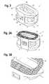
- FIG. 3Ashows a perspective view of the spinal implant of the present invention
- FIG. 3Bshows a partial perspective view highlighting a portion of the implant illustrated in FIG. 3A ;
- FIG. 4Ashows a partial top view of a surface of the implant of the present invention following a first exemplary processing step
- FIG. 4Bshows a partial top view of the surface of the implant of the present invention shown in FIG. 4A , following a second exemplary processing step;
- FIG. 4Cshows a partial top view of the surface of the implant of the present invention shown in FIG. 4B , following a third exemplary processing step.
- FIG. 4Dshows a top view of the completed surface of the implant of the present invention following the processing steps shown in FIGS. 4A , 4 B, and 4 C.
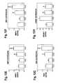
- FIGS. 5A , 5 B, and 5 Cshow confocal laser microscopy images and average-roughness (S a ) values of PEEK (A), sTiAIV (B), and rTiAIV (C) surfaces of 644 ⁇ 644 ⁇ m 2 field.
- FIGS. 6A , 6 B, 6 C, 6 D, 6 E, and 6 Fshow SEM images of PEEK (A, B), sTiAIV (C, D), and rTiAIV (E, F) surfaces at low and high magnifications.
- FIG. 7AShows the three features; Macro, Micron/Submicron and Nano size.
- FIG. 7BShows the size range and roughness of the Macro feature.
- FIG. 7CShows the size range and roughness of the Micron/Submicron features.
- FIG. 7DShows the size range and roughness of the Nano feature.
- FIGS. 7A-7Dshow relative size limitations and surface roughness features of this invention.
- FIG. 8shows an exemplary dimple pattern surface of this invention in macroscopic and microscopic detail.
- the patterns of dimples 1 , 2 , 3are overlapping, but they are sized and aligned so as not to either remove the previous dimple.
- the depthis greatest for 1 and ascends till step 3 with the sizes of the cuts increasing from 1 to 3.
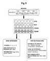
- FIG. 9is a schematic representation of human osteoblast-like MG63 cell cultures in accordance with an embodiment of the present invention.
- FIG. 1Ashows a spinal column 100 including an upper vertebra 102 and a lower vertebra 103 separated by a healthy, flexible disc 104 a .
- FIG. 1Bshows the spinal column 100 with the upper vertebra 102 and the lower vertebra 103 separated by a damaged or collapsed disc 104 b .
- the damaged disc 104 btypically requires surgical intervention to attain fusion and stabilization for complete healing and the relief of pain.
- a device according to this inventione.g., a spinal implant, is used to replace the damaged disc 104 b and provides strong initial stability, rapid healing, and bone repair.
- an interbody spinal implant 1that serves as a spacer between adjacent vertebrae.
- the implant 1may be comprised of titanium, a titanium alloy, organic polymers such as polyaryletheretherketone (“PEEK”) materials, ceramics, and other suitable materials known to people of skill in the art.
- PEEKpolyaryletheretherketone
- the implant 1comprises an implant body 5 with a top surface 10 , a bottom surface 20 , opposing lateral sides 30 , and opposing anterior 40 and posterior 50 portions.
- the implant 1has a sharp edge 8 where the anterior portion 40 meets the top surface 10 and where the anterior portion 40 meets the bottom surface 20 .
- a delivery device(not shown) can engage opening 90 in the anterior portion 40 of the implant 1 , allowing the user to manipulate the implant 1 during placement between vertebrae.
- the implant 1is substantially hollow and has a generally oval-shaped transverse cross-sectional area with smooth and/or rounded lateral sides and rounded posterior-lateral corners.
- the implant 1includes at least one aperture 60 that extends the entire height of the implant body.
- the implant 1may further include at least one aperture 70 that extends the entire transverse length of the implant body. These transverse apertures 70 may provide improved visibility of the implant 1 during surgical procedures to ensure proper implant seating and placement, and may also improve post-operative assessment of implant fusion.
- the substantially hollow areamay be filled with cancellous autograft bone, allograft bone, demineralized bone matrix (DBM), porous synthetic bone graft substitute, bone morphogenic protein (BMP), or combinations thereof, to facilitate the formation of a solid fusion column within the patient's spine.
- DBMdemineralized bone matrix
- BMPbone morphogenic protein
- the implant 1further includes a designed surface topography 80 .
- the designed surface topography 80is provided on at least a portion of the top surface 10 , the bottom surface 20 , or both the top and bottom surfaces 10 , 20 of the implant 1 for gripping adjacent bone and inhibiting migration of the implant.
- each surface 10 and 20has a designed surface topography 80 that promotes anchoring and healing of spinal tissues.
- the three-dimensional surface of the implant 1determines its ultimate ability to integrate into the surrounding living bone. Without being limited by theory, it is hypothesized that the cumulative effects of at least implant composition, implant surface energy, and implant surface topography play a major role in the biological response to, and osteointegration of, the implant 1 .
- the addition of macro, micron/submicron and nano sized features in the ranges as stated in the table belowstimulate the growth of the bone cellular structures by working in concert with well understood bone modeling and structures.
- the overall 3 dimensional shape of boneis not of a repeating structure but at a cellular level as in the Haversian Canal the structure is repeating and regular.
- the resulting stimulationworks in concert with the other structural features of the invention and balances the performance of the implant as a fusion device with sufficient resistance to expulsion and mobility to succeed in the initial stabilization of the device and the long term incorporation of rigid fusion of the vertebrae.
- Roughness Size(Ra) Size (Rz) (Ra) Size (Rz) (Ra) 50 ⁇ m-200 ⁇ m 10 ⁇ m-30 ⁇ m 500 nm-20 ⁇ m 5 ⁇ m-10 ⁇ m 200 nm-500 nm .5 ⁇ m-5 ⁇ m
- Ostointegrationas that term is used here is intended to mean the formation of a direct structural and functional interface between an artificial implant, and living boned. In a narrower sense, osteointegration occurs without the presence of soft tissue between bone and implant.
- implant fixationmay be, at least in part, dependant on the attachment and proliferation of osteoblasts, and like functioning, cells upon the implant surface. Still further, it appears that these cells attach more readily to relatively rough surfaces rather than smooth surfaces. In this manner, a surface may be bioactive due to its ability to facilitate cellular attachment and osteointegration. Without being limited by theory, it is believed that the designed surface topography and predefined depths of these features 80 may better promote the osteointegration of the implant 1 . The designed surface topography 80 may also better grip the vertebral endplate surface(s) and inhibit implant migration upon placement and seating. This is accomplished through the designed patterns of the features including the depths of the overlapping patterns.
- the present inventionprovides the implant 1 having an implant body 5 that defines a designed surface topography 80 that is both three dimensional and intentionally patterned.
- the designed surface topography 80is produced in multiple steps using tooling of a specified shape and size.
- the designed surface topography 80is adapted to create a large surface area of bone-contacting features that allow for in-growth and biological attachment to a biocompatible material.
- the designed surface topography 80 of an implant 1 of this inventionhas specific patterns. By overlapping these patterns, the designed surface topography 80 may be used as an integration surface with features of a desirable size for bone growth (specifically implant in-growth) and attachment and to aid in resisting forces that act on the implant 1 , thereby improving stability and overall success of the procedure.
- the designed surface topography 80 with a defined pattern of the implant 1facilitates the installation of the implant 1 and enhances the initial, intermediate, and long-term stability of the implant 1 .
- the designed surface topography 80is created using predictable and repeatable process steps, such as mechanical or chemical machining, photo etching or adaptations of laser or plasma welding technologies. These steps allow for variations of the surface patterns on individual implant working surface so that areas that may benefit from more or less aggressive features may be formed.
- the three dimensional patternscan also be varied is ways that can be used to fine tune various areas of the implant bodies initial fixation due to contact with the vertebral body and it's relative construction.
- the designed surface topography 80may be oriented to resist biological loading better than randomly generated surfaces.
- treads on automobile tiresare designed with specific functions in mind: grip in the forward direction, for example, and stability in the lateral direction.
- the designed selected, planned or strategically chosen surface topography 80 of the present inventioncan be predetermined with specific functions in mind.
- predeterminedis meant determined beforehand, so that the predetermined pattern is determined, i.e., chosen, selected or at least known or in mind, before processing begins and in view of the post-implant medical environment).
- the designed surface topography 80 on the top surface 10 in the anterior portion 40may have larger and sharper features to resist expulsion of the implant 1 from between the vertebrae, for example, while the designed surface topography 80 on the top surface 10 in the posterior portion 50 may have smaller and less sharp features to facilitate placement of the implant 1 .
- the implant 1does not have any unintentional sharp edges or protrusions (excepting sharp edges 8 which are intentionally provided to permit implant 1 to resist expulsion from between adjacent vertebra). These sharp edges or protrusions sometimes result in focal points for loading and the resulting loss of osseous tissues through stress-induced bone loss. This is also considered in concert with the structural properties of the vertebral body, which is commonly stiffer on the outer edges and has greater mobility towards their center surfaces.
- the implant surfacethat has synthetic and or biologically derived materials applied to it allows for “seeding” in specific locations of these materials acting in concert with the microscopic surface enhancements generated in the production process.
- the designed surface topography 80has features in a defined size range that are beneficial to the biological growth and remodeling of bone tissues subjected to loading in several directions.
- the designed surface topography 80 of the implant 1is the connection point for the load-bearing or working surface of the implant 1 and the live osseous tissue of the vertebrae.
- the designed surface topography 80allows for initial stabilization and long-term bone in-growth and fusion. Larger surface areas and a smooth and contoured surface provide more assured and effective initial, intermediate, and long-term outcomes and overall benefit to a patient.
- micro surfaces created through subtractive chemical or mechanical processesis an achievable and commercially viable way to increase the surface area for dissipating variable loads and compensating for variable bone conditions. Smaller features that allow for dissipated forces but having a regulated, designed pattern are beneficial in treating the largest possible number of patients having the largest number of variables.
- Exemplary embodiments of the implant bodycomprise many various bodies of various sizes and biocompatible materials that have surface enhancements consistent with the designed surface topography 80 of machined and acid etching refined surfaces.
- the designed surface topography 80can be formed in multiple steps using very small tooling often referred to as micro drills or milling cutters in high speed, highly precise, milling equipment. These practices are contrary to common efforts to remove large amounts of material as quickly as possible. Optimization of the surface geometry and the ability to define repeating patterns to predefined depths is beneficial to the overall product design can be achieved using these processes and others.
- the first process stepcreates a first feature 82 of the designed surface topography 80 on the top surface 10 of the implant 1 .
- the first feature 82is typically the deepest feature of the designed surface topography 80 and may be, for example, 0.021 inches deep (or more) into the surface of the implant 1 (along the Z axis as illustrated).
- a wide variety of processescan be applied to create the first feature 82 .
- the first featureis a spherical indent which might be created, for example, by the use of a ball-shaped tool (e.g., by “peening” or drilling).
- subsequent processing or finishing stepse.g., polishing, may be employed to remove incidentally-created surface artifacts which are not part of the feature.
- the designed surface topography 80 of the implant 1is produced by overlapping several features.
- the second process stepcreates a second feature 84 of the designed surface topography 80 of the implant 1 but up to the depth of the first feature.
- the second feature 84is typically the second deepest feature of the designed surface topography 80 and may be, for example, 0.014 inches deep into the surface of the implant 1 .
- a wide variety of processescan be applied to create the second feature 84 .
- the depth and X-Y placement of the second feature 84are selected so that the second feature 84 does not directly overlap and wipe out the first feature 82 (to highlight the second feature 84 and for purposes of clarity the first feature 82 is not shown in FIG.
- first feature 82exists in combination with the second feature 84 ).
- the depth variations and alignment to the expected load directionwill have the same net effect as a single feature of the same depth, but in other lower loaded directions will minimize focused loading and reduce stresses that the bone is subjected to when lower loading is applied.
- incidentally-created process artifactse.g., burrs, splays, may need to be removed using well known techniques.
- the third process stepcreates a third feature 86 of the designed surface topography 80 of the implant 1 .
- the third feature 86is typically the shallowest feature of the designed surface topography 80 and may be, for example, 0.007 inches deep into the surface of implant 1 but less than the depth of the second feature 84 .
- a wide variety of processescan be applied to create the third feature 86 .
- the depth and X-Y placement of the third feature 86are selected so that the third feature 86 does not directly overlap and wipe out the first feature 82 or the second feature 84 (to highlight the third feature 86 and for purposes of clarity the first feature 82 and the second feature 84 are not shown in FIG.
- FIGS. 4A , 4 B, and 4 Cdepict exemplary process steps with different surfaces.
- the designed surface topography 80 following the multi-step sequential application of process stepsshown as bracket 88 and indicating the completed workpiece or working surface
- final working surface of implant body 5is shown in FIG. 4D .
- the implant 1 illustrated in FIG. 4Dcombines machined and acid etched micro surfaces that behave in a similar manner with regard to the bone tissues, but add directional stability by having an organized pattern that resists loading and potential movement of the implant 1 .
- the designed surface topography 80 of the implant 1is produced by overlapping several features. This results in a large surface area of defined geometric shapes and patterns. Preferably, the process steps include repeating shapes between the machining steps to produce a large surface area having a defined pattern.
- the designed surface topography 80may also be refined using mechanical, focused energy or chemical processes to improve the implant surface.
- the designed surface topography 80may be obtained through a variety of techniques including, without limitation, chemical or acid etching, shot peening, plasma etching, laser etching, or abrasive blasting, such as sand or grit blasting.
- a roughened surface topographyis obtained via the repetitive masking and chemical or electrochemical milling processes described in U.S. Pat. No. 5,258,098; No. 5,507,815; No. 5,922,029; and No. 6,193,762, each incorporated herein by reference.
- Interbody spinal implants 1may be comprised, in accordance with preferred embodiments of the present invention, of titanium or a titanium alloy having an average surface roughness of about 100 ⁇ m on the top surface 10 and on the bottom surface 20 . Surface roughness may be measured using a laser profilometer or other standard instrumentation.
- the implant surfaceis produced using defined and adapted tooling that, when patterns of these features are overlapped in a predetermined manner, result in an improved surface capable of sustaining osseous in-growth under loading.
- Various chemicals, such as acids,may be used to refine the contours of the implant surface. The result of such refinement is a relatively smooth surface free from manufacturing debris and well adapted to biological behavior of bone tissues.
- implants 1 of the exemplary typeare typically difficult to manipulate and precisely place without instruments.
- the body of the implanttypically includes at least three, and sometimes more than three, instrument connections (such as the opening 90 ) that can be threaded, force fit, or snap fit together to rigidly connect the implant 1 and withstand placement in the vertebrae.
- instrument connectionssuch as the opening 90
- the force fit of the implant 1 into the intravertebral spacecreates initial stability of the device and incorporates the bone tissues into the surface of the implant 1 .
- Titanium implants with physical-chemical modifications such as micron or submicron scale topographic featureshave been shown to increase osteoblast differentiation and local factor production in vivo and to increase pen-implant bone formation and decrease healing time in vivo.
- Polyetheretherketone (PEEK)is used as a cage or spacer in vertebral interbody fusion to maintain spinal alignment and segmental stability while facilitating bony fusion.
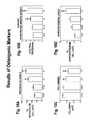
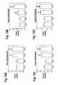
- the aim of this analysiswas to elucidate whether common intervertebral materials such as PEEK and titanium alloy (Ti6AI4V) induce osteoblast maturation and generate an osteogenic environment.
- FIGS. 5A , 5 B, and 5 CConfocal laser microscopy images and average-roughness (S a ) values of PEEK (A), sTiAIV (B), and rTiAIV (C) surfaces of 644 ⁇ 644 ⁇ m 2 field.
- FIGS. 6A , 6 B, 6 C, 6 D, 6 E, and 6 FSEM images of PEEK (A, B), sTiAIV (C, D), and rTiAIV (E, F) surfaces at low and high magnifications.
- Human MG63 osteoblast-like cellswere harvested 24 hours after confluence on TCPS.
- Osteoblasts cultured on Ti6AI4Vproduce and regulate BMP pathway molecules, increasing BMP2, BMP4, BMP7, and physiologic BMP inhibitors.
- One reason for the differential response of osteoblasts to PEEK and TiALVmay result from differences in integrin expression downstream signaling by these receptors.
- surface properties, including the composition of the bulk material,are important in directing cell response to implant materials, ultimately affecting implant success.
- the instrumentation and installation practices of this inventionare used in not only spinal surgery, but also in common orthopedic treatment of many of the bones and joints in the body.
- Common hip and knee implantsoften use a force fit or interference fit to initially stabilize the implants and promote long-term success.
- These instruments and the connection to the implantsare correspondingly durable and robust enough to withstand loading, impacts, and forces resulting from the procedures.
Landscapes
- Health & Medical Sciences (AREA)
- Engineering & Computer Science (AREA)
- Biomedical Technology (AREA)
- Orthopedic Medicine & Surgery (AREA)
- Neurology (AREA)
- Heart & Thoracic Surgery (AREA)
- Oral & Maxillofacial Surgery (AREA)
- Transplantation (AREA)
- Cardiology (AREA)
- Vascular Medicine (AREA)
- Life Sciences & Earth Sciences (AREA)
- Animal Behavior & Ethology (AREA)
- General Health & Medical Sciences (AREA)
- Public Health (AREA)
- Veterinary Medicine (AREA)
- Prostheses (AREA)
Abstract
Description
| Surface Feature size and Roughness |
| Macro | Roughness | Micron/Submicron | Roughness | Nano | Roughness |
| Size (Rz) | (Ra) | Size (Rz) | (Ra) | Size (Rz) | (Ra) |
| 50 μm-200 | 10 μm-30 μm | 500 nm-20 | 5 μm-10 μm | 200 nm-500 nm | .5 μm-5 μm |
Claims (19)
Priority Applications (6)
| Application Number | Priority Date | Filing Date | Title |
|---|---|---|---|
| US13/286,813US8992619B2 (en) | 2011-11-01 | 2011-11-01 | Microstructured implant surfaces |
| EP12846676.0AEP2773294B1 (en) | 2011-11-01 | 2012-01-23 | Microstructured implant surfaces |
| EP20167392.8AEP3718513B1 (en) | 2011-11-01 | 2012-01-23 | Microstructured implant surfaces |
| PCT/US2012/022192WO2013066376A1 (en) | 2011-11-01 | 2012-01-23 | Microstructured implant surfaces |
| EP22194230.3AEP4129240A1 (en) | 2011-11-01 | 2012-01-23 | Microstructured implant surfaces |
| US14/644,274US9314337B2 (en) | 2011-11-01 | 2015-03-11 | Microstructured implant surfaces |
Applications Claiming Priority (1)
| Application Number | Priority Date | Filing Date | Title |
|---|---|---|---|
| US13/286,813US8992619B2 (en) | 2011-11-01 | 2011-11-01 | Microstructured implant surfaces |
Related Child Applications (1)
| Application Number | Title | Priority Date | Filing Date |
|---|---|---|---|
| US14/644,274ContinuationUS9314337B2 (en) | 2011-11-01 | 2015-03-11 | Microstructured implant surfaces |
Publications (2)
| Publication Number | Publication Date |
|---|---|
| US20130110243A1 US20130110243A1 (en) | 2013-05-02 |
| US8992619B2true US8992619B2 (en) | 2015-03-31 |
Family
ID=48173188
Family Applications (2)
| Application Number | Title | Priority Date | Filing Date |
|---|---|---|---|
| US13/286,813Active2032-06-17US8992619B2 (en) | 2011-11-01 | 2011-11-01 | Microstructured implant surfaces |
| US14/644,274ActiveUS9314337B2 (en) | 2011-11-01 | 2015-03-11 | Microstructured implant surfaces |
Family Applications After (1)
| Application Number | Title | Priority Date | Filing Date |
|---|---|---|---|
| US14/644,274ActiveUS9314337B2 (en) | 2011-11-01 | 2015-03-11 | Microstructured implant surfaces |
Country Status (3)
| Country | Link |
|---|---|
| US (2) | US8992619B2 (en) |
| EP (3) | EP3718513B1 (en) |
| WO (1) | WO2013066376A1 (en) |
Cited By (16)
| Publication number | Priority date | Publication date | Assignee | Title |
|---|---|---|---|---|
| US20150366668A1 (en)* | 2014-06-23 | 2015-12-24 | Community Blood Center | Cellular-scale surface modification for increased osteogenic protein expression |
| US10182923B2 (en) | 2015-01-14 | 2019-01-22 | Stryker European Holdings I, Llc | Spinal implant with porous and solid surfaces |
| US20190076258A1 (en)* | 2017-09-14 | 2019-03-14 | Craig Black | Medical Devices, Medical Device Precursors, and Methods of Making Medical Devices |
| US10271959B2 (en) | 2009-02-11 | 2019-04-30 | Howmedica Osteonics Corp. | Intervertebral implant with integrated fixation |
| US10414022B2 (en) | 2014-04-11 | 2019-09-17 | Biomet 3I, Llc | Implant with high primary stability and accelerated secondary stability |
| US10537666B2 (en) | 2015-05-18 | 2020-01-21 | Stryker European Holdings I, Llc | Partially resorbable implants and methods |
| US10596660B2 (en) | 2015-12-15 | 2020-03-24 | Howmedica Osteonics Corp. | Porous structures produced by additive layer manufacturing |
| US10603182B2 (en) | 2015-01-14 | 2020-03-31 | Stryker European Holdings I, Llc | Spinal implant with fluid delivery capabilities |
| US10736752B1 (en) | 2017-10-24 | 2020-08-11 | Omnia Medical, LLC | Multi-material multi-component spinal implant |
| US10835388B2 (en) | 2017-09-20 | 2020-11-17 | Stryker European Operations Holdings Llc | Spinal implants |
| US10888362B2 (en) | 2017-11-03 | 2021-01-12 | Howmedica Osteonics Corp. | Flexible construct for femoral reconstruction |
| US11051953B2 (en) | 2019-07-31 | 2021-07-06 | Zavation Medical Products, Llc | Porous spinal implant |
| US11065126B2 (en) | 2018-08-09 | 2021-07-20 | Stryker European Operations Holdings Llc | Interbody implants and optimization features thereof |
| US11628517B2 (en) | 2017-06-15 | 2023-04-18 | Howmedica Osteonics Corp. | Porous structures produced by additive layer manufacturing |
| US20230277328A1 (en)* | 2019-07-31 | 2023-09-07 | Zavation Medical Products, Llc | Porous spinal implant |
| US11766339B1 (en) | 2017-10-24 | 2023-09-26 | Omnia Medical, LLC | Multi-material multi-component spinal implant |
Families Citing this family (47)
| Publication number | Priority date | Publication date | Assignee | Title |
|---|---|---|---|---|
| US20080161929A1 (en) | 2006-12-29 | 2008-07-03 | Mccormack Bruce | Cervical distraction device |
| WO2009089367A2 (en) | 2008-01-09 | 2009-07-16 | Providence Medical Technology, Inc. | Methods and apparatus for accessing and treating the facet joint |
| US11224521B2 (en) | 2008-06-06 | 2022-01-18 | Providence Medical Technology, Inc. | Cervical distraction/implant delivery device |
| US8267966B2 (en) | 2008-06-06 | 2012-09-18 | Providence Medical Technology, Inc. | Facet joint implants and delivery tools |
| US9381049B2 (en) | 2008-06-06 | 2016-07-05 | Providence Medical Technology, Inc. | Composite spinal facet implant with textured surfaces |
| US8361152B2 (en) | 2008-06-06 | 2013-01-29 | Providence Medical Technology, Inc. | Facet joint implants and delivery tools |
| US9333086B2 (en) | 2008-06-06 | 2016-05-10 | Providence Medical Technology, Inc. | Spinal facet cage implant |
| CA2725811A1 (en) | 2008-06-06 | 2009-12-10 | Providence Medical Technology, Inc. | Facet joint implants and delivery tools |
| EP2361046B1 (en) | 2008-06-06 | 2019-04-24 | Providence Medical Technology, Inc. | Cervical distraction/implant delivery device |
| USD732667S1 (en) | 2012-10-23 | 2015-06-23 | Providence Medical Technology, Inc. | Cage spinal implant |
| USD745156S1 (en) | 2012-10-23 | 2015-12-08 | Providence Medical Technology, Inc. | Spinal implant |
| GB201402804D0 (en) | 2014-02-17 | 2014-04-02 | Univ Manchester | Implants |
| AU2015267055B2 (en) | 2014-05-27 | 2020-04-02 | Christopher U. Phan | Lateral mass fixation implant |
| JP2017520357A (en) | 2014-05-28 | 2017-07-27 | プロビデンス メディカル テクノロジー インコーポレイテッド | Outer mass fixing system |
| US10687956B2 (en) | 2014-06-17 | 2020-06-23 | Titan Spine, Inc. | Corpectomy implants with roughened bioactive lateral surfaces |
| US10028841B2 (en) | 2015-01-27 | 2018-07-24 | K2M, Inc. | Interbody spacer |
| US20160213405A1 (en) | 2015-01-27 | 2016-07-28 | K2M, Inc. | Vertebral plate systems and methods of use |
| USD841165S1 (en) | 2015-10-13 | 2019-02-19 | Providence Medical Technology, Inc. | Cervical cage |
| CN108289689A (en) | 2015-10-13 | 2018-07-17 | 普罗维登斯医疗技术公司 | Joint of vertebral column implantation material conveying device and system |
| TWI726940B (en) | 2015-11-20 | 2021-05-11 | 美商泰坦脊柱股份有限公司 | Processes for additively manufacturing orthopedic implants |
| GB201521474D0 (en) | 2015-12-04 | 2016-01-20 | Univ Manchester | Textured surfaces for implants |
| EP3386444B1 (en) | 2015-12-07 | 2020-11-18 | Nexus Spine, L.L.C. | Porous interbody spacer |
| EP3222251B1 (en)* | 2016-03-21 | 2018-12-05 | 41Medical AG | Expandable spinal implant |
| US11045307B2 (en) | 2016-05-11 | 2021-06-29 | Establishment Labs S.A. | Medical implants and methods of preparation thereof |
| TW201806562A (en) | 2016-06-28 | 2018-03-01 | 普羅維登斯醫療科技公司 | Spinal implant and methods of using the same |
| USD887552S1 (en) | 2016-07-01 | 2020-06-16 | Providence Medical Technology, Inc. | Cervical cage |
| CA3032664A1 (en) | 2016-08-03 | 2018-02-08 | Titan Spine, Inc. | Implant surfaces that enhance osteoinduction |
| US10675159B2 (en)* | 2017-02-08 | 2020-06-09 | Osseus Fusion Systems, Llc | Composite interbody system |
| US11871968B2 (en) | 2017-05-19 | 2024-01-16 | Providence Medical Technology, Inc. | Spinal fixation access and delivery system |
| EP3415108B1 (en) | 2017-05-25 | 2024-09-04 | Stryker European Operations Holdings LLC | Fusion cage with integrated fixation and insertion features |
| WO2019006013A1 (en)* | 2017-06-28 | 2019-01-03 | The Regents Of The University Of California | Medical implants with improved roughness |
| US11006981B2 (en) | 2017-07-07 | 2021-05-18 | K2M, Inc. | Surgical implant and methods of additive manufacturing |
| WO2019051260A1 (en) | 2017-09-08 | 2019-03-14 | Pioneer Surgical Technology, Inc. | Intervertebral implants, instruments, and methods |
| US11648128B2 (en) | 2018-01-04 | 2023-05-16 | Providence Medical Technology, Inc. | Facet screw and delivery device |
| CN111770739B (en) | 2018-02-18 | 2024-10-25 | G&G生物技术有限公司 | Implant with enhanced shell adhesion |
| WO2020061464A1 (en) | 2018-09-21 | 2020-03-26 | Providence Medical Technology, Inc. | Vertebral joint access and decortication devices and methods of using |
| USD933230S1 (en) | 2019-04-15 | 2021-10-12 | Providence Medical Technology, Inc. | Cervical cage |
| US11583408B2 (en) | 2019-05-18 | 2023-02-21 | Anjali Investments Llc | Minimally invasive posterior cervical facet arthrodesis shim implant and tools therefor |
| USD911525S1 (en) | 2019-06-21 | 2021-02-23 | Providence Medical Technology, Inc. | Spinal cage |
| US11534307B2 (en) | 2019-09-16 | 2022-12-27 | K2M, Inc. | 3D printed cervical standalone implant |
| US11278420B2 (en) | 2019-10-25 | 2022-03-22 | Zavation, Llc | Recessed pocket spinal implant |
| USD945621S1 (en) | 2020-02-27 | 2022-03-08 | Providence Medical Technology, Inc. | Spinal cage |
| US11426904B2 (en) | 2020-09-11 | 2022-08-30 | Happe Spine Llc | Implantable medical device with varied composition and porosity, and method for forming same |
| AU2021402907B2 (en)* | 2020-12-18 | 2024-06-27 | Spine Wave, Inc. | Expandable tlif device and related insertion and grafting instrumentation |
| NL2027599B1 (en) | 2021-02-19 | 2022-09-19 | Instructure Labs B V | Biocompatible polymeric implant material having a textured surface |
| TWI820827B (en)* | 2022-07-27 | 2023-11-01 | 明志科技大學 | Surface treated intervertebral cage |
| US12029653B1 (en) | 2023-06-14 | 2024-07-09 | Spine Wave, Inc. | Medical implant having a textured tissue contact surface |
Citations (248)
| Publication number | Priority date | Publication date | Assignee | Title |
|---|---|---|---|---|
| US4314876A (en) | 1980-03-17 | 1982-02-09 | The Diversey Corporation | Titanium etching solution |
| US4834757A (en) | 1987-01-22 | 1989-05-30 | Brantigan John W | Prosthetic implant |
| US4904261A (en) | 1987-08-06 | 1990-02-27 | A. W. Showell (Surgicraft) Limited | Spinal implants |
| US5015247A (en) | 1988-06-13 | 1991-05-14 | Michelson Gary K | Threaded spinal implant |
| US5071437A (en) | 1989-02-15 | 1991-12-10 | Acromed Corporation | Artificial disc |
| US5258098A (en) | 1991-06-17 | 1993-11-02 | Cycam, Inc. | Method of production of a surface adapted to promote adhesion |
| US5306308A (en) | 1989-10-23 | 1994-04-26 | Ulrich Gross | Intervertebral implant |
| US5306309A (en) | 1992-05-04 | 1994-04-26 | Calcitek, Inc. | Spinal disk implant and implantation kit |
| EP0599419A2 (en) | 1992-11-26 | 1994-06-01 | ESKA Implants GmbH & Co. | Disk-shaped implant for reinforcing adjacent vertebrae |
| US5425772A (en) | 1993-09-20 | 1995-06-20 | Brantigan; John W. | Prosthetic implant for intervertebral spinal fusion |
| US5443514A (en) | 1993-10-01 | 1995-08-22 | Acromed Corporation | Method for using spinal implants |
| US5456723A (en) | 1989-03-23 | 1995-10-10 | Institut Straumann Ag | Metallic implant anchorable to bone tissue for replacing a broken or diseased bone |
| JPH0810276Y2 (en) | 1990-02-23 | 1996-03-29 | ダイワ精工株式会社 | Fishing rod |
| US5571188A (en) | 1992-12-04 | 1996-11-05 | Astra Aktiebolag | Process for treating a metallic surgical implant |
| US5603338A (en) | 1994-11-30 | 1997-02-18 | Innovative Implants, Inc. | Implant surface preparation utilizing acid treatment |
| US5609635A (en) | 1988-06-28 | 1997-03-11 | Michelson; Gary K. | Lordotic interbody spinal fusion implants |
| WO1997006753A3 (en) | 1995-08-11 | 1997-04-24 | Bernhard Zientek | Intervertebral implant, process for widening and instruments for implanting an intervertebral implant |
| US5702449A (en) | 1995-06-07 | 1997-12-30 | Danek Medical, Inc. | Reinforced porous spinal implants |
| WO1998001091A1 (en) | 1995-10-16 | 1998-01-15 | Sdgi Holdings, Inc. | Implant insertion device |
| US5755798A (en) | 1995-10-26 | 1998-05-26 | Artos Medizinische Produkte Gmbh | Intervertebral implant |
| US5766252A (en) | 1995-01-24 | 1998-06-16 | Osteonics Corp. | Interbody spinal prosthetic implant and method |
| US5776199A (en) | 1988-06-28 | 1998-07-07 | Sofamor Danek Properties | Artificial spinal fusion implants |
| US5860973A (en) | 1995-02-27 | 1999-01-19 | Michelson; Gary Karlin | Translateral spinal implant |
| US5863201A (en) | 1994-11-30 | 1999-01-26 | Implant Innovations, Inc. | Infection-blocking dental implant |
| US5865845A (en) | 1996-03-05 | 1999-02-02 | Thalgott; John S. | Prosthetic intervertebral disc |
| US5885079A (en) | 1998-06-22 | 1999-03-23 | Core-Vent Corporation | Selective surface, endosseous dental implants |
| US5888224A (en) | 1993-09-21 | 1999-03-30 | Synthesis (U.S.A.) | Implant for intervertebral space |
| US5968098A (en) | 1996-10-22 | 1999-10-19 | Surgical Dynamics, Inc. | Apparatus for fusing adjacent bone structures |
| US5984922A (en) | 1993-07-09 | 1999-11-16 | Mckay; Douglas William | Spinal fixation device and method |
| US6033582A (en) | 1996-01-22 | 2000-03-07 | Etex Corporation | Surface modification of medical implants |
| US6039762A (en) | 1995-06-07 | 2000-03-21 | Sdgi Holdings, Inc. | Reinforced bone graft substitutes |
| US6059829A (en) | 1995-03-08 | 2000-05-09 | Synthese | Intervertebral implant |
| US6080158A (en) | 1999-08-23 | 2000-06-27 | Lin; Chih-I | Intervertebral fusion device |
| US6086613A (en) | 1997-12-23 | 2000-07-11 | Depuy Acromed, Inc. | Spacer assembly for use in spinal surgeries |
| US6096107A (en) | 2000-01-03 | 2000-08-01 | Norton Company | Superabrasive products |
| US6123705A (en) | 1988-06-13 | 2000-09-26 | Sdgi Holdings, Inc. | Interbody spinal fusion implants |
| US6143032A (en) | 1997-11-12 | 2000-11-07 | Schafer Micomed Gmbh | Intervertebral implant |
| US6176882B1 (en) | 1998-02-20 | 2001-01-23 | Biedermann Motech Gmbh | Intervertebral implant |
| US6183255B1 (en) | 2000-03-27 | 2001-02-06 | Yoshiki Oshida | Titanium material implants |
| US6193757B1 (en) | 1998-10-29 | 2001-02-27 | Sdgi Holdings, Inc. | Expandable intervertebral spacers |
| US6241771B1 (en) | 1997-08-13 | 2001-06-05 | Cambridge Scientific, Inc. | Resorbable interbody spinal fusion devices |
| US6241770B1 (en) | 1999-03-05 | 2001-06-05 | Gary K. Michelson | Interbody spinal fusion implant having an anatomically conformed trailing end |
| US6245108B1 (en) | 1999-02-25 | 2001-06-12 | Spineco | Spinal fusion implant |
| JP2001170092A (en) | 1999-12-21 | 2001-06-26 | Nippon Electric Glass Co Ltd | Vertebral arch spacer for enlarging operation of vertebral canal |
| US20010014826A1 (en) | 1995-02-14 | 2001-08-16 | Lutz Biedermann | Space holder, in particular for a vertebra or an intervertebral disk |
| WO2001070144A1 (en) | 2000-03-22 | 2001-09-27 | Scolio Gmbh | Cage-type intervertebral implant |
| US6296664B1 (en) | 1998-06-17 | 2001-10-02 | Surgical Dynamics, Inc. | Artificial intervertebral disc |
| US20010039454A1 (en) | 1993-11-02 | 2001-11-08 | John Ricci | Orthopedic implants having ordered microgeometric surface patterns |
| US20010047208A1 (en) | 1999-12-08 | 2001-11-29 | Michelson Gary K. | Spinal implant surface configuration |
| WO2001095838A1 (en) | 2000-06-12 | 2001-12-20 | Ortho Development Corporation | Intervertebral spacer |
| US6342074B1 (en) | 1999-04-30 | 2002-01-29 | Nathan S. Simpson | Anterior lumbar interbody fusion implant and method for fusing adjacent vertebrae |
| WO2001028469B1 (en) | 1999-10-21 | 2002-01-31 | Sdgi Holdings Inc | Devices and techniques for a posterior lateral disc space approach |
| US6344057B1 (en) | 1994-11-22 | 2002-02-05 | Sdgi Holdings, Inc. | Adjustable vertebral body replacement |
| US6350283B1 (en) | 2000-04-19 | 2002-02-26 | Gary K. Michelson | Bone hemi-lumbar interbody spinal implant having an asymmetrical leading end and method of installation thereof |
| US6375681B1 (en) | 1998-06-23 | 2002-04-23 | Ebi, L.P. | Vertebral body replacement |
| US20020049497A1 (en) | 2000-10-11 | 2002-04-25 | Mason Michael D. | Graftless spinal fusion device |
| US6387130B1 (en) | 1999-04-16 | 2002-05-14 | Nuvasive, Inc. | Segmented linked intervertebral implant systems |
| US20020087212A1 (en) | 2000-12-29 | 2002-07-04 | James Stephen B. | Spinal implant |
| US6423095B1 (en) | 1995-10-16 | 2002-07-23 | Sdgi Holdings, Inc. | Intervertebral spacers |
| US20020099443A1 (en) | 1999-02-04 | 2002-07-25 | Synthes (Usa) | End member for a bone fusion implant |
| US6425920B1 (en) | 1999-10-13 | 2002-07-30 | James S. Hamada | Spinal fusion implant |
| US6432140B1 (en) | 1999-12-10 | 2002-08-13 | Chih-I Lin | Intervertebral retrieval device |
| US6436102B1 (en) | 2001-07-16 | 2002-08-20 | Third Millennium Engineering, Llc | Method of distracting vertebral bones |
| US20020128716A1 (en) | 1999-07-26 | 2002-09-12 | Howard Cohen | Spinal surgical prosthesis |
| US20020138142A1 (en) | 2001-03-23 | 2002-09-26 | Michael Castro | Modular implant for fusing adjacent bone structure |
| US6458159B1 (en) | 2000-08-15 | 2002-10-01 | John S. Thalgott | Disc prosthesis |
| US20020156529A1 (en) | 1998-03-11 | 2002-10-24 | Panjian Li | Surface-mineralized spinal implants |
| US20020161443A1 (en) | 2001-04-02 | 2002-10-31 | Michelson Gary K. | Artificial contoured spinal fusion implants made of a material other than bone |
| US6482233B1 (en) | 1998-01-29 | 2002-11-19 | Synthes(U.S.A.) | Prosthetic interbody spacer |
| US20020173854A1 (en) | 2001-01-25 | 2002-11-21 | Tecomet, Inc. | Method for making a mesh-and-plate surgical implant |
| US6485517B1 (en) | 1999-05-05 | 2002-11-26 | Gary K. Michelson | Nested interbody spinal fusion implants |
| US6491723B1 (en) | 1996-02-27 | 2002-12-10 | Implant Innovations, Inc. | Implant surface preparation method |
| US20020188294A1 (en) | 2001-04-06 | 2002-12-12 | Couture Gary M. | Vessel sealer and divider |
| US20030014116A1 (en) | 2001-07-16 | 2003-01-16 | Ralph James D. | Intervertebral spacer having a flexible wire mesh vertebral body contact element |
| US20030083668A1 (en) | 2001-10-30 | 2003-05-01 | Christopher Rogers | Slaphammer tool |
| US6558424B2 (en) | 2001-06-28 | 2003-05-06 | Depuy Acromed | Modular anatomic fusion device |
| US6569201B2 (en) | 2001-09-28 | 2003-05-27 | Depuy Acromed, Inc. | Hybrid composite interbody fusion device |
| US20030105527A1 (en) | 2001-12-03 | 2003-06-05 | Surgical Dynamics, Inc. | Apparatus for fusing adjacent bone structures |
| US20030109928A1 (en) | 2000-07-12 | 2003-06-12 | Denis Pasquet | Intersomatic implant |
| US20030125739A1 (en) | 2001-12-12 | 2003-07-03 | Bagga Charanpreet S. | Bioactive spinal implants and method of manufacture thereof |
| US6592624B1 (en) | 1999-11-24 | 2003-07-15 | Depuy Acromed, Inc. | Prosthetic implant element |
| US6599322B1 (en) | 2001-01-25 | 2003-07-29 | Tecomet, Inc. | Method for producing undercut micro recesses in a surface, a surgical implant made thereby, and method for fixing an implant to bone |
| US20030153975A1 (en) | 2002-02-12 | 2003-08-14 | Byrd John Abbott | Vertebral Interbody cage with translatable locking screw |
| US6610089B1 (en) | 1997-08-26 | 2003-08-26 | Sdgi Holdings, Inc. | Spinal implant and cutting tool preparation accessory for mounting the implant |
| US20030176925A1 (en) | 2002-03-15 | 2003-09-18 | Francois Paponneau | Vertebral body spacer having variable wedged endplates |
| US20030181980A1 (en) | 2002-03-21 | 2003-09-25 | Berry Bret M. | Vertebral body and disc space replacement devices |
| US20030181981A1 (en) | 2000-05-11 | 2003-09-25 | Jean-Philippe Lemaire | Anterior lumbar interbody implant |
| US20030187506A1 (en) | 2002-03-27 | 2003-10-02 | Raymond Ross | Modular disc prosthesis |
| US20030191531A1 (en) | 2002-03-21 | 2003-10-09 | Berry Bret M. | Vertebral body and disc space replacement devices |
| US6635086B2 (en) | 2000-05-30 | 2003-10-21 | Blacksheep Technologies Incorporated | Implant for placement between cervical vertebrae |
| US6652765B1 (en) | 1994-11-30 | 2003-11-25 | Implant Innovations, Inc. | Implant surface preparation |
| WO2004008983A1 (en) | 2002-07-19 | 2004-01-29 | Astra Tech Ab | An implant and a method for treating an implant surface |
| US6702855B1 (en) | 1999-01-29 | 2004-03-09 | Institut Straumann Ag | Osteophilic implants |
| US6719794B2 (en) | 2001-05-03 | 2004-04-13 | Synthes (U.S.A.) | Intervertebral implant for transforaminal posterior lumbar interbody fusion procedure |
| US20040073314A1 (en) | 2002-03-21 | 2004-04-15 | White John L. | Vertebral body and disc space replacement devices |
| US6730127B2 (en) | 2000-07-10 | 2004-05-04 | Gary K. Michelson | Flanged interbody spinal fusion implants |
| US6740118B2 (en) | 2002-01-09 | 2004-05-25 | Sdgi Holdings, Inc. | Intervertebral prosthetic joint |
| US6743231B1 (en) | 2000-10-02 | 2004-06-01 | Sulzer Spine-Tech Inc. | Temporary spinal fixation apparatuses and methods |
| US20040117019A1 (en) | 2000-08-30 | 2004-06-17 | Trieu Hai H. | Method and apparatus for delivering an intervertebral disc implant |
| US20040117020A1 (en) | 1999-10-21 | 2004-06-17 | George Frey | Devices and techniques for a posterior lateral disc space approach |
| US20040122518A1 (en) | 2002-12-19 | 2004-06-24 | Rhoda William S. | Intervertebral implant |
| US20040127993A1 (en) | 2002-10-16 | 2004-07-01 | Erich Kast | Spreader implant for placement between vertebrae |
| US6758849B1 (en) | 1995-02-17 | 2004-07-06 | Sdgi Holdings, Inc. | Interbody spinal fusion implants |
| US20040153160A1 (en) | 2002-10-30 | 2004-08-05 | Carrasco Mauricio Rodolfo | Implant for vertebral replacement and restoration of the normal spinal curvature |
| US20040153154A1 (en)* | 2003-01-23 | 2004-08-05 | Wolfgang Dinkelacker | Bone implant and method for manufacturing same |
| US20040162616A1 (en) | 2002-10-21 | 2004-08-19 | Simonton T. Andrew | Systems and techniques for restoring and maintaining intervertebral anatomy |
| US20040167632A1 (en) | 2003-02-24 | 2004-08-26 | Depuy Products, Inc. | Metallic implants having roughened surfaces and methods for producing the same |
| WO2004041131A3 (en) | 2002-10-31 | 2004-09-02 | Spinal Concepts Inc | Movable disc implant |
| US20040210309A1 (en) | 2001-10-11 | 2004-10-21 | Denzer Alain J | Osteophilic implants |
| US20040265780A1 (en) | 2003-05-16 | 2004-12-30 | Robb T. Tait | Surface treatment process for implants made of titanium alloy |
| US20040267367A1 (en) | 2003-06-30 | 2004-12-30 | Depuy Acromed, Inc | Intervertebral implant with conformable endplate |
| US20050021150A1 (en) | 1999-12-08 | 2005-01-27 | Michelson Gary K. | Orthopedic implant surface configuration with a projection having a back cut |
| US20050027360A1 (en) | 2003-08-01 | 2005-02-03 | Webb Scott A. | Spinal implant |
| US20050060034A1 (en) | 2003-09-15 | 2005-03-17 | Sdgi Holdings, Inc. | Revisable prosthetic device |
| US20050075734A1 (en) | 2003-10-07 | 2005-04-07 | Michael Fulton | Spinal implant |
| US20050085913A1 (en) | 2003-03-31 | 2005-04-21 | Robert Fraser | Spinal fixation plate |
| US20050119758A1 (en) | 2003-07-30 | 2005-06-02 | Bio-Lok International Inc. | Surgical implant for promotion of osseo-integration |
| US6902581B2 (en) | 2000-10-24 | 2005-06-07 | Kowmedica Osteonics Corp. | Apparatus for fusing adjacent bone structure |
| US20050131416A1 (en) | 2002-11-12 | 2005-06-16 | Jansen Keith E. | SERRATOME vertebral cortical endplate cutter |
| US20050147942A1 (en) | 2001-12-21 | 2005-07-07 | Jan Hall | Method for producing a surface structure on an implant, and such an implant |
| US20050159814A1 (en) | 2004-01-15 | 2005-07-21 | Sdgi Holdings, Inc. | Universal interference cleat |
| US20050165483A1 (en)* | 2004-01-27 | 2005-07-28 | Ray Eddie F.Iii | Bone grafts |
| US20050161120A1 (en) | 2003-06-13 | 2005-07-28 | Yukiharu Hasegawa | Orthopedic and dental endosseous implants and their preparation method |
| US6923810B1 (en) | 1988-06-13 | 2005-08-02 | Gary Karlin Michelson | Frusto-conical interbody spinal fusion implants |
| US20050203630A1 (en)* | 2000-01-30 | 2005-09-15 | Pope Bill J. | Prosthetic knee joint having at least one diamond articulation surface |
| US20050251257A1 (en) | 2004-05-04 | 2005-11-10 | Mitchell Margaret E | Spinal implants with body and insert |
| US6964687B1 (en) | 1999-07-09 | 2005-11-15 | Scient'x | Anatomical interbody implant and gripper for same |
| US6974480B2 (en) | 2001-05-03 | 2005-12-13 | Synthes (Usa) | Intervertebral implant for transforaminal posterior lumbar interbody fusion procedure |
| US6981975B2 (en) | 2002-02-02 | 2006-01-03 | Sdgi Holdings, Inc. | Method for inserting a spinal fusion implant having deployable bone engaging projections |
| US20060041313A1 (en) | 2004-08-19 | 2006-02-23 | Sdgi Holdings, Inc. | Intervertebral disc system |
| US7018418B2 (en) | 2001-01-25 | 2006-03-28 | Tecomet, Inc. | Textured surface having undercut micro recesses in a surface |
| US7018412B2 (en) | 2001-08-20 | 2006-03-28 | Ebi, L.P. | Allograft spinal implant |
| US20060093646A1 (en) | 2004-10-28 | 2006-05-04 | Cima Michael J | Orthopedic and dental implant devices providing controlled drug delivery |
| US20060100705A1 (en) | 2004-11-10 | 2006-05-11 | Rolando Puno | Intervertebral spacer |
| US7044972B2 (en) | 2001-01-30 | 2006-05-16 | Synthes Ag Chur | Bone implant, in particular, an inter-vertebral implant |
| US7048870B1 (en) | 1993-12-20 | 2006-05-23 | Astrazeneca Ab | Metallic implant and process for treating a metallic implant |
| US20060149372A1 (en) | 2004-12-17 | 2006-07-06 | Paxson Robert D | Artificial spinal disc |
| US20060149376A1 (en) | 2003-06-03 | 2006-07-06 | Shimp Lawrence A | Bioimplant with nonuniformly configured protrusions on the load bearing surfaces thereof |
| US7087085B2 (en) | 2000-07-26 | 2006-08-08 | Straumann Holding Ag | Surface-modified implants |
| WO2006081843A1 (en) | 2005-02-01 | 2006-08-10 | Advanced Medical Technologies Ag | Expandable implant placeable between two vertebral bodies |
| US20060190079A1 (en) | 2005-01-21 | 2006-08-24 | Naim Istephanous | Articulating spinal disc implants with amorphous metal elements |
| US20060219661A1 (en) | 2005-02-24 | 2006-10-05 | Towse Ross W | Surface treatment methods for implants made of titanium or titanium alloy |
| US20060235534A1 (en) | 2005-04-15 | 2006-10-19 | Gertzman Arthur A | Vertebral disc repair |
| US7128760B2 (en) | 2001-03-27 | 2006-10-31 | Warsaw Orthopedic, Inc. | Radially expanding interbody spinal fusion implants, instrumentation, and methods of insertion |
| US7137997B2 (en) | 2003-12-29 | 2006-11-21 | Globus Medical, Inc. | Spinal fusion implant |
| US20060265065A1 (en) | 2005-05-06 | 2006-11-23 | Bagga Charanpreet S | Anterior interbody spinal implant |
| US7141068B2 (en) | 2003-07-01 | 2006-11-28 | Thomas Ross | Spinal spacer assembly |
| US7144428B2 (en) | 2000-09-19 | 2006-12-05 | Eduardo Aldecoa Anitua | Method for surface treatment of implants or prosthesis made of titanium or other materials |
| US20060293748A1 (en) | 2005-06-24 | 2006-12-28 | Spineworks, Llc | Prosthetic implant, and a method and tool for the insertion of same |
| US7169183B2 (en) | 2000-03-14 | 2007-01-30 | Warsaw Orthopedic, Inc. | Vertebral implant for promoting arthrodesis of the spine |
| USD539934S1 (en) | 2005-11-04 | 2007-04-03 | Spinal Elements, Inc. | Interbody fusion device |
| US7201775B2 (en) | 2002-09-24 | 2007-04-10 | Bogomir Gorensek | Stabilizing device for intervertebral disc, and methods thereof |
| WO2006116306A3 (en) | 2005-04-26 | 2007-04-12 | Hfsc Co | Spinal implant |
| US20070093898A1 (en) | 2005-09-26 | 2007-04-26 | Schwab Frank J | Transforaminal hybrid implant |
| USD541940S1 (en) | 2005-11-04 | 2007-05-01 | Spinal Elements, Inc. | Interbody fusion device |
| US7220280B2 (en) | 2002-10-16 | 2007-05-22 | Advanced Medical Technologies Ag | Spreader implant for placement between vertebrae |
| US20070118223A1 (en) | 2005-11-23 | 2007-05-24 | Warsaw Orthopedic Inc. | Posterior Articular Disc and Method for Implantation |
| US7223289B2 (en) | 2002-04-16 | 2007-05-29 | Warsaw Orthopedic, Inc. | Annulus repair systems and techniques |
| US7226480B2 (en) | 2000-08-15 | 2007-06-05 | Depuy Spine, Inc. | Disc prosthesis |
| US7238186B2 (en) | 1995-03-27 | 2007-07-03 | Warsaw Orthopedic, Inc. | Interbody fusion device and method for restoration of normal spinal anatomy |
| US7250060B2 (en) | 2004-01-27 | 2007-07-31 | Sdgi Holdings, Inc. | Hybrid intervertebral disc system |
| US7255698B2 (en) | 1994-03-28 | 2007-08-14 | Warsaw Orthopedic, Inc. | Apparatus and method for anterior spinal stabilization |
| WO2007089905A3 (en) | 2006-02-01 | 2007-10-04 | Synthes Usa | Interspinous process spacer |
| US20070233247A1 (en) | 2005-09-26 | 2007-10-04 | Schwab Frank J | Hybrid intervertebral spinal fusion implant |
| US20070233248A1 (en) | 2005-09-26 | 2007-10-04 | Schwab Frank J | Anterior hybrid implant |
| US7288093B2 (en) | 1988-06-13 | 2007-10-30 | Warsaw Orthopedic, Inc. | Spinal fusion implant having a curved end |
| US20070260320A1 (en) | 2005-03-28 | 2007-11-08 | Peterman Marc M | Spinal system and method including lateral approach |
| US20070270956A1 (en) | 2006-04-13 | 2007-11-22 | Sdgi Holdings, Inc. | Vertebral fusion implants and methods of use |
| US20070269475A1 (en) | 2006-03-31 | 2007-11-22 | Gil Carlos E | Osteochondral plug graft trimming device and method |
| US20070270951A1 (en) | 2006-02-15 | 2007-11-22 | Reginald James Davis | Transforaminal intersomatic cage for an intervertebral fusion graft and an instrument for implanting the cage |
| US20070282441A1 (en) | 2006-05-19 | 2007-12-06 | Katie Stream | Spinal Stabilization Device and Methods |
| US20070293949A1 (en) | 2004-10-08 | 2007-12-20 | Salerni Anthony A | Interior connecting interbody cage insertional tools, methods and devices |
| US20080071380A1 (en) | 2006-09-19 | 2008-03-20 | Thomas Sweeney | Systems and Methods for Percutaneous Placement of Interspinous Process Spacers |
| US7347873B2 (en) | 1998-01-30 | 2008-03-25 | Synthes (U.S.A.) | Intervertebral allograft spacer |
| US20080077171A1 (en) | 2006-09-25 | 2008-03-27 | Spinal Elements, Inc. | Retractor |
| US20080097610A1 (en) | 2006-09-02 | 2008-04-24 | Guyer Richard D | Implantable intervertebral fusion device |
| US7368065B2 (en) | 2005-06-23 | 2008-05-06 | Depuy Products, Inc. | Implants with textured surface and methods for producing the same |
| US20080154378A1 (en)* | 2006-12-22 | 2008-06-26 | Warsaw Orthopedic, Inc. | Bone implant having engineered surfaces |
| US20080195209A1 (en) | 2001-11-09 | 2008-08-14 | Javier Garcia | Spinal implant |
| WO2008103843A1 (en) | 2007-02-22 | 2008-08-28 | Spinal Elements, Inc. | Vertebral facet joint drill and method of use |
| US20080221689A1 (en) | 2007-03-10 | 2008-09-11 | Christopher Chaput | Artificial disc with unique articulating geometry and associated methods |
| US20080249622A1 (en)* | 2007-04-05 | 2008-10-09 | Gray Wayne P | Interbody implant |
| US20080262623A1 (en)* | 2005-05-06 | 2008-10-23 | Titan Spine, Llc | Composite interbody spinal implant having openings of predetermined size and shape |
| US20080269806A1 (en) | 2007-04-24 | 2008-10-30 | Jeffrey Zhang | Prostheses for locking an artificial disc in an intervertebral disc space |
| US20080269764A1 (en) | 2007-04-25 | 2008-10-30 | Spinal Elements, Inc. | Spinal implant distractor/inserter |
| US20080288076A1 (en) | 2006-09-27 | 2008-11-20 | Teck Soo | Spinal interbody spacer |
| US20090005784A1 (en) | 2007-04-25 | 2009-01-01 | Spinal Elements, Inc. | Spinal implant distractor/inserter |
| US20090005871A1 (en) | 2007-04-10 | 2009-01-01 | David White | Suture-based orthopedic joint devices |
| WO2009006225A2 (en) | 2007-06-28 | 2009-01-08 | Spinal Elements, Inc. | Spinal stabilization device |
| US20090014243A1 (en) | 2007-07-13 | 2009-01-15 | Petrolink Usa, Llc | Breather-sampling-filler assembly for liquid reservoirs/systems |
| US20090024132A1 (en) | 2007-07-19 | 2009-01-22 | Spinal Elements, Inc. | Attachable instrument guide with detachable handle |
| WO2009029458A1 (en) | 2007-08-24 | 2009-03-05 | Spinal Elements, Inc. | Loop rod spinal stabilization device |
| US20090088853A1 (en) | 2007-09-27 | 2009-04-02 | Nexgen Spine, Inc. | Orthopedic device assembly with elements coupled by a retaining structure |
| US7517363B2 (en) | 2002-06-27 | 2009-04-14 | Depuy Acromed, Inc. | Intervertebral disc having translation |
| US20090132048A1 (en) | 2006-04-13 | 2009-05-21 | Camlog Biotechnologies Ag | Biodegrading Coatings of Salt for Protecting Implants Against Organic Contaminants |
| US20090182432A1 (en) | 1999-06-04 | 2009-07-16 | Warsaw Orthopedic, Inc. | Artificial disc implant |
| US20090187247A1 (en) | 2008-01-23 | 2009-07-23 | Metcalf Jr Newton H | Spinal implant having a resorbable anchor device for temporarily securing an interbody device to adjacent upper and lower vertebrae |
| US7569074B2 (en) | 2003-12-11 | 2009-08-04 | Warsaw Orthopedic, Inc. | Expandable intervertebral implant |
| US20090204152A1 (en) | 2004-02-06 | 2009-08-13 | Spinal Elements, Inc. | Vertebral facet joint prosthesis and method of fixation |
| USD599019S1 (en) | 2008-03-07 | 2009-08-25 | Nuvasive, Inc. | Spinal fusion implant |
| US20090234362A1 (en) | 2008-03-12 | 2009-09-17 | Spinal Elements, Inc. | Offset opposing arm spinal implant distractor/inserter |
| WO2009129262A1 (en) | 2008-04-18 | 2009-10-22 | Spinal Elements, Inc | Implant and method for facet immobilization |
| US7608107B2 (en) | 2000-07-07 | 2009-10-27 | Warsaw Orthopedic, Inc. | Expandable implant with interlocking walls and method for use thereof |
| US20090276049A1 (en) | 2005-01-28 | 2009-11-05 | Peter Weiland | Implant for Transforaminal Intracorporeal Fusion |
| WO2009140544A1 (en) | 2008-05-15 | 2009-11-19 | Spinal Elements, Inc. | Method for accessing a spinal facet joint |
| US20100076559A1 (en) | 2007-05-04 | 2010-03-25 | Titan Spine, Llc | Composite telescoping anterior interbody spinal implant |
| EP1449544B1 (en) | 2003-02-24 | 2010-04-14 | DePuy Products, Inc. | Metallic implants having roughened surfaces and methods for producing the same |
| US20100094426A1 (en) | 2008-10-14 | 2010-04-15 | Grohowski Jr Joseph A | Hybrid intervertebral spinal implant |
| US20100121385A1 (en) | 2008-11-10 | 2010-05-13 | Spinal Elements, Inc. | Rod reducer instrument for spinal surgery |
| US7744612B2 (en) | 2004-02-10 | 2010-06-29 | Spinal Elements, Inc. | System and method for protecting neurovascular structures |
| US20100173264A1 (en) | 2007-07-09 | 2010-07-08 | Astra Tech Ab | Nanosurface |
| US20100204798A1 (en) | 2005-10-21 | 2010-08-12 | Stryker Spine | System and method for fusion cage implantation |
| US20100218854A1 (en) | 2007-09-10 | 2010-09-02 | Garcia Saban Francisco J | Method for obtaining a surface of titanium-based metal implant to be inserted into bone tissue |
| US20100249937A1 (en) | 2009-03-27 | 2010-09-30 | Spinal Elements, Inc. | Flanged interbody fusion device |
| US20100274286A1 (en) | 2009-04-23 | 2010-10-28 | Spinal Elements, Inc. | Transverse connectors |
| US20100274358A1 (en) | 2009-02-25 | 2010-10-28 | Spinewelding Ag | Spine stabilization device, and method and kit for its implantation |
| US20100303722A1 (en)* | 2006-06-23 | 2010-12-02 | Sungho Jin | Articles comprising large-surface-area bio-compatible materials and methods for making and using them |
| US20110009965A1 (en) | 2009-04-03 | 2011-01-13 | Ankem Sreeramamurthy | Biomedical implantable material and methods of producing the same |
| US20110040301A1 (en) | 2007-02-22 | 2011-02-17 | Spinal Elements, Inc. | Vertebral facet joint drill and method of use |
| US7901462B2 (en) | 2005-06-23 | 2011-03-08 | Depuy Products, Inc. | Implants with textured surface and methods for producing the same |
| US20110190902A1 (en)* | 2010-01-29 | 2011-08-04 | Depuy Products, Inc. | Methods and devices for implants with improved cement adhesion |
| WO2011094748A1 (en) | 2010-02-01 | 2011-08-04 | Sb Technologies, Llc | Composite interbody device and method of manufacture |
| US20110224796A1 (en) | 2008-11-07 | 2011-09-15 | Advanced Medical Technologies Ag | Implant for fusing spinal column segments |
| US20110230970A1 (en) | 2010-03-16 | 2011-09-22 | Pinnacle Spine Group, Llc | Intervertebral implants and graft delivery systems and methods |
| US20110233169A1 (en) | 2010-03-29 | 2011-09-29 | Biomet 3I, Llc | Titanium nano-scale etching on an implant surface |
| EP2386274A1 (en) | 2010-05-14 | 2011-11-16 | Titan Spine, LLC | Interbody spinal implant having internally textured surfaces |
| US20120009341A1 (en) | 2009-02-12 | 2012-01-12 | Snu R&Db Foundation | Method for modifying the surface of a bioinert material |
| US8100955B2 (en) | 2005-03-17 | 2012-01-24 | Spinal Elements, Inc. | Orthopedic expansion fastener |
| US8157864B2 (en) | 2006-06-14 | 2012-04-17 | Eden Spine Europe Sa | Vertebral replacement device |
| US20120136443A1 (en) | 2009-03-04 | 2012-05-31 | Advanced Medical Technologies Ag | Implant system having at least three support elements |
| US20120158144A1 (en) | 2005-05-06 | 2012-06-21 | Ullrich Jr Peter F | Implant with critical ratio of load bearing surface area to central opening area |
| US20120232664A1 (en) | 2005-05-06 | 2012-09-13 | Titan Spine, Llc | Instruments and interbody spinal implants enhancing disc space distraction |
| US20120239153A1 (en) | 2005-05-06 | 2012-09-20 | Titan Spine, Llc. | Endplate-preserving spinal implant having a raised expulsion-resistant edge |
| US20120239150A1 (en) | 2005-05-06 | 2012-09-20 | Titan Spine, Llc | Friction Fit and Vertebral Endplate-Preserving Spinal Implant |
| US20120239151A1 (en) | 2005-05-06 | 2012-09-20 | Titan Spine, Llc | Method of using instruments and interbody spinal implants to enhance distraction |
| US20120239154A1 (en) | 2005-05-06 | 2012-09-20 | Titan Spine, Llc | Endplate-preserving spinal implant with an integration plate having durable connectors |
| US20120239152A1 (en) | 2005-05-06 | 2012-09-20 | Titan Spine, Llc | Endplate-preserving spinal implant with an integration plate having a roughened surface topography |
| US20120245694A1 (en) | 2005-05-06 | 2012-09-27 | Titan Spine, Llc | Endplate-preserving spinal implant with an integration plate having durable connectors |
| US20120277876A1 (en) | 2005-05-06 | 2012-11-01 | Titan Spine, Llc | Spinal implant having a passage for enhancing contact between bone graft material and cortical endplate bone |
| US20120303128A1 (en) | 2005-05-06 | 2012-11-29 | Titan Spine, Llc | Spinal implant and integration plate for optimizing vertebral endplate contact load-bearing edges |
| US20120303127A1 (en) | 2005-05-06 | 2012-11-29 | Titan Spine, Llc | Implants having internal features for graft retention and load transfer between implant and vertebrae |
| US20120310354A1 (en) | 2005-05-06 | 2012-12-06 | Titan Spine, Llc | Spinal implant having variable ratios of the integration surface area to the axial passage area |
| US20120316650A1 (en) | 2005-05-06 | 2012-12-13 | Titan Spine, Llc | Implants having three distinct surfaces |
| US20120312779A1 (en) | 2005-05-06 | 2012-12-13 | Titian Spine, LLC | Methods for manufacturing implants having integration surfaces |
| US20120312778A1 (en) | 2005-05-06 | 2012-12-13 | Titan Spine, Llc | Processes for producing regular repeating patterns on surfaces of interbody devices |
| US20120316651A1 (en) | 2005-05-06 | 2012-12-13 | Titan Spine, Llc | Composite implants having integration surfaces composed of a regular repeating pattern |
| US20120316653A1 (en) | 2005-05-06 | 2012-12-13 | Titan Spine, Llc | Spinal implant having a transverse aperture |
| US20130006363A1 (en) | 2005-05-06 | 2013-01-03 | Titan Spine, Llc | Implants with integration surfaces having regular repeating surface patterns |
Family Cites Families (7)
| Publication number | Priority date | Publication date | Assignee | Title |
|---|---|---|---|---|
| US5306307A (en)* | 1991-07-22 | 1994-04-26 | Calcitek, Inc. | Spinal disk implant |
| US5207709A (en) | 1991-11-13 | 1993-05-04 | Picha George J | Implant with textured surface |
| US20050177238A1 (en)* | 2001-05-01 | 2005-08-11 | Khandkar Ashok C. | Radiolucent bone graft |
| EP1648348B1 (en)* | 2003-07-24 | 2015-06-17 | Tecomet Inc. | Assembled non-random foams |
| EP1874532A4 (en)* | 2005-03-21 | 2008-08-06 | Univ California | CONTROLABLE FORMATION OF NANOSTRUCTURES ON MICROSTRUCTURED SURFACES |
| EP1879533A4 (en) | 2005-05-02 | 2011-08-03 | Seaspine Inc | Prosthesis for restoring motion |
| US9327056B2 (en)* | 2006-02-14 | 2016-05-03 | Washington State University | Bone replacement materials |
- 2011
- 2011-11-01USUS13/286,813patent/US8992619B2/enactiveActive
- 2012
- 2012-01-23EPEP20167392.8Apatent/EP3718513B1/enactiveActive
- 2012-01-23WOPCT/US2012/022192patent/WO2013066376A1/enactiveApplication Filing
- 2012-01-23EPEP22194230.3Apatent/EP4129240A1/enactivePending
- 2012-01-23EPEP12846676.0Apatent/EP2773294B1/enactiveActive
- 2015
- 2015-03-11USUS14/644,274patent/US9314337B2/enactiveActive
Patent Citations (312)
| Publication number | Priority date | Publication date | Assignee | Title |
|---|---|---|---|---|
| US4314876A (en) | 1980-03-17 | 1982-02-09 | The Diversey Corporation | Titanium etching solution |
| US4834757A (en) | 1987-01-22 | 1989-05-30 | Brantigan John W | Prosthetic implant |
| US4904261A (en) | 1987-08-06 | 1990-02-27 | A. W. Showell (Surgicraft) Limited | Spinal implants |
| US6923810B1 (en) | 1988-06-13 | 2005-08-02 | Gary Karlin Michelson | Frusto-conical interbody spinal fusion implants |
| US5015247A (en) | 1988-06-13 | 1991-05-14 | Michelson Gary K | Threaded spinal implant |
| US6123705A (en) | 1988-06-13 | 2000-09-26 | Sdgi Holdings, Inc. | Interbody spinal fusion implants |
| US7288093B2 (en) | 1988-06-13 | 2007-10-30 | Warsaw Orthopedic, Inc. | Spinal fusion implant having a curved end |
| US6478823B1 (en) | 1988-06-28 | 2002-11-12 | Sofamor Danek Holdings, Inc. | Artificial spinal fusion implants |
| US5609635A (en) | 1988-06-28 | 1997-03-11 | Michelson; Gary K. | Lordotic interbody spinal fusion implants |
| US5776199A (en) | 1988-06-28 | 1998-07-07 | Sofamor Danek Properties | Artificial spinal fusion implants |
| US7066961B2 (en) | 1988-06-28 | 2006-06-27 | Gary Karlin Michelson | Spinal implant |
| US5071437A (en) | 1989-02-15 | 1991-12-10 | Acromed Corporation | Artificial disc |
| US5456723A (en) | 1989-03-23 | 1995-10-10 | Institut Straumann Ag | Metallic implant anchorable to bone tissue for replacing a broken or diseased bone |
| US5306308A (en) | 1989-10-23 | 1994-04-26 | Ulrich Gross | Intervertebral implant |
| JPH0810276Y2 (en) | 1990-02-23 | 1996-03-29 | ダイワ精工株式会社 | Fishing rod |
| US6193762B1 (en) | 1991-06-17 | 2001-02-27 | Cycam, Inc. | Surface for use on an implantable device |
| US5507815A (en) | 1991-06-17 | 1996-04-16 | Cycam, Inc. | Random surface protrusions on an implantable device |
| US20040134886A1 (en) | 1991-06-17 | 2004-07-15 | Wagner Donald J. | Surface for use on implantable device |
| US6911249B2 (en) | 1991-06-17 | 2005-06-28 | Medsource Technologies Pittsburgh, Inc. | Surface for use on implantable device |
| US5258098A (en) | 1991-06-17 | 1993-11-02 | Cycam, Inc. | Method of production of a surface adapted to promote adhesion |
| US5922029A (en) | 1991-06-17 | 1999-07-13 | Cycam, Inc. | Surface for use on an implantable device and method of production therefor |
| US5306309A (en) | 1992-05-04 | 1994-04-26 | Calcitek, Inc. | Spinal disk implant and implantation kit |
| EP0599419A2 (en) | 1992-11-26 | 1994-06-01 | ESKA Implants GmbH & Co. | Disk-shaped implant for reinforcing adjacent vertebrae |
| US5571188A (en) | 1992-12-04 | 1996-11-05 | Astra Aktiebolag | Process for treating a metallic surgical implant |
| US5984922A (en) | 1993-07-09 | 1999-11-16 | Mckay; Douglas William | Spinal fixation device and method |
| US5425772A (en) | 1993-09-20 | 1995-06-20 | Brantigan; John W. | Prosthetic implant for intervertebral spinal fusion |
| US5888224A (en) | 1993-09-21 | 1999-03-30 | Synthesis (U.S.A.) | Implant for intervertebral space |
| US5443514A (en) | 1993-10-01 | 1995-08-22 | Acromed Corporation | Method for using spinal implants |
| US20010039454A1 (en) | 1993-11-02 | 2001-11-08 | John Ricci | Orthopedic implants having ordered microgeometric surface patterns |
| US20080014243A1 (en) | 1993-12-20 | 2008-01-17 | Astrazeneca, A Sweden Corporation | Metallic implant and process for treating a metallic implant |
| US7048870B1 (en) | 1993-12-20 | 2006-05-23 | Astrazeneca Ab | Metallic implant and process for treating a metallic implant |
| US7255698B2 (en) | 1994-03-28 | 2007-08-14 | Warsaw Orthopedic, Inc. | Apparatus and method for anterior spinal stabilization |
| US6344057B1 (en) | 1994-11-22 | 2002-02-05 | Sdgi Holdings, Inc. | Adjustable vertebral body replacement |
| US5863201A (en) | 1994-11-30 | 1999-01-26 | Implant Innovations, Inc. | Infection-blocking dental implant |
| US5876453A (en) | 1994-11-30 | 1999-03-02 | Implant Innovations, Inc. | Implant surface preparation |
| US6652765B1 (en) | 1994-11-30 | 2003-11-25 | Implant Innovations, Inc. | Implant surface preparation |
| US5603338A (en) | 1994-11-30 | 1997-02-18 | Innovative Implants, Inc. | Implant surface preparation utilizing acid treatment |
| US5766252A (en) | 1995-01-24 | 1998-06-16 | Osteonics Corp. | Interbody spinal prosthetic implant and method |
| US20010014826A1 (en) | 1995-02-14 | 2001-08-16 | Lutz Biedermann | Space holder, in particular for a vertebra or an intervertebral disk |
| US6758849B1 (en) | 1995-02-17 | 2004-07-06 | Sdgi Holdings, Inc. | Interbody spinal fusion implants |
| US5860973A (en) | 1995-02-27 | 1999-01-19 | Michelson; Gary Karlin | Translateral spinal implant |
| US6059829A (en) | 1995-03-08 | 2000-05-09 | Synthese | Intervertebral implant |
| US7238186B2 (en) | 1995-03-27 | 2007-07-03 | Warsaw Orthopedic, Inc. | Interbody fusion device and method for restoration of normal spinal anatomy |
| US7503933B2 (en) | 1995-06-07 | 2009-03-17 | Warsaw Orthopedic, Inc. | Lordotic interbody spinal fusion implants |
| US6039762A (en) | 1995-06-07 | 2000-03-21 | Sdgi Holdings, Inc. | Reinforced bone graft substitutes |
| US6447544B1 (en) | 1995-06-07 | 2002-09-10 | Gary Karlin Michelson | Lordotic interbody spinal fusion implants |
| US5702449A (en) | 1995-06-07 | 1997-12-30 | Danek Medical, Inc. | Reinforced porous spinal implants |
| US20050038512A1 (en) | 1995-06-07 | 2005-02-17 | Michelson Gary Karlin | Implant having arcuate upper and lower bearing surfaces along a longitudinal axis |
| US6302914B1 (en) | 1995-06-07 | 2001-10-16 | Gary Karlin Michelson | Lordotic interbody spinal fusion implants |
| WO1997006753A3 (en) | 1995-08-11 | 1997-04-24 | Bernhard Zientek | Intervertebral implant, process for widening and instruments for implanting an intervertebral implant |
| US20040230306A1 (en)* | 1995-10-16 | 2004-11-18 | Hoeck James E. Van | Intervertebral spacers |
| US7311734B2 (en) | 1995-10-16 | 2007-12-25 | Warsaw Orthopedic, Inc. | Intervertebral spacers |
| US6423095B1 (en) | 1995-10-16 | 2002-07-23 | Sdgi Holdings, Inc. | Intervertebral spacers |
| WO1998001091A1 (en) | 1995-10-16 | 1998-01-15 | Sdgi Holdings, Inc. | Implant insertion device |
| US5755798A (en) | 1995-10-26 | 1998-05-26 | Artos Medizinische Produkte Gmbh | Intervertebral implant |
| US6033582A (en) | 1996-01-22 | 2000-03-07 | Etex Corporation | Surface modification of medical implants |
| US6491723B1 (en) | 1996-02-27 | 2002-12-10 | Implant Innovations, Inc. | Implant surface preparation method |
| US5865845A (en) | 1996-03-05 | 1999-02-02 | Thalgott; John S. | Prosthetic intervertebral disc |
| US5968098A (en) | 1996-10-22 | 1999-10-19 | Surgical Dynamics, Inc. | Apparatus for fusing adjacent bone structures |
| US6241771B1 (en) | 1997-08-13 | 2001-06-05 | Cambridge Scientific, Inc. | Resorbable interbody spinal fusion devices |
| US6610089B1 (en) | 1997-08-26 | 2003-08-26 | Sdgi Holdings, Inc. | Spinal implant and cutting tool preparation accessory for mounting the implant |
| US20070010885A1 (en) | 1997-08-26 | 2007-01-11 | Mingyan Liu | Spinal implant and cutting tool preparation accessory for mounting the implant |
| US7112224B2 (en) | 1997-08-26 | 2006-09-26 | Sdgi Holdings, Inc. | Spinal implant and cutting tool preparation accessory for mounting the implant |
| US6143032A (en) | 1997-11-12 | 2000-11-07 | Schafer Micomed Gmbh | Intervertebral implant |
| EP0916323B1 (en) | 1997-11-12 | 2003-01-02 | Bernd Schäfer | Intervertebral implant |
| US6086613A (en) | 1997-12-23 | 2000-07-11 | Depuy Acromed, Inc. | Spacer assembly for use in spinal surgeries |
| US6482233B1 (en) | 1998-01-29 | 2002-11-19 | Synthes(U.S.A.) | Prosthetic interbody spacer |
| US7347873B2 (en) | 1998-01-30 | 2008-03-25 | Synthes (U.S.A.) | Intervertebral allograft spacer |
| US6176882B1 (en) | 1998-02-20 | 2001-01-23 | Biedermann Motech Gmbh | Intervertebral implant |
| US20020156529A1 (en) | 1998-03-11 | 2002-10-24 | Panjian Li | Surface-mineralized spinal implants |
| US6296664B1 (en) | 1998-06-17 | 2001-10-02 | Surgical Dynamics, Inc. | Artificial intervertebral disc |
| US5885079A (en) | 1998-06-22 | 1999-03-23 | Core-Vent Corporation | Selective surface, endosseous dental implants |
| US6375681B1 (en) | 1998-06-23 | 2002-04-23 | Ebi, L.P. | Vertebral body replacement |
| US7655042B2 (en) | 1998-10-29 | 2010-02-02 | Warsaw Orthopedic, Inc. | Expandable intervertebral spacers |
| US6833006B2 (en) | 1998-10-29 | 2004-12-21 | Sdgi Holdings, Inc. | Expandable intervertebral spacers |
| US6395031B1 (en) | 1998-10-29 | 2002-05-28 | Sdgi Holdings, Inc. | Expandable intervertebral spacers |
| US6193757B1 (en) | 1998-10-29 | 2001-02-27 | Sdgi Holdings, Inc. | Expandable intervertebral spacers |
| US6702855B1 (en) | 1999-01-29 | 2004-03-09 | Institut Straumann Ag | Osteophilic implants |
| US20020099443A1 (en) | 1999-02-04 | 2002-07-25 | Synthes (Usa) | End member for a bone fusion implant |
| US6245108B1 (en) | 1999-02-25 | 2001-06-12 | Spineco | Spinal fusion implant |
| US20010016777A1 (en) | 1999-02-25 | 2001-08-23 | Spineco | Spinal fusion implant |
| US6676703B2 (en) | 1999-02-25 | 2004-01-13 | Depuy Acromed, Inc. | Spinal fusion implant |
| US6241770B1 (en) | 1999-03-05 | 2001-06-05 | Gary K. Michelson | Interbody spinal fusion implant having an anatomically conformed trailing end |
| US6387130B1 (en) | 1999-04-16 | 2002-05-14 | Nuvasive, Inc. | Segmented linked intervertebral implant systems |
| US6342074B1 (en) | 1999-04-30 | 2002-01-29 | Nathan S. Simpson | Anterior lumbar interbody fusion implant and method for fusing adjacent vertebrae |
| US6485517B1 (en) | 1999-05-05 | 2002-11-26 | Gary K. Michelson | Nested interbody spinal fusion implants |
| US20090182432A1 (en) | 1999-06-04 | 2009-07-16 | Warsaw Orthopedic, Inc. | Artificial disc implant |
| US6964687B1 (en) | 1999-07-09 | 2005-11-15 | Scient'x | Anatomical interbody implant and gripper for same |
| US20020128716A1 (en) | 1999-07-26 | 2002-09-12 | Howard Cohen | Spinal surgical prosthesis |
| US6080158A (en) | 1999-08-23 | 2000-06-27 | Lin; Chih-I | Intervertebral fusion device |
| US6425920B1 (en) | 1999-10-13 | 2002-07-30 | James S. Hamada | Spinal fusion implant |
| US7060073B2 (en) | 1999-10-21 | 2006-06-13 | Sdgi Holdings, Inc. | Devices and techniques for a posterior lateral disc space approach |
| US20040117020A1 (en) | 1999-10-21 | 2004-06-17 | George Frey | Devices and techniques for a posterior lateral disc space approach |
| WO2001028469B1 (en) | 1999-10-21 | 2002-01-31 | Sdgi Holdings Inc | Devices and techniques for a posterior lateral disc space approach |
| US6592624B1 (en) | 1999-11-24 | 2003-07-15 | Depuy Acromed, Inc. | Prosthetic implant element |
| US7244275B2 (en) | 1999-12-08 | 2007-07-17 | Warsaw Orthopedic, Inc. | Orthopedic implant surface configuration with a projection having a back cut |
| US20010047208A1 (en) | 1999-12-08 | 2001-11-29 | Michelson Gary K. | Spinal implant surface configuration |
| US7166129B2 (en) | 1999-12-08 | 2007-01-23 | Warsaw Orthopedic, Inc. | Method for forming a spinal implant surface configuration |
| US20050021150A1 (en) | 1999-12-08 | 2005-01-27 | Michelson Gary K. | Orthopedic implant surface configuration with a projection having a back cut |
| US6432140B1 (en) | 1999-12-10 | 2002-08-13 | Chih-I Lin | Intervertebral retrieval device |
| JP2001170092A (en) | 1999-12-21 | 2001-06-26 | Nippon Electric Glass Co Ltd | Vertebral arch spacer for enlarging operation of vertebral canal |
| US6096107A (en) | 2000-01-03 | 2000-08-01 | Norton Company | Superabrasive products |
| US20050203630A1 (en)* | 2000-01-30 | 2005-09-15 | Pope Bill J. | Prosthetic knee joint having at least one diamond articulation surface |
| US20070118220A1 (en) | 2000-03-14 | 2007-05-24 | Mingyan Liu | Vertebral implant for promoting arthrodesis of the spine |
| US7169183B2 (en) | 2000-03-14 | 2007-01-30 | Warsaw Orthopedic, Inc. | Vertebral implant for promoting arthrodesis of the spine |
| WO2001070144A1 (en) | 2000-03-22 | 2001-09-27 | Scolio Gmbh | Cage-type intervertebral implant |
| US6183255B1 (en) | 2000-03-27 | 2001-02-06 | Yoshiki Oshida | Titanium material implants |
| US6350283B1 (en) | 2000-04-19 | 2002-02-26 | Gary K. Michelson | Bone hemi-lumbar interbody spinal implant having an asymmetrical leading end and method of installation thereof |
| US20030181981A1 (en) | 2000-05-11 | 2003-09-25 | Jean-Philippe Lemaire | Anterior lumbar interbody implant |
| US6635086B2 (en) | 2000-05-30 | 2003-10-21 | Blacksheep Technologies Incorporated | Implant for placement between cervical vertebrae |
| WO2001095838A1 (en) | 2000-06-12 | 2001-12-20 | Ortho Development Corporation | Intervertebral spacer |
| US6579318B2 (en) | 2000-06-12 | 2003-06-17 | Ortho Development Corporation | Intervertebral spacer |
| US7608107B2 (en) | 2000-07-07 | 2009-10-27 | Warsaw Orthopedic, Inc. | Expandable implant with interlocking walls and method for use thereof |
| US6730127B2 (en) | 2000-07-10 | 2004-05-04 | Gary K. Michelson | Flanged interbody spinal fusion implants |
| US20030109928A1 (en) | 2000-07-12 | 2003-06-12 | Denis Pasquet | Intersomatic implant |
| US7087085B2 (en) | 2000-07-26 | 2006-08-08 | Straumann Holding Ag | Surface-modified implants |
| US7662190B2 (en) | 2000-07-26 | 2010-02-16 | Straumann Holding Ag | Surface-modified implants |
| US6458159B1 (en) | 2000-08-15 | 2002-10-01 | John S. Thalgott | Disc prosthesis |
| US7226480B2 (en) | 2000-08-15 | 2007-06-05 | Depuy Spine, Inc. | Disc prosthesis |
| US20040117019A1 (en) | 2000-08-30 | 2004-06-17 | Trieu Hai H. | Method and apparatus for delivering an intervertebral disc implant |
| US7144428B2 (en) | 2000-09-19 | 2006-12-05 | Eduardo Aldecoa Anitua | Method for surface treatment of implants or prosthesis made of titanium or other materials |
| US6743231B1 (en) | 2000-10-02 | 2004-06-01 | Sulzer Spine-Tech Inc. | Temporary spinal fixation apparatuses and methods |
| US20020049497A1 (en) | 2000-10-11 | 2002-04-25 | Mason Michael D. | Graftless spinal fusion device |
| US6902581B2 (en) | 2000-10-24 | 2005-06-07 | Kowmedica Osteonics Corp. | Apparatus for fusing adjacent bone structure |
| US6520993B2 (en) | 2000-12-29 | 2003-02-18 | Depuy Acromed, Inc. | Spinal implant |
| US20020087212A1 (en) | 2000-12-29 | 2002-07-04 | James Stephen B. | Spinal implant |
| US7018418B2 (en) | 2001-01-25 | 2006-03-28 | Tecomet, Inc. | Textured surface having undercut micro recesses in a surface |
| US20020173854A1 (en) | 2001-01-25 | 2002-11-21 | Tecomet, Inc. | Method for making a mesh-and-plate surgical implant |
| US6599322B1 (en) | 2001-01-25 | 2003-07-29 | Tecomet, Inc. | Method for producing undercut micro recesses in a surface, a surgical implant made thereby, and method for fixing an implant to bone |
| US6620332B2 (en) | 2001-01-25 | 2003-09-16 | Tecomet, Inc. | Method for making a mesh-and-plate surgical implant |
| US7044972B2 (en) | 2001-01-30 | 2006-05-16 | Synthes Ag Chur | Bone implant, in particular, an inter-vertebral implant |
| US20060167549A1 (en) | 2001-01-30 | 2006-07-27 | Synthes Ag Chur And Synthes (Usa) | Bone implant, in particular, an inter-vertebral implant |
| US20020138142A1 (en) | 2001-03-23 | 2002-09-26 | Michael Castro | Modular implant for fusing adjacent bone structure |
| US7128760B2 (en) | 2001-03-27 | 2006-10-31 | Warsaw Orthopedic, Inc. | Radially expanding interbody spinal fusion implants, instrumentation, and methods of insertion |
| US7410501B2 (en) | 2001-03-27 | 2008-08-12 | Warsaw Orthopedic, Inc. | Radially expanding interbody spinal fusion implants, instrumentation, and method of insertion |
| US20020161443A1 (en) | 2001-04-02 | 2002-10-31 | Michelson Gary K. | Artificial contoured spinal fusion implants made of a material other than bone |
| US6890355B2 (en) | 2001-04-02 | 2005-05-10 | Gary K. Michelson | Artificial contoured spinal fusion implants made of a material other than bone |
| US20020188294A1 (en) | 2001-04-06 | 2002-12-12 | Couture Gary M. | Vessel sealer and divider |
| US6974480B2 (en) | 2001-05-03 | 2005-12-13 | Synthes (Usa) | Intervertebral implant for transforaminal posterior lumbar interbody fusion procedure |
| US6719794B2 (en) | 2001-05-03 | 2004-04-13 | Synthes (U.S.A.) | Intervertebral implant for transforaminal posterior lumbar interbody fusion procedure |
| US6558424B2 (en) | 2001-06-28 | 2003-05-06 | Depuy Acromed | Modular anatomic fusion device |
| US20030014116A1 (en) | 2001-07-16 | 2003-01-16 | Ralph James D. | Intervertebral spacer having a flexible wire mesh vertebral body contact element |
| US6436102B1 (en) | 2001-07-16 | 2002-08-20 | Third Millennium Engineering, Llc | Method of distracting vertebral bones |
| US7018412B2 (en) | 2001-08-20 | 2006-03-28 | Ebi, L.P. | Allograft spinal implant |
| US6569201B2 (en) | 2001-09-28 | 2003-05-27 | Depuy Acromed, Inc. | Hybrid composite interbody fusion device |
| US20040210309A1 (en) | 2001-10-11 | 2004-10-21 | Denzer Alain J | Osteophilic implants |
| US20030083668A1 (en) | 2001-10-30 | 2003-05-01 | Christopher Rogers | Slaphammer tool |
| US20080195209A1 (en) | 2001-11-09 | 2008-08-14 | Javier Garcia | Spinal implant |
| US20030105527A1 (en) | 2001-12-03 | 2003-06-05 | Surgical Dynamics, Inc. | Apparatus for fusing adjacent bone structures |
| US20030125739A1 (en) | 2001-12-12 | 2003-07-03 | Bagga Charanpreet S. | Bioactive spinal implants and method of manufacture thereof |
| US20050147942A1 (en) | 2001-12-21 | 2005-07-07 | Jan Hall | Method for producing a surface structure on an implant, and such an implant |
| US6740118B2 (en) | 2002-01-09 | 2004-05-25 | Sdgi Holdings, Inc. | Intervertebral prosthetic joint |
| US6981975B2 (en) | 2002-02-02 | 2006-01-03 | Sdgi Holdings, Inc. | Method for inserting a spinal fusion implant having deployable bone engaging projections |
| US20030153975A1 (en) | 2002-02-12 | 2003-08-14 | Byrd John Abbott | Vertebral Interbody cage with translatable locking screw |
| US7077864B2 (en) | 2002-02-12 | 2006-07-18 | Cross Medical Products, Inc. | Vertebral interbody cage with translatable locking screw |
| US20030176925A1 (en) | 2002-03-15 | 2003-09-18 | Francois Paponneau | Vertebral body spacer having variable wedged endplates |
| US20030191531A1 (en) | 2002-03-21 | 2003-10-09 | Berry Bret M. | Vertebral body and disc space replacement devices |
| US20030181980A1 (en) | 2002-03-21 | 2003-09-25 | Berry Bret M. | Vertebral body and disc space replacement devices |
| US20040073314A1 (en) | 2002-03-21 | 2004-04-15 | White John L. | Vertebral body and disc space replacement devices |
| US7615078B2 (en) | 2002-03-21 | 2009-11-10 | Warsaw Orthopedic, Inc. | Vertebral body and disc space replacement devices |
| US20030187506A1 (en) | 2002-03-27 | 2003-10-02 | Raymond Ross | Modular disc prosthesis |
| US6726720B2 (en) | 2002-03-27 | 2004-04-27 | Depuy Spine, Inc. | Modular disc prosthesis |
| US7223289B2 (en) | 2002-04-16 | 2007-05-29 | Warsaw Orthopedic, Inc. | Annulus repair systems and techniques |
| US7517363B2 (en) | 2002-06-27 | 2009-04-14 | Depuy Acromed, Inc. | Intervertebral disc having translation |
| WO2004008983A1 (en) | 2002-07-19 | 2004-01-29 | Astra Tech Ab | An implant and a method for treating an implant surface |
| US7201775B2 (en) | 2002-09-24 | 2007-04-10 | Bogomir Gorensek | Stabilizing device for intervertebral disc, and methods thereof |
| US20070288028A1 (en) | 2002-09-24 | 2007-12-13 | Bogomir Gorensek | Implantable intervertebral disc shearing device |
| US7220280B2 (en) | 2002-10-16 | 2007-05-22 | Advanced Medical Technologies Ag | Spreader implant for placement between vertebrae |
| US20040127993A1 (en) | 2002-10-16 | 2004-07-01 | Erich Kast | Spreader implant for placement between vertebrae |
| US20040162616A1 (en) | 2002-10-21 | 2004-08-19 | Simonton T. Andrew | Systems and techniques for restoring and maintaining intervertebral anatomy |
| US20040153160A1 (en) | 2002-10-30 | 2004-08-05 | Carrasco Mauricio Rodolfo | Implant for vertebral replacement and restoration of the normal spinal curvature |
| WO2004041131A3 (en) | 2002-10-31 | 2004-09-02 | Spinal Concepts Inc | Movable disc implant |
| US20050131416A1 (en) | 2002-11-12 | 2005-06-16 | Jansen Keith E. | SERRATOME vertebral cortical endplate cutter |
| US20040122518A1 (en) | 2002-12-19 | 2004-06-24 | Rhoda William S. | Intervertebral implant |
| US20040153154A1 (en)* | 2003-01-23 | 2004-08-05 | Wolfgang Dinkelacker | Bone implant and method for manufacturing same |
| US7501073B2 (en) | 2003-02-24 | 2009-03-10 | Depuy Products, Inc. | Methods for producing metallic implants having roughened surfaces |
| EP1449544B1 (en) | 2003-02-24 | 2010-04-14 | DePuy Products, Inc. | Metallic implants having roughened surfaces and methods for producing the same |
| US20040167632A1 (en) | 2003-02-24 | 2004-08-26 | Depuy Products, Inc. | Metallic implants having roughened surfaces and methods for producing the same |
| US20050085913A1 (en) | 2003-03-31 | 2005-04-21 | Robert Fraser | Spinal fixation plate |
| US20040265780A1 (en) | 2003-05-16 | 2004-12-30 | Robb T. Tait | Surface treatment process for implants made of titanium alloy |
| US20060149376A1 (en) | 2003-06-03 | 2006-07-06 | Shimp Lawrence A | Bioimplant with nonuniformly configured protrusions on the load bearing surfaces thereof |
| US20050161120A1 (en) | 2003-06-13 | 2005-07-28 | Yukiharu Hasegawa | Orthopedic and dental endosseous implants and their preparation method |
| US20040267367A1 (en) | 2003-06-30 | 2004-12-30 | Depuy Acromed, Inc | Intervertebral implant with conformable endplate |
| US7141068B2 (en) | 2003-07-01 | 2006-11-28 | Thomas Ross | Spinal spacer assembly |
| US20050119758A1 (en) | 2003-07-30 | 2005-06-02 | Bio-Lok International Inc. | Surgical implant for promotion of osseo-integration |
| US20050027360A1 (en) | 2003-08-01 | 2005-02-03 | Webb Scott A. | Spinal implant |
| US20050060034A1 (en) | 2003-09-15 | 2005-03-17 | Sdgi Holdings, Inc. | Revisable prosthetic device |
| US20050075734A1 (en) | 2003-10-07 | 2005-04-07 | Michael Fulton | Spinal implant |
| US7041137B2 (en) | 2003-10-07 | 2006-05-09 | Lanx, Llc | Spinal implant |
| US7569074B2 (en) | 2003-12-11 | 2009-08-04 | Warsaw Orthopedic, Inc. | Expandable intervertebral implant |
| US20090312837A1 (en) | 2003-12-11 | 2009-12-17 | Warsaw Orthopedic Inc. | Expandable intervertebral implant |
| US7137997B2 (en) | 2003-12-29 | 2006-11-21 | Globus Medical, Inc. | Spinal fusion implant |
| US20050159814A1 (en) | 2004-01-15 | 2005-07-21 | Sdgi Holdings, Inc. | Universal interference cleat |
| US20050165483A1 (en)* | 2004-01-27 | 2005-07-28 | Ray Eddie F.Iii | Bone grafts |
| US7250060B2 (en) | 2004-01-27 | 2007-07-31 | Sdgi Holdings, Inc. | Hybrid intervertebral disc system |
| US20110082503A1 (en) | 2004-02-06 | 2011-04-07 | Spinal Elements, Inc. | Vertebral facet joint prosthesis and method of fixation |
| US7998172B2 (en) | 2004-02-06 | 2011-08-16 | Spinal Elements, Inc. | Vertebral facet joint prosthesis and method of fixation |
| US7846183B2 (en) | 2004-02-06 | 2010-12-07 | Spinal Elements, Inc. | Vertebral facet joint prosthesis and method of fixation |
| US20090204152A1 (en) | 2004-02-06 | 2009-08-13 | Spinal Elements, Inc. | Vertebral facet joint prosthesis and method of fixation |
| US7744612B2 (en) | 2004-02-10 | 2010-06-29 | Spinal Elements, Inc. | System and method for protecting neurovascular structures |
| US20100228288A1 (en) | 2004-02-10 | 2010-09-09 | Spinal Elements, Inc. | System and method for protecting neurovascular structures |
| US20050251257A1 (en) | 2004-05-04 | 2005-11-10 | Mitchell Margaret E | Spinal implants with body and insert |
| US20090264928A1 (en) | 2004-06-10 | 2009-10-22 | Spinal Elements, Inc. | Implant and method for facet immobilization |
| US20120046695A9 (en) | 2004-06-10 | 2012-02-23 | Spinal Elements, Inc. | Implant and method for facet immobilization |
| US20060041313A1 (en) | 2004-08-19 | 2006-02-23 | Sdgi Holdings, Inc. | Intervertebral disc system |
| US20070293949A1 (en) | 2004-10-08 | 2007-12-20 | Salerni Anthony A | Interior connecting interbody cage insertional tools, methods and devices |
| US20060093646A1 (en) | 2004-10-28 | 2006-05-04 | Cima Michael J | Orthopedic and dental implant devices providing controlled drug delivery |
| US20060100705A1 (en) | 2004-11-10 | 2006-05-11 | Rolando Puno | Intervertebral spacer |
| US20060149372A1 (en) | 2004-12-17 | 2006-07-06 | Paxson Robert D | Artificial spinal disc |
| US20060190079A1 (en) | 2005-01-21 | 2006-08-24 | Naim Istephanous | Articulating spinal disc implants with amorphous metal elements |
| US20090276049A1 (en) | 2005-01-28 | 2009-11-05 | Peter Weiland | Implant for Transforaminal Intracorporeal Fusion |
| WO2006081843A1 (en) | 2005-02-01 | 2006-08-10 | Advanced Medical Technologies Ag | Expandable implant placeable between two vertebral bodies |
| US20060219661A1 (en) | 2005-02-24 | 2006-10-05 | Towse Ross W | Surface treatment methods for implants made of titanium or titanium alloy |
| US8100955B2 (en) | 2005-03-17 | 2012-01-24 | Spinal Elements, Inc. | Orthopedic expansion fastener |
| US20120158056A1 (en) | 2005-03-17 | 2012-06-21 | Spinal Elements, Inc. | Orthopedic expansion fastener |
| US20070260320A1 (en) | 2005-03-28 | 2007-11-08 | Peterman Marc M | Spinal system and method including lateral approach |
| US20060235534A1 (en) | 2005-04-15 | 2006-10-19 | Gertzman Arthur A | Vertebral disc repair |
| WO2006116306A3 (en) | 2005-04-26 | 2007-04-12 | Hfsc Co | Spinal implant |
| US20120239154A1 (en) | 2005-05-06 | 2012-09-20 | Titan Spine, Llc | Endplate-preserving spinal implant with an integration plate having durable connectors |
| US20120312778A1 (en) | 2005-05-06 | 2012-12-13 | Titan Spine, Llc | Processes for producing regular repeating patterns on surfaces of interbody devices |
| US20080262623A1 (en)* | 2005-05-06 | 2008-10-23 | Titan Spine, Llc | Composite interbody spinal implant having openings of predetermined size and shape |
| US20120303129A1 (en) | 2005-05-06 | 2012-11-29 | Titan Spine, Llc | Composite interbody spinal implant having openings of predetermined size and shape |
| US20120303127A1 (en) | 2005-05-06 | 2012-11-29 | Titan Spine, Llc | Implants having internal features for graft retention and load transfer between implant and vertebrae |
| US20120303128A1 (en) | 2005-05-06 | 2012-11-29 | Titan Spine, Llc | Spinal implant and integration plate for optimizing vertebral endplate contact load-bearing edges |
| US20120277876A1 (en) | 2005-05-06 | 2012-11-01 | Titan Spine, Llc | Spinal implant having a passage for enhancing contact between bone graft material and cortical endplate bone |
| US20120245694A1 (en) | 2005-05-06 | 2012-09-27 | Titan Spine, Llc | Endplate-preserving spinal implant with an integration plate having durable connectors |
| US20120239152A1 (en) | 2005-05-06 | 2012-09-20 | Titan Spine, Llc | Endplate-preserving spinal implant with an integration plate having a roughened surface topography |
| US20120316650A1 (en) | 2005-05-06 | 2012-12-13 | Titan Spine, Llc | Implants having three distinct surfaces |
| US20120239151A1 (en) | 2005-05-06 | 2012-09-20 | Titan Spine, Llc | Method of using instruments and interbody spinal implants to enhance distraction |
| US20120239150A1 (en) | 2005-05-06 | 2012-09-20 | Titan Spine, Llc | Friction Fit and Vertebral Endplate-Preserving Spinal Implant |
| US20120312779A1 (en) | 2005-05-06 | 2012-12-13 | Titian Spine, LLC | Methods for manufacturing implants having integration surfaces |
| US20120310354A1 (en) | 2005-05-06 | 2012-12-06 | Titan Spine, Llc | Spinal implant having variable ratios of the integration surface area to the axial passage area |
| US20120239153A1 (en) | 2005-05-06 | 2012-09-20 | Titan Spine, Llc. | Endplate-preserving spinal implant having a raised expulsion-resistant edge |
| US20120232664A1 (en) | 2005-05-06 | 2012-09-13 | Titan Spine, Llc | Instruments and interbody spinal implants enhancing disc space distraction |
| US8262737B2 (en) | 2005-05-06 | 2012-09-11 | Titan Spine, Llc | Composite interbody spinal implant having openings of predetermined size and shape |
| WO2006121795B1 (en) | 2005-05-06 | 2008-03-06 | Titan Spine Llc | Anterior interbody spinal implant |
| US20060265065A1 (en) | 2005-05-06 | 2006-11-23 | Bagga Charanpreet S | Anterior interbody spinal implant |
| US20120316651A1 (en) | 2005-05-06 | 2012-12-13 | Titan Spine, Llc | Composite implants having integration surfaces composed of a regular repeating pattern |
| US20120158144A1 (en) | 2005-05-06 | 2012-06-21 | Ullrich Jr Peter F | Implant with critical ratio of load bearing surface area to central opening area |
| US7662186B2 (en) | 2005-05-06 | 2010-02-16 | Titan Spine, Llc | Anterior interbody spinal implant |
| US20120316653A1 (en) | 2005-05-06 | 2012-12-13 | Titan Spine, Llc | Spinal implant having a transverse aperture |
| US20130006363A1 (en) | 2005-05-06 | 2013-01-03 | Titan Spine, Llc | Implants with integration surfaces having regular repeating surface patterns |
| US7901462B2 (en) | 2005-06-23 | 2011-03-08 | Depuy Products, Inc. | Implants with textured surface and methods for producing the same |
| US7368065B2 (en) | 2005-06-23 | 2008-05-06 | Depuy Products, Inc. | Implants with textured surface and methods for producing the same |
| US20060293748A1 (en) | 2005-06-24 | 2006-12-28 | Spineworks, Llc | Prosthetic implant, and a method and tool for the insertion of same |
| US20070233248A1 (en) | 2005-09-26 | 2007-10-04 | Schwab Frank J | Anterior hybrid implant |
| US20070233247A1 (en) | 2005-09-26 | 2007-10-04 | Schwab Frank J | Hybrid intervertebral spinal fusion implant |
| US20070093898A1 (en) | 2005-09-26 | 2007-04-26 | Schwab Frank J | Transforaminal hybrid implant |
| US20100204798A1 (en) | 2005-10-21 | 2010-08-12 | Stryker Spine | System and method for fusion cage implantation |
| USD564095S1 (en) | 2005-11-04 | 2008-03-11 | Spinal Elements, Inc. | Interbody fusion device |
| USD541940S1 (en) | 2005-11-04 | 2007-05-01 | Spinal Elements, Inc. | Interbody fusion device |
| USD539934S1 (en) | 2005-11-04 | 2007-04-03 | Spinal Elements, Inc. | Interbody fusion device |
| USD566276S1 (en) | 2005-11-04 | 2008-04-08 | Spinal Elements, Inc. | Interbody fusion device |
| US20070118223A1 (en) | 2005-11-23 | 2007-05-24 | Warsaw Orthopedic Inc. | Posterior Articular Disc and Method for Implantation |
| WO2007089905A3 (en) | 2006-02-01 | 2007-10-04 | Synthes Usa | Interspinous process spacer |
| US20070270951A1 (en) | 2006-02-15 | 2007-11-22 | Reginald James Davis | Transforaminal intersomatic cage for an intervertebral fusion graft and an instrument for implanting the cage |
| US20070269475A1 (en) | 2006-03-31 | 2007-11-22 | Gil Carlos E | Osteochondral plug graft trimming device and method |
| US20070270956A1 (en) | 2006-04-13 | 2007-11-22 | Sdgi Holdings, Inc. | Vertebral fusion implants and methods of use |
| US20090132048A1 (en) | 2006-04-13 | 2009-05-21 | Camlog Biotechnologies Ag | Biodegrading Coatings of Salt for Protecting Implants Against Organic Contaminants |
| US20070282441A1 (en) | 2006-05-19 | 2007-12-06 | Katie Stream | Spinal Stabilization Device and Methods |
| US8157864B2 (en) | 2006-06-14 | 2012-04-17 | Eden Spine Europe Sa | Vertebral replacement device |
| US20100303722A1 (en)* | 2006-06-23 | 2010-12-02 | Sungho Jin | Articles comprising large-surface-area bio-compatible materials and methods for making and using them |
| US20080097610A1 (en) | 2006-09-02 | 2008-04-24 | Guyer Richard D | Implantable intervertebral fusion device |
| US20080071380A1 (en) | 2006-09-19 | 2008-03-20 | Thomas Sweeney | Systems and Methods for Percutaneous Placement of Interspinous Process Spacers |
| US20080077171A1 (en) | 2006-09-25 | 2008-03-27 | Spinal Elements, Inc. | Retractor |
| US8142355B2 (en) | 2006-09-25 | 2012-03-27 | Spinal Elements, Inc. | Surgical tissue retractor |
| US20120149991A1 (en) | 2006-09-25 | 2012-06-14 | Spinal Elements, Inc. | Method of using a surgical tissue retractor |
| US20080288076A1 (en) | 2006-09-27 | 2008-11-20 | Teck Soo | Spinal interbody spacer |
| US20080154378A1 (en)* | 2006-12-22 | 2008-06-26 | Warsaw Orthopedic, Inc. | Bone implant having engineered surfaces |
| US20110040301A1 (en) | 2007-02-22 | 2011-02-17 | Spinal Elements, Inc. | Vertebral facet joint drill and method of use |
| WO2008103843A1 (en) | 2007-02-22 | 2008-08-28 | Spinal Elements, Inc. | Vertebral facet joint drill and method of use |
| US20080221689A1 (en) | 2007-03-10 | 2008-09-11 | Christopher Chaput | Artificial disc with unique articulating geometry and associated methods |
| US20080249622A1 (en)* | 2007-04-05 | 2008-10-09 | Gray Wayne P | Interbody implant |
| US20090005871A1 (en) | 2007-04-10 | 2009-01-01 | David White | Suture-based orthopedic joint devices |
| US20080269806A1 (en) | 2007-04-24 | 2008-10-30 | Jeffrey Zhang | Prostheses for locking an artificial disc in an intervertebral disc space |
| US20080269764A1 (en) | 2007-04-25 | 2008-10-30 | Spinal Elements, Inc. | Spinal implant distractor/inserter |
| US20090005784A1 (en) | 2007-04-25 | 2009-01-01 | Spinal Elements, Inc. | Spinal implant distractor/inserter |
| US20120123424A1 (en) | 2007-04-25 | 2012-05-17 | Spinal Elements, Inc. | Spinal implant distractor/inserter |
| US8062304B2 (en) | 2007-04-25 | 2011-11-22 | Spinal Elements, Inc. | Spinal implant distractor/inserter |
| US20100076559A1 (en) | 2007-05-04 | 2010-03-25 | Titan Spine, Llc | Composite telescoping anterior interbody spinal implant |
| WO2009006225A2 (en) | 2007-06-28 | 2009-01-08 | Spinal Elements, Inc. | Spinal stabilization device |
| US20090082819A1 (en) | 2007-06-28 | 2009-03-26 | Spinal Elements, Inc. | Spinal stabilization device |
| US20100173264A1 (en) | 2007-07-09 | 2010-07-08 | Astra Tech Ab | Nanosurface |
| US20090014243A1 (en) | 2007-07-13 | 2009-01-15 | Petrolink Usa, Llc | Breather-sampling-filler assembly for liquid reservoirs/systems |
| US8172854B2 (en) | 2007-07-19 | 2012-05-08 | Spinal Elements, Inc. | Attachable instrument guide with detachable handle |
| US20090024132A1 (en) | 2007-07-19 | 2009-01-22 | Spinal Elements, Inc. | Attachable instrument guide with detachable handle |
| WO2009029458A1 (en) | 2007-08-24 | 2009-03-05 | Spinal Elements, Inc. | Loop rod spinal stabilization device |
| US20090088800A1 (en) | 2007-08-24 | 2009-04-02 | Spinal Elements, Inc. | Loop rod spinal stablization device |
| US20100218854A1 (en) | 2007-09-10 | 2010-09-02 | Garcia Saban Francisco J | Method for obtaining a surface of titanium-based metal implant to be inserted into bone tissue |
| US20090088853A1 (en) | 2007-09-27 | 2009-04-02 | Nexgen Spine, Inc. | Orthopedic device assembly with elements coupled by a retaining structure |
| US20090187247A1 (en) | 2008-01-23 | 2009-07-23 | Metcalf Jr Newton H | Spinal implant having a resorbable anchor device for temporarily securing an interbody device to adjacent upper and lower vertebrae |
| USD599019S1 (en) | 2008-03-07 | 2009-08-25 | Nuvasive, Inc. | Spinal fusion implant |
| US20090234362A1 (en) | 2008-03-12 | 2009-09-17 | Spinal Elements, Inc. | Offset opposing arm spinal implant distractor/inserter |
| WO2009129262A1 (en) | 2008-04-18 | 2009-10-22 | Spinal Elements, Inc | Implant and method for facet immobilization |
| WO2009140544A1 (en) | 2008-05-15 | 2009-11-19 | Spinal Elements, Inc. | Method for accessing a spinal facet joint |
| US20100094426A1 (en) | 2008-10-14 | 2010-04-15 | Grohowski Jr Joseph A | Hybrid intervertebral spinal implant |
| US20110224796A1 (en) | 2008-11-07 | 2011-09-15 | Advanced Medical Technologies Ag | Implant for fusing spinal column segments |
| US20100121385A1 (en) | 2008-11-10 | 2010-05-13 | Spinal Elements, Inc. | Rod reducer instrument for spinal surgery |
| US20120009341A1 (en) | 2009-02-12 | 2012-01-12 | Snu R&Db Foundation | Method for modifying the surface of a bioinert material |
| US20100274358A1 (en) | 2009-02-25 | 2010-10-28 | Spinewelding Ag | Spine stabilization device, and method and kit for its implantation |
| US20120136443A1 (en) | 2009-03-04 | 2012-05-31 | Advanced Medical Technologies Ag | Implant system having at least three support elements |
| US20100249937A1 (en) | 2009-03-27 | 2010-09-30 | Spinal Elements, Inc. | Flanged interbody fusion device |
| US20110009965A1 (en) | 2009-04-03 | 2011-01-13 | Ankem Sreeramamurthy | Biomedical implantable material and methods of producing the same |
| US20100274286A1 (en) | 2009-04-23 | 2010-10-28 | Spinal Elements, Inc. | Transverse connectors |
| US20110190902A1 (en)* | 2010-01-29 | 2011-08-04 | Depuy Products, Inc. | Methods and devices for implants with improved cement adhesion |
| WO2011094748A1 (en) | 2010-02-01 | 2011-08-04 | Sb Technologies, Llc | Composite interbody device and method of manufacture |
| US20120172991A1 (en) | 2010-02-01 | 2012-07-05 | Bertele Theodore P | Composite Interbody Device |
| US20110230970A1 (en) | 2010-03-16 | 2011-09-22 | Pinnacle Spine Group, Llc | Intervertebral implants and graft delivery systems and methods |
| US20120123548A1 (en) | 2010-03-16 | 2012-05-17 | Pinnacle Spine Group, Llc | Methods of delivering an implant to an intervertebral space |
| US20110233169A1 (en) | 2010-03-29 | 2011-09-29 | Biomet 3I, Llc | Titanium nano-scale etching on an implant surface |
| EP2386274A1 (en) | 2010-05-14 | 2011-11-16 | Titan Spine, LLC | Interbody spinal implant having internally textured surfaces |
| US20110282454A1 (en) | 2010-05-14 | 2011-11-17 | Titan Spine, Llc | Interbody Spinal Implant Having Internally Textured Surfaces |
Non-Patent Citations (16)
| Title |
|---|
| Astra Tech Dental, "Nanolevel topographic modifications on the OsseoSpeed surface", http://shop.dentsplyimplants.us, Mar. 8, 2001. |
| Astra Tech Dental, "OsseoSpeed-more bone more rapidly", http://shop.dentsplyimplants.us, May 2011. |
| Guo, et al., "The effect of hydrofluoric acid treatment of TiO2 grit blasted titanium implants on adherent osteoblast gene expression in vitro and in vivo", Biomaterials 28 (Sep. 14, 2007) 5418-5425. |
| He, et al., "Mechanical and Histomorphometric Evaluations of Rough Titanium Implants Treated with Hydrofluoric Acid/Nitric Acid Solution in Rabbit Tibia", Int. J. Oral Maxillofac. Implants, Nov. 1, 2011; 26:115-122. |
| Isa, et al., "Effects of Fluoride-Modified Titanium Surfaces on Osteoblast Proliferation and Gene Expression", Int. J. Oral Maxillofac. Implants 2006; 21:203-211. |
| Lamolle, et al., "The effect of hydrofluoric acid treatment of titanium surface on nanostructural and chemical changes and the growith of MC3T3-E1 cells", Biomaterials 30 (Nov. 20, 2008) 736-742. |
| Meirelles, et al., "The Effect of Chemical and Nanotopographical Modifications on the Early Stages of Osseointegration", Int. J. Oral Maxillofac. Implants 2008; 23:641-647. |
| Pending U.S. Appl. No. 13/286,813 of Chad J. Patterson, et al. filed Nov. 1, 2011. |
| Pending U.S. Appl. No. 13/713,417 of Chad J. Patterson, et al. filed Dec. 13, 2012. |
| Pending U.S. Appl. No. 13/784,144 of Peter F. Ullrich, Jr., et al. filed Mar. 4, 2013. |
| Pending U.S. Appl. No. 13/826,304 of Peter F. Ullrich, Jr., et al. filed Mar. 14, 2013. |
| Supplementary Partial European Search Report issued Aug. 19, 2011. |
| Supplementary Partial European Search Report issued Sep. 27, 2011. |
| Variola, et al., "Nanoscale surface modifications of medically relevant metals: state-of-the art and prespectives", Nanoscale, 2011, 3, 335-353. |
| Wennerberg, A., et al., "Effects of titanium surface topography on bone integration: a systematic review", Clin. Oral Impl. Res., 20 (Suppl. 4), 2009, pp. 172-184. |
| Wennerberg, et al., "Spontaneously formed nanostructures on titanium surfaces", Clin. Oral Impl. Res., 2012, 1-7. |
Cited By (35)
| Publication number | Priority date | Publication date | Assignee | Title |
|---|---|---|---|---|
| US10271959B2 (en) | 2009-02-11 | 2019-04-30 | Howmedica Osteonics Corp. | Intervertebral implant with integrated fixation |
| US10414022B2 (en) | 2014-04-11 | 2019-09-17 | Biomet 3I, Llc | Implant with high primary stability and accelerated secondary stability |
| US20150366668A1 (en)* | 2014-06-23 | 2015-12-24 | Community Blood Center | Cellular-scale surface modification for increased osteogenic protein expression |
| US12268613B2 (en) | 2015-01-14 | 2025-04-08 | Stryker European Operations Holdings Llc | Spinal implant with porous and solid surfaces |
| US10182923B2 (en) | 2015-01-14 | 2019-01-22 | Stryker European Holdings I, Llc | Spinal implant with porous and solid surfaces |
| US11266510B2 (en) | 2015-01-14 | 2022-03-08 | Stryker European Operations Holdings Llc | Spinal implant with fluid delivery capabilities |
| US11000386B2 (en) | 2015-01-14 | 2021-05-11 | Stryker European Holdings I, Llc | Spinal implant with porous and solid surfaces |
| US10603182B2 (en) | 2015-01-14 | 2020-03-31 | Stryker European Holdings I, Llc | Spinal implant with fluid delivery capabilities |
| US12263279B2 (en) | 2015-05-18 | 2025-04-01 | Stryker European Operations Holdings Llc | Partially resorbable implants and methods |
| US10537666B2 (en) | 2015-05-18 | 2020-01-21 | Stryker European Holdings I, Llc | Partially resorbable implants and methods |
| US11623027B2 (en) | 2015-05-18 | 2023-04-11 | Stryker European Operations Holdings Llc | Partially resorbable implants and methods |
| US10596660B2 (en) | 2015-12-15 | 2020-03-24 | Howmedica Osteonics Corp. | Porous structures produced by additive layer manufacturing |
| US12097657B2 (en) | 2015-12-15 | 2024-09-24 | Howmedica Osteonics Corp. | Porous structures produced by additive layer manufacturing |
| US11628517B2 (en) | 2017-06-15 | 2023-04-18 | Howmedica Osteonics Corp. | Porous structures produced by additive layer manufacturing |
| US20190076258A1 (en)* | 2017-09-14 | 2019-03-14 | Craig Black | Medical Devices, Medical Device Precursors, and Methods of Making Medical Devices |
| US11801144B2 (en)* | 2017-09-14 | 2023-10-31 | Degen Medical, Inc. | Methods of making medical devices |
| US10835388B2 (en) | 2017-09-20 | 2020-11-17 | Stryker European Operations Holdings Llc | Spinal implants |
| US12133806B2 (en)* | 2017-09-20 | 2024-11-05 | Stryker European Operations Holdings Llc | Spinal implants |
| US11622867B2 (en) | 2017-09-20 | 2023-04-11 | Stryker European Operations Holdings Llc | Spinal implants |
| US10736752B1 (en) | 2017-10-24 | 2020-08-11 | Omnia Medical, LLC | Multi-material multi-component spinal implant |
| US10918497B1 (en) | 2017-10-24 | 2021-02-16 | Omnia Medical, LLC | Multi-material multi-component spinal implant |
| US11766339B1 (en) | 2017-10-24 | 2023-09-26 | Omnia Medical, LLC | Multi-material multi-component spinal implant |
| US10751196B1 (en) | 2017-10-24 | 2020-08-25 | Omnia Medical, LLC | Multi-material multi-component spinal implant |
| US11819418B1 (en) | 2017-10-24 | 2023-11-21 | Omnia Medical, LLC | Multi-material multi-component spinal implant |
| US10888362B2 (en) | 2017-11-03 | 2021-01-12 | Howmedica Osteonics Corp. | Flexible construct for femoral reconstruction |
| US11890041B2 (en) | 2017-11-03 | 2024-02-06 | Howmedica Osteonics Corp. | Flexible construct for femoral reconstruction |
| US12251145B2 (en) | 2017-11-03 | 2025-03-18 | Howmedica Osteonics Corp. | Flexible construct for femoral reconstruction |
| US11065126B2 (en) | 2018-08-09 | 2021-07-20 | Stryker European Operations Holdings Llc | Interbody implants and optimization features thereof |
| US11857430B2 (en) | 2018-08-09 | 2024-01-02 | Stryker European Operations Holdings Llc | Interbody implants and optimization features thereof |
| US12263091B2 (en) | 2018-08-09 | 2025-04-01 | Stryker European Operations Holdings Llc | Interbody implants and optimization features thereof |
| US11857436B1 (en)* | 2019-07-31 | 2024-01-02 | Zavation Medical Products, Llc | Porous spinal implant |
| US11051953B2 (en) | 2019-07-31 | 2021-07-06 | Zavation Medical Products, Llc | Porous spinal implant |
| US12036130B2 (en)* | 2019-07-31 | 2024-07-16 | Zavation Medical Products, Llc | Porous spinal implant |
| US20230277328A1 (en)* | 2019-07-31 | 2023-09-07 | Zavation Medical Products, Llc | Porous spinal implant |
| US11771566B2 (en) | 2019-07-31 | 2023-10-03 | Zavation Medical Products, Llc | Porous spinal implant |
Also Published As
| Publication number | Publication date |
|---|---|
| US20150202047A1 (en) | 2015-07-23 |
| EP2773294B1 (en) | 2020-04-01 |
| WO2013066376A1 (en) | 2013-05-10 |
| US9314337B2 (en) | 2016-04-19 |
| US20130110243A1 (en) | 2013-05-02 |
| EP3718513B1 (en) | 2022-09-07 |
| EP4129240A1 (en) | 2023-02-08 |
| EP2773294A4 (en) | 2015-04-29 |
| EP3718513A1 (en) | 2020-10-07 |
| EP2773294A1 (en) | 2014-09-10 |
Similar Documents
| Publication | Publication Date | Title |
|---|---|---|
| US9314337B2 (en) | Microstructured implant surfaces | |
| AU2013235264B2 (en) | Friction-fit spinal endplate and endplate-preserving method | |
| US11096796B2 (en) | Interbody spinal implant having a roughened surface topography on one or more internal surfaces | |
| ES2689068T3 (en) | Implants that have three different surfaces | |
| US8814939B2 (en) | Implants having three distinct surfaces | |
| US8480749B2 (en) | Friction fit and vertebral endplate-preserving spinal implant | |
| US8435302B2 (en) | Instruments and interbody spinal implants enhancing disc space distraction | |
| AU2006244482B2 (en) | Anterior interbody spinal implant | |
| US20100076559A1 (en) | Composite telescoping anterior interbody spinal implant | |
| US20110282454A1 (en) | Interbody Spinal Implant Having Internally Textured Surfaces | |
| US20130304218A1 (en) | Process of fabricating implants having internal features for graft retention and load transfer between implant and vertebrae | |
| US11510786B2 (en) | Corpectomy implants with roughened bioactive lateral surfaces | |
| WO2013095686A1 (en) | Implant with critical ratio of load bearing surface area to central opening area |
Legal Events
| Date | Code | Title | Description |
|---|---|---|---|
| AS | Assignment | Owner name:TITAN SPINE LLC, WISCONSIN Free format text:ASSIGNMENT OF ASSIGNORS INTEREST;ASSIGNORS:PATTERSON, CHAD;SCHNEIDER, JENNIFER;ULLRICH, PETER;AND OTHERS;REEL/FRAME:027867/0933 Effective date:20120302 | |
| STCF | Information on status: patent grant | Free format text:PATENTED CASE | |
| AS | Assignment | Owner name:TITAN SPINE, INC., WISCONSIN Free format text:CERTIFICATE OF CONVERSION;ASSIGNOR:TITAN SPINE, LLC;REEL/FRAME:046100/0953 Effective date:20180430 | |
| MAFP | Maintenance fee payment | Free format text:PAYMENT OF MAINTENANCE FEE, 4TH YR, SMALL ENTITY (ORIGINAL EVENT CODE: M2551); ENTITY STATUS OF PATENT OWNER: SMALL ENTITY Year of fee payment:4 | |
| FEPP | Fee payment procedure | Free format text:ENTITY STATUS SET TO UNDISCOUNTED (ORIGINAL EVENT CODE: BIG.); ENTITY STATUS OF PATENT OWNER: LARGE ENTITY | |
| MAFP | Maintenance fee payment | Free format text:PAYMENT OF MAINTENANCE FEE, 8TH YEAR, LARGE ENTITY (ORIGINAL EVENT CODE: M1552); ENTITY STATUS OF PATENT OWNER: LARGE ENTITY Year of fee payment:8 |