US8992583B2 - Flexible plate fixation of bone fractures - Google Patents
Flexible plate fixation of bone fracturesDownload PDFInfo
- Publication number
- US8992583B2 US8992583B2US13/554,119US201213554119AUS8992583B2US 8992583 B2US8992583 B2US 8992583B2US 201213554119 AUS201213554119 AUS 201213554119AUS 8992583 B2US8992583 B2US 8992583B2
- Authority
- US
- United States
- Prior art keywords
- bone
- plate
- bone plate
- receiving holes
- various embodiments
- Prior art date
- Legal status (The legal status is an assumption and is not a legal conclusion. Google has not performed a legal analysis and makes no representation as to the accuracy of the status listed.)
- Active
Links
Images


Classifications
- A—HUMAN NECESSITIES
- A61—MEDICAL OR VETERINARY SCIENCE; HYGIENE
- A61B—DIAGNOSIS; SURGERY; IDENTIFICATION
- A61B17/00—Surgical instruments, devices or methods
- A61B17/56—Surgical instruments or methods for treatment of bones or joints; Devices specially adapted therefor
- A61B17/58—Surgical instruments or methods for treatment of bones or joints; Devices specially adapted therefor for osteosynthesis, e.g. bone plates, screws or setting implements
- A61B17/68—Internal fixation devices, including fasteners and spinal fixators, even if a part thereof projects from the skin
- A61B17/80—Cortical plates, i.e. bone plates; Instruments for holding or positioning cortical plates, or for compressing bones attached to cortical plates
- A61B17/8033—Cortical plates, i.e. bone plates; Instruments for holding or positioning cortical plates, or for compressing bones attached to cortical plates having indirect contact with screw heads, or having contact with screw heads maintained with the aid of additional components, e.g. nuts, wedges or head covers
- A61B17/8038—Cortical plates, i.e. bone plates; Instruments for holding or positioning cortical plates, or for compressing bones attached to cortical plates having indirect contact with screw heads, or having contact with screw heads maintained with the aid of additional components, e.g. nuts, wedges or head covers the additional component being inserted in the screw head
- A—HUMAN NECESSITIES
- A61—MEDICAL OR VETERINARY SCIENCE; HYGIENE
- A61B—DIAGNOSIS; SURGERY; IDENTIFICATION
- A61B17/00—Surgical instruments, devices or methods
- A61B17/56—Surgical instruments or methods for treatment of bones or joints; Devices specially adapted therefor
- A61B17/58—Surgical instruments or methods for treatment of bones or joints; Devices specially adapted therefor for osteosynthesis, e.g. bone plates, screws or setting implements
- A61B17/68—Internal fixation devices, including fasteners and spinal fixators, even if a part thereof projects from the skin
- A61B17/80—Cortical plates, i.e. bone plates; Instruments for holding or positioning cortical plates, or for compressing bones attached to cortical plates
- A61B17/8004—Cortical plates, i.e. bone plates; Instruments for holding or positioning cortical plates, or for compressing bones attached to cortical plates with means for distracting or compressing the bone or bones
- A—HUMAN NECESSITIES
- A61—MEDICAL OR VETERINARY SCIENCE; HYGIENE
- A61B—DIAGNOSIS; SURGERY; IDENTIFICATION
- A61B17/00—Surgical instruments, devices or methods
- A61B17/56—Surgical instruments or methods for treatment of bones or joints; Devices specially adapted therefor
- A61B17/58—Surgical instruments or methods for treatment of bones or joints; Devices specially adapted therefor for osteosynthesis, e.g. bone plates, screws or setting implements
- A61B17/68—Internal fixation devices, including fasteners and spinal fixators, even if a part thereof projects from the skin
- A61B17/80—Cortical plates, i.e. bone plates; Instruments for holding or positioning cortical plates, or for compressing bones attached to cortical plates
- A61B17/8033—Cortical plates, i.e. bone plates; Instruments for holding or positioning cortical plates, or for compressing bones attached to cortical plates having indirect contact with screw heads, or having contact with screw heads maintained with the aid of additional components, e.g. nuts, wedges or head covers
- A61B17/8047—Cortical plates, i.e. bone plates; Instruments for holding or positioning cortical plates, or for compressing bones attached to cortical plates having indirect contact with screw heads, or having contact with screw heads maintained with the aid of additional components, e.g. nuts, wedges or head covers wherein the additional element surrounds the screw head in the plate hole
- A—HUMAN NECESSITIES
- A61—MEDICAL OR VETERINARY SCIENCE; HYGIENE
- A61B—DIAGNOSIS; SURGERY; IDENTIFICATION
- A61B17/00—Surgical instruments, devices or methods
- A61B17/56—Surgical instruments or methods for treatment of bones or joints; Devices specially adapted therefor
- A61B17/58—Surgical instruments or methods for treatment of bones or joints; Devices specially adapted therefor for osteosynthesis, e.g. bone plates, screws or setting implements
- A61B17/68—Internal fixation devices, including fasteners and spinal fixators, even if a part thereof projects from the skin
- A61B17/80—Cortical plates, i.e. bone plates; Instruments for holding or positioning cortical plates, or for compressing bones attached to cortical plates
- A61B17/8085—Cortical plates, i.e. bone plates; Instruments for holding or positioning cortical plates, or for compressing bones attached to cortical plates with pliable or malleable elements or having a mesh-like structure, e.g. small strips
- A—HUMAN NECESSITIES
- A61—MEDICAL OR VETERINARY SCIENCE; HYGIENE
- A61B—DIAGNOSIS; SURGERY; IDENTIFICATION
- A61B17/00—Surgical instruments, devices or methods
- A61B17/56—Surgical instruments or methods for treatment of bones or joints; Devices specially adapted therefor
- A61B17/58—Surgical instruments or methods for treatment of bones or joints; Devices specially adapted therefor for osteosynthesis, e.g. bone plates, screws or setting implements
- A61B17/68—Internal fixation devices, including fasteners and spinal fixators, even if a part thereof projects from the skin
- A61B17/84—Fasteners therefor or fasteners being internal fixation devices
- A61B17/86—Pins or screws or threaded wires; nuts therefor
- A61B17/8625—Shanks, i.e. parts contacting bone tissue
- A61B17/863—Shanks, i.e. parts contacting bone tissue with thread interrupted or changing its form along shank, other than constant taper
- A—HUMAN NECESSITIES
- A61—MEDICAL OR VETERINARY SCIENCE; HYGIENE
- A61B—DIAGNOSIS; SURGERY; IDENTIFICATION
- A61B2560/00—Constructional details of operational features of apparatus; Accessories for medical measuring apparatus
Definitions
- Embodiments hereinrelate generally to devices for fixation of a fractured bone.
- Osteosynthesis plates for stabilization of bone fracturestypically are applied with bone screws.
- bone screwscompress a plate onto the bone surface to provide stable fixation.
- locking plateshave been introduced, which typically have threaded receiving holes for positive, angle-stable engagement with the threaded head portion of a locking screw. These locking plates may provide more stable fixation in the ends of weak, osteoporotic bone compared to traditional, non-locking plates.
- plate osteosynthesis constructsface two principal challenges.
- an osteosynthesis constructmay alter the load distribution in bone, which may either cause bone resorption in cases exhibiting load shielding, or bone fracture due to implant-induced stress risers.
- the high stiffness of a plate osteosynthesis constructmay suppress relative displacement between bone fragments, whereby this interfragmentary motion is important to promote the natural cascade of fracture healing by callus formation. Therefore, overly stiff locking plate constructs may delay or prevent fracture healing by callus formation.
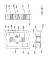
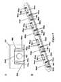
- FIG. 1Aillustrates a top view, a longitudinal cross-sectional view, and a transverse cross-sectional view of an example of a bone plate having a rivet paired with symmetrically arranged elastic segments and a non-circular, quasi-rectangular through hole, in accordance with various embodiments;
- FIG. 1Billustrates bottom, perspective and side views of an example of a rivet for use with the bone plate illustrated in FIG. 1A , wherein the rivet has a generally circular head and a threaded, non-circular expansion portion, in accordance with various embodiments;
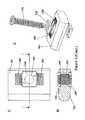
- FIG. 2Aillustrates a perspective assembly view of a bone plate having a rivet, a locking screw, and a plate section with symmetrically arranged elastic segments, in accordance with various embodiments;
- FIG. 2Billustrates a partial perspective assembly view of the bone plate illustrated in FIG. 2A , having a rivet, a locking screw, and a plate section with symmetrically arranged elastic segments, in accordance with various embodiments;
- FIG. 2Cillustrates a top view of a bone plate having a rectangular rivet, a screw, and a plate section with symmetrically arranged elastic segments flanking the screw receiving hole on either side, in accordance with various embodiments;
- FIG. 2Dillustrates a cross-sectional view of the bone plate of FIG. 2C , in accordance with various embodiments
- FIG. 2Eillustrates an exploded perspective view of the bone plate of FIG. 2C , in accordance with various embodiments
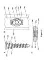
- FIG. 3Aillustrates a side view of an example of a screw with a thread that has a consistent core diameter, but an increased outer diameter in the vicinity of the screw head, in accordance with various embodiments;
- FIG. 3Billustrates a top view of a bone plate having a corresponding thread in the plate hole that extends across the motion gap into the plate, in accordance with various embodiments
- FIG. 3Cillustrates a transverse cross-sectional view of a bone plate having a corresponding thread in the plate hole that extends across the motion gap into the plate, in accordance with various embodiments
- FIG. 4Aillustrates a perspective assembly view of an embodiment of a bone plate assembly that limits deflection of the screw hole member out of the plane of the plate, while allowing for a controlled amount of translation of the screw hole member in the direction of the plate longitudinal axis, in accordance with various embodiments;
- FIG. 4Billustrates a transverse cross-sectional view of the bone plate assembly illustrated in FIG. 4A , showing that the threaded feature of the screw head extends across the motion gap and into the plate to limit deflection of the screw hole member out of the plane of the plate, while allowing for a controlled amount of translation of the screw hole member in the direction of the plate longitudinal axis, in accordance with various embodiments;
- FIG. 4Cillustrates a partial longitudinal perspective view of the bone plate assembly illustrated in FIG. 4A , in accordance with various embodiments;
- FIG. 4Dillustrates a partial transverse perspective view of the bone plate assembly illustrated in FIG. 4A , in accordance with various embodiments;
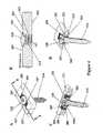
- FIG. 5Aillustrates a top view of an example of a bone plate in which the motion gaps adjacent to the screw hole diverge from the top surface to the lower surface of the plate, in accordance with various embodiments
- FIG. 5Billustrates a bottom view of the bone plate shown in FIG. 5A , in accordance with various embodiments
- FIG. 5Cillustrates a perspective view of the bone plate shown in FIG. 5A , in accordance with various embodiments
- FIG. 5Dillustrates a transverse cross-sectional view of the bone plate shown in FIG. 5A , in accordance with various embodiments
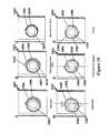
- FIG. 6Aillustrates a top view of another example of a bone plate for elastic fixation of a bone fracture, in accordance with various embodiments
- FIG. 6Billustrates a top view of another bone plate for elastic fixation of a bone fracture for use in combination with cylindrical bone segments, in accordance with various embodiments
- FIG. 7Aillustrates a top view and a cross-sectional side view of an example of a bone plate for elastic fixation of a bone, shown in functional but unloaded association with a bone screw affixed to a cylindrical bone, in accordance with various embodiments;
- FIG. 7Billustrates a top view and a cross-sectional side view of an example of a bone plate for elastic fixation of a bone, shown in functional loaded association with a bone screw affixed to a cylindrical bone, in accordance with various embodiments;
- FIG. 8Aillustrates a top view of an embodiment of a C-shaped flexible element, in accordance with various embodiments
- FIG. 8Billustrates a top view of another embodiment of a C-shaped flexible element wherein elastic beam elements are narrow to reduce stiffness, in accordance with various embodiments
- FIG. 8Cillustrates a top view of another embodiment of a C-shaped flexible element wherein the elastic beam elements are elongated to reduce stiffness, in accordance with various embodiments;
- FIG. 8Dillustrates a top view of an E-shaped flexible element wherein elastic beam elements are narrow to reduce stiffness, in accordance with various embodiments
- FIG. 8Eillustrates a top view of a flexible element that includes one E-shaped slot in combination with multiple linear slots, in accordance with various embodiments
- FIG. 9Aillustrates a top view of a flexible element that includes a curvilinear E-shaped slot in combination with multiple linear slots, in accordance with various embodiments
- FIG. 9Billustrates a perspective view of a bone plate for elastic fixation of a bone fracture, incorporating the flexible elements shown in FIG. 9A , in accordance with various embodiments;
- FIG. 10Aillustrates a top view of a flexible element that includes a single spiral-shaped slot, in accordance with various embodiments
- FIG. 10Billustrates a top view of a flexible element that includes a single spiral-shaped slot with curvilinear and round elements on the outside and inside spiral ends, respectively, in accordance with various embodiments;
- FIG. 10Cillustrates a top view of a flexible element that includes a single spiral-shaped slot having a thin beam, in accordance with various embodiments
- FIG. 10Dillustrates a top view of a flexible element that includes a pair of interlaced spiral-shaped slots, wherein the flexible element is offset from the midline of the bone plate, in accordance with various embodiments;
- FIG. 10Eillustrates a top view of a flexible element that includes a pair of interlaced spiral-shaped slots, wherein the flexible element is positioned at the midline of the bone plate, in accordance with various embodiments;
- FIG. 10Fillustrates a top view of a flexible element that includes three interlaced spiral-shaped slots, in accordance with various embodiments
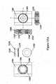
- FIG. 11Aillustrates a side view of a bone plate wherein the flexible element is a separate, removable element that is configured to be inserted into an enlarged receiving hole, in accordance with various embodiments;
- FIG. 11 Billustrates a top view of the flexible element of FIG. 11A , in accordance with various embodiments
- FIG. 11Cillustrates a perspective view of the flexible element of FIG. 11A wherein the flexible element is a separate, removable element that is configured to be inserted into an enlarged receiving hole, in accordance with various embodiments;
- FIG. 12illustrates a cross-sectional perspective view of a flexible element, showing the ratio of beam width to plate height, in accordance with various embodiments
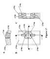
- FIG. 13Aillustrates several views of a flexible element coupled with a rivet configured to protect the flexible element from excessive deformation perpendicular to the plane of the plate, in accordance with various embodiments;
- FIG. 13Billustrates several views of a flexible element coupled with a half-rivet configured to protect the flexible element from excessive deformation perpendicular to the plane of the plate, in accordance with various embodiments;
- FIG. 13Cillustrates a perspective view of a half rivet configured to protect the flexible element from excessive deformation perpendicular to the plane of the plate, wherein the half-rivet is coupled with a customized bone screw, in accordance with various embodiments;
- FIG. 14Aillustrates a cross-sectional view of a rivet elastically suspended inside a receiving hole in a bone plate using a discrete spring element, in accordance with various embodiments
- FIG. 14Billustrates a perspective view of a rivet elastically suspended inside a receiving hole in a bone plate using a discrete spring element, in accordance with various embodiments
- FIG. 15Aillustrates a transverse cross-sectional view of a threaded insert that is suspended with spring elements in a central position within a receiving hole, whereby the spring elements are rigidly coupled to or part of a threaded insert, in accordance with various embodiments;
- FIG. 15Billustrates a top view of the device shown in FIG. 15A , in accordance with various embodiments
- FIG. 15Cillustrates a partial cutaway view of the device shown in FIG. 15A , showing placement of an insert, in accordance with various embodiments;
- FIG. 15Dillustrates a planar cross-sectional view of the device shown in FIG. 15A , in accordance with various embodiments;
- FIG. 16Aillustrates a top view of a threaded insert that is generated from the bone plate by introducing a slot that circumscribes the receiving hole, in accordance with various embodiments
- FIG. 16Billustrates a schematic view of the device shown in FIG. 16A , in accordance with various embodiments
- FIG. 16Cillustrates a longitudinal cross-sectional view of the device shown in FIG. 16A , in accordance with various embodiments;
- FIG. 16Dillustrates a transverse cross-sectional view of the device shown in FIG. 16A , in accordance with various embodiments
- FIG. 17Aillustrates a transverse cross-sectional view of a threaded insert formed by the introduction of a slot that circumscribes the receiving hole in an antiparallel manner and suspended (centered) inside a bone plate using flexible elements, in accordance with various embodiments;
- FIG. 17Billustrates a top view of the device illustrated in FIG. 17A , in accordance with various embodiments
- FIG. 17Cillustrates a longitudinal cross-sectional view of the device illustrated in FIG. 17A , in accordance with various embodiments;
- FIG. 18Aillustrates a cross-sectional side view of a bone plate for elastic fixation of a bone fracture, shown in functional but unloaded association with locking bone screws for spanning a bone fracture in a cylindrical bone, in accordance with various embodiments;
- FIG. 18Billustrates a cross-sectional side view of a bone plate for elastic fixation of a bone fracture, shown in functional association with locking bone screws for spanning a bone fracture in a cylindrical bone, wherein axial compression of the cylindrical bone segments induces parallel motion at the fracture, in accordance with various embodiments;
- FIG. 19Aillustrates a cross-sectional side view of a bone plate for elastic compression of a bone fracture, shown in functional association with non-locking bone screws for spanning a bone facture in a cylindrical bone, wherein bone screws are inserted in an eccentric manner, in accordance with various embodiments;
- FIG. 19Billustrates a cross-sectional side view of a bone plate for elastic compression of a bone fracture, wherein tightening of eccentrically inserted bone screws induces elastic compression across a bone fracture by deformation of elastic beam elements that connect the plate holes to the plate member, in accordance with various embodiments;
- FIG. 20is a graph comparing axial stiffness of a standard plate with that of a plate with spring elements (“S-Plate”) in accordance with embodiments herein.
- Coupledmay mean that two or more elements are in direct physical or electrical contact. However, “coupled” may also mean that two or more elements are not in direct contact with each other, but yet still cooperate or interact with each other.
- a phrase in the form “A/B” or in the form “A and/or B”means (A), (B), or (A and B).
- a phrase in the form “at least one of A, B, and C”means (A), (B), (C), (A and B), (A and C), (B and C), or (A, B and C).
- a phrase in the form “(A)B”means (B) or (AB) that is, A is an optional element.
- the systems and platesmay provide elastic suspension of receiving holes relative to an osteosynthesis plate.
- this elastic suspensionmay promote load distribution between screws that connect a bone segment to the plate, thereby reducing stress risers and the load shielding effect.
- stress at the screw holes, and within the construct as a wholemay be reduced by incorporation of these elastic elements in the plate.
- elastic suspension of the receiving holes relative to the osteosynthesis platemay enable small, controlled amounts of relative motion between bone fragments connected by the plate, which may promote fracture healing by callus formation.
- relative motion between bone fragments enabled by the elastic elementsmay be substantially parallel to an upper or lower surface of the bone plate, or substantially parallel to a bone surface.
- bone plates in accordance with certain embodiments disclosed hereinmay be configured to be suspended above the surface of the bone, so that a gap is present between the lower surface of the plate and the upper surface of the bone. In various embodiments, this may be accomplished by using locking screws that are designed to engage with a threaded hole in the bone plate. In various embodiments, the coupling of a locking screw with a corresponding portion of a bone plate may ensure that the locking screw is only inserted to a certain extent, for instance the point where the screw locks into the hole of the bone plate. In another embodiment, the receiving hole elements may extend through the lower surface of the bone plate, for instance so that the plate remains suspended over the bone surface even if a bone fastener is used to compress the receiving hole element to the one bone.
- elastic suspension of the receiving holes relative to the osteosynthesis platemay promote elastic compression across a fracture site, whereby the plate may be affixed to the bone with non-locking screws inserted in an eccentric manner in order to induce compression across the fracture.
- itmay be beneficial and desirable to stabilize a bone fracture with a plate as disclosed herein to enhance load distribution between screws, to promote fracture site motion when fracture healing by callus formation is desired, and/or to induce prolonged compression across a fracture when direct fracture healing is desired.
- FIG. 1Aillustrates a top view, a longitudinal cross-sectional view, and a transverse cross-sectional view of a specific, non-limiting example of a bone plate having a rivet paired with symmetrically arranged elastic segments and a non-circular, quasi-rectangular through hole
- FIG. 1Billustrates bottom, perspective and side views of an example of a rivet for use with the bone plate illustrated in FIG. 1A , wherein the rivet has a generally circular head and a threaded, non-circular expansion portion
- FIGS. 2A and 2Billustrate a perspective assembly view and a cross-sectional assembly view of a bone plate having a rivet, a locking screw, and a plate section with symmetrically arranged elastic segments, all in accordance with various embodiments.
- the bone plate 101may include a rivet 160 with generally symmetrically-arranged elastic segments 108 and a non-circular, quasi-rectangular through hole 136 .
- elastic segmentsalso referred to herein as elastic elements, elastic beam elements, and spring elements
- screw hole member 105 amay include quasi-rectangular through hole 136 .
- a lower rivet member 160 with a rivet head 148 and a rectangular expansion element 168may be inserted from the lower plate surface 103 into rectangular through hole 136 of screw hole member 105 a.
- rivet 160may be secured in screw hole member 105 a by press-fit, whereas in other embodiments, rivet 160 may be secured in screw hole member 105 a using a retaining feature that may be adapted to engage with a corresponding receiving feature in quasi-rectangular through hole 136 .
- rivet head 148may be sufficiently large to extend laterally across the motion gap 107 of elastic segments 108 .
- rivet 160may be configured to protect elastic segments 108 from excessive deformation perpendicular to the plane of plate 101 .
- the circular through-hole 105 of rivet 160may be threaded, and the threads may extend into quasi-rectangular through hole 136 of screw hole member 105 a.
- a screw 110 with matching threadsmay be inserted from the upper plate surface 102 through the rivet 160 , and the screw locking feature 109 may be sufficiently large to extend laterally across motion gap 107 of elastic segments 108 .
- the screw locking feature 109may therefore limit deflection of screw hole member 105 a toward lower plate surface 103 .
- the rivet head 148may limit deflection of screw hole member 105 a toward upper plate surface 102 .
- the illustrated examplemay enable controlled translation of screw hole member 105 a relative to the longitudinal axis of the plate, yet may limit translation relative to the plane of bone plate 101 when screw hole member 105 a is guided between the screw locking feature 109 and rivet head 148 .
- FIGS. 2C , 2 D, and 2 Eillustrate a top view ( FIG. 2C ), a cross-sectional view FIG. 2D ), and an exploded perspective view ( FIG. 2E ) of a bone plate having a rectangular rivet 260 , a screw 210 , and a plate 201 with generally symmetrically arranged elastic segments 208 flanking the screw receiving hole on either side, all in accordance with various embodiments.
- rivet 260may have a rectangular or square shape, and may be recessed into the top and or bottom surfaces of bone plate 201 .
- rivet 260may include a separate center shaft portion 268 , and one or two shoulder portions 248 coupled thereto.
- the upper and/or lower shoulder portions 248 of rivet 260may limit translation of receiving hole 205 in a direction that is substantially perpendicular to the upper or lower plane of bone plate 201 .
- rivet 260may constrain out-of-plane motion, while still allowing axial (e.g., in-plane) translation of receiving hole 205 relative to bone plate 201 (or vice versa).
- screw 210may be a locking screw, for instance, a screw having a threaded head portion, or it may be a non-locking screw.
- a non-locking screwmay compress shoulder portions 248 and center shaft portion 268 of rivet 260 onto the bone, while plate 201 may retain an axially flexible connection with the bone via elastic segments 208 .
- FIGS. 3A , 3 B, and 3 Cillustrate a side view, a top view, and a transverse cross-sectional view, respectively, of an example of a screw with a thread that has a consistent core diameter, but an increased outer diameter in vicinity of the screw head, and FIGS.
- 4A , 4 B, 4 C, and 4 Dillustrate a perspective assembly view, a transverse cross-sectional view, a partial longitudinal perspective view, and a partial transverse perspective view, respectively, of an embodiment of a bone plate assembly 301 , showing that the threaded feature of the screw head extends across the motion gap and into the plate to limit deflection of the screw hole member out of the plane of the plate, while allowing for a controlled amount of translation of the screw hole member in the direction of the plate longitudinal axis, all in accordance with various embodiments.
- a bone plate in accordance with the present disclosuremay include elastic segments 308 that may be symmetrically arranged in proximity with the screw hole 305 , for instance to enable translation of the screw hole member 305 a in a principally axial direction.
- screw hole member 305 amay be guided to remain within the plane of the plate by a thread 321 that may extend from screw hole 305 , across the motion gap 307 , and into the plate member 301 .
- thread 321may be characterized by an outer diameter that is considerably larger than the core diameter. For example, a suitable core diameter is in the range of 2 to 5 and a suitable outer diameter is in the range of 4 to 10.
- the locking screw 310may include a correspondingly threaded head segment 318 with an outer diameter that is considerably larger than the core diameter.
- the outer diameter of the thread 319 of the screw head segment 318may be smaller than the outer diameter of thread 321 in screw hole member 305 a.
- the outer diameter of thread 319 in screw head segment 318may remain large enough to extend across the motion gap 307 and into the plate member 301 , once inserted into the screw hole 305 .
- screw head 328may include a locking feature 309 at may enable rigid fixation of screw head 328 inside screw hole member 305 a.
- screw hole member 305 amay translate in a principally axial direction relative to the plate longitudinal axis, for instance, due to the difference in outer diameters between screw head 328 , thread 319 , and plate thread 321 .
- extension of screw head thread 319 across motion gap 307 and into plate member 301may limit deflection of screw hole member 305 a outside the plane of plate 301 .
- FIGS. 5A , 5 B, 5 C, and 5 Dillustrate a top view, a bottom view, a perspective view, and a transverse cross-sectional view, respectively, of an example of a bone plate 501 in which the motion gaps 507 adjacent to the screw hole 505 diverge from the top surface 502 to the lower surface 503 of plate 501 , in accordance with various embodiments.
- elastic segments 508may be symmetrically arranged in proximity with screw hole 505 , for instance, to enable translation of the screw hole member 505 a in a principally axial direction.
- motion gaps 507 connecting symmetrically arranged elastic segments 508may diverge from (angle away from) the upper plate surface 502 toward the lower plate surface 503 .
- these divergent motion gaps 507may limit deflection of screw hole member 505 a through upper surface 502 of the plate member 501 .
- the head diameter of the corresponding locking screw 510may be sufficiently large to extend over motion gap 507 on upper surface 502 of plate member 501 .
- the headmay extend over motion gap, when at rest, by about 0.1 mm-3 mm, for example, about 1 mm.
- the locking feature 509may thereby limit deflection of screw hole member 505 a through bottom surface 503 of plate member 501 .
- FIG. 6Aillustrates a top view of another example of a bone plate for elastic fixation of a bone fracture
- FIG. 6Billustrates a top view of a further bone plate for elastic fixation of a bone fracture for use in combination with cylindrical bone segments
- the bone plate 601may have an upper surface 602 and a bone contacting surface 603 , and it may define a longitudinal axis 604 .
- at least one receiving hole 605 for a fixation elementmay extend through the upper surface 602 and the bone contacting surface 603 .
- receiving hole 605may be threaded for rigid engagement of a locking screw with a threaded head portion, or it may have a concave recess to accommodate a conventional compression screw. In some embodiments, receiving holes 605 may be disposed along the longitudinal axis 604 as shown in FIG. 6A . In other embodiments, receiving holes 605 may be spaced from the longitudinal axis 604 , as shown in FIG. 6B .
- receiving hole 605in the vicinity of receiving hole 605 are one or more slots 606 extending from the upper surface 602 to the bone contacting surface 603 .
- at least one substantially C-shaped, E-shaped, or semi-circular slot 606may extend around a substantial portion of receiving hole 605 .
- a corresponding slot 606 amay extend from the opposite side of the periphery around receiving hole 605 .
- the end segments of slot 606may overlap, but not intersect the end segments of corresponding slot 606 a.
- the overlapping slots 606 and 606 amay enclose elastic beam elements (e.g., spring elements) 608 that may enable elastic translation of receiving hole 605 relative to bone plate 601 in a direction principally parallel to the longitudinal axis 604 of bone plate 601 .
- elastic beam elementse.g., spring elements
- elastic beam elements 608may be formed by combining at least one substantially C-shaped, E-shaped or semi-circular slot 606 with one or more substantially linear slots 606 a extending from the periphery of bone plate 601 in an essentially perpendicular manner to overlap but not intersect with the ends of slots 606 .
- FIGS. 7A and 7Billustrate top and cross-sectional side views of an example of a bone plate 701 for elastic fixation of a bone, shown in functional but unloaded ( FIG. 7A ) association with a bone screw 710 affixed to a cylindrical bone 726 , and shown in functional loaded ( FIG. 7B ) association with a bone screw 710 affixed to a cylindrical bone, in accordance with various embodiments.
- a locking bone screw 710is illustrated that may have a threaded head segment 718 for rigid engagement with receiving hole 705 .
- the screw 710may be furthermore engaged in first cortex 713 and/or second cortex 714 of a substantially cylindrical bone 726 .
- FIG. 7Aillustrates an example of an unloaded construct
- FIG. 7Billustrates an example of how a load acting through bone 726 and onto locking screw 710 may induce translation of receiving hole 705 relative to the bone plate 701 by elastic deformation of elastic beam elements 708 between receiving hole 705 and bone plate 701 .
- the dimensions and/or the configuration of the spring elements (e.g., elastic beam elements) and/or slotsmay be varied in order to achieve a desired stiffness and range of elastic displacement of the bone plate relative to the receiving holes.
- FIG. 8Adepicts an embodiment with thicker beam elements 808 as compared to beam elements 808 shown in FIG. 8B , the latter allowing for more flexible displacement of receiving hole 805 relative to bone plate member 801 .
- FIG. 8CAnother example of a way to decrease the stiffness of the elastic elements is depicted in FIG. 8C , wherein the length of slot 806 is increased in order to increase the effective length of beam elements 808 .
- Yet another example of a way to decrease the stiffness of the elastic elementis depicted in FIG.
- slots 806are configured in a substantially E-shaped formation, which may yield an increased effective length of elastic beam elements 808 .
- FIG. 8EAnother alternative embodiment of an elastic element is depicted in FIG. 8E , wherein receiving hole 805 is located in vicinity of plate edge 823 .
- two slots 806may overlap but not intersect each end of a C-shaped slot 806 to form elastic beam elements 808 .
- FIG. 9Aillustrates a top view of a flexible element that includes a curvilinear E-shaped slot in combination with multiple linear slots 906
- FIG. 9Billustrates a perspective view of a bone plate 901 for elastic fixation of a bone fracture that incorporates the flexible elements 908 shown in FIG. 9A , in accordance with various embodiments.
- some embodiments of bone plates 901may include one curvilinear E-shaped slot 906 b in combination with multiple linear slots 906 a, which together form elastic beam elements 908 .
- the curvilinear slots 906 amay reduce peak stress and provide a more even strain distribution when loaded along the longitudinal axis of a bone plate 901 .
- each of the two folded elastic beams 908 associated with a receiving hole 905may be oriented in opposite directions, wherein the folded end of one elastic beam element 908 may be oriented toward the edge of the bone plate 901 , and the folded end of the other elastic beam element may be oriented toward the bone plate 901 midline.
- the curvilinear fold of the elastic beam element 908may fit closely within the E-shaped slot 906 b, which arrangement may contribute to a stable association of receiving hole 905 with plate 901 , while still allowing for controlled axial translation of receiving hole 905 relative to plate 901 .
- FIG. 9Billustrates a perspective view of a bone plate having the curvilinear E-shaped slots 906 b shown in FIG. 9 k
- the receiving holes 905may be offset from the longitudinal axis, which may contribute to the stability and stiffness of bone plate 901 .
- FIG. 10Aillustrates a top view of a flexible element that includes of a single spiral-shaped slot 1006
- FIG. 10Billustrates a top view of a flexible element that includes a single spiral-shaped slot 1006 with curvilinear 1016 and round elements 1018 on the outside and inside spiral ends, respectively
- FIG. 10Cillustrates a top view of a flexible element that includes a single spiral-shaped slot 1006 having a thin elastic beam element 1008
- FIG. 10Dillustrates a top view of a flexible element that includes a pair of interlaced spiral-shaped slots 1006 , wherein the flexible element is offset from the midline of the bone plate 1001
- FIG. 10Aillustrates a top view of a flexible element that includes of a single spiral-shaped slot 1006
- FIG. 10Billustrates a top view of a flexible element that includes a single spiral-shaped slot 1006 with curvilinear 1016 and round elements 1018 on the outside and inside spiral ends, respectively
- FIG. 10Cillustrates a top view
- FIG. 10Eillustrates a top view of a flexible element that includes a pair of interlaced spiral-shaped slots 1006 , wherein the flexible element is positioned at the midline of the bone plate 1001
- FIG. 10Fillustrates a top view of a flexible element that includes three interlaced spiral-shaped slots 1006 , all in accordance with various embodiments.
- FIG. 10Adepicts another embodiment of an elastic element.
- a single spiral-shaped slot 1006may be positioned around receiving hole 1005 .
- the spiral slot 1006may circumscribe receiving hole 1005 once or multiple times, creating elastic beam element 1008 where it overlaps.
- circular 1018 or curvilinear 1016 elementsmay be added to the ends of slot 1006 as shown in FIG. 10B , or the beam elements 1008 may be tapered.
- beam elements 1008may be configured to be thinner, as shown in FIG. 10C , allowing for more flexible displacement of receiving hole 1005 relative to bone plate member 1001 .
- increasing the length of spiral beam element 1008also may allow for increased flexibility.
- receiving holes 1005may be located along the midline of plate 1001 , or at a distance from the longitudinal axis of plate 1001 .
- receiving holes 1006may be arranged in an alternating staggered pattern relative to the longitudinal midline of plate 1001 , they may provide multi-planar fixation to improve the strength of the fixation between plate 1001 and the underlying bone.
- FIGS. 10D and 10Eillustrate spiral slots 1006 that include two interlaced spirals.
- additional spiral slots 1006may be used, such as the three-slot 1006 arrangement depicted in FIG. 10F .
- FIGS. 11A , 11 B, and 11 Cillustrate three views of another embodiment of a flexible element.
- slot 1106 and elastic beam element 1108may be located on a separate, removable plug element 1120 that may be adapted to be inserted into an enlarged receiving hole 1136 .
- removable plug element 1120may be an integral component of an enlarged head of a bone screw that engages the correspondingly enlarged receiving hole 1136 .
- FIG. 12depicts a cross-sectional perspective view of another embodiment, showing the dimensions of beam element 1208 and slot 1206 .
- beam elements 1208may be considerably higher (thicker) than they are wide.
- the ratio of the beam height 1264 to the beam width 1266may vary from about 2 (2 to 1) to about 12 (12 to 1), for instance from about 6 (6 to 1) to about 9 (9 to 1).
- receiving holes 1205 associated with flexible elements as described hereinmay or may not have features for positive locking of a bone screw or fastener.
- the flexible spring elementmay act to relieve stress at the plate-bone interface.
- the flexible elementmay provide flexible plate fixation to allow small relative motion between the plate and the bone, which in turn may induce interfragmentary motion and promote bone healing.
- FIG. 13Aillustrates several views of a flexible element 1308 used in conjunction with a rivet 1340 configured to protect the flexible element 1308 from excessive deformation perpendicular to the plane of the plate 1301
- FIG. 13Billustrates several views of a flexible element 1308 used in conjunction with a half-rivet 1360 configured to protect the flexible element 1308 from excessive deformation perpendicular to the plane of the plate 1301
- FIG. 13Cillustrates a perspective view of a half rivet 1360 configured to protect the flexible element 1308 from excessive deformation perpendicular to the plane of the plate 1301 , wherein the half-rivet 1360 is used together with a customized bone screw 1310 , all in accordance with various embodiments.
- the elastic element 1308may include a spiral-shaped slot 1306 positioned around receiving hole 1305 , and the spiral slot 1306 may circumscribe receiving hole 1305 once or multiple times, creating elastic beam element 1308 where it overlaps.
- a rivet 1338may be provided in receiving hole 1305 , and may be configured to protect elastic beam element 1308 from excessive deformation perpendicular to the plane of plate 1301 .
- rivet 1338may have a shoulder 1348 on each side of a central cylinder 1340 to restrict flexion of elastic beam element 1308 that may occur within the plane of plate 1301 .
- the inner diameter of the central cylinder 1340 of rivet 1338may be threaded for rigid locking with the threaded head of a bone screw 1310 .
- the rivet shoulders 1348may rest on the surface of the plate 1301 , or may be recessed into the plate 1301 .
- the longitudinal dimension of the recessmay be larger than the corresponding dimension of rivet shoulder 1348 to allow rivet translation along the plate 1301 longitudinal axis, while constraining rivet 1338 translation in a transverse direction.
- rivet 1338may include two parts that may be inserted from opposite sides into receiving hole 1305 , and the two parts may be rigidly coupled to each other, for instance by laser welding or by a thread feature between central cylinder 1340 and shoulder 1348 .
- rivet 1338may have only one shoulder 1348 to form a “half-rivet” 1360 , which may limit deformation of elastic beam element 1308 in only one direction.
- half-rivet 1360may include an externally threaded central cylinder 1340 for rigid engagement to elastic beam element 1308 .
- half-rivet 1360may be attached to elastic beam element 1308 using a press fit between central cylinder 1340 and elastic beam element 1308 .
- half-rivet 1360may be used in combination with a customized bone screw 1310 as shown in FIG. 13C , which may include a head that incorporates a corresponding shoulder element 1362 .
- elastic beam element 1308upon screw insertion, elastic beam element 1308 may be confined between shoulder 1348 of half-rivet 1360 and the corresponding shoulder 1362 of the screw head, with the remainder of the screw head resting inside central cylinder 1340 of half-rivet 1360 .
- rivet 1438may be elastically suspended inside receiving hole 1436 using a discrete spring element 1458 .
- spring element 1458may include a corrugated metal strip 1444 , that may circumscribe central cylinder 1440 of rivet 1438 , and that may center rivet 1438 inside receiving hole 1436 , while allowing for elastic translation of rivet 1438 within the plane of plate 1401 .
- spring element 1458may further retain rivet 1438 inside the plane of plate 1401 .
- the inner diameter of central cylinder 1440 of rivet 1438may be threaded in some embodiments for rigid locking with the threaded head of a bone screw.
- FIGS. 15 A, 15 B, 15 C, and 15 Dillustrate a cross-sectional view, a top view, a partial cutaway view showing placement of an insert 1546 , and a planar cross-sectional view, respectively, of another embodiment, in which a threaded insert 1546 , once inserted into insert receiving hole 1536 , may translate along the longitudinal plate axis within the plane of plate 1501 .
- threaded insert 1546may be suspended with spring elements (e.g., flexible elements) 1548 in a central position within insert receiving hole 1536 , whereby spring elements (e.g., flexible elements) 1548 may be rigidly coupled to or part of threaded insert 1546 .
- threaded insert 1546may have a convex cylindrical surface 1550 adapted to securely retain threaded insert 1546 within the plane of plate 1501 .
- threaded insert 1546may be first rotated perpendicular to the plate surface, then inserted into insert receiving hole 1536 , and finally rotated by 90 degrees so that its upper surface is parallel to the upper surface of plate 1501 .
- spring elements (e.g., flexible elements) 1548may engage with (e.g., snap into) a corresponding recess 1542 in plate 1501 to ensure that upon insertion, threaded insert 1546 remains rotationally secured within the plane of plate 1501 .
- FIG. 16Aillustrates a top view of a threaded insert 1646 that is generated from the bone plate 1601 by introducing a slot 1606 that circumscribes the receiving hole 1605
- FIG. 16Billustrates a schematic view of the device shown in FIG. 16A
- FIG. 16Cillustrates a longitudinal cross-sectional view of the device shown in FIG. 16A
- FIG. 16Dillustrates a transverse cross-sectional view of the device shown in FIG. 16A , all in accordance with various embodiments.
- a threaded insert 1646may be generated from plate 1601 by introducing a slot 1606 that circumscribes receiving hole 1605 .
- slot 1606may be introduced in an anti-parallel manner, whereby two opposing sections 1652 of slot 1606 converge toward the lower side 1603 of plate 1601 , while two other opposing sections 1654 diverge toward the lower side 1603 of plate 1601 .
- the anti-parallel slot 1606may enable threaded insert 1646 to translate relative to plate 1601 within the confines of the slot width, and without being able to disassociate from plate 1601 .
- FIG. 17Aillustrates a transverse cross-sectional view of a threaded insert 1746 formed by the introduction of a slot 1706 that circumscribes the receiving hole 1705 in an anti-parallel manner and suspended (centered) inside a bone plate 1701 using flexible elements 1758
- FIG. 17Billustrates a top view of the device illustrated in FIG. 17A
- FIG. 17Cillustrates a longitudinal cross-sectional view of the device illustrated in FIG. 17A , all in accordance with various embodiments. As illustrated in FIGS.
- threaded insert 1746may be formed by the introduction of a slot 1706 that circumscribes receiving hole 1705 in an antiparallel manner as described above, and threaded insert 1746 may be suspended (centered) inside plate 1701 using flexible elements 1758 .
- these flexible elements 1758may be cylindrical in shape and comprised of a polymer, and may provide a flexible connection between threaded insert 1746 and plate 1701 , while the anti-parallel slot ensures that threaded insert 1746 remains securely captured in plate 1701 .
- FIG. 18Aillustrates a cross-sectional side view of a bone plate for elastic fixation of a bone fracture, shown in functional but unloaded association with locking bone screws for spanning a bone fracture in a cylindrical bone
- FIG. 18Billustrates a cross-sectional side view of a bone plate for elastic fixation of a bone fracture, shown in functional association with locking bone screws for spanning a bone fracture in a cylindrical bone, wherein axial compression of the cylindrical bone segments induces parallel motion at the fracture, both in accordance with various embodiments.
- FIG. 18Adepicts a cross-sectional view of an embodiment for elastic fixation of a bone fracture 1824 with a bone plate 1801 that may be attached to two bone segments 1826 .
- each bone segment 1826may be connected by one or more locking bone screws 1810 to receiving holes 1805 that may be connected with elastic elements 1808 to bone plate 1801 .
- the screw heads 1828 of bone screws 1810may be rigidly connected to receiving holes 1805 , for instance by matching thread features on screw heads 1828 with those on the receiving holes 1805 .
- this locking mechanism between screw heads 1828 and receiving holes 1805may enable bone plate 1801 to remain elevated above bone surface 1830 , while providing elastic fixation between bone segments 1826 .
- FIG. 18Bdepicts a cross-sectional view of an embodiment for elastic fixation of a bone fracture subjected to axial loading, as may be the case in patients that start weight bearing of a fractured extremity that has been stabilized with bone plate 1801 .
- the load acting on bone segments 1826 and onto locking screws 1810may induce elastic translation of receiving holes 1805 relative to bone plate 1801 , which in turn may cause generally parallel motion between bone segments 1826 at bone fracture 1824 .
- axial loading of bone segments 1826may cause elastic deformation of elastic beam elements 1808 , wherein slot segments 1832 located at the aspect of receiving hole 1805 facing fracture 1824 become narrower, while slot segments 1834 located at the receiving hole aspect facing away from fracture 1824 become wider.
- FIG. 19Aillustrates a cross-sectional side view of a bone plate for elastic compression of a bone fracture, shown in functional association with non-locking bone screws for spanning a bone facture in a cylindrical bone, wherein bone screws are inserted in an eccentric manner
- FIG. 19Billustrates a cross-sectional side view of a bone plate for elastic compression of a bone fracture, wherein tightening of eccentrically inserted bone screws induces elastic compression across a bone fracture by deformation of elastic beam elements that connect the plate holes to the plate member, both in accordance with various embodiments.
- FIGS. 19A and 19Bdepict cross-sectional views of an embodiment of a bone plate 1901 applied to bridge and to elastically compress a fracture 1924 in a substantially cylindrical bone.
- FIG. 19Adepicts bone screws 1910 being partially inserted through receiving holes 1905 into bone segments 1926 .
- screws 1910may be inserted eccentrically in receiving holes 1905 , at a small distance from the center-line 1922 of receiving hole 1905 in an opposite direction from fracture 1924 .
- FIG. 19Bdepicts the embodiment in a cross-sectional view after complete insertion of screws 1910 .
- screws 1910may be forced to translate toward the center of receiving holes 1905 . This in turn causes bone segment 1926 attached to screws 1910 to translate relative to bone plate 1901 toward fracture 1924 , thereby inducing compression across fracture 1924 . Once fracture 1924 is fully compressed, any further translation may be accommodated by deformation of elastic beam elements 1908 connecting receiving holes 1905 to bone plate 1901 . In embodiments, this elastic deformation may induce additional compressive forces at fracture 1924 .
- the introduction of elastic elements in a bone plate as described elsewhere hereinmay reduce axial stiffness of the plate as compared to a standard plate without the elastic elements. Notably, there is little to no impact on the bending stiffness of the plate due to the introduction of the elastic elements.
- having an opening with a major dimension in a transverse directionmay effectively reduce the bending strength of bone plates, which may fail in bending.
- the flexible elements described hereinmay not have a major dimension extending in transverse direction. This orientation may cause the bone plate to retain a substantial amount of bending strength.
- stress at the screw hole(s)may cause undesirable or detrimental deformation of the hole(s).
- the transverse openingmay extend over a substantial portion of the plate in order to derive flexibility, which in turn may reduce the bending strength of the plate.
- various embodiments disclosed hereinemploy a combination of two or more cantilever beams located above and below the screw hole (e.g., in the longitudinal plate direction), which may preserve bending strength of the plate.
- one or more pairs of cantilever beamsmay be employed, wherein the beams of each cantilever pair are located on opposite sides of the screw hole in longitudinal direction, rather than one cantilever beam element that extends in a principally transverse direction to either one or both sides of the screw hole (lug), depending if the screw hole is located offset from or located on the longitudinal plate midline, respectively.
- Still other embodimentsinclude a set of slots per screw hole, wherein the set combines a central slot that partially surrounds the screw hole without extending through the plate edge with peripheral slots that penetrate through the longitudinal plate edge, rather than one continuous slot per screw hole, whereby the slot defines the transverse opening and surrounds the beam and lug element.
- Various other embodiments disclosed hereinemploy a set of slots to form a principally S-shaped spring element having an upper and a lower cantilever element that is diagonally connected by a central segment that contains the screw hole, rather than a generally I-shaped cantilever beam, for instance.
- Still other embodiments described hereinemploy cantilever elements of a width that is substantially smaller than the plate thickness, rather than a cantilever element of a width that is larger than the plate thickness. This may ensure a desired bending direction of the cantilever beam within the plane of the plate rather than out of the plane of the plate.
Landscapes
- Health & Medical Sciences (AREA)
- Orthopedic Medicine & Surgery (AREA)
- Surgery (AREA)
- Life Sciences & Earth Sciences (AREA)
- Heart & Thoracic Surgery (AREA)
- Nuclear Medicine, Radiotherapy & Molecular Imaging (AREA)
- Engineering & Computer Science (AREA)
- Biomedical Technology (AREA)
- Neurology (AREA)
- Medical Informatics (AREA)
- Molecular Biology (AREA)
- Animal Behavior & Ethology (AREA)
- General Health & Medical Sciences (AREA)
- Public Health (AREA)
- Veterinary Medicine (AREA)
- Surgical Instruments (AREA)
Abstract
Description
Claims (12)
Priority Applications (3)
| Application Number | Priority Date | Filing Date | Title |
|---|---|---|---|
| US13/554,119US8992583B2 (en) | 2010-06-23 | 2012-07-20 | Flexible plate fixation of bone fractures |
| US14/630,938US9763713B2 (en) | 2010-06-23 | 2015-02-25 | Flexible plate fixation of bone fractures |
| US15/684,607US10716605B2 (en) | 2010-06-23 | 2017-08-23 | Flexible plate fixation of bone fractures |
Applications Claiming Priority (4)
| Application Number | Priority Date | Filing Date | Title |
|---|---|---|---|
| US35785510P | 2010-06-23 | 2010-06-23 | |
| US201061428745P | 2010-12-30 | 2010-12-30 | |
| US13/166,539US8882815B2 (en) | 2010-06-23 | 2011-06-22 | Flexible plate fixation of bone fractures |
| US13/554,119US8992583B2 (en) | 2010-06-23 | 2012-07-20 | Flexible plate fixation of bone fractures |
Related Parent Applications (1)
| Application Number | Title | Priority Date | Filing Date |
|---|---|---|---|
| US13/166,539DivisionUS8882815B2 (en) | 2010-06-23 | 2011-06-22 | Flexible plate fixation of bone fractures |
Related Child Applications (1)
| Application Number | Title | Priority Date | Filing Date |
|---|---|---|---|
| US14/630,938ContinuationUS9763713B2 (en) | 2010-06-23 | 2015-02-25 | Flexible plate fixation of bone fractures |
Publications (2)
| Publication Number | Publication Date |
|---|---|
| US20130006310A1 US20130006310A1 (en) | 2013-01-03 |
| US8992583B2true US8992583B2 (en) | 2015-03-31 |
Family
ID=45353264
Family Applications (4)
| Application Number | Title | Priority Date | Filing Date |
|---|---|---|---|
| US13/166,539Active2032-01-23US8882815B2 (en) | 2010-06-23 | 2011-06-22 | Flexible plate fixation of bone fractures |
| US13/554,119ActiveUS8992583B2 (en) | 2010-06-23 | 2012-07-20 | Flexible plate fixation of bone fractures |
| US14/630,938Active2031-07-20US9763713B2 (en) | 2010-06-23 | 2015-02-25 | Flexible plate fixation of bone fractures |
| US15/684,607Active2032-02-17US10716605B2 (en) | 2010-06-23 | 2017-08-23 | Flexible plate fixation of bone fractures |
Family Applications Before (1)
| Application Number | Title | Priority Date | Filing Date |
|---|---|---|---|
| US13/166,539Active2032-01-23US8882815B2 (en) | 2010-06-23 | 2011-06-22 | Flexible plate fixation of bone fractures |
Family Applications After (2)
| Application Number | Title | Priority Date | Filing Date |
|---|---|---|---|
| US14/630,938Active2031-07-20US9763713B2 (en) | 2010-06-23 | 2015-02-25 | Flexible plate fixation of bone fractures |
| US15/684,607Active2032-02-17US10716605B2 (en) | 2010-06-23 | 2017-08-23 | Flexible plate fixation of bone fractures |
Country Status (5)
| Country | Link |
|---|---|
| US (4) | US8882815B2 (en) |
| EP (2) | EP3639775B1 (en) |
| AU (1) | AU2011270934B2 (en) |
| CA (1) | CA2803585C (en) |
| WO (1) | WO2011163387A2 (en) |
Cited By (10)
| Publication number | Priority date | Publication date | Assignee | Title |
|---|---|---|---|---|
| US9295508B2 (en) | 2012-02-03 | 2016-03-29 | Zimmer, Inc. | Bone plate for elastic osteosynthesis |
| US9510879B2 (en) | 2010-06-23 | 2016-12-06 | Zimmer, Inc. | Flexible plate fixation of bone fractures |
| US9763713B2 (en) | 2010-06-23 | 2017-09-19 | Zimmer, Inc. | Flexible plate fixation of bone fractures |
| US10307499B2 (en) | 2011-09-22 | 2019-06-04 | Bürkert Contromatic Corp. | Devices, systems and methods for zone sterilization |
| US10814026B2 (en) | 2011-09-22 | 2020-10-27 | Bürkert Contromatic Corp. | Devices, systems and methods for zone sterilization |
| US10932833B2 (en) | 2015-03-03 | 2021-03-02 | Pioneer Surgical Technology, Inc. | Bone compression device and method |
| US11324538B2 (en) | 2019-12-04 | 2022-05-10 | Biomet Manufacturing, Llc | Active bone plate |
| US11344346B2 (en) | 2018-06-29 | 2022-05-31 | Pioneer Surgical Technology, Inc. | Bone plate system |
| US11877779B2 (en) | 2020-03-26 | 2024-01-23 | Xtant Medical Holdings, Inc. | Bone plate system |
| US11957394B2 (en) | 2020-02-27 | 2024-04-16 | J.M. Longyear Manufacturing, Llc | Screw caddy |
Families Citing this family (38)
| Publication number | Priority date | Publication date | Assignee | Title |
|---|---|---|---|---|
| WO2003068290A2 (en) | 2002-02-11 | 2003-08-21 | Antares Pharma, Inc. | Intradermal injector |
| HUE042286T2 (en) | 2005-01-24 | 2019-06-28 | Antares Pharma Inc | Needle-filled pre-filled syringe |
| WO2007131013A1 (en) | 2006-05-03 | 2007-11-15 | Antares Pharma, Inc. | Two-stage reconstituting injector |
| WO2007131025A1 (en) | 2006-05-03 | 2007-11-15 | Antares Pharma, Inc. | Injector with adjustable dosing |
| EP3636301A1 (en) | 2008-03-10 | 2020-04-15 | Antares Pharma, Inc. | Injector safety device |
| US8376993B2 (en) | 2008-08-05 | 2013-02-19 | Antares Pharma, Inc. | Multiple dosage injector |
| JP5732039B2 (en) | 2009-03-20 | 2015-06-10 | アンタレス・ファーマ・インコーポレーテッド | Hazardous drug injection system |
| KR101781790B1 (en)* | 2010-07-21 | 2017-09-26 | 신세스 게엠바하 | Device for osteosynthesis |
| US9168076B2 (en) | 2011-01-25 | 2015-10-27 | Bridging Medical, Llc | Bone compression screw |
| US8496619B2 (en) | 2011-07-15 | 2013-07-30 | Antares Pharma, Inc. | Injection device with cammed ram assembly |
| US9220660B2 (en) | 2011-07-15 | 2015-12-29 | Antares Pharma, Inc. | Liquid-transfer adapter beveled spike |
| US9522023B2 (en)* | 2011-12-09 | 2016-12-20 | Zimmer Gmbh | Orthopedic plate, orthopedic device, method of coupling bone segments, and method of assembling an orthopedic plate |
| US9107710B1 (en) | 2012-02-02 | 2015-08-18 | Alliance Partners, Llc | Bone fixation assembly |
| US9486583B2 (en) | 2012-03-06 | 2016-11-08 | Antares Pharma, Inc. | Prefilled syringe with breakaway force feature |
| EP4186545A1 (en) | 2012-04-06 | 2023-05-31 | Antares Pharma, Inc. | Needle assisted jet injection administration of testosterone compositions |
| US9364610B2 (en) | 2012-05-07 | 2016-06-14 | Antares Pharma, Inc. | Injection device with cammed ram assembly |
| FI3659647T3 (en) | 2013-02-11 | 2024-03-28 | Antares Pharma Inc | NEEDLE-ASSISTED SPRAY INJECTOR WITH REDUCED TRIGGER FORCE |
| CA2905031C (en) | 2013-03-11 | 2018-01-23 | Hans PFLAUMER | Dosage injector with pinion system |
| WO2014165136A1 (en) | 2013-03-12 | 2014-10-09 | Antares Pharma, Inc. | Constant volume prefilled syringes and kits thereof |
| EP2789303A1 (en)* | 2013-04-12 | 2014-10-15 | Zimmer GmbH | Implantable insert sleeve |
| CN104546101A (en)* | 2013-10-24 | 2015-04-29 | 纪玉清 | Dynamic fixing steel plate for fracture |
| AU2014365821B2 (en) | 2013-12-20 | 2019-10-03 | Crossroads Extremity Systems, Llc | Polyaxial locking hole |
| US9408647B2 (en) | 2014-02-27 | 2016-08-09 | Biomedical Enterprises, Inc. | Method and apparatus for use of a compressing plate |
| JP2017529886A (en) | 2014-07-10 | 2017-10-12 | クロスローズ エクストリミティ システムズ リミテッド ライアビリティ カンパニー | Bone implant and means of insertion |
| US11202626B2 (en) | 2014-07-10 | 2021-12-21 | Crossroads Extremity Systems, Llc | Bone implant with means for multi directional force and means of insertion |
| US9883897B2 (en) | 2014-09-25 | 2018-02-06 | Biomedical Enterprises, Inc. | Method and apparatus for a compressing plate |
| WO2016081528A1 (en) | 2014-11-17 | 2016-05-26 | Bridging Medical, Llc | Bone compression systems |
| WO2017011589A1 (en) | 2015-07-13 | 2017-01-19 | Crossroads Extremity Systems, Llc | Bone plates with dynamic elements |
| CN105213015B (en)* | 2015-11-10 | 2018-05-15 | 张英泽 | A kind of bone plate for having active pressure effect to fracture end |
| US10340803B2 (en)* | 2016-04-22 | 2019-07-02 | Texas Instruments Incorporated | DC-DC converter having predicted zero inductor current |
| CN108210049A (en)* | 2016-12-09 | 2018-06-29 | 上海市浦东医院 | New type auto locking and pressurizing steel plate |
| US11864753B2 (en) | 2017-02-06 | 2024-01-09 | Crossroads Extremity Systems, Llc | Implant inserter |
| EP3579762B1 (en) | 2017-02-07 | 2024-06-26 | Crossroads Extremity Systems, LLC | Counter-torque implant |
| EP4009892B1 (en) | 2019-08-06 | 2025-04-30 | Paragon 28, Inc. | Dynamic bone plate |
| US12059183B2 (en) | 2020-07-31 | 2024-08-13 | Crossroads Extremity Systems, Llc | Bone plates with dynamic elements and screws |
| USD961081S1 (en) | 2020-11-18 | 2022-08-16 | Crossroads Extremity Systems, Llc | Orthopedic implant |
| US12220156B2 (en) | 2022-05-26 | 2025-02-11 | DePuy Synthes Products, Inc. | Orthopedic implant and method of use thereof |
| CN117562646A (en)* | 2023-10-30 | 2024-02-20 | 北京市春立正达医疗器械股份有限公司 | Bionic micro-motion anterior cervical spine nail plate system |
Citations (101)
| Publication number | Priority date | Publication date | Assignee | Title |
|---|---|---|---|---|
| FR742618A (en) | 1933-03-10 | |||
| US2406832A (en) | 1945-03-05 | 1946-09-03 | Mervyn G Hardinge | Fracture plate |
| US2580821A (en) | 1950-10-21 | 1952-01-01 | Nicola Toufick | Spring impactor bone plate |
| US3807394A (en) | 1971-08-19 | 1974-04-30 | Nat Res Dev | Fracture fixing device |
| US4029091A (en)* | 1974-08-12 | 1977-06-14 | Von Bezold Gotz Dietrich | Osteosynthesis |
| US4338296A (en) | 1979-10-16 | 1982-07-06 | Smithkline-Rit | Influenza virus and process of producing a vaccine therefrom |
| US4361153A (en) | 1980-05-27 | 1982-11-30 | Cordis Corporation | Implant telemetry system |
| US4743260A (en) | 1985-06-10 | 1988-05-10 | Burton Charles V | Method for a flexible stabilization system for a vertebral column |
| US4905679A (en) | 1988-02-22 | 1990-03-06 | M P Operation, Inc. | Bone fracture reduction device and method of internal fixation of bone fractures |
| US4943292A (en) | 1989-11-08 | 1990-07-24 | National Research Council Of Canada | Plate for broken bone fixation |
| US5306310A (en) | 1991-08-27 | 1994-04-26 | Man Ceramics Gmbh | Vertebral prosthesis |
| EP0615728A2 (en) | 1993-02-16 | 1994-09-21 | MIKHAIL, Michael W.E. | Orthopaedic reconstruction plate |
| US5423816A (en) | 1993-07-29 | 1995-06-13 | Lin; Chih I. | Intervertebral locking device |
| US5468242A (en) | 1993-11-19 | 1995-11-21 | Leibinger Gmbh | Form-fitting mesh implant |
| US5578036A (en) | 1993-12-06 | 1996-11-26 | Stone; Kevin T. | Method and apparatus for fixation of bone during surgical procedures |
| US5681311A (en) | 1994-09-15 | 1997-10-28 | Smith & Nephew, Inc. | Osteosynthesis apparatus |
| US5709686A (en) | 1995-03-27 | 1998-01-20 | Synthes (U.S.A.) | Bone plate |
| US5741258A (en) | 1993-01-25 | 1998-04-21 | Synthes (U.S.A.) | Lock washer for bone plate osteosynthesis |
| US5743913A (en) | 1997-04-02 | 1998-04-28 | Wellisz; Tadeusz Z. | Readily expansible bone fixation plate |
| US5984925A (en) | 1997-07-30 | 1999-11-16 | Cross Medical Products, Inc. | Longitudinally adjustable bone plates and method for use thereof |
| US6093188A (en) | 1997-11-10 | 2000-07-25 | Murray; William M. | Adjustable bone fixation plate |
| US6206882B1 (en) | 1999-03-30 | 2001-03-27 | Surgical Dynamics Inc. | Plating system for the spine |
| US6340632B1 (en) | 1999-06-04 | 2002-01-22 | Hitachi, Ltd. | Method of manufacturing a semiconductor device |
| US6540746B1 (en) | 1999-09-30 | 2003-04-01 | Sulzer Orthopedics Ltd. | Bone plate for splinting a fracture at a bone with a plurality of bone screws |
| US6663632B1 (en) | 1998-05-19 | 2003-12-16 | Synthes (U.S.A.) | Osteosynthetic implant with an embedded hinge joint |
| US20040006343A1 (en) | 2000-05-25 | 2004-01-08 | Sevrain Lionel C. | Auxiliary vertebrae connecting device |
| US20040019353A1 (en) | 2002-02-01 | 2004-01-29 | Freid James M. | Spinal plate system for stabilizing a portion of a spine |
| US20040097937A1 (en) | 2002-11-19 | 2004-05-20 | Sandi Pike | Orthopedic bone plate |
| US6755832B2 (en) | 2001-04-03 | 2004-06-29 | Inion Ltd. | Bone plate implant |
| US20050090825A1 (en) | 2002-02-15 | 2005-04-28 | Medartis Ag | Bone plate |
| US20050096657A1 (en) | 2002-02-26 | 2005-05-05 | Alex Autericque | Osteosynthesis or arthrodesis material comprising a bony plate |
| US20050116930A1 (en) | 2003-11-06 | 2005-06-02 | Universal Electronics Inc. | Remote control having a display with multi-function EL segments |
| US20050196421A1 (en) | 2003-11-20 | 2005-09-08 | Angiotech International Ag | Polymer compositions and methods for their use |
| US20050216008A1 (en) | 2004-03-24 | 2005-09-29 | Zwirnmann Ralph F | Bone fixation implants |
| US20050273105A1 (en) | 2002-12-31 | 2005-12-08 | Depuy Spine, Inc. | Bone plate and screw system allowing bi-directional assembly |
| US20050288668A1 (en) | 2002-06-24 | 2005-12-29 | Bernhard Brinkhaus | Spinal column support system |
| US6986771B2 (en) | 2003-05-23 | 2006-01-17 | Globus Medical, Inc. | Spine stabilization system |
| US20060058796A1 (en) | 2004-09-14 | 2006-03-16 | Hartdegen Vernon R | Compression brace |
| US7048739B2 (en) | 2002-12-31 | 2006-05-23 | Depuy Spine, Inc. | Bone plate and resilient screw system allowing bi-directional assembly |
| US20060116682A1 (en) | 2004-11-18 | 2006-06-01 | Longo Marc N | Surgical implant and methods of making and using the same |
| US20060155282A1 (en) | 2003-02-28 | 2006-07-13 | Silvana Vese | Osteosynthesis plate |
| US20060195099A1 (en) | 2005-02-15 | 2006-08-31 | Apex Abc, Llc | Bone screw for positive locking but flexible engagement to a bone |
| US20060264949A1 (en) | 2003-11-18 | 2006-11-23 | Georges Kohut | Osteosynthesis plate set |
| US20070055251A1 (en)* | 2005-07-13 | 2007-03-08 | Huebner Randall J | Bone plates with movable locking elements |
| US7189237B2 (en) | 2002-11-19 | 2007-03-13 | Acumed Llc | Deformable bone plates |
| US20070118127A1 (en) | 2005-11-22 | 2007-05-24 | Depuy Spine, Inc. | Implant fixation methods and apparatus |
| US20070213729A1 (en) | 2006-03-08 | 2007-09-13 | Sdgi Holdings, Inc. | Flexible bone plates and methods for dynamic spinal stabilization |
| US7276070B2 (en) | 2003-06-11 | 2007-10-02 | Mueckter Helmut | Osteosynthesis plate or comparable implant plus ball socket |
| US20080027439A1 (en) | 2006-07-31 | 2008-01-31 | Sasing Jude L | Cervical plate system having an insertable rotating element |
| US7341591B2 (en) | 2003-01-30 | 2008-03-11 | Depuy Spine, Inc. | Anterior buttress staple |
| US7377921B2 (en) | 2001-12-07 | 2008-05-27 | Synthes (U.S.A.) | Damping element and device for stabilization of adjacent vertebral bodies |
| US20080147125A1 (en) | 2006-12-12 | 2008-06-19 | Dennis Colleran | Active Settling Plate and Method of Use |
| US20080147122A1 (en) | 2006-10-12 | 2008-06-19 | Jackson Roger P | Dynamic stabilization connecting member with molded inner segment and surrounding external elastomer |
| US20080200955A1 (en) | 2005-02-22 | 2008-08-21 | Kyon | Plate and Screws for Treatment of Bone Fractures |
| US20080275509A1 (en) | 2007-05-01 | 2008-11-06 | Exploramed Nc4, Inc. | Mounts for implantable extra-articular systems |
| US7452370B2 (en) | 2005-04-29 | 2008-11-18 | Warsaw Orthopedic, Inc | Apparatus for retaining a bone anchor in a bone plate and method for use thereof |
| US20080306536A1 (en) | 2007-06-08 | 2008-12-11 | Robert Frigg | Dynamic stabilization system |
| US20090036930A1 (en) | 2004-01-08 | 2009-02-05 | David Mark Allison | Bone fixing device |
| US20090043341A1 (en) | 2007-08-09 | 2009-02-12 | Aesculap, Inc. | Dynamic extension plate for anterior cervical fusion and method of installation |
| US20090062915A1 (en) | 2007-08-27 | 2009-03-05 | Andrew Kohm | Spinous-process implants and methods of using the same |
| US20090118768A1 (en) | 2007-11-02 | 2009-05-07 | Sixto Jr Robert | Elbow Fracture Fixation System |
| US20090125067A1 (en) | 2007-11-08 | 2009-05-14 | Depuy Spine, Inc. | In-line occipital plate and method of use |
| US20090157121A1 (en) | 2007-12-13 | 2009-06-18 | Harris Peter M | Dynamic anterior vertebral plate |
| US20090157123A1 (en) | 2007-12-17 | 2009-06-18 | Andreas Appenzeller | Dynamic bone fixation element and method of using the same |
| US7572282B2 (en) | 2004-04-23 | 2009-08-11 | Depuy Spine Sarl | Spinal fixation plates and plate extensions |
| US20090222049A1 (en) | 2005-11-16 | 2009-09-03 | Robert Frigg | Device for Bone Fixation with at least one Through Hole |
| US20090234393A1 (en) | 2006-04-27 | 2009-09-17 | Medicrea Technologies | Osteosynthesis plate |
| US7591840B2 (en) | 2005-01-21 | 2009-09-22 | Loubert Suddaby | Orthopedic fusion plate having both active and passive subsidence controlling features |
| US20090270924A1 (en) | 2005-09-30 | 2009-10-29 | Wing Charles A | Occipitocervical Fixation System |
| USD603508S1 (en) | 2008-07-03 | 2009-11-03 | Theken Spine, Llc | Cervical plate |
| USD603503S1 (en) | 2008-07-03 | 2009-11-03 | Theken Spine, Llc | Cervical plate |
| USD603505S1 (en) | 2008-07-03 | 2009-11-03 | Theken Spine, Llc | Cervical plate |
| USD603504S1 (en) | 2008-07-03 | 2009-11-03 | Theken Spine, Llc | Cervical plate |
| USD603510S1 (en) | 2008-07-03 | 2009-11-03 | Theken Spine, Llc | Cervical plate |
| USD603511S1 (en) | 2008-07-03 | 2009-11-03 | Theken Spine, Llc | Cervical plate |
| USD603507S1 (en) | 2008-07-03 | 2009-11-03 | Theken Spine, Llc | Cervical plate |
| USD603964S1 (en) | 2008-07-03 | 2009-11-10 | Theken Spine, Llc | Cervical plate |
| USD603962S1 (en) | 2008-07-03 | 2009-11-10 | Theken Spine, Llc | Cervical plate |
| USD603961S1 (en) | 2008-07-03 | 2009-11-10 | Theken Spine, Llc | Cervical plate |
| USD603963S1 (en) | 2008-07-03 | 2009-11-10 | Theken Spine, Llc | Cervical plate |
| US7621942B2 (en) | 2005-03-21 | 2009-11-24 | Zimmer Spine, Inc. | Variable geometry occipital fixation plate |
| US20090318976A1 (en) | 2007-05-01 | 2009-12-24 | Moximed, Inc. | Implantable brace for providing joint support |
| US20090318921A1 (en) | 2006-07-07 | 2009-12-24 | Patrick White | Bone plate with complex, adjacent holes joined by a bend relief zone |
| US20100094351A1 (en) | 2008-10-10 | 2010-04-15 | K2M, Inc. | Occipital plate for cervical fixation |
| US20100131013A1 (en) | 2008-11-24 | 2010-05-27 | Ralph James D | Clavicle plate and screws |
| US20100131012A1 (en) | 2008-11-24 | 2010-05-27 | Ralph James D | Clavicle plate and screws |
| US7749257B2 (en) | 2005-04-12 | 2010-07-06 | Robert J. Medoff | Bearing plate for use in fracture fixation having a spherical bearing hole with yielding expandability |
| US20100217327A1 (en) | 2009-02-24 | 2010-08-26 | Vancelette David W | Plate and system for lateral treatment of a fracture of the calcaneus |
| US20100249850A1 (en) | 2009-03-24 | 2010-09-30 | Stabiliz Orthopedics, LLC | Orthopedic Fixation Device with Bioresorbable Layer |
| US7806914B2 (en) | 2003-12-31 | 2010-10-05 | Spine Wave, Inc. | Dynamic spinal stabilization system |
| US7833256B2 (en) | 2004-04-16 | 2010-11-16 | Biedermann Motech Gmbh | Elastic element for the use in a stabilization device for bones and vertebrae and method for the manufacture of such elastic element |
| US7842037B2 (en) | 2006-09-27 | 2010-11-30 | Dupuy Products, Inc. | Flexible bone fixation device |
| US20100305569A1 (en) | 2007-10-12 | 2010-12-02 | Synthes (U.S.A.) | Reconstruction device |
| US7887587B2 (en) | 2004-06-04 | 2011-02-15 | Synthes Usa, Llc | Soft tissue spacer |
| US7914561B2 (en) | 2002-12-31 | 2011-03-29 | Depuy Spine, Inc. | Resilient bone plate and screw system allowing bi-directional assembly |
| US20110118742A1 (en) | 2009-05-12 | 2011-05-19 | Urs Hulliger | Readjustable Locking Plate Hole |
| US20110319942A1 (en) | 2010-06-23 | 2011-12-29 | Apex Biomedical Company Llc | Flexible plate fixation of bone fractures |
| US20120310289A1 (en) | 2010-06-23 | 2012-12-06 | Apex Biomedical Company Llc | Flexible plate fixation of bone fractures |
| WO2013021357A1 (en) | 2011-08-08 | 2013-02-14 | Ecole Polytechnique Federale De Lausanne (Epfl) | In-vivo condition monitoring of metallic implants by electrochemical techniques |
| US8486070B2 (en) | 2005-08-23 | 2013-07-16 | Smith & Nephew, Inc. | Telemetric orthopaedic implant |
| US8687865B2 (en) | 2009-07-06 | 2014-04-01 | Smith & Nephew, Inc. | Telemetric orthopaedic implant |
Family Cites Families (25)
| Publication number | Priority date | Publication date | Assignee | Title |
|---|---|---|---|---|
| FR2634368A1 (en) | 1988-07-20 | 1990-01-26 | Massaad Raymond | Functional fixation device for osteosynthesis using a slide plate |
| US5578034A (en) | 1995-06-07 | 1996-11-26 | Danek Medical, Inc. | Apparatus for preventing screw backout in a bone plate fixation system |
| US6558734B2 (en) | 2001-02-09 | 2003-05-06 | Medtronic, Inc. | Methods for modifying surfaces of articles |
| CA2452977C (en) | 2001-03-08 | 2013-07-16 | The Trustees Of The University Of Pennsylvania | Facially amphiphilic polymers as anti-infective agents |
| US7811312B2 (en) | 2002-12-04 | 2010-10-12 | Morphographics, Lc | Bone alignment implant and method of use |
| US20040193155A1 (en) | 2003-03-27 | 2004-09-30 | Hand Innovations, Inc. | Fracture fixation plate with particular plate hole and fastener engagement and methods of using the same |
| DE102004006501A1 (en) | 2004-02-10 | 2005-09-01 | Charité-Universitätsmedizin Berlin | Component and method for assembling an implant assembly |
| JP4874970B2 (en) | 2004-06-07 | 2012-02-15 | ジンテス ゲゼルシャフト ミット ベシュレンクテル ハフツング | Orthopedic implant with sensor |
| US20060247638A1 (en) | 2005-04-29 | 2006-11-02 | Sdgi Holdings, Inc. | Composite spinal fixation systems |
| CN101291634A (en) | 2005-08-23 | 2008-10-22 | 史密夫和内修有限公司 | Telemetric Orthopedic Implants |
| DE102005045739A1 (en) | 2005-09-23 | 2007-04-19 | Universitätsklinikum Freiburg | osteosynthesis |
| WO2007108074A1 (en) | 2006-03-17 | 2007-09-27 | Saga University | Bone graft plate |
| US8066750B2 (en) | 2006-10-06 | 2011-11-29 | Warsaw Orthopedic, Inc | Port structures for non-rigid bone plates |
| US20080097445A1 (en) | 2006-10-23 | 2008-04-24 | Weinstein Robert B | Bone fixation system |
| EP2120752A1 (en) | 2007-03-22 | 2009-11-25 | Synthes GmbH | Bone plate |
| US8309521B2 (en) | 2007-06-19 | 2012-11-13 | Zimmer, Inc. | Spacer with a coating thereon for use with an implant device |
| US8623019B2 (en) | 2007-07-03 | 2014-01-07 | Pioneer Surgical Technology, Inc. | Bone plate system |
| WO2009039430A1 (en)* | 2007-09-19 | 2009-03-26 | Stout Medical Group, L.P. | Implantable support device and method of use |
| FR2936699B1 (en) | 2008-10-02 | 2012-01-13 | Memometal Technologies | ORTHOPEDIC IMPLANT IN THE FORM OF A PLATE TO BE FIXED BETWEEN TWO BONE PARTS |
| US8574271B2 (en) | 2009-07-29 | 2013-11-05 | Paul Andrew Glazer | Fixation plate screw retention |
| KR101781790B1 (en) | 2010-07-21 | 2017-09-26 | 신세스 게엠바하 | Device for osteosynthesis |
| US20160074082A1 (en) | 2011-10-20 | 2016-03-17 | Stryker Trauma Sa | Flexible locked plate fixation |
| US9295508B2 (en) | 2012-02-03 | 2016-03-29 | Zimmer, Inc. | Bone plate for elastic osteosynthesis |
| EP2789303A1 (en) | 2013-04-12 | 2014-10-15 | Zimmer GmbH | Implantable insert sleeve |
| AU2015292319B2 (en) | 2014-07-25 | 2018-09-13 | Zimmer, Inc. | Flexible plate fixation of bone fractures |
- 2011
- 2011-06-22EPEP19158141.2Apatent/EP3639775B1/enactiveActive
- 2011-06-22EPEP11798862.6Apatent/EP2584984B1/enactiveActive
- 2011-06-22CACA2803585Apatent/CA2803585C/enactiveActive
- 2011-06-22AUAU2011270934Apatent/AU2011270934B2/enactiveActive
- 2011-06-22USUS13/166,539patent/US8882815B2/enactiveActive
- 2011-06-22WOPCT/US2011/041484patent/WO2011163387A2/enactiveApplication Filing
- 2012
- 2012-07-20USUS13/554,119patent/US8992583B2/enactiveActive
- 2015
- 2015-02-25USUS14/630,938patent/US9763713B2/enactiveActive
- 2017
- 2017-08-23USUS15/684,607patent/US10716605B2/enactiveActive
Patent Citations (118)
| Publication number | Priority date | Publication date | Assignee | Title |
|---|---|---|---|---|
| FR742618A (en) | 1933-03-10 | |||
| US2406832A (en) | 1945-03-05 | 1946-09-03 | Mervyn G Hardinge | Fracture plate |
| US2580821A (en) | 1950-10-21 | 1952-01-01 | Nicola Toufick | Spring impactor bone plate |
| US3807394A (en) | 1971-08-19 | 1974-04-30 | Nat Res Dev | Fracture fixing device |
| US4029091A (en)* | 1974-08-12 | 1977-06-14 | Von Bezold Gotz Dietrich | Osteosynthesis |
| US4338296A (en) | 1979-10-16 | 1982-07-06 | Smithkline-Rit | Influenza virus and process of producing a vaccine therefrom |
| US4361153A (en) | 1980-05-27 | 1982-11-30 | Cordis Corporation | Implant telemetry system |
| US4743260A (en) | 1985-06-10 | 1988-05-10 | Burton Charles V | Method for a flexible stabilization system for a vertebral column |
| US4905679A (en) | 1988-02-22 | 1990-03-06 | M P Operation, Inc. | Bone fracture reduction device and method of internal fixation of bone fractures |
| US4943292A (en) | 1989-11-08 | 1990-07-24 | National Research Council Of Canada | Plate for broken bone fixation |
| US5306310A (en) | 1991-08-27 | 1994-04-26 | Man Ceramics Gmbh | Vertebral prosthesis |
| US5741258A (en) | 1993-01-25 | 1998-04-21 | Synthes (U.S.A.) | Lock washer for bone plate osteosynthesis |
| EP0615728A2 (en) | 1993-02-16 | 1994-09-21 | MIKHAIL, Michael W.E. | Orthopaedic reconstruction plate |
| US5423816A (en) | 1993-07-29 | 1995-06-13 | Lin; Chih I. | Intervertebral locking device |
| US5468242A (en) | 1993-11-19 | 1995-11-21 | Leibinger Gmbh | Form-fitting mesh implant |
| US5578036A (en) | 1993-12-06 | 1996-11-26 | Stone; Kevin T. | Method and apparatus for fixation of bone during surgical procedures |
| US5681311A (en) | 1994-09-15 | 1997-10-28 | Smith & Nephew, Inc. | Osteosynthesis apparatus |
| US5709686A (en) | 1995-03-27 | 1998-01-20 | Synthes (U.S.A.) | Bone plate |
| US5743913A (en) | 1997-04-02 | 1998-04-28 | Wellisz; Tadeusz Z. | Readily expansible bone fixation plate |
| US5984925A (en) | 1997-07-30 | 1999-11-16 | Cross Medical Products, Inc. | Longitudinally adjustable bone plates and method for use thereof |
| US6364881B1 (en) | 1997-07-30 | 2002-04-02 | Interpore Cross International | Longitudinally adjustable bone plates and method for use thereof |
| US6093188A (en) | 1997-11-10 | 2000-07-25 | Murray; William M. | Adjustable bone fixation plate |
| US7887569B2 (en) | 1998-05-19 | 2011-02-15 | Synthes Usa, Llc | Osteosynthetic implant with an embedded hinge joint |
| US6663632B1 (en) | 1998-05-19 | 2003-12-16 | Synthes (U.S.A.) | Osteosynthetic implant with an embedded hinge joint |
| US20040220570A1 (en) | 1998-05-19 | 2004-11-04 | Synthes (Usa) | Osteosynthetic implant with an embedded hinge joint |
| US6206882B1 (en) | 1999-03-30 | 2001-03-27 | Surgical Dynamics Inc. | Plating system for the spine |
| US6340632B1 (en) | 1999-06-04 | 2002-01-22 | Hitachi, Ltd. | Method of manufacturing a semiconductor device |
| US6540746B1 (en) | 1999-09-30 | 2003-04-01 | Sulzer Orthopedics Ltd. | Bone plate for splinting a fracture at a bone with a plurality of bone screws |
| US20040006343A1 (en) | 2000-05-25 | 2004-01-08 | Sevrain Lionel C. | Auxiliary vertebrae connecting device |
| US6755832B2 (en) | 2001-04-03 | 2004-06-29 | Inion Ltd. | Bone plate implant |
| US7377921B2 (en) | 2001-12-07 | 2008-05-27 | Synthes (U.S.A.) | Damping element and device for stabilization of adjacent vertebral bodies |
| US20040019353A1 (en) | 2002-02-01 | 2004-01-29 | Freid James M. | Spinal plate system for stabilizing a portion of a spine |
| US20050090825A1 (en) | 2002-02-15 | 2005-04-28 | Medartis Ag | Bone plate |
| US20050096657A1 (en) | 2002-02-26 | 2005-05-05 | Alex Autericque | Osteosynthesis or arthrodesis material comprising a bony plate |
| US20050288668A1 (en) | 2002-06-24 | 2005-12-29 | Bernhard Brinkhaus | Spinal column support system |
| US20040097937A1 (en) | 2002-11-19 | 2004-05-20 | Sandi Pike | Orthopedic bone plate |
| US7189237B2 (en) | 2002-11-19 | 2007-03-13 | Acumed Llc | Deformable bone plates |
| US7651517B2 (en) | 2002-12-31 | 2010-01-26 | Depuy Acromed, Inc. | Bone plate and resilient screw system allowing bi-directional assembly |
| US20050273105A1 (en) | 2002-12-31 | 2005-12-08 | Depuy Spine, Inc. | Bone plate and screw system allowing bi-directional assembly |
| US7914561B2 (en) | 2002-12-31 | 2011-03-29 | Depuy Spine, Inc. | Resilient bone plate and screw system allowing bi-directional assembly |
| US7048739B2 (en) | 2002-12-31 | 2006-05-23 | Depuy Spine, Inc. | Bone plate and resilient screw system allowing bi-directional assembly |
| US7175624B2 (en) | 2002-12-31 | 2007-02-13 | Depuy Spine, Inc. | Bone plate and screw system allowing bi-directional assembly |
| US7341591B2 (en) | 2003-01-30 | 2008-03-11 | Depuy Spine, Inc. | Anterior buttress staple |
| US20060155282A1 (en) | 2003-02-28 | 2006-07-13 | Silvana Vese | Osteosynthesis plate |
| US6986771B2 (en) | 2003-05-23 | 2006-01-17 | Globus Medical, Inc. | Spine stabilization system |
| US6989011B2 (en) | 2003-05-23 | 2006-01-24 | Globus Medical, Inc. | Spine stabilization system |
| US7276070B2 (en) | 2003-06-11 | 2007-10-02 | Mueckter Helmut | Osteosynthesis plate or comparable implant plus ball socket |
| US20050116930A1 (en) | 2003-11-06 | 2005-06-02 | Universal Electronics Inc. | Remote control having a display with multi-function EL segments |
| US20060264949A1 (en) | 2003-11-18 | 2006-11-23 | Georges Kohut | Osteosynthesis plate set |
| US20050196421A1 (en) | 2003-11-20 | 2005-09-08 | Angiotech International Ag | Polymer compositions and methods for their use |
| US7806914B2 (en) | 2003-12-31 | 2010-10-05 | Spine Wave, Inc. | Dynamic spinal stabilization system |
| US20090036930A1 (en) | 2004-01-08 | 2009-02-05 | David Mark Allison | Bone fixing device |
| US20050216008A1 (en) | 2004-03-24 | 2005-09-29 | Zwirnmann Ralph F | Bone fixation implants |
| US7833256B2 (en) | 2004-04-16 | 2010-11-16 | Biedermann Motech Gmbh | Elastic element for the use in a stabilization device for bones and vertebrae and method for the manufacture of such elastic element |
| US7572282B2 (en) | 2004-04-23 | 2009-08-11 | Depuy Spine Sarl | Spinal fixation plates and plate extensions |
| US20100010541A1 (en) | 2004-04-23 | 2010-01-14 | Depuy Spine Sarl | Spinal fixation plates and plate extensions |
| US7887587B2 (en) | 2004-06-04 | 2011-02-15 | Synthes Usa, Llc | Soft tissue spacer |
| US20060058796A1 (en) | 2004-09-14 | 2006-03-16 | Hartdegen Vernon R | Compression brace |
| US20100036430A1 (en) | 2004-09-14 | 2010-02-11 | Wright Medical Technology, Inc. | Compression brace |
| US20060116682A1 (en) | 2004-11-18 | 2006-06-01 | Longo Marc N | Surgical implant and methods of making and using the same |
| US7591840B2 (en) | 2005-01-21 | 2009-09-22 | Loubert Suddaby | Orthopedic fusion plate having both active and passive subsidence controlling features |
| US20060195099A1 (en) | 2005-02-15 | 2006-08-31 | Apex Abc, Llc | Bone screw for positive locking but flexible engagement to a bone |
| US20080200955A1 (en) | 2005-02-22 | 2008-08-21 | Kyon | Plate and Screws for Treatment of Bone Fractures |
| US20100114177A1 (en) | 2005-03-21 | 2010-05-06 | Zimmer Spine, Inc. | Variable geometry occipital fixation plate |
| US7621942B2 (en) | 2005-03-21 | 2009-11-24 | Zimmer Spine, Inc. | Variable geometry occipital fixation plate |
| US7749257B2 (en) | 2005-04-12 | 2010-07-06 | Robert J. Medoff | Bearing plate for use in fracture fixation having a spherical bearing hole with yielding expandability |
| US7452370B2 (en) | 2005-04-29 | 2008-11-18 | Warsaw Orthopedic, Inc | Apparatus for retaining a bone anchor in a bone plate and method for use thereof |
| US20070055251A1 (en)* | 2005-07-13 | 2007-03-08 | Huebner Randall J | Bone plates with movable locking elements |
| US8486070B2 (en) | 2005-08-23 | 2013-07-16 | Smith & Nephew, Inc. | Telemetric orthopaedic implant |
| US20090270924A1 (en) | 2005-09-30 | 2009-10-29 | Wing Charles A | Occipitocervical Fixation System |
| US20090222049A1 (en) | 2005-11-16 | 2009-09-03 | Robert Frigg | Device for Bone Fixation with at least one Through Hole |
| US20070118127A1 (en) | 2005-11-22 | 2007-05-24 | Depuy Spine, Inc. | Implant fixation methods and apparatus |
| US20070213729A1 (en) | 2006-03-08 | 2007-09-13 | Sdgi Holdings, Inc. | Flexible bone plates and methods for dynamic spinal stabilization |
| US20100076495A1 (en) | 2006-03-08 | 2010-03-25 | Lindemann Gary S | Flexible bone plates and methods for dynamic spinal stabilization |
| US7641675B2 (en) | 2006-03-08 | 2010-01-05 | Warsaw Orthopedic, Inc. | Flexible bone plates and methods for dynamic spinal stabilization |
| US20090234393A1 (en) | 2006-04-27 | 2009-09-17 | Medicrea Technologies | Osteosynthesis plate |
| US20090318921A1 (en) | 2006-07-07 | 2009-12-24 | Patrick White | Bone plate with complex, adjacent holes joined by a bend relief zone |
| US20080027439A1 (en) | 2006-07-31 | 2008-01-31 | Sasing Jude L | Cervical plate system having an insertable rotating element |
| US7842037B2 (en) | 2006-09-27 | 2010-11-30 | Dupuy Products, Inc. | Flexible bone fixation device |
| US20080147122A1 (en) | 2006-10-12 | 2008-06-19 | Jackson Roger P | Dynamic stabilization connecting member with molded inner segment and surrounding external elastomer |
| US20080147125A1 (en) | 2006-12-12 | 2008-06-19 | Dennis Colleran | Active Settling Plate and Method of Use |
| US20090318976A1 (en) | 2007-05-01 | 2009-12-24 | Moximed, Inc. | Implantable brace for providing joint support |
| US20080275509A1 (en) | 2007-05-01 | 2008-11-06 | Exploramed Nc4, Inc. | Mounts for implantable extra-articular systems |
| US20080306536A1 (en) | 2007-06-08 | 2008-12-11 | Robert Frigg | Dynamic stabilization system |
| US20090043341A1 (en) | 2007-08-09 | 2009-02-12 | Aesculap, Inc. | Dynamic extension plate for anterior cervical fusion and method of installation |
| US20090062915A1 (en) | 2007-08-27 | 2009-03-05 | Andrew Kohm | Spinous-process implants and methods of using the same |
| US20100305569A1 (en) | 2007-10-12 | 2010-12-02 | Synthes (U.S.A.) | Reconstruction device |
| US20090118770A1 (en) | 2007-11-02 | 2009-05-07 | Sixto Jr Robert | Fracture Fixation Plate for the Olecranon of the Proximal Ulna |
| US20090118768A1 (en) | 2007-11-02 | 2009-05-07 | Sixto Jr Robert | Elbow Fracture Fixation System |
| US20090118769A1 (en) | 2007-11-02 | 2009-05-07 | Sixto Jr Robert | Fracture Fixation Plate for the Proximal Radius |
| US20090125070A1 (en) | 2007-11-02 | 2009-05-14 | Sixto Jr Robert | Fracture Fixation Plate for the Coronoid of the Proximal Ulna |
| US20090125069A1 (en) | 2007-11-02 | 2009-05-14 | Sixto Jr Robert | Fracture Fixation Plates for the Distal Humerus |
| US20090125067A1 (en) | 2007-11-08 | 2009-05-14 | Depuy Spine, Inc. | In-line occipital plate and method of use |
| US20090157121A1 (en) | 2007-12-13 | 2009-06-18 | Harris Peter M | Dynamic anterior vertebral plate |
| US20090157123A1 (en) | 2007-12-17 | 2009-06-18 | Andreas Appenzeller | Dynamic bone fixation element and method of using the same |
| USD603504S1 (en) | 2008-07-03 | 2009-11-03 | Theken Spine, Llc | Cervical plate |
| USD603963S1 (en) | 2008-07-03 | 2009-11-10 | Theken Spine, Llc | Cervical plate |
| USD603503S1 (en) | 2008-07-03 | 2009-11-03 | Theken Spine, Llc | Cervical plate |
| USD603964S1 (en) | 2008-07-03 | 2009-11-10 | Theken Spine, Llc | Cervical plate |
| USD603962S1 (en) | 2008-07-03 | 2009-11-10 | Theken Spine, Llc | Cervical plate |
| USD603508S1 (en) | 2008-07-03 | 2009-11-03 | Theken Spine, Llc | Cervical plate |
| USD603961S1 (en) | 2008-07-03 | 2009-11-10 | Theken Spine, Llc | Cervical plate |
| USD603511S1 (en) | 2008-07-03 | 2009-11-03 | Theken Spine, Llc | Cervical plate |
| USD603505S1 (en) | 2008-07-03 | 2009-11-03 | Theken Spine, Llc | Cervical plate |
| USD603510S1 (en) | 2008-07-03 | 2009-11-03 | Theken Spine, Llc | Cervical plate |
| USD603507S1 (en) | 2008-07-03 | 2009-11-03 | Theken Spine, Llc | Cervical plate |
| US20100094351A1 (en) | 2008-10-10 | 2010-04-15 | K2M, Inc. | Occipital plate for cervical fixation |
| US20100131012A1 (en) | 2008-11-24 | 2010-05-27 | Ralph James D | Clavicle plate and screws |
| US20100131013A1 (en) | 2008-11-24 | 2010-05-27 | Ralph James D | Clavicle plate and screws |
| US20100217327A1 (en) | 2009-02-24 | 2010-08-26 | Vancelette David W | Plate and system for lateral treatment of a fracture of the calcaneus |
| US20100249850A1 (en) | 2009-03-24 | 2010-09-30 | Stabiliz Orthopedics, LLC | Orthopedic Fixation Device with Bioresorbable Layer |
| US20110118742A1 (en) | 2009-05-12 | 2011-05-19 | Urs Hulliger | Readjustable Locking Plate Hole |
| US8687865B2 (en) | 2009-07-06 | 2014-04-01 | Smith & Nephew, Inc. | Telemetric orthopaedic implant |
| US20110319942A1 (en) | 2010-06-23 | 2011-12-29 | Apex Biomedical Company Llc | Flexible plate fixation of bone fractures |
| WO2011163387A2 (en) | 2010-06-23 | 2011-12-29 | Apex Biomedical Company, Llc | Flexible plate fixation of bone fractures |
| US20120310289A1 (en) | 2010-06-23 | 2012-12-06 | Apex Biomedical Company Llc | Flexible plate fixation of bone fractures |
| US8790379B2 (en) | 2010-06-23 | 2014-07-29 | Zimmer, Inc. | Flexible plate fixation of bone fractures |
| WO2013021357A1 (en) | 2011-08-08 | 2013-02-14 | Ecole Polytechnique Federale De Lausanne (Epfl) | In-vivo condition monitoring of metallic implants by electrochemical techniques |
Non-Patent Citations (31)
Cited By (18)
| Publication number | Priority date | Publication date | Assignee | Title |
|---|---|---|---|---|
| US10507049B2 (en) | 2010-06-23 | 2019-12-17 | Zimmer, Inc. | Flexible plate fixation of bone fractures |
| US9510879B2 (en) | 2010-06-23 | 2016-12-06 | Zimmer, Inc. | Flexible plate fixation of bone fractures |
| US11406433B2 (en) | 2010-06-23 | 2022-08-09 | Zimmer, Inc. | Flexible plate fixation of bone fractures |
| US9763713B2 (en) | 2010-06-23 | 2017-09-19 | Zimmer, Inc. | Flexible plate fixation of bone fractures |
| US9788873B2 (en) | 2010-06-23 | 2017-10-17 | Zimmer, Inc. | Flexible plate fixation of bone fractures |
| US10716605B2 (en) | 2010-06-23 | 2020-07-21 | Zimmer, Inc. | Flexible plate fixation of bone fractures |
| US10814026B2 (en) | 2011-09-22 | 2020-10-27 | Bürkert Contromatic Corp. | Devices, systems and methods for zone sterilization |
| US10307499B2 (en) | 2011-09-22 | 2019-06-04 | Bürkert Contromatic Corp. | Devices, systems and methods for zone sterilization |
| US10022168B2 (en) | 2012-02-03 | 2018-07-17 | Zimmer, Inc. | Bone plate for elastic osteosynthesis |
| US10070905B2 (en) | 2012-02-03 | 2018-09-11 | Zimmer, Inc. | Flexible plate fixation of bone fractures |
| US9295508B2 (en) | 2012-02-03 | 2016-03-29 | Zimmer, Inc. | Bone plate for elastic osteosynthesis |
| US9700361B2 (en) | 2012-02-03 | 2017-07-11 | Zimmer, Inc. | Bone plate for elastic osteosynthesis |
| US10932833B2 (en) | 2015-03-03 | 2021-03-02 | Pioneer Surgical Technology, Inc. | Bone compression device and method |
| US11857231B2 (en) | 2015-03-03 | 2024-01-02 | Pioneer Surgical Technology, Inc. | Bone compression device and method |
| US11344346B2 (en) | 2018-06-29 | 2022-05-31 | Pioneer Surgical Technology, Inc. | Bone plate system |
| US11324538B2 (en) | 2019-12-04 | 2022-05-10 | Biomet Manufacturing, Llc | Active bone plate |
| US11957394B2 (en) | 2020-02-27 | 2024-04-16 | J.M. Longyear Manufacturing, Llc | Screw caddy |
| US11877779B2 (en) | 2020-03-26 | 2024-01-23 | Xtant Medical Holdings, Inc. | Bone plate system |
Also Published As
| Publication number | Publication date |
|---|---|
| AU2011270934A1 (en) | 2013-01-17 |
| AU2011270934B2 (en) | 2014-09-11 |
| US20150230840A1 (en) | 2015-08-20 |
| CA2803585A1 (en) | 2011-12-29 |
| US20180036048A1 (en) | 2018-02-08 |
| EP2584984B1 (en) | 2019-02-20 |
| EP3639775B1 (en) | 2024-07-17 |
| EP2584984A4 (en) | 2015-04-15 |
| EP3639775A1 (en) | 2020-04-22 |
| US20110319942A1 (en) | 2011-12-29 |
| WO2011163387A2 (en) | 2011-12-29 |
| US9763713B2 (en) | 2017-09-19 |
| EP2584984A2 (en) | 2013-05-01 |
| WO2011163387A3 (en) | 2012-04-05 |
| CA2803585C (en) | 2019-11-26 |
| US10716605B2 (en) | 2020-07-21 |
| US8882815B2 (en) | 2014-11-11 |
| US20130006310A1 (en) | 2013-01-03 |
Similar Documents
| Publication | Publication Date | Title |
|---|---|---|
| US10716605B2 (en) | Flexible plate fixation of bone fractures | |
| US11406433B2 (en) | Flexible plate fixation of bone fractures | |
| US8968368B2 (en) | Plate and screws for treatment of bone fractures | |
| US10004545B2 (en) | Bone plate | |
| US8728126B2 (en) | Bone fixation system and method | |
| US20160157905A1 (en) | Flexible locked plate fixation | |
| KR20120079089A (en) | Variable angle compression plate | |
| AU2014364307B2 (en) | Bone plate | |
| US10695113B2 (en) | Bone plate | |
| AU2014265031B2 (en) | Flexible plate fixation of bone fractures | |
| AU2016203422B2 (en) | Flexible plate fixation of bone fractures | |
| US10842543B2 (en) | Load sharing bone plate |
Legal Events
| Date | Code | Title | Description |
|---|---|---|---|
| AS | Assignment | Owner name:GENESIS FRACTURE CARE, INC., OREGON Free format text:ASSIGNMENT OF ASSIGNORS INTEREST;ASSIGNOR:APEX BIOMEDICAL COMPANY LLC;REEL/FRAME:031619/0469 Effective date:20120321 Owner name:APEX BIOMEDICAL COMPANY LLC, OREGON Free format text:ASSIGNMENT OF ASSIGNORS INTEREST;ASSIGNORS:BOTTLANG, MICHAEL;MADEY, STEVEN M.;REEL/FRAME:031619/0404 Effective date:20110621 | |
| AS | Assignment | Owner name:NATIONAL INSTITUTES OF HEALTH (NIH), U.S. DEPT. OF Free format text:CONFIRMATORY LICENSE;ASSIGNOR:APEX BIOMEDICAL, LLC;REEL/FRAME:032250/0428 Effective date:20140129 | |
| FEPP | Fee payment procedure | Free format text:PAYOR NUMBER ASSIGNED (ORIGINAL EVENT CODE: ASPN); ENTITY STATUS OF PATENT OWNER: LARGE ENTITY | |
| AS | Assignment | Owner name:ZIMMER, INC., INDIANA Free format text:ASSIGNMENT OF ASSIGNORS INTEREST;ASSIGNOR:GENESIS FRACTURE CARE, INC.;REEL/FRAME:035007/0216 Effective date:20140205 | |
| STCF | Information on status: patent grant | Free format text:PATENTED CASE | |
| CC | Certificate of correction | ||
| MAFP | Maintenance fee payment | Free format text:PAYMENT OF MAINTENANCE FEE, 4TH YEAR, LARGE ENTITY (ORIGINAL EVENT CODE: M1551); ENTITY STATUS OF PATENT OWNER: LARGE ENTITY Year of fee payment:4 | |
| MAFP | Maintenance fee payment | Free format text:PAYMENT OF MAINTENANCE FEE, 8TH YEAR, LARGE ENTITY (ORIGINAL EVENT CODE: M1552); ENTITY STATUS OF PATENT OWNER: LARGE ENTITY Year of fee payment:8 |